

Unity Opto Technology MIM-0KM1DKL, MIM-0KM1AKL, MIM-0KM1BKL, MIM-0KM1FKL, MIM-0KM1CKL Datasheet
INFRARED RECEIVER MODULE MIM-0KM1AKL
Description
Features
Photo detector and preamplifier in one package
Internal filter for PCM frequency
High immunity against ambient light
Improved shielding against electric field disturbance
2.4-Volt supply voltage; low power consumption
TTL and CMOS compatibility
MIM-0KM1xKL Series Models
MIM-0KM1AKL 37.9KHz
MIM-0KM1BKL 32.7KHz
MIM-0KM1CKL 40.0KHz
MIM-0KM1DKL 36.7KHz
MIM-0KM1FKL 56.7KHz
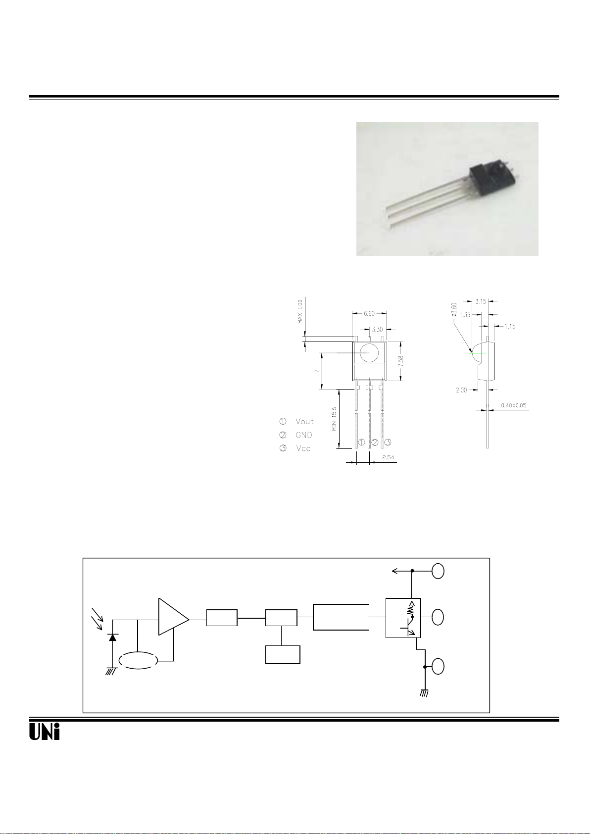
Unit : mm
BLOCK DIAGRAM
1/12/01
Uni ty Opto Technolo gy C o., Ltd.
The MIM-0KM1AKL is miniaturized infrared receivers for
remote control and other appplications requiring improved
ambient light rejection.
The separate PIN diode and preamplifier IC are assembled
on a single leadframe.
The epoxy package contains a special IR filter.
This module has excellent performance even in disturbed
ambient light applications and provides protection against
uncontrolled output pulses.
Output
V
S
GND
ABLC
TRAP BPF
TRIMMING
f
o
MIM-0KM1AKL
Absolute Maximum Ratings
Item Symbol Ratings Unit Remark
Supply voltage V
CC
3.0 ~ 5.8 V
Operating temperature T
opr
-10 ~ + 60 ℃
Storage temperature T
stg
-20 ~ + 75 ℃
Soldering temperature T
sd
260 ℃ Maximum 5 seconds
Electro-optical characteristics (Vcc=2.4V)
Parameter Symbol Min. Typ. Max. Unit Remarks
Current consumption Icc 5.0 mA Under no signal
Response wavelength λp 940 nm
Tuning frequency
f
0
37.9
KH
Z
Output form
- - - - - active low output - - - - -
H level output voltage V0h 2.2 V
L level output voltage V
0
l 0.5 V
H level output pulse width Twh 400 800 μs
L level output pulse width Twl 400 800 μs
Distance between emitter & detector L
1(Vcc=3V)
10.0 m Note 1
L
2(Vcc=2.4V)
7.0 m
Half angle △Θ ±45 deg Horizonal direction
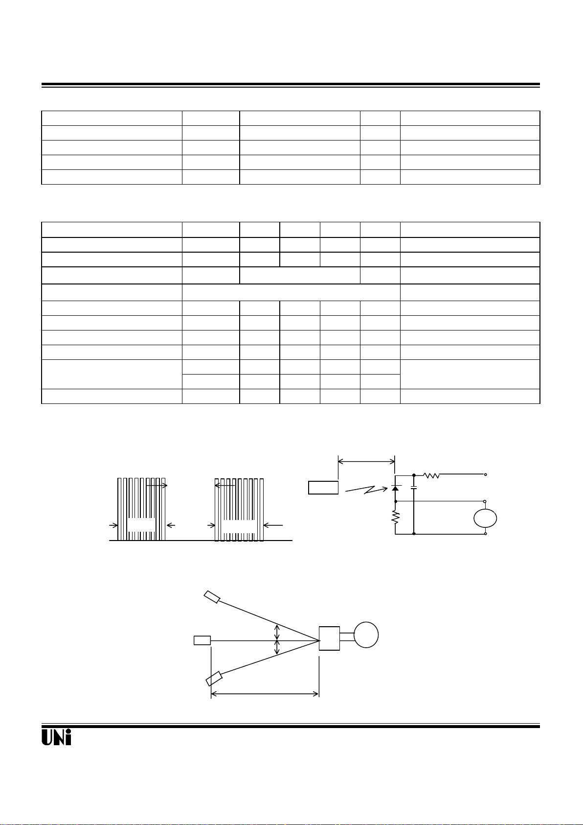
Test Method
A. Standard Transmitter
B. Detection Length Test
1/12/01
Uni ty O pto Te chnology Co., Ltd.
@
Ta=25℃
(Ta=25°C , Vcc=2.4V)
ON/OFF pulse width satisfied from 25 cm to detection limit
600µs
600µs
600µs
Fig 1. Burst Wave Fig 2. Standard Transmitter Measurement circuit
+2.4V
10µF
PD351610
k
V
Transmitter
Duty 50%
Oscilloscope
GND
10kΩ
θ
θ
V
out
D.U.T
L
Transmitter output
θ: indicates horizontal and vertical directions

MIM-0KM1AKL
C. Pulse Width Test
Application Circuit
CHARACTERISTIC CURVES (T
A
=25℃℃℃℃)
NOTE 1. Distance between emitter & detector specifies maximum distance that output wave form satisfies
the standard under the conditions below against the standerd transmitter.
(1)Measuring place ………Indoor without extreme reflection of light.
(2)Ambient light source… Detecting surface illumination shall be 200±50Lux under ordinary
hite fluorescense lamp of no high frequency lighting.
(3)Standard transmitter … Burst wave indicated in Fig 1. of standard transmitter
shall be arranged to 50mVp-p under the measuring circuit specified in Fig 2.
1/12/01
Unity Opto T ech nol ogy C o., Ltd.
SUPPLY VOLTAGE vs. SUPPLY CURRENT
Supply Current Icc (mA)
2.2
2.8
2.7
2.6
2.4
2.0
2 3 4 5
6
7 8
Supply Voltage Vcc (V)
INPUT LEVEL vs.OUTPUT PULSE WIDTH
Input Level VIN (mV
P-P
)
400
500
600
700
800
900
0.1
1 10 100
1000
Burst length * 600µs, cycle = 1.2ms
tpw: Average value of output from start
of signal input to 60th pulse
Output Pulse Width t
PW
(
µ
s)
Input Level (mV
p-p
)
600µs
Transmitter output
DUT output pulse
600µs
V0l
V0h
Twl
Twh
MIE-544A2
MIM-0KM1xKL
3
1
2
102P
Decoder
GND
Vcc **)
*) only necessary to supress power supply disturbances.
**) tolerated supply voltage range : 2.4V < Vcc < 5.8V
C

MIM-0KM1AKL
Reliability
Test item Test condition Standard
High temparature Ta=+60℃ Vcc=5.0 V t=240H Note 2.
High temp. & high humi. Ta=+40℃ 90%RH Vcc=5.0V t=240H Note 2.
Low temparature Ta= -10℃ Vcc=5.0V t=240H Note 2.
Heat cycle -20℃(0.5H) ~ +75℃(0.5H) 20cycle Note 2.
Dropping Test devices shall be dropped 3 times naturally Note 3.
onto hard wooden board from a 75cm height position.
NOTE 2. (electro-optical charactistics) shall be satisfied sfter leaving 2 hours in the normal temperature .
NOTE 3. (electro-optical charactistics) shall be satisfied and no conoid deforms
and destructions of appearance .(excepting deforms of terminals)
Inspection standard
1.Among electrical characteristics , total number shall be inspected on items blow.
1-1 front distance between emitter & detector
1-2 Current consumption
1-3 H level output voltage
1-4 L level output voltage
2.Items except above mentioned are not inspected particularly , but shall fully satisfy
CAUTION ( When use and storage of this device )
1.Store and use where there is no force causing transformation or change in quality .
2.Store and use where there is no corrosive gas or sea(salt) breeze .
3.Store and use where there is no extreme humidity .
4.Solder the lead-pin within the condition of ratings. After soldering do not add extra force .
5.Do not wash this device . Wipe the stains of diode side with a soft cloth. You can
use the solvent , ethylalcohol or methylalcohol or isupropylene only .
6.To prevent static electricity damage to the Pre-AMP make sure that the human body
, the soldering iron is connected to ground before using .
7.Put decoupling device between Vcc and GND for reduse the noise from power supply line .
8.The performance of remote-control system depends on environments condition and ability
of periferal parts. Customer should evaluate the performance as total system in those conditions
after system up with components such as commander , micon and this receiver module .
Guarantee period and scope
1.Guarantee period
One year after delivery to desired place .
2.Guarantee scope
A re-delivery of goods will be carried out if the cause of malfunction lies in our
device .However no responsibilities be taken for the inconveniences caused by
the malfunction of our devices .
Others
1.This device is not design to endure radiative rays and heavily charged particles .
2.In case where any trouble or questions arise,both parties agress to make full discussion
covering the said problem .
1/12/01
Uni t y Opt o Technology Co. , Ltd.
 Loading...