

Page 1
P/N:110401109668X
UT-CS09A/D
Flex Clamp Current Sensor
Thank you for purchasing this brand new UNI-T product. In order to safely and correctly use this
device, please read this manual carefully, especially the Safety Instructions section.
Please keep the manual accessible near the device for future reference.
1. Introduction
2. Open Box Inspection
3. Safety Instructions
4. Symbols
5. Structure
6. Operation Instructions
7. Technical Specifications
A. General specifications
B. Operating environment
C. Electric specifications
8.Maintenance
A. General maintenance
B. Battery installation & replacement
1. Instruction
UT-CS09A/UT-CS09D is a stable, safe and reliable 3000A AC Rogowski flex Clamp Current Sensor
(hereinafter called current sensor). The core of the design is the Rogowski coil.
Warning:
To avoid electric shock or injury, please read Safety Instructions and Warnings before operating this
product.
2. Open Box Inspection
Open the package box and take out the device. Please check whether the following items are deficient
or damaged and contact your supplier immediately if they are.
User manual ----------------------- 1
BNC adapter------------------------ 1 pc
Battery: 1.5V AAA----------------- 3 pc
pc
4. Symbols
Double insulation
Grounding
Warning
AC (Alternating Current)
Battery
High voltage hazard
Comply with European Union standards
Conforms to UL STD. 61010-1, 61010-2-032, 61010-031,
Certified to CSA STD. C22.2 No. 61010-1, 61010-2-032, 61010-031.
It is applicable to test and measuring circuits connected at the source of the building’s
CAT IV
low-voltage MAINS installation.
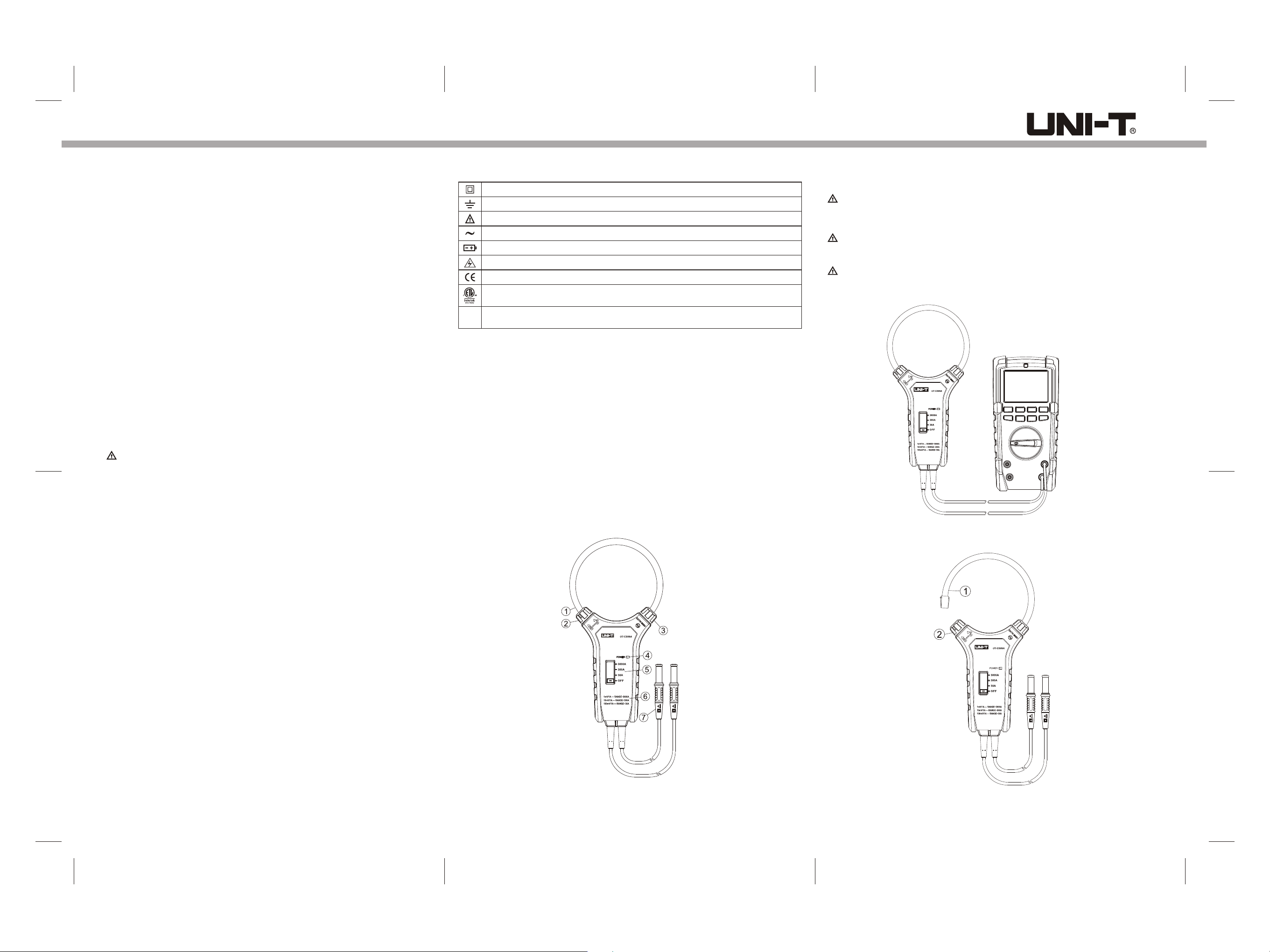
5.Structure
1. Flexible Rogowski coil
2. Flexible clamp lock
Rotate the knob according to the arrow mark on the case to lock or unlock
3. Fixed piece
4. Power indicator
Normal status: constant red light
Low power (<3.3V): flash once for every 1s period. Please replace the batteries.
5. Switch
A. 30A
For measuring 1.5A~30A
B. 300A
For measuring 30A~300A
C. 3000A
For measuring 300A~3000A
D. OFF
Switch off the sensor
6. Corresponding output voltage
A. 30A range: 1A -> 100mV
B. 300A range: 1A -> 10mV
C. 3000A range: 1A -> 1mV
7. Voltage signal output terminal
The corresponding voltage output of AC current measured through flexible current sensor.
6.Operations
BNC terminal can be used to connect flexible current sensor to read out on oscilloscope
Warnings:
To avoid false reading, do not use low input impedance settings when using oscilloscopes as readouts.
AC measurement
Warning:
Before measuring, switch off the conductor to be measured. Do not turn on the conductor before the sensor
is locked around the conductor to be measured.
Caution:
Keep your hands away from the Rogowski ring and conductor to be measured.
1.Connect the sensor with alternating voltage measure device e.g. multimeter. (see figure 2)
Flex Clamp
Current Sensor
Figure 2
2. Unlock the Rogowski coil according to (see figure 3).Section 5.2
3. Safety Instructions
In this manual, a Warning identifies conditions and actions that pose hazard(s) to the user or the
test device.
This device strictly follows CE standards: IEC61010-1; IEC61010-031; IEC61010-2-032 as well as
CAT IV 600V, RoHS, pollution grade II, and double insulation standards.
If the clamp is used in a manner that is not specified in this manual, the protection provided by the
device might be impaired.
1) Do not use the device if the rear cover or the battery cover is not covered up.
2) When measuring, keep fingers behind the finger guard on the measuring head. Do not touch
bare cables, connectors, unoccupied input terminals or circuit being measured.
3) Before measuring, the switch should be on correct position. Do not switch positions during
measurement.
4) Do not use the clamp on any conductor with voltages higher than DC 1000V or AC 750V.
5) Use caution when working with voltages above 33V AC rms. Such voltages pose shock hazard.
6) Do not use the device to measure current higher than specified range. If current value being
measured is unknown, select 3000A position and reduce accordingly.
7) To avoid false reading, replace the battery if “POWER” indicator flashes. Remove the battery
if the sensor is left unused for a long time.
8) Do not change the internal circuit of the device.
9) Do not store or use the sensor in high temperature, high humidity, explosive, or strong magnetic
field environments.
10) Use soft cloth to clean the case, do not use abradants or solvents.
11) Do not use when the jaw or "jaw end" is worn.
Flex Clamp
Current Sensor
Figure 1
Flex Clamp
Current Sensor
Figure 3
Page 2
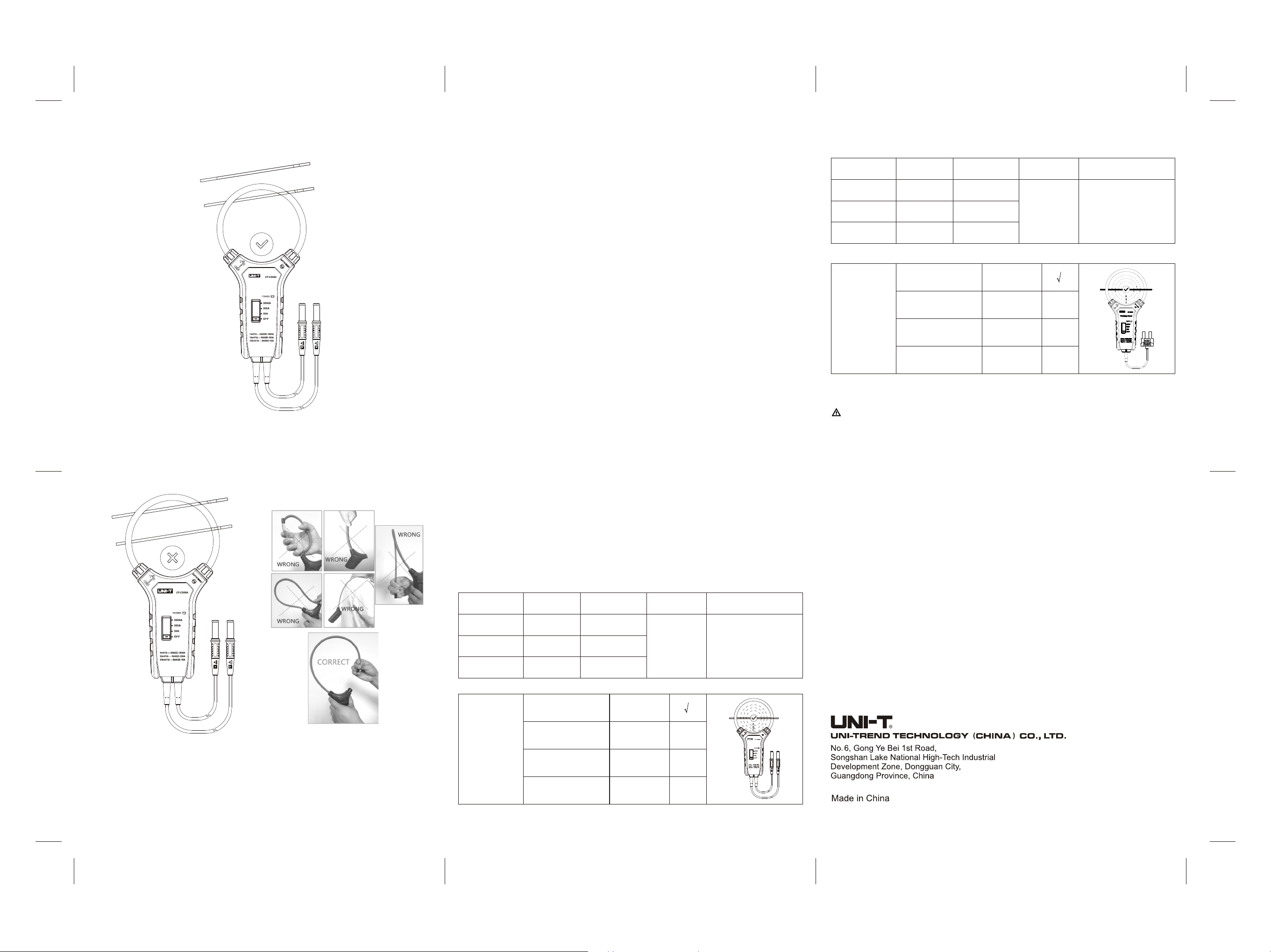
3. Use the Rogowski coil to wrap and lock around the conductor to be measured. (see figure 4)
Flex Clamp
Current Sensor
Figure 4
4. Turn on the sensor, then power on the conductor.
5. Read the value displayed on the multimeter. (Max Value=3.0V). If the current to be measured is
over the range, please select appropriate range (30A/300A/3000A)
6. Improper operation example (see figure 5a, 5b).
7. Technical specifications
A. General specifications
Max output voltage:---------------------------- 3.00V (AC)
Over range indication:------------------------ reading> 3.00V (AC)
Low power indication:------------------------ “POWER” indicator flashes, battery voltage<3.3V,
please replace the battery
Sensor type:------------------------------------- Rogowski clamp sensor
Position error: ---------------------------------- At central position: ±3.0% of reading
outside central area: additional error according to zone
ABC. (see Electric specification)
Drop test: ---------------------------------------- 1 meter
Measuring head size:------------------------- UT-CS09A Length=25.4cm (10")
UT-CS09D Length= 45.7cm (18")
Conductor trace line:--------------------------- Max diameter: 14cm
Electromagnetic field interference:--------- unstable performance or incorrect reading
Battery:-------------------------------------------- AAA 1.5V (3pcs)
B. Operating environment
Max altitude:------------------------------------- 2000m
Safety standard:-------------------------------- IEC61010-1; IEC61010-031
IEC61010-2-032; CAT IV 600V
Pollution grade:---------------------------------- 2
Information of usage:--------------------------- Indoor
Operating temperature:------------------------ 0˚C~50˚C
Operating humidity:-----------------------------≤80%RH
Storage:------------------------------------------- -20 ˚C ~ 60 ˚C (≤80%RH)
C. Electric specifications
Accuracy:----------------------------------------- ±(%of reading+ numerical number of least significant
digit) 1 Year Warranty
Environment temperature:-------------------- 23 ˚C ± 5 ˚C
Environment humidity:------------------------- ≤80%RH
Temperature coefficient:---------------------- 0.2×(specified accuracy)/ ˚C (<18 ˚C or >28 ˚C)
(2) UT-CS09D AC current measurement:
Range
30A
300A
3000A
Additional
accuracy range
when measuring
outside of
optimum location
(Assume no
external electric
or magnetic field)
Resolution
0.1A
1A
10A
Corresponding
voltage
~100mV/1A
~10mV/1A
~1mV/1A
Central optimum
measurement location
35mm(1.4”)
away from center
50mm(2.0”)
away from center
60mm(2.4”)
away from center
±(3%+5)
Additional 1.0%
additional 1.5%
additional 2.0%
Accuracy (at
central position)
±(3%+5)
Zone A
Zone B
Zone C
Frequency Response
45Hz~500Hz
8. Maintenance
A. General maintenance
Warning: remove the test probes before open the rear cover or it may pose a shock hazard.
a. The maintenance and service must be implemented by qualified professionals or designated
departments.
b. Clean the case with a dry cloth. Do not use abradants or solvents
B. Battery installation & replacement
The sensor uses three AAA 1.5V alkaline batteries for operation.
To install or replace the battery:
a. Switch off the sensor and remove the test probes from the terminal input.
b. Unscrew the battery cover, remove the cover and install new batteries ensuring that the correct polarity
is observed.
c. Use batteries of the same type
d. Replace the battery cover and screw up.
Flex Clamp
Current Sensor
Figure 5a Figure 5b
Shut down
After measurement, switch to OFF position to shut down the device.
Buzzer
The buzzer will go off at effective range.
(1) UT-CS09A AC current measurement:
Range
30A
300A
3000A
Additional
accuracy range
when measuring
outside of
optimum
location
(Assume no
external
electric or
magnetic field)
Resolution
0.1A
1A
10A
Central optimum
measurement location
15mm(0.6”)
away from center
25mm(1.0”)
away from center
35mm(1.4”)
away from center
Corresponding
voltage
~100mV/1A
~10mV/1A
~1mV/1A
±(3%+5)
Additional2.0%
additional 2.5%
additional 3.0%
Accuracy (at
central position)
±(3%+5)
Zone A
Zone B
Zone C
Frequency Response
45Hz~500Hz
Flex Clamp
Current Sensor
 Loading...