

Page 1
Please read the manual and “Safety Information”
and Warnings carefully before using the meter.
Warning
UT204A is a 4000-count AC/DC digital clamp meter
with stable performance, high degree of safety and
reliability. It is designed with large-scale integrated
circuits and dual integral A/D converter as its core,
overload protection for all ranges and novel structure,
which make it a superb tool for electricians. The
meter can measure AC/DC voltage, AC/DC current,
resistance, diode, continuity, capacitance, frequency
and temperature, etc.
I.Overview
II. Unpacking Inspection
III. Safety Information
Please open the package box and take instrument
out. Please check if following items are deficient or
damaged or not.
1 pc
1 pair
1 pc
1.
2. Test Probes
3. Temperature probe
4. Guarantee certificate 1 pc
Please contact your supplier instantly if any
item is deficient or damaged.
The instrument is designed and manufactured in
compliance with GB4793, IEC61010-1 and IEC
1010-2-032: Double Insulation, Overvoltage CAT
Ⅱ600V & CATⅢ 300V and Pollution Degree 2.
A Warning identifies conditions and actions that
may pose hazards to the user, or cause damage
to the Meter or equipment under test. Please pay
attention to warnings and use the meter as
specified as follows, otherwise the protection offered
by the clamp meter would be impaired.
1. Please inspect clamp meter and test leads before
use to avoid damage or abnormal use. Please
do not use the clamp meter again if test leads or
shell insulation is damaged obviously with LCD
display failure or clamp meter cannot operate
normally.
2. It is strictly prohibited to use clamp meter before
covering rear cover and battery cell to avoid
electric shock.
3
. Fingers cannot exceed the finger guard of probe
during measurement. Do not touch nude electric
wires, connector, unused input end or circuits
during measurement to avoid electric shock.
4. Function switch must be in correct position
before measurement. It is strictly prohibited to
change ranges during measurement to avoid
damage of clamp meter.
5. Do not exert more than 600V between terminal
of clamp meter and grounding to avoid electric
Shock or damage of clamp meter.
6. To operate the instrument carefully under DC 60V
or AC 30V to avoid electric shock.
7. Do not measure voltage or current which is more
than permissible input value. Be sure to place
function range switch to the maximum range
position if scope of measured value cannot be
determined. Be sure to cut off circuit power and
discharge all capacitors before measuring
of online resistance, diode or circuit. Disconnect
probe and measured circuit then remove probe
from input end of clamp meter and cut off power
after measurement.
8. Replace the battery when“ ” shows on the
LCD to ensure the measuring accuracy.To
take battery out if clamp meter has not been
used for a long time.
9. Please do not alter internal wiring of clamp meter
randomly to avoid instrument damage and safety
danger.
10.Do not store or use clamp meter in environment
of high-temperature, high-humidity, flammables,
explosives and strong current magnetic Field.
11.Please clean the instrument shell by soft cloth
and neutral detergent during maintenance. Do
not use abrasive or solvent to avoid shell
corrosion which may cause any damage to the
clamp meter or personal injury.
IV.Electrical Symbols
Double Insulated
AC
Diode
Warning prompt
AC or DC
To meet European Union standard.
Grounding
DC
Low battery Indication
Buzzing ON/OFF
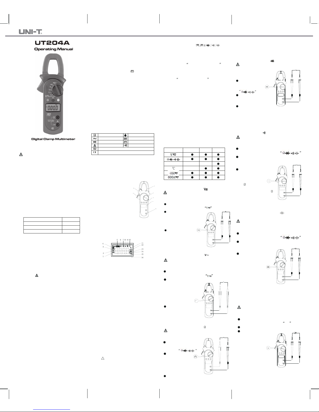
V.The Meter Structure (See Figure 1)
1. Input end;
2. LCD digit display;
3. Function key: To select basic functions;
4. Measurement function knob: White mark is
initially set value; Blue mark is validated after
selecting blue key;
5. Clamp head trigger: To press
the trigger to loosen clamp
head.
Clamp head will be
again
trigger;
6. Hand protection: It prevents
users from touching any
dangerous area.
7. Clamp head: It is a device to
convert current to voltage. Single
conductor of measured current must pass through
center of clamp head perpendicularly;
1
2
5
7
6
4
3
Figure 1
tightened
if loosening the
measure AC/DC current to
VI.Display Symbols(See Figure 2)
3
4
6
10
11
13
12
5
8 9
15
1
2
16
7
14
Figure 2
1. Indicator for AC Measurement;
2. Indicates negative polarity;
3. Indicator for DC Measurement;
4. Low Battery Indication;
5. under Auto-Ranging Mode;
6. Indicator for Diode Test;
7. Indicator for Continuity Test;
8. Indicator for Duty Cycle Test;
9. Data Hold is Active;
10. Indicator for Relative Measurement;
11. Temperature Unit (℃);
12. Resistance Unit (Ω, KΩ and MΩ);
13. Frequency Unit (Hz);
14. Capacitance Unit (nF and µF);
15. Current Unit (A);
16. Voltage Unit (mV and V)
VII. Key Functions and Automatic
Shutdown
1.HOLD
It is to maintain displayed reading by triggering.
Displayed value will be locked for constant display
by pressing the key once. It can be pressed again
to release locking status and return to common
measurement status.
2.REL
3.SELECT
To switch over between
Note: Automatic shutdown function will be
cancelled if pressing SELECT key to wake up
the meter from the sleep mode.
4.Automatic Shutdown
Clamp meter will power off automatically
(under sleeping status) to save electric energy if
function key and knob switch fail to operate
within 15 minutes during measurement.
Clamp
meter will start up automatically (under
working status) by rotating function key under
automatic shutdown status. (Please refer to Item
6 for effective key operation.)
Press down the key to use current reading as the
reference value and reset the display to "0". This
reference value is subtracted every time from
measuring results until you press the key again
to exit the mode.
Note: Automatic shutdown function will be
cancelled by pressing SELECT key for wake-up
under sleeping status.
5.Buzzer
Buzzer will beep if pressing any effective function
key under any measurement range. It will not ring
if the key is invalid. Buzzer will issue 5 warning
voices continuously about 1 minute before
automatic shutdown. It also will issue a long-term
voice before power off.
6.Key validity
Not all keys are valid under any range. As indicated
below, corresponding functions or to wake up the
meter can be achieved only when the keys are valid.
Key
Hz
SELECT
N/A N/A
N/A
REL HOLD
VIII. Measurement Instructions
1. DC voltage measurement ( ) (See Figure 3)
Warning: Clamp meter cannot be used for
conductive object of which voltage exceeds
AC/DC 600V.
To set knob.
Please place function knob to
To select key functions.
The clamp meter defaults at
DC Voltage and auto-ranging
mode. Press REL △ to
access relative mode.
To connect load.
V
T o disconnect probe
and measured circuit then
remove probe from input
end after all measurement
operations.
Figure 3
2. AC voltage measurement ( ) (See Figure 4)
Warning: Clamp meter cannot be used for
conductive article of which voltage exceeds
AC/DC 600V
.
To set knob.
Please place function knob to
To select key functions.
Press SELECT button to
select AC voltage mode,
it defaults at auto
-ranging.Press
REL△ to access
relative mode.
To connect load.
V
~
~
Figure 4
To disconnect probe and
measured circuit then
remove probe from
input end after all measurement operations.
3. Resistance measurement ( ) (See
Figure 5)
Warning: Be sure to cut off circuit power and
discharge residual charge of all capacitors
before load connection.
To set knob.
Please place function
knob to
To select key
functions.
It defaults at Ω
mode and in auto
-ranging.Press REL
△ to access relative mode.
To connect load.
Figure 5
To gain excellent measured result by separating
element from circuit.
To disconnect probe and measured circuit then
remove probe from input end after all
measurement operations.
4. Diode measurement ( ) (See Figure 6)
Warning: Be sure to cut off circuit power and
discharge residual charge
of all capacitors before
load connection.
To set knob.
Please place
function knob to
To select functions.
To select diode detection
by pressing SELECT key;
To connect load.
.
Figure 6
To gain excellent measured result by separating
element from circuit.
To disconnect probe and measured circuit then
remove probe from input end after all
measurement operations.
5. Continuity Test ( )
(See Figure 7)
Warning: Be sure to cut off circuit power and
discharge residual charge of all capacitors
before load connection.
To set knob.
Please place function knob to
To select functions.
To select conductance detection by pressing
SELECT key;
To connect load.
.
Figure 7
Buzzer will ring if
measured resistance
is less than
10
. It can ring or
not ring if measured
resistance exceeds 10
.
To disconnect probe and
measured circuit then
remove probe from input
end after all measurement operations.
6. Capacitance measurement ( ) (See
Figure 8)
Warning: Be sure to cut off circuit power and
discharge residual charge of all capacitors
before load connection.
To set knob.
Please place function knob to
To select functions.
To select capacitance detection by pressing
SELECT key;
To connect load.
Figure 8
Measurement notice:
1)Be sure to reset by
pressing REL key
before measurement.
2)Instrument reading will
delay for about 30
seconds normally when
measuring large capacitance.
To disconnect probe and measured circuit then
remove probe from input end after all
measurement operations.
7.Frequency measurement (Hz) (See Figure 9)
Warning: Clamp meter cannot be used for
conductive objecte of which voltage exceeds
AC/DC 600V.
To set knob.
Please place function knob to Hz
To select key functions.
To connect load.
Hz
Figure 9
To disconnect probe and
measured circuit then
remove probe from
input end after all
measurement
operations.
Operating Manual
Page 2
P/N:110401104251X
8.Temperature measurement ( ) (See
Figure 10)
To set knob.
To place function knob to
Figure 10
To select functions.
To connect load.
1) LCD will display OL if failing to insert
temperature sensor. Clamp meter will display
current indoor temperature after user inserting
temperature sensor.
2) The protection for the temperature range is
1KΩ resistor(R59). any conductor with voltage
present cannot be inserted into input jack to
avoid.
A
9. DC current measurement ( ) (See
Figure 11)
To set knob.
To place function knob to 40A or 600A
To select functions.
The meter defaults at DC Current Mode.
To connect load.
Figure 11
Please do not loosen trigger suddenly. As a
sensitive device, Hall element will be sensitive to
heat and mechanical stress to different extents
in addition to magnetic sensitivity. Collision will
cause short-term reading variation. Please open
the clamp head by pressing trigger then fetch
measured conductor by clamp head and loosen
trigger slowly until it is closed completely. Please
check if measured conductor is in the middle of
clamp head or not. Additional error may be caused
if failing to place it in the middle of clamp head.
Clamp meter can measure a current conductor
once and measurement reading error may be
caused if measuring two or more current
conductors at the same time.
10. AC current measurement ( ) (See
Figure 12)
To set knob.
To place function knob to 40A
or 600A
To select functions.
To press SELECT key for AC current
measurement;
To connect load.
Figure 12
Please do not loosen trigger suddenly. As a
sensitive device, Hall element will be sensitive to
heat and mechanical stress to different extents
except magnetic sensitivity. Collision will cause
short-term reading variation.Please open the
clamp head by pressing trigger then fetch meas
-ured conductor by clamp head and loosen trigger
slowly until it is closed completely. Please check
if measured conductor is in the middle of clamp
head or not. Additional error may be caused if
failing to place it in the
middle of clamp head.
Clamp meter can measure
a current conductor
IX. Technical Indicators
1.General specification
LCD display: 4000 counts;
Polarity display: Automatic display;
Overload display: To display OL or -OL ,
Low Battery Indication: shows as battery
voltage is less than required working voltage.
Sampling rate: 3 times/second;
Sensor category: Hall affect sensor for DC/AC
measurement;
Error of testing position: 1.0% of additional
reading error may be caused if failing to place
measured source to center of clamp head during
current measurement;
Shock-resistant: pass 1m drop test;
Max.clamp Opening : 28mm diameter;
Max. Tested Conductor: 26mm diameter;
Influence of electromagnetic field: Device used
near electromagnetic field may display unstable
or incorrect reading;
2.Environment limitation
Indoor use
The
altitude height: 2,000m
Safety rules: ICE 1010-1 CAT.II 600V
CAT.III300V
Pollution degree: 2
Operation temperature & humidity: 0 to 30
(not more than 80%R.H.)
30 to 40 (not more than 75%R.H.)
40 to 50 (not more than 45%R.H.)
Storage temperature & humidity: -20 to +60
(not more than 80%R.H.)
3.Electrical specification
Accuracy:
Calibration period for 1 year
Ambient temperature: 23 5
Ambient humidity: Not more than 80% R.H.
Temperature coefficient: 0.1*precision/1
(1)DC voltage ( )
Range
400.0mV
4.000V
40.00V
400.0V
600V
Resolution
0.1mV
1mV
10mV
100mV
1V
Accuracy
(0.8%+3)
(0.8%+1)
(1%+3)
Overload protection
600V DC/AC
Input impedance: 10M Ω
(2)AC voltage ( )
Range
Resolution
Accuracy
Overload protection
4.000V
40.00V
400.0V
600V
1mV
10mV
100mV
1V
(1%+5)
(1.2%+5)
600V DC/AC
Input impedance: 10M //not less than 100pF
Frequency response: 40Hz~400Hz
AC conversion type:
AVG response, RMS value for sinewave input.
(3) Resistance ( )
Range
400.0
4.000K
40.00K
400.0K
4.000M
40.00M
Resolution
100m
1
10
100
1K
10K
Accuracy
(1.2%+2)
(1%+2)
(1.2%+2)
(1.5%+2)
Overload protection
600Vp
(4) Diode test ( )
Range
Resolution
Accuracy
Overload protection
1mV
To display
positive pressure
drop. (Open circuit
voltage is about
600Vp
(5) Continuity test ( )
Range
Resolution
Accuracy
Overload protection
600Vp
Buzzer will ring if
equal to
10 .
(Open circuit
voltage is about
0.1
Note: Buzzer will ring or not ring if measured
resistance exceeds 10
approximate
1.48V.)
it is less than or
0.45V.)
(6) Capacitance ( )
Range
Resolution
Accuracy
Overload protection
600Vp
4nF
40nF
400nF
4µF
40µF
µ
F
0.001nF
0.01nF
0.1nF
0.001µF
0.01µF
0.1µF
(4.0%+3)
(5.0%+10)
To measure under RELATIVE measurement mode;
(7) Frequency (Hz)
Range
10Hz
100Hz
1kHz
10kHz
100kHz
1MHz
10MHz
Resolution
0.001Hz
0.01Hz
0.1Hz
1Hz
10Hz
100Hz
1kHz
(Reading is only for reference.)
Accuracy
Overload protection
(0.5%+3)
600Vp
Sensitivity: 300mV rms if 100kHz;
600mV rms if 100kHz;
800mV rms if 1MHz;
(8) Temperature ( )
Range
-40 ~
1,000
Accuracy
Overload protection
-40 ~0
0 ~400
400 ~1,000
(8%+5)
(2.5%+3)
(3.0%+3)
Plug-in resistance
of 1K
Note:
1) There is no voltage protection for temperature
ranges. It is not allowed to insert electrified
conductor into jack to avoid burnout of 1K
resistance;
100
2) K type thermocouple (Ni-Cr~Ni-Si) is only
suitable to temperature measurement of less
than 230 . Rod type temperature sensor shall
be used for temperature measurement of more
than 230
.
(9) DC current ( )
Range
40.00A
600A
0.01A
1A
Accuracy
(2%+5)
Overload protection
600A DC/AC
Note:
Current measurement function must be operated
between
0 and 40 . Current direction is
from bottom to top for positive reading during
DC current measurement. (As shown in Figure
11, panel is on the top and bottom cover is on the
bottom.) Please do not loosen the trigger
suddenly after pressing. As a sensitive device,
Hall element will be sensitive to heat and
mechanical stress to different extents addition to
magnetic sensitivity. Collision will cause short
-term reading variation.
More correct
by following operation methods:
Press the trigger and open clamp head to
fetch measured conductor by clamp head then
loosen trigger slowly until clamp head is closed
completely. Please check if measured conductor
is in the middle of clamp head or not. Additional
reading error of 1.0% may be caused if failing
to place it in the middle of clamp head;
To remove clamp head away from the current
conductor;
To press REL key for display resetting;
To repeat step
;
To gain more correct reading by above
measurement steps;
Resolution
measurement can be guaranteed
(10) AC current ( )
Range
40.00A
600A
0.01A
1A
Accuracy
Overload
protection
600A DC/AC
Resolution
(2.5%+8)
(2.5%+5)
Frequency
response
50Hz~60Hz
Note:
Current measurement function must be fulfilled
between 0 and 40 . Frequency response:
50Hz~60Hz;
Instable or incorrect inductive reading with less
than 10 words may be displayed in AC current
gear and it will not influence measurement result.
Please do not loosen trigger suddenly. As a
sensitive device, Hall element will be sensitive to
heat and mechanical stress to different extents
in addition to magnetic sensitivity. Collision will
cause short-term reading variation.
AC conversion type:
AVG response; RMS value for sinewave input.
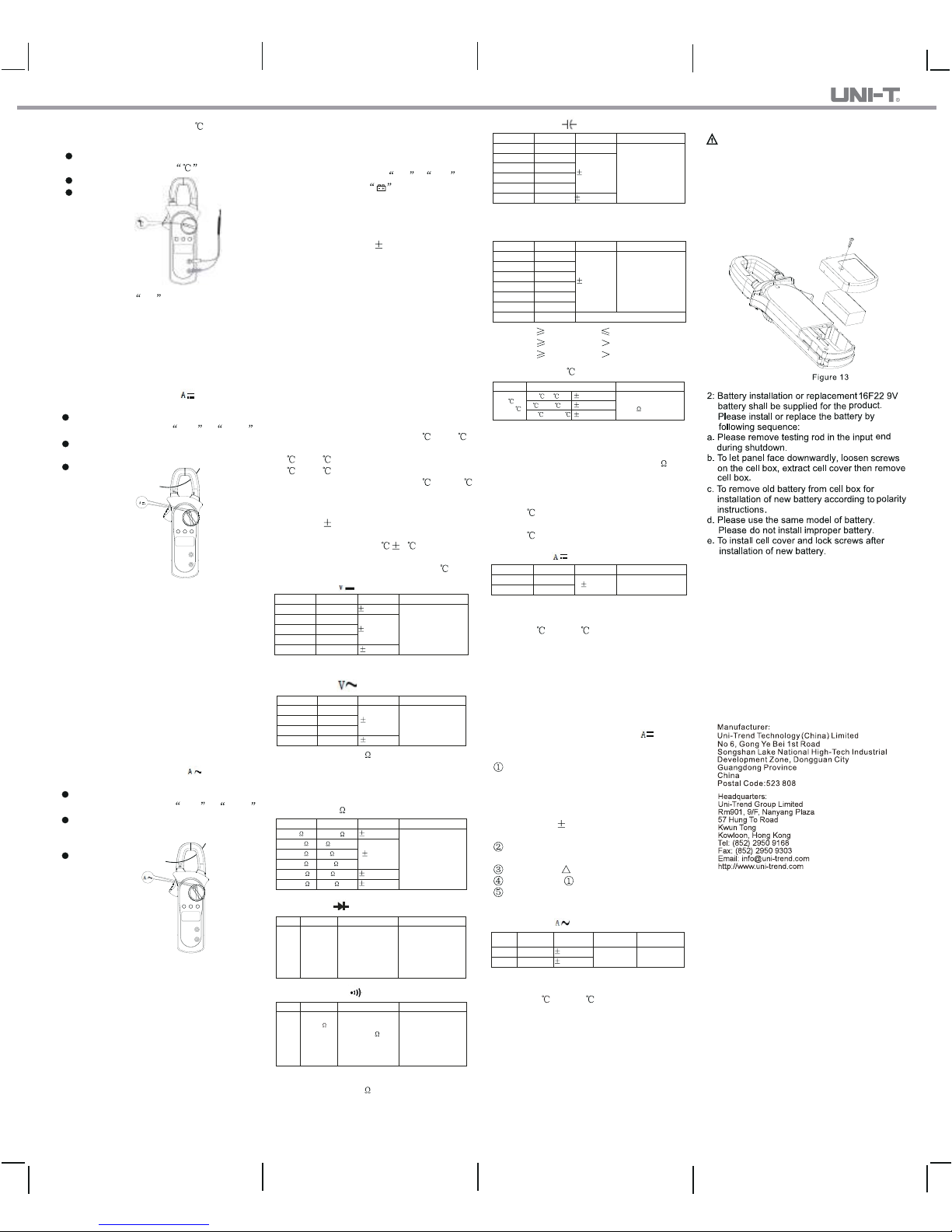
X. Maintenance(See Figure 13)
Warning: Please remove testing rod before
opening bottom cover to avoid electric shock.
1. General maintenance
A. The clamp meter must be repaired and served
by qualified professional repair personnel or
designated repair department.
B. To clean the shell periodically by dry cloth.
However, it is not allowed to use detergent
with abrasive or solvent .
once and measurement reading error may be
caused if measuring two or more current cond
-uctors at the same time.
(a% readings + b digits)
 Loading...