

Page 1
Overview
This Operating Manual covers inf ormation o n
safety and cauti ons. Please read t he relevant
in form atio n care ful ly and ob ser ve all th e
Warnings and Notes strictly.
Warning
To avoid electric shock or pers onal injury, read
the “Safety Infor mation” carefully before using
the Meter.
Mode l UT202 A is 20 00-coun t stabl e, safe and
reli able di gital c lamp mu ltimete r(herea fter
refe rred to as "th e Meter "). It is desi gned wi th
larg e-scale integr ated ci rcuits and A/D
conv erter a s the c ore as well as the ov erload
prot ection and nov el stru cture, which m ake
it a superb tool f or elec trician s.
The Meter can measure AC/DC Voltage, AC
Current, Resistance, Diodes, and Continuity.
Unpacking Inspection
Open the package case and take out the Meter.
Check t he following items carefully for any
missing or damaged part:
Item Description Qty
1 English Operating Manual 1 piece
2 Test Lead 1 pair
In t he event you find any missi ng or d amaged
part please contact your dealer immediately.
Safety Information
Th is Me ter c omp lie s wit h the s tan dar d
IEC610 10: Poll ution De gree 2, Overvol tage
Category (CATII 600V, CAT III 300V) and Double
Insulation.
CATI I: Loca l l evel , a ppli ance , P ORTABL E
EQ UIP MENT e tc., w ith s mall er tr ans ient
overvoltages than CATIII.
CAT III: Distribution level, fixed installation, with
smaller transient overvoltages than CAT IV
Use the Meter only as specified in this operating
manual, otherwise the protection provided by
the Meter may be impaired.
In thi s manual, a Warning identifi es conditions
and actions th at pose hazards t o the user, or
may damage the Meter or the equipment under
test.
A Note ide ntifi es t he infor matio n t hat user
should pay attention to.
Warning
To av oid po ssible electric shoc k or persona l
inju ry, and to avoid poss ible damage to the
Meter or to the equipment under test, adhere to
the following rules:
.esac eht tcepsni reteM eht gnisu erofeB ●
Do not us e the Meter if it is d amaged or the
case (or part of the case) is removed. Look for
cracks or missing plastic. Pay a ttention to the
insulation around the connectors.
● In spec t the t est l ead s for da mag ed
insula tion o r expos ed meta l. Check the tes t
lead s for cont inuity. Rep lace damaged test
leads with identical model number or electrical
specifications before using the Meter.
● Do not apply more than the rated voltage,
as marked on the Meter, between the terminals
or be tween any terminal and grounding. If the
valu e t o be mea sured is unkno wn, use the
● When measurement has been completed,
disc onnect the connec tion between the test
leads and the circuit under test, remov e the
testing leads away from the input ter minals of
the Meter and turn the Meter power off.
● Th e ro tary swit ch should be pla ced in
the right positi on an d no any changeov er of
range shall be made w hen mea surement is
conducted to prevent damage of the Meter.
● Do not carry out the measuremen t when
the Meter’s back case and battery compartment
are not closed to avoid electric shock.
● Do not input higher than 600V between the
Meter ’s termina ls and the gr ounding t o avoid
electric shock and damages to the Meter.
● When the Meter is workin g at an e ffective
vol tage over 60V in DC or 30V rms in AC,
special care should be taken for there is danger
of electric shock.
● Use the proper termina ls, f unction, and
range for your measurements.
● Do not u se or sto re the M eter in a n
env ironme nt o f hi gh t empera ture, humi dity,
explo sives, i nflammab les a nd str ong m agnetic
fie ld. T he perf orma nce of the Me ter may
deteriorate after dampened.
● Wh en using the te st l eads, ke ep y our
fingers behind the finger guards.
● Discon nect circuit power and dischar ge
al l h igh- volt age ca paci tors b efor e t esti ng
resistance, continuity and diode.
● Replace the battery as soon as the battery
indicator appears. With a low battery, the
Meter might produce false readin gs that can
lead to electric shock and personal injury.
● When servic ing th e Mete r, use only use
the r eplaceme nt parts with the same mo del
or id entical electrica l specif ications .
● The internal circuit of the Meter shall not be
altered at will to avoid damage of the
Meter and
any accident.
● Soft cloth and m ild det ergent should be
used to cl ean the surface of the Met er when
servicin g. No abrasive and solve nt should be
used to prevent the surface of the Meter from
corrosion, damage and accident.
● The Meter is suitable for indoor use.
● Turn the Meter off when it is not in use and
take o ut the batt ery when not using for a long time.
● Constantly check the battery as it may leak
when it has been using for some time, replace
the bat tery as soon as leakin g ap pears. A
leaking battery will damage the Meter.
International Electrical Symbols
AC (Alternating Current)
DC (Direct Current)
AC or DC
Grounding
Double Insulated
Warning. Refer to the Operating Manual
Low Battery Indication
Continuity Test
Diode
Conforms to Standards of European Union
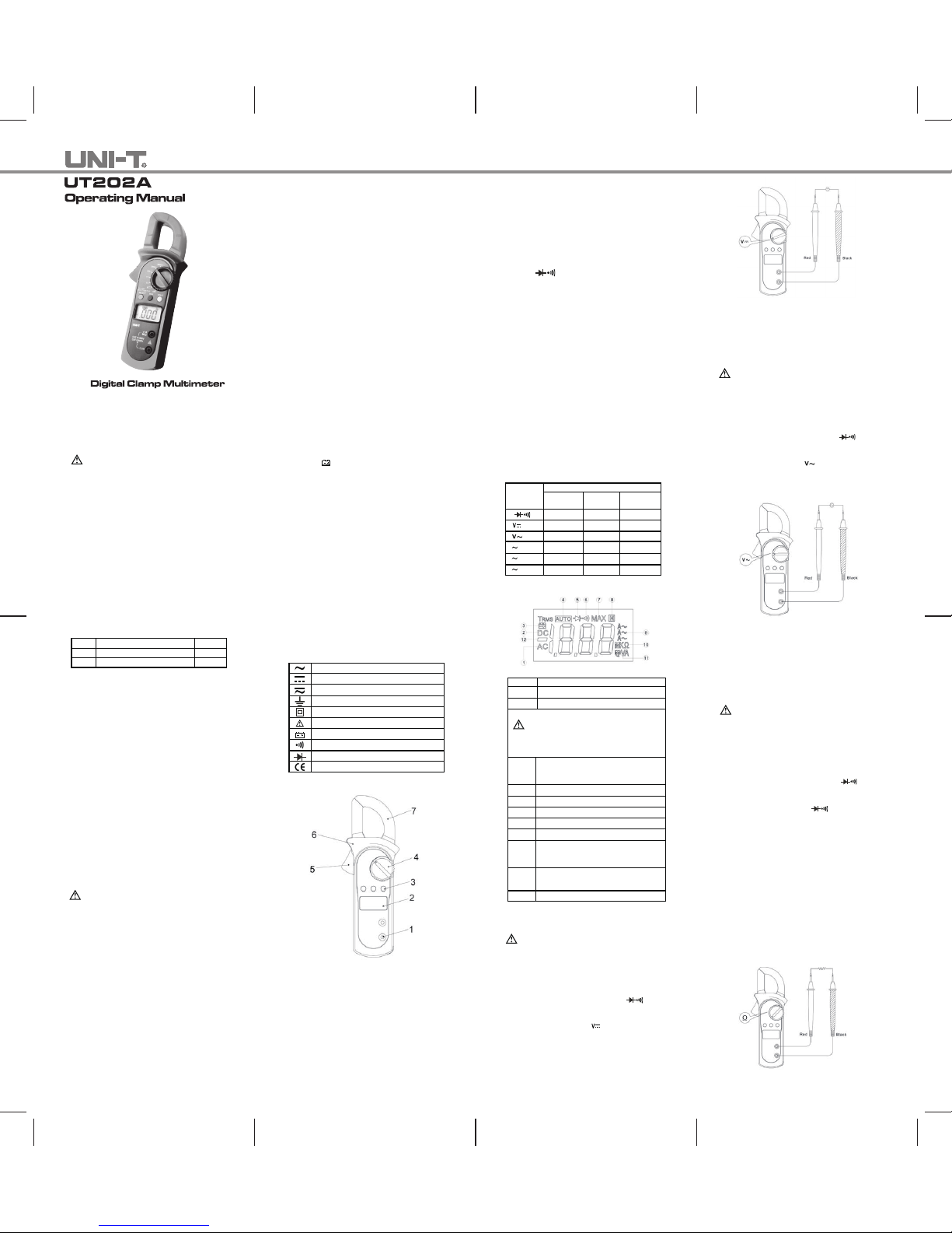
The Meter Structure (See Figure 1)
Figure 1
1. Input Terminals
2. LCD Display
3. Functional Buttons
4. Rotary Switch
5. Trigger: press the lever to open the
transformer jaws. When the pressure on the
lever is released, the jaws will close.
6. Hand Guards: to protect user’s hand from
touching the dangerous area.
7. Transformer Jaws: designed to pick up the
AC current flowing through the conductor.
It could transfer current to voltage. The
tested conductor must vertically go through
the jaw center.
maximum measurement position and reduce the
range step by step until a satisfactory reading is
obtained.
Functional Buttons and Auto Power Off
1. HOLD
Press HOLD to enter and exit hold mode. Press
and hold HOLD but ton w hile turnin g on the
Meter, auto power off will be canceled.
2. MAX
Press MAX to start record ing and updating of
maximum values.
3. SELECT
Under Ω ranging, resistance
measurement mode is default, press SELECT
to select continuity measurement mode or diode
measurement mode.
4. Auto Power Off
To preserve battery life, the Meter automatically
goes into a “sleep” mode if you do not press any
button for around 10 minutes. The Meter can be
activated by pressing any effective button (refer
to The E ffectiven ess o f Fun ctional Button s),
the n re turn to the disp lay for the funct ion
selected previously.
5. Buzzer
The buzz er sounds every time a eff ective button
is pressed down. When the meter will auto
power off in 1 minu te th e buzz er be eps f ive
times. Before power off there will be a long time
buzzer beeps.
6. The Effectiveness of Functional Buttons
Not every functional buttons can be use d on
eve ry r otary swi tch posit ions. B elow tabl e
describe w hich functional bu ttons can be used
on which rotary switch positions
Rotary Functional Buttons
Switch SELECT MAX HOLD
Positions
Ω • N/A •
N/A • •
N/A • •
A 20A N/A • •
A 200A N/A • •
A 600A N/A • •
Display Symbols (See Figure 2)
Number
Description
1 Indicator for AC voltage or current
2 Indicator for DC voltage
3 The battery is low.
Warning: To avoid false readings, which
could lead to possible electric shock or
personal injury, replace the battery as soon as
the battery indicator appears.
4 The Meter is in the auto range mode in
which the Meter automatically selects
the range with the best resolution.
5 Test of diode
6 The continuity buzzer is on
7 Maximum reading displayed
8 Data hold is active
9 Amperes (amps). The unit of current.
10 Ω: Ohm. The unit of resistance.
kΩ:Kilohm. 1000 ohms
MΩ:Megohm. 1,000,000 ohms
11 V: Volts. The unit of voltage.
mV: Millivolt. 0.001 volts
12 Indicates negative reading
Figure 2
Measurement Operation
A. Measuring DC Voltage (See Figure 3)
Warning
To avoid harm to you or damage to the Meter
from eletric shock, do not attempt t o measure
voltages higher than 600V AC/DC.
To measure D C voltage, conne ct the Meter as
follows:
1. Insert the red test lead into the
terminal and the black test lead into the
COM terminal.
2. Set the rotary switch to .
3. Connect the test leads across with the object
being measured.
VΩ
The measured value shows on the display.
Figure 3
Note:
Whe n D C v olta ge measu remen t h as been
completed, disconnect the connection b etween
the testing leads and the circuit under test and
remove testing leads from the input terminals.
B. Measuring AC Voltage (See Figure 4)
Warning
To avoid harm to you or damage to the Meter
from eletric shock, do not attempt t o measure
voltages higher than 600V AC/DC.
To measure AC voltage, conn ect the Met er as
follows:
1. Insert the red test lead into the
terminal and the black test lead into the
COM terminal.
2. Set the rotary switch to .
3. Connect the test leads across with the object
being measured.
The measured value shows on the display.
VΩ
Figure 4
Note:
Whe n A C v oltag e measu reme nt has bee n
completed, disconnect the connection b etween
the testing leads and the circuit under test and
remove testing leads from the input terminals.
C. Measuring Resistance (See Figure 5)
Warning
To avo id dama ge to th e M eter o r t o the
devices under test, disconnect circuit power and
discharge all the high-voltage capacitors before
measuring resistance.
To measure resistance , connect the Me ter as
follows:
1. Insert the red test lead into the
terminal and the black test lead into the
COM terminal.
2. Set the rotary switch to ; resistance
measurement (Ω) is default or press
SELECT button to select Ω measurement
mode
3. Connect the test leads across with the object
being measured.
The measured value shows on the display.
Note:
● Separating the objects being tested fr om
the ci rcuit when measuring can obtain a more
accurate result.
Ω
VΩ
Figure 5
● When resistan ce measuremen t has b een
completed, disconnect the connection b etween
the testing leads and the circuit under test and
remove testing leads from the input terminals.
Page 2
P/N:110401104343X
~ END ~
This operating manual is subject to change without notice.
To test the di ode out of a circuit, connect t he
Meter as follows:
1. Insert the red test lead into the
terminal and the black test lead into the
COM terminal.
2. Set the rotary switch to and press
SELECT button to select measurement
mode.
3. For forward voltage drop readings on any
semiconductor component, place the red
test lead on the component’s anode and
place the black test lead on the component’s
cathode.
Ω
VΩ
Note:
● Separating the objects being tested fr om
the ci rcuit when measuring can obtain a more
accurate result.
● When diode testing h as been completed,
disconnect the connection between the te sting
leads and the circuit under test and remove
testing leads from the input terminals.
E. Testing for Continuity (See Figure 7)
Warning
To avo id dama ge to th e M eter o r t o the
devices under test, disconnect circuit power and
discharge all the high-voltage capacitors before
measuring continuity.
To t est for c ontinu ity, c onnect the Mete r as
follows:
1. Insert the red test lead into the
terminal and the black test lead into the
COM terminal.
VΩ
Figure 6
Ω
Figure 7
2. Set the rotary switch to and press
SELECT button to select measurement
mode.
3. The buzzer sounds if the resistance of a
circuit under test is less than 10Ω.
4. The buzzer may or may not sounds if the
resistance of a circuit under test is more than
10Ω.
Note:
When continuity testing has be en comple ted,
disconnect the connection between the te sting
leads and the circuit under test and remove
testing leads from the input terminals.
F. Measuring AC Current (See Figure 8)
Warning
To avoid electric shock, never measure current
while the test l eads are i nserted into the input
terminals and disconnect test leads and tested
circuit connection.
Never attempt an in-circuit current measurement
wher e th e ope n-circu it v oltage betw een t he
circuit and the ground is greater than 600V
Us er pr ope r fun cti on, a nd ran ge fo r the
measurement.
otherwise it will casue deviation. The Meter
can only measure one conductor at a time,
to meausre more than one condutor at a
time will cause deviation.
Note:
When current measurement has been
completed,disconnect the connection between
the conductor under test and the jaw, and
remove the conductor away from the
transformer jaw of the Meter.
Figure 8
General Specifications
● Display: 3 1/2 digits LCD display, Maximum
display 1999
● Auto Polarity Display
● Overloading: Display OL or –OL
● Low Battery Indication: Display
●
Measurement Speed: Updates 3 times/second.
● Measuremnet Deviation: When the
conductor being meaured is not placed in a
correct position during AC current
measurement, it will cause ±3% reading
deviation.
● Drop Test: 1 meter drop test passed
● Max. Jaw Opening: 28mm diameter
● Max. Tested Current Conductor:
26mm diameter.
● Power: 9V battery
● Sleep Mode (can be disabled)
● Dimensions: 76mm x 208mm x 30mm.
●
Weight: Approximate 260g (battery included)
● The Meter is suitable for indoor use.
● Altitude: Operating: 2000m
Storage: 10000m
● Safety/ Compliances: IEC 61010 CATII
600V, CATIII 300V and Double Insulation
● Pollution degree: 2
● Temperature and humidity:
Operating: 0℃~30℃ (≤75%R.H);
30℃~40℃ (≤70%R.H);
40℃~50℃ (≤45%R.H);
Storage: -20℃~+60℃ (≤75%R.H)
Accuracy Specifications
Accuracy: ±(a% reading + b di gits), guarantee
for 1 year.
Operating temperature: 23℃±5
℃
Relative humidity: ≤75%R.H
Temperature coefficient: 0.1×(specified
accuracy) /1℃
A. AC Voltage: Auto Ranging
Range Resolution Accuracy
2.000V 1mV
20.00V 10mV ±(1.2%+5)
200.0V 100mV
600V 1V ±(1.5%+5)
Remarks:
● Overload protection:600V rms
● Input impedance: 10MΩ // <100pF
● Displays RMS value of sine wave (mean
value response).
● Frequency response: 40Hz~400Hz.
B. DC Voltage: Auto Ranging
Range Resolution Accuracy
200.0mV 0.1mV ±(0.8%+3)
2.000V 1mV
20.00V 10mV ±(0.8%+1)
200.0V 100mV
600V 1V ±(1%+3)
Remarks:
● Input impedance: 10MΩ
● Overload protection: 600V rms
C. Resistance: Auto Ranging
Range Resolution Accuracy
200.0Ω 100mΩ ±(1.2%+2)
2.000kΩ 1Ω
20.00kΩ 10Ω ±(1%+2)
200.0kΩ 100Ω
2.000MΩ 1kΩ ±(1.2%+2)
20.00MΩ 10kΩ ±(1.5%+2)
Remark:
● Overload protection: 600Vp
D. Continuity
Range Resolution Accuracy
Around <10Ω,the
buzzer beeps.
Remark:
● Overload Protection: 600Vp
● Open circuit voltage approximate 0.45V.
● The buzzer may or may not beeps when the
resistance of a circuit under test is more
than 10Ω.
E. Diode
Range Resolution Accuracy
Display approximate
forward voltage drop
Remarks:
● Overload Protection: 600Vp
● Open circuit voltage approximate 1.48V.
1mV
100mΩ
F. AC Current: Auto Ranging
Range Resolution Accuracy
20.00A 0.01A ±(2.0%+5)
200.0A 0.1A ±(1.5%+5)
600A 1A ±(2.0%+8)
Remarks:
● Overload protection: 600A rms
● Frequency Response: 50Hz~60Hz
● Displays RMS value of sine wave (mean
value response).
● To adjust reading in accordance with
RMS value.
Maintenance
Th is sect ion pr ovi des bas ic mai nte nanc e
inf orma tion in clud ing bat tery re plac emen t
instruction.
Warning
Do not attempt to repair or service your Meter
unle ss y ou a re qu alifie d to do so and have
the re levant calibration, performance test, and
service information.
To a void elect rical shoc k or dam age to t he
Meter, do not get water inside the case.
A. General Service
● Periodically wipe the case with a damp cloth
and mild detergent. Do not use abrasives or
solvents.
● To clean the terminals with cotton bar with
detergent, as dirt or moisture in the
terminals can affect readings.
● Turn the Meter power off when it is not in
use.
● Take out the battery when it is not using for
a long time.
● Do not use or store the Meter in a place
of humidity, high temperature, explosive,
inflammable and strong magnetic field.
To measure current, do the following:
1. Set the rotary switch to 20A ,200 A or
600 A .
2. Press the trigger to open the transformer jaws.
3. Center the conductor within the transformer
jaw, then release the Meter slowly until the
trasnformer jaw is completely closed, Make
sure the conductor to be tested is placed
at the center of the transformer jaw,
D. Testing Diodes (See Figure 6)
Warning
To avo id dama ge to th e M eter o r t o the
devices under test, disconnect circuit power and
discharge all the high-voltage capacitors before
testing diodes.
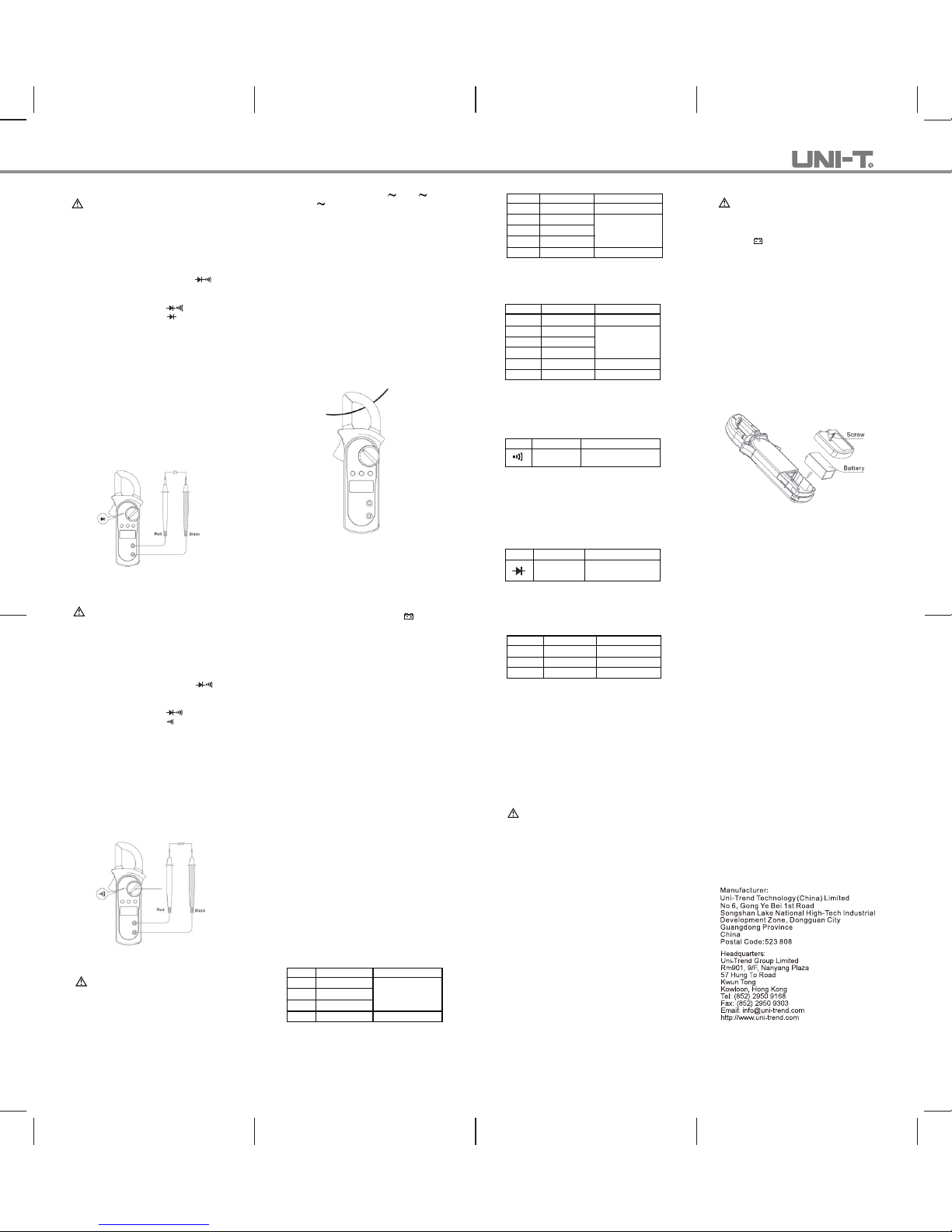
rep lace the bat tery as soon as the bat tery
indicator “ ” appears.
Make sure the trans former jaw and the tets
leads are discon ected from t he cir cuit being
tested before opening the case bottom.
To replace the battery:.
1. Turn the Meter off and remove all the
connections from the input terminals.
2. Turn the Meter’s case top down.
3. Remove the screw from the battery
compartment, and separate the battery
compartment from the case bottom.
4. Remove the old battery from the battery
compartment.
5. Rejoin the case bottom and the battery
compartment, and reinstall the screw.
Figure 9
B. Replacing the Battery (See Figure 9)
Warning
To avoid f alse rea ding s, which co uld lea d
to possible elect ric sh ock or perso nal in jury,
 Loading...