

Page 1
The test leads can add 0.1Ω to 0.3Ω of error to resistance
measurement.
For high-resistance measurement(>1MΩ), it is normal
taking several seconds to obtain a stable reading.
In each range, the Meter has an input impedance of 10 KΩ
This loading effect can cause measurement errors in high
impedance circuits. If the circuit impedance is less than or
equal to 10kΩ, the error is negligible (0.1 or less).
When DC voltage measurement has been completed,
disconnect the connection between the testing leads and
the circuit under test and remove testing leads from the
input terminals.
Do not apply more than the rated voltage, as marked
on the Meter, between the termials or between any
terminal and grounding. If the value to be measured is
unknown, use the maximum range and reduce the range
step by step until a satisfactory reading is obtained.
When measurement has been completed, disconnect
test leads from the circuits under test, remove the testing
leads away from the input terminals of the Meter and
turn the Meter power off.
The rotary switch should be placed in the right
position and no any changeover of range shall be made
during measurement to prevent damage of the Meter.
To avoid electric shock, do not carry out the
measurement when the Meter,s back case and battery
compartment are not closed.
Do not input higher than 600V between the Meter,s
terminals and the grounding to avoid electric shock
and damages to the Meter.
When the Meter working at an effective voltage over
60V in DC or 30V rms in AC, special care should be
taken for there is danger of electric shock.
Use the proper terminals, function, and range for
your measurements.
Do not use or store the Meter in an environment of
high temperature, humidity, explosive, inflammable and
strong magnetic field. The performance of the Meter
may deleriorate after dampened.
When using the test leads, keep your fingers behind
the finger guards.
Disconnect circuit power and discharge all high
behind the finger guards.
Disconnect circuit power and discharge all high
-voltage capacitors before testing resistance, continuity
and diode.
Replace the battery as soon as the battery indicator
appears. Whith a low battery, the Meter might produce
false readings that can lead to electric shock and
personal injury
When servicing the Meter, use the replacement parts
with the same model or identical electrical specifications.
To avoid any damage to the meter or any accident,
do not alter the internal circuit of the Meter randomly.
Soft cloth and mild detergent should be used to clean
the surface of the Meter when servicing. No abrasive
and solvent should be used to prevent the surface of
the Meter from corrosion, damage and accident.
The Meter is suitable for indoor use.
Turn the Meter off when it is not in use and take out
the battery when not using for a long time.
Constantly check the battery as it may leak when it
has been used for some time, replace the battery as
soon as leaking appears. A leaking battery will damage
the Meter.
Probe assemblies to be used for MAINS measurements
shall be RATED as appropriate for MEASUREMENT
CATEGORY III according to IEC 61010-031 and shall have
a voltage RATING of at least the voltage of the circuit to
be measured.
(See Figure 5)
International Electrical Symbols
The Meter Structure
(See Figure 1)
1. Input Terminals
2. LCD Display
3. Functional Buttons
4. Rotary Switch
5. Trigger: Push/release it
to open/close the clamp jaw.
6. Hand Guards: to protect user’s
hand from touching
the
7. Transformer Jaws: designed to pick up the AC current
flowing through the conductor. It could transfer current
to voltage.
( Figure 1)
Rotary Switch
Rotary
Switch
Position
Function
AC/DC voltage measurement.
: Diode test.
: Resistance measurement.
Power is turned off.OFF
: Continuity test.
Temperature measurement
(UT202 only)
o
C
o
F
AC current measurement range from 0.001A
to 400.0A
A
Functional Buttons
Below table indicated for information about the functiona l
button operations.
Press HOLD to enter and exit the
Hold mode in any mode, the Meter beeps.
Press and hold HOLD button
while turning on the Meter to display
full icons.
HOLD
MAX Press MAX to start recording and updating
of maximum values.
SELECT Press SELECT button to switch between
and .
oCo
F
Model: UT202
Rotary Switch
Positions Functional Buttons
SELECT MAX HOLD
V
V
N/A
N/A
N/A
N/A
A
A
2/20A N/A
200/400A N/A
oFo
C(K-Type)
The Effectiveness of Functional Buttons
Model: UT201
Rotary Switch
Positions Functional Buttons
SELECT MAX HOLD
V
V
N/A
N/A
N/A N/A
N/A
A
A
2/20A N/A
200/400A N/A
Display Symbols
(See Figure 2)
No. Symbol Description
3
The battery is low.
Warning: To avoid false readings,
which could lead to possible electric
shock or personal injury, replace
the battery as soon as the battery
indicator appears.
4
The Meter is in the auto range mode
in which the Meter automatically selects
the range with the best resolution.
5
Test of diode.
6
The continuity buzzer is on.
7
Date hold is active.
8
1 AC Indicator for AC voltage or current
2 DC Indicator for DC voltage
MAX Maximum reading displayed
The unit of temperature:
o
C: Centigrade temperature
o
F: Fahrenheit temperature
o
C
o
F
9
: Ohm. The unit of resistance.
k : kilohm.1 x 10
3
or 1000 ohms.
M : Megaohm. 1 x 10
6
or
1,000,000 ohms.
,k ,M
10
11 A Amperes (amps). The unit of current.
mV, V Volts. The unit of voltage.mV: Millivolt.
1x10
-3
or 0.001 volts
12
13
Indicates negative reading
14
OL The input value is too large for the
selected range
Measurement Operation
Warning
To avoid harms to you or damages to the Meter from
eletric shock, do not attempt to measure voltages higher
than 600V AC/DC, although readings may be obtained.
red black
( Figure 3)
V
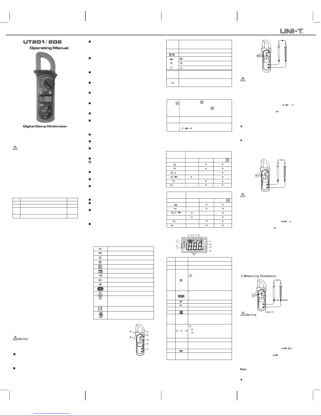
A. Measuring DC Voltage (See Figure 3)
B. Measuring AC Voltage (See Figure 4)
red black
( Figure 4)
Warning
The AC Voltage ranges are:
2.000V, 20.00V, 200.0V and 600V.
To measure AC voltage, connect the Meter as follows:
1. Insert the red test lead into the terminal and
the black test lead into the COM terminal.
2. Set the rotary switch to .
3. Connect the test leads across with the object being measured.
V
V
The measured value shows on the display.
dangerous area.
AC (Alternating Current).
DC (Direct Current).
AC or DC.
Grounding.
Double Insulated.
Continuity Test.
Diode.
Fuse.
Warning. Refer to the Operating Manual.
Conforms to Standards of European Union.
Capacitance Test
Deficiency of Built-In Battery
4007682
This symbol signify the product comply
with both USA and Canada requirement.
Before using the Meter inspect the case. Do not use
the Meter if it is damaged or the case (or part of the case)
is removed. Look for missing plastic. Pay attention to
the insulation around the connector.
Inspect the test leads for damaged insulation or
exposed metal. Check the test leads for continuity.
Replace damaged test leads with identical model number
or electrical specifications before using the Meter.
Overview
This Operating Manual covers information on safety and
cautions. Please read the relevant information carefully and
observe all the Warnings and Notes strictly.
Warning
To avoid electric shock or personal injury , read the
“Safety Information” and carefully before using the Meter.
Model UT201/202(hereafter referred to as "the Meter") is
2000-count stable, safe and reliable digital clamp multimeter.
It is designed with large-scale integrated circuits and A/D
converter as the core as well as the overload protection and
novel structure, which make it a superb tool for electricians.
The Meter can measure AC/DC voltage, AC current,
resistance, temperature(℉/℃), diode, continuity and so on.
In the event you find any missing or damaged part, please
contact your dealer immediately.
Unpacking Inspection
Open the package case and take out the Meter. Check
the following items carefully for any missing or damaged patr:
Point Contact Temperature Probe
(UT202 only)
4 1.5V Battery (AAA) 2 pcs
Item
1
2
3
Description
English Operating Manual
Test Lead
Qty
1 pc
1 pair
1 pc
Safety Information
This Meter complies with the standard EN 61010-1,
61010-2-032,61010-2-033,Pollution Degree 2, Measurement
category. (CAT II 600V,CAT III 300V) and Double Insulation.
ETL/ cETL: Conforms to UL STD 61010-1, 61010-2-032
and 61010-2-033
Certified to CSA STD C22.2 NO.61010-1, IEC STD
61010-2-032, IEC STD 61010-2-033
CAT II (MEASUREMENT CATEGORY II): Applicable to
test and measuring circuits connected directly to utilization
points (socket outlets and similar points) of the low-voltage
MAINS installation.
Examples are measurements on MAINS CIRCUITS of
household appliances, portable tools and similar equipment.
CAT III (MEASUREMENT CATEGORY): Applicable to
test and measuring circuits connected to the distribution
part of the building’s low-voltage MAINS installation.
Examples are measurements on distribution boards
(including secondary electricity meters), circuitbreakers,
wiring, including cables, bus-bars, junction boxes, switches,
socket-outlets in the fixed installation, and equipment for
industrial use and some other equipment such as stationary
motors with permanent connection to the fixed installation.
Use the Meter only as specified in this operating manual,
otherwise the protection provided by the Meter may be impaired.
In this manual, a Warning identifies conditions and actions
that pose hazards to the user, or may damage the Meter or
the equipment under test.
A Note identifies the information that user should pay
attention to.
To avoid pssible electric shock or personal injury,
andto avoid possible damage to the Meter or to the
equipment under test, adhere to the following rules:
Below tabel indicated for information about the rotary
switch positions.
Application around and removal from
UNINSULATED HAZARDOUS LIVE
conductors is permitted.
Not every functional buttons can be use on every rotary
switch positions.Below two tables describe on which rotary
position functional buttons can be valid accordingly.
The DC Voltage ranges are:
200.0mV, 2.000V, 20.00V, 200.0V and 600V.
To measure DC voltage, connect the Meter as follows:
1. Insert the red test lead into the terminal and
the black test lead into the COM terminal.
2. Set the rotary switch to .
3. Connect the test leads across with the object being measured.
The measured value shows on the display.
V
Note
To avoid harms to you or damages to the Meter from
eletric shock, do not attempt to measure voltages higher
than 600V AC/DC, although readings may be obtained.
Note
In each range, the Meter has and input impedance
of 10 MΩ. This loading effect can cause measurement
errors in high impedance circuits. If the circuit impedance
is less than or equal to 10 KΩ, the error is negligible
(0.1 or less).
When AC voltage measurement has been completed,
disconnect the connection between the testing leads
and the circuit under test and remove testing leads
from the input terminals.
T
o avoid harms to you, do not attempt to input voltages
higher than 60V DC or 30V rms AC.
To avoid damages to the Meter or to the devices under
test, disconnect circuit power and discharge all the
high-voltage capacitors before measuring resistance.
The resistance ranges are:
200.0Ω,2.000KΩ,20.00KΩ,200KΩ,2.000MΩ and 20.00MΩ
To measure resistance,connect the Meter as follows:
1. Insert the red test lead into the terminal and
the black test lead into the COM terminal.
2. Set the rotary switch to it, defaults at resistae(Ω)
-nce mod or press SELECT button to select Ω mode.
3. Connect the test leads across with the object being measured.
The measured value shows on the display.
Page 2
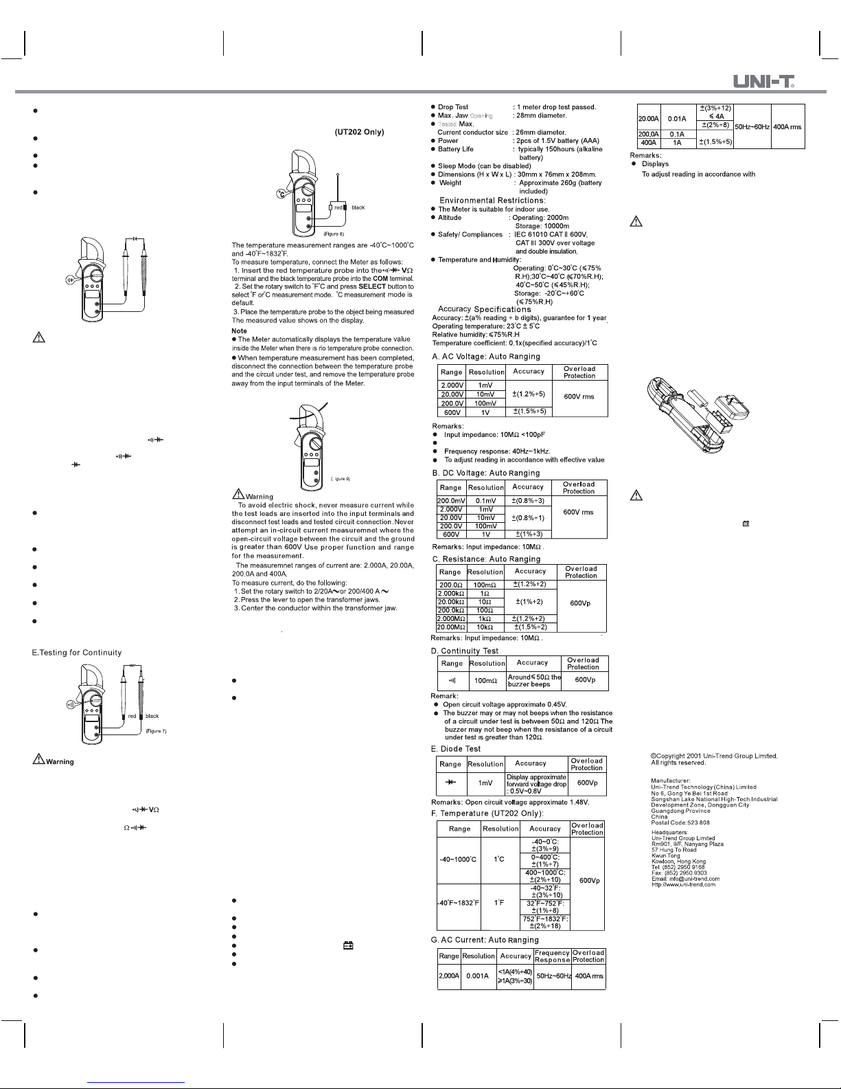
1. General Specifications:
Maximum voltage including transient overvoltage between
any terminals and grounding:500V rms
Display: Maximum display 1999
Auto Polarity Display
Overloading : Display OL or - OL
Low Battery Indication : Display
Measurement Speed : Updates 3 times/second
Measuremnet Deviation:
When the conductor being meaured
is not placed in a correct position
during AC current measurement,
current measurement, it will cause
±1% reading deviation.
To obtain accurate reading, measure only one conductor
at each time.
When current measurement has been completed, disconnect
the connection between the conductor under test and the
jaw, and remove the conductor away from the transformer
jaw of the Meter.
The buzzer beeps once when pressing any buttons at any
rotary switch positions except at 2/20A positions if the button
is valid. If the button is not valid, it does not beep. At 2/20A
rotary switch position, the buzzer is set not to beep.
The buzzer beep 5 times continuously on around 1 minute
before entering the sleep mode. When it is just before entering
the sleep mode, it will have one long beep to warn you.
The LCD displays OL indicating the circuit being tested
is open.
When continuity testing has been completed, disconnect
In a circuit, a good diode should still produce a forward
voltage drop reading of 0.5V to 0.8; however, the reverse
voltage drop reading can vary depending on the resistance
of other pathways between the probe tips.
Connect the test leads to the proper terminals as said
above to avoid error display.
The LCD will display OL indicating either open circuit or
wrong polarity connection.
The unit of diode is volt(V), displaying the forward voltage
drop readings.
Measuring the tested object that is already removed from
the in-line circuit can help to obtain a more accutate reading.
When diode testing has been completed, disconnect the
connection between the testing leads and the circuit under
test and remove testing leads from the input terminals.
If Ω reading with shorted test leads is not≤0.5Ω, check
for loose test leads, wrong function selected, or enabled
data hold function.
The LCD displays OL indicating open-circuit or the teste
resistor value is higher than the maximum range of the Meter
Resistance measurement is default to auto range mode.
Measuring the tested object that is already removed
from the in-line circuit can help to obtain a more accu-rate
reading.
When resistance measurement has been completed,
disconnect the connection between the testing leads and
the circuit under test and remove testing leads from the
input terminals.
(See Figure 8)
(See Figure 7)
F. Measuring Temperature
G. Measuring AC Current
D.Testing Diodes
(See Figure 6)
Warning
To avoid damages to the Meter or to the devices under
test, disconnect circuit power and discharge all the
high-voltage capacitors before testing diodes.
Use the diode test to check diodes, transistors, and other
semiconductor devices. The diode test sends a current
through the semicondutor junction, then measure the
voltage drop across the junction. A good silicon junction
drops between 0.5V and 0.8V.
To test the diode out of a circuit, connect the Meter as
follows:
1. Insert the red test lead into the terminal and
V
the black test lead into the COM terminal.
2. Set the rotary switch to and press SELECT button
to select measurement mode.
red black
( Figure 6)
then
Specifications
Maintenance
This section provides basic
maintenance information including
battery replacement instruction.
Warning
A
. General Service
B. Replacing the Battery (See Figure 10)
Do not attempt to repair or service your Meter unless
you are qualified to do so and have the relevant calibration,
performance test, and service information. To avoid
electrical shock or damage to the Meter,do not get water
nside the case.
Periodically wipe the case with a damp cloth and mild
detergent. Do not use abrasives or solvents.
To clean the terminals with cotton bar with detergent,
as dirt or moisture in the terminals can affect readings.
Turn the Meter power off when it is not in use.
Take out the battery when it is not using for a long time.
Do not use or store the Meter in a place of humidity,
high temperature, explosive, inflammable and strong
magnetic field.
( Figure 10)
Screw
Warning
To avoid false readings, which could lead to possible
electric shock or personal injury, replace the battery
as soon as the battery indicator “ ” appears.
Make sure the transformer jaw and the tets leads are
disconected from the circuit being tested before
opening the case bottom.
To replace the battery:.
1.Turn the Meter off and remove all the connections
from the input terminals
2. Turn the Meter’s case top down.
3. Remove the screw from the battery compartment,
and separate the battery compartment from the case
bottom.
4. Remove the old battery from the battery compartment.
5. Replace the battery with 2pcs of new 1.5V (AAA)
battery.
6. Rejoin the case bottom and the battery compartment,
and reinstall the screw.
** END **
This operating manual is subject to change without notice.
F
Opening
Tested
H
Display sinewave RMS( AVG response)
sinewave RMS (AVG response)
RMS value
(See Figure 9)
2.
3.
REV.1
DATE:2015-12-04
P/N:110401105587X
3. For forward voltage drop readings on any semiconductor
component, place the red test lead on the component,s
anode and the black test lead on the component,s cathode.
Note
To avoid damages to the Meter or to the devices under
test, disconnect circuit power and dicharge all the
high-voltage capacitors before measuring continuity.
To test for continuity,connect the Meter as follows:
1. Insert the red lead into the terminal and the
black test lead into the
COM
terminal.
2. Set the rotary switch to and press
SELECT
button to select measurement mode.
3. The buzzer sounds if the resistance of a circuit under
test is less than 50 Ω.
4. The buzzer may or may not sounds if the resistance of
a circuit under test is between 50 Ω to 120 Ω.
5. The buzzer does not sound if the resistance of a circuit
under test is higher than 120Ω.
Note
the connection between the testing leads and the circuit under
test and remove testing leads from the input terminals.
release the Meter slowly until the transformer jaw is completely
closed, Make sure the conductor to be tested is placed at
the center of the transfor- mer jaw, otherwise it will casue
deviation.
4. The measured value shows on the display,it is a effective
value of sine wave (mean value response).
Note
Sleep Mode
To preserve battery life, the Meter automatically turns off
if you do not turn the ratary switch or press any button for
around 15 minutes.
The Meter can be activated by turning the rotary switch
or pressing any button with the following conditions:
1) When the Meter enters Sleep Mode at temperature
functions of Model: UT202, the Meter cannot be activated
by turning the rotary switch to AC current ranges.
2)
Pressing any button must be according to“ The effectiveness
of Functional Buttons” section.
3) The Hold function will be cancelled if the Meter is activated
by pressing the
HOLD
button.
To disable the Sleep Mode function, Press and hold
HOLD
button while turning on the Meter.
 Loading...