

UNI-T UT107 Operating Manual

Table of Contents
Title Page
1
3
4
4
5
7
9
10
11
11
12
13
13
13
15
17
19
21
23
24
25
26
27
28
29
30
31
31
32
32
33
Model UT107: OPERATING MANUAL
Overview
Unpacking Inspection
Safety Information
Rules For Safe Operation
Automotive Servicing Safety Guide
International Electrical Symbols
The Meter Structure
Rotary Switch
Functional Buttons
Display Symbols
Measurement Operation
Part 1 Multimeter Basic Testing
A. DC Voltage Testing
B. AV Voltage Testing
C. DC Current Testing
D. Resistance Testing
E. Diode Testing
F. Continuity Testing
G. 12V Battery Measurement
H. Temperature Measurement
I. Frequency Measurement
J. Measuring Duty Cycle
K. Dwell Testing
L. Engine Tach (Rotation Speed)
Testing “RPMx10”
M. Operation of Hold Mode
Part 2 Diagnosis of Automotive Troubles
A. Fuse Testing: Check the fuse to see if
it is blown out
B. Switch Testing: Check the switch to see
if it can work correctly
C. Solenoid or Relay Testing
D. Starting/Charging System Testing

Title Page
2
Model UT107: OPERATING MANUAL
34
35
36
38
39
39
40
41
42
43
44
45
46
48
48
49
51
53
54
54
54
55
55
55
56
56
56
57
57
57
58
59
59
60
61
E. Battery Power Consumption Testing
when the Engine Is off
F. Trigger Voltage Battery Load Testing
G. Voltage Drop Testing
H. Charging System Voltage Testing
I. Ignition System Testing
1. Ignition Coil Testing
2. Ignition System High Voltage Damper Testing
3. Hall Switch/Sensor Testing
4. Magnetic Resistance Sensor
5. RPMx10 Testing
6. Fuel System Testing
J. Engine Sensor Testing
1. Oxygen Sensor
2. Temperature Sensor
3. Position Sensor
4. Absolute Pressure (MAP) and Baro Sensor
5. Mass Air Flow (MAF) Sensor
General Specifications
Accurate Specifications
A. DC Voltage
B. AC Voltage
C. DC Current
D. Resistance
E. Diode
F. Continuity T esting
G. 12V Battery
H. Temperature
I. Frequency
J. Duty Cycle
K. Dwell Testing
L. Tach (Rotation Speed) Testing
Maintenance
A. General Services
B. Replacing the Fuses
C. Replacing the Battery

Overview
3
Model UT107: OPERATING MANUAL
This Operating Manual covers information on safety and
cautions. Please read the relevant information carefully
and observe all the Warnings and Notes strictly.
Warning
To avoid electric shock or personal injury, read the
“Safety Information” and “Rules for Safe Operation”
carefully before using the Meter.
Automotive Digital Multimeter Model UT107 (hereafter
referred to as “the Meter”) is a 1999 counts, 3-1/2 digits
manual ranging meter. Spotting a unique design with
an extra large LCD display , Connect Test Leads display ,
full overload protection and unique outlook design. For
this reason, it emerges as an electric meter with more
outstanding performance for safer operation than other
meters. In addition to the Dwell, Tach and Data Hold
feature, the Meter can be used to test the AC voltage,
DC voltage, DC current, resistance, temperature, battery ,
duty cycle, frequency, diode and continuity.

This Meter complies with standards IEC61010: in pollution
degree 2, overvoltage category (CAT. II 1000V, CAT. III
600V) and double insulation.
CA T.II: Local level, appliance, PORTABLE EQUIPMENT
etc., with smaller transient overvoltages than CAT. III
CAT.III: Distribution level, fixed installation, with smaller
transient overvoltages than CAT. IV
Use the Meter only as specified in this operating manual,
otherwise the protection provided by the Meter may be
impaired.
International electrical symbols used on the Meter and
in this Operating Manual are explained on page 9.
Unpacking Inspection
In the event you find any missing or damage, please
contact your dealer immediately.
Open the package case and take out the Meter. Check
the following items carefully to see any missing or
damaged part:
4
Item
Description
Qty
Model UT107: OPERATING MANUAL
English Operating Manual
Test Lead
Point Contact Temperature Probe
Holster
9V Battery (NEDA 1604, 6F22 or 006P)
1 piece
1 pair
1 piece
1 piece
1 piece
1
2
3
4
5
Safety Information

5
Model UT107: OPERATING MANUAL
Rules For Safe Operation
Warning
To avoid possible electric shock or personal injury,
and to avoid possible damage to the Meter or to the
equipment under test, adhere to the following rules:
Before using the Meter inspect the case. Do not
use the Meter if it is damaged or the case (or part
of the case) is removed. Look for cracks or missing
plastic. Pay attention to the insulation around the
connectors.
Inspect the test leads for damaged insulation or
exposed metal. Check the test leads for continuity .
Replace damaged test leads with identical model
number or electrical specifications before using
the Meter.
When using the test leads, keep your fingers
behind the finger guards.
Do not apply more than the rated voltage, as
marked on the Meter, between the terminals or
between any terminal and grounding.
To avoid harm to yourselves, never attempt to
input an effective voltage over 60V in DC or 30V
in AC.
Use the proper terminals, function, and range for
your measurements.
The rotary switch should be placed in the right
position and no any changeover of range shall be
made during measurement is conducted to prevent
damage of the Meter.
Disconnect circuit power and discharge all highvoltage capacitors before testing, resistance,
diodes or continuity.
Before measuring current, check the fuse is ok.
Before connecting the Meter in serial to the tested
in-circuit, disconnect in-circuit power.
l
l
l
l
l
l
l
l
l

6
Model UT107: OPERATING MANUAL
l
l
l
l
l
l
l
l
l
If the value of current to be measured is unknown,
use the maximum measurement position, and
reduce the range step by step until a satisfactory
reading is obtained
Replace the battery as soon as the battery indicator
appears. With a low battery, the Meter might
produce false readings that can lead to electric
show and personal injury.
When servicing the Meter, use only the same
model number or identical electrical specifications
replacement parts.
The internal circuit of the Meter shall not be altered
at will to avoid damage of the Meter and any
accident.
Soft cloth and mild detergent should be used to
clean the surface of the Meter when servicing. No
abrasive and solvent should be used to prevent
the surface of the Meter from corrosion, damage
and accident.
Turn off the Meter when it is not in use and take
out the battery when not using for a long time.
Constantly check the battery as it may leak when
it has been using for some time, replace the battery
as soon as leaking appears. A leaking battery will
damage the Meter.
Do not use or store the Meter in an environment
of high temperature, humidity, explosive,
inflammable and strong magnetic field. The
performance of the Meter may deteriorate after
dampened.
The Meter is suitable for indoor use.

7
Model UT107: OPERATING MANUAL
Automotive Servicing Safety Guide
Warning
As some automobiles are installed with safety air
bags, you must pay attention to the cautions in the
automotive servicing manual when you are working
around the components and wiring of the air bags,
or any carelessness will open an air bag, resulting
in some personal injury. Note that the air bag will
also be opened for a few minutes after the ignition
lock is closed (or even when the automotive battery
is cut off), which is driven by the special energy
reserve.
Wear protective eyeglasses which meet safety
requirements.
Operate the automobile in a well-ventilated place so
as to prevent the inhalation of any toxic tail gas.
Keep your own tools and testing instruments far from
all the heater components of the operating engine.
Ensure that the automobile has stopped (automatic
transmission) or put into neutral gear (manual
transmission) and be sure that it is equipped with
brakes and the wheels have been locked.
Do not place any tool on the automotive battery which
will cause a short circuit of the electrodes and in turn
lead to any personal injury or damage to a tool or
battery .
Smoking or striking a light near the automobile is
prohibited.
Pay attention to ignition coil, an ignition lead or a
spark plug socket because these components are
provided with high voltages when the automobile is
operating.
T o connect or cut off an electronic component, close
the ignition lock.
Pay attention to the automotive producer’s cautions,
notes and servicing procedures.
l
l
l
l
l
l
l
l
l
To prevent an accident from causing any personal
injury or any damage to an automobile or any of its
meters, please read the following safety guidelines
and testing procedure in earnest:

8
Model UT107: OPERATING MANUAL
A. The data of the automotive servicing manual have
originated from the automotive servicing information.
Contact the local distributors of automotive components.
Contact the local retailers of automotive components.
Contact the local libraries to look up any book for the
proofreading of your automotive servicing manual so as
to provide you with the latest information.
1.
2.
3.
B. Before the diagnosis of any trouble, open the
engine hood to make a thorough visual inspection.
Y ou will find the causes for many of your problems
to be solved, which will save you a lot of time.
Has the automobile recently been serviced? Has the
same problem sometimes occurred where the trouble
lies?
Do not try to find any short cut. Check the hoses and
leads where it is probably very difficult to find out
where any trouble lies.
Check any trouble with the air purifier or pipeline
system.
Check any damage to any sensor or the driving gear.
Check the ignition lead: any breakage of any terminal,
crack on any spark plug or breakage at the insulation
of the ignition lead.
Check all the vacuum hoses: any right line, shrinkage,
bend, crack, fracture or damage.
Check the leads: any connection of sharp edges,
connection of hot surfaces (such as exhaust manifold),
shrinkage, burn or scratch at the insulation or right
line connection.
Check circuit connections: any pin corrosion, bend or
damage, inappropriate connection position or damaged
electrode lead.
1.
2.
3.
4.
5.
6.
7.
8.
All the information, explanations and detailed
descriptions in the operation manual have originated
from the industrial information recently published.
It is impossible to prove the accuracy and
completeness of the information, of which we shall
not be responsible for the assumption.
International Electrical Symbols
AC (Alternating Current).
DC (Direct Current)
Grounding.
Double Insulated.
Deficiency of Built-In Battery.
Fuse.
Warning. Refer to the Operating Manual.
Conforms to Standards of European Union.
9
Model UT107: OPERATING MANUAL
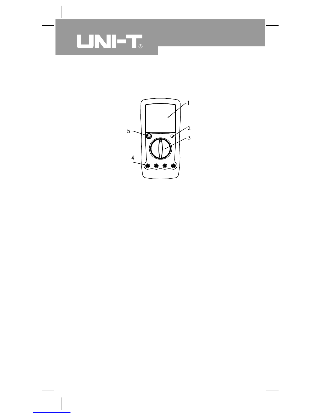
The Meter Structure (see figure 1)
1. LCD display 2.Data Hold button
3. Rotary Switch 4. Input Terminals
5. Power button
(figure 1)
10
Model UT107: OPERATING MANUAL
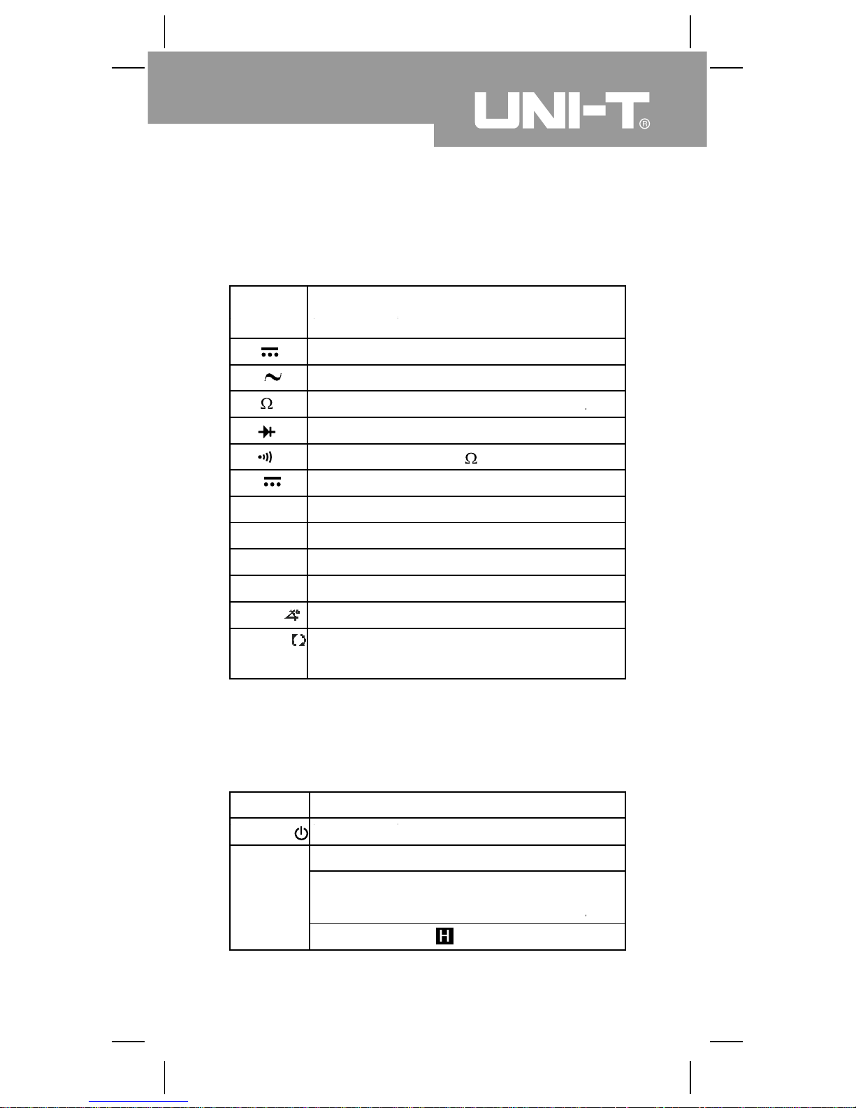
Rotary Switch
Rotary
Switch
Position
Function
V
kHz
0
C
A
DWELL
RPM x 10
DC Voltage Measurement.
AC Voltage Measurement.
Resistance Measurement.
Diode Test.
Continuity Test, Unit:
DC Current Measurement.
Battery Measurement
Temperature Measurement, Unit: 0C
Frequency Measurement, Unit: Kilohertz
Duty Cycle Measurement
Automotive ignition dwell testing, Unit: degree
Automotive engine tach testing (Displayed
Reading x 10), Unit: rpm
Functional Buttons
Button
Operation Performed
POWER
HOLD
Turn the power on and off.
Press HOLD once to enter hold mode.
Press HOLD again to exit hold mode and
the present value is shown.
In Hold mode, is displayed
12V
Duty%
11
Model UT107: OPERATING MANUAL
Below table indicated for information about the rotary
switch positions.
Below table indicated for information about the functional
button operations.
l
l
l
V
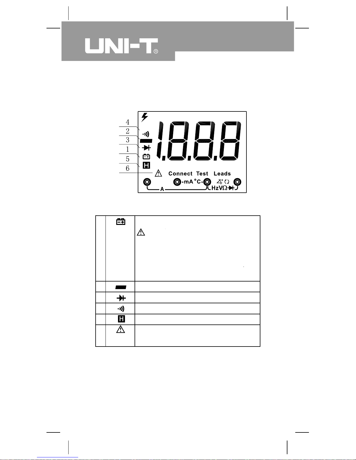
Display Symbols (see figure 2)
The battery is low.
Warning: To avoid false readings,
which could lead to possible electric
shock or personal injury, replace the
battery as soon as the battery indicator
appears.
Indicates negative reading.
Test of diode.
Continuity test.
Date hold is active.
Indicator of connecting test leads into
different input terminals.
( figure 2)
12
Model UT107: OPERATING MANUAL
1
2
3
4
5
6
Connect
test leads
V
13
Model UT107: OPERATING MANUAL
Measurement Operation
Part 1 Multimeter Basic Testing
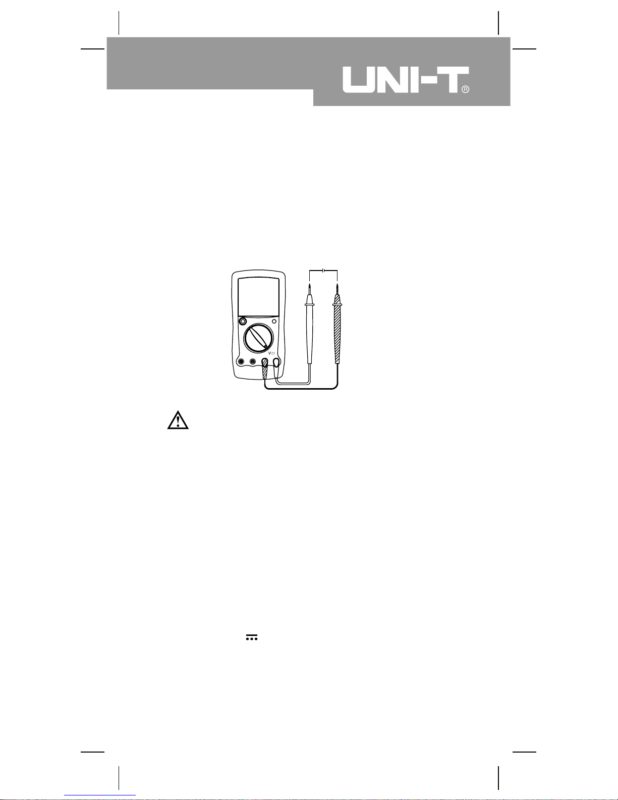
A. DC Voltage Testing (see figure 3)
( figure 3)
Warning
T o avoid harms to you or damages to the Meter from
electric shock, please do not attempt to measure
voltages higher than 1000Vp although readings may
be obtained.
Please take extra care when measuring high voltages
to avoid electric shock.
Insert the red test lead into the V terminal and the
black test lead into the COM terminal.
Set the rotary switch to an appropriate measurement
position in .
Connect the test leads across with the object being
measured.
The measured value shows on the display.
1.
2.
3.
The DC voltage ranges are: 200mV, 2V, 20V, 200V and
1000V.
To measure DC voltage, connect the Meter as follows:

Note
14
Model UT107: OPERATING MANUAL
If the value of voltage to be measured is unknown,
use the maximum measurement position (1000V) and
reduce the range step by step until a satisfactory
reading is obtained.
The LCD displays “1” indicating the existing selected
range is overloaded, it is required to select a higher
range in order to obtain a correct reading.
In each range, the Meter has an input impedance of
approx. 10M . This loading effect can cause
measurement errors in high impedance circuits. If the
circuit impedance is less than or equal to 10k , the
error is negligible (0.1% or less).
When DC voltage measurement has been completed,
disconnect the connection between the testing leads
and the circuit under test.
l
l
l
l
15
Model UT107: OPERATING MANUAL
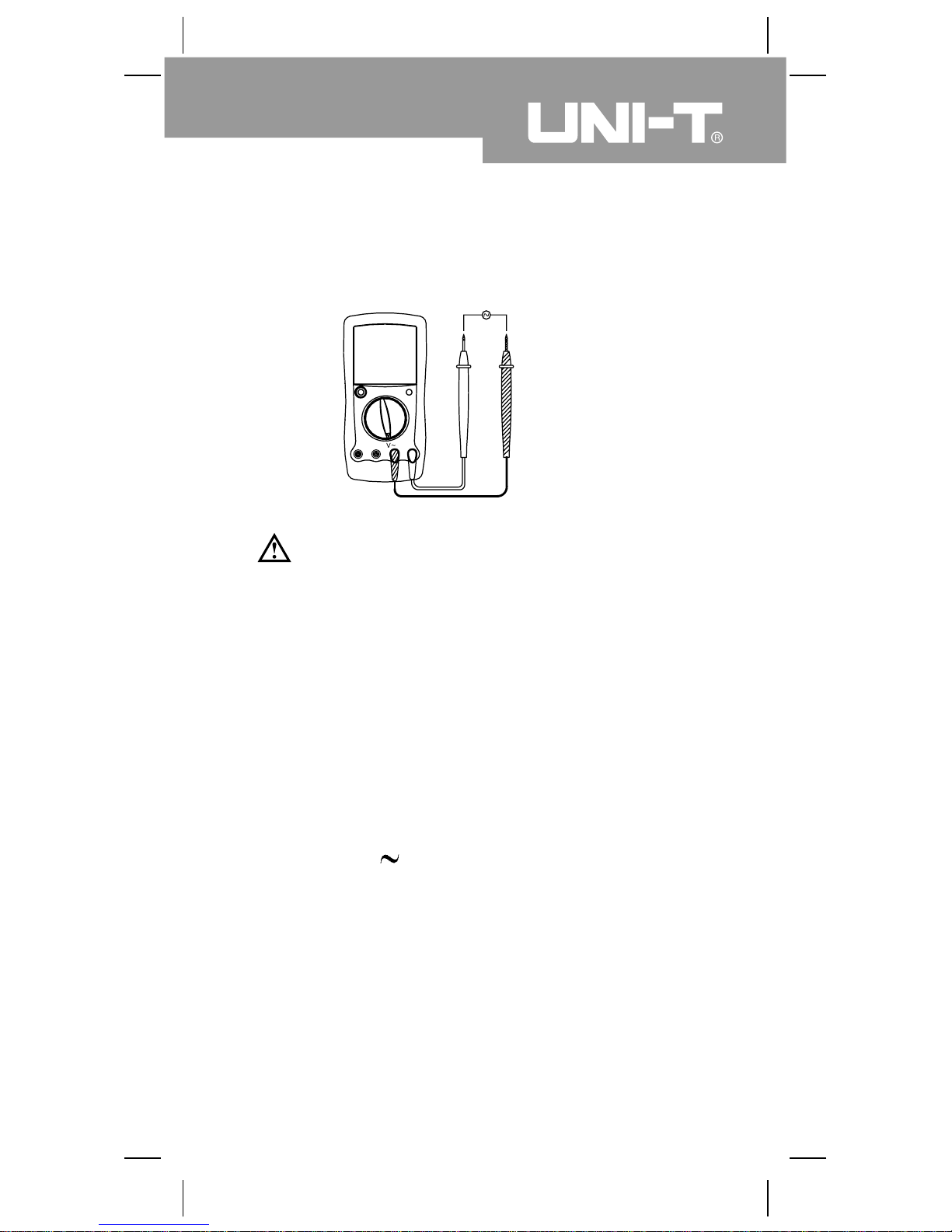
B. AC Voltage Testing (see figure 4)
( figure 4)
Warning
T o avoid harms to you or damages to the Meter from
electric shock, please do not attempt to measure
voltages higher than 1000Vp although readings may
be obtained.
Please take extra care when measuring high voltages
to avoid electric shock.
Insert the red test lead into the V terminal and the
black test lead into the COM terminal.
Set the rotary switch to an appropriate measurement
position in .
Connect the test leads across with the object being
measured.
The measured value shows on the display. It is the
effective value of sine wave (mean value response).
1.
2.
3.
V
The AC voltage ranges are: 200V and 750V.
To measure AC voltage, connect the Meter as follows:

Note
16
Model UT107: OPERATING MANUAL
If the value of voltage to be measured is unknown,
use the maximum measurement position (1000V) and
reduce the range step by step until a satisfactory
reading is obtained.
The LCD displays “1” indicating the existing selected
range is overloaded, it is required to select a higher
range in order to obtain a correct reading.
In each range, the Meter has an input impedance of
approx. 10M . This loading effect can cause
measurement errors in high impedance circuits. If the
circuit impedance is less than or equal to 10k , the
error is negligible (0.1% or less).
When AC voltage measurement has been completed,
disconnect the connection between the testing leads
and the circuit under test.
l
l
l
l
A
17
Model UT107: OPERATING MANUAL
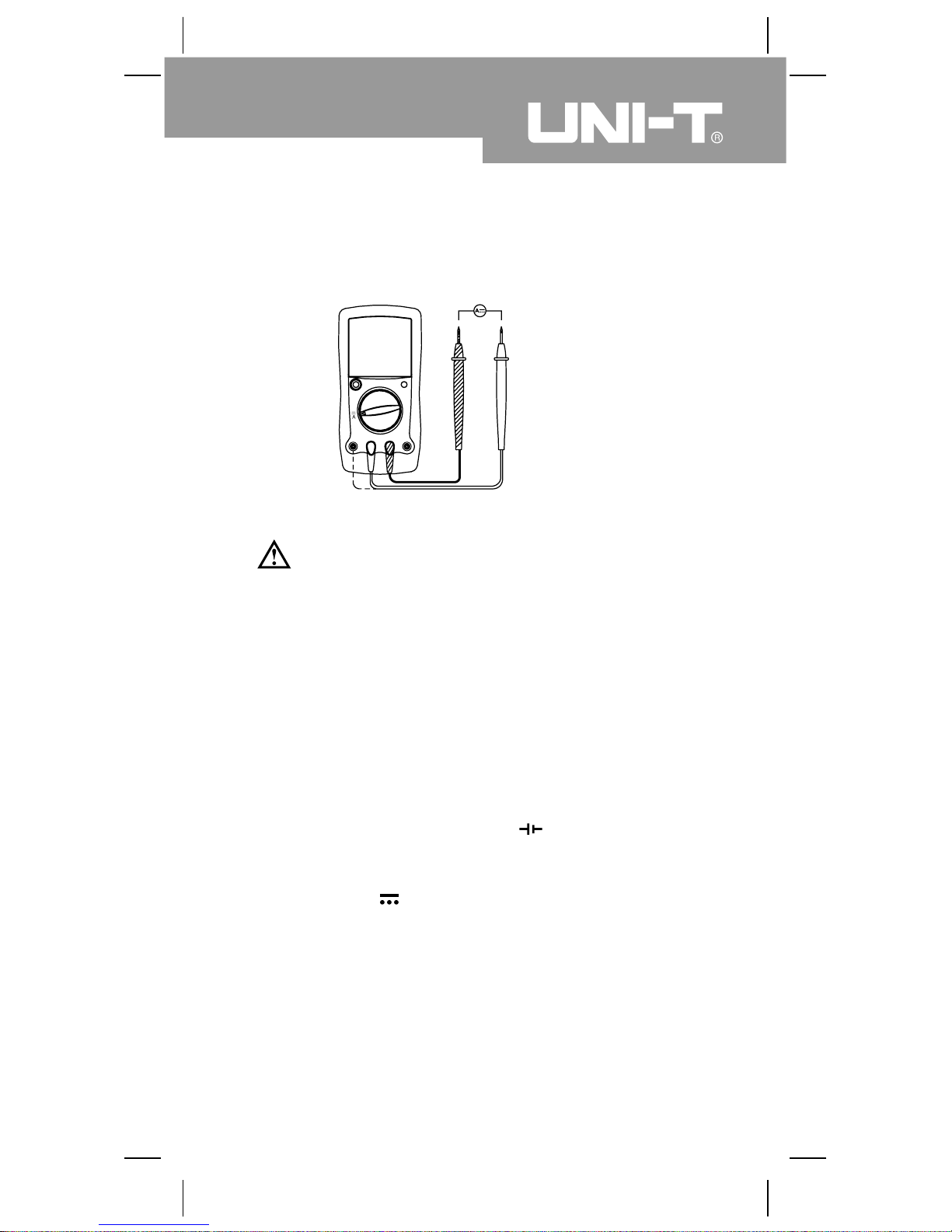
C. DC Current Testing (see figure 5)
Warning
Before connecting the Meter in serial to the tested
in-circuit, disconnect in-circuit power.
The current ranges are: 200mA and 10A.
Insert the red test lead into the mA0C or A terminal
and the black test lead into the COM terminal.
Set the rotary switch to an appropriate measurement
position in .
Connect the test leads in serial to the object being
measured.
The measured value shows on the display.
1.
2.
3.
( figure 5)
If the fuse burns out during measurement, the Meter
may be damaged or the operator himself may be
hurt. Use proper terminals, function, and range for
the measurement. When the testing leads are
connected to the current terminals, do not parallel
them across any circuit otherwise it will burn the
fuse or damage to the Meter.
To measure DC current, connect the Meter as follows:

Note
18
Model UT107: OPERATING MANUAL
If the value of current to be measured is unknown, use
the maximum measurement position (10A) and 10A
terminal, and reduce the range step by step until a
satisfactory reading is obtained.
When DC current measurement has been completed,
disconnect the connection between the testing leads
and the circuit under test.
When measuring 5A~10A: for continuous measurement
10 seconds and interval time between 2 measurement
greater than 15 minutes.
l
l
l
19
Model UT107: OPERATING MANUAL
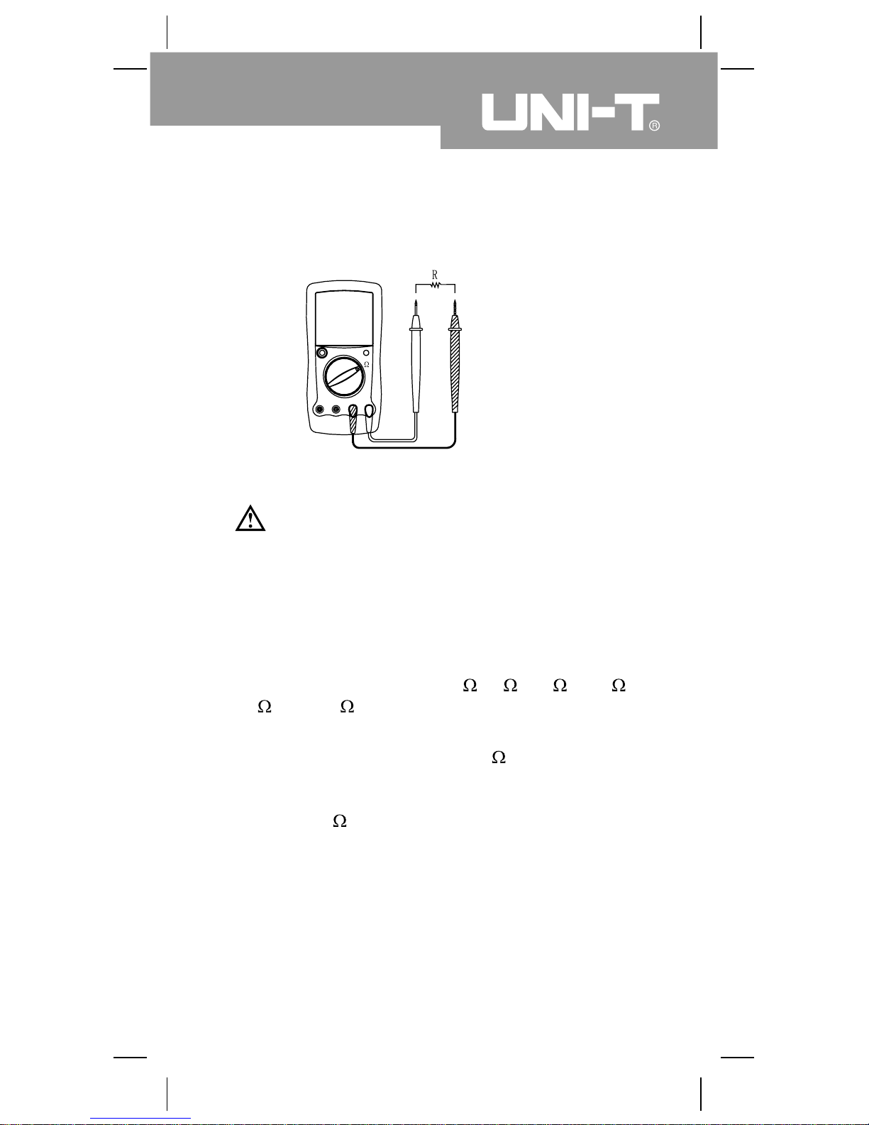
D. Resistance Testing (see figure 6)
( figure 6)
Warning
To avoid damages to the Meter or to the devices
under test, disconnect circuit power and discharge
all the high-voltage capacitors before measuring
resistance.
The resistance ranges are: 200 , 2k , 20k , 200k ,
2M and 20M .
Insert the red test lead into the terminal and the
black test lead into the COM terminal.
Set the rotary switch to an appropriate measurement
position in range.
Connect the test leads across with the object being
measured.
The measured value shows on the display.
1.
2.
3.
T o avoid harm to yourselves, never attempt to input
an effective voltage over 60V in DC or 30V in AC.
To measure resistance, connect the Meter as follows:
 Loading...