


Table of Contents
Title Page
Overview
Unpacking Inspection
Safety Information
Rules For Safe Operation
Automotive Servicing Safety Guide
International Electrical Symbols
The Meter Structure
Rotary Switch
Functional Buttons
Display Symbols
Measurement Operation
Part 1 Multimeter Basic Testing
A. AC and DC Voltage Testing
B. DC Current Testing
C. Resistance Testing
D. Diode Testing
E. Continuity Testing
F. Dwell Testing
G. Engine Tach (Rotation Speed)
Testing “RPMx10”
H. Data Holding
Part 2 Diagnosis of Automotive Troubles
A. Fuse Testing: Check the fuse to
see if it is blown out.
B. Switch Testing: Check the switch
to see if it can work correctly.
C. Solenoid or Relay Testing
D. Starting/Charging System Testing
E. Battery Power Consumption Testing
when the Engine Is off
F. Trigger Voltage Battery Load Testing
G. Voltage Drop Testing
Model UT105: OPERATING MANUAL
1
3
4
5
6
8
11
12
13
14
15
17
17
17
18
20
21
23
24
25
26
27
27
27
28
28
29
30
31

Title Page
H. Charging System Voltage Testing
I. Ignition System Testing
1. Ignition Coil Testing
2. Ignition System High Voltage
Damper Testing
3. Hall Switch/Sensor Testing
4. Magnetic Resistance Sensor
5. RPMx10 Testing
6. Fuel System Testing
J. Engine Sensor Testing
1. Oxygen Sensor
2. Temperature Sensor
3. Position Sensor
4. Absolute Pressure (MAP) and
Baro Sensor
5. Mass Air Flow (MAF) Sensor
General Specifications
Accurate Specifications
A. DC Voltage
B. AC Voltage
C. DC Current
D. Resistance
E. Diode
F. Continuity Testing
G. Dwell Testing
H. Tach (Rotation Speed) Testing
Maintenance
A. General Services
B. Replacing the Fuses
C. Replacing the Battery
33
34
34
35
36
37
38
39
40
41
43
44
45
47
49
50
50
50
50
51
51
51
52
52
53
53
53
54
Model UT105: OPERATING MANUAL
2

Overview
This Operating Manual covers information on safety and
cautions. Please read the relevant information carefully
and observe all the Warnings and Notes strictly.
Warning
To avoid electric shock or personal injury, read the
“Safety Information” and “Rules for Safe Operation”
carefully before using the Meter.
In 1999 counts and 3-1/2 digits, the UT105 Meter is a
manual testing automotive digital Multimeter. Spotting
a unique design with an extra large screen, this meter
has useful features such as a fully-functional symbol
display, connect prompt, and full testing overload
protection. For this reason, it emerges as an electric
Meter with more outstanding performance for safer
operation than other Meters. In addition to the automotive
dwell and tach (rotation speed), this Meter can be used
to test the AC voltage, DC voltage, DC current, resistance,
diode and continuity.
Model UT105: OPERATING MANUAL
3

Unpacking Inspection
In the event you find any missing or damage, please
contact your dealer immediately.
9V Battery (NEDA 1604, 6F22 or 006P)
Open the package case and take out the Meter. Check
the following items carefully to see any missing or
damaged part:
Model UT105: OPERATING MANUAL
4
Item
1
2
3
4
Description
English Operating Manual
Test Lead
Alligator Clip
Qty
1 piece
1 pair
1 pair
1 piece

Safety Information
This Meter complies with standards IEC61010: in pollution
degree 2, overvoltage category (CAT. II 1000V, CAT. III
600V) and double insulation.
CA T.II: Local level, appliance, PORTABLE EQUIPMENT
etc., with smaller transient overvoltages than CAT. III
CAT.III: Distribution level, fixed installation, with smaller
transient overvoltages than CAT. IV
Use the Meter only as specified in this operating manual,
otherwise the protection provided by the Meter may be
impaired.
International electrical symbols used on the Meter and
in this Operating Manual are explained on page 11.
Model UT105: OPERATING MANUAL
5

Rules For Safe Operation (1)
l Before using the Meter inspect the case. Do
not use the Meter if it is damaged or the case
(or part of the case) is removed. Look for cracks
or missing plastic. Pay attention to the insulation
around the connectors.
l Inspect the test leads for damaged insulation
or exposed metal. Check the test leads for
continuity. Replace damaged test leads with
identical model number or electrical specifications
before using the Meter.
l When using the test leads, keep your fingers
behind the finger guards.
l Do not apply more than the rated voltage, as
marked on the Meter, between the terminals or
between any terminal and grounding.
l When the Meter working at an effective voltage
over 60V in DC or 30V in AC, special care should
be taken for there is danger of electric shock.
l Use the proper terminals, function, and range
for your measurements.
l The rotary switch should be placed in the right
position and no any changeover of range shall
be made during measurement is conducted to
prevent damage of the Meter.
l Disconnect circuit power and discharge all
high-voltage capacitors before testing current,
resistance, diodes or continuity.
l Replace the battery as soon as the battery
indicator appears. With a low battery, the
Meter might produce false readings that can
lead to electric shock and personal injury.
To avoid possible electric shock or personal injury,
and to avoid possible damage to the Meter or to the
equipment under test, adhere to the following rules:
Warning
Model UT105: OPERATING MANUAL
6
Rules For Safe Operation (2)
Model UT105: OPERATING MANUAL
7
Model UT105: OPERATING MANUAL
8

l To connect or cut off an electronic component,
close the ignition lock.
l Pay attention to the automotive producer’s cautions,
notes and servicing procedures.
All the information, explanations and detailed
descriptions in the operation manual have originated
from the industrial information recently published.
It is impossible to prove the accuracy and completeness
of the information, of which we shall not be responsible
for the assumption.
A. The data of the automotive servicing manual have
originated from the automotive servicing information.
1. Contact the local distributors of automotive components.
2. Contact the local retailers of automotive components.
3. Contact the local libraries to look up any book for the
proofreading of your automotive servicing manual so as
to provide you with the latest information.
B. Before the diagnosis of any trouble, open the
engine hood to make a thorough visual inspection.
You will find the causes for many of your problems
to be solved, which will save you a lot of time.
1. Has the automobile recently been serviced? Has the
same problem sometimes occurred where the trouble
lies?
2. Do not try to find any short cut. Check the hoses and
leads where it is probably very difficult to find out where
any trouble lies.
3. Check any trouble with the air purifier or pipeline system.
4. Check any damage to any sensor or the driving gear.
Automotive Servicing Safety Guide(2)
Model UT105: OPERATING MANUAL
9

5. Check the ignition lead: any breakage of any terminal,
crack on any spark plug or breakage at the insulation
of the ignition lead.
6. Check all the vacuum hoses: any right line, shrinkage,
bend, crack, fracture or damage.
7. Check the leads: any connection of sharp edges,
connection of hot surfaces (such as exhaust manifold),
shrinkage, burn or scratch at the insulation or right line
connection.
8. Check circuit connections: any pin corrosion, bend or
damage, inappropriate connection position or damaged
electrode lead.
Automotive Servicing Safety Guide(3)
Model UT105: OPERATING MANUAL
10
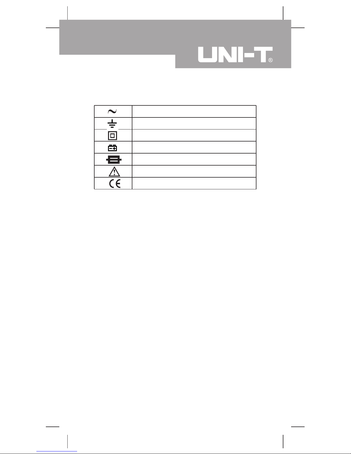
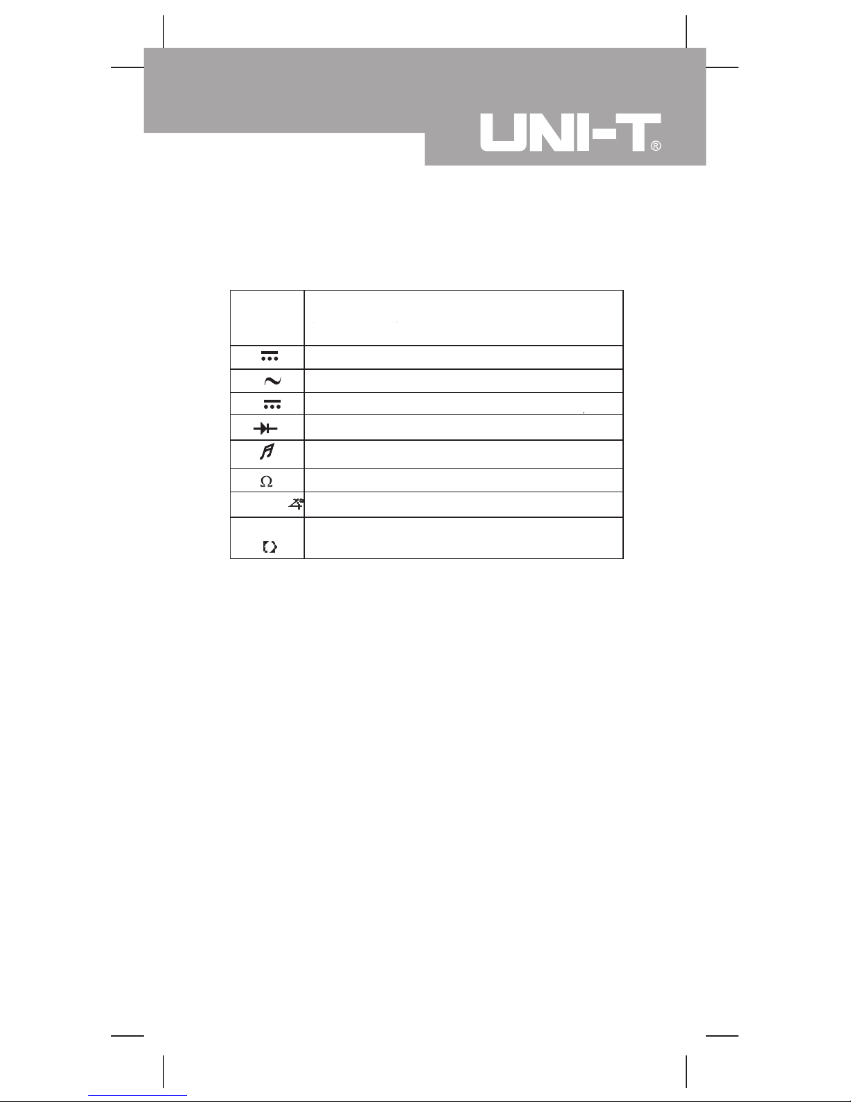
International Electrical Symbols
AC (Alternating Current).
Grounding.
Double Insulated.
Deficiency of Built-In Battery.
Fuse.
Warning. Refer to the Operating Manual.
Conforms to Standards of European Union.
Model UT105: OPERATING MANUAL
11
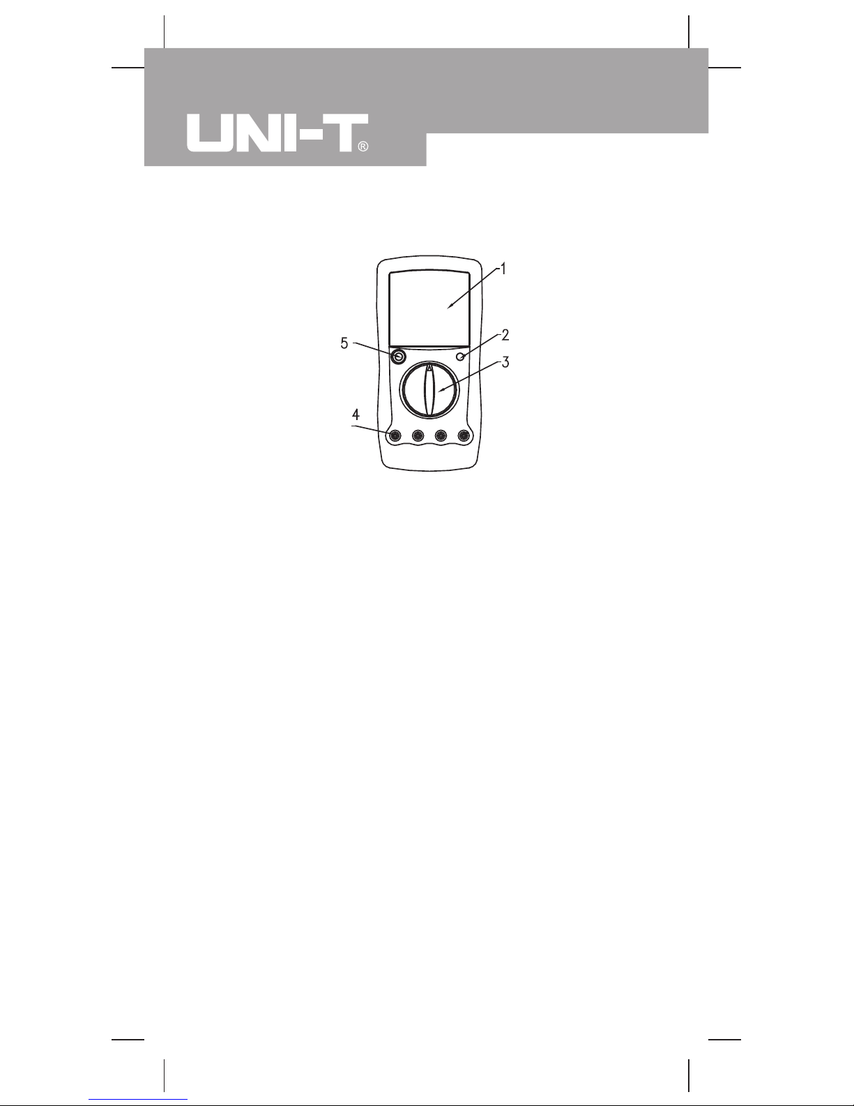
The Meter Structure (see figure 1)
1. LCD display
2. Data Hold button
3. Rotary Switch
4. Input Terminals
5. Power button
(figure 1)
Model UT105: OPERATING MANUAL
12
Rotary Switch
Rotary
Switch
Position
Function
DC voltage measurement.
AC voltage measurement.
DC Current Measurement
Diode test.
Continuity test.
Resistance measurement.
V
V
A
Automotive engine tach (rotation speed)
testing (Displayed Reading x 10), Unit: rpm
RPM x 10
DWELL Automotive ignition dwell testing, Unit: degree
Below table indicated for information about the rotary
switch positions.
Model UT105: OPERATING MANUAL
13
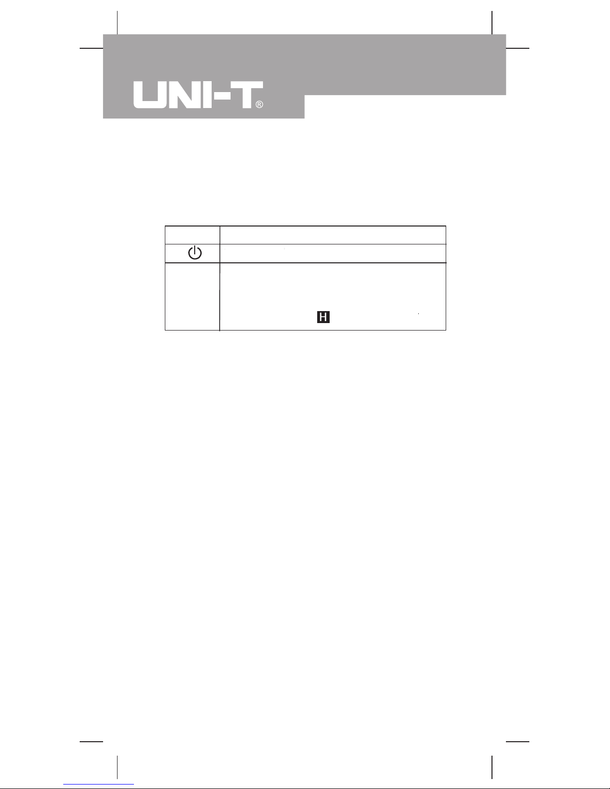
Functional Buttons
Below table indicated for information about the functional
button operations.
AC voltage measurement.
Turn the power on and off.
l Press HOLD once to enter hold mode.
l Press HOLD again to exit hold mode
and the present value is shown.
l In Hold mode, is displayed
HOLD
Model UT105: OPERATING MANUAL
14
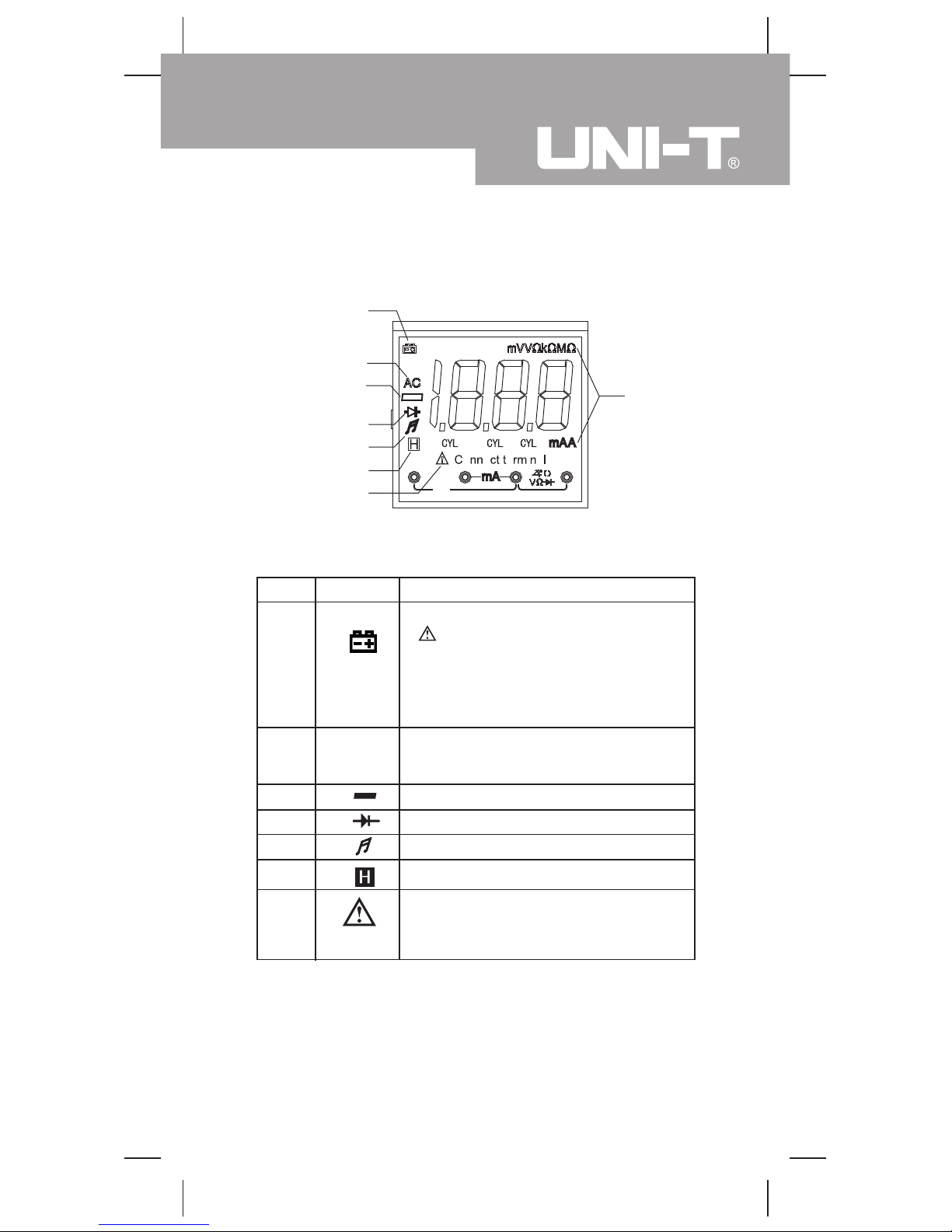
Display Symbols (see figure 2)
( figure 2)
No. Symbol Meaning
1
The battery is low.
Warning: To avoid false readings,
which could lead to possible electric
shock or personal injury , replace the
battery as soon as the battery
indicator appears.
2
Indicates negative reading.
4
Test of diode.
5
The continuity buzzer is on.
6
Date hold is active.
7
Indicator for AC voltage or current.
The displayed value is the mean
value.
3
AC
Connect
Terminal
Indicator of connecting test leads
into different input terminals.
Model UT105: OPERATING MANUAL
15
1
2
3
4
5
6
7
8
Display Symbols(2) (see figure 2)
Ω: Ohm. The unit of resistance.
kΩ: kilohm.1 x 103 or 1000 ohms.
MΩ: Megaohm. 1 x 10⁶ or
1,000,000 ohms.
mA, A
A: Amperes (amps). The unit of
current.
mA: Milliamp. 1 x 10⁻³ or 0.001
amperes.
V: Volts. The unit of voltage.
mV: Millivolt. 1 x 10⁻³ or 0.001 volts.
No. Symbol Meaning
8
Ω,kΩ,MΩ
mV, V
4CYL,
6CYL,
8CYL
DWELL Test of Dwell.
RPM x10 Tach x 10.
Number of cylinders.
Model UT105: OPERATING MANUAL
16
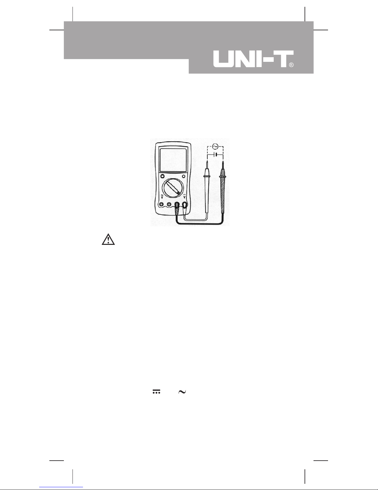
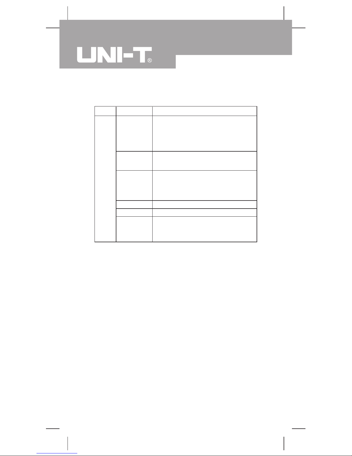
Measurement Operation(1)
Part 1 Multimeter Basic Testing
A.AC or DC Voltage Testing (see figure 3)
Warning
To avoid harms to you or damages to the Meter from
electric shock, please do not attempt to measure
voltages higher than 1000Vp although readings may
be obtained.
(figure 3)
The DC voltage ranges are: 200.0mV, 2.000V, 20.00V,
200.0V and 1000V.
The AC voltage ranges are: 2.000V, 20.00V, 200.0V and
750V
To measure DC or AC voltage, connect the Meter as
follows:
1. Insert the red test lead into the V terminal and the
black test lead into the COM terminal.
2. Set the rotary switch to an appropriate measurement
position in V . or V
3. Connect the test leads across with the object being
measured.
The measured value shows on the display.
Model UT105: OPERATING MANUAL
17
 Loading...