


UNION SWITCH & SIGNAL 


645 Russell Street
Batesburg, SC 29006
Service Manual 7063
R
Digitair Model 6696
End-of-Train
Communication Display Unit
Installation
Operation
October 1996
July 1997
COPYRIGHT 1995, UNION SWITCH & SIGNAL
PRINTED IN SA
1997 Union Switch & Signal Inc.
Printed in USA
An ANSALDO Affiliated Company
An Ansaldo Affilated Company

TABLE OF CONTENTS
SM 7063 07/97 |
ii |

|
|
TABLE OF CONTENTS |
I |
INTRODUCTION............................................................................................................. |
1-1 |
1.0 |
PURPOSE OF MANUAL................................................................................................. |
1-1 |
1.1 |
GENERAL OVERVIEW................................................................................................... |
1-1 |
1.1.1 |
CDU FUNCTIONAL DESCRIPTION .............................................................................. |
1-2 |
1.2 |
DEFINITION of TERMS ................................................................................................. |
1-2 |
1.3 |
PATENTS AND TRADEMARKS ..................................................................................... |
1-3 |
1.4 |
R.A.I.L. TEAM AND TECHNICAL SUPPORT................................................................. |
1-3 |
1.5 |
CDU ORDERING INFORMATION ................................................................................. |
1-3 |
1.5.1 Mounting and Hardware Options ...................................................................................... |
1-3 |
|
1.5.2 |
Parts Used for Installation ................................................................................................ |
1-4 |
1.5.3 |
Diagnostic Software Disk ................................................................................................. |
1-4 |
1.5.4 |
CDU Executable Software Disk ....................................................................................... |
1-4 |
1.6 |
CDU SPECIFICATIONS ................................................................................................. |
1-5 |
1.7 |
CDU MAJOR COMPONENTS ........................................................................................ |
1-6 |
1.7.1 |
CDU Unit Housing .......................................................................................................... |
1-6 |
1.7.2 |
CDU Rear Panel ............................................................................................................. |
1-7 |
1.7.3 |
CDU Major Assemblies .................................................................................................. |
1-8 |
1.8 |
CDU FUNCTIONAL BLOCK DIAGRAM ........................................................................ |
1-9 |
II |
INSTALLATION .............................................................................................................. |
2-1 |
2.0 |
INSTALLATION OF THE CDU ....................................................................................... |
2-1 |
2.1 |
General Description ......................................................................................................... |
2-1 |
2.2 |
Preparing the Locomotive ................................................................................................ |
2-1 |
2.2.1 |
Mounting Tray Installation ................................................................................................ |
2-1 |
2.2.2 |
AAR Clean Cab Enclosure .............................................................................................. |
2-2 |
2.3 |
Installing the CDU Cables ................................................................................................ |
2-2 |
2.3.1 |
Power Cable Installation .................................................................................................. |
2-2 |
2.3.2 |
Odometer (Axle Alternator) Cable Installation .................................................................. |
2-2 |
2.3.3 |
Antenna and Cable Installation ........................................................................................ |
2-4 |
2.3.4 |
CDU Datalogger Connector ............................................................................................. |
2-4 |
2.3.5 |
Event Recorder Connector .............................................................................................. |
2-4 |
2.4 |
MOUNTING THE CDU .................................................................................................... |
2-5 |
2.4.1 |
72 VDC / 12 VDC Power Selection Jumper (JP1) ............................................................ |
2-5 |
2.4.2 |
Installing the CDU onto a Mounting Tray .......................................................................... |
2-5 |
2.4.3 |
Installing the CDU into an AAR Clean Cab Enclosure ...................................................... |
2-5 |
2.5 |
BRIEF OPERATIONAL TEST OF THE CDU ................................................................... |
2-6 |
2.5.1 |
CDU Power-Up Sequence ............................................................................................... |
2-6 |
2.5.2 |
CDU Functional Check .................................................................................................... |
2-7 |
SM 7063 07/97 |
iii |
|
TABLE OF CONTENTS |
|
III |
OPERATION ................................................................................................................. |
3-1 |
3.0 |
CDU OPERATING INSTRUCTIONS ............................................................................. |
3-1 |
3.1 |
Purpose and Use of ID Code ......................................................................................... |
3-1 |
3.2 |
Radio Communication Channel ...................................................................................... |
3-1 |
3.3 |
DESCRIPTION of CDU FRONT PANEL DISPLAYS and CONTROLS ......................... |
3-2 |
3.4 |
DESCRIPTION of CDU DISPLAY SYSTEM .................................................................. |
3-2 |
3.4.1 |
Brake Pressure Display .................................................................................................. |
3-2 |
3.4.2 Message Receipt Indicator in Pressure Display .............................................................. |
3-3 |
|
3.4.3 |
ID Code Display .............................................................................................................. |
3-3 |
3.4.4 |
Function Menu Display ................................................................................................... |
3-4 |
3.4.5 |
LED Annunciators ........................................................................................................... |
3-5 |
3.4.6 |
ARMED Status LED (Optional) ...................................................................................... |
3-6 |
3.5 |
FUNCTION KEYS .......................................................................................................... |
3-7 |
3.6 |
EMERGENCY BRAKE SWITCH .................................................................................... |
3-8 |
3.7 |
SONALERT ................................................................................................................. |
3-8 |
3.8 |
OPERATION of CDU FUNCTION MENU ITEMS .......................................................... |
3-9 |
3.8.1 |
Viewing and Changing the ID Code ............................................................................... |
3-9 |
3.8.1.1 Operation if “Allow Changing Between One and Two Way ID Menu” is Enabled ........... |
3-9 |
|
3.8.1.2 Operation of Change ID Code Display if “Blank ID Menu During No Activity” |
|
|
|
is Enabled ............................................................................................................... |
3-11 |
3.8.2 |
Entering the Train Length ............................................................................................. |
3-11 |
3.8.3 |
Measuring Distance Traveled Using the Odometer (Count Up from Zero) ................. |
3-12 |
3.8.4 |
Using the Train Length Distance Function (Count Down to Zero) ............................... |
3-13 |
3.8.5 |
Calibrating the Odometer Using a Measured Mile ....................................................... |
3-14 |
3.8.6 |
Viewing the Locomotive Wheel Size ............................................................................ |
3-15 |
3.8.7 |
Changing the Locomotive Wheel Size from the Front Panel ........................................ |
3-15 |
3.8.8 |
Viewing Train Acceleration ........................................................................................... |
3-16 |
3.8.9 |
Viewing the Train Speed .............................................................................................. |
3-16 |
3.8.9.1 Setting and Using English or Metric Units .................................................................... |
3-16 |
|
3.8.10 |
Display Secondary Air Pressure ................................................................................... |
3-17 |
3.8.11 Disarming the CDU ...................................................................................................... |
3-18 |
|
3.8.12 |
Scanning for Incoming ID Codes .................................................................................. |
3-19 |
3.8.13 |
Setting the Sonalert Output Volume ............................................................................. |
3-19 |
3.8.14 |
Setting the Display Panel Brightness ........................................................................... |
3-19 |
3.8.15 Performing a CDU Self Test ......................................................................................... |
3-20 |
|
3.9 |
PERFORMING A LAMP TEST ..................................................................................... |
3-20 |
3.10 |
ARMING the CDU to an END UNIT ............................................................................. |
3-21 |
3.10.1 Description of Arming Process ..................................................................................... |
3-22 |
|
3.10.2 Automatic Arming ......................................................................................................... |
3-23 |
|
3.11 |
MOTION INDICATION ................................................................................................. |
3-23 |
3.12 |
ALARM INDICATIONS ................................................................................................. |
3-24 |
3.12.1 Low Battery .................................................................................................................. |
3-24 |
|
3.12.2 |
Rear-to-Front Communications Failure (R TO F FAILURE) ........................................ |
3-25 |
3.12.3 |
Front-to-Rear Communications Failure (F TO R FAILURE) ........................................ |
3-25 |
3.12.4 ALARM Annunciator ..................................................................................................... |
3-26 |
|
|
|
|
|
|
|
SM 7063 07/97 |
iv |
|

|
|
|
|
TABLE OF CONTENTS |
3.13 |
EMERGENCY BRAKE APPLICATION ........................................................................ |
3-27 |
||
3.14 |
COMMUNICATION TEST ............................................................................................ |
3-28 |
||
3.15 |
AUTOMATIC COMMUNICATION TEST ..................................................................... |
3-28 |
||
3.16 |
CDU DATALOGGER PORT ........................................................................................ |
3-29 |
||
3.16.1 |
Data Logger Format ..................................................................................................... |
3-29 |
||
3.16.2 Event Recorder Format ................................................................................................ |
3-32 |
|||
3.16.2.1 |
Electrical Characteristics ........................................................................................... |
3-32 |
||
3.16.2.2 |
Data Transfer Protocol .............................................................................................. |
3-32 |
||
IV |
CONFIGURATION and DIAGNOSTICS ....................................................................... |
4-1 |
||
4.0 |
CONFIGURATION and DIAGNOSTICS ........................................................................ |
4-1 |
||
4.1 |
Diagnostic Software ........................................................................................................ |
4-1 |
||
4.1.1 |
Running the Diagnostic Software ................................................................................... |
4-1 |
||
4.2 |
Main Menu ...................................................................................................................... |
|
4-2 |
|
4.3 |
Diagnostic Items ............................................................................................................. |
4-3 |
||
4.4 |
Configuration Items Menu .............................................................................................. |
4-3 |
||
4.4.1 |
Set ID Code ... |
4-4 |
|
|
4.4.2 |
Set One-Way Protocol .................................................................................................... |
4-5 |
||
4.4.3 |
Set Two-Way Protocol .................................................................................................... |
4-6 |
||
4.4.4 |
Enable Two-Way Mode .................................................................................................. |
4-7 |
||
4.4.5 |
Set Low Pressure Threshold .......................................................................................... |
4-8 |
||
4.4.6 |
Configure Odometer ....................................................................................................... |
4-9 |
||
4.4.6.1 Set Type of Units Submenu............................................................................................. |
4-9 |
|||
4.4.6.2 Set Wheel Diameter Submenu ..................................................................................... |
4-10 |
|||
4.4.7 |
Configure Data Logger ................................................................................................. |
4-11 |
||
4.4.7.1 |
Set Protocol ... |
4-11 |
|
|
4.4.7.2 |
Set Baud Rate |
.............................................................................................................. |
4-12 |
|
4.4.7.3 |
Set Bits Per Character .................................................................................................. |
4-12 |
||
4.4.7.4 |
Set Parity ....... |
4-13 |
|
|
4.4.7.5 Set Number of Stop Bits ............................................................................................... |
4 -13 |
|||
4.4.8 |
Configure Armed Status LED ....................................................................................... |
4-14 |
||
4.4.9 |
Configure Customer String ........................................................................................... |
4-15 |
||
4.4.10 |
Configure Front Panel Menu ........................................................................................ |
4-16 |
||
4.4.11 |
Enable Automatic Arming ............................................................................................. |
4-17 |
||
4.4.12 |
Set Transmit Power Level ............................................................................................ |
4-18 |
||
4.4.13 |
Allow Changing Between One and Two Way Operation............................................... |
4-19 |
||
4.4.14 |
Blanking the Function Menu Display During No Activity ............................................... |
4-20 |
||
SM 7063 07/97 |
v |

|
|
TABLE OF CONTENTS |
APPENDIX A SOFTWARE UPGRADES .................................................................................. |
A-1 |
|
A.1 |
CDU Software Upgrades ................................................................................................ |
A-1 |
A.2 |
Cab Unit Flash Loader Program ..................................................................................... |
A-1 |
A.3 |
Using “load.exe” ............................................................................................................. |
A-1 |
A.4 |
Procedure for Downloading CDU Software Upgrades ................................................... |
A-2 |
|
LIST OF FIGURES & ILLUSTRATIONS |
|
Figure 1-0 Two-Way Telemetry .................................................................................................. |
1-1 |
|
Figure 1-1 |
Model 6696 CDU Features & Front Panel Layout .................................................... |
1-6 |
Figure 1-2 |
Model 6696 CDU Features (Rear Panel View) ........................................................ |
1-7 |
Figure 1-3 Model 6696 CDU Features (Top Internal View) ....................................................... |
1-8 |
|
Figure 1-4 CDU Model 6696 Functional Block Diagram ............................................................ |
1-9 |
|
Figure 3-1 CDU Model 6696 Front Panel Layout ....................................................................... |
3-2 |
|
Figure 3-2 Arming Process ....................................................................................................... |
3-21 |
|
|
LIST OF TABLES |
|
Table 1-1 |
Installation Parts ......................................................................................................... |
1-4 |
Table 1-2 Diagnostic Software Diskette .................................................................................... |
1-4 |
|
Table 1-3 |
CDU Specifications .................................................................................................. |
1-5 |
Table 2-1 CDU Power Connections............................................................................................ |
2-2 |
|
Table 2-2 CDU Axle Alternator Connections (Bayonet Twist Lock Type Connector) ................... |
2-3 |
|
Table 2-3 CDU Axle Alternator Connections (MS Threaded Type Connector) ............................ |
2-3 |
|
Table 2-4 CDU DATALOGGER Port Connections ..................................................................... |
2-4 |
|
Table 2-5 CDU Event Recorder Connections ............................................................................ |
2-4 |
|
Table 3-1 Quick Reference: CDU Function Menus and Display Messages ............................. |
3-4 |
|
Table 3-2 Quick Reference: CDU Annunciator LEDs ............................................................... |
3-5 |
|
Table 3-3 |
Quick Reference: CDU Function Keys .................................................................... |
3-7 |
Table 3-4 English or Metric Units ........................................................................................... |
3-16 |
|
SM 7063 07/97 |
vi |

SECTION I INTRODUCTION
1.0PURPOSE OF MANUAL
This manual provides general information on the DIGITAIR End-of-Train Telemetry System and detailed information on the installation and operation of the Model 6696 Communication Display Unit (CDU). Refer to Service Manual SM 7064 for detailed Shop Maintenance information.
1.1GENERAL OVERVIEW
The DIGITAIR End-of-Train Telemetry System consists of a Communication Display Unit (CDU) mounted in the locomotive cab which communicates via UHF radio with an end-of-train End Unit mounted on the coupler of the last train car.
The CDU, when operating in conjunction with an End Unit such as the DIGITAIR Model 6695 SBU, provides the locomotive operator with information about the conditions at the rear of the train that are important to the operation of the train. The CDU’s major functions include:
A digital display of the brake pipe pressure at the rear of the train.
An indication of motion of the last car (moving/stopped) and its initial direction (forward/reverse).
The End Unit battery status and other warnings about brake pipe pressure.
The On/Off status of the Highly Visible Marker (HVM) light if equipped on the End Unit.
When operating in two-way mode, provides an Emergency braking function from the rear of the train.
The CDU can be configured to support optional functions such as:
A digital display of the auxiliary pressure if transmitted by dual pressure type End Units.
A built-in odometer to display the distance traveled by the locomotive, speed, and/or acceleration.
The CDU Model 6696 is compatible with all End Units employing existing protocols such as the American Association of Railroads (AAR) End-of-Train message protocol. It meets or exceeds the guidelines of the AAR along with the Federal Railroad Administration (FRA), the Federal Communications Commission (FCC), Industry Canada (IC), and the Canadian Department of Communications (DOC) regulations.
LOCOMOTIVE
LAST CAR
450UHF-475RFMHzLINKRF LINK |
END UNIT |
|
-BRAKE PRESS. |
VEHICLE |
|
|
||
|
|
-BATTERY STATUS |
|
|
|
BATT. |
|
HVM |
|
-HVM STATUS |
|
BRAKE PIPE AIR |
ODOMETER CDU 6696 |
||
|
-CAR MOTION |
INPUT (OPT.) |
|
|
|
-COMMS LINK TEST -EMERGENCY ACTIVATION
Figure 1-0. Two-Way Telemetry Functions
SM 7063 07/97 |
1-1 |

SECTION I INTRODUCTION
1.1.1CDU FUNCTIONAL DESCRIPTION
The CDU mounts in the locomotive cab; it connects to an antenna mounted on the roof and to the DC power system (72 VDC nominal). Separate connectors are provided for connection to the locomotive Axle Alternator (odometer), a Datalogging device, and a Diagnostic computer.
Since the CDU incorporates all displays, the warning beeper, and all controls on its front panel, it should be mounted where it is highly visible and within easy reach of the locomotive operator (i.e., on the control stand or in a console).
The CDU transmits and receives data to/from the End Unit using a UHF radio transceiver. The transmitter frequency is typically 452.9375 MHz and the receiver frequency is typically 457.9375 MHz. When the CDU receives a message from the End Unit, it processes the information and displays it on various LED displays and annunciators. The CDU is typically in the receive mode of operation ready to accept and display messages from an End Unit. When the COMM ARM key or EMERGENCY switch is pressed, the CDU switches to transmit mode, sends the respective command message, and then immediately returns to receive mode.
If the optional Arming feature (a security function) is enabled in the CDU, the Emergency transmission is sent only if the CDU has been “Armed” to the ID code of its matched End Unit.
If the CDU is connected to the locomotive axle alternator, it can be configured for various odometer related functions. These include the capability to display the distance traveled by the locomotive, a train length function whereby the length of the train can be entered and stored and then be used as a preset distance counter, and the display of train speed and/or acceleration. The CDU has built-in functions to allow calibration of the odometer to compensate for locomotive wheel size variations. In addition, the CDU can be configured to display odometer measurements in English or Metric units. Refer to Section III for operating instructions.
An RS-232 serial port used for datalogger and event recorder functions is a standard feature of the CDU. Whenever new information appears on the display or a transmission is received from the End Unit, the data is transmitted to this port so that it may be stored in a computer, event recorder, or be directly printed.
The CDU also supports an RS-232 serial port for diagnostics, unit configuration, and download of software upgrades. These are all performed via a standard DOS-compatible personal computer (PC).
As an additional safety feature, the CDU also displays the status of the emergency brake valve drive circuitry used in the End Unit. It will show a “Valve Fail” alarm indication if a problem is detected.
1.2DEFINITION of TERMS
The following terms and abbreviations are used throughout this manual:
EOT - End-of-Train: Refers to an End-of-Train telemetry system comprised of a Cab Unit mounted in the locomotive and an End Unit mounted on the coupler of the last train car.
CDU - Communication Display Unit: A two-way End-of-Train Cab Unit (e.g., CDU Model 6696).
SBU - Sense and Brake Unit - Any generic two-way End-of-Train End Unit capable of remote Emergency Brake Applications.
HVM - Highly Visible Marking Device - The Marker Light portion of the End Unit; an FRA approved flashing light used to mark the end of the train.
SM 7063 07/97 |
1-2 |

SECTION I INTRODUCTION
1.3PATENTS AND TRADEMARKS
Patents have been granted or are pending on items described in this manual. In the USA, the following patents have been applied for or have been granted:
Railway Brake Pressure Monitor, Patent 4,487,060
Coupler Mount Assembly, Patent 4,520,662
Rechargeable Battery Pack, Patent 4,554,221
Similar patent applications have been made or are being made in Canada and Australia. DIGITAIR® is a registered trademark of Union Switch & Signal Inc.
1.4R.A.I.L. TEAM AND TECHNICAL SUPPORT
The Rapid Action Information Link (R.A.I.L.) Team is comprised of a group of experienced product and application engineers ready to assist and resolve any technical issues concerning DIGITAIR End-of-Train equipment or any US&S product.
Any questions regarding the contents of this Service Manual can be answered by contacting the R.A.I.L. Team toll free at 1-800-652-7276 or via Internet e- mail at: railteam@switch.com.
1.5CDU ORDERING INFORMATION
The following ordering information can be used to select various configurations of the CDU Model 6696. Please contact US&S Customer Service at 1-800-652-7276 or your US&S Sales Representative for technical information, pricing, and additional sales information.
1.5.1Mounting and Hardware Options
1.CDU Mounting Options:
a)Standard Mounting Tray (Typically mounts on locomotive Control Stand)
b)AAR Clean Cab Enclosure (Industry standard radio enclosure)
c)Custom Mounts (per Railway requirements)
2.Connector Styles (Power and Axle Alternator):
a)Bayonet Twist Lock (ITT Cannon)
b)MS Threaded Style (Bendix/Amphenol)
c)MS Bayonet Style (Bendix/Amphenol)
3.Front Panel “ARMED” Status LED Markings:
a)No ARMED Status LED
b)Status LED Marked “ARMED”
c)Status LED Marked “NOT ARMED”
SM 7063 07/97 |
1-3 |

SECTION I INTRODUCTION
1.5.2Parts Used for Installation
Table 1-1 below lists parts used for installation which may be ordered separately from the CDU.
Description |
Part Number |
|
|
Installation Kit Complete, Mounting Tray Style |
X451646-9801 |
Installation Kit Complete, AAR Clean Cab Style |
116-5016-00 |
|
|
CDU Mounting Tray |
150-0128-00 |
CDU Odometer Cable |
N451805-1201 |
CDU Power Cable, Bayonet Connector, 72 VDC |
N451883-0401 |
CDU Power Cable, Bayonet Connector, 12 VDC |
N451883-1401 |
CDU Antenna |
472-0017-00 |
CDU Antenna Cable Kit |
170-0842-00 |
|
|
Table 1-1. Installation Parts
1.5.3Diagnostic Software Disk
The CDU does not rely on a dedicated external device for system diagnostics. All of the unit diagnostic tests and configuration functions are included on a Diagnostics Software Disk that runs on a standard DOS-compatible personal computer (PC) which plugs into the CDU’s rear mounted Diagnostic Port.
The Diagnostic Software has been designed to permit easy customization of the operation of the CDU. Most of the variable default values and functions are user selectable, set by the factory at purchase time, or by railway technicians via a PC computer after purchase. The Diagnostic Software program on the disk is named “diagunit.exe” and its use is described in Sections IV.
The Diagnostic Software Disk can be ordered under the following part numbers:
Description |
Part Number |
|
|
|
|
3.5” |
Diskette |
N451232-1264 |
5.25” |
Diskette |
N451232-1265 |
|
|
|
Table 1-2. Diagnostic Software Diskette
1.5.4CDU Executable Software Disk
The CDU uses a FLASH type programmable non-volatile memory chip to store its application software as opposed to a standard EPROM. This eliminates the need to disassemble the unit and physically replace the EPROM in the event that software upgrades are issued.
The CDU Executable Software disk allows the user to download CDU software upgrades into the CDU’s internal FLASH memory. This disk contains two files; (1) the latest upgrade version of the CDU executable software named “cdu.hex” , and (2) the Cab Unit Flash Loader program named
“load.exe” . The use of this disk is described in Appendix A.
The CDU Executable Software disk is available on a 3.5” diskette under US&S part number N4512320821.
SM 7063 07/97 |
1-4 |
|
|
SECTION I INTRODUCTION |
1.6 |
CDU SPECIFICATIONS |
|
|
|
|
Parameter |
Specification |
|
|
|
|
Physical: |
|
|
Overall Dimensions |
H = 4.25”, W = 10.75”, D = 8.25” |
|
Weight |
9 lbs |
|
|
|
|
Environmental: |
|
|
Operating Temperature Range |
0 C to +60 C |
|
Storage Temperature Range |
-55 C to +100 C |
|
Humidity |
95% non-condensing at 40 C, 96 hour exposure |
|
Vibration - any axis, peak-to-peak |
5 - 15 Hz: 0.5g; 15 - 500Hz: 3.0 g |
|
Shock - (11 msec triangular, 3 planes) |
20 g |
|
Altitude |
-300 to +15000 feet MSL |
|
|
|
|
Power Requirements: |
|
|
72 VDC Locomotive Power, Floating |
58 VDC (min); 72 VDC (nom); 86VDC (max) |
|
|
Current Consumption @ 72 VDC |
0.35 A (typ); 1.5 A (max) |
13.6 VDC Power Input (Negative Ground) |
13.6 VDC (min/nom); 14.3 (max) |
|
|
Current Consumption @ 13.6 VDC |
1.0 A (typ); 4.0 (max) |
|
|
|
Radio Transceiver: |
|
|
Transmit Frequency |
452.9375 MHz (AAR typ); 450 - 475 MHz (available) |
|
Transmit Power |
2 Watts (standard); 4 Watts (Configurable) |
|
Transmit Frequency Stability |
5 ppm |
|
Emission |
16K0F2D |
|
Deviation (at 1200 Hz) |
3.3 KHz |
|
|
|
|
Receive Frequency |
457.9375 MHz (AAR typ); 450 - 475 MHz (available) |
|
Receive Sensitivity (-12 dB SINAD) |
0.45 uV (max) |
|
Receive Frequency Stability |
10 ppm (max) |
|
Selectivity |
60 dB (min) |
|
Intermodulation Immunity |
60 dB (min) |
|
Spurious Rejection |
55 dB (min) |
|
Image Rejection |
50 dB (min) |
|
|
|
|
Odometer Interface: |
|
|
Input from Axle Alternator |
20 ppr or 60 ppr |
|
Wheel Diameter Calibration Range |
34.00” (min); 40.00” (default); 46.00” (max) |
|
|
|
|
Datalogger Interface: |
|
|
Asynchronous Serial Data Rate |
300 to 9600 Baud |
|
Voltage Level |
EIA RS-232C |
|
Data Format |
Configurable Parity, Stop Bits, and Data Bits |
|
|
|
|
PC Diagnostic Interface: |
|
|
Asynchronous Serial Data Rate |
9600 Baud, 1 Stop Bit, 8 Data Bits |
|
Voltage Level |
EIA RS-232C |
|
|
|
|
Table 1-3. CDU Specifications
SM 7063 07/97 |
1-5 |

SECTION I INTRODUCTION
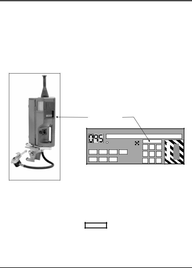
1.7CDU MAJOR COMPONENTS
The photo and illustration below shows the CDU Model 6696 external components and typical front panel layout.
|
|
Union Switch & Signal Inc. |
|
|
|
|
|
|
|
|
|
ID = 85323 |
|
||
PRESSURE |
|
|
|
|
|
E |
|
|
|
COMM |
|
MENU |
M |
||
|
|
|
|
||||
|
|
|
|
ARM |
UP |
E |
|
MARKER |
|
R TO F |
|
|
|
|
R |
MOVING |
ALARM |
|
|
|
G |
||
ON |
FAILURE |
|
|
|
E |
||
|
|
|
SET |
||||
|
|
|
|
N |
|||
|
|
|
|
|
|
|
|
LOW |
|
F TO R |
|
|
|
|
C |
STOPPED |
|
|
|
MENU |
Y |
||
BATTERY |
FAILURE |
|
CANCEL |
|
|
||
|
|
DOWN |
|
||||
|
|
|
|
|
|||
Figure 1-1. - Model 6696 CDU Features & Front Panel Layout
1.7.1CDU Unit Housing
The CDU Model 6696 uses the same exterior aluminum alloy housing used on previous versions of DIGITAIR Cab Units. This helps ensure the Model 6696 will fit into, and be compatible with, existing locomotive installations. Two mounting configurations are available; a Standard Mounting Tray style mount, and an AAR Clean Cab Enclosure style mount.
The CDU is designed to be lightweight (9 pounds) and incorporates a fold-out carrying handle for transporting the unit to the locomotive or between locomotives.
SM 7063 07/97 |
1-6 |

SECTION I INTRODUCTION
1.7.2CDU Rear Panel
The photo below shows a typical rear panel connector layout for the CDU Model 6696.
Figure 1-2. Model 6696 CDU Features (Rear Panel View)
The CDU supports connectors on its rear panel for the following functions:
Power: 72 VDC nominal locomotive power or 13.6 VDC nominal for mobile use.
Axle Alt.: Connects to locomotive’s axle alternator for Odometer related functions.
Antenna: Connects to roof mounted locomotive UHF antenna.
Datalogger: Can be interfaced to an event recorder, computer, or serial printer.
Diag: Connects to a PC serial port for diagnostic and configuration purposes.
Mounting hardware on the rear panel includes:
|
Screw Latch: |
Spring loaded latch secures the CDU to the Mounting Tray or AAR Clean Cab |
|
|
Enclosure. |
|
Lock Bracket: |
Provides a means for locking the CDU to the Mounting Tray using a padlock. |
SM 7063 07/97 |
1-7 |

SECTION I INTRODUCTION
1.7.3CDU Major Assemblies
The photo below shows a top view of the CDU with its cover removed exposing the major assemblies. The unit has been designed using a modular approach for ease of production and user maintenance.
Figure 1-3. Model 6696 CDU Features (Top Internal View)
The CDU is comprised of the following three (3) major sub-assemblies:
Front Panel Assembly: Contains the Processor Board, LED Display Driver Board, Display Panel, and Emergency Switch Assembly.
Rear Panel Assembly: Contains the Interface Connectors and UHF Transceiver Module.
Base Assembly: Contains the Bottom Housing, Power Supply Circuitry, and serves as the
base into which the Front and Rear Panel Assembly plug.
SM 7063 07/97 |
1-8 |

SECTION I INTRODUCTION
1.8CDU FUNCTIONAL BLOCK DIAGRAM
The following is a functional block diagram of the CDU Model 6696 showing its major sub-systems and external interfaces.
Key XMTR |
|
|
Lap-top |
|
||
|
|
for Diagnostics |
||||
Transceiver |
Sleep |
Internal |
Diagnostics and Calibration |
|||
|
|
|||||
|
UART |
Information |
|
|
||
Carrier Detect |
|
|
|
|||
|
|
|
|
|||
Transmit |
|
CPU |
|
|
|
|
Audio |
|
|
|
|
|
|
MODEM |
|
|
|
|
|
|
Receive |
|
|
|
|
|
|
Audio |
|
|
|
|
|
|
|
|
|
DUAL |
Datalogger or |
||
|
|
|
CHANNEL |
Event Recorder Device |
||
|
|
|
UART |
|
|
|
|
12 |
|
|
|
|
|
General Digital Inputs |
2 |
|
|
|
|
|
Front Panel Switches |
10 |
FLASH |
System |
|
|
|
RAM |
RAM |
|
|
|||
|
|
|
|
|||
Reverser Switch Inputs |
2 |
|
|
|
|
|
20/60 PPR Axle Alter. Select |
1 |
|
|
|
|
|
Axle Alternator Input |
1 |
|
|
Front Panel Displays |
||
|
|
Parameter |
Boot |
Power Supply |
||
|
|
EEPROM |
EPROM |
|||
|
|
|
|
|||
|
Cab Unit Block Diagram |
or |
or |
|||
4/3/96 |
|
|
|
+12VDC |
+74VDC |
|
|
|
|
|
|||
Figure 1-4. CDU Model 6696 Functional Block Diagram
SM 7063 07/97 |
1-9 |

SECTION I INTRODUCTION
SM 7063 07/97 |
1-10 |

SECTION II INSTALLATION
2.0INSTALLATION OF THE CDU
This section details the installation of a CDU into the locomotive cab environment. Two versions of CDU mounting arrangements are available:
1.CDU mounted on a Mounting Tray.
2.CDU mounted in an AAR Clean Cab Enclosure.
2.1General Description
The locomotive equipment comprises a Model 6696 Communication Display Unit (CDU). Available accessories include (refer to Table 1.1 for part numbers):
Complete Installation Kits
Mounting Tray
Antenna Cable Kit
UHF Antenna
Power Cable Assemblies
Odometer Cable Assemblies
Diagnostic Software Disk
The Power and Odometer cables may be purchased separately or fabricated by the Railroad.
The locomotive antenna and antenna cable may be purchased from US&S or supplied by the Railroad. The cable must employ a PL-259 style UHF connector. The antenna itself must be 1/4 wave whip or a low profile slot-type antenna.
If desired, the Railroad may supply a padlock to lock the CDU into position on the Mounting Tray.
2.2Preparing the Locomotive
This section provides information on preparing a locomotive for installation of the CDU. Once the locomotive has been equipped as described in this section, the CDU may be installed as instructed in 2.4.
Preparing the locomotive involves equipping it with either a Mounting Tray or AAR Clean Cab Enclosure and wiring the required electrical connections. Note that some locomotives may already have this equipment installed.
2.2.1Mounting Tray Installation
The Mounting Tray is typically located on the control stand and provides the CDU with a mechanical quickdisconnect base for easy application and removal. The Mounting Tray is affixed to the control stand as follows:
1.Using a Mounting Tray as a template, mark the control stand for drilling.
2.Drill holes of 1/4" diameter.
3.Attach the Mounting Tray to the control stand using appropriate bolts, nuts, and lockwashers (supplied by the Railway).
SM 7063 07/97 |
2-1 |

SECTION II INSTALLATION
2.2.2AAR Clean Cab Enclosure
Installation of an industry standard AAR Clean Cab Enclosure in the locomotive is the responsibility of the Railway.
2.3Installing the CDU Cables
This section details the installation of the Power and Odometer cables required to connect the CDU to the locomotive. The cables and their respective part numbers are listed in Table 1-1 in the previous section.
2.3.1Power Cable Installation
For most installations, one of two types of power cable assemblies are used to connect the CDU to the locomotive DC power system. One is a 5-pin Bayonet Twist Lock type (CA) connector and the other is a 4- pin MS Threaded type connector. In both cases, the cable assemblies are supplied with the connector pre-mounted on one end of the cable, with the other end left unterminated.
CAUTION
Non-standard cables, or those supplied by the Railroad, may employ different color codes than those used by US&S. Refer to the connector pin assignments in this manual or consult US&S Customer Service at 1-800-652-7276 for further technical assistance, if required.
Cut the cable to the desired length. Strip and install whatever spade lug, tab, or other contact is required for the locomotive. The three conductor cable should be wired per the table below:
Pin |
Conductor |
Bayonet (CA) Type Connector |
MS Threaded Type Connector |
|
|
|
|
A |
Black |
+ 72 VDC Locomotive Power |
+ 72 VDC Locomotive Power |
B |
N.C. |
+ 13.6 VDC Mobile Power |
13.6 VDC Mobile Power Ground |
C |
White |
72 VDC Locomotive Power Return |
72 VDC Locomotive Power Return |
D |
N.C. |
13.6 VDC Mobile Power Ground |
+ 13.6 VDC Mobile Power |
E |
Green |
Chassis |
Not Used |
|
|
|
|
Note: N.C. = Not Connected
Table 2-1. CDU Power Connections
2.3.2Odometer (Axle Alternator) Cable Installation
Two standard Odometer Cables are available. Each consists of a dual twisted pair, individually shielded cable with either a 6-pin Bayonet Twist Lock type (CA) connector or 6-pin MS Threaded type connector on one end. The other end is unterminated.
CAUTION
Non-standard cables, or those supplied by the Railroad, may employ different color codes than those used by US&S. Refer to the connector pin assignments in this manual or consult US&S Customer Service at 1-800-652-7276 for further technical assistance, if required.
SM 7063 07/97 |
2-2 |

SECTION II INSTALLATION
Cut the odometer cable to the desired length. Strip and install whatever spade lug, tab, or other contact is required for the locomotive. The shield wire(s) connects to the CDU chassis at the connector end; cut the shield wire(s) at the locomotive end and leave unconnected. The cables should be wired per the tables below.
For the Bayonet Twist Lock type (CA) connector, the pin assignments and cable color codes are:
Pin |
Conductor |
Bayonet Twist Lock Type (CA) Connector |
|
A |
RED-1 |
Axle Alternator Signal Input |
|
B |
RED-2 |
Direction A (TL8) |
|
C |
BLK-2 |
Direction B (TL9) |
|
D |
See notes * |
20 |
/ 60 PPR Return |
E |
See notes * |
20 |
/ 60 PPR Select |
F |
BLK-1 |
Axle Alternator Signal Return |
|
|
|
|
|
Table 2-2. CDU Axle Alternator Connections (Bayonet Twist Lock Type Connector)
*Notes:
PPR = Pulses Per Locomotive Wheel Revolution
For 20 PPR operation, retain jumper between pins D and E.
For 60 PPR operation, cut jumper between pins D and E.
For the MS Threaded type connector, the pin assignments and cable color codes are:
Pin |
Conductor |
MS Threaded Type Connector |
|
A |
RED-1 |
Axle Alternator Signal Input |
|
B |
BLK-1 |
Axle Alternator Signal Return |
|
C |
See notes * |
20 |
/ 60 PPR Select |
D |
See notes * |
20 |
/ 60 PPR Return |
E |
RED-2 |
Direction A (TL8) |
|
F |
BLK-2 |
Direction B (TL9) |
|
|
|
|
|
Table 2-3. CDU Axle Alternator Connections (MS Threaded Type Connector)
*Notes:
PPR = Pulses Per Locomotive Wheel Revolution
For 20 PPR operation, retain jumper between pins C and D.
For 60 PPR operation, cut jumper between pins C and D.
NOTE
When routing the odometer cable from the axle alternator to the CDU, ensure that it is kept clear of locomotive "dirty" (noisy) wiring.
SM 7063 07/97 |
2-3 |

SECTION II INSTALLATION
2.3.3Antenna and Cable Installation
Install the UHF antenna at least 6" from the edge of the locomotive roof and at least 12" from any other fixture on the roof. Try to keep the cable run as short as possible.
If interference from a nearby transmitting antenna (e.g. voice radio) is likely to be a problem, locate the antenna as far away as possible.
Affix the antenna cable in place and terminate it in a PL-259 UHF connector. Use only a high quality low loss antenna cable such as RG-213/U.
2.3.4CDU Datalogger Connector
All CDUs are equipped with a DATALOGGER port connector. This is a 25-pin serial RS-232/C “D” type connector mounted on the rear panel. Four of the 25 pins are used as listed in the table below:
Pin |
DATALOGGER Connector |
1 |
Chassis Ground (Shield) |
2 |
Receive Data (RX DATA) |
3 |
Transmit Data (TX DATA) |
7 |
Signal Ground |
|
|
Table 2-4. CDU DATALOGGER Port Connections
The connector is designed to operate as a DCE type serial port where pin 2 is used to receive data from a remote serial device and pin 3 is used to transmit data to a remote serial device. This allows for the use of a “straight-through” (not a null modem) type serial cable.
Note that Chassis Ground and Signal Ground are isolated from each other. The serial communications parameters (baud rate, etc.) are configurable via a Diagnostic PC as described in Section IV of this manual.
2.3.5Event Recorder Connector
For CDUs equipped with a circular Event Recorder connector, the connector pin assignments are as follows:
Pin |
|
Event Recorder Connector |
A |
|
Receive Data (RX DATA) |
B |
|
Transmit Data (TX DATA) |
C |
|
Signal Common |
D |
|
Chassis (SHIELD) |
E |
|
Spare 1 |
F |
|
Spare 2 |
|
|
|
|
Table 2-5. CDU Event Recorder Connections |
|
SM 7063 07/97 |
2-4 |
SECTION II INSTALLATION
2.4MOUNTING THE CDU
This section details mounting the CDU onto the Mounting Tray or in the AAR Clean Cab Enclosure.
2.4.172 VDC / 12 VDC Power Selection Jumper (JP1)
The CDU can be powered from either the standard 72 VDC locomotive power system or a 13.6 VDC (nominal) power source such as an automobile lighter socket. An internal Power Selection Jumper (JP1) located on the Base Assembly allows the user to select one power source or the other.
The CDU is shipped with this jumper set to the 72V position.
To change the Power Selection Jumper setting, simply remove the CDU’s top cover, remove the jumper plug, and place it in the desired position as marked on the PCB silk-screen. Replace the top cover.
2.4.2Installing the CDU onto a Mounting Tray
CAUTION
Prior to connecting any cables to the CDU, it is recommended that the locomotive Radio Circuit Breaker be turned OFF.
a)Slide the CDU into the keyhole slots in the Mounting Tray.
b)Engage the screw latch at the rear of the CDU.
c)Tighten the screw latch until the CDU is firmly in place. Do not overtighten. Padlock the unit, if desired.
d)Connect the CDU Power cable to the power connector on the CDU.
e)If applicable, connect the CDU Odometer cable to the Axle Alt connector on the CDU.
f)If applicable, connect the CDU Datalogger/Event Recorder cable to the Datalogger/Event Recorder connector on the CDU.
g)Connect the Antenna cable to the mating RF connector on the CDU.
2.4.3Installing the CDU into an AAR Clean Cab Enclosure
a)Slide the CDU into the enclosure from the back.
b)Engage the screw latch at the rear of the CDU.
c)Tighten the screw latch until the CDU is firmly in place. Do not overtighten.
d)Connect the CDU Power cable to the power connector on the CDU.
e)If applicable, connect the CDU Odometer cable to the Axle Alt connector on the CDU.
f)If applicable, connect the CDU Datalogger/Event Recorder cable to the Datalogger/Event Recorder connector on the CDU.
g)Connect the Antenna cable to the mating RF connector on the CDU.
SM 7063 07/97 |
2-5 |

SECTION II INSTALLATION
2.5BRIEF OPERATIONAL TEST OF THE CDU
Upon receipt of a new CDU, it is recommended that the unit be briefly tested as described in this section to verify correct operation. This is performed in conjunction with a known operational End Unit.
2.5.1CDU Power-Up Sequence
Upon CDU power-up, verify that the following display sequence is indicated on the CDU’s Front Panel:
The 32-Character LED Display (Function Menu Display) shows “Self Test in progress” accompanied by a beep tone. All other displays should be off.
The Brake Pressure Display shows three dashes “- - -” .
The 8-character LED Display (ID Code Display) shows the currently stored End Unit ID code (e.g.,
“ID=85323” ).
The Function Menu Display continues showing the following message sequence:
“Union Switch & Signal Inc.” (by default) or a customer specified character string.
“Version: Revision X” .
“Boot PROM Version: REV X” .
“RAM test: passed” .
“ROM test: passed” .
“EEPROM test: passed” .
“USC test: passed” .
“Boot ROM test: passed” .
“Self Test Complete: passed” .
After completion of the above test sequence, the CDU reverts to its top (first ) function menu item where the Function Menu Display shows (with the example ID code):
“Change ID: 85323 “
with the first digit flashing, ready for input by the operator.
If a power-up diagnostic test fails, this will be indicated as such, and the power-up sequence will halt. Note the specific test that has failed and contact US&S Customer Service at 1-800-652-7276 for technical assistance or warranty repair instructions.
SM 7063 07/97 |
2-6 |

SECTION II INSTALLATION
2.5.2CDU Functional Check
Perform the following basic steps to verify that the CDU is functioning correctly:
Obtain a known operational End Unit. It may be operated within the locomotive without damage and no pressurized air is necessary.
Power-up the CDU, observe it completes its power-on sequence, and then enter the ID code of the End Unit into the CDU.
NOTE
If the CDU is configured to support the “Arming” security feature, it w ill prompt the user to perform the Arming process as described in Section III. IT IS NOT NECESSARY TO DO THIS IN ORDER TO PERFORM A FUNCTIONAL CHECK OF THE CDU.
Press the external TEST button to activate the End Unit and cause it to transmit a message. Observe the Brake Pressure Display on the CDU. With no air pressure applied to the End Unit, the pressure reading should change from “- - -” to “ 0” psi. This will be accompanied by a Low Pressure Alarm since the pressure is below the standard 45 psig threshold and is normal.
Press the COMM ARM key on the CDU to initiate an RF link check. Observe the CDU’s 32-character LED Display briefly shows “WAITING FOR REPLY” , shortly followed by “COMM TEST OK” . This confirms correct operation of the CDU’s RF transceiver and associated control circuits.
Note: The rightmost decimal point in the Brake Pressure Display serves as an indicator to show that a message has been received from the End Unit. It will briefly light each time a message is received.
Verify the integrity of the Emergency Switch contacts by activating the switch and observing a “SYSTEM IS NOT ARMED” message on the Function Menu Display.
Perform a LAMP TEST to verify that all of the LED display segments light. This is done by simultaneously pressing the MENU UP and MENU DOWN keys as marked on the front panel .
Observe that each of the CDU’s nine (9) Control Pushbuttons are illuminated (i.e., backlit).
SM 7063 07/97 |
2-7 |

SECTION II INSTALLATION
SM 7063 07/97 |
2-8 |
SECTION III OPERATION
3.0CDU OPERATING INSTRUCTIONS
This section provides detailed information on the CDU’s various operating modes and functions, and how each one is used.
3.1Purpose and Use of ID Code
Each End Unit has a unique 5-digit numeric Identification Code (ID Code) assigned by the AAR “Central Train Information System Clearinghouse”. The ID Code is programmed into each End Unit and is a part of every message it transmits. This code is permanently marked on a label or plate mounted on the outside of the End Unit. The ID code entered into the CDU must match the End Unit ID code before EOT messages can be received and displayed. Likewise, the End Unit will only accept and process commands from a CDU with the matching ID code.
ID Code Must Match
Union Switch & Signal Inc.
|
|
ARMED |
ID = 85323 |
|
||
PRESSURE |
|
|
|
E |
||
|
|
|
|
|||
|
COMM |
|
MENU |
M |
||
|
|
|
||||
|
|
|
ARM |
UP |
E |
|
MARKER |
|
R TO F |
|
|
|
R |
MOVING |
ALARM |
|
|
G |
||
ON |
FAILURE |
|
|
E |
||
|
|
SET |
||||
|
|
|
N |
|||
|
|
|
|
|
|
|
|
|
F TO R |
|
|
|
C |
LOW |
STOPPED |
|
|
MENU |
Y |
|
BATTERY |
FAILURE |
CANCEL |
|
|
||
|
DOWN |
|
||||
|
|
|
|
|||
Cab Unit (CDU Model 6696)
Typical End Unit
3.2Radio Communication Channel
Since all End Units transmit on the same radio channel frequency (typically 457.9375 MHz), the ID code is the only way the CDU can distinguish one End Unit from another. In a similar fashion, all CDUs transmit on the same radio channel frequency (typically 452.9375 MHz) and the End Unit relies on the ID code to distinguish between commands sent by the CDU.
CAUTION
Ensure the ID code entered into the CDU matches that of the End Unit installed on the respective train before actuating the EMERGENCY switch.
With the correct ID code entered, the CDU is ready to begin receiving messages for display.
SM 7063 07/97 |
3-1 |
 Loading...