

INDUSTRIAL SEWING EQUIPMENT
INSTRUCTIONS, ENGINEER’S AND ILLUSTRATED PARTS MANUAL
INSTRUCCIONES, MANUAL DEL INGENIERO Y
LISTADO ILUSTRADO DE PARTES
Bag Feed-in Devices
Alimentador de Sacos
29900
MANUAL NO. / CATALOGO Nº 270B
FOR STYLES / PARA ESTILOS
G29905 / GR29905 / GB29905 / GBR29905
G29910 / GR29910 / GB29910 / GBR29910
GB29915 / GBR29915
GBR29920

MANUAL NO. 270B
INSTRUCTIONS FOR BAG FEED-IN DEVICES 29900
Fifth Edition Copyright 2003
by
Union Special GmbH Rights Reserved in all
Countries
Printed in Germany
PREFACE
This manual has been prepared to guide you while operating bag feed-in devices 29900.
This manual explains in detail the proper settings for operation of the bag feed-in device. Illustrations are used to show
the adjustments and reference letters are used to point out
specific items discussed.
Careful attention to the instructions and cautions for operating and adjusting these bag feed-in devices will enable you
to maintain the superior performance and reliability designed and built into every Union Special bag feed-in device.
Adjustments and cautions are presented in sequence so
that a logical progression is accomplished. Some adjustments performed out of sequence may have an adverse
effect on the function of the other related parts.
This manual has been comprised on the basis of available
information. Changes in design and / or improvements may
incorporate a slight modification of configuration in illustrations or cautions.
On the following pages will be found illustrations and terminology used in describing the instructions for your bag feedin device.
CATALOGO Nº. 270B
INSTRUCCIONES PARA EL ALIMENTADOR
DE SACOS MODELO 29900
Quinta Edición © 2003
Por Union Special GmbH - Derechos reservados
en todos los paises
Impreso en Alemania
INTRODUCCION
Este manual fue preparado para guiar al usuario en la
operación del alimentador de sacos modelo 29900.
Este manual explica detalladamente los ajustes para la
operación del equipo. Las ilustraciones sirven para demostrar los ajustes y las letras en referencia indican los puntos
específicos discutidos.
Una cuidadosa atención a las instrucciones y las precauciones operando y ajustando este equipo le va a permitir
mantener el mejor funcionamiento y la confiabilidad que
caracteriza los alimentadores de sacos de Union Special.
Los ajustes y precauciones son presentados en secuencia
para que se consiga una progresión lógica. La ejecución
de algunos ajustes fuera de la secuencia puede causar un
efecto adverso para el funcionamiento de otras partes relacionadas.
Este manual se comprende a base de la información actual. Cambios en diseño y/o mejoras pueden significar leves modificaciones de la configuración de las ilustraciones
o precauciones.
En las paginas siguientes se encuentran ilustraciones y
terminologías usadas en la descripción de las instrucciones y las piezas del alimentador de sacos.
I

TABLE OF CONTENTS
INDICE
Preface Introducción I
Safety Rules Reglas de seguridad 2-3
Styles of Machines Estilos de máquinas 3
Types of Bag Closures Tipos de cerrado de sacos 4
Maintenance Mantenimiento 5
Assembling Montaje 5
Page / Página
Synchronizing the Feed-in Speed
with the Conveyor Speed
Tightening and Adjusting the
Chains
Adjusting the Chain Pressure Ajuste de la presión de la cadena 8-9
Adjusting the Bag-Top Fold-over
Device
Adjusting the Knives and Tape Folder of Bag
Feed-in Device Nos. G29910, GR29910,
GB29910, GBR29910 and GBR29920
Adjusting the Knives of Bag Feed-in Device
Nos. GB29915 and GBR29915
Pre-Feeler Switch Interruptor del pre palpador 11
Assembly of Chain Guide and Sprocket Gears Montaje de la cadena guía y los
Blower Device Soplador 12
Sincornización de la velocidad del
alimentador con la velocidad de la
cadena de alimentación
Apretado y ajuste de las cadenas 8
Ajuste del dobladillador superior 9
Ajuste de las cuchillas y el rollo de cinta del
alimentador, modelos G29910, GR29910,
GB29910, GBR29910 y GBR29920
Ajuste de las cuchillas del alimentador, modelos
GB29915 y GBR29915
piñones del engranaje
6-7
9-10
10-11
12
Ordering Wear and Spare Parts Pedido de partes y piezas 12
Views and Description of Parts Vistas y descripción de las partes y piezas 13-35
Numerical Index of Parts Indice numérico de partes y piezas 36-38
Manufacturer’s Declaration Certificación del fabricante II
1

SAFETY RULES REGLAS DE SEGURIDAD
1. Before putting the bag feed-in devices described in this
manual into service, carefully read the instructions. The
starting of each machine is only permitted after taking
notice of the instructions and by qualified operators.
IMPORTANT! Before putting the machine into service,
also read the safety rules and instructions from the motor
supplier.
2. Observe the national safety rules valid for your country.
3. The machines described in this instruction manual are
prohibited from being put into service until it has been ascertained that the sewing units which these machines will
be built into, have conformed with the provisions of EC
Machinery Directive 98/37/EC, Annex II B.
Each machine is only allowed to be used as foreseen.
The foreseen use of the particular machine is described in
paragraph “STYLES OF MACHINE” of this instruction manual. Another use, going beyond the description, is not as
foreseen.
4. All safety devices must be in position when the machine
is ready for work or in operation. Operation of the machine without the appertaining safety devices is prohibited.
5. Wear safety glasses.
6. In case of machine conversions and changes all valid
safety rules must be considered. Conversions and changes are made at your own risk.
7. The warning hints in the instructions are marked with one
of these two symbols:
8. When doing the following the sewing unit has to be dis-
connected from the power supply by turning off the main
switch or by pulling out the main plug:
8.1 When threading needle(s), looper etc.
8.2 When replacing any parts such as needle(s), presser
foot, throat plate, looper, feed dog, needle guard,
folder, fabric guide etc.
8.3 When leaving the workplace and when the workplace
is unattended.
8.4 When doing maintenance work.
1. Antes de poner en marcha el alimentador de sacos descrito en te manual, hay que leer cuidadosamente las instrucciones. El arranque de cada máquina solamente se
permite después de haber leído las instrucciones y por
personal calificado.
IMPORTANTE! Antes de poner la máquina a operar,
también hay que leer las reglas de seguridad y las instrucciones del fabricante del motor.
2. Observe las reglas nacionales de seguridad que rigen
para su país.
3. No se puede poner en marcha la máquina descrita en
este manual hasta que se confirme que la unidad de coser esta conforme con el reglamento del Directivo de
las Máquinas de la Comunidad Europea 98/37/EC,
Anexo II B.
La máquina solamente se puede utilizar para su uso
previsto. El uso previsto está descrito en el capitulo ESTILOS DE MAQUINAS de este manual de instrucciones.
Otro uso, diferente de la descripción, no está previsto.
4. Todos los dispositivos de seguridad tienen que estar en
su sitio cuando la máquina esté lista para trabajar u
operando. La operación de la máquina sin los dispositivos de seguridad esta prohibida.
5. Utilice lentes de seguridad.
6. En el caso de una modificación de la máquina hay que
tomar en cuenta las reglas de seguridad. Modificaciones
y cambios corren por su riesgo.
7. Las advertencias en el manual de instrucciones están
marcadas con las siguientes señales de aviso:
8. Para las siguientes maniobras hay que desconectar la
máquina del suministro eléctrico desconectando el enchufe principal:
8.1. Enhebrando agujas, loopers y spreaders.
8.2. Reemplazando piezas como agujas, pie prensa telas, plancha de aguja, loopers, dientes de
arrastre, guarda agujas, dobladilladores,
guía telas, cuchillas, etc.
8.3. Cuando salga de su puesto de trabajo y no se
encuentre alguien para atender la máquina.
8.4. Durante trabajos de mantenimiento.
2

9. Maintenance, repair and conversion work (see item 8)
must be done only by trained technicians or specially skilled personnel under consideration of the instructions.
Only genuine spare parts approved by UNION SPECIAL
have to be used for repair. These parts are designed
specifically for your machine and manufactured with utmost precision to assure long lasting service.
10. Any work on the electrical equipment must be done by an
electrician or under direction and supervision of specially
skilled personnel.
11. Work on parts and equipment under electrical power is
not permitted. Permissible exceptions are described in
the applicable section of standard sheet EN 50110 / VDE
0105.
12. Before doing maintenance and repair work on the pneu-
matic equipment, the machine has to be disconnected
from the compressed air supply. In case of existing residual air pressure after disconnecting from compressed
air supply (i.e. pneumatic equipment with air tank), the
pressure has to be removed by bleeding.
9. Mantenimiento, reparaciones y trabajos de conversión
(véase No. 8) solamente pueden ser efectuados por técnicos entrenados o personal especializado bajo consideración de las instrucciones.
Solamente repuestos originales y aprobados por UNION
SPECIAL pueden ser utilizados para reparaciones. Estos
repuestos han sido diseñados específicamente para estas máquinas, con precisión y para asegurar su máxima
vida útil
10. Cualquier trabajo con equipo eléctrico tiene que ser ejecu-
tado por un electricista o bajo la supervisión de personal
especialmente entrenado.
11. No está permitido trabajar en piezas y equipos con la
electricidad conectada. Excepciones permitidas están
descritas en EN 50110 / VDE 0105.
12. Antes de hacer mantenimiento o reparaciones del equipo
neumático, hay que desconectar la máquina de la alimentación del aire comprimido. En el caso que exista
una presión de aire residual después de desconectar la
máquina (por ejemplo equipos con tanques de aire), la
presión tiene que ser eliminada abriendo las válvulas.
STYLES OF MACHINES
BAG FEED-IN DEVICES
for feeding bags and sacks into bag closing machines.
Special conveying chains to protect the bag material.
Standard voltage for motors: 220-240, 380-415 V,
3 phase, 50 Hz / 243-277, 420-480 V, 3 phase, 60 Hz.
Degree of protection: IP 55. Insulation class F.
Painting: RAL 9002, powder coated.
Delivery includes pre-feeler switch 29926A to start the
sewing machine.
Other voltages and frequencies on request.
ESTILOS DE MAQUINAS
ALIMENTADOR DE SACOS
Para alimentar sacos en máquinas cerradoras de sacos.
Cadenas continuas especialmente diseñadas para proteger
el material del saco.
Voltaje estándar del motor: 220-240, 380-415 V,
trifásico, 50 Hz / 243-277, 420-480 V, trifásico, 60 Hz.
Grado de protección: IP 55. Insolación clase F.
Pintura: RAL 9002, cubierta pulverizada.
Envío incluye interruptor del pre palpador 29926A para
arranque de la máquina de coser.
Otras frecuencias y voltajes disponibles contra pedido.
3
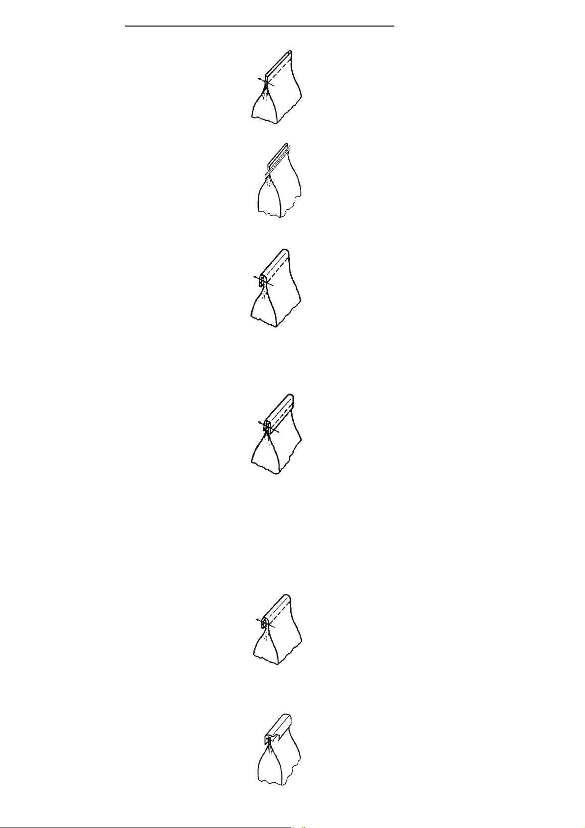
TYPES OF BAG CLOSURES / TIPOS DE CERRADO DE SACOS
GB29905G Bag feed-in device
The spread paper, HDPE-foil or woven PP bag is
fed into the sewing machine.
Speed 11-23 m/min. at 50 Hz. Gear motor I =
30:1.Depending on the length and filling height of
the bag the seam can be adjusted to a depth of up
to 120 mm from the top of the bag, standard setting
30-40 mm. Suitable for sewing machines of styles
BC111P12-1M, -1A, -1B.
BC191PT12-1M, -1A, -1B.
G29905G, same as GB29905G, but short version.
GBR29905G, same as GB29905G, but speed 9-16
m/min. at 50 Hz.
Gear motor I = 38:1.
Suitable for sewing machines of styles
BC111P12 -1M, -1A, -1B, 80800R, RL, RLM.
BC191PT12-1M, -1A, -1B.
GR29905G, same as GBR29905G, but short version.
93051FA, Bag-top fold-over device to fold the bag
top to the rear. Assembling to the bag feed-in devices GB29905G and GBR29905G required.
For all kinds of self-supporting bags.
Performance test of bag material recommended.
GB29910G Combined bag feed-in, trimming and
taping device with crepe tape folder. Width of tape
not adjustable. Folder available for 50, 55 and 60
mm wide tapes. Please specify. Standard 50 mm.
Speed 11-23 m/min. at 50 Hz. Gear motor I = 30:1.
The paper or HDPE-foil bag top is trimmed approx.
20 mm (max. 90 mm). Taped before sewing. Performance test of bag material recommended.
Suitable for sewing machines of style
BC111TA12-1M.
G29910G, same as GB29910G, but short version.
Suitable for sewing machines of style
BC111TA12-1M.
GBR29910G, same as GB29910G, but speed 9-16
m/min. at 50 Hz. Gear motor I = 38:1
Suitable for sewing machines of styles
BC111TA12-1M, 80800UA, UAL, UALM.
GR29910G, same as GBR29910G, but short version.
GB29915G, Combined bag feed-in, trimming and
fold-over device. Speed 11-23 m/min. at 50 Hz.
Gear motor I = 30:1,
Performance test of bag material recommended.
The paper or HDPE-foil bag top is trimmed approx.
20 mm (max. 50 mm), folded over to the rear by
approx. 30-40 mm and fed into the sewing machine.
Suitable for sewing machines of styles
BC111P12-1M, -1A, -1B.
GBR29915G, same as GB29915G, but speed 9-16
m/min. at 50 Hz. Gear motor I = 38:1.
Suitable for sewing machines of styles
BC111P12-1M, -1A, -1B, 80800R, RL, RLM.
GBR29920G, Combined bag feed-in and trimming
device. Speed 9-16 m/min. at 50 Hz.
Gear Motor I = 38:1. The paper or HDPE-foil bag top
is trimmed approx. 20 mm (max. 90 mm).
Taped after sewing.
Performance test of bag material recommended.
Suitable for sewing machine of styles
BC111KA12-1M, 80800TAL.
GB29905G Alimentador de sacos
El saco de papel, folios de HDPE o polipropileno tejido
es introducido en la máquina de coser.
Velocidad de 11-23 m/min. para 50 Hz. Piñón del motor
I = 30:1. Dependiendo del largo y el peso del saco lleno,
la costura puede ser ajustada a una profundidad de
hasta 120 mm, con un ajuste estándar de 30 - 40 mm.
Adecuado para las máquinas estilos BC111P12-1M, 1A, -1B, BC191PT12-1M, -1A, -1B.
G29905G, igual a la GB29905G, pero en versión corta.
GBR29905G, igual a la GB29905G, pero con una velo-
cidad de 9-16 m/min. a 50 Hz.
Piñón del motor I = 38:1.
Adecuado para las máquinas estilos
BC111P12-1M, -1A, -1B, 80800R, RL, RLM.
BC191PT12-1M, -1A, -1B.
GR29905G, igual a la GBR29905G, pero en versión
corta.
93051FA, Con aditamento para doblar la parte superior
del saco hacia atrás. Solo funciona en conjunto con el
alimentador de sacos modelos GB29905G y
GBR29905G.
Para todo tipo de sacos que se puedan mantener parados sobre si mismos. Se recomienda realizar un test del
material a usar.
GB29910G Alimentador de sacos, cortador y pegador
de cintas combinado con un dobladillador. El ancho de
la cinta no se puede ajustar, ya que el dobladillador solo
está disponible para cintas de 50, 55 y 60 mm. Favor
especificar el ancho. estándar 50 mm. Velocidad: 11-23
m/min. a 50 Hz. Piñón del motor I = 30:1. El saco es
cortado aproximadamente a 20 mm (máx. a 90 mm). La
cinta es montada antes de pasar la costura. Se recomienda realizar un test del material. Adecuado para las
máquinas estilo BC111TA12-1M.
G29910G, igual a la GB29910G, pero en versión corta.
Adecuado para las máquinas estilo BC111TA12-1M.
GBR29910G, igual a la GB29910G, pero con velocidad
de 9-16 m/min. a 50 Hz. Piñón del motor I = 38:1.
Adecuado para las máquinas estilos BC111TA12-1M,
80800UA, UAL, UALM.
GR29910G, igual a la GBR29910G, pero en versión
corta.
GB29915G, Alimentador de sacos, cortador y dobladillador superior combinado. Velocidad 11-23 m/min. a 50
Hz. Piñón del motor I = 30:1.
Se recomienda realizar un test del material. El saco es
cortado aproximadamente a 20 mm (máx. a 50 mm),
doblado hacia atrás aproximadamente 30-40 mm y alimentado dentro del saco.
Adecuado para las máquinas estilos
BC111P12-1M, -1A, -1B.
GBR29915G, igual a la GB29915G, pero con una velocidad de 9-16 m/min. a 50 Hz.
Piñón del motor I = 38:1.
Adecuado para las máquinas estilos
BC111P12-1M, -1A, -1B, 80800R, RL, RLM.
GBR29920G, Alimentador de sacos y cortador de cintas
combinado. Velocidad de 9-16 m/min. a 50 Hz.
Piñón del motor I = 38:1. El saco es cortado aproximadamente a 20 mm (máx. a 90 mm). La cinta es montada
antes de pasar la costura.
Se recomienda realizar un test del material.
Adecuado para las máquinas estilos
BC111KA12-1M, 80800TAL.
4
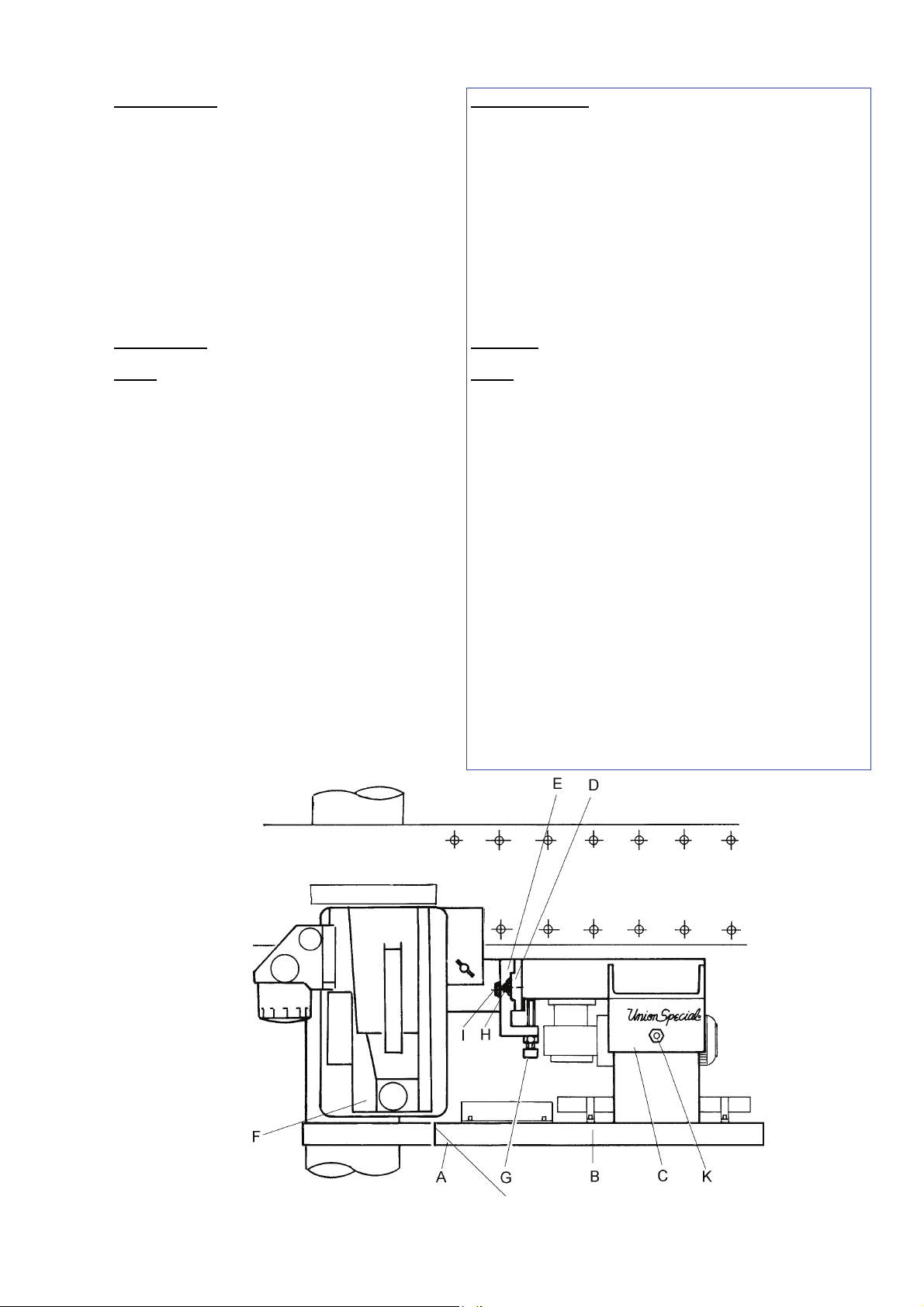
MAINTENANCE
When sacking flour, salt, aggressive fertilizers, chemicals, etc. the feeding chains of the bag feed-in device
have to be cleaned and lubricated daily to prevent corrosion.
To clean and lubricate the feeding chains remove the
lower cover plates (A, Fig. 1) which are fixed with 4
screws each at the carrier plates (B, Fig. 1).
The gears are lubricated once per month through the
grease nipple (A. Fig. 2). We recommend BPEnergrease or equivalent.
ASSEMBLING
Instructions stating direction or location, such
NOTE:
as right, left, front or rear of bag feed-in device, are
given relative to operator’s position at the bag closing
unit, unless otherwise noted.
Mount the bag feed-in device (C, Fig. 1) with the
bracket (D, Fig. 1) to the traverse (E, Fig. 1) on column. The carrier plates (B, Fig. 1) should be as close
as possible below the sewing machine (F, Fig. 1) without contacting it. Fix this height setting between bag
feed-in device and bracket with supporting screw (G,
Fig. 1). Tighten the two screws (H, Fig. 1). Align the
bag feed-in device horizontally with the bracket relative to the sewing machine. Rear chain should match
the throat plate surface of the sewing machine, but
when using GB29915, GBR29915 or 93051FA rear
chain should be positioned in front of the throat plate
surface depending on the thickness of the bag.
Tighten the two screws (I, Fig. 1) and recheck the
height setting position of the bag feed-in device.
Connect the plug of the bag feed-in device to the corresponding socket on column switch box.
MANTENIMIENTO
Cuando se ensaque harina, sal, fertilizantes, quimicos, etc., las
cintas transportadoras del alimentador de sacos deben ser
limpiadas y lubricadas diariamente para prevenir corrosión.
Para limpiar y lubricar las cintas transortadoras quite las placas
de cubierta inferiores (A, Fig. 1), fijadas con 4 tornillos cada una
a las placas corredizas (B, Fig. 1).
Los piñones deben lubricarse una vez al mes a través del tubo
roscado de unión (A, Fig. 2). Recomendamos el uso de BPEnergrease o su equivalente.
MONTAJE
NOTA:
adelante o atrás del alimentador de sacos, se refieren a la
posicion del operario en frente de la máquina, a no ser que se
indique lo contrario.
Monte el alimentador de sacos (C, Fig. 1) con el soporte (D,
Fig. 1) en el travesaño (E, Fig. 1) de la columna. Las placas
corredizas (B, Fig. 1) deben quedar tan cerca como sea psoible
debajo de la máquina de coser (F, Fig. 1) pero sin tocarla.
Asegure este ajuste entre el alimentador de sacos y el soporte
con el tornillo de sujeción (G, Fig. 1). Apriete las tuercas (H,
Fig. 1). Alinie el alimentador de sacos horizontalmente con el
soporte. La cadena posterior debe estar al nivel de la plancha
de aguja de la máquina de coser, pero cuando se usan
GB29915, GBR29915 o 93051FA la cadena posterior debe
estar posicionada en frente de la superficie de la plancha de
aguja, dependiendo del grueso del saco. Apriete los tornillos (I,
Fig. 1) y verifique la altura del alimentador de sacos.
Conecte el enchufe del alimentador de sacos en el espacio
correspondiente en la caja de interruptores de la columna.
Todas las indicaciones como derecho, izquierdo,
FIG. 1
Short Version / Versión corta
5
SYNCHRONIZING THE FEED-IN SPEED WITH THE
CONVEYOR SPEED
The feed-in speed of the bag feed-in device is infinitely
adjustable from 11 to 23 m/min. resp. 9 to 16 m/min. at
50 Hz and 13 to 27 m/min. resp. 10 to 19 m/min. at 60
Hz. Within this range it can be matched with each conveyor speed.
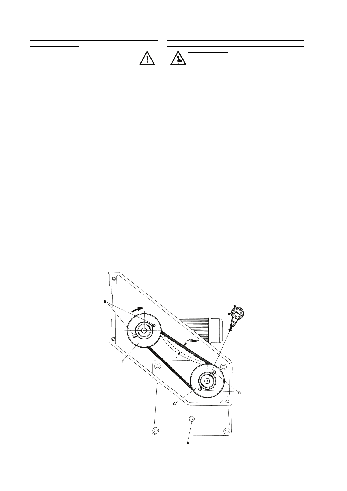
To measure and adjust the feed-in speed, remove the
upper cover of the bag feed-in device.
Start the feed-in device (the conveyor will run simultaneously) and measure the revolutions of the driven pulley (see Fig. 2).
Read on the revolutions versus speed diagram (Fig. 3),
which conveyor speed corresponds with the revolutions
measured on driven pulley, respectively how many
revolutions are necessary to correspond with the conveyor speed.
If the feed-in speed (revolutions of driven pulley) has to
be changed, proceed as follows:
Switch off bag feed-in device at the main switch.
Loosen screws (B, Fig. 2) of driving and driven pulley.
If the feed-in speed it too low and has to be increased,
screw out driven
the revolutions. Full and half revolutions are possible.
Then screw in the driving pulley (T, Fig. 2) with the
same amount of revolutions.
pulley (G, Fig. 2) accordingly. Count
SINCRONIZAR LA VELOCIDAD DEL ALIMENTADOR
DE SACOS CON LA VELOCIDAD DE LA CADENA DE
ALIMENTACION
La velocidad del alimentador de sacos se puede ajustar
de 11 a 23 m/min. resp. 9 a 16 m/min. a 50 Hz y 13 a 27
m/min. resp. 10 a 19 m/min. a 60 Hz. Dentro de estos rangos puede ajustarse a cualquier velocidad de la cadena de
alimentación.
Para medir y ajustar la velocidad del alimentador, remueva
la tapa superior del alimentador de sacos.
Arranque el alimentador (la cadena correrá simultáneamente) y mida las revoluciones de la polea impulsora
(Ver Fig. 2).
Compare las revoluciones de la polea contra el diagrama
de velocidad (Fig. 3), y seleccione la velocidad de la correa que corresponde con la de la polea impulsora.
Si la velocidad del alimentador (revoluciones de la polea
impulsora) debe ser cambiada, proceda de la siguiente
manera:
Apague el alimentador en el interruptor principal.
Suelte los tornillos (B, Fig. 2) del impulsor y la polea impulsora.
Si la velocidad del alimentador es muy lenta y debe ser
incrementada, saque la polea impulsora
cuadamente. Cuente las revoluciones. Revoluciones media y completa son posibles de conseguir. Monte de nuevo
la polea impulsora (T, Fig. 2) con la misma cantidad de
revoluciones.
(G, Fig. 2) ade-
FIG. 2
6

SYNCHRONIZING THE FEED-IN SPEED WITH THE
CONVEYOR SPEED (continued)
If the feed-in speed it too high and has to be reduced,
screw out the driving
Count the revolutions. Then screw in the driven pulley
(G, Fig. 2) with the same amount of revolutions.
Retighten screws (B, Fig. 2) on the flats of pulleys and
measure the revolutions on driven pulley (G, Fig. 2), to
check if the feed-in speed corresponds with the conveyor speed.
NOTE: The V-belt pulleys (G and T, Fig. 2) have to be
assembled aligned
Check the tension of the V-belt. The belt tension is correct, when the V-belt can be depressed manually by
15 mm (19/32 in.) (see Fig. 2).
To check if the speeds of the bag feed-in device and
the conveyor correspond, it is also possible to mark the
conveyor belt and to convey an empty bag through the
feed-in device. Both speeds should match.
NOTE: Depending on the conditions at site, e.g. bag
material, it is sometimes necessary to slightly increase
the speed of the bag feed-in device in relation to the
conveyor speed.
Remount the upper cover.
pulley (T, Fig. 2) accordingly.
with each other.
SINCRONIZAR LA VELOCIDAD DEL ALIMENTADOR
DE SACOS CON LA VELOCIDAD DE LA CADENA DE
ALIMENTACION (Continuación)
Si la velocidad del alimentador es muy alta y debe ser reducida, saque la polea impulsora (T, Fig. 2) adecuadamente. Cuente las revoluciones. Monte de nuevo la polea
impulsora (G, Fig. 2) con la misma cantidad de revoluciones.
Reajuste los tornillos (B, Fig. 2) en la parte plana de las
poleas impulsoras (G, Fig. 2), para verificar si la velocidad
del alimentador coincide con la de la correa.
Las correas en V (G y T, Fig. 2) deben ser monta-
NOTA:
das alineadas
Verifique la tensión de la correa en V. La tensión de la correa es correcta, cuando se pueda hundir presionando un
poco con la mano 15 mm (Ver Fig. 2).
Para verificar si la velocidad del alimentador de sacos y la
cadena coinciden, también es posible marcar la correa de
alimentación y entrar un saco vacío a través del alimentador . Ambas velocidades beberían coincidir.
NOTA:
trabajo y/o el material del saco, algunas veces puede ser
necesario incrementar ligeramente la velocidad del alimentador en relación a la velocidad de la correa.
Monte la cubierta superior de nuevo.
una con la otra!
Dependiendo de las condiciones en el lugar de
FIG. 3
7
TIGHTENING AND ADJUSTING THE CHAINS
Switch off bag feed-in device at the
main switch!
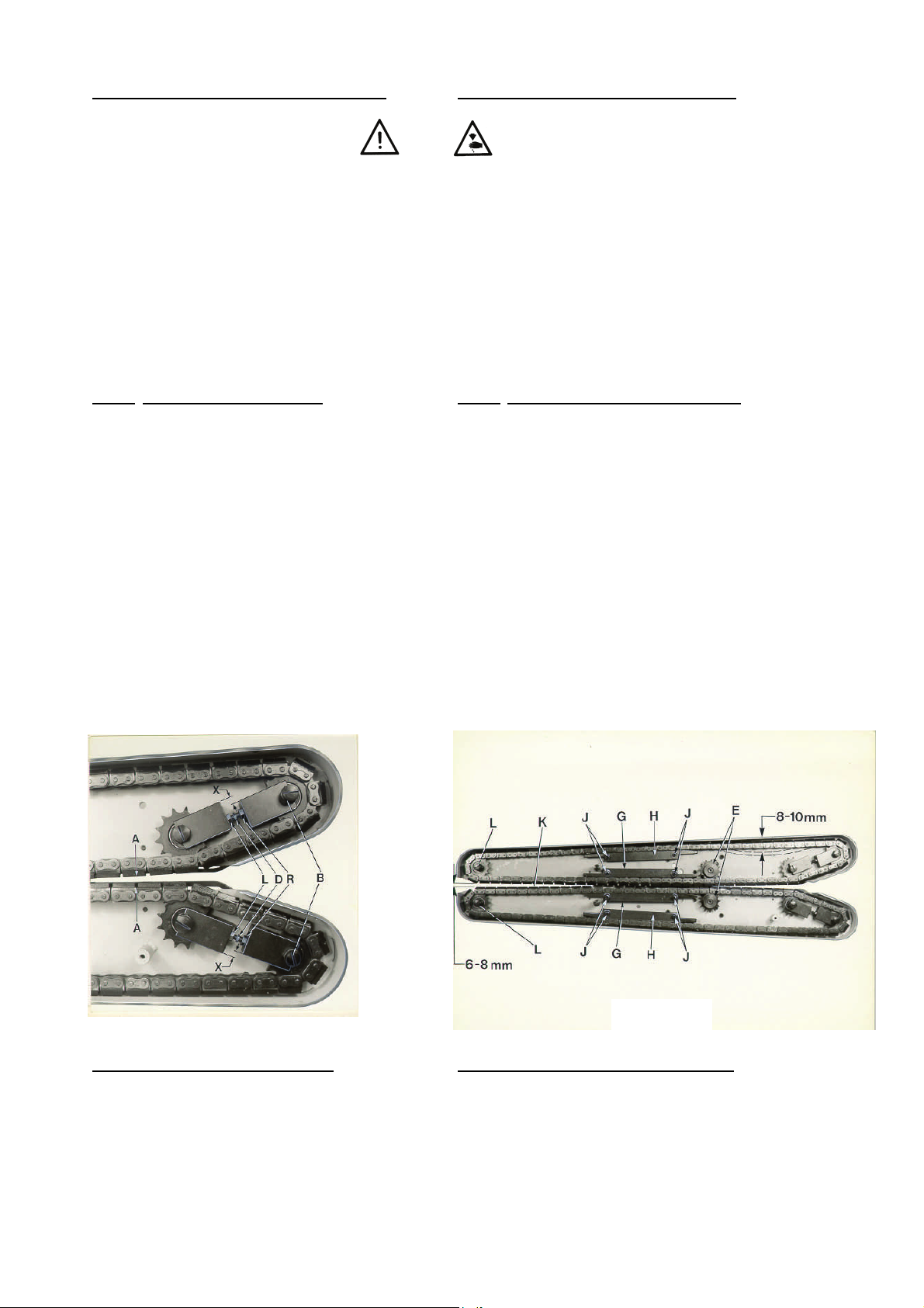
Remove the two lower chain covers (A, Fig. 1). Mount
the two chains so, that the chain links are offset to each
other and the gaps between the chain links are positioned approx. within the center of the chain links of the
opposite chain (A, Fig. 4).
After loosening the two nuts (B, Fig. 4) on the top of
carrier plates and the nuts (L and R, Fig. 4) the chains
can be tightened with threaded bolts (D, Fig. 4). Caution, nuts (L, Fig. 4) have a left hand thread. the chains
should be tightened just so, that they can be depressed
manually by 8 to 10 mm (5/16 to 25/64 in.) (see Fig.
4A).
NOTE:
Do not over tighten chains. This may cause
chain breaking as well a damages on the carrier plates
and the motor.
The chain adjusters have to be mounted offset to each
other (see X, Fig. 4). Retighten nuts (B, L and R, Fig.
4).
The chain guides (G and H, Fig. 4A) are adjustable after loosening screws (J, Fig. 4A) Set the two inner
chain guides (G, Fig. 4A) parallel to each other and so
that the chains are not pushed away from the sprockets
(E, Fig. 4A). The sprockets must engage fully between
the rolls of the chain links.
Set the two outer chain guides (H, Fig. 4A), without
presser, parallel and close to the chains. Retighten
screws (J, Fig. 4A) and mount the covers.
APRETADO Y AJUSTE DE LAS CADENAS
Apague el alimentador en el interruptor
principal!
Desmonte las dos cubiertas inferiores de las cadenas (A,
Fig. 1). Monte las cadenas de manera tal que los dientes
de la cadena queden uno frente al otro y las separaciones
entre los dientes estén posicionadas aproximadamente
dentro del centro de los dientes de la cadena opuesta (A,
Fig. 4).
Después de aflojar las dos tuerca (B, Fig. 4) en la parte
superior de la plancha transportadora y las tuercas (L y R,
Fig. 4), las cadenas pueden ser apretadas con los pernos
de ajuste (D, Fig. 4). Cuidado, las tuercas (L, Fig. 4) enroscan a la izquierda. Las cadenas deben ser ajustadas de
manera tal que al ser presionadas con la mano, se undir
de 8 a 10 mm (Ver Fig. 4A).
NOTA:
No apriete demasiado las cadenas. Esto puede
causar rotura de la cadena y daños en las planchas transportadoras y el motor.
Los ajustadores de las cadenas deben ser montados de
manera tal que queden uno frente al otro (Ver X, Fig. 4).
Apriete las tuercas (B, L y R, Fig. 4).
Las guías de las cadenas (G y H, Fig. 4A) pueden ser
ajustadas después de soltar los tornillos (J, Fig. 4A). Coloque las dos guías internas de las cadenas (G, Fig. 4A) paralelamente una a la otra de manera que las cadenas no
se salgan de los piñones (E, Fig. 4A). Los eslabones de
las cadenas deben encajar perfectamente en los piñones.
Ajuste las guías de las cadenas externas (H, Fig. 4A) sin
presión, paralelas y cerca a las cadenas. Apriete los tornillos (J, Fig. 4A) y monte nuevamente las cubiertas.
FIG. 4
ADJUSTING THE CHAIN PRESSURE
The presser of the front roller chain can be adjusted
with stop screw and lock nut (K, Fig. 1). The stop screw
is normally set so, that the chain in the front spring
loaded chain case just contacts the rear chain, without
exerting any pressure on it. Depending on the type and
thickness of the bag material, this setting sometimes
has to be changed slightly.
FIG. 4A
AJUSTE DE LA PRESION DE LA CADENA
La presión de la cadena frontal puede ser ajustada con el
tornillo tope y la contra tuerca (K, Fig. 1). El tornillo tope
normalmente esta ajustado de manera tal que la cadena
en el resorte frontal de la caja toca la cadena posterior
ligeramente, sin ejercer ninguna presión. Dependiendo
del tipo y grosor del material del saco a cerrar, este ajuste
debe cambiarse.
8
ADJUSTING THE CHAIN PRESSURE (continued)
In the sewing area of the sewing machine (K, Fig. 4A)
the chains of the bag feed-in device should only guide
the bag, to avoid an interference of the intermittent feed
of the sewing machine with the continuous feed ot the
bag feed-in device. Therefore the chains open in this
area by approx. 6 to 8 mm (15/64 to 5/16 in,) (see Fig.
4A). If necessary, this opening can be enlarged or reduced slightly after loosening nuts (L, Fig. 4A) on the
top of the chain cases. Retighten nuts (L, Fig. 4A) on
the top of the chain cases. Retighten nuts (L, Fig. 4A).
CAUTION!
during operation, because the chain may jump out of
the sprocket.
Do not pull the front chain case to the front
AJUSTE DE LA CADENA DE PRESION (Continuación)
En el área de costura de la máquina de coser (K, Fig. 4A)
las cadenas del alimentador de sacos solo deben guiar al
saco, para evitar cualquier interferencia de la alimentación
intermitente de la máquina de coser con el alimentador
continuo del alimentador de sacos. Sin embargo, las cadenas abren en esta área aproximadamente 6 a 8 mm (ver
Fig. 4A). De ser necesario, esta apertura puede alargarse
o reducirse ligeramente después de aflojar las tuercas (L,
Fig. 4A) en el tope de la caja de las cadenas. Apriete las
tuercas (L, Fig. 4A) de nuevo.
PRECAUCION!
durante operación, ya que éstas podrían salirse del piñón.
No hale el frente de la caja de las cadenas
ADJUSTING THE BAG-TOP FOLD-OVER DEVICE
The sword (1, page 18) and the deviating spiral (12,
page 18) are adjustable forwards and backwards as
well as in the height. The back side of the sword is
positioned in front of the throat plate surface of the
sewing machine depending on the thickness of the
bag. The upper edge of the sword is set approx 20 mm
above the sewing needle. The end of the folding
surface of the deviating spiral should match the throat
plate surface and has to be positioned close to the
sword with-out jamming the bag to be closed. The
guide (17, page 18) is used to control the height of the
folded edge of the bag top. Adjustments of the bag-top
fold-over device depend on the bag material .
ADJUSTING THE KNIVES AND TAPE FOLDER OF
BAG FEED-IN DEVICE NOS. G29910, GR29910,
GB29910, GBR29910 and GBR29920
Switch off bag feed-in device at the
main switch!
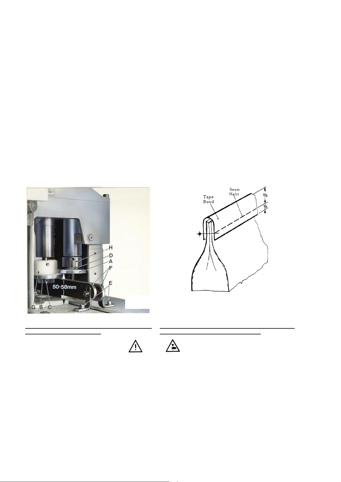
The cutting height of the knives is adjustable from 50 to
58 mm (1 31/32 to 2 9/32 in.), measured from the upper surface of chain case (see Fig. 5). The standard
setting is 54 mm (2 1/8 in.).
To replace the knives (A, B, Fig. 5), remove the chip
chute, the left hand guard and the two guide rails (F,
Fig. 5) which are fastened with four screws (E, Fig. 5).
Turn the knives in a position where the screw (C, Fig.
5) located in the hub of the lower knife (B, Fig. 5) is accessible from the left. Loosen screw (C, Fig. 5) with the
special screw driver No. 95620 and remove lower knife
(B, Fig. 5), upper knife (A, Fig. 5) and spring (D, Fig. 5).
NOTE:
There is no screw in the hub of the upper knife
(A, Fig. 5).
When assembling, slip spring (D, Fig. 5) and upper
knife (A, Fig. 5) on the front knife shaft. Turn the knife
to and fro, until the Woodruff key, cemented in the knife
shaft, engages with the key groove in the knife hub.
Hold upper knife in position. Slip the lower knife
AJUSTE DEL DOBLADILLADOR SUPERIOR
La espada (1, Página 18) y la espiral de desviación (12,
Página 18) pueden ajustarse tanto hacia adelante o hacia
atrás, como en su altura. La parte posterior de la espada
se ajusta en frente de la superficie de la plancha de aguja
de la máquina de coser dependiendo del grosor del saco.
La esquina superior de la espada esta ajustada aproximadamente a 20 mm sobre la aguja. El final de la superficie
del doblador de la espiral de desviación debe ajustarse lo
mas cerca posible a la espada sin que arrugue el saco a
cerrar. La guía (17, Página 18) se usa para controlar el
peso del borde doblado del tope del saco. Ajustes al dobladillador superior dependen del material del saco.
AJUSTE DE LAS CUCHILLAS Y EL ROLLO DE CINTA
DEL ALIMENTADOR DE SACOS Nº G29910, GR29910,
GB29910, GBR29910 y GBR29920
Apague el alimentador de sacos en el
interruptor principal.!
La altura de corte de las cuchillas se puede ajustar de 50 a
58 mm, medida desde la superficie superior de la caja de
las cadenas (ver Fig. 5). El ajuste estándar es de 54 mm.
Para cambiar las cuchillas (A, B, Fig. 5) retire el conductor
del chip, el protector izquierdo y los dos rieles guía (F, Fig.
5), que están atornillados con cuatro tornillos (E, Fig. 5).
Mueva las cuchillas a una posición donde el tornillo (C,
Fig. 5) localizado en el centro de la cuchilla inferior (B, Fig.
5) sea accesible desde la izquierda. Suelte el tornillo (C,
Fig. 5) con el destornillador especial parte Nº 95620 y retire la cuchilla inferior (B, Fig. 5), la cuchilla superior (A, Fig.
5) y el resorte (D, Fig. 5).
La cuchilla superior no tiene un tornillo en su cen-
NOTA:
tro (A, Fig. 5).
Para montar las cuchillas, deslice el resorte (D, Fig. 5) y la
cuchilla superior (A, Fig. 5) en el eje de la cuchilla frontal.
Muévala hacia delante y hacia atrás hasta que la cuña,
cementada en el eje de la cuchilla, ajuste con el canal en
el centro de la cuchilla. Mantenga la cuchilla en esta posición y deslice la cuchilla inferior B, Fig. 5) en el eje de la
9
(B, Fig. 5) on the rear knife shaft, so that the Woodruff
key engages with key slot, and push the lower knife
with the upper knife up to the stop on plastic collar (G,
Fig. 5). Tighten screw (C, Fig. 5) in the hub of the lower
knife securely. The collar (G, Fig. 5) serves as a stop
for the set cutting height of the knives. Therefore, it is
not necessary to readjust the height when replacing the
knives. It also prevents the cut-off bag strips from being
wound-up on the knife shaft. The pressure exerted by
the upper knife on the lower knife can be reduces or
increased by raising or lowering collar (H, Fig. 5).
Reassemble the two guide rails (F, Fig. 5), the left hand
guard and the chip chute. The chip chute should be set
as close as possible to the lower knife without contacting the knives, the knife shafts or the collars.
The tape folder has to be positioned close to the sewing machine and aligned with the throat plate surface
on sewing machine. The height should be adjusted so
that the tape fully covers the bag opening and the
seam is located in the lower third of the tape (see Fig.
6).
cuchilla posterior, de manera que la cuña encaje en la ranura, y empuje la cuchilla inferior con la cuchilla superior hasta
que las pare el aro de plástico (G, Fig. 5). Apriete el tornillo
(C, Fig. 5) en el centro de la cuchilla inferior para asegurarla.
El aro de plástico (G, Fig. 5) sirve como parada en el ajuste
de la altura de las cuchillas. Sin embargo, no es necesario
ajustar esta altura cuando se cambien las cuchillas. También sirve para evitar que los restos de la cadeneta después
de terminado el saco entren en el eje de las cuchillas. La
presión de la cuchilla superior sobre la inferior puede reducirse o incrementarse subiendo o bajando el aro de plástico
(H, Fig. 5).
Monte el riel de dos guías (F, Fig. 5), el protector izquierdo y
el protector del chip. El protector del chip debe quedar lo
mas cerca posible de la cuchilla inferior sin tocar las cuchillas, los ejes o los aros.
El rollo de cinta debe ser montado cerca a la máquina de
coser y alineado con la superficie de la plancha de aguja de
la máquina de coser. La altura debe ajustarse de manera tal
que la cinta cubra totalmente la apertura del saco y la costura quede a una altura de un tercio de la cinta (ver Fig. 6).
FIG. 5
ADJUSTING THE KNIVES OF BAG FEED-IN DEVICE
NOS. GB29915 AND GBR29915
Switch off bag feed-in device at the
main switch!
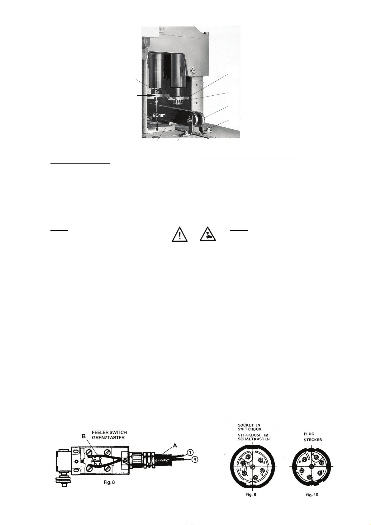
The cutting height of the knives is adjustable from 86 to
94 mm ( 3 25/64 to 3 45/64 in.), measured from the upper surface of chain case (see Fig. 7). The standard
setting is 90 mm (3 35/64 in.).
To replace the knives (A, Fig. 7), remove the chip
chute, the left hand guard and the two guide rails (E,
Fig. 7) which are fastened with four screws (D, Fig. 7).
Turn the knives in a position where the screws (B, C,
Fig. 7) located in the hub of the knives are accessible
from the left. Loosen screws (B, C, Fig. 7) with the special screw driver No. 95620 and remove the knives.
FIG. 6
AJUSTE DE LAS CUCHILLAS DEL AIMENTADOR DE
SACOS MODELOS GB29915 y GBR29915
Apague el alimentador de sacos en el
interruptor principal.!
La altura de corte de las cuchillas se puede ajustar de 86
a 94 mm, medidos desde la superficie de la caja de las
cadenas (ver Fig. 7). La altura estándar es de 90 mm.
Para cambiar las cuchillas (A, Fig. 7) retire el conductor
del chip, el protector izquierdo y los dos rieles guía (E, Fig.
7), que están atornillados con cuatro tornillos (D, Fig. 7).
Mueva las cuchillas a una posición donde los tornillos (B,
C, Fig. 7) localizados en el centro de las cuchillas sean
accesibles desde la izquierda. Suelte los tornillos (B, C,
Fig. 7) con el destornillador especial parte Nº 95620 y retire las cuchillas.
10
B
A
A
D E
PRE-FEELER SWITCH
The bag feed-in devices are fitted with a pre-feeler
switch to enable an earlier start of the automatic sewing machine. This feeler switch starts sewing before the
incoming bag reaches the feeler of the sewing machine. This prevents break-downs of the sewing machine.
Mounting
NOTE: The operations described in the
following have to be done by an electrician.
Connect cable (A, Fig. 8) with plug (Fig. 10) according
to Fig. 8 to the feeler switch (B, Fig. 8).
The socket contacts of the receptacle (Fig. 9) for the
pre-feeler switch are connected in the same way as the
socket contacts of the receptacle for the proximity
switch of the sewing machine in the switch box of the
column. For connections refer to the wiring diagram,
contained in the switch box of each column and catalog
Nos. 280BC for the automatic sewing machines class
BC100 respectively No. 280 for the automatic sewing
machines class 80800.
When assembling the receptacle choose built-in position “A” (see Fig. 9), i.e. screw driver slot and the letter
“A” on the contact insert must point to the wide stay on
the receptacle housing after being pushed in and
locked.
Solder the three socket contacts on the corresponding
cable leads and press the contacts accordingly in the
holes marked 1, 2 and 4 of the receptacle as well as the
four sealing plugs in the holes marked A, 3, 5 and 6.
When the pre-feeler switch is not in use, cover the receptacle with the protection cap to avoid contamination.
C
E
D
FIG. 7
INTERRUPTOR DEL PRE-PALPADOR
El alimentador de sacos tiene incorporado un interruptor
del pre palpador que permite arrancar la maquina de coser
automáticamente. Este interruptor arranca a coser antes
de que el saco alcance el palpador de la maquina de coser. Sirve para prevenir interrupciones en la costura.
Montaje
Conecte el cable (A, Fig. 8) con el enchufe (Fig. 10) al interruptor del palpador (B. Fig. 8) de acuerdo al diagrama
de la Fig. 8.
Los contactos del receptáculo (Fig. 9) del interruptor del
pre palpador están conectados en la misma manera que
los del receptáculo del interruptor de proximidad de la maquina de coser en la caja de interruptores de la columna.
Para conexiones, refiérase al diagrama de cableado de la
caja de interruptores, que aparece en el catalogo Nº
280BC para las maquinas automáticas de la clase BC100
y Nº 280 para las maquinas automáticas de la clase
80800, respectivamente.
Al montar el receptáculo, seleccione la posición pre determinada „A“ (ver Fig. 9). Puede utilizar la punta de un destornillador para mover y bloquear la selección a la letra „A“
en la carcasa del receptáculo.
Suelde los tres contactos del enchufe a los cables correspondientes y presione los contactos en los huecos marcados con los números 1, 2 y 4. De la misma manera, selle
los huecos marcados A, 3, 5 y 6.
Cuando el interruptor del pre palpador no se esté usando,
cúbralo con las cubierta de protección para evitar contaminación.
NOTA: Las operaciones descritas a conti-
nuación deben ser realizadas por un electricista!
11

ASSEMBLY OF CHAIN GUIDE AND SPROCKET
GEARS
MONTAJE DE LA CADENA GUIA Y LOS PIÑONES DEL
ENGRANAJE
BLOWER DEVICE
Bag feed-in device Nos. G29910, GR29910, GB29910,
GBR29910, GB29915, GBR29915 and GBR29920 are
equipped with a blower for the trimmings.
During the time of being fed through the bag feed-in
device, the bag switches on the air blast by means of a
whisker valve.
The air blast can be regulated on hollow bolt with throttle check valve (A, page 30).
The necessary working pressure for the blower device
is 3 to 4 bar (44 to 59 psi). Mounting see page 30.
Filtered, oil-free compressed air is required.
ORDERING WEAR AND SPARE PARTS
This catalog has been arranged to simplify ordering
wear and spare parts. Views of various sections of the
mechanism are shown so that the parts may be seen in
their actual position in the bag feed-in device. On the
page opposite the illustration will be found a listing of
parts with their part numbers, descriptions and the
number of pieces required in the particular view being
shown.
Numbers in the first column are reference numbers
only, and merely indicate the position of that part in the
illustrations. Reference numbers should never be used
in ordering parts. Always use the part number listed in
the second column.
Component parts of sub-assemblies which can be furnished for repairs are indicated by indenting their descriptions under the description of the main subassembly.
IMPORTANT:
PART NUMBER, PART NAME AND STYLE OF BAG
FEED-IN DEVICE FOR WHICH PART IS ORDERED.
ON ALL ORDERS, PLEASE INCLUDE
SOPLADOR
El alimentador de sacos modelos Nos. G29910, GR29910,
GB29910, GBR29910, GB29915, GBR29915 y
GBR29920 viene equipado con un soplador para eliminar
los residuos de las costuras.
Cuando el saco entra en el alimentador, se activa la válvula que controla el interruptor de la ráfaga de aire.
Esta ráfaga de aire se controla regulando el perno hueco
de la válvula reguladora (Página 30).
La presión necesaria para el mecanismo del soplador es
de 3 a 4 bar. Para montaje, ver página 30.
Se requiere de aire comprimido, filtrado, sin aceite, para el
correcto funcionamiento de este equipo.
PEDIDO DE PIEZAS DE REPUESTO
Este catálogo fue diseñado para facilitar los pedidos de los
repuestos. Los dibujos de grupos específicos del mecanismo demuestran la posición de las piezas en la máquina de
coser. En la página en frente de la página de la ilustración
se encuentra un listado de las piezas con su número de
repuesto, descripción y la cantidad requerida para la sección indicada.
Los números de la primera columna son números de referencia e indican donde se encuentra la piezas en la ilustración. Los números de referencia no se deben utilizar en sus
pedidos de repuestos. Utilice siempre el número de repuesto de la segunda columna.
Componentes de piezas compuestas que se pueden suministrar como repuestos se encuentran diferenciadas de tal
forma que las descripciones están desplazadas hacia la
derecha referente a la descripción de la pieza compuesta.
IMPORTANTE
POR FAVOR EL NUMERO Y LA DESCIPCION DE LA
PIEZA Y EL ESTILO DE MAQUINA PARA CUAL SE ORDENA LA PIEZA.
! EN TODAS LAS ORDENES INCLUYA
12

VIEWS AND DESCRIPTIONS
OF PARTS
VISTAS Y DESCRIPCION DE
LAS PARTES Y PIEZAS
13

14

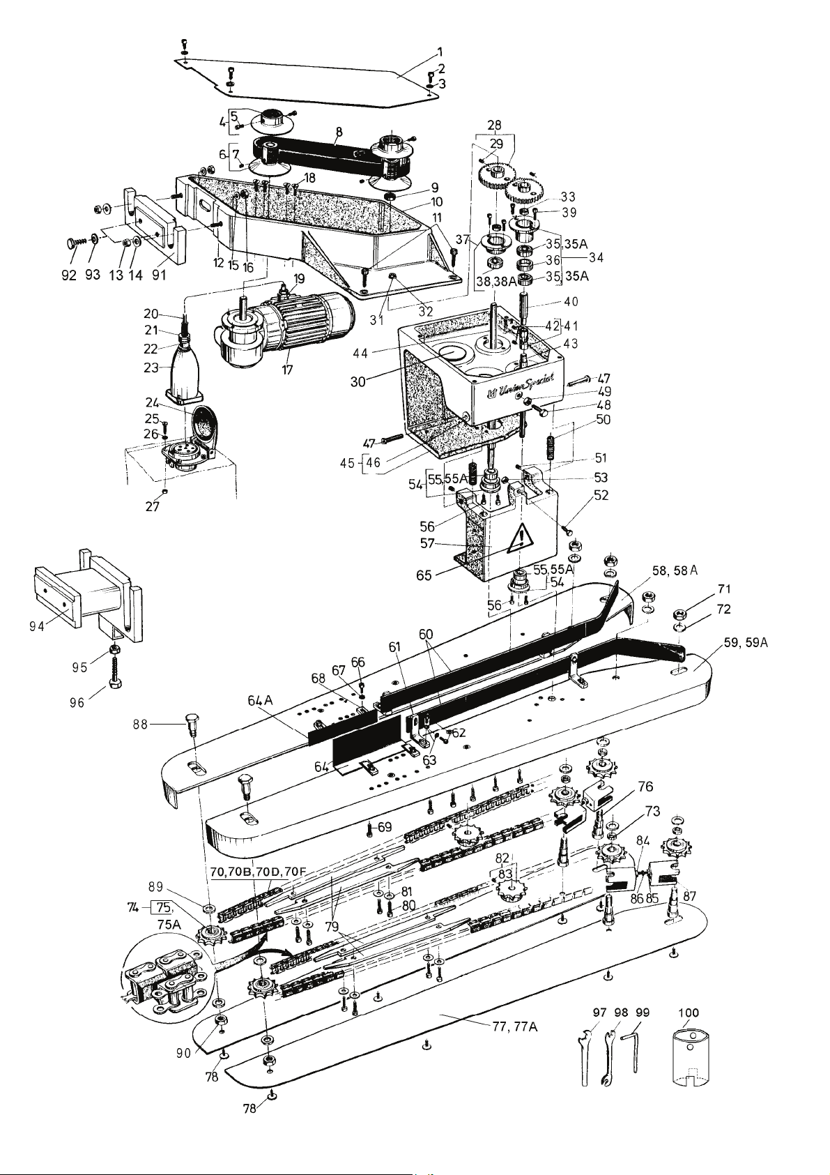
BAG FEED-IN DEVICE NOS. G29905, GR29905, GB29905 AND GBR29905
ALIMENTADOR DE SACOS Nos. G29905, GR29905, GB29905 Y GBR29905
Ref. No. Part No. Description Descripción Amt. req.
Ref. Nº Parte Nº Cant.Req.
1 - 101 G29905G, Bag Feed-in Device Alimentador de sacos 1
GB29905G 220-240/380-415 V, 3 phase, 50 Hz 220-240/380-415 V, Trifásico, 50 Hz 1
Speed: 11-23 m/min., I = 30:1 Velocidad: 11-23 m/min., I = 30:1
243-277/420-480 V, 3 phase, 60 Hz 243-277/420-480 V, Trifásico, 60 Hz
Speed: 13-27 m/min., I = 30:1 Velocidad: 13-27 m/min., I = 30:1
GR29905G, Bag Feed-in Device Alimentador de sacos 1
GBR29905G 220-240/380-415 V, 3 phase, 50 Hz 220-240/380-415 V, Trifásico, 50 Hz 1
Speed: 9-16 m/min., I = 38:1 Velocidad: 9-16 m/min., I = 38:1
243-277/420-480 V, 3 phase, 60 Hz 243-277/420-480 V, Trifásico, 60 Hz
Speed: 10-19 m/min., I = 38:1 Velocidad: 10-19 m/min., I = 38:1
G29905X1, Bag Feed-in Device Alimentador de sacos 1
GB29905X1 220/440 V, 3 phase, 60 Hz 220/440 V, Trifásico, 60 Hz 1
Speed: 13-27 m/min., I = 30:1 Velocidad: 13-27 m/min., I = 30:1
GBR29905X1 Bag Feed-in Device Alimentador de sacos 1
220/440 V, 3 phase, 60 Hz 220/440 V, Trifásico, 60 Hz
Speed: 10-19 m/min., I = 38:1 Velocidad:10-19 m/min., I = 38:1
1 99631 Cover Cubierta 1
2 95413 Screw Tornillo 3
3 95951 Washer Arandela 3
4 99644 Pulley without Hub Polea sin cubo 2
5 95412 Screw Tornillo 4
6 99644A Pulley with Hub Polea con cubo 2
7 95205 Set Screw Tornillo de sujeción 2
8 999-107 V-Belt Correa en V 1
9 999-109 Lip Seal Empaquetadura 1
10 99627 Support Soporte 1
11 95408 Screw Tornillo 4
12 95675 Stud Perno 2
13 95251 Nut Tuerca 2
14 96900 Washer Arandela 2
15 96201 Spring Washer Arandela muelle 2
16 95251 Nut Tuerca 2
17 997G405 Gear Motor Motor de engranaje 1
220-240/380-415 V, 3 phase, 50 Hz 220-240/380-415 V, Trifásico, 50 Hz
243-277/420-480 V, 3 phase, 60 Hz 243-277/420-480 V, Trifásico, 60 Hz
I = 30:1 I = 30:1
997G401 Gear Motor Motor de engranaje 1
220-240/380-415 V, 3 phase, 50 Hz 220-240/380-415 V, Trifásico, 50 Hz
243-277/420-480 V, 3 phase, 60 Hz 243-277/420-480 V, Trifásico, 60 Hz
I = 38:1 I = 38:1
997X1-405 Gear Motor Motor de engranaje 1
220/440 V, 3 phase, 60 Hz 220/440 V, Trifásico, 60 Hz
I = 30:1 I = 30:1
997X1-401 Gear Motor Motor de engranaje 1
220/440 V, 3 phase, 60 Hz 220/440 V, Trifásico, 60 Hz
I = 38:1 I = 38:1
18 95145 Screw for Motor Tornillo del motor 4
19 998-337AK Reduction Reductor 1
20 998-313C Cable Screwing Cable atornillado 1
21 G 21233CJ Cable Cable 1
22 998-313J Cable Screwing Cable atornillado 1
23 998-257D Plug Enchufe 1
24 998-256D Socket Zócalo 1
25 95154V Screw Tornillo 4
26 96100 Lockwasher Arandela de presión 4
27 95257V Nut Tuerca 4
28 99642 Gear Engranaje 2
29 95205 Set Screw Tornillo de sujeción 1
30 999-78B Plug Tapón 2
31 999-21 Lubricating Nipple Tubo de lubricación 1
32 999-22 Lubricating Mark Punto de lubricación 1
33 99639D Spacer Sleeve Distanciador 2
Ref. Nos. 34 – 80 see page 17 Refs. Nos. 34 – 80 ver página 17
15

16

BAG FEED-IN DEVICE NOS. G29905, GR29905, GB29905 AND GBR29905
ALIMENTADOR DE SACOS Nos. G29905, GR29905, GB29905 Y GBR29905
Ref. No. Part No. Description Descripción Amt. req.
Ref. Nº Parte Nº
34 99640 Flange Bushing Assembly, upper Conj. Cojinete con pestaña, superior 1
35 999-106 Ball Bearing Cojinete de bolas 2
35A 999-106R Ball Bearing, stainless steel Cojinete de bolas, Acero inoxidable 2
36 99640D Spacer Sleeve Distanciador 1
37 99640A Flange Bushing Assembly, upper Conj. Cojinete con pestaña, superior 1
38 999-106 Ball Bearing Cojinete de bolas 1
38A 999-106E Ball Bearing, stainless steel Cojinete de bolas, Acero inoxidable 1
39 95412 Screw Tornillo 4
40 99641A Upper Shaft, driven Eje superior, engranaje 1
41 99643 Cardan Joint Junta del cardán 1
42 95205 Set Screw Tornillo de sujeción 2
43 99641B Lower Shaft, driven Eje inferior, engranaje 1
44 99641 Driving Shaft Eje impulsor 1
45 99628A Gear Box Caja de engranajes 1
46 99629 Bushing Bocina 2
47 99589A Stud Perno 2
48 95001 Hex. Head Screw Tornillo cabeza hexagonal 1
49 95251 Nut Tuerca 1
50 97010 Spring Resorte 2
51 95205 Set Screw for 99589A Tornillo de sujeción para 99589A 2
52 95051 Hex. Head Screw Tornillo cabeza hexagonal 1
53 95250 Nut Tuerca 1
54 99640B Flange Bushing Assembly, lower Conj. Cojinete con pestaña, inferior 2
55 999-106 Ball Bearing Cojinete de bolas 1
55A 999-106R Ball Bearing, stainless steel Cojinete de bolas, Acero inoxidable 1
56 95412 Screw Tornillo 4
57 99630 Swivel Arm Brazo oscilante 1
58 99634HB Carrier Plate, rear Caja cadenas, posterior 1
58A 99634HBK Carrier Plate, rear, short version Caja cadenas, posterior, versión corta 1
59 99634VB Carrier Plate, front Caja cadenas, anterior 1
59A 99634VBK Carrier Plate, front, short version Caja cadenas, anterior, versión corta 1
60 99635F Guide Rail Riel guía 2
61 99590E Bracket Soporte 4
62 95412 Screw Tornillo 8
63 HA20A Washer Arandela 8
64 99635KA Guide Plate, height: 80 mm Plancha guía, altura: 80 mm 2
64A 99635K Guide Plate, height: 30 mm Plancha guía, altura: 30 mm 2
65 999-125WA Warning Sign Aviso de precaución 1
66 95412 Screw Tornillo 4
67 HA20A Washer Arandela 4
68 99636 Clamp Sujetador 4
69 95403 Screw Tornillo 6
70 999-121A Roller Chain, U-type with rubber Cadena tipo U, con protectores de goma 2
70A 999-121AA Master Link for 999-121A ,not shown Diente principal para 999-121A, no se
70B 999-121AE Roller Chain, stainless steel, U-type
70C 999-121AEA Master Link for 999-121AE, not
70D 999-121L Roller Chain, L-type with rubber Cadena tipo L, con protectores de goma 2
70E 999-121LA Master Link for 999-121L, not shown Diente principal para 999-121L, no se
70F 999-121LK Roller Chain, short version , L-type
71 95290 Nut Tuerca 4
72 51244L Washer Arandela 8
73 99639D Spacer Sleeve Distanciador 4
74 99639G Sprocket Assembly Conj. Piñón 6
75 999-106 Ball Bearing Cojinete de bolas 1
75A 999-106E Ball Bearing, stainless steel Cojinete de bolas, Acero inoxidable 1
76 99638 Spacer Stud Perno distanciador 4
77 99632F Chain Guard Protector de la cadena 2
77A 99632EK Chain Guard, short version Protector de la cadena, versión corta 2
78 141 Screw Tornillo 8
79 99635G Chain Guide Guía de las cadenas 4
80 95403 Screw Tornillo 8
Ref. Nos. 81 – 101 see page 19 Refs. Nos. 81 – 101 ver página 19
with rubber
shown
with rubber
muestra en el dibujo.
Cadena, Acero inoxidable, protectores de
goma
Diente principal para 999-121AE, no se
muestra en el dibujo.
muestra en el dibujo.
Cadena, versión corta, tipo L, con protec-
tores de goma
Cant.Req.
1
2
1
1
2
17
18

BAG FEED-IN DEVICE NOS. G29905, GR29905, GB29905 AND GBR29905
ALIMENTADOR DE SACOS Nos. G29905, GR29905, GB29905 Y GBR29905
Ref. No. Part No. Description Descripción Amt. req.
Ref. Nº Parte Nº
81 96902 Washer Arandela 8
82 99639TA Sprocket, 12 teeth Piñón, 12 dientes 2
83 95205 Set Screw Tornillo de sujeción 1
84 269 Nut, lefthand thread Tuerca, enrosca a la derecha 2
85 18 Nut Tuerca 2
86 51240D Stud for Chain Adjuster Perno para ajustar la cadena 2
87 99619A Chain Adjuster Fork Tridente para ajustar la cadena 4
88 99373D Hex. Head Screw Tornillo cabeza hexagonal 2
89 99639E Washer Arandela 4
90 95253 Nut Tuerca 2
91 99627A Bracket for Feed-in Device Soporte alimentador de sacos 1
92 95022 Hex. Head Screw Tornillo cabeza hexagonal 2
93 95953 Washer Arandela 2
94 99627B Bracket for Feed-in Device Soporte alimentador de sacos 1
95 95251 Nut Tuerca 1
96 95028A Hex. Head Screw Tornillo cabeza hexagonal 1
97 21388 Wrench, size 9.5 mm Llave, tamaño 9,5 mm 1
98 95633B Wrench, size 5/16” x 3/8” Llave, tamaño 5/16 x 3/8 1
99 95601 Allen Wrench size 4 mm Llave Allen, tamaño 4 mm 1
100 95641 Wrench for Belt Drive Llave para correa del alimentador 1
101 29926A Pre-Feeler Switch, not shown, Interruptor del pre palpador, no se mues-
tra
see pages 30 and 31 ver páginas 30 y 31
CHAIN TENSION ADJUSTER, SPRING LOADED
AJUSTE DE LA TENSION DE LAS CADENAS
Cant.Req.
1
1 V99619B Chain Tension Adjuster Ajustador de tensión de las cadenas 1
2 1021U Washer Arandela 1
3 95578 Nut Tuerca 1
4 95290 Nut Tuerca 1
5 99619C Sleeve Manga 1
6 97020 Spring Resorte 1
7 99619B Fork Tridente 1
8 99365BA145 olt Correa 1
9 95953 Washer Arandela 1
10 99619D Holder Sujetador 1
11 96669 Roll Pin Pasador de seguridad 1
12 95290 Nut Tuerca 1
13 51244L Washer Arandela 3
14 99639D Spacer Sleeve Manga distanciadora 1
15 99638 Spacer Stud Perno distanciador 1
16 99639G Sprocket Assembly Conj. Piñón 1
17 999-106 Ball Bearing
Cojinete de bolas
19
1

20

BAG-TOP FOLD-OVER DEVICE 93051FA*
DOBLADILLADOR SUPERIOR 93051FA*
Ref. No. Part No. Description Descripción Amt. req.
Ref. Nº Parte Nº
1 93051FB1 Sword Espada 1
2 93051FB2 Bracket Soporte 1
3 95115 Screw Tornillo 2
4 96207 Locking Ring Anillo de retención 2
5 95255 Nut Tuerca 3
6 93051F1A Connection Conexión 1
7 95117 Screw Tornillo 1
8 96207 Locking Ring Anillo de retención 1
9 93051EB2 Guide Guía 1
10 95412 Screw Tornillo 4
11 HA20A Washer Arandela 10
12 93051FB3 Deviating Spiral Espiral de desviación 1
13 93051F3A Bracket Soporte 1
14 95412 Screw Tornillo 2
15 95403A Screw Tornillo 2
16 93051FB7 Guide Guía 1
17 93051F6 Guide Guía 1
18 95412B Screw Tornillo 2
19 93051E4 Bracket Soporte 1
20 93051E5 Bracket Soporte 1
21 95403 Screw Tornillo 2
22 96902 Washer Arandela 2
Cant.Req.
* Extra order and charge item for bag feed-in device
Nos. GB29905 and GBR29905.
* Piezas tiene que ser ordenadas y pagadas por separado
en los alimentadores de sacos Nos. GB29905 y
GBR29905.
21

22

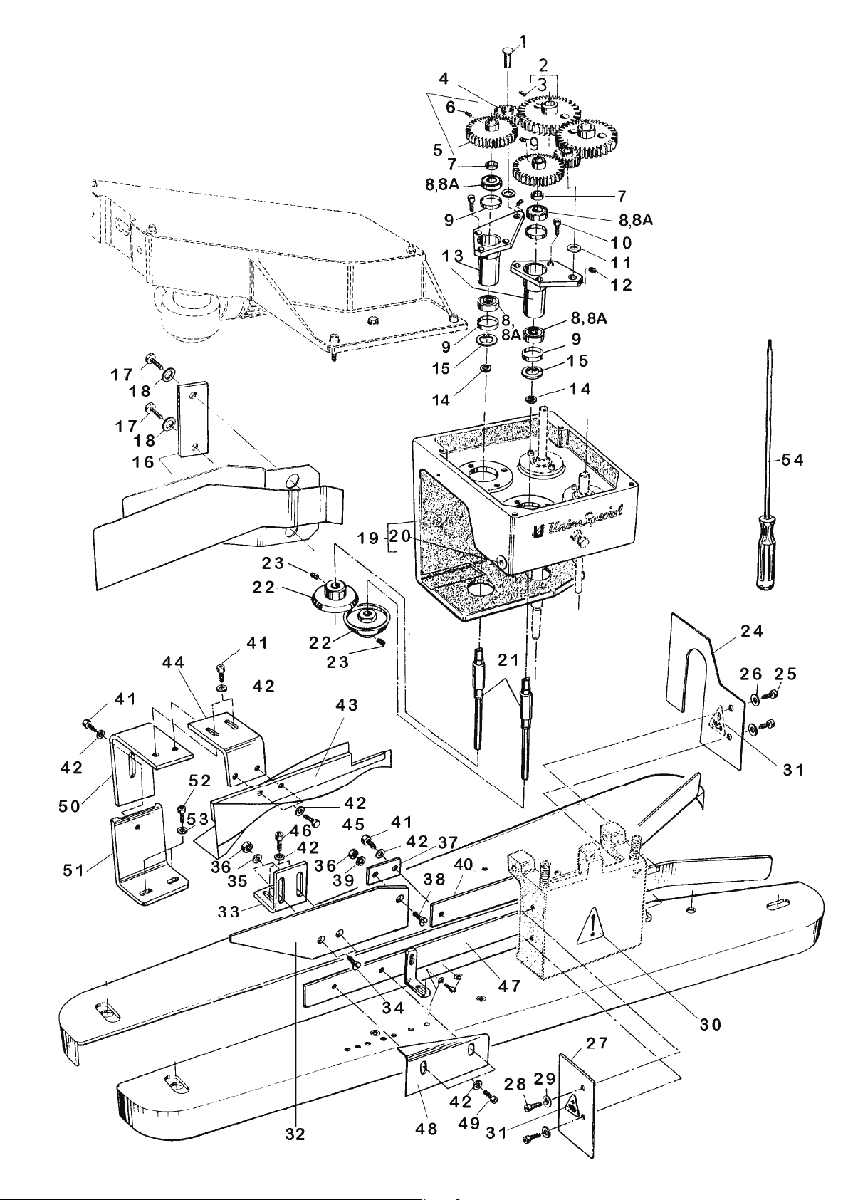
BAG FEED-IN, TRIMMING AND TAPING DEVICE NOS. G29910, GR29910, GB29910 AND GBR29910
ALIMENTADOR DE SACOS, CORTADOR Y COLOCADOR DE CINTAS Nos. G29910, GR29910, GB29910 Y GBR29910
Ref. No. Part No. Description Descripción Amt. req.
Ref. Nº Parte Nº
1 - 49 G29910G, Bag Feed-in Device Alimentador de sacos 1
GB29910G 220-240/380-415 V, 3 phase, 50 Hz 220-240/380-415 V, Trifásico, 50 Hz 1
Speed: 11-23 m/min., I = 30:1 Velocidad: 11-23 m/min., I = 30:1
243-277/420-480 V, 3 phase, 60 Hz 243-277/420-480 V, Trifásico, 60 Hz
Speed: 13-27 m/min., I = 30:1 Velocidad: 13-27 m/min., I = 30:1
GR29910G, Bag Feed-in Device Alimentador de sacos 1
GBR29910G 220-240/380-415 V, 3 phase, 50 Hz 220-240/380-415 V, Trifásico, 50 Hz 1
GBR29920G Speed: 9-16 m/min., I = 38:1 Velocidad: 9-16 m/min., I = 38:1
243-277/420-480 V, 3 phase, 60 Hz 243-277/420-480 V, Trifásico, 60 Hz
Speed: 10-19 m/min., I = 38:1 Velocidad: 10-19 m/min., I = 38:1
GB29910X1 Bag Feed-in Device Alimentador de sacos 1
220/440 V, 3 phase, 60 Hz 220/440 V, Trifásico, 60Hz
Speed: 13-27 m/min., I = 30:1 Velocidad: 13-27 m/min., I = 30:1
GBR29910X1 Bag Feed-in Device Alimentador de sacos 1
220/440 V, 3 phase, 60 Hz 220/440 V, Trifásico, 60 Hz
Speed: 10-19 m/min., I = 38:1 Velocidad: 10-19 m/min., I = 38:1
1 99532B Stud Perno 2
2 99642 Gear Engranaje 2
3 95205 Set Screw Tornillo de sujeción 1
4 99642D Intermediate Gear Engranaje intermedio 2
5 99642B Gear Engranaje 2
6 95205 Set Screw Tornillo de sujeción 1
7 99639D Spacer Sleeve Distanciador 2
8 999-106 Ball Bearing Cojinete de bolas 4
8A 999-106R Ball Bearing, stainless steel Cojinete de bolas, Acero inoxidable 4
9 999-122 Compensating Ring Aro de compensación 4
10 95412 Screw Tornillo 6
11 54274P Washer Arandela 2
12 95515 Set Screw Tornillo de sujeción 2
13 99640J Bushing Bocina 2
14 999-106X Thrust Ball Bearing Cojinete de bolas 2
15 96163A Supporting Ring Arandela de soporte 2
16 96258 Retaining Ring Anillo retenedor 1
17 96172 Retaining Ring Anillo retenedor 1
18 99584AC Chip Chute Conductor del chip 1
18A 99590E Bracket Soporte 1
19 95413 Screw Tornillo 4
20 HA20B Washer Arandela 4
21 99641J Knifeshaft Eje de la cuchilla 2
22 96378 Woodruff Key Cuña 2
23 99641JA Set Collar Anilla 1
24 95500 Set Screw Tornillo de sujeción 1
25 97010B Spring Resorte 1
26 99670KA Knife Cuchilla 2
27 95500 Setscrew for Lower Knife Tornillo de sujeción cuchilla inferior 1
28 99641JB Set Collar Anilla 1
29 95500 Set Screw Tornillo de sujeción 1
30 99632C Hand Guard, right Protector de mano, derecho 1
31 95412 Screw Tornillo 2
32 95955 Washer Arandela 2
33 99632DA Hand Guard, left Protector de mano, izquierdo 1
34 95412 Screw Tornillo 2
35 95955 Washer Arandela 2
36 999-125WB Warning Sign Hand Aviso de precaución, manos 2
37 999-125WA Warning Sign Aviso de precaución 1
NOTE: Parts which are not illustrated and
listed are the same as for bag feed-in
devices shown on pages 14 to 19.
NOTA: Las piezas que no aparecen listadas aquí,
son las mismas de los alimentadores de sacos mostrados en las páginas 14 a la 19.
Cant.Req.
23

24

BAG FEED-IN, TRIMMING AND TAPING DEVICE NOS. G29910, GR29910, GB29910 AND GBR29910
ALIMENTADOR DE SACOS, CORTADOR Y COLOCADOR DE CINTAS Nos. G29910, GR29910, GB29910 Y
GBR29910
BAG FEED-IN AND TRIMMING DEVICE NO. GBR29920
ALIMENTADOR DE SACOS Y CORTADOR DE CINTA No. GBR29920
Ref. No. Part No. Description Descripción Amt. req.
Ref. Nº Parte Nº
38 95054 Hex. Head Screw Tornillo cabeza hexagonal 2
39 1021U Washer Arandela 2
40 A8852BA Bracket Soporte 1
41 A8852BB Adjustable Bracket Soporte, ajustable 1
42 95051 Screw Tornillo 6
43 96902 Washer Arandela 6
44 A8852BC Folder Bracket Soporte del dobladillador 1
45 99628A Gear Box Caja del engranaje 1
46 99629 Bushing Bocina 2
47 A8852A50 Paper Tape Folder for 50 mm wide tape Dobladillador para cintas de 50 mm de ancho 1
Cant.Req.
A8852A55 Paper Tape Folder for 55 mm wide
A8852A60 Paper Tape Folder for 60 mm wide
A8852A63 Paper Tape Folder for 63 mm wide tape Dobladillador para cintas de 63 mm de ancho 1
A8852A65 Paper Tape Folder for 65 mm wide tape Dobladillador para cintas de 65 mm de ancho 1
tape
A8852A70 Paper Tape Folder for 70 mm wide Dobladillador para cintas de 70 mm de ancho 1
tape
48 95620 Screw Driver Destornillador 1
49 29927P Blower Device, not shown,
tape
tape
see pages 34 and 35
Dobladillador para cintas de 55 mm de ancho 1
Dobladillador para cintas de 60 mm de ancho 1
Soplador, no se muestra en el dibujo,
ver páginas 34 y 35
1
A Cemented in the lower key slot. A Cementadas en la ranura de la caja inferior.
B Cemented in the upper key slot. B Cementadas en la ranura de la caja superior.
C The smaller inner diameter of thrust ball bearing C El minimo diametro interno del Cojinete de bolas en la boci-
in the rear bushing must be up when assembling. na posterior, debe ser aumentado cuando se monte.
D The bigger inner diameter of thrust ball bearing D El diametro maximo interno del Cojinete de bolas en la boci in the front bushing must be up when assembling. na anterior, debe ser aumentado cuando se monte.
25
26

BAG FEED-IN, TRIMMING AND FOLD OVER DEVICE NOS. GB29915 AND GBR29915
ALIMENTADOR DE SACOS, CORTADOR Y COLOCADOR DE CINTAS Nos. GB29915 Y GBR29915
Ref. No. Part No. Description Descripción Amt. req.
Ref. Nº Parte Nº
Cant.Req.
1 - 55 GB29915G Bag Feed-in Device Alimentador de sacos 1
220-240/380-415 V, 3 phase, 50Hz 220-240/380-415 V, Trifásico, 50 Hz
Speed: 11-23 m/min., I = 30:1 Velocidad: 11-23 m/min., I = 30:1
243-277/420-480 V, 3 phase, 60Hz 243-277/420-480 V, Trifásico, 60 Hz
Speed: 13-27 m/min., I = 30:1 Velocidad: 13-27 m/min., I = 30:1
GBR29915G Bag Feed-in Device Alimentador de sacos 1
220-240/380-415 V, 3 phase, 50Hz 220-240/380-415 V, Trifásico, 50 Hz
Speed: 9-16 m/min., I = 38:1 Velocidad: 9-16 m/min., I = 38:1
243-277/420-480 V, 3 phase, 60Hz 243-277/420-480 V, Trifásico, 60 Hz
Speed: 10-19 m/min., I = 38:1 Velocidad: 10-19 m/min., I = 38:1
GB29915X1 Bag Feed-in Device Alimentador de sacos 1
220/440 V, 3 phase, 60 Hz 220/440 V, Trifásico, 60 Hz
Speed: 13-27 m/min., I = 30:1 Velocidad: 13-27 m/min., I = 30:1
GBR29915X1 Bag Feed-in Device Alimentador de sacos 1
220/440 V, 3 phase, 60 Hz 220/440 V, Trifásico, 60 Hz
Speed: 10-19 m/min., I = 38:1 Velocidad: 10-19 m/min., I = 38:1
1 99532B Stud Perno 2
2 99642 Gear Engranaje 2
3 95205 Set Screw Tornillo de sujeción 1
4 99642D Intermediate Gear Engranaje intermedio 2
5 99642B Gear Engranaje 2
6 95205 Set Screw Tornillo de sujeción 1
7 99639DB Spacer Sleeve Distanciador 2
8 999-106 Ball Bearing Cojinete de bolas 4
8A 999-106R Ball Bearing, stainless steel Cojinete de bolas, Acero inoxidable 4
9 999-122 Compensating Ring Aro de compensación 4
10 95412 Screw Tornillo 6
11 54274P Washer Arandela 2
12 95515 Set Screw Tornillo de sujeción 2
13 99640BJ Bushing Bocina 2
14 96253 Retaining Ring Anillo retenedor 2
15 96172 Retaining Ring Anillo retenedor 2
16 99584AB Chip Chute with Washer Plate Conductor del chip con arandela 1
17 95051 Hex. Head Screw Tornillo cabeza hexagonal 2
18 96902 Washer Arandela 2
19 99628A Gear Box Caja del engranaje 1
20 99629 Bushing Bocina 2
21 99641BJ Knifeshaft Eje de la cuchilla 2
22 99670KA Knife Cuchilla 2
23 95500 Set Screw Tornillo de sujeción 2
24 99632C Hand Guard, right Protector de mano, derecho 1
25 95412 Screw Tornillo 2
26 95955 Washer Arandela 2
27 99632DA Hand Guard, left Protector de mano, izquierdo 1
28 95412 Screw Tornillo 2
29 95955 Washer Arandela 2
30 999-125WB Warning Sign Hand Aviso de precaución, manos 2
31 999-125WA Warning Sign Aviso de precaución 1
32-53 93051FB Bag-Top Fold-Over Device Dobladillador superior 1
32 93051FB1 Sword Espada 1
33 93051FB2 Bracket Soporte 1
34 95115 Screw Tornillo 2
35 96207 Locking Ring Anillo de retención 2
36 95255 Nut Tuerca 3
37 93051F1A Connection Conexión 1
38 95117 Screw Tornillo 1
39 96207 Locking Ring Anillo de retención 1
40 93051EB2 Guide Guía 1
41 95412 Screw Tornillo 4
42 HA20A Washer Arandela 10
43 93051FB3B Deviating Spiral Espiral de desviación 1
NOTE: Parts which are not illustrated and
listed are the same as for bag feed-in
devices shown on pages 14 to 19.
NOTA: Las piezas que no aparecen listadas aquí, son
las mismas de los alimentadores de sacos mostrados
en las páginas 14 a la 19..
27

28

BAG FEED-IN, TRIMMING AND FOLD OVER DEVICE NOS. GB29915 AND GBR29915
SACKZUFÜHR-, BESCHNEIDE- UND UMLEGEEINRICHTUNGEN NR. GB29915 UND GBR29915
Ref. No. Part No. Description Descripción Amt. req.
Ref. Nº Parte Nº
Cant.Req.
44 93051F3A Bracket Soporte 1
45 95412 Screw Tornillo 2
46 95403A Screw Tornillo 2
47 93051FB7 Guide Guía 1
48 93051F6 Guide Guía 1
49 95412B Screw Tornillo 2
50 93051E4 Bracket Soporte 1
51 93051E5 Bracket Soporte 1
52 95403 Screw Tornillo 2
53 96902 Washer Arandela 2
54 95620 Screw Driver Destornillador 1
55 29927P Blower Device, not shown,
see pages 30 and 31
Soplador, no se muestra en el dibujo,
ver Páginas 30 y 31
1
29

30

PRE-FEELER SWITCH
INTERRUPTOR DEL PRE PALPADOR
Ref. No.
Pos. Nr.
Part No.
Parte Nº
Description Descripción Amt. Req.
1-20 29926A Pre-Feeler Switch Parts Kit Conj. Partes interruptor pre
palpador
1 90233BE Cable and Plug Assembly Cable y enchufe, completo 1
2 1240008 Cable 1,5 m (5 ft.) long Cable 1,5 m largo 1
3 998-226A-5 Cable Sleeve Protector del cable 1
4 998-226A-1 Plug Housing Carcasa del enchufe 1
5 998-226A-2 Contact Insert for Plug Contactos del enchufe 1
6 998-226A-3 Pin Contact Puntas de contacto 2
7 998-226A-4 Sealing plug Sellador del enchufe 5
8 998-228 Protecting Cap Tapa protectora 1
9 998-227A-2 Contact Insert for Receptacle Contactos del receptaculo 1
10 998-227A-3 Socket Contact Contactos del soporte 3
11 998-226A-4 Sealing Plug Sellador del enchufe 4
12 998-227A-1 Receptacle Housing Carcasa del receptaculo 1
13 998-358C Cable Clamp Sujetador del cable 2
14 99590M Bracket for Feeler Switch Soporte del interruptor del
palpador
15 95413 Screw Tornillo 2
16 HA20B Washer Arandela 2
17 998-526M20 Cable Screwing Conector de los cables 1
18 998-480 Feeler Switch Interruptor del palpador 1
19 95156V Screw Tornillo 2
20 96100 Lockwasher Arandel 2
21* 998-230 Nut Tuerca 1
Cant.Req.
1
1
* Extra order and charge item.
* Pieza debe ser ordenada y pagada por separado.
31

32

LIGHT BARRIER
BARRERA LIGERA
Ref. No.
Pos. Nr.
1 29926EO Light Barrier Assembly Conj. Barrera ligera 1
2 998-364RP Repeller Repelente 1
3 95257V Nut Tuerca 2
4 96100 Lock Washer Arandela de seguridad 5
5 998-364PB Light Barrier with Plug Barrera ligera con enchufe 1
6 95176Z Screw Tornillo 3
7 95403C Screw Tornillo 2
8 96102 Lock Washer Arandela de seguridad 2
9 99720LA Holder Sujetador 1
10 99720LB Guide Plate Placa guía 1
11 95146 Screw Tornillo 2
12 99720L Holder Soporte 1
13 998-358C Cable Clamp, not shown Sujetador del cable, no se muestra. 3
14 998-493 Clamp, not shown Cable, no se muestra. 1
15 998-496D Marking Strip, not shown Linea de marca, no se muestra. 1
16 90234DA Socket Assembly for Light Barrier
17 95412 Screw Tornillo 4
18 HA20A Washer Arandela 4
19 99636 Clamp Sujetador 4
Part No.
Parte Nº
Description Descripción Amt. Req.
Conj. De enchufe para barrera
with plug, not shown
ligera, no se muestra.
Cant.Req.
1
33

The blower device can be mounted
supplementary also on former bag feed-in
devices. For this, two tap holes M6 have to
be drilled on the rear
bag feed-in device, see sketch.
Die Blasvorrichtung kann auch nachträglich
an ältere Alimentador de sacoen montiert
werden. Dazu müssen auf der Rückseite
Räderkastens der Alimentador de saco zwei
Gewindebohrungen M6 angebracht werden,
ver Skizze.
of the gear box of the
des
34

BLOWER DEVICE FOR TRIMMINGS
SOPLADOR DE COSTURA SOBRANTE
Ref. No.
Pos. Nr.
1-16 29927P Blower Device for G29910, GR29910,
10 999-248 Ring Type Nipple Arandela de seguridad 1
11 999-217 Swivel Fitting Inserto articulado 1
12 95412 Screw Tornillo 1
13 HA20A Washer Arandela 1
14 A9893RA Blower Tube Tubo del soplador 1
15* 1314002 PE-Tube, 0.36 m long Tubo PE, 0,36 m largo 1
16* 1314001 PE-Tube, 0.8 m long Tubo PE, 0,8 m largo 1
17 999-163A T-Fitting, not shown Inserto en forma de T, no se muestra. 1
18 999-199B Coupling, not shown Acoplamiento, no se muestra. 1
Part No.
Parte Nº
1 95255 Nut Tuerca 2
2 95955 Washer Arandela 2
3 95951 Washer Arandela 2
4 95057 Hex. Head Screw Tornillo cabeza hexagonal 2
5 A9893RA-1 Bracket Soporte 1
6 999-255F Whisker Valve Válvula de segura 1
7 95422 Screw Tornillo 2
8 999-149 Gasket Empaquetadura 3
9 999-249B Hollow Bolt with Throttle Valve Perno hueco de la válvula reguladora 1
Description Descripción Amt. Req.
Soplador para G29910, GR29910,
GB29910, GBR29910, GB29915,
GBR29915 and GBR29920
GB29910, GBR29910, GB29915,
GBR29915 y GBR29920
Cant.Req.
1
* Please indicate Part-No., description and required length
when ordering.
* Favor indicar número de parte, descripción y largo
requerido cuando ordene.
35

NUMERICAL INDEX OF PARTS
INDICE NUMERICO DE PARTES
Part No. Page
Parte Nº Página
18
141
269
21388
95001
95022
95051
17, 25, 27
95054
95057
95115
95117
21, 27
21, 27
95145
95146
95205
15, 27, 29, 23, 27
95250
95251
15, 27, 19
95253
95255
95290
95403
21, 27, 35
17, 19
17, 21, 29
95408
95412
95413
15, 17, 21, 23, 27, 29, 33, 35
15, 23, 31
95422
95500
95515
23, 27
23, 27
95578
95601
95620
25, 29
95641
95675
95951
95953
96100
15, 35
19, 23, 27, 35
15, 31, 33
96102
96172
23, 27
96201
96207
21, 27
96253
96258
96378
96669
96900
96902
19, 21, 25, 27, 29
97010
97020
99627
99629
17, 25, 27
99630
99631
19
17
19
19
17
19
25
35
15
33
17
19
15
35
19
19
19
15
33
15
27
23
23
19
15
17
19
15
17
15
Part No. Page
Parte Nº Página
99636
99638
99640
99641
99642
99643
99644
1240008
1314001
1314002
1021U
29926A
29926EO
29927P
51240D
51244L
54274P
90233BE
90234DA
93051 E4
93051 E5
93051EB2
93051F1A
93051F3A
93051F6
93051FB
93051FB1
93051FB2
93051FB3
93051FB3B
93051FB7
95028A
95154V
95156V
95176Z
95257V
95403A
95403C
95412B
95633B
96163A
97010B
99365BA145
99373D
99532B
99584AB
99584AC
99589A
99590E
17, 33
17, 19
17
17
15, 23, 27
17
15
31
35
35
19, 25
19, 31
33
25, 29, 35
19
17, 19
23, 27
31
33
21, 29
21, 29
21, 27
21, 27
21, 29
21, 29
27
21, 27
21, 27
21
27
21, 29
19
15
31
33
15, 33
21, 29
33
21, 29
19
23
23
19
19
23, 27
27
23
17
17, 23
36

NUMERICAL INDEX OF PARTS
INDICE NUMERICO DE PARTES
Part No. Page
Parte Nº Página
99590M
99619A
99619B
99619C
99619D
99627A
99627B
99628A
99632C
99632DA
99632EK
99632F
99634HB
99634HBK
99634VB
99634VBK
99635F
99635G
99635K
99635KA
99639D
99639DB
99639E
99639G
99639TA
99640A
99640B
99640BJ
99640D
99640J
99641A
99641B
99641BJ
99641J
99641JA
99641JB
99642B
99642D
99644A
99670KA
99720L
99720LA
99720LB
997G401
997G405
997X1-401
997X1-405
998-226A-1
998-226A-2
998-226A-3
31
19
19
19
19
19
19
17, 25, 27
23, 27
23, 27
17
17
17
17
17
17
17
17
17
17
15, 17, 19, 23
27
19
17, 19
19
17
17
27
17
23
17
17
27
23
23
23
23, 27
23, 27
15
23, 27
33
33
33
15
15
15
15
31
31
31
Part No. Page
Parte Nº Página
998-226A-4
998-226A-4
998-226A-5
998-227A-1
998-227A-2
998-227A-3
998-228
998-230
998-256D
998-257D
998-313C
998-313J
998-337AK
998-358C
998-364PB
998-364RP
998-480
998-493
998-496D
998-526M20
999-106
999-106E
999-106R
999-106X
999-107
999-109
999-121A
999-121AA
999-121AE
999-121AEA
999-121L
999-121LA
999-121LK
999-122
999-125WA
999-125WB
999-149
999-163A
999-199B
999-21
999-217
999-22
999-248
999-249B
999-255F
999-78B
A8852A50
A8852A55
A8852A60
A8852A63
31
31
31
31
31
31
31
31
15
15
15
15
15
31, 33
33
33
31
33
33
31
17, 19, 23, 27
17
17, 23, 27
23
15
15
17
17
17
17
17
17
17
23, 27
17, 23, 27
23, 27
35
35
35
15
35
15
35
35
35
15
25
25
25
25
37

NUMERICAL INDEX OF PARTS
INDICE NUMERICO DE PARTES
Part No. Page
Parte Nº Página
A8852A65
A8852A70
A8852BA
A8852BB
A8852BC
A9893RA
A9893RA-1
G 21233CJ
G29905G,
G29905X1,
G29910G,
GB29905G
GB29905X1
GB29910G
GB29910X1
GB29915G
GB29915X1
GBR29905G
GBR29905X1
GBR29910G
GBR29910X1
GBR29915G
GBR29915X1
GBR29920G
GR29905G,
GR29910G,
HA20A
HA20B
17, 21, 27, 33, 35
23, 31
V99619B
Part No. Page
Parte Nº Página
25
25
25
25
25
35
35
15
15
15
23
15
15
23
23
27
27
15
15
23
23
27
27
23
15
23
19
38

UNION SPECIAL GmbH
Raiffeisenstraße 3
D-71696 Möglingen
Germany
MANUFACTURER'S DECLARATION
In accordance with the EC Machinery Directive 98/37/EC, Annex IIB
We herewith declare that the bag feed-in device described as
Part No. 29900
must be incorporated into a sewing unit or sewing system and that it must not be put
into service until the sewing unit or sewing system into which this bag feed-in device is
to be incorporated has been declared in conformity with the provisions of the EC Machinery Directive.
Applied harmonized standards: in particular:
EN 292-1, EN 292-2, ISO / DIS 10821, EN 60204-31.
DECLARACION DEL FABRICANTE
De acuerdo con la directiva de maquinaria de la Comunidad Economica Europea
98/37/EG, Anexo IIB
DECLARAMOS que el Alimentador de sacos descrito como
Parte Nº 29900
Solo puede ser utilizado cuando haya sido incorporado a una unidad de maquina de
coser o a un sistema de coser previamente declarado apto de conformidad con las
provisiones de la directiva de maquinaria de la Comunidad Economica Europea.
Estandares armonizados aplicados, en particular:
EN 292-1, EN 292-2, ISO / DIS 10821, EN 60204-31.
UNION SPECIAL GmbH
Arno Briegel
Managing Director / Director Principal
II

 Loading...