

Page 1
TT':--
Instructions
UNION
BRANCHES
IJostoii.
Muss.
T^iin,
Mass.
Havcrhili.
New
Utiea.
Rochester,
Newark,
Ualtiniuro,
Detroit,
Union
Union
Union
Union
Union
Union
Compagnic
Cotnpagnie
Mass.
York.
N.
N.
Y.
X.
SERVICE
N.
J.
Md.
Mich.
Special
Special
Special
Special
Special
Special
des
dcs
for
SPECIAL
General
AND
Y.
Y.
REPRESENTATIVES,
Machine
Corporation
Machine
Company
Machine
Company
Machine
Corporation
Machine
Corporation
Macliine
Coi^oration
Machines U nion
Machines
CATALOG
Installing,
with
List
Picoetta
Class
MACHINE
Olllce
and
Factory:
CHICAGO.
SERVICE
.Johnson
Buffalo,
Troy.
N.
Philadelphia,
Reading,
Cincinnati,
Cleveland,
Knoxville,
-Atlanta,
Milwaukee,
BRANCHES—FOREIGN
of
America.
of
Canada,
Catiada,
of
America.
of
America.
of
America.
do
France.
de
France.
Ltd.
Ltd.
Union
of
Special
Special
No.
Operating
of
Parts
Machines
G79000
400
North
ILLINOIS
STATIONS,
City.
N.
Y.
N.
Y.
Y.
Pa.
Pa.
Ohio
Ohio
Tenn.
Ga.
Wis.
60
COMPANY
Franklin
Street
UNITED
UNITED
and
Adjusting
STATES
Toledo,
Ohio
Minneapolis,
St.
Louis,
Kansas
City,
I,OS
Angeles,
San
Francisco.
STATES
Dallas.
Texas
New
Orleans,
Seattle,
Wash.
Belgium,
Brussels
Canada,
Toronto
Canada,
Montreal
Denmark.
England
Leicester
England.
France,
Paris
France,
Lyons
Miun.
Mo.
Mo.
Cal.
Cal.
La.
Copenhagen
London
'
A • ■ ,jl
a!
t
"i
UNION
Berlin
Chemnitz
Foreign
Argentine
Buenos
Austria
Vienna
Australia
Melbourne
Sydney
Brazil
Rio
Santos
Sao
China
Hong
Shanghai
Cuba
Havana
Santiago
Dutch
Soerabaya,
Ecuador
Guayaquil
SPECIAL
BRANCHES
Distributors
Republic
Aires
de
Janeiro
Paulo
Kong
East
Indies
Java
Copyright.
Genera!
AND
MASCHINENFABRIK,
Office
and
102S,
Factory:
SERVICE
Koln
Ebingcn
and
England
French
Hawaiian
India
Ireland
Italy
Japan
Mauritius
Mexico
Union
STUTTGART.
Service
Leeds
Manchester
Norwich
Indo
China
Saigon
Islands
Honolulu
Bombay
Calcutta
Belfast
Milan
Osaka
Tokyo
Port
Louis
Mexico
City
Special
Machine
STATIONS,
Stations
Co..
GERMANY
are
Printed
G.
GERMANY
Erfurt
Franhfurt
Found
New
Zealand
Aurklniid
Christchurch
Wellington
Pbillpaine
Manila
Portugal
Oporto
Scotland
Glasgow
Dundee
Slam
Bangkok
South
Africa
Jolianncsburg
Durban
Capetown
Port
Spain
Barcelona
Uruguay
Montevideo
in
U.
S.
A.
m.
am
Islanda
Elizabeth
b.
Main
in:
H.
Page 2
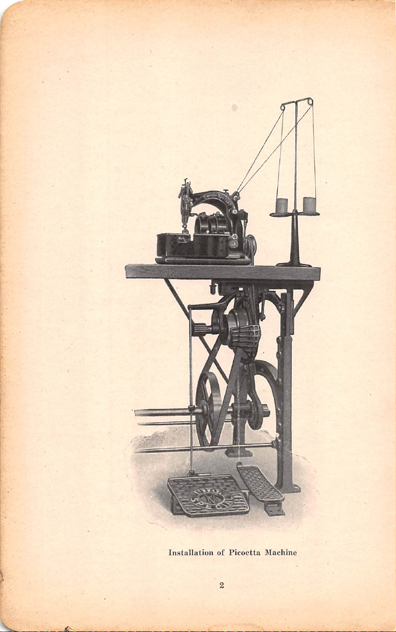
Installation
of
Picoetta
Machine
Page 3
Style
CLASS
G79000
G79000—PICOETTA
A
For
joining
effect,
left
needle.
makes 3 stitches
and
two
pieces
repeats,
MACHINES
to
plain
of
fabric;
fagotting
right, 3 stitches
feed
both
sides
to
of
Style
Style
Style
Style
G79000B
G79000
G79000
G79000
When
and
similar
lineal
stitching
per
hour
For
C
For
D
For
E
For
picoetta
edging
articles,
per
is
easily
edging
dresses,
lace
effect,
to
left
and
edging
dresses,
lace
effect,
to
left
and
edging
arched
lace
stitches
left
of
needle.
edging
pointed
3
stitches
to
left
of
woven
lingerie
and
makes 3 stitches
repeats,
woven
lingerie
and
makes 4 stitches
repeats,
knitted
effect,
to
left
makes 4 stitches
and
knitted
lace
effect,
to
left
and
needle.
PRODUCTIONS
ladies'
the
machines
collars,
will
hour. A production
obtained.
fabrics;
similar
plain
feed
fabrics;
similar
plain
feed
and
other
handkerchiefs,
articles,
to
right, 3 stitches
to
left
of
handkerchiefs,
articles,
to
right, 4 stitches
to
left
of
elastic
to
repeats,
and
makes 3 stitches
cuffs,
complete
differential
other
repeats,
elastic
differential
brassieres,
50
of 3 dozen
to
to
55
handkerchiefs
pointed
needle.
arched
needle.
fabrics;
right,
feed
A
to
fabrics;
right,
feed
lingerie
yards
of
INSTALLING
READY
thoroughly
inspected.
machine.
tion
The
tion.
TO
OPERATE
run
This
Packed
ready
for
service.
illustration
in,
accurately
is
evidenced
by
skilled
on
page 2 shows
Before
adjusted,
by
hands,
shipment,
tested
the
test
sample
they
arrive
the
general
each
and
at
plan
machine
carefully
left
their
destina
of
installa
in
is
the
Page 4
Style
G79000
Style
G79000
A
B
Style
G79000
Style
G79000
Style
G79000
E
C
D
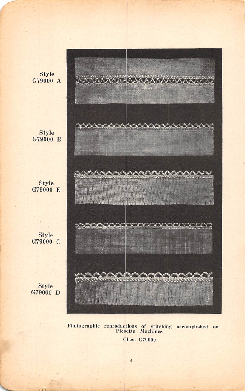
Photographic
U'
• •- 'J
5*^, i r f I'i--'jif
reproductions
Picoetta
Class
of
Machines
G79000
'
slEti
stitching
accomplished
4
if
]
i
on
Page 5
TREADLES
ter
is
directly
The
treadle
of
the
transmitter
Installing
The
transmitter
under
for
the
needle.
lifting
treadle.
the
(Cont'd)
treadle
presser
is
foot
so
located
is
located
that
its
to
the
cen
right
PULLEYS
line
shaft,
11, 12,
BELTS
means
shaft
The
from
SPEED
stitches
STARTING
machine
direction
turns
OILING
quently
will
systematic
should
Illustration
contain
against
ing
is
four
main
about
cup
required
to
belts
the
freely.
not
The
left
rod
Frequent
recommended
times a day.
The
shaft
once a week.
should
The
and
13,
14
The
of a round
the
must
operator.
The
per
minute,
THE
before
the
High
with
gum
way
be
taken
"A,"
end
ball
oilers.
the
ball
bearings
oiling
transmitter
from a compression
be
oftener
split
are
and
pulleys
furnished
15
inches.
transmission of
belt
9/32
inch
transmitter
be
placed
machine
MACHINE
starting
machine
If
this
speed
an
oil
which
or
become
every
that
Page
of
the
When
and
have
is
that
is
screwed
than
by
so
that
will
run
and
this
OPERATING
it.
runs a few
is
the
case,
machines
is
free
rancid.
day
before
all
the
oil
6.)
needle
lever
oiling
force
the
similar
necessary
the
machine
lubricated
If
the
up
immediately.
once a month.
are
generally
in
the
following
power
means
from
in
diameter
of a fl
the
top
at a maximum
speed
Then
oilers.
bearings
should
Thoroughly
turn
times
it
is
ready
must
be
from
rosin
The
oiling
starting
holes
are
supplied
is fitted
press
the
oil
in.
The
as
lint
quickly
be
given a thorough
with
solid
cup,
which
run
.
bored
for a ItVinch
sizes:
the
transmitter
and
from
at
belt 1 inch
of
the
hand
speed
not
be
exceeded.
clean
the
and
for
oiled
and
should
the
with
tip
of
needle
oil
should
hot,
Refilling
and
hand
wheel
see
that
sewing.
carefully
acid
be
machine
with
hollow
the
oil
lever
absorbs
through a hollow
be
the
compression
6,
8,
9,
is
the
line
wide.
wheel
pins
screwed
will
of
oil
in
machine
and
and
which
done
and
oil.
which
can
connect
the
not
runs
1500
fre
in
care
(See
spout
oil.
oiling
10.
by
the
the
a
It
up
be
CLEANING
the
aid
of a long
tion
of
lint,
easily
mended
removed.
to
remove
The
dust,
To
machine
handled
etc.,
in
thoroughly
the
cloth
should
paint
the
lower
plate.
be
or
vaniish
part
clean
cleaned
brush
of
the
the
machine
every
the
machine
day.
accumula
it
is
With
can
recom
be
Page 6
SETTING
are
designated
groove
needle
of
the
itself
is
into
the
The
of
the
eye
of
will
cause
THE
of
which
must
be
needle
size
thread,
the
is
in
line
needle
of
the
needle.
frequent
NEEDLE
Type
No.
the
longer
set
so
that
directly
with
the
bar
as
it
needle
that
is,
If
breakage.
Operating
The
needles
8021.
one
enters
the
long
in
front
stitching.
will
go,
and
must
be
the
thread
the
needle
(Cont'd)
for
They
are
the
groove,
of
the
Insert
tighten
in
proportion
must
pass
is
too
this
class
made
eye
of
the
which
operator,
the
needle
the
needle
to
freely
small
for
of
machine
with a double
needle.
enters
and
clamp
the
through
the
The
the
eye
the
eye
as
far
nut.
diameter
the
thread
up
it
f7
is
15 ' 15 a „
Illustration
"A"
shows
thread
adjacent
the
two
thence
needle
the
to
which
lever,
needle
the
are
"A"
the
"A"
passes
to
the
tension
through
thence
bar
and
needle
attached
01
Sehtyamm
correct
from
front
discs,
guide
to
over
bar,
thence
to
threading
tension,
thence
the
the
the
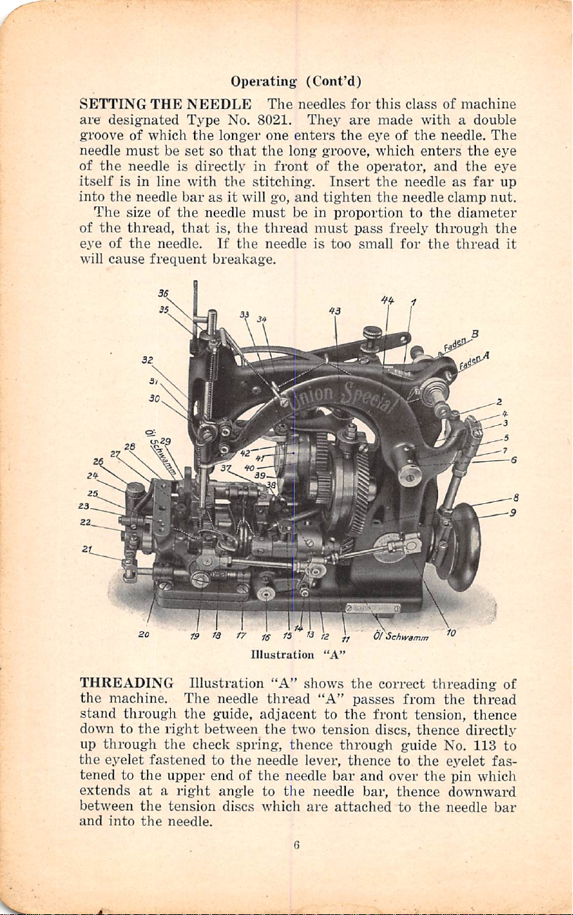
THREADING
the
machine.
stand
down
up
the
tened
extends
between
and
through
to
the
through
eyelet
fastened
to
the
at a right
the
into
the
»
fa
Illustration
The
needle
the
guide,
right
between
the
check
upper
tension
needle.
spring,
to
the
end
of
angle
discs
the
thread
thence
directly
No.
113
eyelet
needle
fas
pin
which
downward
of
to
bar
Page 7
The
looper
the
guide
sion
discs,
located
the
58,
No.
hang
in
guiding
thence
103
and
loosely
thread
adjacent
thence
the
through
rear
tube,
into
the
from
downward
of
thence
the
the
Operating
"B"
passes
to
the
rear
the
frame
between
two
looper.
end
(Cont'd)
from
tension,
through
at
the right
the
openings
Leave
of
the
about
looper.
the
the
of
two
the
thread
thence
guide
side,
springs
take-up
three
stand
between
No.
40
thence
Nos.
thread
inches
of
through
the
ten
which
is
through
57
and
eyelet
thread
IMPORTANT
properly,
lowing
Should
that
CAUTION
machine
a
few
machine
may
NEEDLE
then
its
bar
the
(use
When
needle
ment
eccentric
to
the
Again
reaches
yet
reasons
(1)
See
the
may
(2)
Examine
position
(3)
See
perfect.
(4)
If
(5)
See
needle.
(6)
Clean
the
some
always
times
until
result.
turn
farthest
to
its
lowest
point
looper
the
with a distance
is
accomplished
fork
desired
tura
its
HINTS
seems
may
if
the
different
have
the
and
if
the
the
needle
if
the
and
machine
part
of
the
Whenever
tuiii
to
make
this
AND
LOOPER
hand
wheel
position
point
of
looper
adjusting
looper
No.
position.
the
machine
lowest
Should
to
be
in
good
be
the
cause:
machine
tension
accumulated
needle
properly
needle
is
thread
oil
the
still
is
devices
and
is
perfectly
damaged
passes
machine
fail
to
machine
ADJUSTING
any
changes
the
hand
sure
there
test
has
been
Insert a new
in
operative
to
the
right
of
travel.
to
the
center
gauge
moves
79090,
point
to
of
.005
by
loosening
after
in
of
No.
the
inch
operative
travel
the
machine
condition,
threaded
and
between
see
if
seated
needs
in
straight
or
bent
freely
carefully.
operate
adjusting.
have
wheel
in
is
no
made,
direction
which
At
this
of
needle
21225-'i4)-
left,
its
between
the
which
the
direction
and
farthest
fail
any
one
correctly,
remove
the
it
is
the
install a new
through
properly,
the
bind.
as
needle
also
time
all
tension
set
in
needle
and
if
the
it
been
made
operative
Do
otherwise,
in
until
looper
brings
the
distance
should
point
should
them.
set
screws
looper
can
until
position
to
function
of
the
fol
especially
lint
discs.
the
bar.
the
eye
is
probable
direction
not
needle
the
be
pass
This
in
be
the
at
which
correct
point
needle.
of
the
in
the
run
the
damage
bar,
reaches
needle
from
inch
the
adjust
looper
moved
needle
to
the
is
Page 8
left.
As
moves
the
upper
the
to
left,
edge
needle
the
point
of
eye
moves
Adjusting
upwardly
of
the
looper
in
needle.
(Cont'd)
from
should
this
point,
pass
and
1/64
inch
looper
above
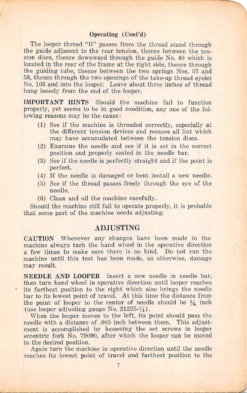
LOOP
universally.
thread
the
point
looper
moves
the
as
The
past
hook
the
CAST
so
No.
the
ery
and
until
thread.
the
its
RETAINER
until
looper
During
of
the
without
backward,
upper
near
as
loop
retainer
the
looper,
is
loop
retainer
OFF
that
it
79023.
rear
prong
of
the
move
the
take-up
Care
thread
Springs
forward
Its
the
as
it
moves
the
forward
loop
touching
edge
of
possible
inch
(see
WIRE
is
The
retains
cam
forward
should
passes
Nos.
motion
The
function
point
of
to
the
motion
retainer
it
the
loop
the
looper,
to
the
must
be
the
distance
Figure
does
not
The
inch
from
upper
57
portion
the
recedes,
to
the
has
completed
be
taken
are
smoothly
and
58
to
the
loop
retainer
is
to
retain
the
descending
right.
of
Fig.
1
must
pass
at
any
retainer
and
the
back
of
set
so
that
from
the
1).
Care
contact
lower
portion
the
bottom
No.
thread
when
front
prong,
to
should
left,
but
the
its
see
polished,
be
No.
79011
the
loop
needle
The
adjustment
the
looper
close
to
point.
starts
the
the
79004 A should
to
cycle
must
point
looper
when
center
should
looper
No.
of
the
the
point
thread
which
that
open
while
be
As
on
of
and
the
especially
passes
(to
the
upper
soon
its
the
without
the
needle
of
the
be
taken
at
any
79004
slot
where
must
retains
releases
points
the
closed
is
adjustable
of
the
back
is
as
follows:
the
left)
edge
as
the
way
back
hook
must
contacting.
descends
needle
to
see
point.
should
of
the
be
set
the
become
the
the
over
the
take-up.
looper
as
soon
needle
of
the
of
the
looper
over
pass
to
the
that
be
set
take-up
so
that
periph
free
thread
lower
which
makes
as
it
Page 9
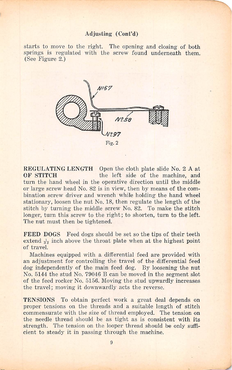
Adjusting
(Cont'd)
starts
springs
(See
to
move
is
regulated
Figure
REGULATING
OF
STITCH
turn
the
hand
or
large
screw
bination
stationary,
stitch
longer,
The
by
nut
screw
loosen
turning
turn
must
to
2.)
LENGTH
wheel
head
driver
this
then
the
with
in
No.
and
the
nut
the
middle
screw
be
tightened.
right.
the
A/iS7
m97
Open
the
the
operative
82
is
in
wrench
No.
18,
screw
to
the
right;
The
screw
A/^sa
the
left
view,
while
then
opening
found
clotli
plate
side
of
direction
then
by
holding
regulate
No.
82.
to
shorten,
and
closing
underneath
slide
No. 2 A
the
machine,
until
the
means
To
the
the
make
turn
of
hand
length
to
of
the
the
the
both
them.
at
and
middle
com
wheel
of
the
stitch
left.
FEED
extend
of
an
dog
No.
of
the
TENSIONS
proper
commensurate
the
strength.
cient
DOGS
i^ch
travel.
Machines
adjustment
equipped
independently
5144
the
stud
the
feed
rocker
travel;
moving
To
tensions
needle
thread
The
to
steady
Feed
dogs
above
the
with a differential
for
controlling
of
the
No.
79046 B can
No.
it
downwardly
obtain
on
the
with
the
should
tension
it
in
passing
should
throat
main
5156.
Moving
perfect
threads
size
of
be
on
the
be
set
so
plate
when
feed
the
travel
feed
be
acts
dog.
moved
the
the
of
stud
work a great
and a suitable
thread
as
looper
through
employed.
tight
thread
the
as
the
tips
of
at
the
are
provided
the
differential
By
loosening
in
the
upwardly
reverse.
deal
length
The
is
consistent
should
machine.
their
highest
segment
increases
depends
of
tension
be
only
teeth
point
with
feed
the
stitch
with
suffi
nut
slot
on
on
its
Page 10
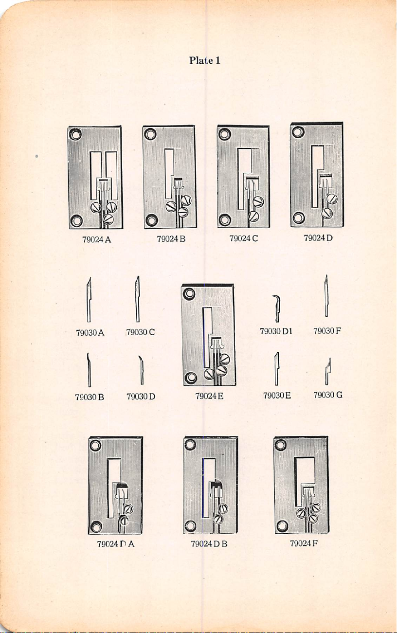
Plate
1
79024
79030A
79030B
D1
©
79024D
79030F
79030G
©
A
79030C
79030D
79024B
79024E
79024C
79030
79030E
iJL
79024 r A
79024 D B
79024F
Page 11
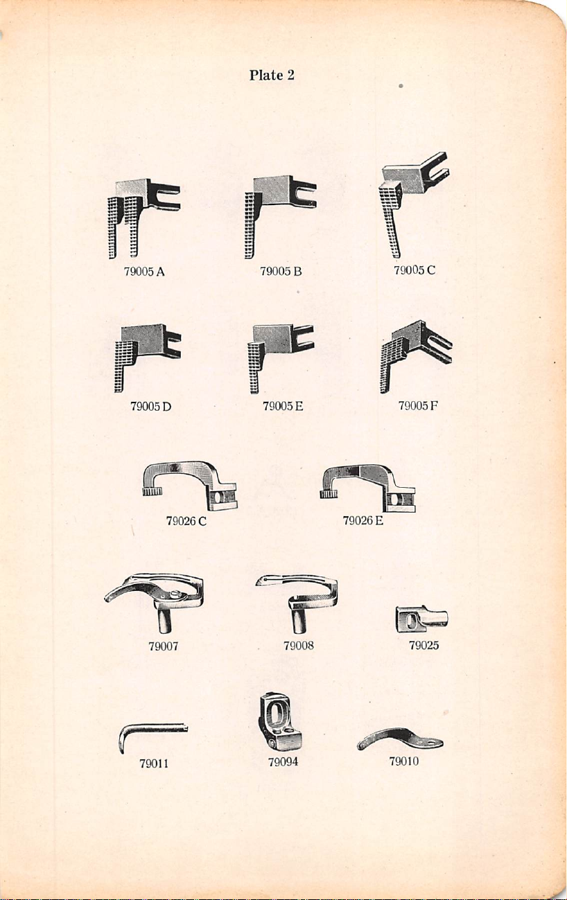
Plate
2
79005
79005D
A
79007
79026C
79005
79005E
79008
B
79026E
79005C
79005F
79025
79011
79094
79010
Page 12
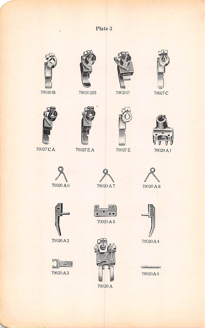
79020B
79020
BB
Plate
3
79020F
V®/
79027C
79027CA
79020 A 6
79020A
79020A3
2
79027EA
79020 A 7
00
79020A
79020
A
79027
5
E
79020
79020
A8
A1
I
79020A4
79020A9
Page 13
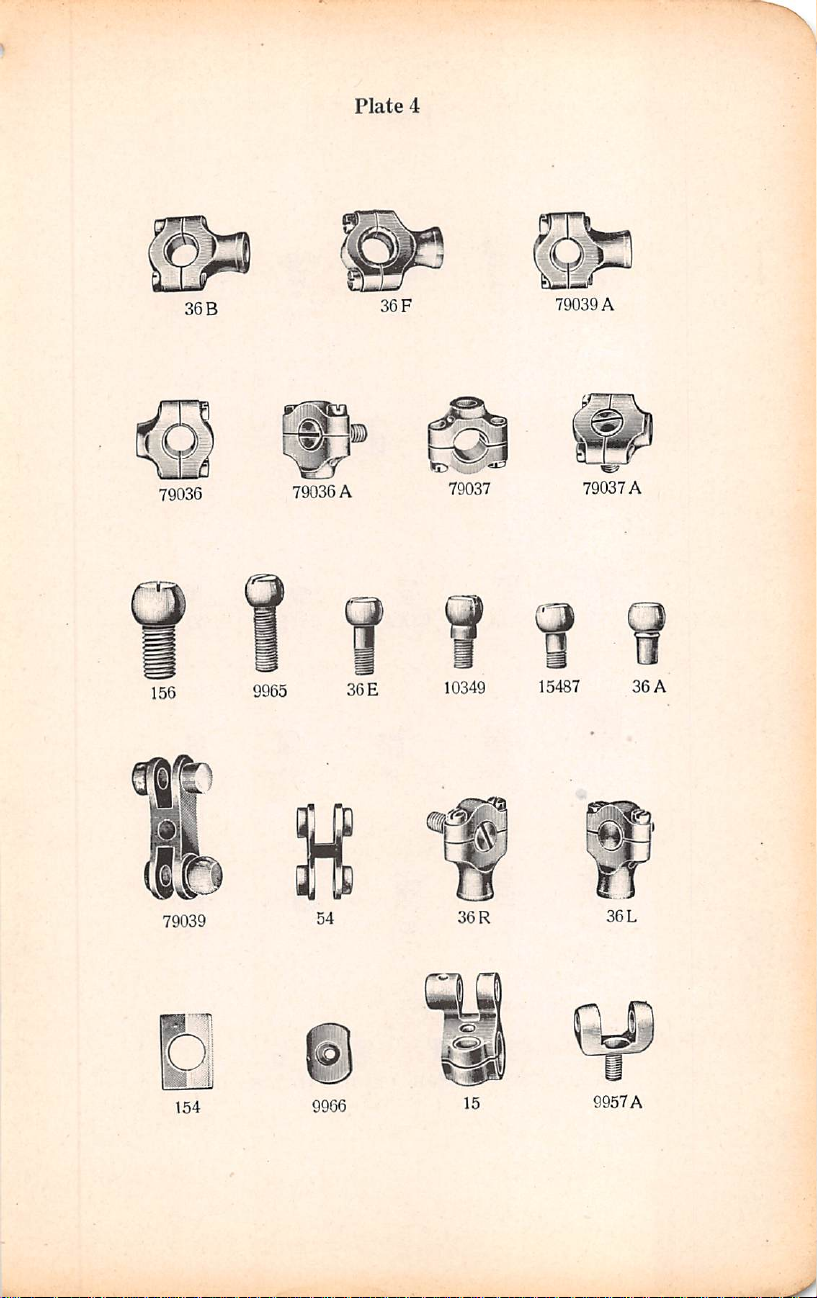
36
B
79036 79036
A
Plate
36
4
79039
F
79037
A
79037
A
Q
156
9^
79039
D
154
9965
54
9966
36E
10349
36
R
15
15487
36
9957A
36
L
A
Page 14
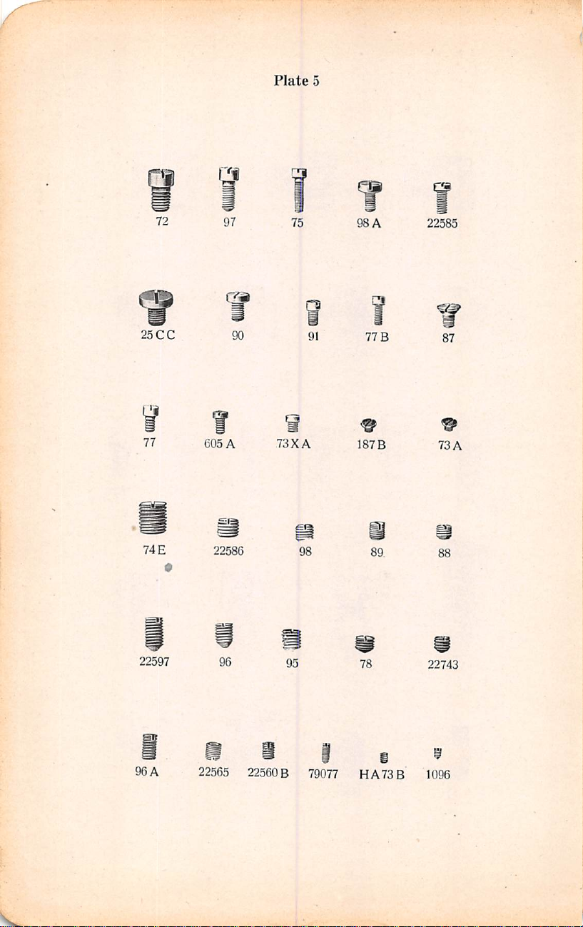
Plate
5
25
77
74
72
CC
E
97
cm
e05A
22586
90
75
73XA
98
91
98
A
77
B
1873
89
22585
87
73A
88
22597
96A
96
22565
95
22560 B 79077
78
HA73B
22743
1096
Page 15

Plate
6
tMWttWU
64A
22587
92124
17
85
A
a
6042
75A
135
22814
5!
82
22574
85
22596
25
TB
r
97
93
94
A
A
79
303
25CD
80
86
134
22548
15438
22730
D
93
79048
22539
Page 16

Plate
7
79049
258
15430C
1346
47
18
15430D
5144
T1
34
1280
nr
1347
15037
A
37
107
7947
L
5G
37
2)212
108
7948
R
79031
48
i{0«
15488
36
G
129
20
22586 A 22702
64
B
Page 17

113
79004
57
.2)
J
Plates
103
79004A
58
F
w
79059
16
52
A
sdtrqM
15438J
m
79059B
40
109
12534
19
W
15438B
104
'
41
A
79057
Page 18

Plate
9
111
2U
EZZG
I
HA
42D
1362
1286
A
1362
79041-1
15437A
79074
!
9957
1286
1230D
15438H
B
79046 B HS65P-4
426A
41046G
79051-1
84
a
79086
A
1361A
21
12964C
1349
Spfcirr
OF
A
DiAMtWR
NNtRe
79085
1230B
42C
15438C
15452
Page 19

Plate
79093
10
79003D
79079
A
, . 5 si
X.
70
Jl-*
A
79092
6B
lOA
M
61B
70
79003E
9962
79002
B
B
79003C
79003F
Page 20

Plate
11
fjwiwj
79081
7907&
9961
B
7904G
79079
75240
O
79046A
HA66K
43
79055
79013
HS
10314
33
K
I
128D
79068
_
79043
1
79023
Page 21

@3
79045
Plate
12
5156
79072
79041
79047
79060
5'
79073
79075B
A
79071A
79054
79012
Page 22

Plate
13
32
14544
4973
B
79040
1275
79058A
79056
31
79076
A
79035
C
122
s
A
62
B
79035B
a
10356
79060 A 4517
60
3
79022
Page 23

79062
79063
A
Plate
14
A
79063C
^0
79062C
9943
B
79064
79061
A
79064
79061C
A
Page 24

1.
Plate
15
B
79042
79051
1221
79002
79091
79042
A
A
79090
63B
79052
79002
Page 25

1216C
1230
Plate
16
79001
1230
G
C
79015
79044
1230
A
Page 26

Plate
17
2138SB
21681
116
21388
"
f/
118B
79050
21206
6
529
NT8A
NTS
I
G
105
A
69AP
413
99163
Page 27

21662
Plate
18
21665
21687
69FD
99162
99163
21677B
21679
Page 28

Plate
19
79084
79080
79na3
Page 29

LIST
OF
PARTS
Symbol
to
NTS
NTS
Order
A1
2
2
6
6
8
8-408
8-410
8^13
8-416
8-419
8-422
10
15
16
17
18
19
20
21
25
25
25
31
31-40S
31-410
31-413
31-416
31-419
31^22
32
32^08
32-410
C
A
U
A
CC
CD
The figures
by
parts
Main
Cloth
Cloth
Looper
Feed
Feed
Feed
Feed
Feed
Feed
Feed
Screw
A
Screw
Feed
Feed
Feed
Feed
Feed
Feed
Feed
Feed
Screw,
Screw,
TB
Thumbscrew,
Looper
Looper
Looper
Looper
Looper
Looper
Looper
Looper
Looper
Looper
in
and
are
Shaft
Plate
Plate
Eccentric
No.
94)
Rocker
standard
Rocker
Rocker
Rocker
Rocker
Rocker
Rocker
Driver,
Driver,
Bar
Prong
Crank
long,
No.
No.
79,
Crank
Crank
Crank
Crank
Crank
Crank
No.
77)
for
for
G79000
Rock
standard
Rock
Rock
Rock
Rock
Rock
Rock
Rock
standard
Rock
Rock
the
last
column
not
to
be
used
Renewable
Slide,
left
Hinged
Cover
Fork
Shaft,
S-fg
diameter
Link,
22569,
obsolete)
Link
Stud
Stud
Stud
Stud
cloth
cloth
A
diameter
diameter
.407
Shaft,
standard
Shaft,
standard
Shaft,
standard
Shaft,
standard
Shaft,
standard
Shaft,
standard
large
small
Sponge
hardened
lock
Ferrule,
Nut;
Cap
Washer
Link
Pin,
plate
plate
for
cloth
Shaft,
3j
.407
Shaft,
standard
Shaft,
standard
Shaft,
standard
Shaft,
standard
Shaft,
standard
Shaft,
standard
Shaft,
ij
.407
Shaft,
standard
Shaft,
.standard
guides
refer
only
in
ordering,
Bearing,
Shoe,
inches
right,
Latch
hardened
long,
inch
(screw
diameter
diameter
diameter
diameter
diameter
diameter
(shim
nut
No.
7947,
hardened
also
for
Nos.
(screws
No.
hardened
hinged
cover
Nos.
plate
slide
inches
long,
inch
diameter
diameter
diameter
diameter
diameter
diameter
inches
long,
inch
diameter
diameter
to
the
plates
Refer
to
pint-
2y|
inches
No.
and
ground
hardened
plus
.001
plus
.003
plus
.006
plus
.009
plus
.012
plus
.015
No.
1248,
screw
screw ^ inch
and
ground
36
E,
128
77)
and
ground
79003
C,
79003
No.
79002,
hardened
plus
.001
plus
.003
plus
.006
plus
.009
plus
.012
plus
.015
hardened
plus
.001
plus
.003
illustrating
insert
for
the
prices.
long....
134)
(screw
and
ground,
inch.
...
inch. ...
inch. ..
.
inch.
...
inch. ..
.
inch....
inch
long,
D,
128
D-1
(set
screw
!
F
on
Style
and
ground,
inch....
inch....
inch.
...
inch.
...
inch.
...
inch...
and
ground,
inch....
inch....
Plate
No.
15
9
10
13
—
—
—
—
—
—
17
17
10
4
8
6
7
8
7
9
5
6
6
13
—
—
—
—
—
—
.
13
—
29
Page 30

LIST
OF
PARTS
Symbol
to
Order
32-413
32-416
32-419
32-422
33
HS33
34
36
36
36
36
36
36
36
37
37
40
41
41
42
42
43
47
48
52
54
56
57
58
60
60
60
60
60
60
61
by
K
A
B
E
F
G
L
R
L
R
A
F
C
D
A
B
B-322
B-325
B-328
B-331
B-334
B
The figures
parts
and
arc
Looper
Rock
Looper
Rock
Looper
Rock
Looper
Rock
Looper
Rocker
Woodruff
Looper
Rocker
Looper
Connecting
Looper
Looper
Looper
Looper
Looper
Looper
Looper
Looper
Frame
Hand
Lifter
Lifter
Lifter
Feed
Needle
Needle
Needle
Needle
Needle
Looper
Looper
Presser
Presser
Presser
Presser
Presser
Presser
Presser
Connecting
No.
97
Connecting
Connecting
No.
97
Connecting
Connecting
No.
97
Connecting
No.
97
Connecting
Connecting
Looper
Lifter,
Lever
Lever
Lever
Lift
No.
96)
Lever
Lever
Lever
Lever
Clamp
Thread
Thread
ating
screw
Bar,
.319
inch
Bar,
Bar,
Bar,
Bar,
Bar,
Bar
No.
97)
in
the
last
column
not
to
be
used
Shaft,
Shaft,
Shaft,
Shaft,
Stud,
Key,
for
looper
Stud
A)
A)
A)
Rod
A)
Thread
hardened
(stud
No.
Spring
Spring
Eccentric,
Stud
Stud
Thread
Link,
Nut,
Nipper
Nipper
No.
97)
hardened
standard
standard
standard
.standard
standard
Connection
refer
only
in
ordering.
standard
standard
standard
standard
-jV
diameter
diameter
diameter
diameter
inch
diameter
compensating
Nut
Rod
Ball
Stud,
Rod
Ball
Rod
Ball
Ball
Ball
Ball
Ball
Joint
Nut,
Nut,
Stud,
Joint
Joint
left
right
Rod
Rod
Rod
Rod
Rod
Guide,
(stud
No.
92124)
Pin
ground,
Nut,
hardened
Washer
Eyelet
(screw
hardened;
also
hardened
Spring,
Spring,
and
ground,
diameter
diameter
diameter
diameter
diameter
(screw,
to
the
Refer
left
Joint
right
Joint
Shell,
Wa.sher
Assembly,
Assembly,
thread
thread
lower,
right
86)
throw
No.
for
upper
(screw
lower
(screw
plus
.003
plus
.006
plus
.009
plus
.012
plus
.015
front,
plates
illustrating
to
pink
insert
plus
.006
plus
.009
plus
.012
plus
.015
horizontal
Shell,
left
(nut
No.
right
left
right
.062
inch
98
A)
Nos.
79052,
No.
No.
standard
inch
inch
inch
inch
inch
No.
89,
screw,
the
for
prices.
inch.
...
inch....
inch.
...
inch....
shaft..
(screws
18)...
.
(screws
(screws
(screws
(screw
79054.
.
90)
90,
oper
diameter
rear,
Plate
No.
11
16
11
13
10
6
7
4
4
4
4
7
9
9
7
7
8
4
7
30
Page 31

LIST
OF
PARTS
^mbol
to
HS65
HA66
72
73
73
HA73
74
75
75
77
77
78
79
80
82
84
85
85
86
86
87
88
Order
62
B
62
B-322
62
B-325
62
B-328
62
B-33I
62
B-334
63
B
64
A
64
B
P-4
K
68
B
69
AP
69
AW
69
ES
69
FD
70
70
A
A
XA
B
E
A
B
A
A
A
The figures
by
parts
Presser
eter
Presser
Presser
Presser
Presser
Presser
Presser
Presser
Pre.sser
Needle
Woodruff
Main
Thread
Spool
Thread
Set
thread.s
for
Looper
No.
Looper
Set
Screw,
Set
Set
Set
Screw,
Screw,
crank
Screw,
HA1286,
Screw,
Set
79073,
Screw, ^ inch
Screw,
Screw,
Stitch
Clamp
Clamp
Hand
Hand
Screw,
Set
79046,
in
the
and
are
not
Guide
.319
inch
Guirle
Guide
Guide
Guide
Guide
Spring
Spring
Spring
Thread
Key,
Shaft
Sleeve,
Stand
Support
Stand
Screw,
square
to
Nos.
21665,
Eccentric
93
A)
Eccentric
Screw,
for
for
looper
Screw,
for
Screw,
for
Screw,
for
for
looper
front,
connection
for
feed
1286
for
presser
Screw,
for
79073
inch
for
regulating
Regulating
Screw,
Screw,
Lifter
Stud
Lifter
Stud,
for
throat
Screw,
for
79047,
last
column
to
be
Bar,
Bar.
Bar,
Bar,
Bar,
Bar,
refer
used
in
ordering.
hardened
standard
standard
standard
standard
standard
Regulating
Regulating
Tension
for
Wire
for
Base
inch, | inch
Take-up
looper
compensating
1^
inches
thread
stands
head,
cup
long,
21677
B,
Sponge
Sponge
looper
eccentric
needle
guard
looper
presser
foot
looper
compensating
compensating
inch
long,
crank
stud
A,
79004,
foot
l)racket
upper
needle
A
long,
for
feed
long
for
cloth
length
Ferrule,
for
looper
for
needle
eccentric
loop
retainer
plus
size
pktes;
also
bar;
also
79092
only
to
Befer
and
ground,
diameter
diameter
diameter
diameter
diameter
Screw
Screw
Look
Spring
long...,
point,
for
thread
21679
Holder
fork
springs
cam
cam
for
loop
cap;
also
79004
A,
lever
link
crank
link,
plates
of
stitch
inch
long
fork
rocker
threads,
for
Nos.
for
Nos.
the
plates
to
pink
standard
plus
.003
jiltis
.006
plus
.009
plus
.012
plus
.015
Nut,
Stud...
vertical
inch
stand
and
Sponge
shaft
gear
pinions
retainer
for
Nos.
79011
pin;
obsolete
tap
No.
62
B,
5156,
9961B,
illustratirg
insert
for
the
prices.
diam
inch
inch
inch
inch
inch
knurled
.
shaft
diameter,
18
seat;
also
(screw
!
shaft
bell
21,
122,
also
for
Nos.
V113
129
79012,
No.
13
15
6
7
9
11
11
17
17
17
18
10
10
5
5
5
5
'
5
5
- 6
5
5
5
6
6
6
9
6
6
6
—
5
5
31
Page 32

LIST
OF
PARTS
•
to
0105
VI09
Symbol
Order
89
90
91
93
93
94
95
96
96
97
97
98
98
103
104
107
108
109
111
113
VI13
116
IIS
VI
IS
122
127
128
128
128
128
129
The figures
parts
by
Screw,
Screw,
Clamp
Screw,
A
Screw,
Screw,
Screw,
Screw,
A
Set
Screw,
A
Screw,
Screw,
A
F
Screw,
Looper
Looper
A
Stove
Tension
Ten.sion
Tension
Tap,
Tension
Frame
Tap,
Wrench, ^ inch,
U
Threa<l
Tap,
Pivot
D
D-1
D-2
D-3
and
front,
for
79059
Screw,
Nos.
113,
79079,
79054
for
79022,
79043
Screw,
Nos.
Nos.
Nos.
79037
Bolt,
m.arked
93
A')
marked
marked
Pin,
bar
.swinging
Needle
Cam
Roller
Cam
Roller
Cam
Roller,
Cam
Roller
Prcs.scr
in
the
last
not
to
for
79074
for
looper
column
be
used
presser
thread
pre.sscr
thread
are
looper
B,
for
79044, 79078,
for
looper
eccentric
79079
for
looper
eccentric
needle
79053,
feed
lift
79068
for
needle
A,
operating
B,
103
lower
B,
36
79039
tension
needle
Take-up
Take-up
for
fastening
Ferrule
bar
79063
F,
bell
F,
A,
thread
lever
79031,
for
79063
for
61
for
36
A,
for
for
Thread
Thread
Spring
Regulating
Disc,
hardened
"J2",
Thread
Eyelet,
Thread
Guide,
"Q2",
for
Tweezers
"X2",
I5
inches
frame
Bar
Oscillating
Assembly
Stud,
hardened
hardened
Stud
Guide
Holder
Bar
refer
in
ordering.
bar
connection;
nipper
feet
take-up
79079,
79079
sponge
A,
79081,
fork
oscillating
79071
eccentric;
bar
oscillating
B,
79063
looper
thread
79012,
79046
crank
eccentric
36
L,
36
79042,
79042
evelet;
thread
Eyelet
Eyelet
base
Nut,
knurled
and
for
No.
22526
with
attaches
for
No.
needle
for
No.
long,
hardened
bell
crank
Cam
fctamp
and
ground
Cap
(screw
only
to
the
Refer
to
springs;
also
eyelet
A,
79094
holder;
79083
shoe;
cam
pinions;
A
also
for
Nos.
cam
C,
79063
nipper
A,
79046
connection;
R,
79036,
A
also
for
eyelet;
also
(adjusting
Spring
plate
to
lapped
two
eyes
to
top
86
.V
clamp
nut
22521
and
(set
Wa.sher
screw
ground
No.
screw
No.
87)
Stud
and
plates,
illustrating
pink
insert
also
for
No.
for
Nos.
spring;
also
also
for
Nos.
also
10314, 79012,
shaft;
D
.springs;
B
79036
A,
Nos.
9271,
for
No.
screw
No.
(screw
No.
table
(screw
No.
of
arm
(screw
grovmd,
No.
136)
(nut
No.
for
79023
79059,
also
for
for
also
also
also
79037,
79012.
9966..
93)..
98)....
for
77)
18)....
the
pnces.
for
Nos.
132,
Nos.
for
for
for
97).
.
..
No.
needle
Plate
No.
5
5
◦
6
6
6
5
5
6
5
6
5
5
s
8
IV
V
V
8
—
9
8
—
IV
17
—
13
7
11
—
—
—
V
32
Page 33

LIST
OF
PARTS
^mbol
to
Order
132
. 134
136
154
156
187
258
303
413
426
Y502-319
Y502-322
Y502-325
Y502-328
Y502-331
Y505-407
Y505-410
Y505-413
Y505-416
Y505-419
Y506-530
Y506-533
529
605
Y800
Y801
Y802
1096
1216
1221
1230
1230
1230
1230
The figures
by
parts
Needle
Screw,
Clamp
Needle
Needle
B
Screw,
Loop
Adjusting
Oil
A
Lifter
Expansion
Expansion
Expansion
Expansion
Expansion
Expansion
Expansion
Expansion
Expansion
Expansion
Expansion
Expansion
A
Thread
Screw,
Taper
Taper
Taper
Stop
C
Needle
Eccentric
A
B
C
D
Needle
Needle
Needle
Needle
(screw
and
are
Bar
for
Screw,
for
No.
Lever
Lever
for
Retainer
No.
9965
Can,
Lever
bars,
size
Hook
for
Reamer,
Reamer,
Reamer,
link
pins
Screw,
Lever
feed
oiling;
1230
D,
No.
41046
Lever
No.
22587)
Lever
Spring
Lever
left
thread
Lever
in
the
last
not
to
be
Swinging
clotli
plate
79065
Buffer,
Ball
throat
Shaft
Screw,
with
spout
Spring
Reamer,
.319
Reamer,
Reamer,
Reamer,
Reamer,
Reamer,
Reamer,
Reamer,
Reamer,
Reamer,
Reamer,
Reamer,
needle
bar
for
for
for
for
cloth
Connecting
one
1230
G,
G
Pulley,
Connecting
Connecting
Connecting
No.
15430
Connecting
No.
22586
column
used
in
Frame
hinged
inch
long,
wood fibre
Stud,
plate
stitch
Knuckle
for
loop
Pin
for
size
size
size
size
for
feed
size
size
size
size
for
size
thread
lever
frame
needle
plate
each
15430
throw
C,
refer
only
ordering.
Brace
cover
for
hardened
tongues.
Link
retainer
prcsser
.322
inch
.325
inch
.328
inch
.331
inch
rocker
.410
inch...
.413
inch.
.416
inch
.419
inch.
main
shafts
.533
inch
evelet
end
of
needle
end
of
lever
slide
Rod
Assembly,
No.s.
1230
C,
15430
.529
inch
Rod
Rod
Rod
Tube,
nut,
right
Rod
to
the
plates
Refer
to
(screw
latch
cam
roller
.
Lock
shaft
bars
and
shafts,
..
,
..
size
,530
lever
needle
lever
link
pins
No.
79002
A,
1230
D,
22586 A and
(screws
Upper
Upper
includes
thread,
Upper
illustratirg
pink
insert
fcr
No.
94).
assembly;
Nut;
also
knuckle
link..
presser
size
.407
inch
stud
.stud.
and
feed
wick
and
B,
1230
No.
22597).
Bearing
(screws
Bearing
felt
No.
15430
Bearing
the
prices.
. .
also
for
..
guide
inch..
crank
splash
C,
two
...
Valve
(nut
D)
Valve
No.
10
6
6
4
4
5
7
6
17
9
_
17
5
—
5
16
15
16
9
16
9
33
Page 34

LIST
OF
PARTS
to
1230
1248
1275
1275
1275
1275
1275
1280
1286
1286
1288
HA1286
1346
1347
Symbol
Order
G
A
E
.1
1349
1349
1361
by
F
H
A
B
A-2
A^
A
The figures
parts
Needle
Feed
Needle
Needle
Needle
Needle
in
the
and
arc
not
to
Lever
Connecting
splash
feed
oiling
Crank
Link
Lever
Stud,
Lover
Stud,
.002,
.003,
Example;
on
frame
.002,
1275
section
.006, .012,
1275
section
Lever
Stud,
.003,
.006
F-003
Lever
Stud,
last
represents a stud
.001, .002, .003,
ample:
each
Needle
(.001,
(.002,
(.006,
(.012,
(.018,
Specify
lever
stud
section,
on
screw
Needle
Needle
and
Needle
screw,
Needle
Looper
Tension
for
Tension
Tension
Tension
Presser
1275
section.
Lever
Stud,
.002)
.003)
.001)
.003)
.006)
plus
section
plus
.003
1275
frame
section
No.
22586,
Lever
Ball
Lever
Link
ground
Lever
lower
Lever
Link
Compensating
Assembly
Post,
use
with
Post
(set
for
Ferrule,
Spring,
Spring,
Spring
(.001,
(.002,
(.006,
(.012,
amounts,
la.st.
column
used
in
refer
ordering.
be
Rod
(screws
Shim,
standard
leather
plus
size
No.
.018
E-003
represents
plus
size
inch;
specify
plus
size
.006
H-003
inch;
represents
plus
size
.003)
(.001,
.006)
,002)
.006)
arranged
Example:
inch
enframe
J-006-003
Link
No.
represents a stud
and
.003
felt)
Stud
Clamp
Pin
.\s.sembly,
Pin
(set
77)
Pin
Spring
Horizontal
screw
No.
looper
hardened
.025
.035
Pin
77)
thread,
.steel
hardened
inch
diameter
inch
diameter
only
to
the
Refer
Lower
22587)
diameter
on
frame
inch;
specify
a
on
lever
plus
amount.
plus
equal
on
specify
a
.stud
unequal
on
.006)
(.003,
.002)
(.006,
.003)
(.018,
.001)
frame
1275
J-003-006
section
and
inch
on
Bolt
Nut
internal
screw,
Shaft
length
ferrule
wire,
wire,
plates
illustrating
to
pink
insert
for
Bearing,
section,
stud
section,
wick
viz.:
phis
amount.
plus
.003
viz.:
Example:
.003
inch
on
each
section,
plus
amount.
plus
.003
each
section,
(.002,
.001)
(.003,
.006)
(.012,
.002)
(.018,
.002)
section first
represents
.006
inch
plus
.006
lever
section
oiling,
hardened
upper
No.
Arm
Link
overall
1^
for
looper
for
needle
the
prices.
and
.001,
inch
•
•
.001,
lever
viz.:
Ex
inch
on
viz.:
and
a
on
lever
inch
(plug
78,
set
Pin
inches,
thread
thread
Plate
No.
16
13
34
Page 35

LIST
OF
PARTS
Symbol
to
Order
1362
1362
4517
4973
5144
5156
6042
7947
7948
9271
9943
9943
9957
9957
9961
9962
9965
9966
10314
10349
10356
12534
12964
14544
15037
15430
1.5430
15430
15437
15438
15438
15438
15438
15438
15452
15487
The
figures
in
the
last
coluinn
refer
only
to
the
plates
parts
and
are
not
to
be
used
in
Pin, right
Pin,
left
No.
Cam
Bar
Link
No.
Stud
Nut;
also
Horizontal
(screw
Cam
Knuckle
Knuckle
Crank
Knuckle
258)
Crank
Crank
ground
Horizontal
Rod,
R,
nut,
Eyelet
Pin
Ball
Vertical
No.
22587)
Horizontal
Vertical
ordering.
and
Clamp
left
and
Thread
Thread
Thread
Thread
by
Main
Shaft
Sleeve
Main
Shaft
A
Needle
.200
B
Needle
Differential
Feed
Needle
Feed
Looper
Nut,
Knee
B
Needle
No.
E
A
B
B
B
Needle
Loop
Loop
Loop
Loop
303,
Loop
Loop
98
Looper
Looper
Looper
thread
Needle
C
A
C
D
M
Needle
Feed
Looper
Needle
Needle
Needle
oiling
A
B
C
D
H
J
Needle
Needle
Needle
Needle
Needle
Needle
Looper
Pin
Looper
No.
Sleeve
Bar,
hardened
inch
(set
Bar
Rocker
Lever
Crank
screws
Oscillating
Feed
(screws
Ball
Link
Compensating
left
thread
Press
Collar
Bar
O.scillating
95)...'
Bar
Oscillating
Retainer
Retainer
Retainer
Retainer
lock
Retainer
Retainer
A)
nut
Shaft
Shaft
Bell
Shaft
No.
Bell
Bell
Eccentric,
Compensating
Connecting
No.
37
Bar
Thread
Lever
Link
Bar
Shaft
Compensating
Lever
Connecting
Lever
Connecting
Lever
Connecting
(screws
Bar
Connection
Bar
Connection
Bar
Connection
Bar
Connection
Bar
Connection
Bar
Connection
Compensating
Spring
Compensating
15037
A)
ground,
88)
Shaft
Stud
88)
Bolt
for
No.
No.
98)
Cam
Pinion,
Pinion
Pin
Cone
(screws
Link
Ball
Stud
Ball
Stud
(screw
left,
3^
thread
(screw
Shaft
Rod
Nut,
Rod
Nut,
Rod
Lower
Thread
Nipper
Nipper
Nipper
Nipper
Shaft
Refer
(set
Nut
79035
Shaft
(screws
(adjusting
(lock
No.
Shaft
inches
No.
No.
left
right
Nipper
Rock
illustrating
to
pink
insert
standard
screw
No.
C
Connecting
obsolete
No.
No.
88)
nut
Washer
(screw
96)
Arm
Ball
long
(nut, right
37
L)
605
A)
Arm
Ball
thread
thread
Bearing,
Assembly
Disc
Spring
Stud
Guide
Shaft
Arm
Ball
for
diameter
96
A).
(screws
95)
screw
No.
258).
Stud..
Stud
wick
Arm
Stud
the
prices.
..
Rod
No.
.
No.
.
Nut.
feed
Link
(nut
Plate
No.
13
13
12
18
14
11
10
11
13
13
7
6
7
7
4
9
4
4
4
9
7
7
7
35
iMliii
>11
I'lll/'
inii'ii
I
Page 36

LIST
OF
PARTS
^mbol
to
Order
1.54SS
21206
21212
212252I26I
21262
21350
21351
21355
21355
21358
21371
21371
21371
21371
21371
21371
21371
21384
21388
21388
21394
21394
21394
21394
21662
21665
21677
21679
1
"4
A
B
M
T-2
T-^
T-6
T-8
T-16
A
B
G
H
K
B
The figures
parts
by
I.rf)oper
Screw
Fresser
Looper
Leather
Leather
Malleable
Wire
Chair
Chair
Main
Table
Individual
Individual
Individual
Individual
Individual
Individual
Leather
Wrench,
Wrench,
Small
Emery
Emerj'
Grinder,
Knee
Knee
Knee
Knee
in
tlic
lost
not
to
colunin
be
used
and
are
Compensating
Wa.=her
Driver
Wrench
Bar
Collar
.080
Adjusting
Belt,
malleable
Belt,
including
Belt
Leg
Leg
Shaft
Top,
thick
belting,
pulley
guard,
electric
fied
D.
C.
electric
single
phase,
single
phase,
three
pha.se,
Plug,
hardened,
hardened,
Utility
diameter, f inch
lutions
per
Gauge, 7 inch
flat, 1 inch
iron
belt
round, ^ inch
wire
l)elt
Iron
Belt
Hook,
for ^ inch
Extension, 4 inches
Extension, 6 inches
Lubricator
48
inches
Power
Table,
transmitter
Power
Table,
pitman,
motor.
Power
Table,
motor
Power
Table,
60
Power
Table,
60
Power
Table,
60
cycle,
for
cloth
Note:
cycle,
cycle,
for f inch
for h inch
Grinder,
face,
minute
Wheel, 5 inches
hole,
grade
M,
Wheel, 5 inche.s
grade
M,
including
face,
recommended
Press
Press
Press
Press
emerv
emery
60
emery
Bracket
Rod
Connection
Lever
(set
Rod
(set
refer
only
thick
to
Refer
Shaft
in
ordering.
Vertical
inch
measurement
wide,
63
fastener
No.
21350
diameter,
hook
No.
21351
Fastener,
for 1 inch flat
round
long
long
Felt
long,
I65
inches
excludes
and
electric
motor,
includes
belting, 5 H.
Style
of
machine
equipped
equipped
A.
C.
electric
with ^ H.
equipped
A.
0.
electric
equipped
A.
plate
C.
electric
screw
with ^ H.
hexagon
hexagon
including
emerj'
recommended
diameter, f inch
60
diameter, | inch
wheel, 5 inches
speed
3000
revolutions
(screws
screw
No.
No.
69
69
FD)
screw
the
plates
illustrating
to
pink
insert
Arm
Ball
inches
long,
including
44
inches
belt
belt
wide,
if
pulley
guard,
includes
transmitter,
P.
115
Volt,
must
be
with 5 H.
P.
P.
230
110
motor
with j H.
P.
220
motor
P.
220
motor
holes
nuts
nut.?
wheel, 5 inches
speed
3000
face, | inch
face, | inch
diameter, ^ inch
per
No.
69
FD)
FD)
the
for
prices.
Joint
long,
inches
pitman,
treadle
treadle,
D.
C.
.speci
Volt
Volt,
Volt,
Volt,
revo
hole,
minute.
Plate
No.
17
—
—
—
—
—
—
—
17
17
18
18
18
18
7
7
36
Page 37

LIST
OF
PARTS
Symbol
to
Order
21681
21687
22.521
22.526
22.53fl
22548
22.560
22.560
22.565
22.569
22574
2258.5
22.586
22586
22587
22596
22597
22702
22730
22743
22814
28606-f
28606-1
29066
29086
29086
29346
41046
75240
79001
79002
79002
79002
79002
The figures
by
parts
Thumbscrew,
Knee
Screw,
Screw,
Plug
Screw,
Screw,
B
Set
Set
Screw,
Screw,
Screw,
Plug
A
Screw,
Screw,
Screw,
Screw,
Screw,
Screw,
Set
Screw,
Powdered
Powdered
B
A
E
Needle
Eccentric
Eccentric
Needle
G
Spring
Main
Cloth
Cloth
A
B
C
Cloth
Cloth
Cloth
in
the
are
not
last
to
be
and
for
Press
Chain
plus
size,
plus
No.
.size,
V109
Screw, ^ inch
for
loop
for
Screw,
Screw,
ff
for
79026
Screw,
for
for
for
for
for
for
Screw,
one
1230 D and
Nos.
one
each
No.
41046
lapped
bearing
Shaft
Plate
Plate
No.
25
Plate
Plate
G79000
25
CC)
retainer
needle
for
needle
lower,
inch
long,
inch
long,
feed
bar
E
for
needle
needle
needle
looper
eccentric
cam
spring
fabric
for
differential
for
loo))er
Oil
Stone, i lb.
Oil
Stone, 1 lb.
Lever
Connecting
each
Nos.
22586
Pulley
1221
and
Pulley
Nos.
G
Lever
Assembly;
together,
Valve
Oiler,
No.
1230
Sleeve,
(screws
Slide,
TB,
stop
Hinged
Slide,
D,
G79000E
Plate
Hinged
column
refer
only
to
used
in
ordering.
fastening
for
cloth
plates,
machine
diameter ^ inch,
long,
for
.shaft,
lever
link
pin
thread
for
looper
eccentric
for
feed
for
cloth
needle
rear
lever
lever
connecting
lever
connecting
thread
ca.st-off
Refer
tap
for
right
main
frame;
spring
take-up
crank
link
plates
guard;
stud
rod
rod
wire
the
to
also
pulleys
valve
oiler
edge
guides
feed
bar
compensating
link
vertical
package
j)ackage
Bed
1230
A,
A
Assembly,
15430 M lapped
Assembly,
1221,
47
and
for
needle
Upper
156
lapped
wick
feed
together
wick
and
1230 G lapped
one
each
Nos.
22.586
lever
G
left
No.
80,
pin
for
No.
with
for
No.
Stjdc
Ci79000 A (thumbscrew
1096)
latch
Styles
G79000
without
front,
screw
Cover,
front,
Cover,
plates
illustrating
to
pink
insert
base
plate
No.
V118
throat
plates,
shaft
oil
re.scrvoir
for
No.
79045...
wire
fork
also
for
Nos.
79026
ujipor
bearing
bearings
.stand
shaft
bracket.
Bearing
As.sembly;
together,
oiling;
one
splash
feed
together
79015
and
connecting
rod
79041-1)
(screw.s
B,
latch
No.
G79000
(screws
for
prices.
tap
valve
...
1230
each
oiling;
and
two
1275
lower
25
CC).
No.
the
C,
B,
C,
Plato
No.
17
18
^
A
11
16
15
15
10
37
Page 38

LIST
OF
PARTS
Symbol
to
Order
79003
79003
79003
79003
79003
79004
79004
79QD5
79005
79005
79005
79005
79005
79007
79008
79010
79011
79012
79013
79015
79020
79020
79020
79020
79020
79020
79020
79020
79020
79020
79020
79020
79020
79022
C
D
E
F
A
A
B
C
D
E
F
A
A-1
A-2
A-3
A-4
A-5
A-6
A-7
A-8
A-9
B
F
BB
by
The figures
parts
and
arc
Fabric
Edge
Fabric
Edge
G79000
Fabric
Edge
Fabric
Edge
Fabric
Edge
Cloth
Plate
No.
25
Looper
Thread
Looper
Thread
Feed
Dog,
Feed
Dog,
Feed
Dog,
Main
Feed
Main
Feed
Feed
Dog,
Feed
Dog
Looper,
Looper,
Looper
Loop
Looper
Looper
Presaer
Presser
Presser
Presser
Presser
Presser
Presser
Presser
Presser
Pre.sser
Presser
Presser
Presser
Presser
Presser
Presser
Main
Retainer
No.
98,
No.
91)
Shaft,
.530
inch
with
without
Needle
Rocker
Rocker,
Foot
Foot
Foot
Foot
Foot
Foot
Foot
Foot
Foot
Foot
Foot
Foot
Foot,
Foot,
Foot
Foot
in
the
last
not
to
be
Guide
Guide,
D,
G79000
Guide,
Guide,
Guide
Guide,
CD)
Cast-off
Cast-off
for
Stvle
for
Style
for
Style
Dog,
for
Dog,
for
for
use
Screw
No.
guard
guard
Guard,
(set
Frame
spot
screw
hardened
Assembly,
Bodv
Yielding
Yielding
Yielding
Bracket
Spring,
Spring,
Spring,
Spring
Spring
Yielding
hinged,
for
joining
for
Styles
Clamp
hardened
column
refer
used
in
ordering.
Assembly,
for
Styles
E
left,
for
right,
for
Screws
No.
for
Joining
Wire,
Wire,
G79000
G79000
G7900D
Stvle
G79000
Stvle
G79000
with
throat
79048.
(set
screw
(set
screw
marked
screws
No.
(screw,
No.
96)
for
Section,
Section,
Section,
(screw
left
middle
right
Sot
Screw
Adjusting
Section
solid
two
G79000
Screw
No.
and
only
to
the
Hcfcr
to
for
Style
G79000
Stvle
G7900G
Stvle
G79000
22730.
two
pieces
lower
(set
upper
(set
A
B
C
D
E
plate
No.
No.
73
XA)
No.
73
AL
(screw
77)
left,
No.
Style
G79000 A (clamp
left
middle
right
No.
77
B)
No.
HA73
Screw
No.
Pin
bottom,
pieces
B,
G79000
of
for
lace
91.
ground,
standard
plates
illustrating
pink
insert
G79000
B,
G79000
A
A
of
lace
screw
screw
79024
XA)
No.
73A)
88,
screw,
B.
79077.
edging
C
for
prices.
A
(screws
No.
77)..
No.
77).
F
right,
screw
woven
diameter
C,
the
Plate
No.
10
10
10
10
.
8
.
8
2
2
2
2
2
2
2
2
2
2
12
11
16
3
3
3
3
3
3
3
3
3
3
3
3
a
13
S8
Page 39

LIST
OF
PARTS
Symbol
to
Order
79022-531
79022-583
79023
79024
A
79024
B
79024
C
79024
D
79024
E
79024
F
79024
DA
79024
DB
79025
79026
C
79026
E
79027
C
79027
E
79027
CA
79027
I^A
79030
A
79030
B
79030
C
79030
D
79030
D-1
79030
E
79030
F
79030
G
79031
79035
B
79035
C
79036
The figures
parts
by
Main
Main
Looper
Throat
Throat
Throat
Throat
Throat
Throat
Throat
Throat
Throat
Feed
Differential
Differential
Presser
Presser
Presser
Presser
Presser
Stitch
Stitch
Stitch
Stitch
Stitch
Stitch
Stitch
Stitch
Looper
Looper
Looper
Looper
in
the
and
are
not
Shaft,
standard
Shaft,
standard
Thread
Plate,
Plate,
Plate,
Plate,
Plate,
Plate,
Plate,
Plate,
Plate
Bar
Needle
22585)
22585)
Foot,
fabrics
Foot,
Foot,
Foot,
Foot
Tongue,
79024
A,
79024
Tongue,
79024
E
Tongue,
79024
D,
79024
Tongue,
79024
D
Tongue,
79024 D to
Tongue,
Tongue,
Tongue,
Compensating
No.
95)
Connecting
thread,
No.
Compensating
14
hich
thread,
long
No.
Compensating
Ball
Joint
last
column
to
be
ased
Take-up
for
Style
for
Stjde
for
Style
for
Style
for
Style
for
joining
for fine
for
light
Screws
Rear
Feed
Dog,
Feed
Dog,
hinged,
hinged,
for
Style
for
Style
Clamp
middle
B,
right,
left,
DA
right,
right,
make
right,
left,
right,
37
R,
(nut,
7948)
Shell,
left
refer
only
in
ordering.
diameter,
diameter,
(.screw
G79000
G79000
G79000
G79000
G79000
two
pieces
material
weight
No.
87.
Guard
(screw
for
Style
for
Style
solid
bottom,
solid
bottom,
G79000
G79000
Screw
No.
and
left,
79024
E
for
throat
for
throat
for
throat
for
throat
arched
hu-o
for
throat
for
throat
for
throat
Vortical
Rod,
right.
nut.
left
thread,
Horizontal
right
thread,
Horizontal
to
the
plates
Itefcr
to
pink
insert
plus
.001
inch
plus
.003
inch
No.
89)
A
B
C
D
E
of
lace
woven
goods
No.
22585)
G79000 D (screw
G79000 E {.screw
for
edging
square
toe
D
E
91.
for
throat
plates
Nos.
plates
Nos.
plates
Nos.
plates
Nos.
effect
plate
No.
79024
plate
No.
plate
2^
79024
No.
79024
Shaft
Collar
inches
long
No.
37
Shaft
Connecting
No.
7947,
Shaft
Connecting
L)
illustrating
for
the
prices.
No.
No.
knitted
plates
Nos.
79024
B,
79024
C,
79024
C,
79024
C,
DB
DB
(screws
(nut,
right
Rod,
nut,
left
Rod
Plate
No.
13
13
7
4
39
Page 40

LIST
OF
PARTS
Symbol
to
Order
79036
79037
79037
79038
79039
79039
79040
79041
79041-1
79042
79042
79043
79044
79045
79046
79046
79046
79047
79048
79049
79050
79051
79051-1
79052
79053
79054
79055
79056
79057
79058
79059
79059
79060
The
figures
in
the
last
column
refer
only
to
the
plates
by
parts
and
are
not
to
be
used
in
ordering.
A
A
A
A
A
B
Loopcr
Compensating
Ball
Joint
Looper
Ball
Looper
Ball
Looper
Ball
Looper
Looper
Looper
No.
Loop
Loop
Loop
Loop
No.
Loop
one
Loop
Cloth
Feed
Differential
(screws
Differential
No.
Differential
Main
Screw,
Loop
Wrench,
Looper
Assemhlv,
Compensating
Joint.
Shell,
Compensating
Joint
Assembly,
Compensating
Joint
Screws
Connecting
Compensating
Connecting
97
A)
Retainer
Retainer
Retainer
Retainer
75
Retainer
each
Retainer
Plate
Rocker
Shaft
Shaft
Shaft
Shaft
A.
screws,
Nos.
Cam
Cam
Arm
Shaft
Feed
No.
88)
Feed
22743)
Feed
Feed
Bar
(screws
hexagon
Retainer
for
head,
Bell
main
Compensating
Horizontal
left
Horizontal
right
Horizontal
right
Horizontal
No.
Rod
Horizontal
Rod
Frame
Pin;
Bell
rear,
Bell
79042,
79068,
(screw
Guard
(screws
Bar,
for
Bar
Link
Bar
Link
No.
for
Crank
feed
dog
Vertical
97
Head
Ball
Crank
(.screws
main
A.
Shaft
Joint
(screws
also
for
Connection
No.
97
A)
Crank
9965
No.
96)
No.
No.
22548)
Styles
(clamp
Stud
(nut
88)
feed
Cone
Stud
screw
Shaft
Refer
Shaft
Shaft
Shaft
Shaft
Shell,
No.
No.
Connection
lapped
93)
G79000
screw
dogs
illustrating
to
pink
insert
Connecting
Connecting
Connecting
Connecting
Lever
Link
middle
22548) :..
79001
(screws,
Assembly;
together
D,
G79000
No,
97,
No.
5144)
Nut
Bracket
(screw
22814)
Looper
Compensating
Needle
Bar
Looper
(screws
Needle
Renewable
Looper
Needle
A
Looper
Looper
B
Looper
Loop
Swinging
Compensating
No.
95)
Bar
Swinging
Rearing,
Compensating
Thread
Com|)ensating
Thread
Thread
Retainer
Vertical
Frame
Frame
with
Cam
Take-up
Vertical
Tube
(screw
Tube
Support
Shaft
Bell
Shaft
Bell
Vertical
key,
Wire
Crank
Shaft
Arm
(screws
for
looper
Shaft
(set
(screw
Sliaft
No.
90)
(screw
Crank
Bracket
Dowell
Operating
No.
94)
compensating
screws
No.
No.
22560
No.
90)
for
(screws
front,
set
screw
Lever
74
E).
B)
the
prices.
Rod
Rod
Rod
Rod
E,
No.
Pin
cam
.
■
Plate
No.
4
4
4
10
4
4
13
12
9
15
15
11
16
12
11
11
9
12
6
7
17
15
9
15
15
12
11
13
8
13
S
8
12
40
Page 41

LIST
OF
PARTS
^mbol
to
Order
79060
79061
79061
79062
79062
79063
79063
79063
79063
79064
79064
79065
79066
79066
79068
79070
79071
79072
79073
79074
79075
79076
79077
79078
79079
79079
79080
79081
79083
The figures
parts
by
A
A
C
A
C
A
B
C
D
Loop
Looper
Looper
Looper
Looper
Looper
Looper
Looper
Looper
Needle
A
A
C
Needle
Needle
Needle
Needle
Loop
Main
A
Looper
Looper
A
Looper
(screws
Looper
B
A
Looper
Looper
Screw,
Peed
Differential
(screw,
A
Feed
G79000 C (screws,
Machine
Feed
Looper
in
the
last
not
to
be
used
Shaft
column
and
are
Retainer
79049)
Compensating
G79000
B,
G79000
Compensating
G79000
D
Compensating
G79000
A,
079000
Compensating
G79000
C,
G79000 D (screws
Comj^ensating
G7900()
B,
G79000 E (screw
Compensating
79063
A,
12964
C.
Compen.sating
G79000 B (screw
Compensating
79063
C,
12964
Vibrating
G79000
Vibrating
G79000
Vibrating
Vibrating
G79000
Vibrating
Retainer
Shaft
C,
Cam
B,
G790no
Cam
D
Cam
Cam,
E
Cam,
Bell
Renewable
Compensating
Compensating
No.
95)
Compensating
No.
78)
Thread
Cast-off
Thread
Cast-off
Compensating
for
svipporting
Bar
Shoe
(screw
Feed
Bar
front,
No.
Bar
Shoe
Siij^port,
Base
Plate
Bar
Prong
Compensating
No.
93
(screw
A)
refer
only
in
ordering.
Bell
Cam
E
Cam
Cam
B,
G79000 E (seretvs
Cam
to
Refer
Crank
Gear,
Gear,
Gear
Gear
for
for
No.
Cam.
for
No.
Cam
15452,
Cam,
No.
96
Cam
15452,
and
96
Assembly;
22702
(screw
for
A)
.A.ssembly;
22702
(screw
Gear,
for
E
and
Gear,
for
Gear
(screws
for
Styles
G79000
for
Styles
G79000
Crank
Eccentric
Bearing,
Vertical
left
Shaft
Horizontal
Horizontal
Wire
Holder
Wire
Stand
(screws
Horizontal
feed
No.
Shoe,
93
A,
for
front,
No.
Vertical
Shaft
dogs;
also
93)
for
Styles
screw,
rear,
Styles
No.
93
93
.V)
Shaft
G79000
A,
the
plates
to
pink
insert
Cone
Stud
Styles
Styles
Pinion,
No.
Pinion,
75)
Styles
A)
one
No.
Styles
one
No.
96
Styles
Stvles
No.
136)
A,
C,
(screw
No.
Arm
(screws
Shaft
Arm
Shaft
Driving
(set
screw
No.
for
No.
79020
G79000
D,
No.
93)
A,
.screws,
Oil
Trough
rear,
illustrating
G79000
079000
for
for
prices.
(nut
Styles
the
No.
A,
C,
75)
for
Styles
*.
..
G79000
each
96
079000
each
A)
A,
Nos.
C,
Nos.
'
A)
G79000
G79000
079000
G79000
A,
C,
B,
D
96)
No.95)
(screws
Lever
No.
90).
.
22596).
.
A..
..
G79000
E
G79000
B,
No.
93)
(screws
Plate
No.
13
14
14
14
14
14
—
14
—
14
14
11
—
12
12
12
9
12
13
5
11
11
10
19
11
19
41
Page 42

LIST
OF
PARTS
Symbol
to
Order
79084
79085
79086
79090
79090
79091
79092
79093
79094
92124
99162
99163
The figures
parts
by
Knee
Needle
Tension
Looper
A
Looper
Needle
Presser
Loop
Loop
Lifter
Wood
Wood
and
are
Pres.s
9271,
21665,
Thread
Post,
Eccentric
set
screw,
Eccentric
Bar
Spring
Retainer
Retainer
Lever
Screw
Screw
in
the
last
not
to
be
Assembly;
21677
Tension
front
Fork,
lower,
Swinging
Rest
Rocker
Holder
Stud
10 x 24
10 x 30
column
uscil
B,
No.
Fork
Frame
(screw
(screw
in
one
Check
with
22.565,
refer
only
to
ordering.
each
the
Refer
Nos.
21679, 21687,
Spring
(stud
shoes
(set
screw,
clamp
.screw
No.
88)
(set
screw
No.
No.
93)
plates
to
pink
21662,
99162,
No.
upper.
No.
78,
illustrating
insert
for
69
FD,
99163
HS65
No,
85)
clamp
screw
the
prices.
98,
P-4)
72,
Plate
No.
19
15
—
15
10
10
18
18
9
9
2
6
42
Page 43

Photographic
Styles
G79000
Reproduction
C,
G79000
of
Arched
D.
Overedged
Plcoetta
with
Edsing
Style
produced
15400
AR
on
Photographic
Styles G 79000
Reproduction
B, G 79000
of
Pointed
E.
Plcoetta
Overedged
■
-Ld.
with
Edging
Style
Produced
15400
on
AR
Page 44

-—
rij'
vr
•■I;/"
—
■V'
',,
,
■. ^
Typical
X
of
Styles
in
Class G 79000
 Loading...