

Union Special G280 Parts Book

INSTRUCTIONS, ENGINEER’S AND ILLUSTRATED PARTS
MANUAL
INSTRUCCIONES, MANUAL DEL INGENIERO Y LISTADO
ILUSTRADO DE PARTES
CLASS 80800 - AUT OMATIC SEWING MACHINES
FOR CLOSING FILLED BAGS
CLASE 80800 - MAQUINAS AUTOMATICAS
PARA CERRAR SACOS LLENOS
MANUAL NO. G280 E
FOR STYLES / PARA ESTILOS
80800R, S, RL, SL, TL, TAL, U, UL, UA, UAL
MANUAL NO. G280
INSTRUCTIONS FOR 80800 SERIES MACHINES
Seventh Edition Copyright 2003
by
Union Special GmbH Rights Reserved in All Coun-
tries
Printed in Germany
INSTRUCCIONES PARA MAQUINAS DE LA SERIE
Séptima Edición Propiedad Literaria 2003
por Union Special GmbH Derechos Reservados en
MANUAL NO. G280 E
80800
todos los países
Impreso en Alemania
PREFACE
This manual has been prepared to guide you while
operating 80800 series machines and arranged to sim-
plify ordering wear and spare parts.
This manual explains in detail the proper settings for
operation of the machines. Illustrations are used to show
the adjustments and reference letters are used to point
out specific items discussed.
Careful attention to the instructions and cautions for
operating and adjusting these machines will enable you
to maintain the superior performance and reliability
designed and built into every Union Special bag closing
machine.
Adjustments and cautions are presented in sequence so
that a logical progression is accomplished. Some ad-
justments performed out of sequence may have an
adverse effect on the function of the other related parts.
This manual has been comprised on the basis of avail-
able information. Changes in design and / or improve-
ments may incorporate a slight modification of configu-
ration in illustrations or cautions.
INTRODUCCION
Este manual fue preparado para guiar al usuario en la
operación de maquinas de la serie 80800 y ayudar para
simplificar la elaboración de los pedidos de los repuestos.
Este manual explica detalladamente los ajustes para la
operación de la maquina. Las ilustraciones sirven para
demostrar los ajustes y las letras en referencia indican
los puntos específicos discutidos.
Una cuidadosa atención a las instrucciones y las
precauciones operando y ajustando estas maquinas le
va a permitir mantener el mejor funcionamiento y la
confiabilidad que caracteriza las maquinas cerradoras
de sacos de Union Special.
Los ajustes y precauciones son presentados en
secuencia para que se consiga una progresión lógica.
La ejecución de algunos ajustes fuera de la secuencia
puede causar un efecto adverso para el funcionamiento
de otras partes relacionadas.
Este manual se comprende a base de la información
actual. Cambios en diseño y/o mejoras pueden significar
leves modificaciones de la configuración de las
ilustraciones o precauciones.
On the following pages will be found illustrations and
terminology used in describing the instructions and the
parts for your machine.
In addition to the instructions and to the mandatory rules
and regulations for accident prevention and environmental
protection in the country and place of use of the machine
/ unit, the generally recognized technical rules for safe
and proper working must also be observed.
The instructions are to be supplemented by the respective
national rules and regulations for accident prevention and
environmental protection.
En las paginas siguientes se encuentran ilustraciones y
terminologías usadas en la descripción de las
instrucciones y las piezas de la maquina.
Adicionalmente a las instrucciones, las reglas y
regulaciones obligatorias para prevenir accidentes y la
protección ambiental del país y lugar donde se encuentra
la maquina/unidad, hay que considerar las reglas
técnicas para un trabajo seguro y adecuado.
Las instrucciones hay que complementarlas con las
respectivas reglas y regulaciones nacionales contra
accidentes y protección del ambiente.
2
TABLE OF CONTENTS
TABLA DE CONTENIDOS
Page
Pag.
PREFACE
INTRODUCCION
IDENTIFICATION OF MACHINES, STYLES OF MACHINES
IDENTIFICACION DE LA MAQUINAS, ESTILOS DE MAQUINAS
SAFETY RULES
REGLAS DE SEGURIDAD
NOISE EMISSION
EMISION DE RUIDO
OILING DIAGRAM, LUBRICATION AND OPERATION, NEEDLES, THREADING
DIAGRAMA DE LUBRICACION, LUBRICACION Y OPERACION, AGUJAS, DIAGRAMA PARA ENHEBRAR
THREADING THE MACHINE
ENHEBRANDO LA MAQUINA
ADJUSTING INSTRUCTIONS
INSTRUCCIONES DE AJUSTE
ORDERING WEAR AND SPARE PARTS
PEDIDOS DE REPUESTOS
EXPLODED VIEWS AND DESCRIPTION OF PARTS
ILUSTRACIONES Y DESCRIPCIONES DE PIEZAS
BUSHINGS AND OILING PARTS
BOCINAS Y PUNTOS DE LUBRICACION
CLOTH PLATES AND MISCELLANEOUS COVERS
TAPA FRONTAL Y OTRAS TAPAS
THREAD TENSIONS, THREAD GUIDES AND NEEDLE BAR GUARD
TENSIONES DE HILO, GUIA HILOS Y PROTECTOR DE LA BARRA DE LA AGUJA
NEEDLE BAR, NEEDLE LEVER, CRANKSHAFT, PULLEY, LOOPER DRIVE AND LOOPER
AVOID ECCENTRIC
BARRA DE LA AGUJA, PALANCA DE MOVIMIENTO DE LA AGUJA, CIGUENAL, VOLANTE, ECCENTRICAS
DEL ACCIONAMIENTO DEL LOOPER
LOOPER AVOID ECCENTRIC FORK, LOOPER, LOOPER DRIVE LEVER AND ROCKER,
LOOPER THREAD CAST-OFF
HORQUILLA PARA LA EXCENTRICA DEL LOOPER, LOOPER, ACCIONAMIENTO DEL LOOPER Y
ALIMENTADOR DEL HILO DEL LOOPER
FEED MECHANISM
DIENTES DEL ARRASTRE
PRESSER BAR, PRESSER BAR SPRINGS AND PRESSER FOOT LIFTER PARTS
BARRA DEL PRENSA TELA, RESORTES DE LA BARRA DEL PRENSA TELA, PIEZAS PARA LEVANTAR EL PRENSA TELA
AIR CYLINDER DRIVE ASSEMBLY AND SOLENOID DRIVE ASSEMBLY FOR CUTTER
CLILINDRO NEUMATICO Y SOLENOIDE DEL CORTADOR
FEELER, PROXIMITY SWITCH, THREAD CHAIN CUTTER FOR STYLES 80800R, S, RL AND SL
PALPADOR, INTERRUPTOR DE PROXIMIDAD, CORTADORES DE CADENETA PARA ESTILOS 80800R, S, RL Y SL
TAPE CUTTER FOR STYLES 80800U, UA, UL AND UAL
CORTADOR DE CINTA PARA ESTILOS 80800U, UA, UL Y UAL
TAPE CUTTER FOR STYLES 80800TL AND TAL
CORTADOR DE CINTA PARA ESTILOS 80800TL Y TAL
PRESSER FEET, THROAT PLATES AND FEED DOGS
PRENSA TELA, PLACA DE AGUJA Y DIENTES DE ARRASTRE
TAPE REEL ASSEMBLY FOR STYLES 80800TL, TAL, U, UA, UL, UAL
PORTA CINTA PARA ESTILOS 80800TL, TAL, U, UA, UL, UAL
TAPE FOLDER FOR STYLES 80800U, UL, MACHINE FASTENING SCREWS
DOBLADILLADORES PARA ESTILOS 80800U, UL, TORNILLOS PARA FIJAR LA MAQUINA
ADHESIVE TAPE FOLDER AND GUIDE ROLLERS FOR ADHESIVE TAPE FOR STYLES 80800TL AND TAL
AND BAG GUIDE RAIL FOR STYLE 80800TL
DOBLADILLADOR PARA CINTAS ADHESIVAS Y RODILLOS DE GUIA PARA LA CINTA ADHESIVA PARA
ESTILOS 80800TL Y TAL Y GUIA PARA LOS SACOS PARA ESTILO 80800TL
ACCESSORIES AND ADDITIONAL ACCESSORIES FOR MOUNTING THE SEWING MACHINE ON FORMER BAG CLOSING COLUMNS
WITHOUT TRAVERSE AND ON BAG CLOSING COLUMNS 20600 WITH TRAVERSE
ACCESORIOS Y ACCESORIOS ADICIONALES PARA MONTAR LA MAQUINA EN COLUMNAS ANTERIORES SIN TRAVESANO Y
EN COLUMNAS 20600 CON TRAVESANO
NUMMERICAL INDEX OF PARTS / INDICE NUMERICO DE PIEZAS
2
4 - 5
6 - 7
8
8 - 9
10
11 - 21
22
23 - 55
24 - 25
26 - 27
28 - 29
30 - 31
32 - 33
34 - 35
36 - 37
38 - 39
40 - 41
42 - 43
44 - 45
46 - 49
50 - 51
50 - 51
52 - 53
54 - 55
56 - 58
3
IDENTIFICATION OF MACHINES
Each UNION SPECIAL machine is identified by a Style number , which
on this Class machine is stamped into the Style plate affixed to the right
front of machine. Serial number is stamped into bed casting at the right
front base of machine.
IDENTIFICACION DE LA MAQUINAS
Cada maquina Union Special está identificada con un numero de estilo,
que en este tipo de maquina esta estampado en una placa que está
fijada en la parte derecha frontal de la maquina. El número del serial
está troquelado en la base frontal de la carcasa.
STYLES OF MACHINES
High performance automatic sewing machines with automatic start and
stop of the machine and automatically operated thread chain and tape
cutters. For closing filled bags and sacks made of jute, cotton, paper,
plastic or woven polypropylene tapes as well as bituminized or foil
laminated materials.
Equipped with guides for application of filler cord sealing the needle
punctures.
The bag being fed into the machine starts the sewing operation by a
feeler controlled, contactless, electronic proximity switch. When the bag
is closed, the machine stops automatically. Thread chain, respectively
thread chain with binding tape, are cut automatically.
One Needle, High Throw , Manual Lubrication, Lateral Looper Travel, Plain
Feed, Weight net: 30 kg.
80800R Sewing machine for closing filled bags and sacks of all kinds
with a two thread double locked stitch. With solenoid operated thread
chain cutter. Degree of protection of the cutting solenoid: IP54 (IEC 529).
Seam Specification: 1.01.01/401* (401 SSa-1**)
Stitch range: 2 1/2 to 4 S.P .I. (6.5 to 11 mm)
Standard setting: 3 S.P.I. (8 mm)
Capacity under presser foot: 7/16" (11 mm), adjust able
Sewing capacity on paper bags: up to 32 plies of paper
Working dia. of handwheel: 4 1/4" (108 mm)
Maximum speed: up to 1800 stitches/min., depending
on stitch length and speed of conveyor as well as on
operation and material.
80800S same as style 80800R, but single thread chain stitch, seam
specification 1.01.01/101* (101 SSa-1**).
80800RL same as style 80800R, except with electro-pneumatically
operated thread chain cutter.
Operating pressure 44 to 59 psi (3 to 4 bar).
Degree of protection of the solenoid valve: IP65 (IEC 529).
80800SL same as style 80800S, except with electropneumatically
operated thread chain cutter.
Operating pressure 44 to 59 psi (3 to 4 bar).
Degree of protection of the solenoid valve: IP65 (IEC 529).
80800TL Sewing machine for closing filled bags and sacks made of
paper or plastic foil (minimum thickness of foil .007" (0.18 mm) with a
two thread double locked stitch, and simultaneously folding a 2" (50
mm) or 2 3/8" (60 mm) wide self-adhesive crepe paper tape over the
closed mouth of the bag and the seam, which seals the bag closing
seam very tight.
Electro-pneumatically operated thread chain and tape cutter. Opera-
ting pressure 44 to 59 psi (3 to 4 bar).
Degree of protection of the solenoid valve: IP65 (IEC 529).
The projecting length of tape on both ends of bag is approx. 1 1/
2" (35 mm).
Seam specification: 3.01.01/401* (401 BSa-1**)
Stitch range: 2 1/2 to 3 S.P.I. (6,5 to 8 mm)
Standard setting: 3 S.P.I. (8 mm)
Capacity under presser foot: 9/32" (7 mm)
Sewing capacity on paper bags: up to 24 plies of paper
Working dia. of handwheel: 4 1/4" (108 mm)
Maximum speed: up to 1200 stitches/min., depending on
stitch length and speed of conveyor, as well as on
operation and material.
Recommended self-adhesive crepe paper tape:
Part No. 999-114TB50, Wi dth: 50 mm (2"),
Color: chamois.
Part No. 999-1 14TB60, Width: 60 mm (2 3/8")
Color: chamois.
Length of roll 200 m (219 yd.)
Root dia of roll 76 mm (3")
* according to ISO 4916 and 4915
** according to Federal S tandard No. 751a (USA)
up to 5/8" (16 mm)
ESTILOS DE MAQUINAS
Las maquinas son de alto rendimiento que arrancan y paran
automáticamente y con cortadores automáticos de la cadeneta de hilos y
de las cintas. Las maquinas son para cerrar bolsas y sacos hechos de
yute, algodón, papel, plástico o polipropileno tejido y material de betún o
laminado.
Las maquinas están equipadas con guías para la aplicación de cordeles
para sellar los huecos causados por la aguja.
El saco que entra en la maquina empieza la operación de coser mediante
un interruptor electrónico de aproximación, activado por un palpador.
Cuando el saco este cerrado, la maquina para automáticamente. La
cadeneta o la cadeneta con la cinta de papel están cortados
automáticamente.
La maquina tiene una aguja, largo recorido de la aguja, lubricación manual,
recorrido lateral del looper y transporte simple, peso neto 30 kg.
80800R cerradora de sacos llenos y sacos de todo tipo con costura de
cadeneta de dos hilos. Tiene cortador de cadeneta activado por solenoide.
Grado de protección del solenoide IP54 (IEC 529)
Tipo de costura: 1.01.01/401* (401 Ssa-1**)
Largo de la puntada: 2 ½ a 4 S.P.I. (6,5 a 11 mm)
Ajuste normal: 3 S.P.I. (8 mm)
Capacidad debajo del pie: 7/16" (11 mm), ajustable hast a
5/8" (16 mm)
Capacidad para sacos de papel : hasta 32 pliegos
Diámetro del volante: 4 ¼“ (108 mm)
Velocidad máxima: hasta 1800 punt adas/min., dependiendo del largo de
la puntada, velocidad de la cinta transportadora y la operación y el material.
80800S idéntica a la 80800R, pero con costura de cadeneta de un solo
hilo, tipo de costura 1.01.01/101* (101Ssa-1**)
80800RL idéntica a la 80800R, pero con cortador del hilo de la cadeneta
electro neumático.
Presión en operación 44 a 59 psi ( 3 a 4 bar)
Grado de protección del solenoide IP65 (IEC 529)
80800SL idéntica a la 80800S, pero con cortador del hilo de la cadeneta
electro neumático.
Presión en operación 44 a 59 psi ( 3 a 4 bar)
Grado de protección del solenoide IP65 (IEC 529).
80800TL Maquina para cerrar bolsas o sacos de papel o plástico (grosor
mínimo .007" /.18 mm) con costura de cadeneta de 2 hilos, aplicando
simultáneamente una cinta autoadhesiva de 2" (50 mm) o 2 cintas de 3/
8" (60 mm) sobre la boca del saco y la costura, sellando de esta manera
la costura de herméticamente.
Cortador electro neumático para la cadeneta y la cinta. Presión de
operación: 44 a 59 psi (3 a 4 bar)
Grado de protección para el solenoide: IP 65 (IEC 529)
La cinta sobresale en ambos lados del saco 1 ½“ (35 mm)
Tipo de costura: 3.01.01/401* (401BSa-1**)
Largo de la puntada: 2 ½ a 3 S.P.I. (6,5 a 8 mm)
Ajuste normal: 3 S.P.I. (8 mm)
Capacidad debajo del pie: 9/32" (7 mm)
Capacidad para sacos de papel : hasta 24 pliegos
Diámetro efectivo del volante: 4 ¼“ (108 mm)
Velocidad máxima: hasta 1200 punt adas/min., dependiendo del largo de
la puntada, velocidad de la cinta transportadora y la operación y el material.
Cinta autoadhesiva recomendada:
P/P No. 999-1 14TB50, ancho 50 mm (2")
Color chamois
P/P No. 999-1 14TB60, ancho 60 mm (2 3/8"),
Color chamois.
Largo 200m (219yd.)
Diámetro interior del rollo 76 mm (3")
* según ISO 4916 y 4915
** según Fed. Standard No. 751a ( USA)
4
80800TAL same as style 80800TL, but for use with combined bag
feed-in and trimming device GBR29920.
80800TAL idéntica al 80800TL, pero en combinación con el
alimentador y cortador de sacos GBR29920.
80800U Sewing machine for closing filled bags and sacks made of
paper or plastic foil (minimum thickness of foil .007" (0.18 mm) with
a two thread double locked stitch, and simultaneously binding the
bag mouth with a 2" to 2 3/4" (50 to 70 mm) wide crepe paper or
plastic tape (folder adjustable). With solenoid operated thread chain
and tape cutter.
Degree of protection of the cutting solenoid: IP54 (IEC 529).
The projecting length of tape on both ends of bag is approx. 1 5/8"
(40 mm).
Seam specification: 3.01.01 / 401* (401 BSa-1**)
Stitch range: 2 1/2 to 4 S.P .I. (6.5 to 10 mm)
Standad setting: 3 S.P.I. (8 mm)
Capacity under presser foot: 9/32" (7 mm)
Sewing capacity on paper bags: up to 24 plies of paper
Working dia. of handwheel: 4 1/4" (108 mm)
Maximum speed: up to 1800 stitches/min., depending
on stitch length and speed of
conveyor, as well as on operation
and material.
80800UL same as style 80800U, except with electro-pneumatically
operated thread chain and tape cutter. Operating pressure 44 to 59
psi (3 to 4 bar).
Degree of protection of the solenoid valve: IP65 (IEC 529).
80800UA, same as style 80800U, except without tape folder. For
use with combined bag feed-in, trimming- and taping device No.
GBR29910.
80800UAL same as style 80800UL, except without tape folder. For
use with combined bag feed-in, trimming- and taping device No.
GBR29910.
80800U Maquina para cerrar bolsas y sacos de papel y plástico
(grosor mínimo .007" / 0.18 mm) con costura de doble cadeneta,
aplicando simultáneamente una cinta de papel o plástico de un
ancho de 2" a 2 ¾“ (50 a 70 mm) con un dobladillador ajustable.
El cortador de la cinta y de la cadeneta opera con solenoide.
Grado de protección del solenoide IP54 (IEC 529).
La cinta sobresale en ambos lados del saco en 1 5/8" (40 mm).
Tipo de costura: 3.01.01 / 401* (401 BSa-1**)
Largo de la puntada: 2 ½ a 4 S.P .I. (6,5 a 10 mm)
Ajuste normal: 3 S.P.I.(8 mm)
Capacidad debajo del pie: 9/32" (7 mm)
Capacidad para sacos de papel : hasta 24 pliegos
Diámetro del volante: 4 ¼“ (108 mm)
Velocidad máxima: hasta 1800 puntadas/min., dependiendo del
largo de la puntada, velocidad de la cinta transportadora, la
operación y el material.
80800UL idéntica a la 80800U, pero con cortador del hilo de la
cadeneta electro neumático.
Presión en operación 44 a 59 psi ( 3 a 4 bar)
Grado de protección del solenoide IP65 (IEC 529).
80800UA idéntica al 80800U, pero sin dobladillador de cinta y en
combinación con el alimentador que corta el borde del saco y pone
la cinta (No. GBR29910).
80800UAL idéntica al 80800UL, pero sin dobladillador de cinta y
en combinación con el alimentador que corta el borde del saco y
pone la cinta (No. GBR29910).
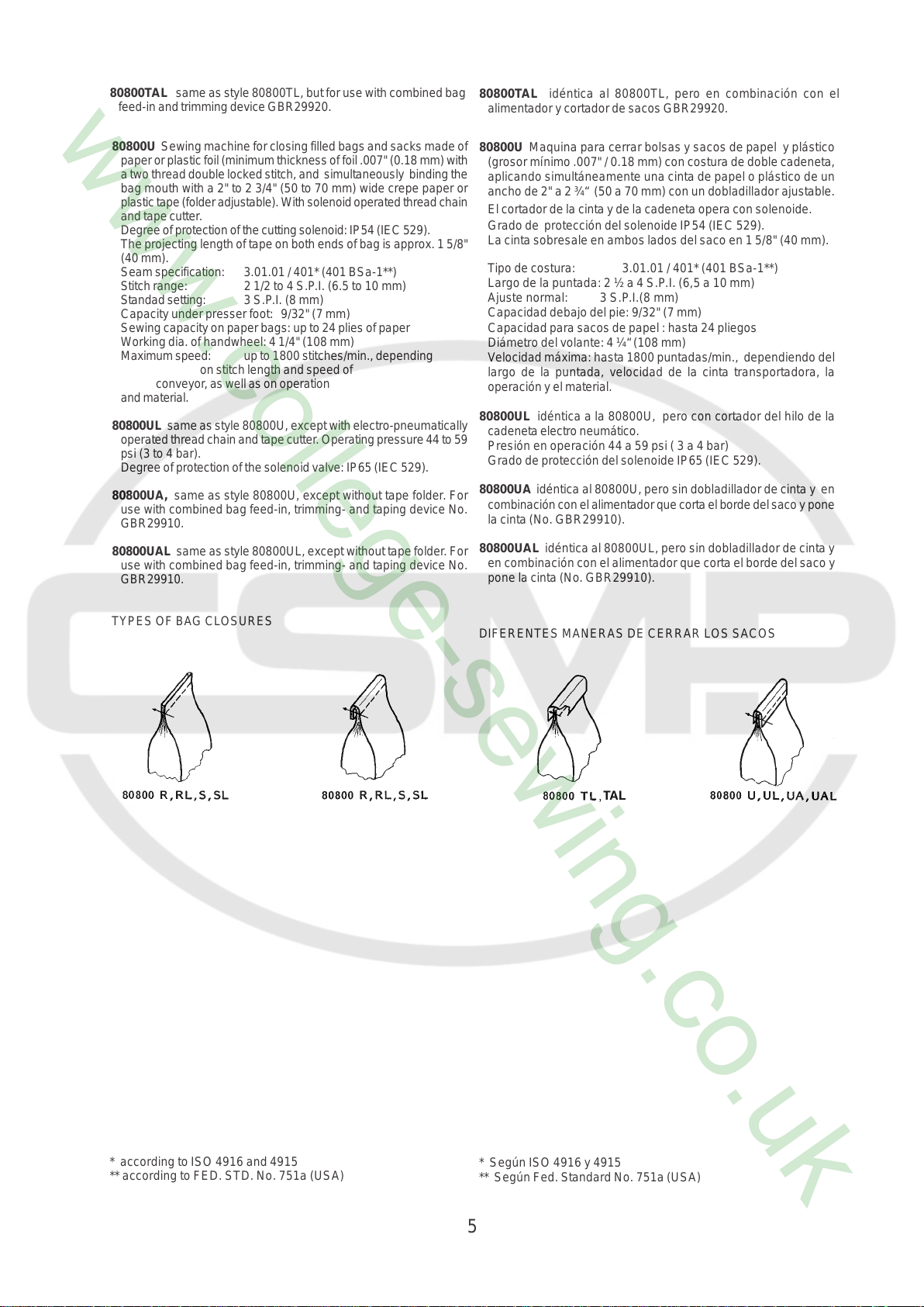
TYPES OF BAG CLOSURES
DIFERENTES MANERAS DE CERRAR LOS SACOS
* according to ISO 4916 and 4915
** according to FED. STD. No. 751a (USA)
* Según ISO 4916 y 4915
** Según Fed. Standard No. 751a (USA)
5
SAFETY RULES
IINDICACIONES DE SEGURIDAD
1. Before putting the machine described in this manual into
service, carefully read the instructions. The starting of each
machine is only permitted after taking notice of the instructions
and by qualified operators.
IMPORTANT! Before putting the machine into service, also
read the safety rules and instructions from the motor supplier.
2. Observe the national safety rules valid for your country.
3. The sewing machine described in this instruction manual is
prohibited from being put into service until it has been ascer-
tained that the sewing units which these sewing machines will
be built into, have conformed with the provisions of EC Machin-
ery Directive 98/37/EC, Annex II B.
The machine is only allowed to be used as foreseen. The
foreseen use of the particular machine is described in para-
graph STYLE OF MACHINE of this instruction manual. An-
other use, going beyond the description, is not as foreseen.
4. All safety devices must be in position when the machine
is ready for work or in operation. Operation of the machine
without the appertaining safety devices is prohibited.
5. Wear safety glasses.
6. In case of machine conversions and all valid safety rules must
be considered. Conversions and changes are made at your
own risk.
1. Antes de poner en marcha las maquinas descritas en este manual,
hay que leer cuidadosamente las instrucciones. El arranque de
cada maquina solamente se permite después de haber leído las
instrucciones y por personal calificado.
IMPORTANTE! También hay que leer las reglas de seguridad y
las instrucciones del fabricante del motor.
2. Observe las reglas nacionales de seguridad que rigen para su
país.
3. No se puede poner en marcha la maquina descrita en este manual
hasta que se confirme que la unidad de coser esta conforme con
el reglamento del Directivo de las Maquinas de la Comunidad
Europea 98/37/EC, Anexo II B.
La maquina solamente se puede utilizar para su uso previsto. El
uso previsto esta descrito en el capitulo ESTILO DE MAQUINAS
de este manual de instrucciones. Otro uso, diferente de la
descripción, no esta previsto.
4. Todos los dispositivos de seguridad tienen que estar en su sitio
cuando la maquina este lista para trabajar u operando. La operación
de la maquina sin los dispositivos de seguridad esta prohibida.
5. Utilice lentes de seguridad.
6. En el caso de una modificación de la maquina hay que tomar en
cuenta las reglas de seguridad. Modificaciones y cambios corren
por su riesgo.
7. Para las siguientes maniobras hay que desconectar la maquina del
suministro eléctrico apagando el interruptor principal o
desconectando el enchufe principal:
7. When doing the following machine has to be disconnected
from the power supply by turning off the main switch or by
pulling out the main plug.
7.1 When threading needle(s), looper, spreader
etc.
7.2 When replacing any parts such as needle(s),
presser foot, throat plate, looper, spreader,
feed dog, needle guard, folder, fabric guide
etc.
7.3 When leaving the workplace and when the
work place is unattended.
7.4 When doing maintenance work.
7.5 When using clutch motors without actuation
lock, wait until motor is stopped totally.
7.1 Enhebrando las agujas, looper, etc.
7.2 Reemplazando piezas como agujas, pie prensa tela, placa
de aguja, looper, diente de arrastre, guarda aguja, dobla-
dillador, etc.
7.3 Cuando salga de su puesto de trabajo y no se encuentre
nadie para atender la maquina.
7.4 Durante trabajos de mantenimiento.
7.5 Si esta utilizando motores de embrague, espere hasta que
el motor se detenga totalmente.
6
8. Maintenance, repair and conversion work (see item 7) must
be done only by trained technicians or special skilled person-
nel under condsideration of the instructions.
Only genuine spare parts approved by Union Special have to
be used for repairs.
9. Any work on the electrical equipment must be done by an
electrician or under direction and supervision of spe-
cial skilled personnel.
8. Mantenimiento, reparación y trabajos de conversión (vease
No. 7) solamente pueden ser efectuados por técnicos
entrenados o personal especializado bajo consideración de
las instrucciones.
Solamente repuestos originales y aprobados por Union
Special pueden ser utilizados para reparaciones.
9. Cualquier trabajo con el equipo eléctrico tiene que ser
ejecutado por un electricista o bajo la supervisión de personal
especialmente entrenado.
10. Work on parts and equipment under electrical power is not permitted.
Permissible exceptions are described in the applicable section of
standard sheet EN 50110 / VDE 0105.
11. Before doing maintenance and repair work on the pneumatic
equipment, the machine has to be discon- nected from the
compressed air supply. In case of existing residual air pres-
sure after disconnecting from compressed air supply (e.g.
pneumatic equipment with air tank), the pressure has to be
removed by bleeding. Exceptions are only allowed for adjust-
ing work and function checks done by special skilled person-
nel.
10. No esta permitido trabajar en piezas y equipos con la
electricidad conectada. Excepciones permitidas están
descritas en EN 50110 / VDE 0105.
11. Antes de hacer mantenimiento o reparaciones del equipo
neumático, hay que desconectar la maquina de la alimentación
del aire comprimido. En el caso que exista una presión de aire
residual después de desconectar la maquina (por ejemplo
equipos con tanques de aire), la presión tiene que ser
eliminada abriendo las válvulas. Excepciones están solamente
permitidas para trabajos de ajuste y revisión de funciones
por personal especialmente entrenado.
7
NOISE EMISSION
EMISION DE RUIDO
Equivalent continuous A-weighted sound pressure
level (L
10821-CB-M1 at 1400 RPM and 50 % duty cycle.
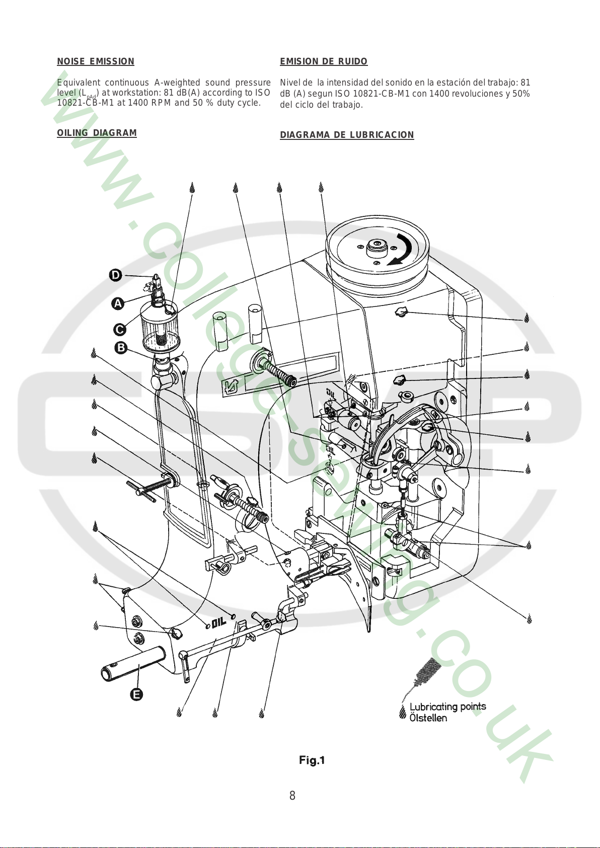
OILING DIAGRAM
) at workstation: 81 dB(A) according to ISO
pAd
Nivel de la intensidad del sonido en la estación del trabajo: 81
dB (A) segun ISO 10821-CB-M1 con 1400 revoluciones y 50%
del ciclo del trabajo.
DIAGRAMA DE LUBRICACION
8
LUBRICATION AND OPERATION
LUBRICACION Y OPERACIÓN
The machines of class 80800 have to be cleaned and lubricated
twice a day before the morning and afternoon start on the lubricating
points indicated on the oiling diagram (Fig. 1). The sight feed oiler
has to be kept filled and should be adjusted so that it feeds two to
three drops of oil per minute. The oiler has to be refilled latest, when
2/3 of the oil is used up.
For lubrication we recommend "Mobil Oil DTE Medium" or
equivalent, which can be purchased from UNION SPECIAL
CORPORATION in 1/2 liter containers under part number G28604L,
or in 5 liter containers under part no. G28604L-5.
Before operating a new machine for the first time, the needle bar
guard (E, Fig. 1) and the sight feed oiler, which come with the
accessories of the machine, have to be screwed in. The sight feed
oiler has to be adjusted. All lubricating points, indicated on the oiling
diagram (Fig. 1), have to be oiled.
For adjusting fill the sight feed oiler half-way with oil and turn the
metering pin (A, Fig. 1) a little bit out and then turn it in, until there
will flow approx. two drops of oil per minute. This can be checked
on the sight glass (B, Fig. 1). Secure the setting of the metering pin
with lock nut (C, Fig. 1). Fill the oiler.
Repeat the oiling of a new machine after 10 minutes of operation!
When the machine is out of operation, the oil flow can be stopped
by tilting the lever (D, Fig. 1) on the sight feed oiler.
IMPORTANT! The oil flow has to be switched on again before
operating the machine.
NEEDLES
Each needle has both a type and size number. The type number
denotes the kind of shank, point, length, groove, finish and other
details. The size number , stamped on the needle shank, denotes
largest diameter of blade, measured in hundredths of a millimeter
respectively in thousandths of an inch, midway between shank and
eye. Collectively, type and size number represent the complete
symbol, which is given on the label of all needles packaged and
sold by UNION SPECIAL.
The standard needle for machines covered in this manual is
9848G250/100.
For closing bags made of plastic or woven polypropylene tapes it is
recommended to use needle type 9856T with teflon coating.
Below are the descriptions and available sizes:
Type No. Description and sizes
9848G Round shank, square point, double groove,
spotted, chromium plated.
Sizes available: 150/060, 170/067, 200/080,
250/100, 300/120, 400/156.
9856T Round shank, round point, double groove,
spotted, teflon-coated.
Sizes available: 200/080, 250/100.
Selection of proper needle size is determined by size of thread used.
Thread should pass freely through needle eye in order to produce a
good stitch formation.
To have needle orders promptly and accurately filled, an empty
package, a sample needle or type and size number should be
forwarded. Use description on label. A complete order would read:
"100 needles, Type 9848G, Size 250/100".
Las maquinas de la clase 80800 tienen que ser limpiadas y lubricadas
dos veces al día antes del turno de la mañana y de la tarde en los
puntos de lubricación indicados en el diagrama de lubricación (Fig. 1).
El deposito del aceite hay que mantener lleno y debe estar ajustado
para que suelte dos a tres gotas de aceite por minuto. El deposito de
aceite debe ser rellenado cuando 2/3 del aceite fue gastado.
Para la lubricación recomendamos „Mobil Oil DTE Medium“ o su
equivalente, que puede ser adquirido de UNION SPECIAL
CORPORATION en envases de ½ litro bajo el P/P No. G28604L, o en
envases de 5 litros bajo el P/P No. G28604L-5.
Antes de operar la maquina por la primera vez, el protector de la barra
de la aguja (E, Fig. 1) y el deposito del aceite, que están en los
accesorios de la maquina, tienen que ser fijados en la maquina. El
deposito de aceite tiene que ser ajustado. Todos los puntos de
lubricación, indicados en el diagrama de lubricación (Fig. 1) hay que
lubricarlos.
Para el ajuste llene el deposito hasta la mitad con aceite y ajuste el
pasador de medición (A, Fig. 1) hasta que salgan aprox. dos gotas de
aceite por minuto. Esto puede ser revisado en el visor (B, Fig. 1).
Asegure la posición del pasador de medición con la tuerca (C, Fig. 1).
Llene el deposito con aceite.
Repita la lubricación de una nueva maquina después de 10 minutos de
operación!.
Cuando la maquina no esta operando, se para el flujo del aceite doblando
la palanca (D, Fig. 1) del deposito.
IMPORTANTE: Acuérdese de activar el flujo del aceite otra vez antes
de arrancar la maquina.
AGUJAS
Cada aguja tiene un numero del tipo y del grosor. El numero del tipo
determina el cabo, la punta, el largo, la ranura, la determinación y otros
detalles. El numero del grosor, troquelado en el cabo de la aguja,
significa el diámetro máximo de la aguja, expresado en centésimos de
un milímetro o milésimos de pulgada, entre el cabo y el ojo de la aguja.
En conjunto los números del tipo y del grosor representan el símbolo
completo, que aparece en la etiqueta de los empaques de las agujas,
que vende UNION SPECIAL.
La aguja común para las maquinas de este manual es la 9848G250/
100.
Para cerrar sacos de plástico o polipropileno tejido se recomienda el
uso de la aguja tipo 9856T con recubrimiento de teflon.
A continuación encuentra la descripción y los grosores disponibles::
Tipo numero: Descripción y grosores
9848G Cabo redondo, punta cortante, doble ranura,
cromado.
Grosores disponibles: 150/060, 170/067, 200/080,
250/100, 300/120, 400/156.
9856T Cabo Redondo, punta redonda, doble ranura,
recubrimiento de teflon.
Grosores disponibles: 200/080, 250/100.
La selección de la aguja apropiada esta determinada por el grosor del
hilo utilizado. El hilo debería pasar libremente por el ojo de la aguja,
para permitir una buena formación de la puntada.
Para asegurar que los pedidos de las agujas se cumplan rápido y
correctamente, se recomienda enviar un empaque vacío, una muestra
de una aguja o indicar los números del tipo o del grosor. Un pedido
completo seria: „100 agujas, tipo 9848G , grosor 250/100“.
THREADING
Thread machine as illustrated in Fig. 2.
When threading the looper, be sure the thread goes through the
front eyelets, over the take-up and through the back eyelet before
threading the looper.
ENHEBRAR
Enhebre la maquina como se demuestra en la Fig. 2.
Cuando enhebre el looper, asegúrese que el hilo pase por los ojetes
frontales, encima del alimentador y por el ojete trasero antes de pasarlo
por el looper.
9
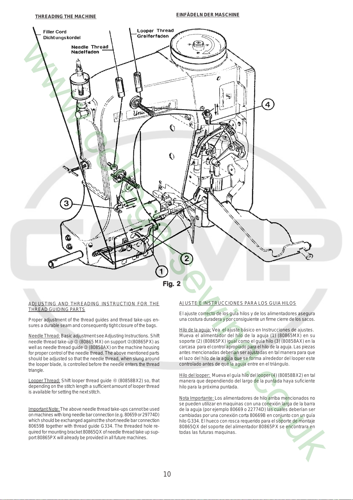
THREADING THE MACHINE
EINFÄDELN DER MASCHINE
ADJUSTING AND THREADING INSTRUCTION FOR THE
THREAD GUIDING PARTS
Proper adjustment of the thread guides and thread take-ups en-
sures a durable seam and consequently tight closure of the bags.
Needle Thread: Basic adjustment see Adjusting Instructions. Shift
needle thread take-up c (80865 MX) on support d(80865PX) as
well as needle thread guide e (80858AX) on the machine housing
for proper control of the needle thread. The above mentioned parts
should be adjusted so that the needle thread, when slung around
the looper blade, is controlled before the needle enters the thread
triangle.
Looper Thread: Shift looper thread guide f (80858BX2) so, that
depending on the stitch length a sufficient amount of looper thread
is available for setting the next stitch.
Important Note: The above needle thread take-ups cannot be used
on machines with long needle bar connection (e.g. 80659 or 29774D)
which should be exchanged against the short needle bar connection
80659B together with thread guide G334. The threaded hole re-
quired for mounting bracket 80865QX of needle thread take up sup-
port 80865PX will already be provided in all future machines.
FF
igig
. 2. 2
F
ig
. 2
FF
igig
. 2. 2
AJUSTE E INSTRUCCIONES P ARA LOS GUIA HILOS
El ajuste correcto de los guía hilos y de los alimentadores asegura
una costura duradera y por consiguiente un firme cierre de los sacos.
Hilo de la aguja: Vea el ajuste básico en Instrucciones de ajustes.
Mueva el alimentador del hilo de la aguja (1) (80865MX) en su
soporte (2) (80865PX) igual como el guía hilo (3) (80858AX) en la
carcasa para el control apropiado para el hilo de la aguja. Las piezas
antes mencionadas deberían ser ajustadas en tal manera para que
el lazo del hilo de la aguja que se forma alrededor del looper este
controlado antes de que la aguja entre en el triángulo.
Hilo del looper: Mueva el guía hilo del looper (4) (80858BX2) en tal
manera que dependiendo del largo de la puntada haya suficiente
hilo para la próxima puntada.
Nota Importante: Los alimentadores de hilo arriba mencionados no
se pueden utilizar en maquinas con una conexión larga de la barra
de la aguja (por ejemplo 80669 o 22774D) las cuales deberían ser
cambiadas por una conexión corta 80669B en conjunto con un guía
hilo G334. El hueco con rosca requerido para el soporte de montaje
80865QX del soporte del alimentador 80865PX se encontrara en
todas las futuras maquinas.
10

ADJUSTING INSTRUCTIONS
INSTRUCCIONES DEL AJUSTE
NOTE: Instructions stating direction or location, such as right, left,
front or rear of machine, are given relative to mechanic's
position in front of the machine, when the machine is placed
on an adjusting table, with the pulley to the right and the needle
bar in vertical position. The pulley rotates clockwise, in
operating direction; when viewed from the right end of the
machine.
INSERTING THE NEEDLE
Before adjusting the machine, insert a new needle with the shank as
far as possible into the needle bar. The long needle groove must
point to the front (toward the operator). Tighten the needle clamp nut
securely. Use the single ended open jaw wrench p art No. 21388 from
the accessories of the machine.
SETTING THE LOOPER
Remove the presser foot, throat plate and feed dog and on styles
80800TL, TAL, U, UA, UL and UAL also the needle guard for
convenient access to the machine. On styles 80800R, RL, S and SL
loosen the screw (A, Fig. 3) in the feed bar (B) and push the feed bar
needle guard (C) to the rear to avoid its contacting the needle (D).
For the two thread double locked stitch styles 80800R, RL, TL, T AL,
U, UA, UL and UAL, set the looper connecting rod (E) so the distance
(X, Fig. 4) between the center lines of the two ball joints is 69.8 mm (2
3/4"). The dimension (X, Fig. 4) should be 68.3 mm ( 2 11/16) on the
single thread chain stitch styles 80800S and SL. For adjustment
loosen the two nuts (F , Fig. 3) and turn connecting rod (E) forward or
backward as required to obtain specified dimension, retighten nuts
(F).
NOTE: The left nut has a left hand thread.
Set the looper (G) so the distance from the centerl ine of the needle
(D) to the looper (G) is 8 mm (5/16") when the looper is at its farthest
position to the right. Looper gauge No. 21225-5/16 can be used
advantageously in making this adjustment. For adjustment loosen
screws (H) in the looper drive lever (J), reposition as required to obtain
specified dimension and retighten screws (H) assuring that all end
play is taken out of the looper drive lever rocker shaft. Check to insure
a clearance of approx. 1 mm (.040") between the point of the looper
and the bed end cover when the looper is at its extreme left position.
Should the looper strike the bed end cover, recheck the distance
between center lines of ball joints and the looper gauge distance as
described above.
Rotate the machine pulley in operating direction so that the looper
moves from right to left. The looper point should pass as close as
possible to the back of the needle without contacting 0.08 to 0.13 mm
(.003 to .005") clearance. For adjustment loosen screws (A, Fig. 4)
in the looper eccentric fork (B) and turn looper rocker shaft (C) on the
looper rocker forward or backward as required. Retighten screw (A).
NOTA: T odas las indicaciones como derecho, izquierdo, adelante o atrás,
se refieren a la posición del mecánico en frente de la maquina,
con la maquina puesta en una mesa de trabajo, con el volante a
la derecha y la barra de la aguja en posición vertical. El volante
gira en sentido de reloj para la operación, desde el punto de vista
del lado derecho de la maquina.
INSERTAR LA AGUJA
Antes de ajustar la maquina debe insertar una nueva aguja con el cabo
de la aguja en la barra de la aguja. Las ranuras de las agujas deben
estar hacia adelante (hacia el operador). Apriéte la tuerca que fija la
aguja firmemente. Utilíze la llave P/P No. 21388 de los accesorios de la
maquina.
AJUSTE DEL LOOPER
Quite el pie prensa tela, la placa de la aguja y el diente de arrastre y en
las maquinas 80800TL, TAL, UA, UL y UAL t ambién el guarda aguja
para tener mejor acceso a la maquina. En los estilos 80800R, RL, S, y
SL suelte el tornillo (A, Fig.3) en la barra de alimentación B y mueva el
guarda aguja (C) en la barra de alimentación hacia atrás para evitar
que tenga contacto con la aguja (D).
Para las maquinas de dos hilos como 80800R, RL, TL, T AL, U, UA, UL
y UAL ajuste la barra del looper (E) para que la distancia (X, Fig. 4)
entre los centros de las junturas tenga una distancia de 69,8 mm (2 3/
4"). Esta distancia (X, Fig. 4) debería ser 68,3 mm (2 11/16) en las
maquinas de un solo hilo 80800 S y SL. Para ajustarlo suelte las dos
tuercas (F , Fig. 3) y gire la barra (E) hacia adelante o hacia atrás para
conseguir la distancia requerida. Apriete nuevamente las tuercas (F).
NOTA: La tuerca izquierda tiene una rosca izquierda.
Ponga el looper (G) de manera tal que la distancia entre el medio de la
aguja (D) al looper (G) sea de 8 mm (5/16) cuando el looper se
encuentre en su posición a la extrema derecha. El calibrador P/P No.
21225-5/16 puede ser utilizado para un ajuste preliminar. Para ajust ar
suelte los tornillos (H) en la palanca (J) del looper, mueva la p alanca
para obtener la distancia requerida y apriete los tornillos (H), asegurando
que la barra del accionamiento del looper no tenga juego. Asegure que
haya una distancia de aprox. 1 mm (.040") entre la punta del looper y la
tapa final de la maquina cuando el looper se encuentre en su posición
de la extrema izquierda. Si el looper tocaría la tapa, revise otra vez la
distancia entre los centros de las junturas y la distancia entre el looper
y la aguja como se ha descrito anteriormente.
Gire el volante en sentido de operación para que el looper se mueva
desde la derecha hacia la izquierda. La punta del looper debería pasar
muy cerca detrás de la aguja sin tocarla – distancia 0.08 a 0,13 mm
(.003 a .005"). Para lograr este ajuste debería soltar el tornillo (A, Fig.
4) en la horquilla excéntrica (B) del looper y girar el eje del looper (C)
hacia adelante o hacia atrás. Apriete el tornillo (A) otra vez.
Fig. 3
11
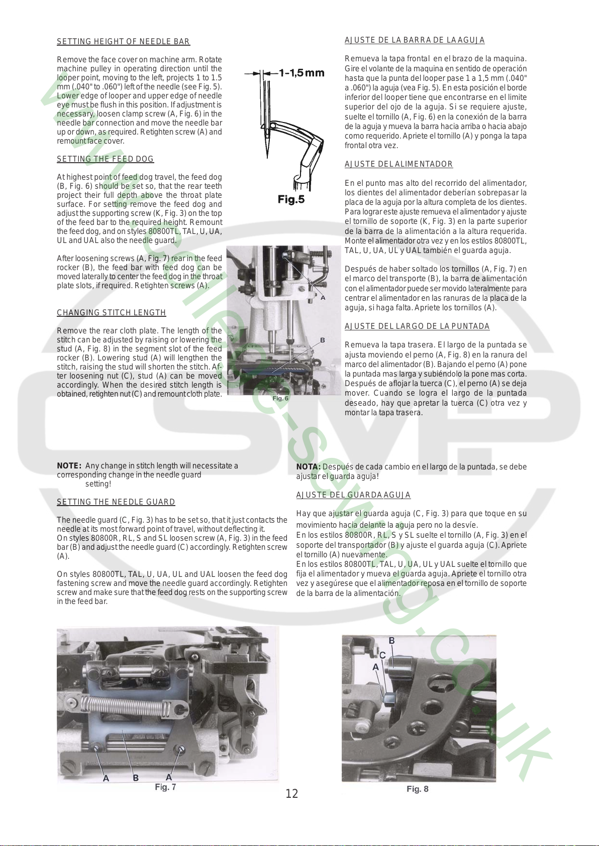
SETTING HEIGHT OF NEEDLE BAR
AJUSTE DE LA BARRA DE LA AGUJA
Remove the face cover on machine arm. Rotate
machine pulley in operating direction until the
looper point, moving to the left, projects 1 to 1.5
mm (.040" to .060") left of the needle (see Fig. 5).
Lower edge of looper and upper edge of needle
eye must be flush in this position. If adjustment is
necessary, loosen clamp screw (A, Fig. 6) in the
needle bar connection and move the needle bar
up or down, as required. Retighten screw (A) and
remount face cover.
SETTING THE FEED DOG
At highest point of feed dog travel, the feed dog
(B, Fig. 6) should be set so, that the rear teeth
project their full depth above the throat plate
surface. For setting remove the feed dog and
adjust the supporting screw (K, Fig. 3) on the top
of the feed bar to the required height. Remount
the feed dog, and on styles 80800TL, T AL, U, UA,
UL and UAL also the needle guard.
After loosening screws (A, Fig. 7) rear in the feed
rocker (B), the feed bar with feed dog can be
moved laterally to center the feed dog in the throat
plate slots, if required. Retighten screws (A).
CHANGING STITCH LENGTH
Remove the rear cloth plate. The length of the
stitch can be adjusted by raising or lowering the
stud (A, Fig. 8) in the segment slot of the feed
rocker (B). Lowering stud (A) will lengthen the
stitch, raising the stud will shorten the stitch. Af-
ter loosening nut (C), stud (A) can be moved
accordingly. When the desired stitch length is
obtained, retighten nut (C) and remount cloth plate.
Remueva la tapa frontal en el brazo de la maquina.
Gire el volante de la maquina en sentido de operación
hasta que la punta del looper pase 1 a 1,5 mm (.040"
a .060") la aguja (vea Fig. 5). En esta posición el borde
inferior del looper tiene que encontrarse en el limite
superior del ojo de la aguja. Si se requiere ajuste,
suelte el tornillo (A, Fig. 6) en la conexión de la barra
de la aguja y mueva la barra hacia arriba o hacia abajo
como requerido. Apriete el tornillo (A) y ponga la tapa
frontal otra vez.
AJUSTE DEL ALIMENTADOR
En el punto mas alto del recorrido del alimentador,
los dientes del alimentador deberían sobrepasar la
placa de la aguja por la altura completa de los dientes.
Para lograr este ajuste remueva el alimentador y ajuste
el tornillo de soporte (K, Fig. 3) en la parte superior
de la barra de la alimentación a la altura requerida.
Monte el alimentador otra vez y en los estilos 80800TL,
TAL, U, UA, UL y UAL también el guarda aguja.
Después de haber soltado los tornillos (A, Fig. 7) en
el marco del transporte (B), la barra de alimentación
con el alimentador puede ser movido lateralmente para
centrar el alimentador en las ranuras de la placa de la
aguja, si haga falta. Apriete los tornillos (A).
AJUSTE DEL LARGO DE LA PUNT ADA
Remueva la tapa trasera. El largo de la puntada se
ajusta moviendo el perno (A, Fig. 8) en la ranura del
marco del alimentador (B). Bajando el perno (A) pone
la puntada mas larga y subiéndolo la pone mas corta.
Después de aflojar la tuerca (C), el perno (A) se deja
mover. Cuando se logra el largo de la puntada
deseado, hay que apretar la tuerca (C) otra vez y
montar la tapa trasera.
NOTE: Any change in stitch length will necessitate a
corresponding change in the needle guard
setting!
SETTING THE NEEDLE GUARD
The needle guard (C, Fig. 3) has to be set so, that it just contacts the
needle at its most forward point of travel, without deflecting it.
On styles 80800R, RL, S and SL loosen screw (A, Fig. 3) in the feed
bar (B) and adjust the needle guard (C) accordingly. Retighten screw
(A).
On styles 80800TL, TAL, U, UA, UL and UAL loosen the feed dog
fastening screw and move the needle guard accordingly. Retighten
screw and make sure that the feed dog rests on the supporting screw
in the feed bar.
NOT A: Después de cada cambio en el largo de la puntada, se debe
ajustar el guarda aguja!
AJUSTE DEL GUARDA AGUJA
Hay que ajustar el guarda aguja (C, Fig. 3) para que toque en su
movimiento hacia delante la aguja pero no la desvíe.
En los estilos 80800R, RL, S y SL suelte el tornillo (A, Fig. 3) en el
soporte del transportador (B) y ajuste el guarda aguja (C). Apriete
el tornillo (A) nuevamente.
En los estilos 80800TL, T AL, U, UA, UL y UAL suelte el tornillo que
fija el alimentador y mueva el guarda aguja. Apriete el tornillo otra
vez y asegúrese que el alimentador reposa en el tornillo de soporte
de la barra de la alimentación.
12
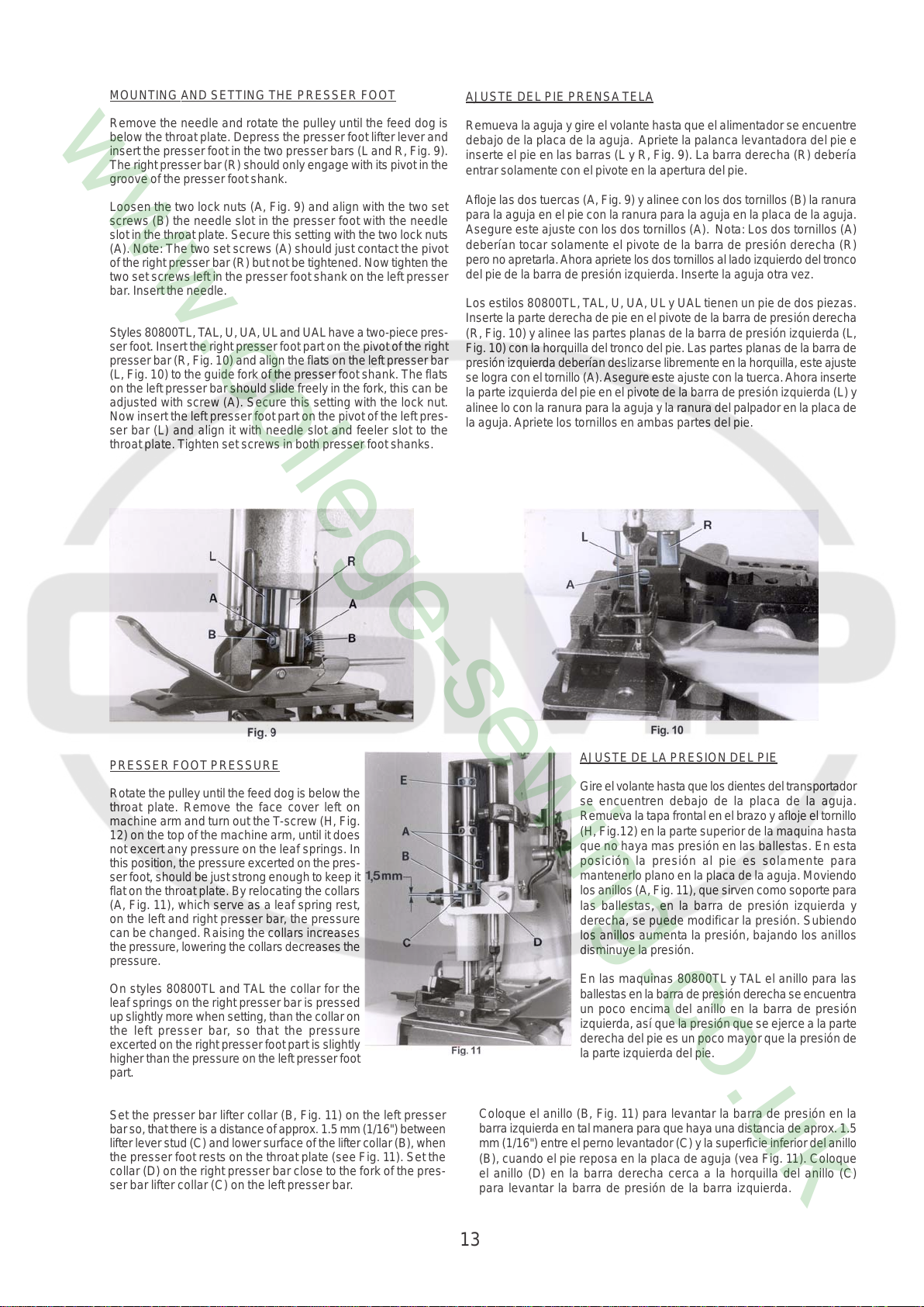
MOUNTING AND SETTING THE PRESSER FOOT
AJUSTE DEL PIE PRENSA TELA
Remove the needle and rotate the pulley until the feed dog is
below the throat plate. Depress the presser foot lifter lever and
insert the presser foot in the two presser bars (L and R, Fig. 9).
The right presser bar (R) should only engage with its pivot in the
groove of the presser foot shank.
Loosen the two lock nuts (A, Fig. 9) and align with the two set
screws (B) the needle slot in the presser foot with the needle
slot in the throat plate. Secure this setting with the two lock nuts
(A). Note: The two set screws (A) should just contact the pivot
of the right presser bar (R) but not be tightened. Now tighten the
two set screws left in the presser foot shank on the left presser
bar. Insert the needle.
Styles 80800TL, T AL, U, UA, UL and UAL have a two-piece pres-
ser foot. Insert the right presser foot part on the pivot of the right
presser bar (R, Fig. 10) and align the flats on the left presser bar
(L, Fig. 10) to the guide fork of the presser foot shank. The flats
on the left presser bar should slide freely in the fork, this can be
adjusted with screw (A). Secure this setting with the lock nut.
Now insert the left presser foot part on the pivot of the left pres-
ser bar (L) and align it with needle slot and feeler slot to the
throat plate. Tighten set screws in both presser foot shanks.
Remueva la aguja y gire el volante hasta que el alimentador se encuentre
debajo de la placa de la aguja. Apriete la palanca levantadora del pie e
inserte el pie en las barras (L y R, Fig. 9). La barra derecha (R) debería
entrar solamente con el pivote en la apertura del pie.
Afloje las dos tuercas (A, Fig. 9) y alinee con los dos tornillos (B) la ranura
para la aguja en el pie con la ranura para la aguja en la placa de la aguja.
Asegure este ajuste con los dos tornillos (A). Nota: Los dos tornillos (A)
deberían tocar solamente el pivote de la barra de presión derecha (R)
pero no apretarla. Ahora apriete los dos tornillos al lado izquierdo del tronco
del pie de la barra de presión izquierda. Inserte la aguja otra vez.
Los estilos 80800TL, T AL, U, UA, UL y UAL tienen un pie de dos piezas.
Inserte la parte derecha de pie en el pivote de la barra de presión derecha
(R, Fig. 10) y alinee las partes planas de la barra de presión izquierda (L,
Fig. 10) con la horquilla del tronco del pie. Las partes planas de la barra de
presión izquierda deberían deslizarse libremente en la horquilla, este ajuste
se logra con el tornillo (A). Asegure este ajuste con la tuerca. Ahora inserte
la parte izquierda del pie en el pivote de la barra de presión izquierda (L) y
alinee lo con la ranura para la aguja y la ranura del palpador en la placa de
la aguja. Apriete los tornillos en ambas partes del pie.
PRESSER FOOT PRESSURE
Rotate the pulley until the feed dog is below the
throat plate. Remove the face cover left on
machine arm and turn out the T-screw (H, Fig.
12) on the top of the machine arm, until it does
not excert any pressure on the leaf springs. In
this position, the pressure excerted on the pres-
ser foot, should be just strong enough to keep it
flat on the throat plate. By relocating the collars
(A, Fig. 11), which serve as a leaf spring rest,
on the left and right presser bar, the pressure
can be changed. Raising the collars increases
the pressure, lowering the collars decreases the
pressure.
On styles 80800TL and TAL the collar for the
leaf springs on the right presser bar is pressed
up slightly more when setting, than the collar on
the left presser bar, so that the pressure
excerted on the right presser foot part is slightly
higher than the pressure on the left presser foot
part.
Set the presser bar lifter collar (B, Fig. 11) on the lef t presser
bar so, that there is a distance of approx. 1.5 mm (1/16") between
lifter lever stud (C) and lower surface of the lifter collar (B), when
the presser foot rests on the throat plate (see Fig. 11). Set the
collar (D) on the right presser bar close to the fork of the pres-
ser bar lifter collar (C) on the left presser bar.
AJUSTE DE LA PRESION DEL PIE
Gire el volante hasta que los dientes del transportador
se encuentren debajo de la placa de la aguja.
Remueva la tapa frontal en el brazo y afloje el tornillo
(H, Fig.12) en la parte superior de la maquina hasta
que no haya mas presión en las ballestas. En esta
posición la presión al pie es solamente para
mantenerlo plano en la placa de la aguja. Moviendo
los anillos (A, Fig. 11), que sirven como soporte para
las ballestas, en la barra de presión izquierda y
derecha, se puede modificar la presión. Subiendo
los anillos aumenta la presión, bajando los anillos
disminuye la presión.
En las maquinas 80800TL y TAL el anillo para las
ballestas en la barra de presión derecha se encuentra
un poco encima del anillo en la barra de presión
izquierda, así que la presión que se ejerce a la parte
derecha del pie es un poco mayor que la presión de
la parte izquierda del pie.
Coloque el anillo (B, Fig. 11) para levantar la barra de presión en la
barra izquierda en tal manera para que haya una distancia de aprox. 1.5
mm (1/16") entre el perno levantador (C) y la superficie inferior del anillo
(B), cuando el pie reposa en la placa de aguja (vea Fig. 11). Coloque
el anillo (D) en la barra derecha cerca a la horquilla del anillo (C)
para levantar la barra de presión de la barra izquierda.
13
PRESSURE FOOT PRESSURE (continued)
AJUSTE DE LA PRESION DEL PIE (continuación)
On styles 80800TL and TAL set the collar (D, Fig. 11) on the
right presser bar approx. 2.5 mm (7/64") above the fork of the
presser bar lifter collar (B). This effects, when lifting the pres-
ser foot, that the left presser foot part is lifted first by approx. 2.5
mm (7/64"), before the right presser foot part will lift too.
The presser foot lift is limited with the upper stop collar (E, Fig.
11) on the left presser bar. When the needle is in its lowest
position and the presser foot is lifted with presser foot bottom
tilted up, the needle bar respectively needle clamp nut should
not contact the presser foot bottom. Set collar (E) accordingly.
Now turn in T-screw (H, Fig. 12) until the necessary presser
foot pressure for proper feeding is excerted (determine by sewing
tests). Secure this setting with the knurled nut (J), which
simultaneously fastens the upper arm cover. Remount the face
cover.
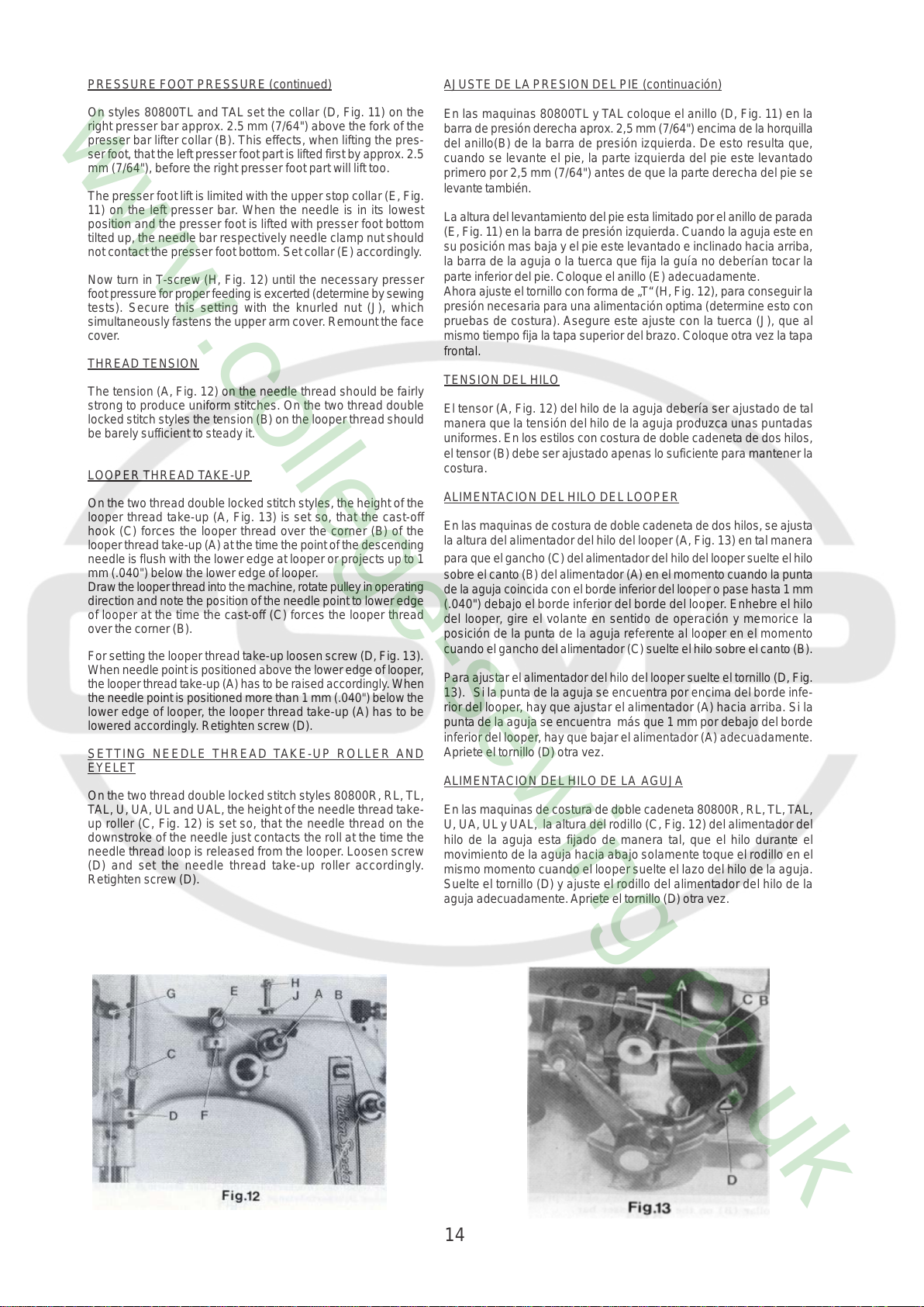
THREAD TENSION
The tension (A, Fig. 12) on the needle thread should be fairly
strong to produce uniform stitches. On the two thread double
locked stitch styles the tension (B) on the looper thread should
be barely sufficient to steady it.
LOOPER THREAD TAKE-UP
On the two thread double locked stitch styles, the height of the
looper thread take-up (A, Fig. 13) is set so, that the cast-off
hook (C) forces the looper thread over the corner (B) of the
looper thread take-up (A) at the time the point of the descending
needle is flush with the lower edge at looper or projects up to 1
mm (.040") below the lower edge of looper.
Draw the looper thread into the machine, rotate pulley in operating
direction and note the position of the needle point to lower edge
of looper at the time the cast-off (C) forces the looper thread
over the corner (B).
For setting the looper thread take-up loosen screw (D, Fig. 13).
When needle point is positioned above the lower edge of looper,
the looper thread take-up (A) has to be raised accordingly . When
the needle point is positioned more than 1 mm (.040") below the
lower edge of looper, the looper thread take-up (A) has to be
lowered accordingly. Retighten screw (D).
SETTING NEEDLE THREAD TAKE-UP ROLLER AND
EYELET
On the two thread double locked stitch styles 80800R, RL, TL,
TAL, U, UA, UL and UAL, the height of the needle thread take-
up roller (C, Fig. 12) is set so, that the needle thread on the
downstroke of the needle just contacts the roll at the time the
needle thread loop is released from the looper. Loosen screw
(D) and set the needle thread take-up roller accordingly.
Retighten screw (D).
En las maquinas 80800TL y TAL coloque el anillo (D, Fig. 11) en la
barra de presión derecha aprox. 2,5 mm (7/64") encima de la horquilla
del anillo(B) de la barra de presión izquierda. De esto resulta que,
cuando se levante el pie, la parte izquierda del pie este levantado
primero por 2,5 mm (7/64") antes de que la parte derecha del pie se
levante también.
La altura del levantamiento del pie esta limitado por el anillo de parada
(E, Fig. 11) en la barra de presión izquierda. Cuando la aguja este en
su posición mas baja y el pie este levantado e inclinado hacia arriba,
la barra de la aguja o la tuerca que fija la guía no deberían tocar la
parte inferior del pie. Coloque el anillo (E) adecuadamente.
Ahora ajuste el tornillo con forma de „T“ (H, Fig. 12), para conseguir la
presión necesaria para una alimentación optima (determine esto con
pruebas de costura). Asegure este ajuste con la tuerca (J), que al
mismo tiempo fija la tapa superior del brazo. Coloque otra vez la tapa
frontal.
TENSION DEL HILO
El tensor (A, Fig. 12) del hilo de la aguja debería ser ajustado de tal
manera que la tensión del hilo de la aguja produzca unas puntadas
uniformes. En los estilos con costura de doble cadeneta de dos hilos,
el tensor (B) debe ser ajustado apenas lo suficiente para mantener la
costura.
ALIMENTACION DEL HILO DEL LOOPER
En las maquinas de costura de doble cadeneta de dos hilos, se ajusta
la altura del alimentador del hilo del looper (A, Fig. 13) en tal manera
para que el gancho (C) del alimentador del hilo del looper suelte el hilo
sobre el canto (B) del alimentador (A) en el momento cuando la punta
de la aguja coincida con el borde inferior del looper o pase hasta 1 mm
(.040") debajo el borde inferior del borde del looper. Enhebre el hilo
del looper, gire el volante en sentido de operación y memorice la
posición de la punta de la aguja referente al looper en el momento
cuando el gancho del alimentador (C) suelte el hilo sobre el canto (B).
Para ajustar el alimentador del hilo del looper suelte el tornillo (D, Fig.
13). Si la punta de la aguja se encuentra por encima del borde infe-
rior del looper, hay que ajustar el alimentador (A) hacia arriba. Si la
punta de la aguja se encuentra más que 1 mm por debajo del borde
inferior del looper, hay que bajar el alimentador (A) adecuadamente.
Apriete el tornillo (D) otra vez.
ALIMENTACION DEL HILO DE LA AGUJA
En las maquinas de costura de doble cadeneta 80800R, RL, TL, T AL,
U, UA, UL y UAL, la altura del rodillo (C, Fig. 12) del alimentador del
hilo de la aguja esta fijado de manera tal, que el hilo durante el
movimiento de la aguja hacia abajo solamente toque el rodillo en el
mismo momento cuando el looper suelte el lazo del hilo de la aguja.
Suelte el tornillo (D) y ajuste el rodillo del alimentador del hilo de la
aguja adecuadamente. Apriete el tornillo (D) otra vez.
14
SETTING NEEDLE THREAD TAKE-UP ROLLER AND EYELET
continued
On the single thread chain stitch styles 80800S and SL, the needle
thread take-up roller (C) should be positioned so as not to contact
the needle thread at any time.
On all styles the eyelet (E, Fig. 12) should be positioned so, that
the needle thread runs nearly horizontal, parallel to cloth plate,
between eyelet (G) on needle bar connection and eyelet (E) on
machine arm, when the needle is in its upmost position. Eyelet
(E) is secured by screw (F).
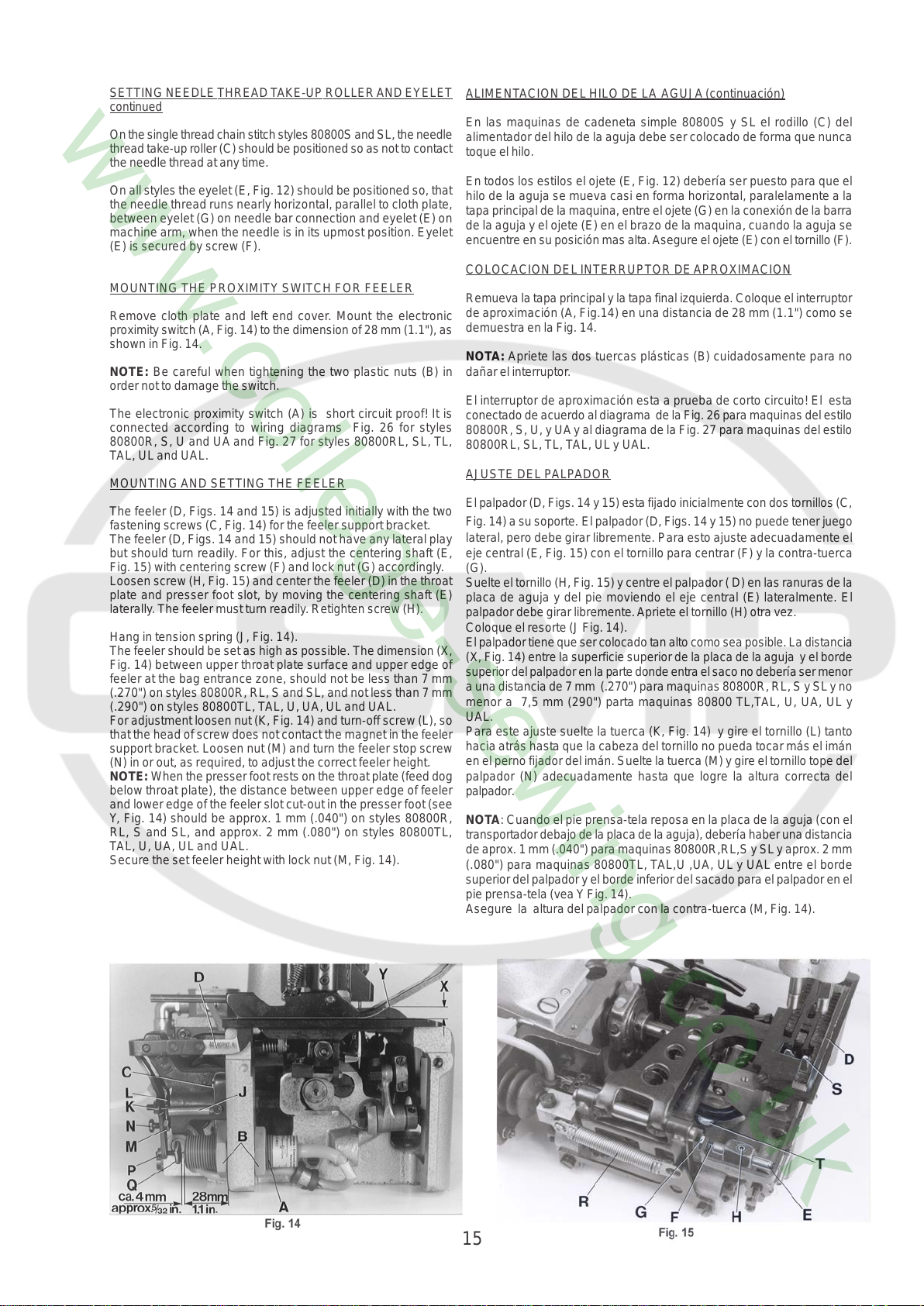
MOUNTING THE PROXIMITY SWITCH FOR FEELER
Remove cloth plate and left end cover. Mount the electronic
proximity switch (A, Fig. 14) to the dimension of 28 mm (1.1"), as
shown in Fig. 14.
NOTE: Be careful when tightening the two plastic nuts (B) in
order not to damage the switch.
The electronic proximity switch (A) is short circuit proof! It is
connected according to wiring diagrams Fig. 26 for styles
80800R, S, U and UA and Fig. 27 for styles 80800RL, SL, TL,
TAL, UL and UAL.
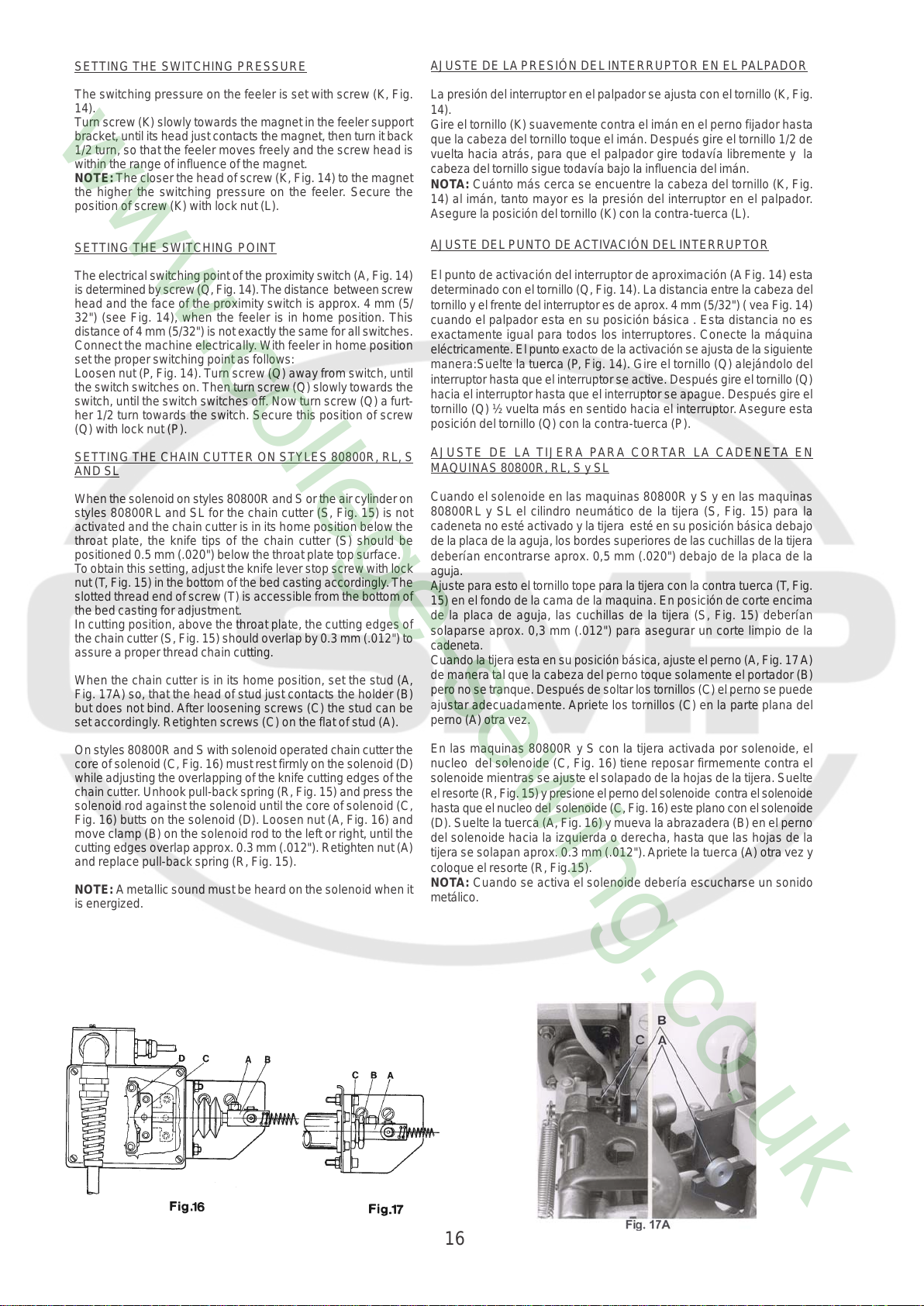
MOUNTING AND SETTING THE FEELER
The feeler (D, Figs. 14 and 15) is adjusted initially with the two
fastening screws (C, Fig. 14) for the feeler support bracket.
The feeler (D, Figs. 14 and 15) should not have any lateral play
but should turn readily. For this, adjust the centering shaft (E,
Fig. 15) with centering screw (F) and lock nut (G) accordingly.
Loosen screw (H, Fig. 15) and center the feeler (D) in the throat
plate and presser foot slot, by moving the centering shaft (E)
laterally. The feeler must turn readily . Retighten screw (H).
Hang in tension spring (J, Fig. 14).
The feeler should be set as high as possible. The dimension (X,
Fig. 14) between upper throat plate surface and upper edge of
feeler at the bag entrance zone, should not be less than 7 mm
(.270") on styles 80800R, RL, S and SL, and not less than 7 mm
(.290") on styles 80800TL, TAL, U, UA, UL and UAL.
For adjustment loosen nut (K, Fig. 14) and turn-off screw (L), so
that the head of screw does not contact the magnet in the feeler
support bracket. Loosen nut (M) and turn the feeler stop screw
(N) in or out, as required, to adjust the correct feeler height.
NOTE: When the presser foot rests on the throat plate (feed dog
below throat plate), the distance between upper edge of feeler
and lower edge of the feeler slot cut-out in the presser foot (see
Y, Fig. 14) should be approx. 1 mm (.040") on styles 80800R,
RL, S and SL, and approx. 2 mm (.080") on styles 80800TL,
TAL, U, UA, UL and UAL.
Secure the set feeler height with lock nut (M, Fig. 14).
ALIMENTACION DEL HILO DE LA AGUJA (continuación)
En las maquinas de cadeneta simple 80800S y SL el rodillo (C) del
alimentador del hilo de la aguja debe ser colocado de forma que nunca
toque el hilo.
En todos los estilos el ojete (E, Fig. 12) debería ser puesto para que el
hilo de la aguja se mueva casi en forma horizontal, paralelamente a la
tapa principal de la maquina, entre el ojete (G) en la conexión de la barra
de la aguja y el ojete (E) en el brazo de la maquina, cuando la aguja se
encuentre en su posición mas alta. Asegure el ojete (E) con el tornillo (F).
COLOCACION DEL INTERRUPTOR DE APROXIMACION
Remueva la tapa principal y la tapa final izquierda. Coloque el interruptor
de aproximación (A, Fig.14) en una distancia de 28 mm (1.1") como se
demuestra en la Fig. 14.
NOTA: Apriete las dos tuercas plásticas (B) cuidadosamente para no
dañar el interruptor.
El interruptor de aproximación esta a prueba de corto circuito! El esta
conectado de acuerdo al diagrama de la Fig. 26 para maquinas del estilo
80800R, S, U, y UA y al diagrama de la Fig. 27 p ara maquinas del estilo
80800RL, SL, TL, T AL, UL y UAL.
AJUSTE DEL PALPADOR
El palpador (D, Figs. 14 y 15) esta fijado inicialmente con dos tornillos (C,
Fig. 14) a su soporte. El palpador (D, Figs. 14 y 15) no puede tener juego
lateral, pero debe girar libremente. Para esto ajuste adecuadamente el
eje central (E, Fig. 15) con el tornillo para centrar (F) y la contra-tuerca
(G).
Suelte el tornillo (H, Fig. 15) y centre el palpador ( D) en las ranuras de la
placa de aguja y del pie moviendo el eje central (E) lateralmente. El
palpador debe girar libremente. Apriete el tornillo (H) otra vez.
Coloque el resorte (J Fig. 14).
El palpador tiene que ser colocado tan alto como sea posible. La distancia
(X, Fig. 14) entre la superficie superior de la placa de la aguja y el borde
superior del palpador en la parte donde entra el saco no debería ser menor
a una distancia de 7 mm (.270") para maquinas 80800R, RL, S y SL y no
menor a 7,5 mm (290") parta maquinas 80800 TL,TAL, U, UA, UL y
UAL.
Para este ajuste suelte la tuerca (K, Fig. 14) y gire el tornillo (L) tanto
hacia atrás hasta que la cabeza del tornillo no pueda tocar más el imán
en el perno fijador del imán. Suelte la tuerca (M) y gire el tornillo tope del
palpador (N) adecuadamente hasta que logre la altura correcta del
palpador.
NOTA: Cuando el pie prensa-tela reposa en la placa de la aguja (con el
transportador debajo de la placa de la aguja), debería haber una distancia
de aprox. 1 mm (.040") para maquinas 80800R,RL,S y SL y aprox. 2 mm
(.080") para maquinas 80800TL, TAL,U ,UA, UL y UAL entre el borde
superior del palpador y el borde inferior del sacado para el palpador en el
pie prensa-tela (vea Y Fig. 14).
Asegure la altura del palpador con la contra-tuerca (M, Fig. 14).
15
SETTING THE SWITCHING PRESSURE
AJUSTE DE LA PRESIÓN DEL INTERRUPTOR EN EL PALPADOR
The switching pressure on the feeler is set with screw (K, Fig.
14).
Turn screw (K) slowly towards the magnet in the feeler support
bracket, until its head just contacts the magnet, then turn it back
1/2 turn, so that the feeler moves freely and the screw head is
within the range of influence of the magnet.
NOTE: The closer the head of screw (K, Fig. 14) to the magnet
the higher the switching pressure on the feeler. Secure the
position of screw (K) with lock nut (L).
SETTING THE SWITCHING POINT
The electrical switching point of the proximity switch (A, Fig. 14)
is determined by screw (Q, Fig. 14). The distance between screw
head and the face of the proximity switch is approx. 4 mm (5/
32") (see Fig. 14), when the feeler is in home position. This
distance of 4 mm (5/32") is not exactly the same for all switches.
Connect the machine electrically . With feeler in home position
set the proper switching point as follows:
Loosen nut (P , Fig. 14). Turn screw (Q) away from switch, until
the switch switches on. Then turn screw (Q) slowly towards the
switch, until the switch switches off. Now turn screw (Q) a furt-
her 1/2 turn towards the switch. Secure this position of screw
(Q) with lock nut (P).
SETTING THE CHAIN CUTTER ON STYLES 80800R, RL, S
AND SL
When the solenoid on styles 80800R and S or the air cylinder on
styles 80800RL and SL for the chain cutter (S, Fig. 15) is not
activated and the chain cutter is in its home position below the
throat plate, the knife tips of the chain cutter (S) should be
positioned 0.5 mm (.020") below the throat plate top surface.
T o obtain this setting, adjust the knife lever stop screw with lock
nut (T , Fig. 15) in the bottom of the bed casting accordingly . The
slotted thread end of screw (T) is accessible from the bottom of
the bed casting for adjustment.
In cutting position, above the throat plate, the cutting edges of
the chain cutter (S, Fig. 15) should overlap by 0.3 mm (.012") to
assure a proper thread chain cutting.
When the chain cutter is in its home position, set the stud (A,
Fig. 17A) so, that the head of stud just contacts the holder (B)
but does not bind. After loosening screws (C) the stud can be
set accordingly. Retighten screws (C) on the flat of stud (A).
On styles 80800R and S with solenoid operated chain cutter the
core of solenoid (C, Fig. 16) must rest firmly on the solenoid (D)
while adjusting the overlapping of the knife cutting edges of the
chain cutter. Unhook pull-back spring (R, Fig. 15) and press the
solenoid rod against the solenoid until the core of solenoid (C,
Fig. 16) butts on the solenoid (D). Loosen nut (A, Fig. 16) and
move clamp (B) on the solenoid rod to the left or right, until the
cutting edges overlap approx. 0.3 mm (.012"). Retighten nut (A)
and replace pull-back spring (R, Fig. 15).
NOTE: A metallic sound must be heard on the solenoid when it
is energized.
La presión del interruptor en el palpador se ajusta con el tornillo (K, Fig.
14).
Gire el tornillo (K) suavemente contra el imán en el perno fijador hasta
que la cabeza del tornillo toque el imán. Después gire el tornillo 1/2 de
vuelta hacia atrás, para que el palpador gire todavía libremente y la
cabeza del tornillo sigue todavía bajo la influencia del imán.
NOTA: Cuánto más cerca se encuentre la cabeza del tornillo (K, Fig.
14) al imán, tanto mayor es la presión del interruptor en el palpador.
Asegure la posición del tornillo (K) con la contra-tuerca (L).
AJUSTE DEL PUNTO DE ACTIVACIÓN DEL INTERRUPTOR
El punto de activación del interruptor de aproximación (A Fig. 14) esta
determinado con el tornillo (Q, Fig. 14). La distancia entre la cabeza del
tornillo y el frente del interruptor es de aprox. 4 mm (5/32") ( vea Fig. 14)
cuando el palpador esta en su posición básica . Esta distancia no es
exactamente igual para todos los interruptores. Conecte la máquina
eléctricamente. El punto exacto de la activación se ajusta de la siguiente
manera:Suelte la tuerca (P, Fig. 14). Gire el tornillo (Q) alejándolo del
interruptor hasta que el interruptor se active. Después gire el tornillo (Q)
hacia el interruptor hasta que el interruptor se apague. Después gire el
tornillo (Q) ½ vuelta más en sentido hacia el interruptor. Asegure esta
posición del tornillo (Q) con la contra-tuerca (P).
AJUSTE DE LA TIJERA PARA CORTAR LA CADENETA EN
MAQUINAS 80800R, RL, S y SL
Cuando el solenoide en las maquinas 80800R y S y en las maquinas
80800RL y SL el cilindro neumático de la tijera (S, Fig. 15) para la
cadeneta no esté activado y la tijera esté en su posición básica debajo
de la placa de la aguja, los bordes superiores de las cuchillas de la tijera
deberían encontrarse aprox. 0,5 mm (.020") debajo de la placa de la
aguja.
Ajuste para esto el tornillo tope para la tijera con la contra tuerca (T , Fig.
15) en el fondo de la cama de la maquina. En posición de corte encima
de la placa de aguja, las cuchillas de la tijera (S, Fig. 15) deberían
solaparse aprox. 0,3 mm (.012") para asegurar un corte limpio de la
cadeneta.
Cuando la tijera esta en su posición básica, ajuste el perno (A, Fig. 17 A)
de manera tal que la cabeza del perno toque solamente el portador (B)
pero no se tranque. Después de soltar los tornillos (C) el perno se puede
ajustar adecuadamente. Apriete los tornillos (C) en la parte plana del
perno (A) otra vez.
En las maquinas 80800R y S con la tijera activada por solenoide, el
nucleo del solenoide (C, Fig. 16) tiene reposar firmemente contra el
solenoide mientras se ajuste el solapado de la hojas de la tijera. Suelte
el resorte (R, Fig. 15) y presione el perno del solenoide contra el solenoide
hasta que el nucleo del solenoide (C, Fig. 16) este plano con el solenoide
(D). Suelte la tuerca (A, Fig. 16) y mueva la abrazadera (B) en el perno
del solenoide hacia la izquierda o derecha, hasta que las hojas de la
tijera se solapan aprox. 0.3 mm (.012"). Apriete la tuerca (A) otra vez y
coloque el resorte (R, Fig.15).
NOTA: Cuando se activa el solenoide debería escucharse un sonido
metálico.
16
SETTING THE CHAIN CUTTER ON STYLES 80800R, RL, S AND
SL (continued)
AJUSTE DE LA TIJERA PARA CORTAR LA CADENETA EN
MAQUINAS 80800R, RL y SL (continuacion)
On styles 80800RL and SL with electro-pneumatic operated chain
cutter, the cutting edges should overlap approx. 0.3 mm (.012"),
when clamp (A, Fig. 17), on the piston rod of the air cylinder butts
on the hexagon head stop screw (B).
For adjusting loosen lock nut (C, Fig. 17) and press clamp (A) against
the hexagon head stop screw (B). Now turn stop screw (B) in or
out, as required, until the cutting edges overlap approx. 0.3 mm
(.012"). Secure the setting of stop screw (B) with lock nut (C).
NOTE: The piston of the air cylinder should not strike against the
cylinder inside when actuated. The stroke of piston must be limited
by clamp (A, Fig. 17) striking against hexagon head stop screw (B).
Operating pressure of air cylinder: 3 to 4 bar (44 to 59 psi).
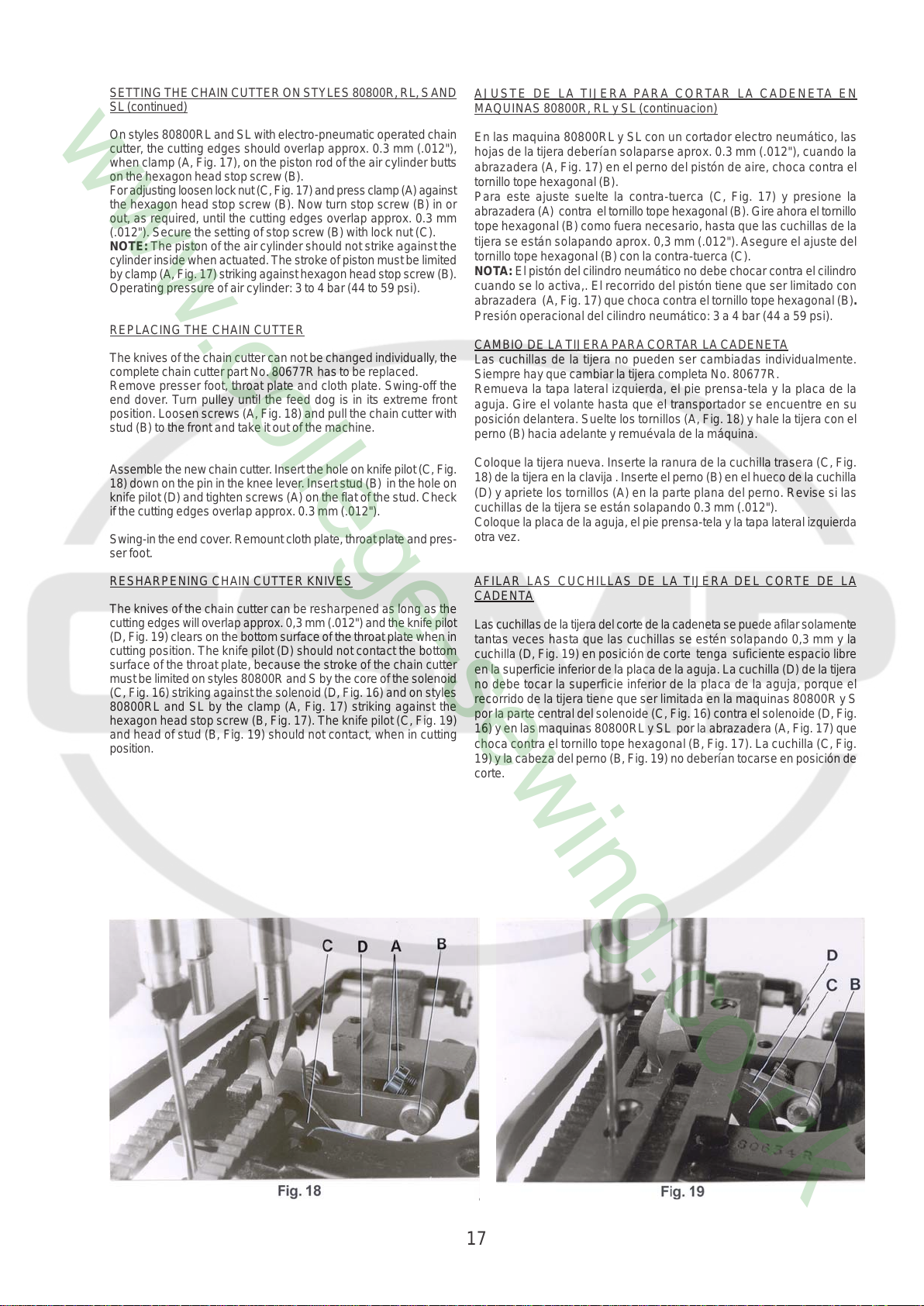
REPLACING THE CHAIN CUTTER
The knives of the chain cutter can not be changed individually, the
complete chain cutter part No. 80677R has to be replaced.
Remove presser foot, throat plate and cloth plate. Swing-off the
end dover. Turn pulley until the feed dog is in its extreme front
position. Loosen screws (A, Fig. 18) and pull the chain cutter with
stud (B) to the front and take it out of the machine.
Assemble the new chain cutter. Insert the hole on knife pilot (C, Fig.
18) down on the pin in the knee lever. Insert stud (B) in the hole on
knife pilot (D) and tighten screws (A) on the flat of the stud. Check
if the cutting edges overlap approx. 0.3 mm (.012").
Swing-in the end cover. Remount cloth plate, throat plate and pres-
ser foot.
RESHARPENING CHAIN CUTTER KNIVES
The knives of the chain cutter can be resharpened as long as the
cutting edges will overlap approx. 0,3 mm (.012") and the knife pilot
(D, Fig. 19) clears on the bottom surface of the throat plate when in
cutting position. The knife pilot (D) should not contact the bottom
surface of the throat plate, because the stroke of the chain cutter
must be limited on styles 80800R and S by the core of the solenoid
(C, Fig. 16) striking against the solenoid (D, Fig. 16) and on styles
80800RL and SL by the clamp (A, Fig. 17) striking against the
hexagon head stop screw (B, Fig. 17). The knife pilot (C, Fig. 19)
and head of stud (B, Fig. 19) should not contact, when in cutting
position.
En las maquina 80800RL y SL con un cort ador electro neumático, las
hojas de la tijera deberían solaparse aprox. 0.3 mm (.012"), cuando la
abrazadera (A, Fig. 17) en el perno del pistón de aire, choca contra el
tornillo tope hexagonal (B).
Para este ajuste suelte la contra-tuerca (C, Fig. 17) y presione la
abrazadera (A) contra el tornillo tope hexagonal (B). Gire ahora el tornillo
tope hexagonal (B) como fuera necesario, hasta que las cuchillas de la
tijera se están solapando aprox. 0,3 mm (.012"). Asegure el ajuste del
tornillo tope hexagonal (B) con la contra-tuerca (C).
NOTA: El pistón del cilindro neumático no debe chocar contra el cilindro
cuando se lo activa,. El recorrido del pistón tiene que ser limitado con
abrazadera (A, Fig. 17) que choca contra el tornillo tope hexagonal (B).
Presión operacional del cilindro neumático: 3 a 4 bar (44 a 59 psi).
CAMBIO DE LA TIJERA PARA CORTAR LA CADENETA
Las cuchillas de la tijera no pueden ser cambiadas individualmente.
Siempre hay que cambiar la tijera completa No. 80677R.
Remueva la tapa lateral izquierda, el pie prensa-tela y la placa de la
aguja. Gire el volante hasta que el transportador se encuentre en su
posición delantera. Suelte los tornillos (A, Fig. 18) y hale la tijera con el
perno (B) hacia adelante y remuévala de la máquina.
Coloque la tijera nueva. Inserte la ranura de la cuchilla trasera (C, Fig.
18) de la tijera en la clavija . Inserte el perno (B) en el hueco de la cuchilla
(D) y apriete los tornillos (A) en la parte plana del perno. Revise si las
cuchillas de la tijera se están solapando 0.3 mm (.012").
Coloque la placa de la aguja, el pie prensa-tela y la tapa lateral izquierda
otra vez.
AFILAR LAS CUCHILLAS DE LA TIJERA DEL CORTE DE LA
CADENTA
Las cuchillas de la tijera del corte de la cadeneta se puede afilar solamente
tantas veces hasta que las cuchillas se estén solapando 0,3 mm y la
cuchilla (D, Fig. 19) en posición de corte tenga suficiente espacio libre
en la superficie inferior de la placa de la aguja. La cuchilla (D) de la tijera
no debe tocar la superficie inferior de la placa de la aguja, porque el
recorrido de la tijera tiene que ser limitada en la maquinas 80800R y S
por la parte central del solenoide (C, Fig. 16) contra el solenoide (D, Fig.
16) y en las maquinas 80800RL y SL por la abrazadera (A, Fig. 17) que
choca contra el tornillo tope hexagonal (B, Fig. 17). La cuchilla (C, Fig.
19) y la cabeza del perno (B, Fig. 19) no deberían tocarse en posición de
corte.
17
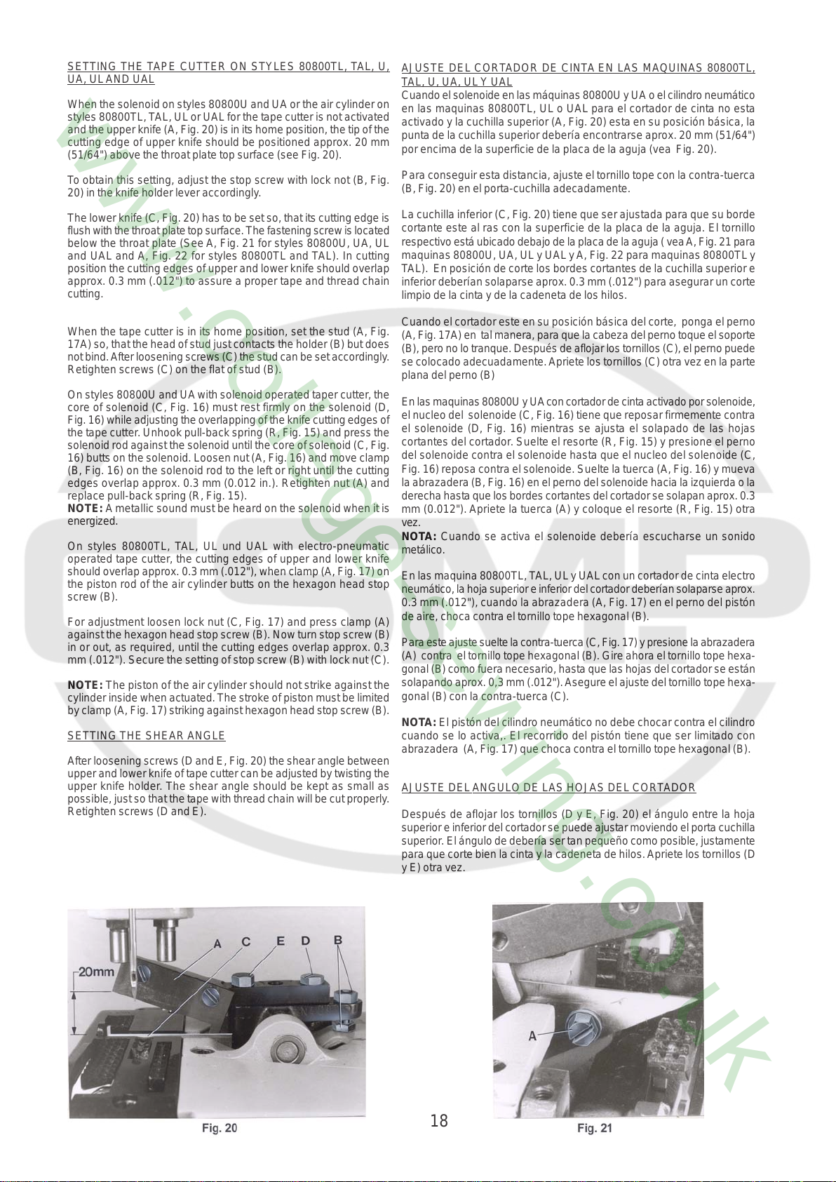
SETTING THE TAPE CUTTER ON STYLES 80800TL, TAL, U,
UA, UL AND UAL
When the solenoid on styles 80800U and UA or the air cylinder on
styles 80800TL, T AL, UL or UAL for the t ape cutter is not activated
and the upper knife (A, Fig. 20) is in its home position, the tip of the
cutting edge of upper knife should be positioned approx. 20 mm
(51/64") above the throat plate top surface (see Fig. 20).
To obtain this setting, adjust the stop screw with lock not (B, Fig.
20) in the knife holder lever accordingly.
The lower knife (C, Fig. 20) has to be set so, that its cutting edge is
flush with the throat plate top surface. The fastening screw is located
below the throat plate (See A, Fig. 21 for styles 80800U, UA, UL
and UAL and A, Fig. 22 for styles 80800TL and TAL). In cutting
position the cutting edges of upper and lower knife should overlap
approx. 0.3 mm (.012") to assure a proper tape and thread chain
cutting.
AJUSTE DEL CORTADOR DE CINTA EN LAS MAQUINAS 80800TL,
TAL, U, UA, UL Y UAL
Cuando el solenoide en las máquinas 80800U y UA o el cilindro neumático
en las maquinas 80800TL, UL o UAL para el cortador de cinta no esta
activado y la cuchilla superior (A, Fig. 20) esta en su posición básica, la
punta de la cuchilla superior debería encontrarse aprox. 20 mm (51/64")
por encima de la superficie de la placa de la aguja (vea Fig. 20).
Para conseguir esta distancia, ajuste el tornillo tope con la contra-tuerca
(B, Fig. 20) en el porta-cuchilla adecadamente.
La cuchilla inferior (C, Fig. 20) tiene que ser ajustada para que su borde
cortante este al ras con la superficie de la placa de la aguja. El tornillo
respectivo está ubicado debajo de la placa de la aguja ( vea A, Fig. 21 para
maquinas 80800U, UA, UL y UAL y A, Fig. 22 para maquinas 80800TL y
TAL). En posición de corte los bordes cort antes de la cuchilla superior e
inferior deberían solaparse aprox. 0.3 mm (.012") para asegurar un corte
limpio de la cinta y de la cadeneta de los hilos.
When the tape cutter is in its home position, set the stud (A, Fig.
17A) so, that the head of stud just contacts the holder (B) but does
not bind. After loosening screws (C) the stud can be set accordingly .
Retighten screws (C) on the flat of stud (B).
On styles 80800U and UA with solenoid operated taper cutter , the
core of solenoid (C, Fig. 16) must rest firmly on the solenoid (D,
Fig. 16) while adjusting the overlapping of the knife cutting edges of
the tape cutter. Unhook pull-back spring (R, Fig. 15) and press the
solenoid rod against the solenoid until the core of solenoid (C, Fig.
16) butts on the solenoid. Loosen nut (A, Fig. 16) and move clamp
(B, Fig. 16) on the solenoid rod to the left or right until the cutting
edges overlap approx. 0.3 mm (0.012 in.). Retighten nut (A) and
replace pull-back spring (R, Fig. 15).
NOTE: A metallic sound must be heard on the solenoid when it is
energized.
On styles 80800TL, TAL, UL und UAL with electro-pneumatic
operated tape cutter, the cutting edges of upper and lower knife
should overlap approx. 0.3 mm (.012"), when clamp (A, Fig. 17) on
the piston rod of the air cylinder butts on the hexagon head stop
screw (B).
For adjustment loosen lock nut (C, Fig. 17) and press clamp (A)
against the hexagon head stop screw (B). Now turn stop screw (B)
in or out, as required, until the cutting edges overlap approx. 0.3
mm (.012"). Secure the setting of stop screw (B) with lock nut (C).
NOTE: The piston of the air cylinder should not strike against the
cylinder inside when actuated. The stroke of piston must be limited
by clamp (A, Fig. 17) striking against hexagon head stop screw (B).
SETTING THE SHEAR ANGLE
After loosening screws (D and E, Fig. 20) the shear angle between
upper and lower knife of tape cutter can be adjusted by twisting the
upper knife holder. The shear angle should be kept as small as
possible, just so that the tape with thread chain will be cut properly .
Retighten screws (D and E).
Cuando el cortador este en su posición básica del corte, ponga el perno
(A, Fig. 17A) en tal manera, para que la cabeza del perno toque el soporte
(B), pero no lo tranque. Después de aflojar los tornillos (C), el perno puede
se colocado adecuadamente. Apriete los tornillos (C) otra vez en la parte
plana del perno (B)
En las maquinas 80800U y UA con cortador de cinta activado por solenoide,
el nucleo del solenoide (C, Fig. 16) tiene que reposar firmemente contra
el solenoide (D, Fig. 16) mientras se ajusta el solapado de las hojas
cortantes del cortador. Suelte el resorte (R, Fig. 15) y presione el perno
del solenoide contra el solenoide hasta que el nucleo del solenoide (C,
Fig. 16) reposa contra el solenoide. Suelte la tuerca (A, Fig. 16) y mueva
la abrazadera (B, Fig. 16) en el perno del solenoide hacia la izquierda o la
derecha hasta que los bordes cortantes del cortador se solapan aprox. 0.3
mm (0.012"). Apriete la tuerca (A) y coloque el resorte (R, Fig. 15) otra
vez.
NOTA: Cuando se activa el solenoide debería escucharse un sonido
metálico.
En las maquina 80800TL, T AL, UL y UAL con un cortador de cinta electro
neumático, la hoja superior e inferior del cortador deberían solaparse aprox.
0.3 mm (.012"), cuando la abrazadera (A, Fig. 17) en el perno del pistón
de aire, choca contra el tornillo tope hexagonal (B).
Para este ajuste suelte la contra-tuerca (C, Fig. 17) y presione la abrazadera
(A) contra el tornillo tope hexagonal (B). Gire ahora el tornillo tope hexa-
gonal (B) como fuera necesario, hasta que las hojas del cortador se están
solapando aprox. 0,3 mm (.012"). Asegure el ajuste del tornillo tope hexa-
gonal (B) con la contra-tuerca (C).
NOTA: El pistón del cilindro neumático no debe chocar contra el cilindro
cuando se lo activa,. El recorrido del pistón tiene que ser limitado con
abrazadera (A, Fig. 17) que choca contra el tornillo tope hexagonal (B).
AJUSTE DEL ANGULO DE LAS HOJAS DEL CORTADOR
Después de aflojar los tornillos (D y E, Fig. 20) el ángulo entre la hoja
superior e inferior del cortador se puede ajustar moviendo el porta cuchilla
superior. El ángulo de debería ser tan pequeño como posible, justamente
para que corte bien la cinta y la cadeneta de hilos. Apriete los tornillos (D
y E) otra vez.
18
 Loading...