

INSTRUCTIONS AND ILLUSTRATED P ARTS MANUAL
INSTRUCCIONES Y LISTA ILUSTRADA DE P ARTES
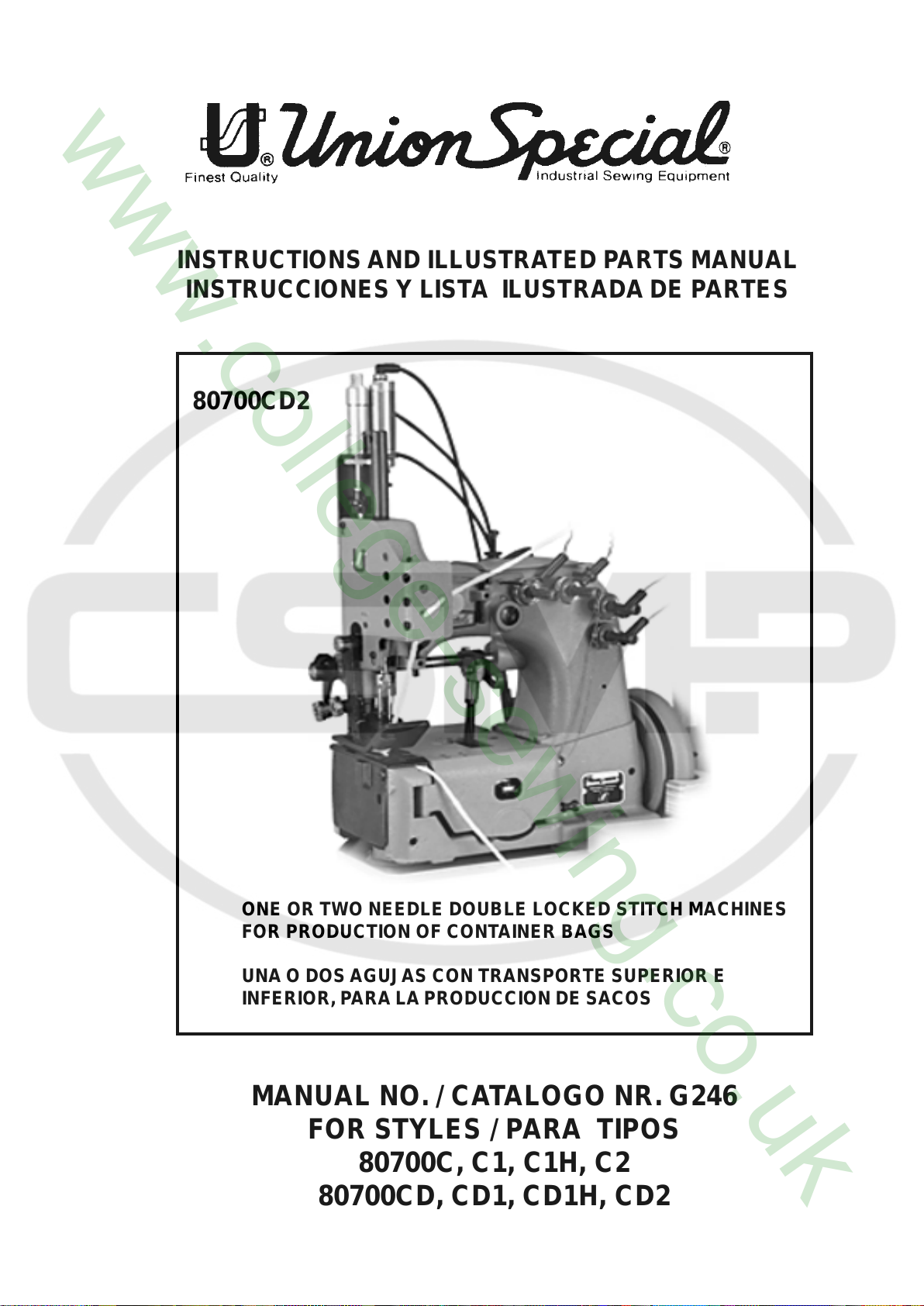
80700CD2
ONE OR TWO NEEDLE DOUBLE LOCKED STITCH MACHINES
FOR PRODUCTION OF CONTAINER BAGS
UNA O DOS AGUJAS CON TRANSPORTE SUPERIOR E
INFERIOR, P ARA LA PRODUCCION DE SACOS
MANUAL NO. / CATALOGO NR. G246
FOR STYLES / PARA TIPOS
80700C, C1, C1H, C2
80700CD, CD1, CD1H, CD2
MANUAL NO. G246
INSTRUCTIONS AND ILLUSTRATED PARTS
LIST FOR 80700 SERIES MACHINES
INSTRUCCIONES Y LISTA DE PARTES
CATALOGO NR. G246
ILUSTRADAS MODELOS SERIE 80700
Fourth Edition Copyright 2002
Union Special GmbH Rights Reserved in All
PREFACE
This catalog has been prepared to guide you while
operating 80700 series machines and arranged to simplify
ordering spare parts.
This catalog explains in detail the proper settings for
operation of the machines. Illustrations are used to show
the adjustments and reference letters are used to point
out specific items discussed.
Careful attention to the instructions and cautions for
operating and adjusting these machines will enable you
to maintain the superior performance and reliability
designed and built into every Union Special bag sewing
machine.
Adjustments and cautions are presented in sequence so
that a logical progression is accomplished. Some
adjustments performed out of sequence may have an
adverse effect on the function of the other related parts.
Printed in Germany
by
Countries
Union Special GmbH Derechos Reservados
INTRODUCCION
Este manual fue preparado para guiar al usuario en la
operación de maquinas de la serie 80700 y ayudar para
simplificar la elaboración de los pedidos de los repuestos.
Este manual explica detalladamente los ajustes para la
operación de la maquina. Las ilustraciones sirven para
demostrar los ajustes y las letras en referencia indican
los puntos específicos discutidos.
Una cuidadosa atención a las instrucciones y las
precauciones operando y ajustando estas maquinas le
va a permitir mantener el mejor funcionamiento y la
confiabilidad que caracteriza las maquinas cerradoras
de sacos de Union Special.
Los ajustes y precauciones son presentados en
secuencia para que se consiga una progresión lógica.
La ejecución de algunos ajustes fuera de la secuencia
puede causar un efecto adverso para el funcionamiento
de otras partes relacionadas.
Cuarta Edición © 2002
en todos los paises del mundo
Impreso en Alemania
This manual has been comprised on the basis of available
information. Changes in design and / or improvements
may incorporate a slight modification of configuration in
illustrations or cautions.
On the following pages will be found illustrations and
terminology used in describing the instructions and the
parts for your machine.
In addition to the instructions and to the mandatory rules
and regulations for accident prevention and environmental
protection in the country and place of use of the machine
/ unit, the generally recognized technical rules for safe
and proper working must also be observed.
The instructions are to be supplemented by the respective
national rules and regulations for accident prevention and
environmental protection.
Este manual se comprende a base de la información
actual. Cambios en diseño y/o mejoras pueden significar
leves modificaciones de la configuración de las
ilustraciones o precauciones.
En las paginas siguientes se encuentran ilustraciones y
terminologías usadas en la descripción de las
instrucciones y las piezas de la maquina.
Adicionalmente a las instrucciones, las reglas y
regulaciones obligatorias para prevenir accidentes y la
protección ambiental del país y lugar donde se encuentra
la maquina/unidad, hay que considerar las reglas
técnicas para un trabajo seguro y adecuado.
Las instrucciones hay que complementarlas con las
respectivas reglas y regulaciones nacionales contra
accidentes y protección del ambiente.
2
TABLE OF CONTENTS
INDICE
PAGE / PAGINA
4-5
5
SAFETY RULES
REGLAS DE SEGURIDAD
IDENTIFICATION OF MACHINES
IDENTIFICACION DE LAS MAQUINAS
APPLICATION OF THIS INSTRUCTION MANUAL
APLICACION DE ESTE MANUAL DE INSTRUCCIONES
STYLES OF MACHINES
ESTILOS DE MAQUINAS
INSTALLATION, LUBRICATING
INSTALACION, LUBRICACION
NEEDLES
AGUJAS
THREADING DIAGRAMS
DIAGRAMAS DE ENHEBRADO
OPERATING INSTRUCTIONS
INSTRUCCIONES DE OPERACION
INSTRUCTION FOR ENGINEERS
INSTRUCCIONES PARA LOS MECANICOS
ORDERING WEAR AND SPARE PARTS
INSTRUCCIONES PARA LOS PEDIDOS DE REPUESTOS
EXPLODED VIEWS AND DESCRIPTION OF PARTS
DIBUJOS Y DESCRIPCION DE LOS REPUESTOS
BUSHINGS AND OILING PARTS
BOCINAS Y PARTES DE LUBRICACION
CLOTH PLATES AND MISCELLANEOUS COVERS
TAPA DE LA CAMA Y OTRAS TAPAS
THREAD TENSION, THREAD GUIDES AND NEEDLE BAR GUARD FOR 80700 C, C1, C1H, C2
TENSION DEL HILO, GUIA HILOS Y PROTECTOR DE LA BARRA DE AGUJA PARA 80700 C, C1, C1H, C2
THREAD TENSION, THREAD GUIDES AND NEEDLE BAR GUARD FOR 80700 CD, CD1, CD1H, CD2
TENSION DEL HILO, GUIA HILOS Y PROTECTOR DE LA BARRA DE AGUJA PARA 80700 CD, CD1, CD1H, CD2
NEEDLE LEVER
PALANCA DE ACCIONAMIENTO DE LA BARRA DE AGUJA
NEEDLE BAR, NEEDLE LEVER LINK, CRANK SHAFT, PULLEY, LOOPER DRIVE AND LOOPER AVOID ECCENTRIC
BARRAS DE LA AGUJA, JUNTAS PARA LEVANTAR LA AGUJA, EJE PRINCIPAL, VOLANTE, EXCENTRICA.S DEL
ACCIONAMIENTO DEL LOOPER Y DE LA DESVIACION DEL LOOPER
LOOPER AVOID ECCENTRIC FORK, LOOPER LEVER AND ROCKER; LOOPER THREAD CAST-OFF
HORQUILLA PARA LA EXCENTRICA DE LA ESQUIVA DEL LOOPER, LOOPER, PALANCAS DEL LOOPER Y DEL
ACCIONAMIENTO DEL LOOPER, ALIMENTADOR DEL HILO DEL LOOPER
FEED MECHANISM
MECANISMO DE TRANSPORTE
UPPER FEED DRIVE MECHANISM
MECANISMO DE TRANSPORTE SUPERIOR
PRESSER BAR, PRESSER BAR SPRINGS AND PRESSER FOOT LIFTER LEVER
BARRAS DEL PIE PRENSATELA, MUELLES PARA LAS BARRAAS DEL PIE PRENSATELA Y LEVANTADOR DEL PIE
PRENSATELA
PNEUMATIC-PARTS FOR PRESSER FOOT LIFTER
PIEZAS DEL SISTEMA NEUMATICO PARA LEVANTAR EL PIE PRENSA TELA
THREAD CHAIN CUTTERS
CORTADOR DE CADENETA
SEWING PARTS, STYLE 80700 C, C1, C1H, C2
PIEZAS DE FORMACION DE COSTURA, MODELOS 80700 C, C1, C1H, C2
SEWING PARTS, STYLE 80700 CD
PIEZAS DE FORMACION DE COSTURA, MODELO80700 CD
SEWING PARTS, STYLE 80700 CD1, CD1H
PIEZAS DE FORMACION DE COSTURA, MODELO80700 CD1, CD1H
SEWING PARTS, STYLE 80700 CD2
PIEZAS DE FORMACION DE COSTURA, MODELO80700 CD2
ACCESSORIES
ACCESORIOS
NUMERICAL INDEX OF PARTS
INDICE NUMERICO DE LOS REPUESTOS
5
6 -7
8 - 17
17
18 - 19
20 - 21
22 - 29
30
31
32 - 33
34 - 35
36 - 37
38 - 39
40 - 41
42 - 43
44 - 45
46 - 47
48 - 49
50 - 51
52 - 55
56 - 67
68 - 69
70 - 71
72 - 73
74 - 75
76 - 79
80 - 82
3
9. Maintenance, repair and conversion work (see item 8)
must be done only by trained technicians or special
skilled personnel under condsideration of the
instructions.
Only genuine spare parts approved by UNION
SPECIAL have to be used for repairs. These parts are
designed specifically for your machine and
manufactured with utmost precision to assure long
lasting service.
10. Any work on the electrical equipment must be done by
an electrician or under direction and supervision of
special skilled personnel.
11. Work on parts and equipment under electrical power
is not permitted. Permissible exceptions are described
in the applicable section of standard sheet EN 50 110
/ VDE 0105.
12. Before doing maintenance and repair work on the
pneumatic equipment, the machine has to be
disconnected from the compressed air supply. In
case of existing residual air pressure after
disconnecting from compressed air supply (e.g.
pneumatic equipment with air tank), the pressure has
to be removed by bleeding. Exceptions are only
allowed for adjusting work and function checks done
by special skilled personnel.
9. Mantenimiento, reparaciones y trabajos de conversión
(vease No. 8) solamente pueden ser efectuados por
técnicos entrenados o personal especializado bajo
consideración de las instrucciones.
Solamente repuestos originales y aprobados por
Union Special pueden ser utilizados para
reparaciones.Estos repuestos han sido diseñados
especificamente para estas máquinas, con precisión
y para asegurar su máxima vida útil.
10. Cualquier trabajo con el equipo eléctrico tiene que ser
ejecutado por un electricista o bajo la supervisión de
personal especialmente entrenado.
11. No esta permitido trabajar en piezas y equipos con la
electricidad conectada. Excepciones permitidas están
descritas en EN 50110 / VDE 0105.
12. Antes de hacer mantenimiento o reparaciones del
equipo neumático, hay que desconectar la maquina
de la alimentación del aire comprimido. En el caso
que exista una presión de aire residual después de
desconectar la maquina (por ejemplo equipos con
tanques de aire), la presión tiene que ser eliminada
abriendo las válvulas. Excepciones están solamente
permitidas para trabajos de ajuste y revisión de
funciones por personal especialmente entrenado.
IDENTIFICATION OF MACHINES
Each UNION SPECIAL machine is identified by a Style
number, which on this Class machine, is stamped into
the Style plate affixed to the right front of machine. Serial
number is stamped into bed casting at the right front base
of machine.
APPLICATION OF THIS INSTRUCTION
MANUAL
NOTE: Instructions stating direction or location such
as right left, front or rear of machine, are given
relative to operator’s position at the machine,
unless otherwise noted.
The handwheel pulley rotates clockwise, in
operating direction, when viewed from the right
end of machine.
CAUTION! Before putting into service check the
direction of rotation. Breakage may occur
when the direction of rotation is wrong.
IDENTIFICACION DE LAS MAQUINAS
Cada máquina UNION SPECIAL está identificada por
un número de estilo, el cual está estampado en la
placa fijada a la máquina. El número de serial está
troquelado en la carcasa de la máquina.
APLICACIONES DE ESTE MANUAL DE
INSTRUCCIONES
NOTA: Instrucciones que se refieren a direcciones y
posiciones como derecho, izquierdo, adelante o
atrás se entienden desde el punto de vista de un
operador sentado enfrente de la máquina, si no
esta notificado diferente. El manubrio del volante
gira en sentido del reloj, en su dirección de
operación, cuando es visto desde la parte
derecha del final de la maquina.
PRECAUCION: Revise antes de poner la máquina en
marcha el sentido de la rotación. El
sentido de rotación equivocado puede
causar roturas.
5
80700CD: Two needle independent row, double locked
chainstitch machine for even matched seaming of
container bags and simultaneously attaching belt bands.
Its design and pedestal installation makes it especially
suitable for attaching filling and discharging tubes and
inserting top covers.
Guides for fillter cord from the top and / or from below
for sealing the needle punctures of the left needle.
Mechanically driven built-in thread chain cutter.
When removing one needle, the machine can be operated
as a single needle machine.
80700 CD: Máquina de dos agujas con dos costuras
independientes de cadeneta doble para coser sin peligro de
desplazamiento de pliegos los sacos contenedores fijando
al mismo tiempo las correas. Debido a su diseño y montaje
en pedestal, la máquina está especialmente apta para fijar
los embudos de carga y descarga al saco y la colocación de
las tapas. La aguja izquierda de la máquina está equipada
con una guía superior e inferior de los cordeles para sellar
las perforaciones de las agujas desde arriba y/o desde abajo.
Quitando una aguja, la máquina se puede utilizar como
máquina de una sola aguja.
Seam specification: (401.401) SSa-2
Needle distance: 7,2 mm (18 ga)
Sewing capacity: up to 14 mm (35/64 in.)
Standard needle: 9848G300/120
Stitch range: 6 to 10 mm (2 to 4 SPI)
Standard setting: 10 mm
Working diameter of
handwheel pulley: 150 mm (5 29/32 in.)
Speed: up to 1400 stitches per minute,
depending on thread, fabric and
sewing operation.
Equivalent continous A-weighted sound pressure level at
workstations at the operating speed
1400 RPM: 75 dB (A)
Noise measurement according DIN 45635-48 / ISO 10821
Weight net: 42 kg
80700CD1: Same as 80700CD, but with enlarged sewing
parts and built-in pneumatically operated thread chain
cutter.
Built-in electro-pneumatically operated presser foot and
upper feed dog lifter.
Pneumatic presser foot spring.
Sewing capacity: up to 18 mm
Stitch range: 6 - 12 mm
80700CD1H: Same as 80700CD1, but with electro-
pneumatically operated hot thread chain cutter.
Especificación de la costura: (401.401) Ssa-2
Distancia entre agujas: 7,2 mm
Ancho de la costura: 10 – 25 mm
Capacidad de costura: hasta 14 mm
Aguja: 9848G 300/120
Largo de la puntada: 6 – 10 mm
Largo de la puntada standard: 10 mm
Diámetro efectivo del volante: 150 mm
Revoluciones: hasta 1400 puntadas/
minuto, dependiendo de
los hilos, material y
operación.
Nivel de ruido de la unidad referente al puesto de trabajo
con una velocidad de 1400 RPM 75dB (A)
Medición según DIN 45635-48 / ISO 10821
Peso, neto 42 kgs
80700 CD-1: igual que 80700 CD, pero equipada con un
cortador de cadeneta accionado neumáticamente y con
sistema de presión y levantamiento neumático del transporte
superior.
Capacidad de costura: hasta 18 mm
Largo de la puntada: 6 – 12 mm
80700CD1H: Igual a 80700CD1, pero con un cortador
caliente de cadeneta electroneumático, incorporado.
Pié prensatelas con resorte neumático.
80700CD2: Same as 80700CD1, but without any chain
cutter.
Working pressure when using a Union Special installation
with electro-pneumatically operated presser foot and upper
feed dog lifter: 4 bar (58 PSI)
Air consumption: 10 Nl/min (0,3 cu.ft./min.)
Use Union Special installations for the described sewing
machines. Union Special sewing tables and pedestals
complete the particular sewing machine to a sewing unit
and guarantee safe operation as well as the indicted data
of the sound presser level generated by the sewing unit.
80700 CD-2: igual a 80700CD-1, sin cortador de cadeneta.
Presión de trabajo utilizando un montaje original de UNION
SPECIAL con levantador electro-neumático de pie prensa-
tela y transporte superior: 4 bar
Consumo de aire comprimido: 10 Nl/minuto (0,3 cu. Ft./
min)
Utilize montajes de UNION SPECIAL para las máquinas
descritas. Mesas y pedestales de UNION SPECIAL
complementan las máquinas de coser a una unidad de coser
y garantizan una operación segura y los niveles de ruido.
7
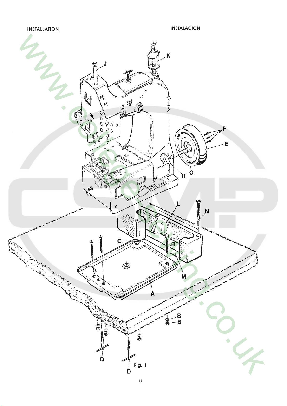
INSTALLATION
INSTALACION
Fig. 1
8
INSTALLATION (continued)
INSTALACION (Continuación)
1. Unpack the sewing machine and the accessories.
2. Mount the base plate (A, Fig. 1) with four screws,
nuts and washers (B) in the provided holes on the
table board.
3. Place the sewing machine on the base plate so that
the roll pin (C) in the base plate engages with the
right rear hole in the machine base.
4. Fasten the sewing machine with the two T-screws (D)
on the base plate.
5. Place the V-belt, supplied with the sewing table, on
the handwheel pulley .
6. Assemble the handwheel pulley (E) with three
countersunk screws (F) to the sewing machine. Pin
(G) must engage with the hole in hub (H).
7. Screw in needle bar guard (J).
8. Screw in sight feed oiler (K).
9. Align the handwheel belt guard (L) with the V-belt slot
(M) in the table board and with the handwheel pulley
and fasten it with two wood screws (N) on the table
board.
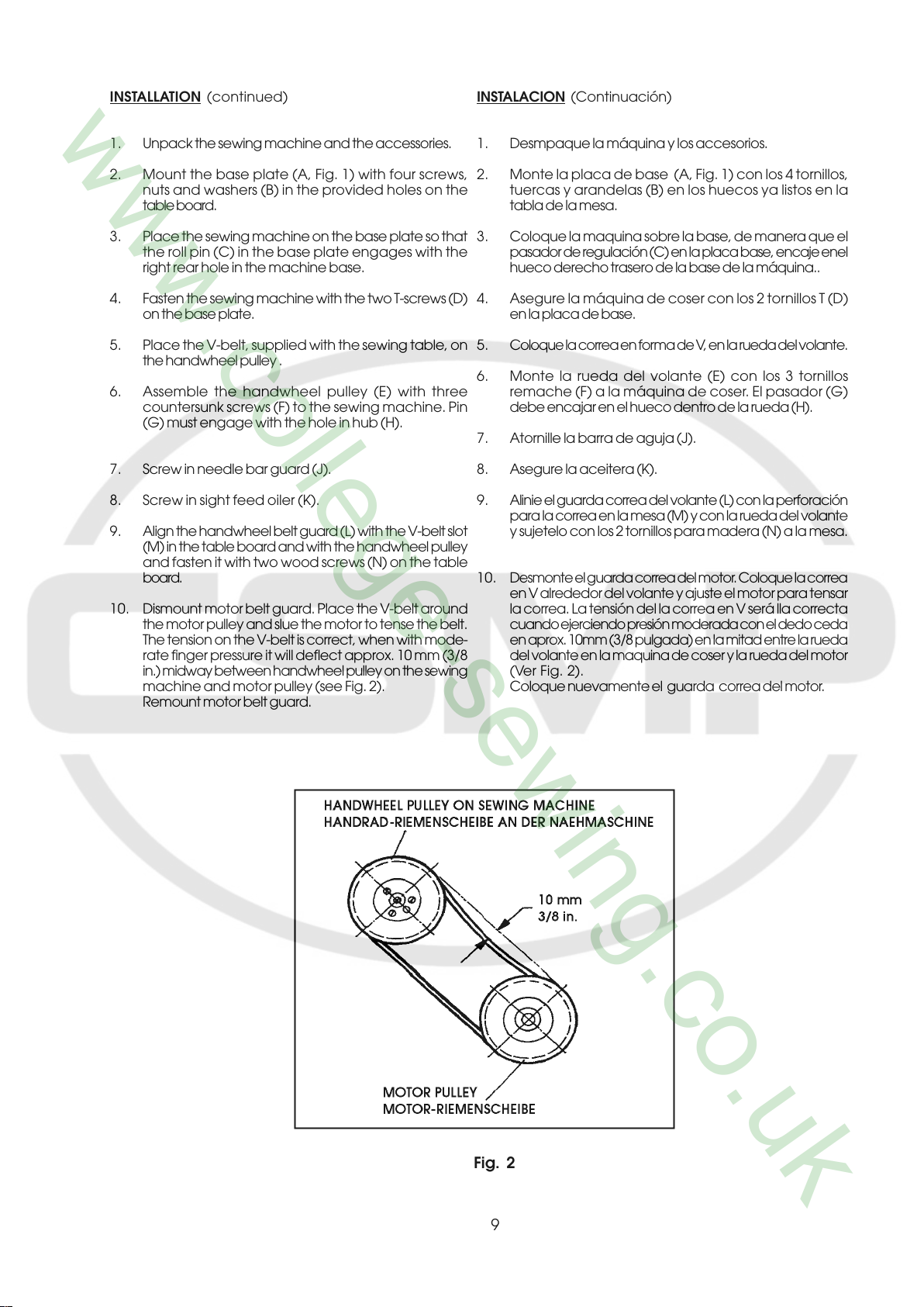
10. Dismount motor belt guard. Place the V-belt around
the motor pulley and slue the motor to tense the belt.
The tension on the V-belt is correct, when with mode-
rate finger pressure it will deflect approx. 10 mm (3/8
in.) midway between handwheel pulley on the sewing
machine and motor pulley (see Fig. 2).
Remount motor belt guard.
1. Desmpaque la máquina y los accesorios.
2. Monte la placa de base (A, Fig. 1) con los 4 tornillos,
tuercas y arandelas (B) en los huecos ya listos en la
tabla de la mesa.
3. Coloque la maquina sobre la base, de manera que el
pasador de regulación (C) en la placa base, encaje enel
hueco derecho trasero de la base de la máquina..
4. Asegure la máquina de coser con los 2 tornillos T (D)
en la placa de base.
5 . Coloque la correa en forma de V, en la rueda del volante.
6. Monte la rueda del volante (E) con los 3 tornillos
remache (F) a la máquina de coser. El pasador (G)
debe encajar en el hueco dentro de la rueda (H).
7. Atornille la barra de aguja (J).
8. Asegure la aceitera (K).
9. Alinie el guarda correa del volante (L) con la perforación
para la correa en la mesa (M) y con la rueda del volante
y sujetelo con los 2 tornillos para madera (N) a la mesa.
10 . Desmonte el guarda correa del motor. Coloque la correa
en V alrededor del volante y ajuste el motor para tensar
la correa. La tensión del la correa en V será lla correcta
cuando ejerciendo presión moderada con el dedo ceda
en aprox. 10mm (3/8 pulgada) en la mitad entre la rueda
del volante en la maquina de coser y la rueda del motor
(Ver Fig. 2).
Coloque nuevamente el guarda correa del motor.
Fig. 2
9
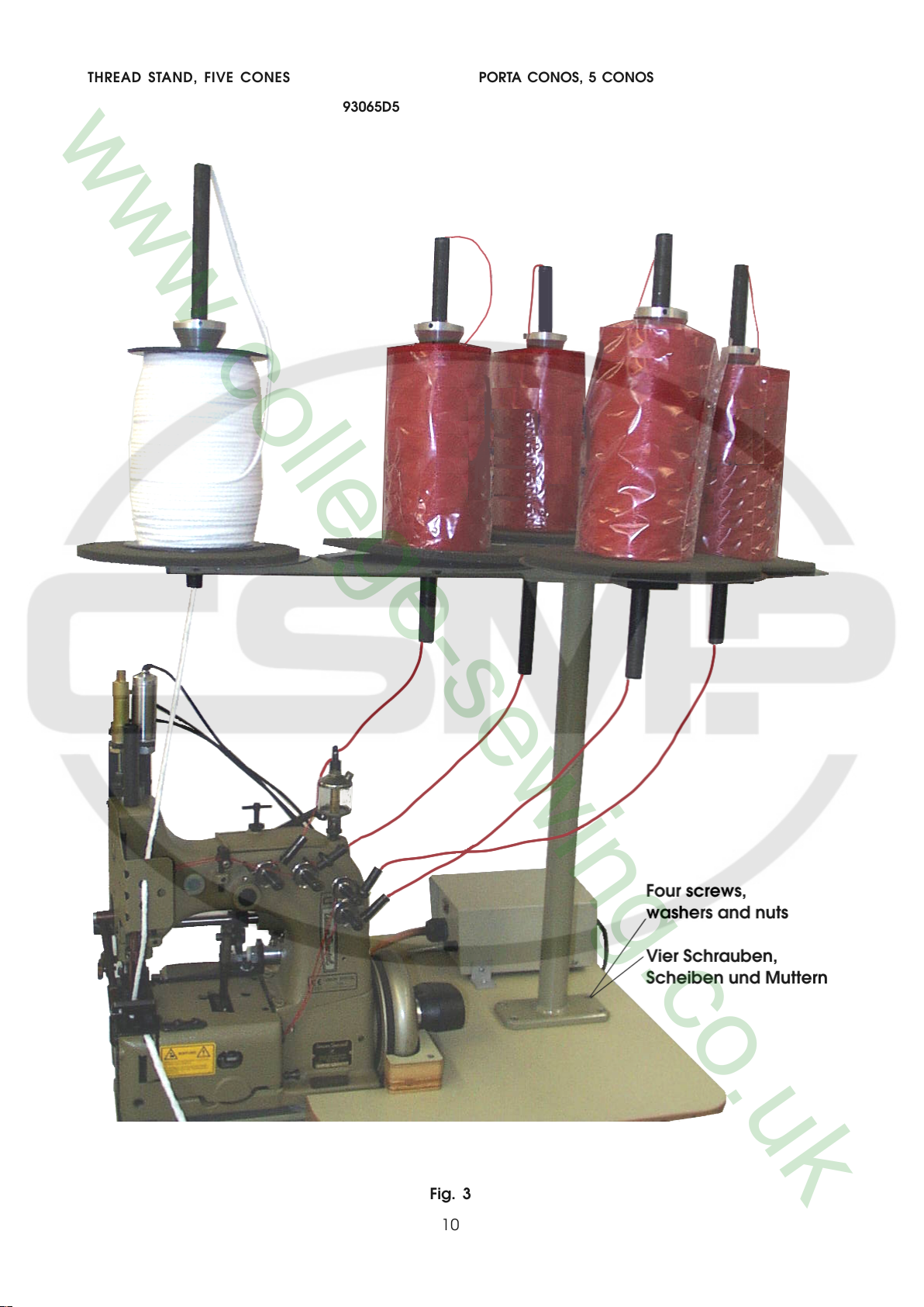
THREAD STAND, FIVE CONES PORTA CONOS, 5 CONOS
93065D5
Fig. 3
10
INSTALLATION (continued) INSTALACION (Continuación)
11. Hook the lifter chain to the lifter lever of the sewing
machine and to the small treadle on the sewing table.
12. Mount the thread stand base with four screws on the
right side of the table board and assemble the thread
stand as shown in Fig. 3, see also pages 76 to 77.
13 . Check the direction of rotation. The handwheel pulley
must rotate clockwise (to the right), when viewed from
the right end of the machine.
Switch on the motor. Only shortly and very slightly
depress the motor treadle and check the direction of
rotation. Immediately release the treadle. Switch off
and wait until the motor has stopped.
CAUTION! In case the direction of rotation has to
be changed, the reversing of the polarity
is only allowed to be done by a skilled
electrician.
11. Enganche la cadena levantadora a la palanca
levantadora de la máquina de coser y al puqueño pedal
en la mesa de la mñquina de coser.
12. Asegure la base del porta conos con los cuatro tornillos
al lado derecho de la mesa de la máquina de coser y
monte el porta conos como se enseña en la Fig. 3. Vea
tambien las páginas 76 y 77.
13. Verifique la dirección de rotación. El volante debe girar
en dirección del reloj (a la derecha), cuando es visto
desde la parte derecha de la máquina.
Encienda el motor. Presione ligeramente el pedal y
chequee la dirección de rotación. Sueltelo
inmediatamente. Apague el motor y espere hasta que
se detenga totalmente.
PRECAUCION En el caso que la dirección de rotación deba
ser cambiada, la reversión de la polaridad
debe ser realizada por un electricista
calificado.
11
Fig. 4
12
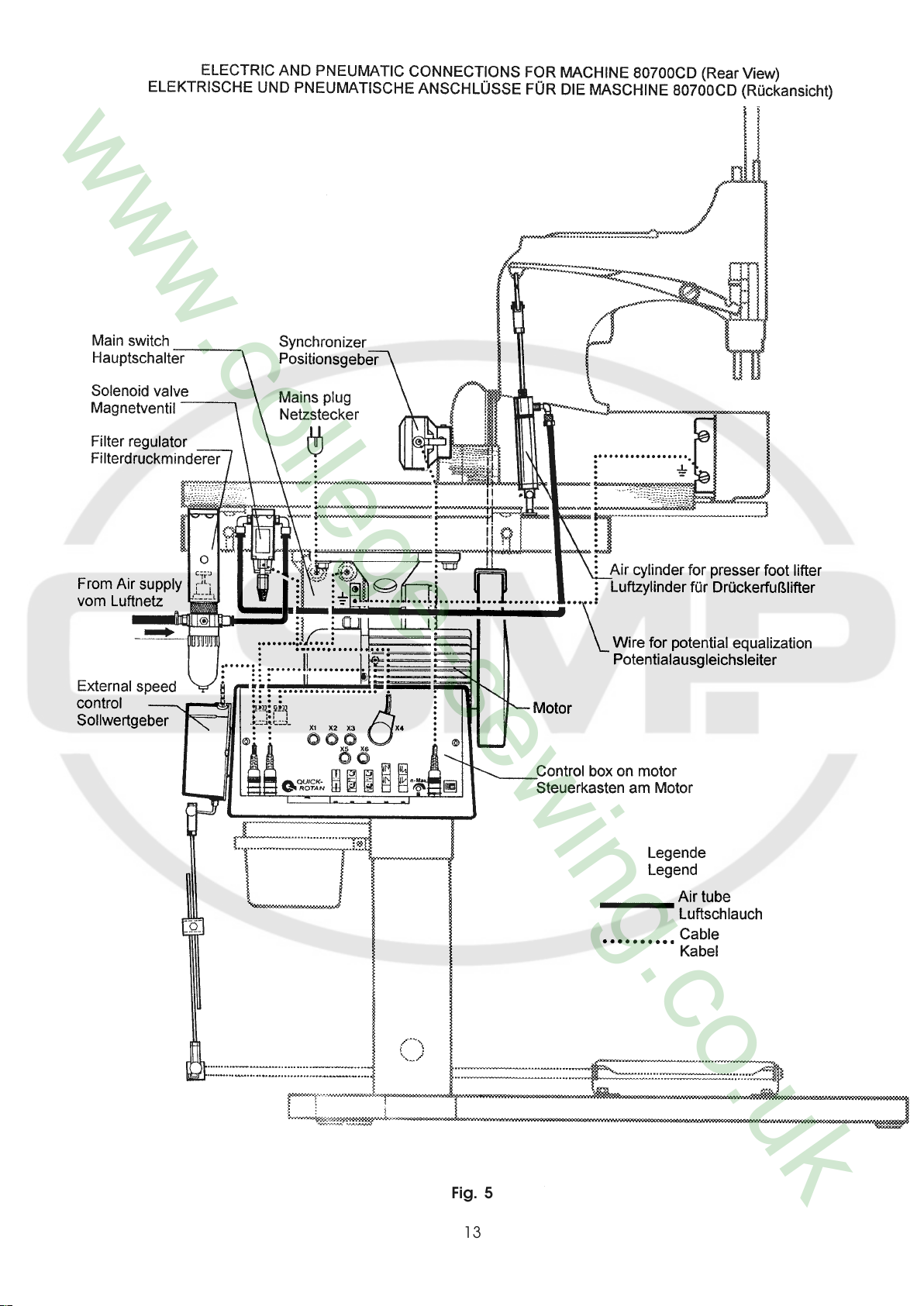
Fig. 5
13
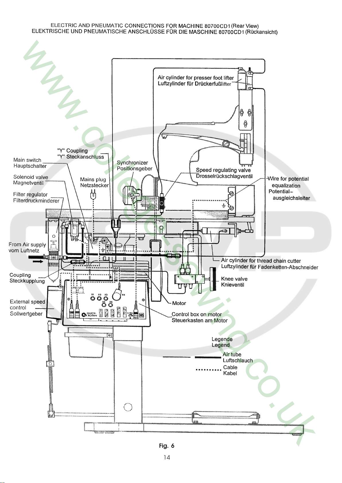
Fig. 6
14
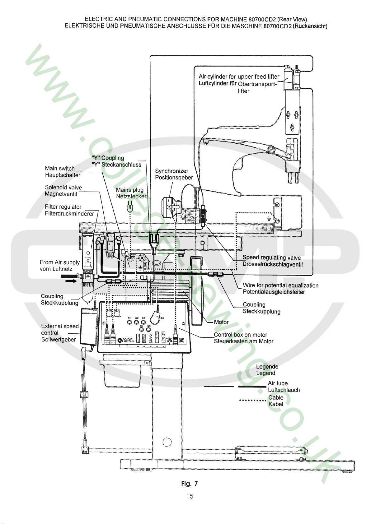
Fig. 7
15
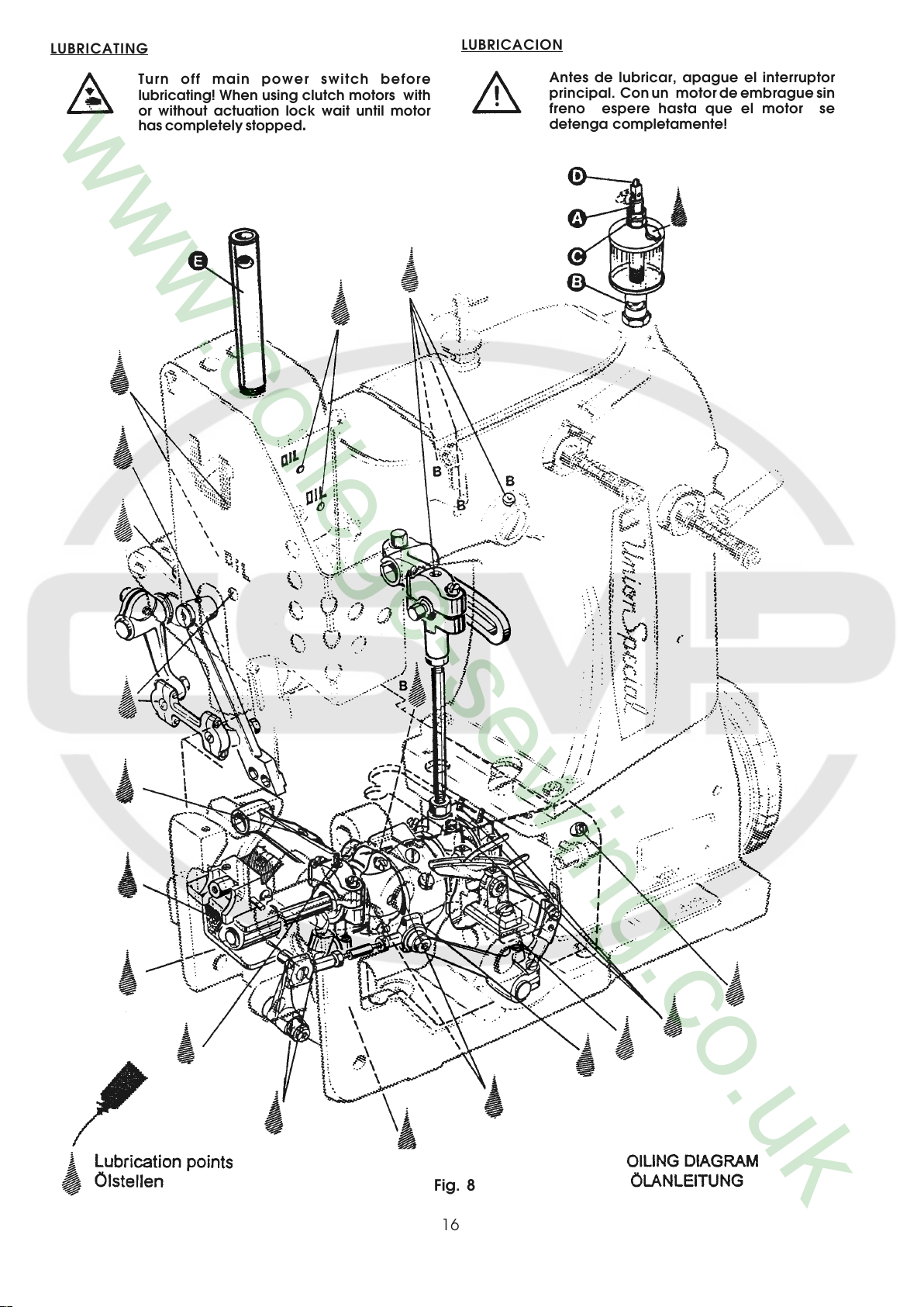
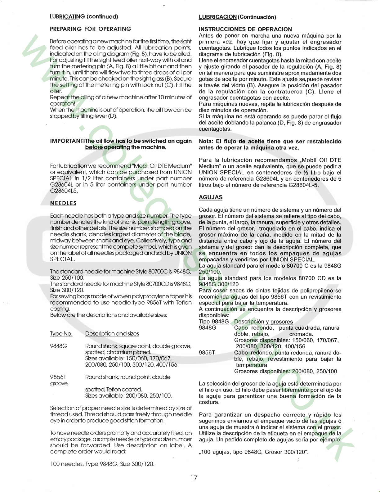
LUBRICATING
LUBRICACION
Turn off main power switch before
lubricating! When using clutch motors with
or without actuation lock wait until motor
has completely stopped.
Antes de lubricar, apague el interruptor
principal. Con un motor de embrague sin
freno espere hasta que el motor se
detenga completamente!
Fig. 8
16
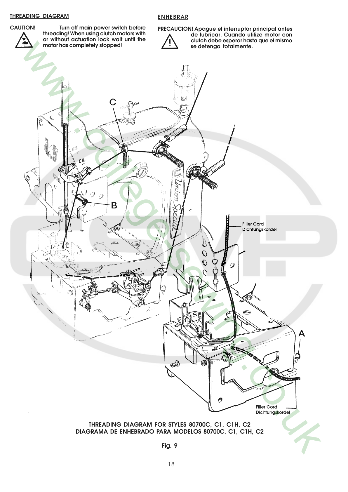
THREADING DIAGRAM
ENHEBRAR
CAUTION! Turn off main power switch before
threading! When using clutch motors with
or without actuation lock wait until the
motor has completely stopped!
PRECAUCION! Apague el interruptor principal antes
de lubricar. Cuando utilize motor con
clutch debe esperar hasta que el mismo
se detenga totalmente.
THREADING DIAGRAM FOR STYLES 80700C, C1, C1H, C2
DIAGRAMA DE ENHEBRADO PARA MODELOS 80700C, C1, C1H, C2
Fig. 9
18
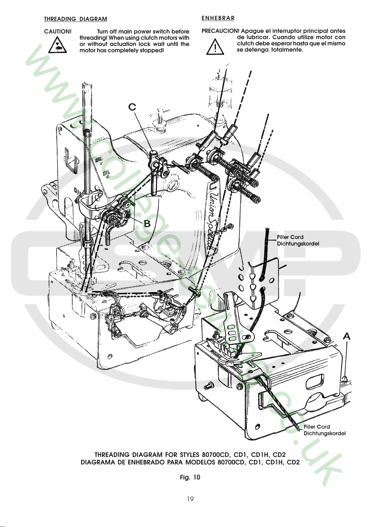
THREADING DIAGRAM
ENHEBRAR
CAUTION! Turn off main power switch before
threading! When using clutch motors with
or without actuation lock wait until the
motor has completely stopped!
PRECAUCION! Apague el interruptor principal antes
de lubricar. Cuando utilize motor con
clutch debe esperar hasta que el mismo
se detenga totalmente.
THREADING DIAGRAM FOR STYLES 80700CD, CD1, CD1H, CD2
DIAGRAMA DE ENHEBRADO PARA MODELOS 80700CD, CD1, CD1H, CD2
Fig. 10
19
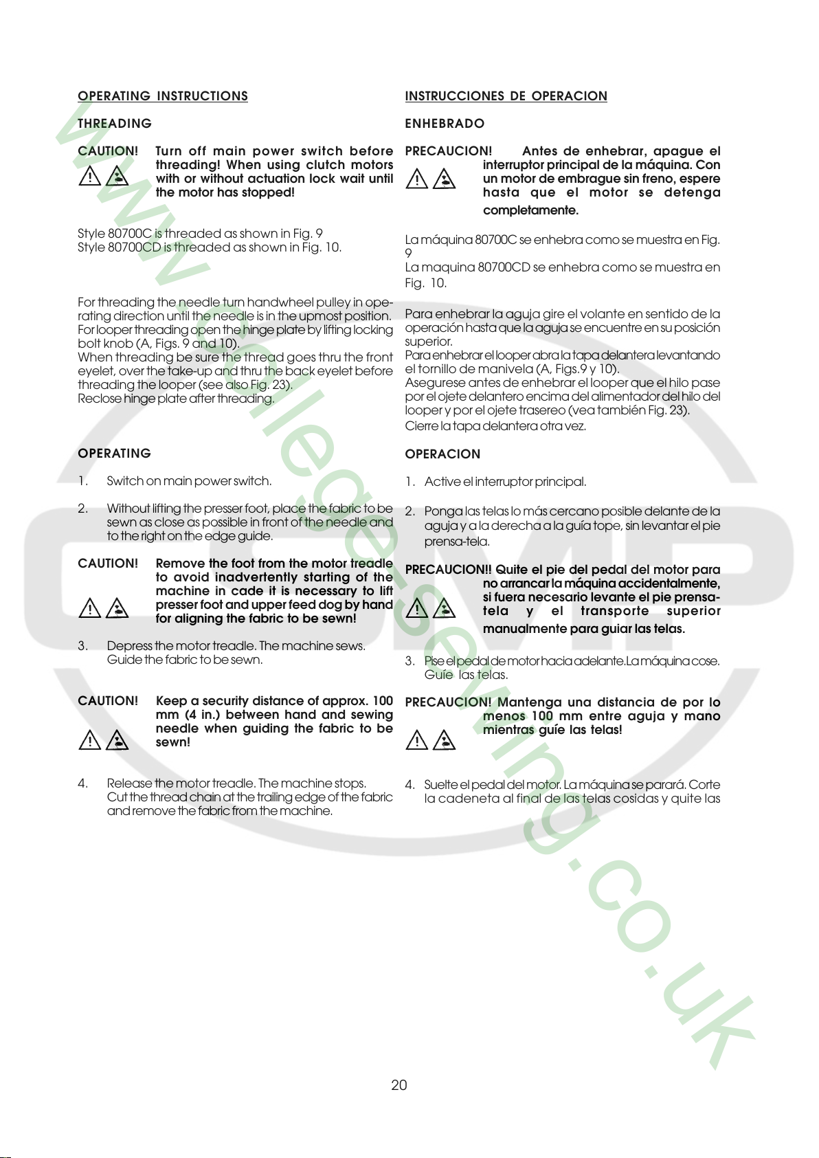
OPERATING INSTRUCTIONS
INSTRUCCIONES DE OPERACION
THREADING
CAUTION! Turn off main power switch before
Style 80700C is threaded as shown in Fig. 9
Style 80700CD is threaded as shown in Fig. 10.
For threading the needle turn handwheel pulley in ope-
rating direction until the needle is in the upmost position.
For looper threading open the hinge plate by lifting locking
bolt knob (A, Figs. 9 and 10).
When threading be sure the thread goes thru the front
eyelet, over the take-up and thru the back eyelet before
threading the looper (see also Fig. 23).
Reclose hinge plate after threading.
OPERATING
1. Switch on main power switch.
2. Without lifting the presser foot, place the fabric to be
sewn as close as possible in front of the needle and
to the right on the edge guide.
CAUTION! Remove the foot from the motor treadle
3. Depress the motor treadle. The machine sews.
Guide the fabric to be sewn.
threading! When using clutch motors
with or without actuation lock wait until
the motor has stopped!
to avoid inadvertently starting of the
machine in cade it is necessary to lift
presser foot and upper feed dog by hand
for aligning the fabric to be sewn!
ENHEBRADO
PRECAUCION! Antes de enhebrar, apague el
interruptor principal de la máquina. Con
un motor de embrague sin freno, espere
hasta que el motor se detenga
completamente.
La máquina 80700C se enhebra como se muestra en Fig.
9
La maquina 80700CD se enhebra como se muestra en
Fig. 10.
Para enhebrar la aguja gire el volante en sentido de la
operación hasta que la aguja se encuentre en su posición
superior.
Para enhebrar el looper abra la tapa delantera levantando
el tornillo de manivela (A, Figs.9 y 10).
Asegurese antes de enhebrar el looper que el hilo pase
por el ojete delantero encima del alimentador del hilo del
looper y por el ojete trasereo (vea también Fig. 23).
Cierre la tapa delantera otra vez.
OPERACION
1. Active el interruptor principal.
2. Ponga las telas lo más cercano posible delante de la
aguja y a la derecha a la guía tope, sin levantar el pie
prensa-tela.
PRECAUCION!! Quite el pie del pedal del motor para
no arrancar la máquina accidentalmente,
si fuera necesario levante el pie prensa-
tela y el transporte superior
manualmente para guiar las telas.
3 . Pise el pedal de motor hacia adelante.La máquina cose.
Guíe las telas.
CAUTION! Keep a security distance of approx. 100
mm (4 in.) between hand and sewing
needle when guiding the fabric to be
sewn!
4. Release the motor treadle. The machine stops.
Cut the thread chain at the trailing edge of the fabric
and remove the fabric from the machine.
PRECAUCION! Mantenga una distancia de por lo
menos 100 mm entre aguja y mano
mientras guíe las telas!
4. Suelte el pedal del motor. La máquina se parará. Corte
la cadeneta al final de las telas cosidas y quite las
20
CHANGING THE NEEDLE(S)
CAMBIO DE AGUJA(S)
CAUTION! Turn off main power switch before
Turn the handwheel pulley in operating direction until
the needle is in its upmost position.
Unthread the eye of the needle to be changed.
Loosen needle clamp nut resp. screws (Figs. 9 and
10) for the needles and pull out the needle(s). Insert
the shank of the new needle as far as it will go with the
long groove of the needle facing to the front (toward
the operator). Tighten the needle clamp nut resp. the
screws securely. Thread the needle eye.
For the needle clamp nut use the single ended open
jaw wrench part No. 21388 from the accessories of
the machine.
EDGE GUIDE
CAUTION! Turn off main power switch before
changing the needle! When using
clutch motors with or without
actuation lock wait until the motor
has stopped!
setting edge guide. When using
clutch motors with or without actuati-
on lock wait until the motor has
stopped!
PRECAUCION! Antes de cambiar la aguja, apague
el interruptor principal de la máquina. Con
un motor de embrague sin freno, espere
hasta que el motor se detenga
completamente!
Gire el volante en sentido de operación hasta que la aguja se
encuentre en su posición superior. Saque el hilo del ojo de la
aguja.
Suelte la tuerca fijadora de la aguja ó los tornillos (Fig. 2 y 2 A)
y quite la(s) aguja(s). Insierte la(s) nueva(s) aguja(s) en tal
manera que el cabo de la aguja toque el final de la barra de la
aguja y la ranura de la aguja esté posicionada hacia adelante
en dirección al operador. Apriete la tuerca ó los tornillos otra
vez. Enhebre el hilo por el ojo de la aguja.
Utilize para la tuerca fijadora de la aguja la llave número 21388
de los accesorios de la máquina.
GUIA TOPE
PRECAUCION! Antes de cambiar la guIa TOPE,
apague el interruptor principal de la
máquina. Con un motor de embrague sin
freno, espere hasta que el motor se
detenga completamente!!
MAINTENANCE
CAUTION! Turn off main power switch before
doing maintenance works! When
using clutch motors with or without
actuation lock wait until the motor
has stopped!
LUBRICATING AND CLEANING
The machines of class 80700 have to be cleaned and
lubricated twice a day before morning and afternoon
start on the lubrication points indicated on the oiling
diagram (Fig. 8). The sight feed oiler has to be kept
filled and should be adjusted so, that it feeds two to
three drops of oil per minute. The oiler has to be refilled
latest, when 2/3 of the oil are used up.
Also refer to section
LUBRICATING.
MANTENIMIENTO
PRECAUCION! Antes de efectuar cualquier trabajo
de mantenimiento, apague el interruptor
principal de la máquina. Con un motor de
embrague sin freno, espere hasta que el
motor se detenga completamente!
LUBRICACION Y LIMPIEZA
Las maquinas de la serie 80700 hay que limpiar dos veces al
día – preferiblemente en la mañana y en la tarde antes de empezar
la operación - y lubricar con aceite en los puntos indicados en el
diagrama de lubricación (Fig. 8). Llene el engrasador cuentagotas
hasta la mitad con aceite y ajuste girando el pasador de la
regulación en tal manera para que suministre aproximadamente
dos gotas de aceite por minuto.
Hay que rellenar el engrasador cuentagotas con aceite cuando
se hayan consumido 2/3 de su contenido.
Tambien refiérase a la sección
LUBRICACION.
21
INSTRUCTION FOR ENGINEERS
INSTRUCCIONES PARA MECANICOS
Observe the SAFETY RULES when
making adjustments!
Insert new needle(s)!
Refer to paragraph CHANGING THE NEEDLE(S) in
section
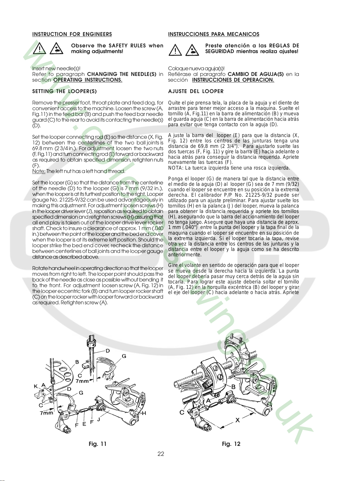
SETTING THE LOOPER(S)
Remove the presser foot, throat plate and feed dog, for
convenient access to the machine. Loosen the screw (A,
Fig.11) in the feed bar (B) and push the feed bar needle
guard (C) to the rear to avoid its contacting the needle(s)
(D).
Set the looper connecting rod (E) so the distance (X, Fig.
12) between the centerlines of the two ball joints is
69.8 mm (2 3/4 in.). For adjustment loosen the two nuts
(F, Fig.11) and turn connecting rod (E) forward or backward
as required to obtain specified dimension, retighten nuts
(F).
Note: The left nut has a left hand thread.
Set the looper (G) so that the distance from the centerline
of the needle (D) to the looper (G) is 7 mm (9/32 in.),
when the looper is at its furthest position to the right. Looper
gauge No. 21225-9/32 can be used advantageously in
making this adjustment. For adjustment loosen screws (H)
in the looper driver lever (J), reposition as required to obtain
specified dimension and retighten screws (H) assuring that
all end play is taken out of the looper drive lever rocker
shaft. Check to insure a clearance of approx. 1 mm (.040
in.) between the point of the looper and the bed end cover
when the looper is at its extreme left position. Should the
looper strike the bed end cover, recheck the distance
between centerlines of ball joints and the looper gauge
distance as described above.
Rotate handwheel in operating direction so that the looper
moves from right to left. The looper point should pass the
back of the needle as close as possible without bending it
to the front. For adjustment loosen screw (A, Fig. 12) in
the looper eccentric fork (B) and turn looper rocker shaft
(C) on the looper rocker with looper forward or backward
as required. Retighten screw (A).
OPERATING INSTRUCTIONS.
Coloque nueva aguja(s)!
Refiérase al paragrafo CAMBIO DE AGUJA(S) en la
sección
AJUSTE DEL LOOPER
Quite el pie prensa tela, la placa de la aguja y el diente de
arrastre para tener mejor acceso a la maquina. Suelte el
tornillo (A, Fig.11) en la barra de aliment ación (B) y mueva
el guarda aguja (C) en la barra de alimentación hacia atrás
para evitar que tenga contacto con la aguja (D).
A juste la barra del looper (E) para que la distancia (X,
Fig. 12) entre los centros de las junturas tenga una
distancia de 69,8 mm (2 3/4"). Para ajustarlo suelte las
dos tuercas (F, Fig. 11) y gire la barra (E) hacia adelante o
hacia atrás para conseguir la distancia requerida. Apriete
nuevamente las tuercas (F).
NOTA: La tuerca izquierda tiene una rosca izquierda.
Ponga el looper (G) de manera tal que la distancia entre
el medio de la aguja (D) al looper (G) sea de 7 mm (9/32)
cuando el looper se encuentre en su posición a la extrema
derecha. El calibrador P/P No. 21225-9/32 puede ser
utilizado para un ajuste preliminar. Para ajustar suelte los
tornillos (H) en la palanca (J) del looper, mueva la p alanca
para obtener la distancia requerida y apriete los tornillos
(H), asegurando que la barra del accionamiento del looper
no tenga juego. Asegure que haya una distancia de aprox.
1 mm (.040") entre la punta del looper y la tapa final de la
maquina cuando el looper se encuentre en su posición de
la extrema izquierda. Si el looper tocaría la tapa, revise
otra vez la distancia entre los centros de las junturas y la
distancia entre el looper y la aguja como se ha descrito
anteriormente.
Gire el volante en sentido de operación para que el looper
se mueva desde la derecha hacia la izquierda. La punta
del looper debería pasar muy cerca detrás de la aguja sin
tocarla. Para lograr este ajuste debería soltar el tornillo
(A, Fig. 12) en la horquilla excéntrica (B) del looper y girar
el eje del looper (C) hacia adelante o hacia atrás. Apriete
Preste atención a las REGLAS DE
SEGURIDAD mientras realiza ajustes!
INSTRUCCIONES DE OPERACION.
Fig. 11 Fig. 12
22
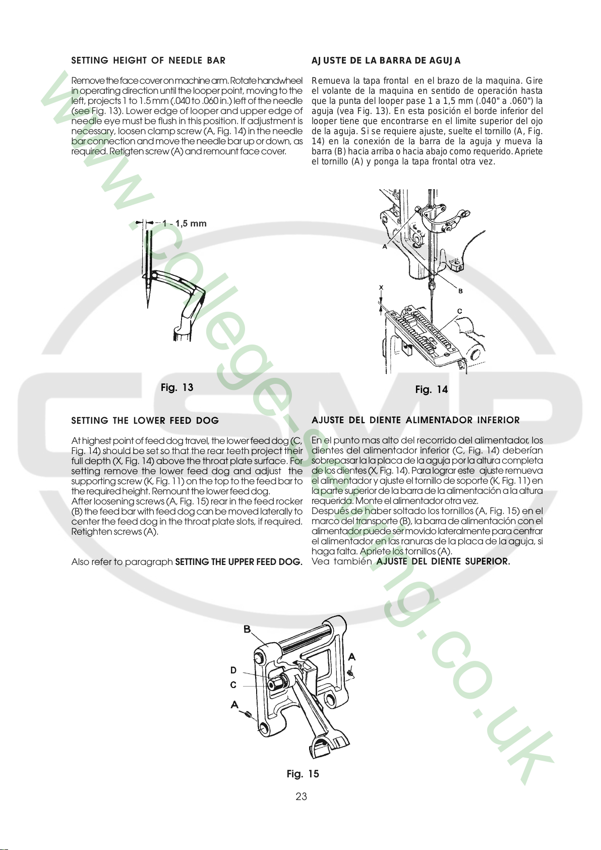
SETTING HEIGHT OF NEEDLE BAR
AJUSTE DE LA BARRA DE AGUJA
Remove the face cover on machine arm. Rotate handwheel
in operating direction until the looper point, moving to the
left, projects 1 to 1.5 mm (.040 to .060 in.) left of the needle
(see Fig. 13). Lower edge of looper and upper edge of
needle eye must be flush in this position. If adjustment is
necessary, loosen clamp screw (A, Fig. 14) in the needle
bar connection and move the needle bar up or down, as
required. Retigten screw (A) and remount face cover.
Remueva la tapa frontal en el brazo de la maquina. Gire
el volante de la maquina en sentido de operación hasta
que la punta del looper pase 1 a 1,5 mm (.040" a .060") la
aguja (vea Fig. 13). En esta posición el borde inferior del
looper tiene que encontrarse en el limite superior del ojo
de la aguja. Si se requiere ajuste, suelte el tornillo (A, Fig.
14) en la conexión de la barra de la aguja y mueva la
barra (B) hacia arriba o hacia abajo como requerido. Apriete
el tornillo (A) y ponga la tapa frontal otra vez.
Fig. 13
SETTING THE LOWER FEED DOG
At highest point of feed dog travel, the lower feed dog (C,
Fig. 14) should be set so that the rear teeth project their
full depth (X, Fig. 14) above the throat plate surface. For
setting remove the lower feed dog and adjust the
supporting screw (K, Fig. 11) on the top to the feed bar to
the required height. Remount the lower feed dog.
After loosening screws (A, Fig. 15) rear in the feed rocker
(B) the feed bar with feed dog can be moved laterally to
center the feed dog in the throat plate slots, if required.
Retighten screws (A).
Also refer to paragraph SETTING THE UPPER FEED DOG.
Fig. 14
AJUSTE DEL DIENTE ALIMENTADOR INFERIOR
En el punto mas alto del recorrido del alimentador, los
dientes del alimentador inferior (C, Fig. 14) deberían
sobrepasar la la placa de la aguja por la altura completa
de los dientes (X, Fig. 14). Para lograr este ajuste remueva
el alimentador y ajuste el tornillo de soporte (K, Fig. 11) en
la parte superior de la barra de la alimentación a la altura
requerida. Monte el alimentador otra vez.
Después de haber soltado los tornillos (A, Fig. 15) en el
marco del transporte (B), la barra de alimentación con el
alimentador puede ser movido lateralmente para centrar
el alimentador en las ranuras de la placa de la aguja, si
haga falta. Apriete los tornillos (A).
Vea también AJUSTE DEL DIENTE SUPERIOR.
Fig. 15
23
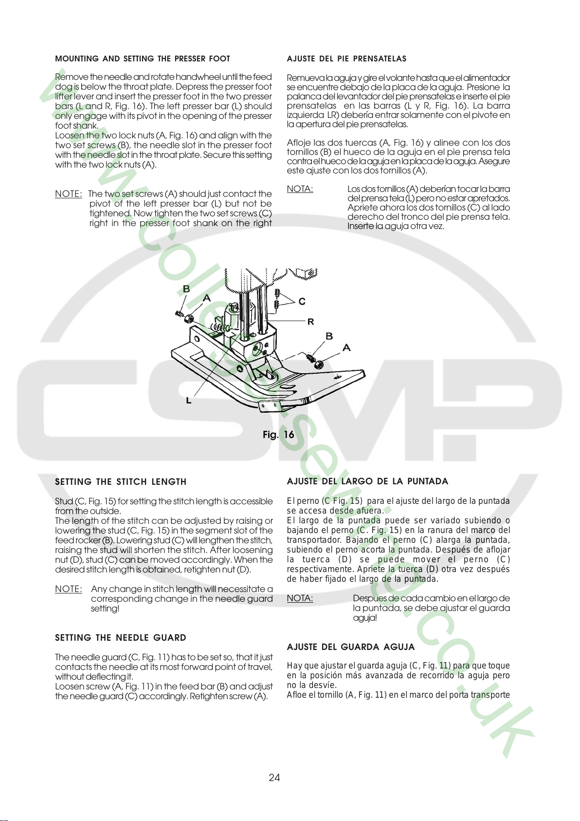
MOUNTING AND SETTING THE PRESSER FOOT
AJUSTE DEL PIE PRENSATELAS
Remove the needle and rotate handwheel until the feed
dog is below the throat plate. Depress the presser foot
lifter lever and insert the presser foot in the two presser
bars (L and R, Fig. 16). The left presser bar (L) should
only engage with its pivot in the opening of the presser
foot shank.
Loosen the two lock nuts (A, Fig. 16) and align with the
two set screws (B), the needle slot in the presser foot
with the needle slot in the throat plate. Secure this setting
with the two lock nuts (A).
NOTE: The two set screws (A) should just contact the
pivot of the left presser bar (L) but not be
tightened. Now tighten the two set screws (C)
right in the presser foot shank on the right
Remueva la aguja y gire el volante hasta que el alimentador
se encuentre debajo de la placa de la aguja. Presione la
palanca del levantador del pie prensatelas e inserte el pie
prensatelas en las barras (L y R, Fig. 16). La barra
izquierda LR) debería entrar solamente con el pivote en
la apertura del pie prensatelas.
Afloje las dos tuercas (A, Fig. 16) y alinee con los dos
tornillos (B) el hueco de la aguja en el pie prensa tela
contra el hueco de la aguja en la placa de la aguja. Asegure
este ajuste con los dos tornillos (A).
NOTA: Los dos tornillos (A) deberían tocar la barra
del prensa tela (L) pero no estar apretados.
Apriete ahora los dos tornillos (C) al lado
derecho del tronco del pie prensa tela.
Inserte la aguja otra vez.
Fig. 16
SETTING THE STITCH LENGTH
Stud (C, Fig. 15) for setting the stitch length is accessible
from the outside.
The length of the stitch can be adjusted by raising or
lowering the stud (C, Fig. 15) in the segment slot of the
feed rocker (B). Lowering stud (C) will lengthen the stitch,
raising the stud will shorten the stitch. After loosening
nut (D), stud (C) can be moved accordingly. When the
desired stitch length is obtained, retighten nut (D).
NOTE: Any change in stitch length will necessitate a
corresponding change in the needle guard
setting!
SETTING THE NEEDLE GUARD
The needle guard (C, Fig. 11) has to be set so, that it just
contacts the needle at its most forward point of travel,
without deflecting it.
Loosen screw (A, Fig. 11) in the feed bar (B) and adjust
the needle guard (C) accordingly. Retighten screw (A).
AJUSTE DEL LARGO DE LA PUNTADA
El perno (C Fig. 15) para el ajuste del largo de la puntada
se accesa desde afuera.
El largo de la puntada puede ser variado subiendo o
bajando el perno (C. Fig. 15) en la ranura del marco del
transportador. Bajando el perno (C) alarga la puntada,
subiendo el perno acorta la puntada. Después de aflojar
la tuerca (D) se puede mover el perno (C)
respectivamente. Apriete la tuerca (D) otra vez después
de haber fijado el largo de la puntada.
NOTA: Despues de cada cambio en el largo de
la puntada, se debe ajustar el guarda
aguja!
AJUSTE DEL GUARDA AGUJA
Hay que ajustar el guarda aguja (C, Fig. 1 1) para que toque
en la posición más avanzada de recorrido la aguja pero
no la desvíe.
Afloe el tornillo (A, Fig. 11) en el marco del port a transporte
24
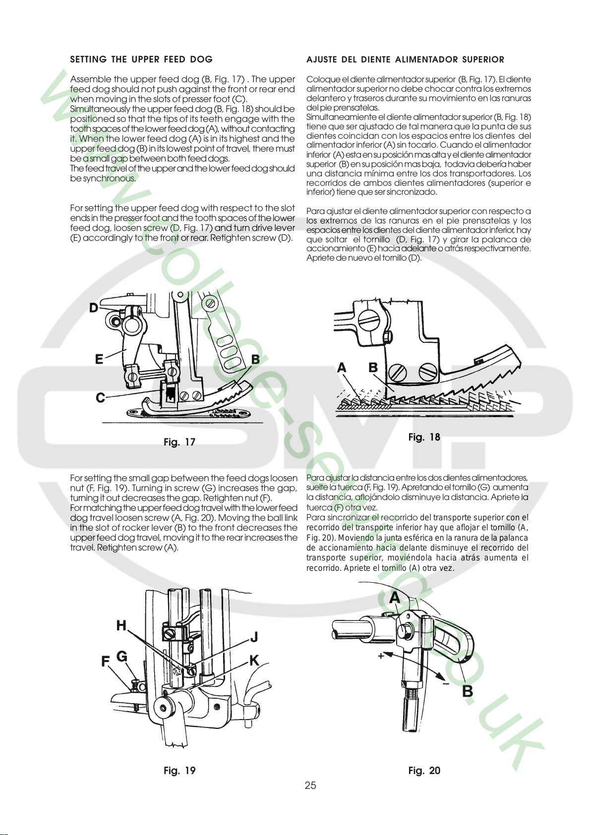
SETTING THE UPPER FEED DOG
AJUSTE DEL DIENTE ALIMENTADOR SUPERIOR
Assemble the upper feed dog (B, Fig. 17) . The upper
feed dog should not push against the front or rear end
when moving in the slots of presser foot (C).
Simultaneously the upper feed dog (B, Fig. 18) should be
positioned so that the tips of its teeth engage with the
tooth spaces of the lower feed dog (A), without contacting
it. When the lower feed dog (A) is in its highest and the
upper feed dog (B) in its lowest point of travel, there must
be a small gap between both feed dogs.
The feed travel of the upper and the lower feed dog should
be synchronous.
For setting the upper feed dog with respect to the slot
ends in the presser foot and the tooth spaces of the lower
feed dog, loosen screw (D, Fig. 17) and turn drive lever
(E) accordingly to the front or rear. Retighten screw (D).
Coloque el diente alimentador superior (B, Fig. 17). El diente
alimentador superior no debe chocar contra los extremos
delantero y traseros durante su movimiento en las ranuras
del pie prensatelas.
Simultaneamiente el diente alimentador superior (B, Fig. 18)
tiene que ser ajustado de tal manera que la punta de sus
dientes coincidan con los espacios entre los dientes del
alimentador inferior (A) sin tocarlo. Cuando el alimentador
inferior (A) esta en su posición mas alta y el diente alimentador
superior (B) en su posición mas baja, todavia debería haber
una distancia mínima entre los dos transportadores. Los
recorridos de ambos dientes alimentadores (superior e
inferior) tiene que ser sincronizado.
Para ajustar el diente alimentador superior con respecto a
los extremos de las ranuras en el pie prensatelas y los
espacios entre los dientes del diente alimentador inferior, hay
que soltar el tornillo (D, Fig. 17) y girar la palanca de
accionamiento (E) hacia adelante o atrás respectivamente.
Apriete de nuevo el tornillo (D).
Fig. 17
For setting the small gap between the feed dogs loosen
nut (F, Fig. 19). Turning in screw (G) increases the gap,
turning it out decreases the gap. Retighten nut (F).
For matching the upper feed dog travel with the lower feed
dog travel loosen screw (A, Fig. 20). Moving the ball link
in the slot of rocker lever (B) to the front decreases the
upper feed dog travel, moving it to the rear increases the
travel. Retighten screw (A).
Fig. 18
Para ajustar la distancia entre los dos dientes alimentadores,
suelte la tuerca (F, Fig. 19). Apretando el tor nillo (G) aumenta
la distancia, aflojándolo disminuye la distancia. Apriete la
tuerca (F) otra vez.
Para sincronizar el recorrido del transporte superior con el
recorrido del transporte inferior hay que aflojar el tornillo (A,
Fig. 20). Moviendo la junta esférica en la ranura de la palanca
de accionamiento hacia delante disminuye el recorrido del
transporte superior, moviéndola hacia atrás aumenta el
recorrido. Apriete el tornillo (A) otra vez.
Fig. 19 Fig. 20
25
HINT: In general the travels of lower and upper feed dog
are set equally. Depending on the fabric to be sewn
however, it may be necessary to set a slightly longer
upper feed dog travel in order to get a proper end
matching of the fabric plies.
Also refer to paragraph SETTING THE STITCH
LENGTH.
NOTA: Normalmente se ajustan recorridos iguales
para el transporte inferior y el superior.
Dependiendo del material que se va a coser
podría ser necesario alargar el recorrido del
transporte superior para compensar un
desplazamiento de las telas.
Vea t ambien al capítulo AJUSTE DEL LARGO
DE LA PUNTADA.
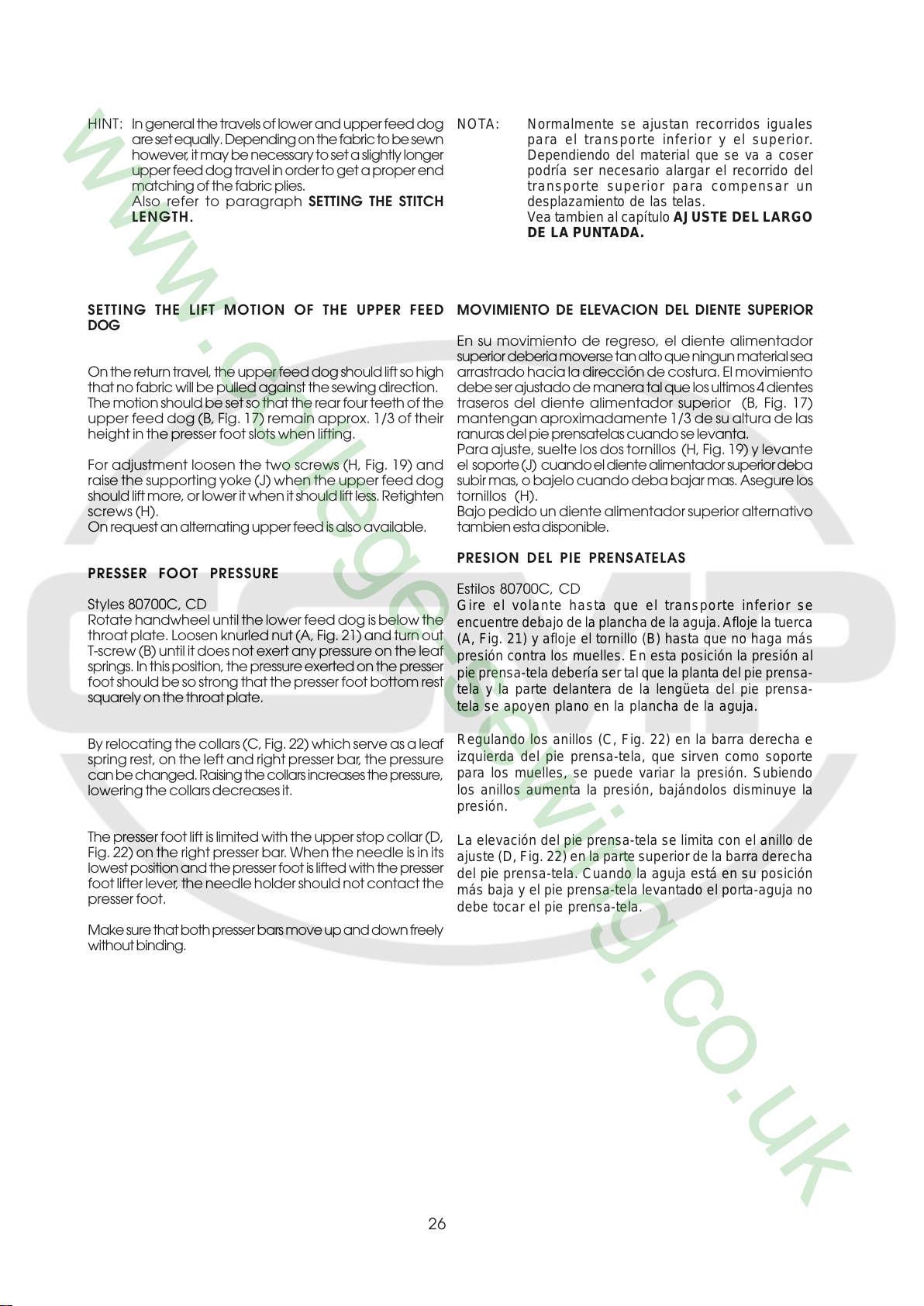
SETTING THE LIFT MOTION OF THE UPPER FEED
DOG
On the return travel, the upper feed dog should lift so high
that no fabric will be pulled against the sewing direction.
The motion should be set so that the rear four teeth of the
upper feed dog (B, Fig. 17) remain approx. 1/3 of their
height in the presser foot slots when lifting.
For adjustment loosen the two screws (H, Fig. 19) and
raise the supporting yoke (J) when the upper feed dog
should lift more, or lower it when it should lift less. Retighten
screws (H).
On request an alternating upper feed is also available.
PRESSER FOOT PRESSURE
Styles 80700C, CD
Rotate handwheel until the lower feed dog is below the
throat plate. Loosen knurled nut (A, Fig. 21) and turn out
T-screw (B) until it does not exert any pressure on the leaf
springs. In this position, the pressure exerted on the presser
foot should be so strong that the presser foot bottom rest
squarely on the throat plate.
By relocating the collars (C, Fig. 22) which serve as a leaf
spring rest, on the left and right presser bar, the pressure
can be changed. Raising the collars increases the pressure,
lowering the collars decreases it.
MOVIMIENTO DE ELEVACION DEL DIENTE SUPERIOR
En su movimiento de regreso, el diente alimentador
superior deberia moverse tan alto que ningun material sea
arrastrado hacia la dirección de costura. El movimiento
debe ser ajustado de manera tal que los ultimos 4 dientes
traseros del diente alimentador superior (B, Fig. 17)
mantengan aproximadamente 1/3 de su altura de las
ranuras del pie prensatelas cuando se levanta.
Para ajuste, suelte los dos tornillos (H, Fig. 19) y levante
el soporte (J) cuando el diente alimentador superior deba
subir mas, o bajelo cuando deba bajar mas. Asegure los
tornillos (H).
Bajo pedido un diente alimentador superior alternativo
tambien esta disponible.
PRESION DEL PIE PRENSATELAS
Estilos 80700C, CD
Gire el volante hasta que el transporte inferior se
encuentre debajo de la plancha de la aguja. Afloje la tuerca
(A, Fig. 21) y afloje el tornillo (B) hasta que no haga más
presión contra los muelles. En esta posición la presión al
pie prensa-tela debería ser tal que la planta del pie prensa-
tela y la parte delantera de la lengüeta del pie prensa-
tela se apoyen plano en la plancha de la aguja.
Regulando los anillos (C, Fig. 22) en la barra derecha e
izquierda del pie prensa-tela, que sirven como soporte
para los muelles, se puede variar la presión. Subiendo
los anillos aumenta la presión, bajándolos disminuye la
presión.
The presser foot lift is limited with the upper stop collar (D,
Fig. 22) on the right presser bar. When the needle is in its
lowest position and the presser foot is lifted with the presser
foot lifter lever, the needle holder should not contact the
presser foot.
Make sure that both presser bars move up and down freely
without binding.
26
La elevación del pie prensa-tela se limita con el anillo de
ajuste (D, Fig. 22) en la parte superior de la barra derecha
del pie prensa-tela. Cuando la aguja está en su posición
más baja y el pie prensa-tela levantado el porta-aguja no
debe tocar el pie prensa-tela.

Now turn in T-screw (B, Fig. 21) until the necessary
presser foot pressure for proper feeding is exerted
(determine by sewing tests). Secure this setting with the
knurled nut (A) which simultaneously fastens the upper
arm cover. Remount the face cover and the finger guard.
Ahora apriete el tornillo (B, Fig. 21) hasta que haya
suficiente presión al pie prensatela para el transporte
de la tela (compruebe con ensayos de costura). Asegure
esta posición con la tuerca (A) , con la cual se fija
simultáneamente la tapa superior en el brazo de la
máquina. Coloque otra vez la tapa lateral en el brazo y
el protector de los dedos.
Fig. 21
NEEDLE THREAD TAKE-UP
Basically the needle thread take-up roller (B, Figs. 9 and
10) located left on the upper bed casting under the face
cover, is set in the middle of its shaft.
In case more needle thread should be pulled off for a
bigger needle thread loop (depending on thread and fa-
bric), raise the needle thread take-up roller accordingly.
Fasten the needle thread guide (C, Figs. 9 and 10),
located on the top of the upper bed casting, approx. in
the middle of its shank.
THREAD TENSION
Regulate the tension on the threads so that uniform
stitches are produced.
In general the tension applied to the needle thread is
slightly higher than the tension applied to the looper
thread.
Turning the tension nuts clockwise increases the
tension, turning counterclockwise decreases the
tension.
Fig. 22
ALIMENTACION DEL HILO DE LA AGUJA
Generalmente el rodillo del alimentador del hilo de la
aguja (B, Figs. 9 y 10), que está situado en la parte
delantera izquierda del brazo debajo de la tapa frontal,
debería estar fijado en la mitad de su mango.
En el caso que se necesite más hilo para crear un lazo
de hilo más grande (dependiendo del hilo y tela) tiene
que subir el rodillo adecuadamente.
Fije el guía hilo (C, Fig. 2 y 2 A), que está situada en la
parte delantera superior del brazo, aproximadamente en
la mitad de su mango.
TENSION DE LOS HILOS
Regule la tensión de los hilos de tal manera que se logre
una formación uniforme de la costura.
Normalmente el hilo de la aguja tiene más tensión que el
hilo del looper.
Girar las tuercas del tensor en sentido de reloj aumenta
la tensión, girar en sentido contra el reloj disminuye la
27

LOOPER THREAD TAKE-UP
ALIMENTACION DEL HILO DEL LOOPER
On the two thread double locked stitch machines, the
height of the looper thread take-up (A, Fig. 23) is set so
that the cast-off hook (C) forces the looper thread over
the corner (B) of the looper thread take-up (A) at the
time the point of the descending needle is flush with the
lower edge of looper or projects up to 1 mm (0.40 in.)
below the lower edge of looper.
Draw the looper thread into the machine, rotate
handwheel in operating direction and note the position
of the needle point to lower edge of looper at the time the
cast-off (C) forces the looper thread over the corner (B).
For setting the looper thread take-up loosen screw (D,
Fig. 23). When the needle point is positioned above the
lower edge of looper, the looper thread take-up (A) has
to be raised accordingly. When the needle point is
positioned more than 1 mm (.040 in.) below the lower
edge of looper the looper thread take-up (A) has to be
lowered accordingly. Retighten screw (D).
En las máquinas de costura de doble cadeneta de dos
hilos se ajusta la altura del alimentador del hilo del looper
(A, Fig. 23) de tal manera que el gancho del alimentador
del hilo del looper (C) suelte el hilo sobre el canto (B) del
alimentador (A) en el momento cuando la punta de la aguja
coincide con el borde inferior del looper.
Enhebre el hilo del looper, gire el volante en sentido de
operación y memorice la posición de la punta de la aguja
referente al looper en el momento cuando el gancho del
alimentador (C) suelte el hilo sobre el canto (B).
Para ajustar el alimentador del hilo del looper suelte el
tornillo (D, Fig. 23). Si la punta de la aguja se encuentra
por encima del borde inferior del looper, hay que ajustar el
alimentador (A) hacia arriba. Si la punta de la aguja se
encuentra más que 1 mm por debajo del borde inferior
del looper, hay bajar el alimentador adecuadamente.
Apriete el tornillo (D) otra vez.
SETTING THE THREAD CHAIN CUTTING KNIVES
Styles 80700C, C1, CD, CD1
Set the stationary knife (A, Fig. 24) so that its tip is flush
with the supporting surface for the throat plate on the
bed casting.
Fasten the movable knife (B) in the knife lever so that its
tip moves freely .012 to .020 in. (0.3 - 0.5 mm) below
the underside of the throat plate and its cutting edge
overlaps the cutting edge of the stationary knife by .040
in. (0.5 mm).
Fig. 23
AJUSTE DEL CORTADOR DE CADENETA DE LOS
HILOS
Estilos 80700C, C1, CD, CD1
Ajuste la cuchilla fija (A, Fig. 24) de tal manera que su
punta coincida con la superficie de la cama, en la cual
reposa la placa de la aguja.
Coloque la cuchilla móvil (B) de tal manera en la palanca
de la cuchilla, para que su punta pase libremente
aproximadamente de 0,3 hasta 0,5 mm por debajo del la
Fig. 24
28

SETTING THE TIME RELAYS IN THE SWITCH BOX
OF HOT THREAD CHAIN CUTTER
Styles 80700C1H, CD1H
AJUSTE DE LOS RELES DE TIEMPO IN LA CAJA DE
CONTROL DEL CORTADOR CALIENTE DE CADENETA
Estilos 80700C1H, CD1H
The switch box includes two time relays marked K2T
and K4T.
Set the heat up periode for the knife for hot cutter on
relay K2T to approximately 3 seconds.
Choose the time delay between two cutting operations
on relay K4T. Recommended delay should be set to
approximately 10 seconds.
La caja de control incluye dos relés de tiempo marcados
K2T y K4T.
Ajuste a 3 segundos aproximadamente el período de
tiempo para la cuchilla de corte caliente.
Seleccione el tiempo de espera entre las dos operaciones
de corte en el relé K4T. Se recomiemda ajustar a 10
segundos aproximadamente el tiempo de espera.
TORQUE REQUIREMENTS
Torque specifications given in this catalog are measured
in Nm (Newtonmeter and inch-pound (in.lbs.). All straps
and eccentrics must be tightened to 2.2 - 2.4 Nm (19 - 21
in.lbs), unless otherwise noted. All nuts, bots, screws etc.
without torque specifications must be secured as tightly
as possible, unless otherwise noted. Special torque
specifications of connecting rods, links, screws etc. are
shown on part illustrations.
REQUERIMIENTOS DE ESFUERZOS DE TORSION
(TORQUE)
Las especificaciones de los torques se indican en este
catálogo en Nm (Newtonmetros) y pulgada-libra (in.lbs).
Todos los cojinetes de conexión y excéntricas hay que
apretar con 2,2 – 2,4 Nm (19 – 21 in.lbs) a no ser que se
indique de otra manera. T odas las tuercas, pernos, tornillos
etc. sin indicaciones de torques deberían ser apretadas lo
máximo posible, si no se indica de otra manera.
Especificaciones especiales de los torques para barras
de conexión, junturas, tornillos etc. se encuentran en las
ilustraciones de las partes y piezas.
29

ORDERING WEAR AND SPARE PARTS
PEDIDO DE PIEZAS DE REPUESTOS
The following section of this manual simplifies ordering
wear and spare parts. Exploded views of various sections
of the mechanism are shown so that the parts may be
seen in their actual position in the sewing machine. On
the page opposite the illustration will be found a listing of
the parts with their part numbers, descriptions and the
number of pieces required in the particular view being
shown.
Numbers in the first column are reference numbers only,
and merely indicate the position of that part in the
illustration. Reference numbers should never be used in
ordering parts. Always use the part number listed in the
second column.
Component parts of sub-assemblies which can be
furnished for repairs are indicated by indenting their
descriptions under the description of the main sub-
assembly. As an example refer to the following text:
25 29479 Looper Rocker Assembly for 80700C Palanca completa del looper para 80700 C 1
26 15745B Cone Stud Perno cónico 1
27 80613A Looper Rocker Palanca del looper 1
28 15465F Cone Anillo cónico 1
29 88 Screw Tornillo 2
Este catálogo fue diseñado para facilitar los pedidos de
los repuestos. Los dibujos de grupos específicos del
mecanismo demuestran la posición de las piezas en la
máquina de coser. En la página en frente de la página de
la ilustración se encuentra un listado de las piezas con su
número de repuesto, descripción y la cantidad requerida
para la sección indicada.
Los números de la primera columna son números de
referencia e indican donde se encuentra la piezas en la
ilustración. Los números de referencia no se deben utilizar
en sus pedidos de repuestos. Utilice siempre el número
de repuesto de la segunda columna.
Componentes de piezas compuestas que se pueden
suministrar como repuestos se encuentran diferenciados
en tal forma que las descripciones están desplazadas hacia
la derecha referente a la descripción de la pieza compuesta.
Vea el ejemplo del texto siguiente:
At the back of the catalog will be found a numerical index
of all parts shown in this catalog. This will facilitate locating
the illustration and description when only the part number
is known.
IMPORTAN! ON ALL ORDERS, PLEASE INCLUDE
PART NUMBER, PART NAME AND STYLE
Al final de este catálogo se encuentra un listado de los
números de partes de todos los repuestos que están
descritos en el mismo. Esto facilita encontrar la ilustración
y descripción de la pieza en el caso que solamente se
conozca el número del repuesto.
NOTA! FAVOR INDICAR EN TODOS LOS PEDIDOS
EL NUMERO, LA DESCRIPCION DEL
REPUESTO Y EL MODELO DE LA MAQUINA
30

VIEWS AND DESCRIPTION
OF PARTS
VISTAS Y DESCRIPCION
LAS PARTES Y PIEZAS
31

32

BUSHINGS AND OILING PARTS
BOCINAS Y PARTES DE LUBRICACION
Ref. No.
Ref. No.
1*
2*
3
4
5
6
7
8
9
10
11*
12*
13
14*
15*
16
17
18
19
20
21
22
23
24
25*
26*
27*
28*
29
30
31
32
33
34
Part No.
Parte No.
80862
81373A
666-79
80293A
22894K
22894J
80846
89
88
80644
80640EA
80694DA
95861
80692EA
80694DC
80885
80885B
22891
80885
999-106D
80885C
22596D
HA95
HA81
80639FA
80639EA
80692DA
80640EA
22539
15430L
WO3
80689C
80689D
G41046G
Description
Presser Bar Bushing
Needle Bar Bushing
Sight Feed Oiler
Oil Distributor
Spot Screw, headless
Set Screw
Bushing for needle lever shaft
Spot Screw, headless
Set Screw
Plug Screw
Bushing, left for upper feed
drive shaft
Bushing, right for upper feed
drive shaft
Screw
Bushing for feed rocker shaft
Bushing for crank shaft
Ball Bearing Assy crank shaft
Hub
Screw
Ball Bearing
Deep Groove Ball Bearing
Retaining Ring
Screw
Set Screw
Spot Screw, headless
Bushing, left for looper shaft
Bushing, right for looper shaft
Bushing for knife lever shaft
Bushing for looper drive
rocker
Plug Screw
Felt
Cotton Swab (as required)
Spring Valve Oiler
Spring Valve Oiler
Descripción
Bocina de la barra elevadora
Bocina de la barra de aguja
Visor de la aceitera
Distribuidor del aceite
Tornillo de punto fijo, sin cabeza
Tornillo de sujeción
Bocina palanca elevadora barra
Tornillo de punto fijo, sin cabeza
Tornillo de sujeción
Tornillo tapa
Bocina, izquierda
transporte superior
Bocina, derecha
transporte superior
Tornillo
Bocina del Eje oscilante del alimentador
Bocina del cigueñal
Conj. cojinete de bolas del cigueñal
Manguito
Tornillo
Cojinete de bolas
Rodamiento
Empaquetadura de retención
Tornillo
Tornillo de sujeción
Tornillo de punto fijo, sin cabeza
Bocina, izquierda eje looper
Bocina, derecha eje looper
Bocina eje cuchilla
Bocina eje movimiento looper
Tornillo tapa
Fieltro
Mota de algodón (cuando requerida)
Resorte valvula aceite
Resorte valvula aceite
Resorte valvula aceite
4
2
1
1
1
1
2
1
1
2
1
1
3
2
2
1
1
2
1
1
1
3
1
1
1
1
2
2
2
2
1
8
1
Amt. Req.
Cant.Req.
NOTE: Bushings marked with an asterisk are cemented in the bed
basting. Instead of single bushings we recommend to order
the following repair sets which include the required amount
of bushings with engineering adhesive and instructions.
Presser Bar Bushings (Ref. No. 1)
29916REE
29916REF
29916REM
Needle Bar Bushings (Ref. No. 2)
Bushings for upper feed drive shaft
(Ref. Nos. 11 and 12)
Bushings for feed rocker shaft
29916REL
(Ref. No. 17)
Bushings for looper driver rocker shaft
29916REQ
(Ref. No. 18)
Bushings for crankshaft (Ref. No. 15)
29916RES
29916REK
Bushings for looper shaft
(Ref. Nos. 25 + 26)
Bushings for knife lever shaft
29916REN
(Ref. No. 27)
IMPORTANT! When cementing, align the oil holes in the
bushings with the oil holes in the bed casting!
NOTA: Bocinas marcadas con asterico estan cementadas
en la cama de la máquina. En lugar de bocinas
ordinarias, recomendamos ordenar los siguientes
Juegos de reparación, que incluyen las cantidades
necesarias de bocinas, pega no permanente e
instrucciones.
Bocinas para barra elevadora (Ref. No. 1) 1
Bocinas barra de aguja (Ref. No. 2) 1
Bocinas para transporte superior 1
(Ref. Nos. 11 y 12)
Bocinas para Eje oscilante del alimentador 1
(Ref. No. 17)
Bocinas para eje de movimiento del looper 1
(Ref. No. 18)
Bocinas del cigueñal (Ref. No. 15) 1
Bocinas del eje del looper 1
(Ref. Nos. 25 + 26)
Bocinas para eje de la palanca de las cuchillas 1
(Ref. No. 27)
NOTA! Cuando use la pega no permanente,
alinie los huecos del aceite con los
huecos en la cama de la carcasa!
33

34

Ref. No.
Ref. No.
Part No.
Parte No.
CLOTH PLATES AND MISCELLANEOUS COVERS
Description
TAPA DE LA CAMA Y OTRAS TAPAS
Descripción
Amt. Req.
Cant.Req.
1
2
3
4
4A
4B
4C
5
6
7
8
9
10
11
12
13
13A
14
15
16
16A
16B
16C
17
18
19
20
21
22
80888
64Y
35733B
80701CA
A10409A
80701
A10409E
22574
A10405
25S
81387
22528
A9453A
AS126
80683
A10411
80782
92121
J1614
80701CB
A10409B
80701A
A10409D
80440
81239
80438
89
8564
999-216E
Arm Cover
T-Screw
Knurled Nut
Cloth Plate 80700C
Cloth Plate
80700CD
Cloth Plate for
80700C2, CD2
Cloth Plate for
0700C1, C1H, CD1,
CD1H
Countersunk Screw
Cover
Screw
Face Cover
Screw
Finger Guard for
80700C
Washer
End Cover for
80700C
End Cover for
80700CD
End Cover for
80700C1, C1H, C2,
CD1, CD1H, CD2
Shoulder Screw
Spring Washer
Hinge Cover
Assembly for
80700C
(2 threaded holes)
Hinge Cover Assy for
80700CD
(4 threaded holes)
Hinge Cover Assembly
for 80700C2, CD2
(4 threaded holes)
Hinge Cover Assy for
80700C1, C1H, CD1,
CD1H (4 threaded
holes)
Locking Bolt Knob
Locking Bolt
Spring
Cubierta del brazo
Tornillo T
Tuerca estriada
Tapa para 80700C
Tapa para 80700CD
Tapa para 80700C2,
CD2
Placa para 80700C1,
C1H, CD1, CD1H
Tornillo remache
Cubierta
Tornillo
Cubierta frontal
Tornillo
Guardadedos para
80700C
Arandela
Cubierta final para
80700C
Cubierta final para
80700CD
Cubierta final para
80700C1, C1H, C2
CD1, CD1H, CD2
Tornillo de encuentro
Arandela resorte
Cubierta articulada
para 80700C
(2 huecos
incorporados)
Cubierta articulada
para 80700CD
(4 huecos
incorporados)
Cubierta articulada
ara 80700C2, CD2
p
(4 huecos
incorporados)
Cubierta articulada
para 80700C1, C1H,
CD1, CD1H (4 huecos
incorporados)
Perno de seguridad
Perno de seguridad
Resorte
1
1
1
1
1
1
1
3
1
2
1
2
1
1
1
1
1
1
1
1
1
1
1
1
1
1
2
1
1
35

36

THREAD TENSION, THREAD GUIDES AND NEEDLE BAR GUARD FOR 80700C, C1, C1H, C2
TENSION DEL HILO, GUIA HILOS Y PROTECTOR DE LA BARRA DE AGUJA PARA 80700C, C1, C1H, C2
Ref. No.
Ref. No.
1
2
3
4
5
6
7
8
9
10
11
12
13
14
15
16
17
18
19
20
21
22
23
24
25
26
27
28
29
Part No.
Parte No.
AS135
HA103B
28C
22894AD
80667
81256A
22560B
HS106
HA1349
80676A
HA1349
HS110A
110-2
107
108
80858BX1
80858BX2
28C
22894AD
80665D
88
80668
HS53B
22560
HA1286B
12964C
81086G
22894AD
80673CB
Description
Holder
Eyelet
Screw
Set Screw
Pin for tension discs
Thread Sleeve
Set Screw
Tension Post
Tension Post Ferrule
Tension Disc
Tension Sleeve
Spring for needle thread tension
Spring for looper thread tension
Tension Spring Ferrule
Tension Nut
Holder
Ferrule
Set Screw
Set Screw
Needle Thread Take-up Roller
Set Screw
Take-up Roller
Roller Stud Assembly
Set Screw
Spring
Spring Ball
Roller Stud
Set Screw
Needle Bar Guard
Descripción
Sujetador
Pasahilo
Tornillo
Tornillo de sujeción
Pasador de los discos de tensión
Guía hilo
Tornillo de sujeción
Poste de tensión
Distanciador del poste de tensión
Disco de tensión
Poste de tensión
Resorte tensión del hilo de la aguja
Resorte tensión del hilo del looper
Distanciador del resorte de tensión
Tuerca de la tensión
Sujetador
Distanciador
Tornillo de sujeción
Tornillo de sujeción
Conjunto guía hilo
Tornillo de sujeción
Rodillo guía hilo
Conjunto del rodillo perno
Tornillo
Resorte
Resorte de bola
Rodillo perno
Tornillo de sujeción
Guarda de la barra de aguja
Amt. Req.
Cant.Req.
1
1
1
1
2
2
2
2
2
4
2
1
1
2
2
1
1
1
1
1
1
1
1
1
1
1
1
1
1
37

38

THREAD TENSIONS, THREAD GUIDES AND NEEDLE BAR GUARD FOR 80700CD, CD1, CD1H, CD2
TENSION DEL HILO, GUIA HILOS Y PROTECTOR DE LA BARRA DE AGUJA PARA 80700CD, CD1, CD1H, CD2
Ref. No.
Ref. No.
1
2
3
4
5
6
7
8
9
10
11
12
13
14
15
16
17
18
19
20
21
22
23
24
25
26
27
28
29
30
31
32
33
34
35
36
37
38
39
40
41
Part No.
Parte No.
80250C
80250A
80668A
81086
22560
HA1286B
12964C
88
80250D
22743
81283
22894AD
81256A
81256B
AS135
28C
22560B
80655A
80667
HS106
81292A
HA1348
80676A
HA1349
HS110A
110-2
107
108
81254A
22894AD
81365A
81365
88
80668A
81386
22560
HA1286B
12964C
81386A
22894AD
80673CB
Description Descripción Amt. Req.
Cant.Req.
Needle Thread Roller Guide
Assembly Roller Support
Thread Guide Roller
Roller Stud Assembly
Set Screw
Spring
Spring Ball
Set Screw
Pin
Set Screw
Thread Guide Fork
Screw
Thread Sleeve
Thread Sleeve
Bracket
Set Screw
Set Screw
Pin for tension discs
Pin for tension discs
Tension Post
Tension Post
Tension Post Ferrule
Tension Disc
Tension Sleeve
Spring for needle thread tension
Spring for looper thread tension
Tension Spring Ferrule
Tension Nut
Looper Thread Eyelet
Set Screw
Needle Thread Take-up Roller
Assmbly Roller Support
Set Screw
Thread Guide Roller
Roller Stud Assembly
Set Screw
Spring
Spring Ball
Roller Stud
Set Screw
Needle Bar Guard
Conj. Guías Enhebrado hilo aguja
Rodillo sujetador
Rodillo guía hilo
Conj. Rodillo perno
Tornillo de sujeción
Resorte
Resorte de bola
Tornillo de sujeción
Pasador
Tornillo de sujeción
Tridente guía hilo
Tornillo
Pasa hilo
Pasa hilo
Soporte
Tornillo de sujeción
Tornillo de sujeción
Pasador discos de tensión
Pasador discos de tensión
Poste de tensión
Poste de tensión
Distanciador del poste de tensión
Disco de tensión
Manga de tensión
Resorte tensión hilo de la aguja
Resorte tensión hilo del looper
Resorte espaciador de la tensión
Tuerca de la tensión
Pasahilo del looper
Tornillo de sujeción
Conj. Rodillo tira hilo de la aguja
Soporte del rodillo
Tornillo de sujeción
Rodillo guia hilo
Conj. Rodillo Perno
Tornillo de sujeción
Resorte
Resorte de bola
Rodillo Perno
Tornillo de sujeción
Guarda de la barra de aguja
1
1
1
1
1
1
1
1
1
3
1
1
2
2
2
2
4
3
2
2
2
4
8
4
2
2
4
4
1
1
1
1
1
1
1
1
1
1
1
1
1
39

40

NEEDLE LEVER
PALANCA DE ACCIONAMIENTO DE LA BARRA DE AGUJA
Ref. No.
Ref. No.
1A
3A
10
11
12
12A
13
14
14A
15
16
16A
17
18
19*
20
21
21A
22
22A
23
24
24A
25
26
27
28
29
30
31
1
2
3
4
5
6
7
8
9
Part No.
Parte No.
80732A
80732
22894AD
51134Y
51134V
666-260
22870
258
22707
907
80768
79
80769
80770A
80770
22894Y
51134Y
51134V
666-260
80771A
80771
80772
80774
22882
80776
HA54B
HA54A
51134Y
51134V
666-260
80715A
80715
22894Y
22894C
22894J
22894H
96653
BP108
80643
Description
Guide Link for straight pin
Guide Link for taper pin
Set Screw
Link Pin, straight, Ø 6.53
Taper Pin
Felt Wick
Shank Screw
Nut
Screw
Nut
Supporting Yoke
Screw
Sliding Block
Lift Lever for straight pin
Lift Lever for taper pin
Set Screw
Link Pin, straight, Ø 6.53
Taper Pin
Felt Wick
Link for straight pin
Link for taper pin
Washer, leather
Guide
Hex. Head Cap Screw
Stud
Connecting Link for straight pin
Connecting Link for taper pin
Link Pin, straight, Ø 6.53 mm
Taper Pin
Felt Wick
Needle Lever for straight pin
Needle Lever for taper pin
Set Screw
Set Screw
Set Screw
Set Screw
Roll pin
Hex. Head Cap Screw
Needle Lever Shaft
Descripción
Guía conectora pasador cilíndrico
Guía conectora pasador cónico
Tornillo de sujeción
Pasador cilíndrico , Ø 6,53
Pasador cónico
Mecha de fieltro
Tornillo con tronco
Tuerca
Tornillo
Tuerca
Soporte
Tornillo
Bloque deslizador
Palanca elevadora pasador cilíndrico
Palanca elevadora pasador cónico
Tornillo de sujeción
Conector pasador cilíndrico, Ø 6,53
Pasador cónico
Mecha de fieltro
Conector para pasador cilíndrico
Conector para pasador cónico
Arandela, cuero
Guía
Tornillo tapa cabeza hexágonal
Perno
Conector para pasador cilíndrico
Conector para pasador cónico
Conector pasador cilíndrico, Ø 6,53
Pasador cónico
Mecha de fieltro
Elevador aguja pasador cilíndrico
Elevador aguja pasador cónico
Tornillo de sujeción
Tornillo de sujeción
Tornillo de sujeción
Tornillo de sujeción
Rodillo pasador
Tornillo tapa cabeza hexágonal
Eje del levantador aguja
Amt. Req.
Cant.Req.
1
1
4
1
1
1
1
1
1
1
1
2
1
1
1
2
1
1
2
1
1
1
1
2
1
1
1
1
1
1
1
1
1
1
1
1
1
1
* Used on alternating upper feed only * Solo para diente alimentador superior alternativo.
41

42


44

HORQUILLA EXCENTRICA ESQUIVA DEL LOOPER, LOOPER, PALANCAS LOOPER Y ACCIONAMIENTO LOOPER, ALIMENTADOR HILO LOOPER
LOOPER AVOID ECCENTRIC FORK, LOOPER LEVER AND ROCKER, LOOPER THREAD CAST-OFF
Ref. No.
Ref. No.
1
2
3
4
5
6
7
8
9
10
11
12
13
14
15
16
17
18
19
20
21
22
23
24
25
26
27
28
29
30
31
32
33
34
35
36
37
38
39
40
41
42
43
44
45
46
47
48
49
50
51
52
53
54
55
Part No.
Parte No.
80638 A
136
96
80691
80640
80653 B
HA102A
22743
22548
80753C
97
80804RD
222D
80680
80680B
94
85
22811B
80634EC
482C
22894C
80639
WO3
AS26XA
29479
15745B
80613A
15465F
88
12987A
73X
1280
80657A
HA18A
269
80641
18
80658A
HS36K
12538
80637X
22517
80623
80858CX
A10415
22569
22562B
A8375
A8376
A8377A
15745B
15465F
12987A
73X
12982
80137A
Description
Rocker for looper drive lever shaft
Screw
Spot Screw, headless
Nut
Looper Drive Lever Rocker Shaft
Bracket
Thread Eyelet
Set Screw
Screw
Looper Thread Cast-off Support
Screw
Cast-off Hook
Countersunk Screw
Looper Avoid Eccentric Fork Assembly
Guide Plate
Screw
Screw
Screw
Oil Felt
Collar
Set Screw
Looper Shaft
Wick Yarn, length 0,6 m (2ft.)
(please specify length when ordering)
Looper for 80700C
Looper Rocker Assembly for 80700C
Cone Stud
Looper Rocker
Cone
Set Screw
ut
N
Screw for looper
Nut for looper rocker
Ball Joint Assembly
Nut
Nut, left-hand thread
Connecting Rod
Nut, right-hand thread
Ball Joint Assembly
Washer
Nut
Looper Drive Lever
Screw
Looper Thread Take-up
Looper Thread Guide for 80700C
Looper Thread Guide for 80700CD
Screw
Screw
Looper, front for 80700CD
Looper, rear for 80700CD
Looper Drive Lever for 80700CD
Cone Stud
Cone
Nut
Screw for looper
Nut for 80700CD
Washer
Descripción
Accionador palanca accionamiento del looper
Tornillo
Tornillo de punto fijo, sin cabeza
Tuerca
Eje de accionamiento del looper
Soporte
Guía hilo
Tornillo de sujeción
Tornillo
Soporte del alimentador del hilo del looper
Tornillo
Alimetador del hilo del looper
Tornillo avellanado
Conj. excéntrica desviación del looper
Plancha guía
Tornillo
Tornillo
Tornillo
Mecha de fieltro
Abrazadera
Tornillo de sujeción
Eje del looper
Mecha de hilo, largo 0.6 m
(favor especificar largo cuando ordene)
Looper para 80700C
Conj. Accionador del looper para 80700C
Perno cónico
Accionador del looper
Abrazadera cónica
Tornillo de sujeción
Tuerca
Tornillo del looper
Tuerca del looper
Conj. Articulacion esferica
Tuerca
Tuerca, enrrosca a la izquierda
Verbindungsstange
Tuerca, enrrosca a la derecha
Conj. Articulacion esferica
Arandela
Tuerca
Palanca de accionamiento del looper
Tornillo
Tira hilo del looper
Guía hilo del looper para 80700C
Guía hilo del looper para 80700CD
Tornillo
Tornillo
Looper, delantero para 80700CD
Looper, trasero para 80700CD
Palanca accionamiento looper para 80700CD
Perno cónico
Abrazadera cónica
Tuerca
Tornillo del looper
Tuerca para 80700CD
Arandela
Amt. Req.
Cant.Req.
1
2
1
1
1
1
2
2
1
1
2
1
2
1
2
2
1
1
1
1
2
1
1
1
1
1
1
1
2
1
2
1
1
1
1
1
1
1
1
1
1
2
1
1
1
1
1
1
1
1
1
1
1
4
1
3
45

46

FEED MECHANISM
MECANISMO DE TRANSPORTE
Ref. No.
Ref. No.
1
2
3
4
5
6
7
8
9
10
11
12
13
14
15
16
17
18
19
20
21
22
23
24
25
26
27
28
29
30
31
32
Part No.
Parte No.
80634R
88
80686C
G5144
5144
69H
93A
97X
HA95
80625
80825RD
80633
89
73A
11
29099S
80651A
22587
80654
666-121
666-19
80695A
22894L
HA18A
HA20A
80696
482C
22894C
8A
80634EB
80634E
80206
22894D
Description
Feed Bar
Set Screw
Stud Bolt
Nut for 80700C
Nut for 80700CD
Washer
Screw
Screw for feed dog height adjustment
Screw for needle guard
Needle Guard for 80700C
Needle Guard for 80700CD
Feed Rocker
Set Screw
Screw for stitch regulating stud
Feed Bar Shaft
Feed Drive Eccentric Assembly
Connection
Screw
Flange Bushing
Felt Wick
Felt Wick
Eccentric
Spot Screw, headless
Nut for stitch regulating stud
Washer
Stitch Regulating Stud
Collar
Set Screw
Feed Rocker Shaft
Felt Wick
Feed Lift Eccentric Fork
Feed Lift Eccentric
Spot Screw, headless
Descripción
Barra alimentadora
Tornillo de sujeción
Perno
Tuerca para 80700C
Tuerca para 80700CD
Arandela
Tornillo
Tornillo ajuste altura transporte
Tornillo para guarda aguja
Guarda aguja para 80700C
Guarda aguja para 80700CD
Eje oscilante
Tornillo de sujeción
Tornillo perno regulación puntada
Cigueñal barra de transporte
Conj. excéntrica alimentador
Conexión
Tornillo
Bocina saliente
Mecha fieltro
Mecha fieltro
Excéntrica
Tornillo punto fijo sin cabeza
Tuerca perno regulación puntada
Arandela
Perno regulación puntada
Abrazadera
Tornillo de sujeción
Eje oscilante del alimentador
Mecha fieltro
Horquilla excéntrica levantador
Excéntrica levantador alimentador
Tornillo punto fijo sin cabeza
Amt. Req.
Cant.Req.
1
2
1
1
1
1
1
1
1
1
1
1
2
1
1
1
1
2
1
1
1
1
1
1
1
1
2
2
1
1
1
1
1
47

48

UPPER FEED DRIVE MECHANISM
MECANISMO DE TRANSPORTE SUPERIOR
Ref. No.
Ref. No.
1
2
3
4
5
6
7
8
9
10
11
12
13
14
15
16
17
18
19
20
21
22
23
24
25
26
27
28
29
30
31
Part No.
Parte No.
Description Descripción Amt. Req.
80740
80791
BP108
52951C
52951C
57847
80755
HS36K
18
81234A
21212
81235
80735C
51242L
51147
95
80790
BP108
21711
21712
G29139
80630C
80730
15430L
80630D
G29099Q
666-19
PI18
15430M
22587
81306
22894C
22894L
Drive Shaft
Drive Lever
Hex. Head Cap Screw
Washer for 80700C
Washer for 80700CD
Collar for 80700CD
Connecting Link Assembly
Washer
Nut
Feed Lever
Ring
Stud for 80700C
Stud for 80700CD
Washer as required
Collar
Set Screw
Rock Lever
Hex. Head Cap Screw
Nut
Washer
Ball Joint Assembly
Nut, left hand thread
Connecting Rod
Felt Wick
Nut, right hand thread
Drive Eccentric Assembly
Felt Wick
Pin
Shell
Screw
Eccentric
Set Screw
Spot Screw, headless
Eje oscilante
Leva del eje
Tornillo tapa cabeza hexágonal
Arandela para 80700C
Arandela para 80700CD
Abrazadera para 80700CD
Conj. Biela de conexión
Arandela
Tuerca
Leva alimentador
Anillo
Perno para 80700C
Perno para 80700CD
Arandela (cuantas necesite)
Abrazadera
Tornillo de sujeción
Palanca accionamiento
Tornillo tapa cabeza hexágonal
Tuerca
Arandela
Conj. Biela de conexión
Tuerca, enrrosca a la izquierda
Varilla de conexión
Mecha de fieltro
Tuerca, enrrosca a la derecha
Conj. eje de la excéntrica
Mecha de fieltro
Pasador
Concha
Tornillo
Excéntrica
Tornillo de sujeción
Tornillo de punto fijo, sin
cabeza
Cant.Req.
1
1
1
1
2
1
1
1
2
1
1
1
1
1 - 4
1
2
1
1
1
1
1
1
1
1
1
1
1
1
1
2
1
1
1
49

50

PRESSER BAR, PRESSER BAR SPRINGS AND PRESSER FOOT LIFTER LEVER
BARRAS, MUELLES Y LEVANTADOR DEL PIE PRENSATELAS
Ref. No.
Ref. No.
1
2
3
4
5
6
7
8
9
10
11
11A
12
13
14
15
16
Part No.
Parte No.
80648
420
80649
80631
94
81566A
99376A
80666D
22894C
80663
80664
80664
80767A
80766
80661B
80760A
80743
Description Descripción
Lifter Lever
Shoulder Screw for
lifter lever
Spring
Guide Plate
Screw
Collar
Screw
Collar
Set Screw
Leaf Spring, upper
Leaf Spring,
lower for 80700C
Leaf Spring,
lower for 80700CD
Shank Screw
Spring Rest
Presser Bar, right
Presser Bar,
left for 80700C
Presser Bar, left for
80700C1, C1H, C2,
CD, CD1, CD1H, CD2
Leva levantadora
Tornillo de encuentro
para levantadora
Resorte
Plancha guía
Tornillo
Abrazadera
Tornillo
Abrazadera
Tronillo sujeción
Ballaesta, superior
Ballaesta, inferior para
80700C
Ballaesta, inferior para
80700CD
Tornillo con tronco
Base del rsorte
Barra prensatelas,
derecha
Barra prensatelas,
izquierda 80700C
Barra prensatelas,
izquierda para
80700C1, C1H, C2, CD,
CD1, CD1H, CD2
Amt. Req.
Cant.Req.
1
1
1
2
4
2
1
1
2
1
1
2
1
1
1
1
1
51

52

PIEZAS DEL SISTEMA NEUMATICO PARA LEVANTAR EL PIE PRENSATELAS
PNEUMATIC PARTS FOR PRESSER FOOT LIFTER 80700C. CD
Ref. No.
Ref. No.
1-28
12A**
12B**
1
2
3
4
5
6
7
8*
9
10
11
12
13
14
15
16
17
18
19
20
21
22
23
24
25
26
27
28
Part No.
Parte No.
29916PLT
99683WE
99590J
95121
90561K
999-174
998-429B
999-411G1/8-6
1314001
999-148
999-149
999-140A
995-735Q
995-852F
90233CX
99510S
999-234AA
660-408
999-141
999-146
95250
96902
99683J
99683M
999-179
999-254N
999-254D
999-210A
99683C
90561K
999-411G1/8-6
Description Descripción
Presser Foot Lifter, pneumatic
Solenoid Valve Assembly
Bracket
Countersunk Screw
Wood Screw
3/2 Way Solenoid Valve
Coupler Plug
Swivel Elbow
PA-Tube 6 x 1, length 1 m
Screw-insert Throttle Valve
Gasket
Muffler
Cable with plug, 37 pins, for
997A735, not shown
Cable with plug, 37 pins, for 997A852,
not shown
Cable with plug, 6 pins, for 997A730
S-Hook
Rod Clevis
Air Cylinder
Elbow
Link
Nut
Washer
Stud
Filter Regulator Assembly
Filter Regulator
O-Ring
Filter Bowl with condensate drain valve
Barbed Fitting
Holder
Wood Screw
Coupling
Sistema neumático para
levantar el pie prenstales,
completo.
Conj. Valvula solenoide
Soporte
Tornillo avellanado
Tornillo madera
3/2 Valvula solenoide
Enchufe de acople
Codo cubierto
Tubo PA 6 x 1, Largo 1 m
Válvula inserta
Empaquetadura
Amortiguador
Cable con enchufe, 37 pines,
para 997A735, (no se mues-
tra en el dibujo)
Cable con enchufe, 37 pines,
para 997A852 (no se muestra)
Cable con enchufe, 6 pines,
para 997A730
Gancho en forma de S
Varilla sujetadora del cable
Cilindro de aire
Codo
Conector
Tuerca
Arandela
Perno
Conj. Regulador del Filtro
Regulador del Filtro
Empaquetadura
Taza del filtro, con valvula de
drenaje condesada
Anexo ajustable
Sujetador
Tornillo para madera
Acoplamiento
Amt. Req.
Cant.Req.
1
1
1
4
2
1
1
2
2
1
1
1
1
1
1
1
1
1
1
1
1
3
2
1
1
1
1
1
1
1
1
* Please indicate part No., description and r
length when ordering.
** Extra order and charge item
equired
* Favor indicar No. de parte, descripción y cantidad
requerida cuando ordene.
** Cargo extra por parte y envio.
53

54

ELECTRO-PNEUMATIC PARTS KIT FOR UPPER FEED PRESSURE AND LIFTER FOR 80700 WITH ELECTRONIC
DRIVE
CONJ. PARTES ELECTRONEUMATICAS PARA EL PIE PRENSATELAS SUPERIOR Y LEVANTADOR PARA
80700 CON ACCIONAIMIENTO ELECTRONICO
Ref. No.
Ref. No.
Description
Descripción
Amt. Req.
Cant.Req.
1-33
1-22,
24-34
1
2
3*
4
5
6
7
8
9
10
11
12
13
14
15
16
17
18
19
20
21
22
23
23A**
23B**
24
25
26
27
28
29
30
31
32*
33
34
34A**
A10455-807E
A10455H
671A1
999-411G1/8-4
1314003
21233FB
671G22
999-194Q
999-411M5-4
95291
671G23
671C25
80783
99373G
HA20B
999-172C
999-400M5-4
999-430-4-4
99590J
95111
90561K
999-174D
998-429B
999-292
995-735Q
90233CX
995-852F
99683M
999-179
999-254N
999-254D
999-210A
99683C
90561K
999-411G1/8-6
1314001
999-460M5-4
995-735QH
995-852FH
Electro-Pneumatic Parts Kit for upper
feed pressure & lifter for 80700C2,
CD2
Electro-Pneumatic Parts Kit for upper
feed pressure, lifter and (hot) thread
chain cutter for 80700
Air Cylinder with nut
Corner Connection
PA-Tube 4 x 0.65, length 3 m
Nut
Cylinder Rod End
Air Cylinder with nut
Coupling
Nut
Cylinder Rod End
Connection
Bracket
Screw
Washer
Speed Regulating Valve
Coupling
Coupling
Bracket
Screw
Wood Screw
4 Way Solenoid Valve 24 V DC
Coupler Plug
Coupling
Cable with plug, 37 pins, for
997A735, not shown
Cable with plug, 6 pins, for 997A730
Cable with plug, 37 pins, for
997A852, not shown
Filter Regulator Assembly
Filter Regulator
O-Ring
Filter Glass with condence drain
Barbed Fitting
Holder
Wood Screw
Coupling
PA-Tube 6 x 1, length 1.5 m
Speed Regulating Coupling
Cable with plug, 37 pins, for
997A735, not shown
Cable with plug, 37 pins, for
997A852, not shown
Partes electroneumáticas prensatelas
superior y levantador para 80700CD,
CD2
Partes electroneumáticas prensatelas
superior , levantador y cortador de hilo
caliente para 80700
Cilindro de aire con tuerca
Conección de esquina
ubo PA 4 x 0,65, Largo 3 m
T
Tuerca
Final barra cilíndrica
Cilindro de aire con tuerca
Acoplamiento
Tuerca
Cilindro de aire con tuerca
Conección
Soporte
Tornillo
Arandela
Valvula reguladora de velocidad
Acoplamiento
Acoplamiento
Soporte
Tornillo
Tornillo madera
Solenoide 24 V DC
Enchufe de acople
Acoplamiento
Cable con enchufe, 37 pines, para
997A735, no se muestra
Cable con enchufe, 6 pines, para
997A730
Cable con enchufe, 37 pines, para
997A852, no se muestra
Conj. Regulador del Filtro
Regulador del Filtro
Empaquetadura
Taza del filtro, con valvula
de drenaje condesada
Anexo ajustable
Sujetador
Tornillo para madera
Acoplamiento
Tubo PA 6 x 1, Largo 1,5 m
Acoplamiento regulador velocidad
Cable con enchufe, 37 pines, para
997A735, no se muestra
Cable con enchufe, 37 pines, para
997A852, no se muestra
1
1
1
1
1
1
1
1
1
1
1
1
1
3
3
1
2
1
1
2
2
1
1
2
1
1
1
1
1
1
1
1
1
2
1
1
1
1
1
* Please indicate part No., description and required length
when ordering.
** Extra order and charge item
* Favor indicar No. de parte, descripción y cantidad
requerida cuando ordene.
** Cargo extra por parte y envio.
55

56

THREAD CHAIN CUTTER KNIVES AND CHAIN CUTTER DRIVE FOR 80700 C, CD
CORTADOR DE CADENETA Y ACCIONADOR DE CORTADOR DE CADENETA PARA 80700 C, CD
Ref. No.
Ref. No.
1
2
3
4
5
6
7
8
9
10
11
12
13
Part No.
Parte No.
80671
22852G
98
460
88
110-4
80677
459
80675
88D
29132S
18
80670
Description
Knife Bar
Screw for upper knife
Screw
Collar
Set Screw
Spring
Upper Knife
Shaft for chain cutter knife
Lower Knife
Screw for lower knife
Connection Ass. for chain cutter rive
Nut
Fiber Plate
Descripción
Barra de las cuchillas
Tornillo para cuchilla superior
Tornillo
Abrazadera
Tornillo de sujeción
Resorte
Cuchilla superior
Eje para cortador de cadeneta
Cuchilla inferior
Tornillo para cuchilla inferior
Conj. conec. cortador cadeneta
Tuerca
Placa
Amt. Req.
Cant.Req.
1
1
1
1
1
1
1
1
1
1
1
1
1
57

58

THREAD CHAIN CUTTER FOR 80700 CD1, PNEUM. DRIVE FROM BELOW
FADENKETTEN-ABSCHNEIDER FÜR 80700 CD1, PNEUM. ANTRIEB VON UNTEN
Ref. No.
Ref. No.
1 - 45
1
2
3
4
5
5A
6
7
8
9
10
11
12
13
14
15
16
17
18
19
20
21*
22
23
24
25
26
27
28
29
30
31
32
33
34
35
36
37
38*
39
40
41
42
43
44
45
46
47
48
Part No.
Parte No.
99711
99711E
95182MS
25S
95954
99711A
95515
22542
93
99669U
99711B
22582
79
99670U
52875G
460
88
99711D
22852
99711C
999-194V
999-401G1/8-4
1314003
999-412R1/8-4
99590R
999-194VA
99711H
95152
96902
99711J
96901Z
998-147C
998-147D
90561Q
999-183D
999-461G1/8-4
999-140
999-149
999-411G1/8-4
1314002
99683KB
95173
99688BA
99266
99683J
95250
79084VA
80463A
96203
80692DA
Description
Cutter, pneumatic
Cover
Screw
Screw
Washer
Holder for lower knife
Set Screw
Screw
Screw
Lower Knife
Knife Lever
Screw
Screw
Upper Knife
Spring
Collar
Set Screw
Knife Drive Lever
Screw
Shaft for knife lever
Air Cylinder
Coupling
PA Tube 4 x 0,65, length1,5 m
Corner Connection
Spacer
Fork
Bracket for air cylinder
Screw
Washer
Cover for air cylinder
Washer
Holder Rod
Clamp
Wood Screw
5 Way Valve
Speed Reg. Coupling
Muffler
Gasket
Corner Connection
PA-Tube 8 x 1,25, length 1 m
Guide
Screw
Clamp
Screw
Stud
Nut
Knee Press Plate
Machine Fastening Screw
Locking Ring
Bushing for knife lever shaft
Descripción
Cortador neumático
Cubierta
ornillo
T
Tornillo
Arandela
Soporte cuchilla inferior
Tornillo de sujeción
Tornillo
Tornillo
Cuchilla inferior
Leva cuchilla
Tornillo
Tornillo
Cuchilla superior
Resorte
Abrazadera
Tornillo de sujeción
Leva accionamiento cuchilla
Tornillo
Eje leva acci. cuchilla
Cilindro de aire
Acoplamiento
Tubo PA 4x0,65, Largo1,5 m
Conexión de esquina
Espaciador
Tridente
Soporte cilindro de aire
Tornillo
Arandela
Cubierta cilindro de aire
Arandela
Porta varilla
Sujetador
Tornillo madera
Valvula 5 vias
Acoplamiento reg. velocidad
Amortiguador
Empaquetadura
Conexión de esquina
Tubo PA 8 x 1,25, Largo 1 m
Guía
Tornillo
Sujetador
Tornillo
Perno
Tuerca
Placa presión rodilla
Tornillo sujetador de la máquina
Empaquetadura de presión
Bocina cigueñal cuchilla
Amt. Req.
Cant.Req.
1
1
2
2
2
1
2
1
2
1
1
1
1
1
1
1
1
1
1
1
1
1
1
1
1
1
1
2
2
1
1
1
1
1
1
2
2
2
1
1
1
2
1
2
1
1
1
1
1
3
* Please indicate part No., description and required
length when ordering.
* Favor indicar No. de parte, descripción y cantidad
requerida cuando ordene.
59

60

THREAD CHAIN CUTTER FOR 80700C1, CD1, PNEUM. DRIVE FROM ABOVE
FADENKETTEN-ABSCHNEIDER FÜR 80700C1, CD1, PNEUM. ANTRIEB VON OBEN
Ref. No.
Ref. No.
1-31
1
2
3
4
5
6
7
8
9
10
11
12
13
14
15
16
17
18
19
20
21
22
23
24
25
26
27
28
29
30
31
Part No.
Parte No.
99712-807
1314001
999-412R1/8-6
999-194V
999-465-6
99711HA
99590R
95403
96902
999-194VA
99711F
99711E
99364M
52875G
460
88
99711CA
99711G
95409
95954
99711B
22582
79
99711A
95515
99669U
99670U
22542
95182MS
93
25S
999-430-6-6
Description
Cutter, electro-pneumatic
PA-Tube 6x1, length 1 m
Corner Connection
Air Cylinder
Speed Control Valve
Bracket for air cylinder
Spacer
Screw
Washer
Fork
Link Connection
Cover
Screw
Spring, not shown,
see page 59
Collar, not shown,
see page 59
Set Screw
Shaft for knife lever
Link
Screw
Washer
Knife Lever
Screw
Screw
Holder for lower knife
Set Screw
Lower Knife
Upper Knife
Screw
Screw
Screw
Screw
Coupling, not shown
Descripción
Cortador electroneumático
Tubo PA6x1, Largo 1 m
Conexión de esquina
Cilindro de aire
Valvula control velocidad
Soporte cilindro de aire
Espaciador
Tornillo
Arandela
ridente
T
Conector
Cubierta
Tornillo
Resorte, no se muestra,
ver pág. 59
Abrazadera, no se muestra,
ver pág. 59
Tornillo de sujeción
Eje leva cuchilla
Conector
Tornillo
Arandela
Leva cuchilla
Tornillo
Tornillo
Soporte cuchilla inferior
Tornillo de sujeción
Cuchilla inferior
Cuchilla superior
Tornillo
Tornillo
Tornillo
Tornillo
Acoplamiento, no se muestra
Amt. Req.
Cant.Req.
1
1
2
1
2
1
1
2
2
1
1
1
1
1
1
1
1
1
2
4
1
1
1
1
2
1
1
1
2
2
2
1
61

62

HOT THREAD CHAIN CUTTER FOR 80700C1H, CD1H
CORTADOR CALIENTE DE CADENETA PARA 80700C1H, CD1H
Ref. No.
Ref. No.
1-26
10
12
13
14
15
16
17
18
19
20
21
22
23
24
25
26
11
1
2
3
4
5
6
7
8
9
Part No.
Parte No.
99712H807
1314001
999-412R1/8-6
999-194V
999-465-6
99711HA
99590R
95403
96902
999-194VA
99711F
99711EH
99364M
460
88
99711CA
99711GH
95409
95954
999-315B
999-315BAK
99711KH
96879
96900
25S
22874F
95182MS
Description
Hot Cutter, electro-pneumatic
PA-Tube 6x1, length 1 m
Corner Connection
Air Cylinder
Speed Control Valve
Bracket for air cylinder
Spacer
Screw
Washer
Fork
Link Connection
Cover
Screw
Collar, not shown, see page 59
Set Screw
Shaft for knife lever
Link
Screw
Washer
Hot Cutter for thread chain with
control box
Knife for hot cutter
Base
Pin
Washer
Screw
Screw
Screw
Descripción
Cortador caliente electroneumático
Tubo PA6x1, Largo 1 m
Conexión de esquina
Cilindro de aire
Valvula control velocidad
Soporte cilindro de aire
Espaciador
Tornillo
Arandela
Tridente
Conector
Cubierta
Tornillo
Resorte, no se muestra, ver pg. 59
Tornillo de sujeción
Eje leva cuchilla
Conector
Tornillo
Arandela
Cortador caliente de cadeneta
con caja de control
Cuchilla para cortador caliente
Base
Pasador
Arandela
Tornillo
Tornillo
Tornillo
Amt. Req.
Cant.Req.
1
1
2
1
2
1
1
2
2
1
1
1
1
1
1
1
1
2
3
1
1
1
1
1
2
1
1
63

64

CONTROL FOR ELECTRO-PNEUMATIC THREAD CHAIN CUTTER 80700C1, CD1
CONTROL PARA CORTADOR DE CADENETA ELECTRONEUMATICO PARA 80700C1, CD1
Ref. No.
Ref. No.
Ref. No.
Ref. No.
Part No.
Parte No.
1.
99712AE
*2.
134001
**3.
995-735QH
**3A.
995-852FH
4.
998-429B
5.
999-174D
6.
999-431-6
7.
90561K
8.
95111
9.
99590J
CONTROL FOR ELECTRO-PNEUMATIC HOT THREAD CHAIN CUTTER 80700C1H, CD1H
CONTROL PARA CORTADOR CALIENTE DE CADENETA ELECTRONEUMATICO PARA 80700C1H, CD1H
Part No.
Parte No.
Description
Control for thread chain cutter
PA Tube 6 x 4; 2.5 m long
Cable for 997A735
Cable for 997A852
Coupler Plug
Solenoid Valve
T-Fitting
Screw
Screw
Bracket
Description
Descripción
Control para cortador de cadeneta
Tubo PA 6 x 4; 2,5 m largo
Cable para 997A735
Cable para 997A852
Enchufe de acople
Valvula del solenoide
Parte T
Tornillo
Tornillo
Soporte
Descripción
Amt. Req.
Cant.Req.
1
1
1
1
1
1
1
4
4
2
Amt. Req.
Cant.Req.
1
2*
3**
3A**
4
5
7
8
9
10
11
12
13
14
15
16
99712HAE
134001
995-735QH
995-852FH
998-429B
999-174D
90561K
95111
99590J
998-338
999-99
999-176
999-185
999-411G1/8-6
90235FG
90242TA
* Please indicate part No., description and required
length when ordering.
* Favor indicar No. de parte, descripción y largo
requerido cuando ordene.
Control for hot thread chain cutter
PA Tube 6 x 4; 2.5 m long
Cable for 997A735
Cable for 997A852
Coupler Plug
Solenoid Valve
Screw
Screw
Bracket
Knee Switch
Reduction Valve
Connector
T-Connector
Corner Connector
Terminal Box, not shown
Control Board, not shown,
see page 67
Control para cortador caliente de cadeneta
Tubo PA 6 x 4; 2,5 m largo
Cable para 997A735
Cable para 997A852
Enchufe de acople
Valvula del solenoide
Tornillo
Tornillo
Soporte
Interruptor de rodilla
Valvula de reducción
Conector
Conector T
Conector de esquina
Caja de terminales, no se muestra
Tablero de control, no se muestra
ver pág. 67
1
1
1
1
1
4
4
2
1
1
2
1
1
1
1
** Extra send and charge item, see also page 55
** Cargo extra por parte y envio, ver también pág.
55
65

66

CONTROL FOR ELECTRO-PNEUMATIC HOT THREAD CHAIN CUTTER 80700C1H, CD1H
CONTROL PARA CORTADOR CALIENTE DE CADENETA ELECTRONEUMATICO PARA 80700C1H, CD1H
Ref. No.
Ref. No.
1
2
Part No.
Parte No.
90242TA
Description
Control Box of hot thread
chain cutter 999-315B
Control Board
Descripción
Caja de control para cortador
caliente de cadeneta 999-315B
Tablero de control
Amt. Req.
Cant.Req.
1
1
67

68

SEWING PARTS, STYLE 80700C, C1, C1H, C2
PIEZAS DE FORMACION DE COSTURA, MODELOS 80700C, C1, C1H, C2
Ref. No.
Ref. No.
14A
15A
16A
16B
16C
18A
21*
1
2
3
4
5
6
7
8
9
10
11
12
13
14
15
16
17
18
19
20
22
23
24
25
26
27
28
29
30
31
32
33
34
35
36
37
38
39
40
41
42
43
44
45
46
47
48
Part No.
Parte No.
80720C
80730E
22570
HA65E
907
22525C
80730F
80730D
80620H
80730B
80730C
99293
95955
81226AF
80726
136A
99286A
80724C
80724E
A10458-1C
A10458-2C
80
G80605E
A10457C
81203
22548
80720CB
80730E
22570
HA65E
907
22525C
80730F
80730D
80620H
80730BB
80730CB
99293
95955
A10456-2C
12934A
A10456A2C
80730M
80730N
A10456BC
A10456EC
22560A
22894C
80620H
80620P
95116
96522
96653
99682VG
Presser Foot w/ filler cord guide opening dia. 5 mm
Presser Foot Shank
Screw
Shoulder Screw
Nut
Countersunk Screw
Spring
Chaining Section
Sleeve
Presser Foot Bottom
Filler Cord Guide
Screw
Washer
Upper Feed Dog for 80700C
Upper Feed Dog for 80700C1, C1H, C2
Screw for 80700C
Screw for 80700C1, C1H, C2
Throat Plate with filler cord guide opening dia. 5
mm and guiding tube for 80700C
Throat Plate with filler cord guide
opening dia 5 mm but without guiding
tube for 80700C
Throat Plate with filler cord guide
opening dia. 5 mm for 80700C1,C1H,
not shown
Throat Plate with filler cord guide
opening dia. 5 mm for 80700C2,
not shown
Countersunk Screw
Feed Dog for 80700C
Feed Dog for 80700C1, C1H, C2
Edge Guide
Screw
Presser Foot with filler tape guide slot
width 8 mm, height 3 mm
Presser Foot Shank
Screw
Shoulder Screw
Nut
Countersunk Screw
Spring
Chaining Section
Sleeve
Presser Foot Bottom
Filler Cord Guide
Screw
Washer
Presser Foot with filler cord guide opening dia. 6
mm for 80700C1, C1H, C2, not shown
Nut
Presser Foot Bottom
Presser Foot Spring
Presser Foot Spring
Presser Foot Shank
Presser Foot Chaining Section
Screw
Screw
Sleeve
Spring
Screw
Parallal Pin
Roll Pin
Finger Guard
Description
Descripción
Pie prensatelas con guia para cordon, 5 mm
Tronco del prensatelas
Tornillo
Tornillo de encuentro
Tuerca
Tornillo de encuentro
Resorte
Sección de formación cadeneta
Manguito
Parte inferior pie prensatelas
Guía para cordon
Tornillo
Arandela
Transporte superior para 80700C
Transporte superior para 80700C1, C1H, C2
Tornillo para 80700C
Tornillo para 80700C1, C1H, C2
Plancha de aguja con guía para cordón,
5mm de diámetro y tubo guía para 80700C
Plancha de aguja con guía para cordón,
5mm de diámetro, sin tubo guía para
80700C
Plancha de aguja con guía para cordón,
5mm de diámetro para 80700C1, C1H,
no se muestra
Plancha de aguja con guía para cordón,
5mm de diámetro para 80700C2,
no se muestra
Tornillo de encuentro
Diente alimentador para 80700C
Diente alimentador 80700C1, C1H, C2
Guía lateral
Tornillo
Pie prensatelas con guía para cinta,
Ancho 8 mm , Alto 3 mm
Tronco del prensatelas
Tornillo
Tornillo de encuentro
Tuerca
Tornillo de encuentro
Resorte
Sección de formación cadeneta
Manguito
Parte inferior pie prensatelas
Guía para cordon
Tornillo
Arandela
Pie prensatelas con guía para cordón, dia 6
mm para 80700C1, C1H,C2, no se muestra
Tuerca
Parte inferior pie prensatelas
Resorte pie prensatelas
Resorte pie prensatelas
Tronco pie prensatelas
Sección formación cadeneta prensatelas
Tornillo
Tornillo
Manguito
Resorte
Tornillo
Pasador paralelo
Pasador
Guarda dedos
Amt. Req.
Cant.Req.
1
1
2
1
1
1
1
1
1
1
1
2
2
1
1
2
2
1
1
1
1
3
1
1
1
2
1
1
2
1
1
1
1
1
1
1
1
2
2
1
2
1
1
1
1
1
3
2
3
2
1
1
1
1
* Extra order and charge item
* Cargo extra por parte y envío.
69

70

PIEZAS DE FORMACION DE COSTURA, MODELO 80700CD
SEWING PARTS, STYLE 80700CD
Ref. No.
Ref. No.
1
2
3
4
5
6
7
8
9
10
11
12
13
14
15
16
17
18
19
20
21
22
23
24
25
26
27
28
29
30
31
32
33
34
35
36
37
38
39
40*
41*
42*
Part No.
Parte No.
80720CE
A10456B
22894C
80620P
22560A
12934A
99682VG
96653
87B
80730N
80730M
A10456FL
96502
A10456FR
96502
80620H
A10456AE
96522
81226AF
136A
80724CD
80
80705CD
80703
22548
80720CD
A10412B
22894C
80620P
22560A
12934A
99682VD
96653
87B
A10412AN
96522
80730F
A10412C
80620H
A10408A
95157
95955A
Description
Presser Foot with filler cord guide
opening dia. 6 mm
Presser Foot Shank
Screw
Spring
Screw
Nut
Finger Guard
Roll Pin
Screw
Presser Foot Spring
Presser Foot Spring
Presser Foot Yielding Sec., left
Parallel Pin
Presser Foot Yielding Sec., right
Parallel Pin
Sleeve
Presser Foot Bottom
Parallel Pin
Upper Feed Dog
Screw
Throat Plate with filler cord guide
opening dia. 5 mm
Countersunk Screw
Feed Dog
Edge Guide
Screw
Presser Foot with filler cord guide
opening dia. 6 mm
Presser Foot Shank
Set Screw
Spring
Set Screw
Nut
Finger Guard
Sleeve
Countersunk Screw
Presser Foot Bottom
Parallel Pin
Spring
Chaining Section
Sleeve
Filler Cord Guide, inside dia. 8 mm
Screw
Washer
Descripción
Pie prensatelas con guia para cordon, 6
mm
Tronco del prensatelas
Tornillo
Resorte
Tornillo
Tuerca
Guarda dedos
Pasador
ornillo
T
Resorte pie prensatelas
Resorte pie prensatelas
Secc. unión pie prensatelas, izquierda
Pasador paralelo
Secc. unión pie prensatelas, derecha
Pasador paralelo
Manguito
Parte inferior pie prensatelas
Pasador paralelo
Diente alimentador superior
Tornillo
Plancha de aguja con guía para cordón,
5mm de diámetro
Tornillo de encuentro
Diente alimentador
Guía lateral
Tornillo
Pie prensatelas con guia para cordon,
6 mm
Tronco del prensatelas
Tornillo de sujeción
Resorte
Tornillo de sujeción
Tuerca
Guarda dedos
Manguito
Tornillo de encuentro
Parte inferior del pie prensatelas
Pasador paralelo
Resorte
Sección de formación cadeneta
Manguito
Guía para cordón, diámetro interno 8 mm
Tornillo
Arandela
Amt. Req.
Cant.Req.
1
1
3
1
2
2
1
1
1
2
2
1
1
1
1
2
1
1
1
2
1
3
1
1
2
1
1
3
1
2
2
1
1
1
1
1
1
1
1
1
1
1
* Extra order and charge item
* Cargo extra por parte y envío.
71

72

SEWING PARTS, STYLE 80700CD1, CD1H
PIEZAS DE FORMACION DE COSTURA, MODELOS 80700CD1, CD1H
Part No.
Parte No.
1
2
3
4
5
6
7
8
9
10
11
12
13
14
15
16
17
18
19
20
21
22
23
24
Ref. No.
Ref. No.
80720DA
80730HA
22894C
80732B
22560A
12934A
80796A
91
80730N
80730M
80730K
96502
80730J
96502
80620H
80730GA
22856C
80726
99286A
A10458-1
80
80705
80703
22548
Description Descripción
Presser Foot with filler cord guide
opening dia. 6 mm
Presser Foot Shank
Screw
Spring
Screw
Nut
Finger Guard
Screw
Presser Foot Spring
Presser Foot Spring
Presser Foot Yielding Section, left
Parallel Pin
Presser Foot Yielding Section, right
Parallel Pin
Sleeve
Presser Foot Bottom
Parallel Pin
Upper Feed Dog
Screw
Throat Plate with filler cord guide
opening dia. 5 mm
Countersunk Screw
Feed Dog
Edge Guide
Screw
Pie prensatelas con guia para cordon, 6
mm
Tronco del prensatelas
Tornillo
Resorte
Tornillo
Tuerca
Guarda dedos
Tornillo
Resorte pie prensatelas
Resorte pie prensatelas
Secc. unión pie prensatelas, izquierda
Pasador paralelo
Secc. unión pie prensatelas, derecha
Pasador paralelo
Manguito
Parte inferior pie prensatelas
Pasador paralelo
Diente alimentador superior
Tornillo
Plancha de aguja con guía para cordón,
5mm de diámetro
Tornillo de encuentro
Diente alimentador
Guía lateral
Tornillo
Amt. Req.
Cant.Req.
1
1
3
1
2
2
1
1
2
2
1
1
1
1
2
1
1
1
2
1
3
1
1
2
73
* Cargo extra por parte y envío.* Extra order and charge item

74

SEWING PARTS, STYLE 80700CD2
PIEZAS DE FORMACION DE COSTURA, MODELO 80700CD2
Part No.
Parte No.
1
2
3
4
5
6
7
8
9
10
11
12
13
14
15
16
17
18
19
20
21
22
23
24
Ref. No.
Ref. No.
80720DA
80730HA
22894C
80732B
22560A
12934A
80796A
91
80730N
80730M
80730K
96502
80730J
96502
80620H
80730GA
22856C
80726
99286A
A10458-2
80
80705
80703
22548
Description
Presser Foot with filler cord guide
opening dia. 6 mm
Presser Foot Shank
Screw
Spring
Screw
Nut
Finger Guard
Screw
Presser Foot Spring
Presser Foot Spring
Presser Foot Yielding Section
Parallel Pin
Presser Foot Yielding Section
Parallel Pin
Sleeve
Presser Foot Bottom
Parallel Pin
Upper Feed Dog
Screw
Throat Plate with filler cord guide
opening dia 5 mm
Countersunk Screw
Feed Dog
Edge Guide
Screw
Descripción
Pie prensatelas con guia para cordon, 6
mm
Tronco del prensatelas
Tornillo
Resorte
Tornillo
Tuerca
Guarda dedos
Tornillo
Resorte pie prensatelas
Resorte pie prensatelas
Secc. unión pie prensatelas, izq.
Pasador paralelo
Secc. unión pie prensatelas, derecha
Pasador paralelo
Manguito
Parte inferior pie prensatelas
Pasador paralelo
Diente alimentador superior
Tornillo
Plancha de aguja con guía para cordón,
5mm de diámetro
Tornillo de encuentro
Diente alimentador
Guía lateral
Tornillo
Amt. Req.
Cant.Req.
1
1
3
1
2
2
1
1
2
2
1
1
1
1
2
1
1
1
2
1
3
1
1
2
* Extra order and charge item
* Cargo extra por parte y envío.
75

76

ACCESSORIES
ACCESORIOS
Ref. No.
Ref. No.
1
1A
2
3
4
5
6
7
8
9
10
11
12
13
14
15
16
17
18
19
20
21
21A
22
Part No.
Parte No.
93065B3
93065B5
93065BCB
93065BCA
93065BM
99265
93065BE
93065BG
93065BJ
93065BL
93065BD
G41041B
531
90805K
95068A
96201
93065BA
95003
95141A
96902
95250
99681J
99681JA
90562D
Description
Thread Stand, 3 Cones
Thread Stand, 5 Cones
Thread Stand Rod
Thread Stand Rod
Coupling
Set Screw
Thread Guide
Clamp Washer for 16 mm
Clamp Washer for 12 mm
Washer
Spool Pin
Collar
Set Screw
Spool Seat Disc
Hex. Head Cap Screw
Locking Ring
Base
Hex. Head Cap Screw
Countersunk Screw
Washer
Hex. Nut
Belt Guard for handwheel
Belt Guard for handwheel with
snychronizer
Countersunk Wood Screw
Descripción
Portaconos, 3 conos
Portaconos, 5 conos
Varilla del portaconos
Varilla del portaconos
Acople
Tornillo de sujeción
Guía hilos
Arandela de sujeción para 16 mm
Arandela de sujeción para 12 mm
Arandela
Pasador del carrete
Abrazadera
Tornillo de sujeción
Disco de asiento del carrete
Tornillo tapa cabeza hexágonal
Anillo de seguridad
Base
Tornillo tapa cabeza hexágonal
Tornillo avellanado
Arandela
Tuerca hexágonal
Guarda correa del volante
Guarda correa del volante con
Sincronizador
Tornillo avellanado madera
Amt. Req.
Cant.Req.
1
1
1
1
1
1
3/5
6/10
6/10
6/10
3/5
3/5
6/10
3/5
6/10
6/10
1
2
3
3
3
1
1
1
77

78

ACCESSORIES
ACCESORIOS
Ref. No.
Ref. No.
Part No.
Parte No.
1
93065D2
1A
93065D3
1B
93065D4
1C
93065D5
2
93065DA
3
93065DC2
4
93065DC3
5
95067
6
96203
7
93065DH
8
93065DB
9
93065DD
10
93065DE
11
95141A
12
93065DJ
13
96902
14
95250
15
90709K6
16
95407
17
93065DG
18
93065DF
19
90709K5
20
93065DTK
21
A10287T
22
A10287G
23
1021U
24
95252
25
95005
26
96203
27
93065DT
28
90805K
29
95407
30
A10287F
31
96658
32
HA69B
33
99681J
33A
99681JA
34
90562D
35
80463A
36
96203
37
21393M
38
666-166
39
116
40
116A
41
21388R
42
WR56
43
TT16
44
21202
45
21204
46
G43294B
47
90233EB
48
95182V
Description
Thread Stand, 2 Cones
Thread Stand, 3 Cones
Thread Stand, 4 Cones
Thread Stand, 5 Cones
Thread Stand Base
Cone Support
Cone Support
Screw
Locking Ring
Sleeve
Cone
Thread Guide Rod
Spool Seat Disc
Screw
Clamp Plate
Washer
Nut
Cap
Screw
Pad
Pad
Cap
Thread Stand, 1 cone, bottom
Extension
Rod for thread support
Washer
Nut
Screw
Retaining Ring
Spool Set
Spool Seat Disc
Screw
Extension Rod
Roll Pin
Thread Guide Rod
Belt Guard for handwheel
Belt Guard for handwheel
with synchronizer
Countersunk W
Machine Fastening Screw
Locking Ring
Clamp Spring
Oil Drain Reservoir
Wrench, size 9/32" (7.2 mm)
Wrench, size 7/32" (5.5 mm)
Wrench, size 3/8" and 1/2"
(9.5 and 12.7 mm)
Socket Head Wrench,
size 1/8" (3.2 mm)
Tweezers
Screwdriver
Screwdriver
Oil Can
Wire for potential equalization
Ground Screw
ood Screw
Descripción
Portaconos, 2 conos
Portaconos, 3 conos
Portaconos, 4 conos
Portaconos, 5 conos
Base del portaconos
Soporte de los conos
Soporte de los conos
Tornillo
Anillo de seguridad
Manguito
Cono
Varilla guía hilo
Disco de asiento del carrete
Tornillo
Placa de sujeción
Arandela
Tuerca
Tapa
Tornillo
Almohadilla
Almohadilla
Tapa
Portacono, 1 cono
Extensión
Varilla soporte de los hilos
Arandela
Tuerca
Tornillo
Anilla de retención
Conjunto del carrete
Discos de asiento del carret
Tornillo
Varilla de extensión
Pasador
Varilla guía hilo
Guarda correa del volante
Guarda correa del volante con
Sincronizador
Tornillo avellanado madera
Tornillo asegurador de la máquina
Anilla de seguridad
Resrte de sujeción
Drenaje tanque aceite
Llave, tamaño 7,2 mm
Llave, tamaño 5,5 mm
Llave, tamaño 9,5 y 12,7 mm
Llave con cuenca,
tamaño 3,2 mm
Pinzas
Destornillador
Destornilladora
Lata de aceite
Cable para equalizeción
Tornillo tierra
Amt. Req.
1
1
-
1
1
1
-
3
3
3
4
1
4
4
2
3
3
3
1
Cant.Req.
1
1
2
-
1
1
1
4
4
4
4
1
4
4
4
4
4
4
-
1
1
1
2
2
1
1
1
1
2
1
1
1
1
1
1
3
3
1
1
1
1
1
1
1
1
1
1
1
1
1
1
1
1
1
1
1
5
5
5
4
1
4
4
4
5
5
5
-
1
1
1
-
1
1
-
2
2
2
4
1
4
4
2
2
2
2
1
79

NUMERICAL INDEX OF PARTS
INDICE NUMERICO DE LOS REPUESTOS
Part No.
Parte No.
1021U ... 79
107 ... 37, 39
108 ... 37, 39
11 ... 47
110-2 ... 37, 39
110-4 ... 57
116 ... 79
116A ... 79
12538 ... 45
1280 ... 45
12934A ... 69, 71, 73, 75
12964C ... 37, 39, 43
12982 ... 45
12987A ... 45
1314001 ... 53, 55, 61
1314002 ... 59
1314003 ... 55, 59
134001 ... 65
136 ... 45
136A ... 69, 71
15430L ... 33, 49
15430M ... 49
15465F ... 45
15745B ... 45
18 ... 45, 49, 57
21111 ... 43
21202 ... 79
21204 ... 79
21212 ... 49
21233FB ... 55
21388R ... 79
21393M ... 79
21711 ... 49
21712 ... 49
222D ... 45
22517 ... 45
22525C ... 69
22528 ... 35
22539 ... 33
22542 ... 59, 61
22548 ... 45,69,71,73,75
22560 ... 37, 39, 43
22560A ... 69, 71, 73, 75
22560B ... 37, 39
22562B ... 45
22569 ... 45
22570 ... 69
22574 ... 35, 43
22582 ... 59, 61
22587 ... 43, 47, 49
22596D ... 33
Page
Seite
Part No.
Parte No.
22707 ... 41
22743 ... 39, 43, 45
22811B ... 45
22852 ... 59
22852G ... 57, 63
22856C ... 73, 75
22870 ... 41
22874F ... 63
22882 ... 41
22891 ... 33
22894AD ... 37, 39, 41
22894C...41,45,47,49,51,69,71,73,75
22894D ... 47
22894H ... 41
22894J ... 33, 41
22894K ... 33, 43
22894L ... 47, 49
22894W ... 43
22894Y ... 41, 43
258 ... 41
25S ... 35, 59, 61, 63
269 ... 45
28C ... 37, 39
29066LA ... 43
29099S ... 47
29132S ... 57
29442N ... 43
29479 ... 45
29916PLT ... 53
29916REE ... 33
29916REF ... 33
29916REK ... 33
29916REL ... 33
29916REM ... 33
29916REN ... 33
29916REQ ... 33
29916RES ... 33
35733B ... 35
420 ... 51
459 ... 57
460 ... 57, 59, 61, 63
482C ... 45, 47
51134V ... 41
51134Y ... 41
51147 ... 49
51242L ... 49
5144 ... 47
52875G ... 59, 61
52951C ... 49
531 ... 77
57847 ... 49
64Y ... 35
660-408 ... 53
666-121 ... 47
Page
Seite
Part No.
Parte No.
666-166 ... 79
666-19 ... 47, 49
666-260 ... 41
666-79 ... 33
671A1 ... 55
671C25 ... 55
671G22 ... 55
671G23 ... 55
69H ... 47
73A ... 47
73X ... 45
79 ... 41, 59, 61
79084VA ... 59
80 ... 43, 69, 71, 73, 75
80137A ... 45
80206 ... 47
80250A ... 39
80250C ... 39
80250D ... 39
80293A ... 33
80438 ... 35
80440 ... 35
80463A ... 59, 79
80613A ... 45
80620H ... 69, 71, 73, 75
80620P ... 69, 71, 73, 75
80621A ... 43
80623 ... 45
80625 ... 47
80630 ... 43
80630C ... 43, 49
80630D ... 43, 49
80630G ... 43
80631 ... 51
80633 ... 47
80634E ... 47
80634EB ... 47
80634EC ... 45
80634R ... 47
80636A ... 43
80637X ... 45
80638 A ... 45
80639 ... 45
80639EA ... 33
80639FA ... 33
80640 ... 45
80640EA ... 33
80641 ... 45
80643 ... 41
80644 ... 33
80648 ... 51
80649 ... 51
80651A ... 47
80652 ... 43
Page
Seite
Part No.
Parte No.
80653 B ... 45
80654 ... 47
80655 ... 43
80655A ... 39
80657A ... 45
80658A ... 45
80661B ... 51
80663 ... 51
80664 ... 51
80665D ... 37
80666D ... 51
80667 ... 37, 39
80668 ... 37
80668A ... 39
80669A ... 43
80670 ... 57
80671 ... 57, 63
80673CB ... 37, 39
80674 ... 43
80675 ... 57
80676 ... 43
80676A ... 37, 39
80677 ... 57
80680 ... 45
80680B ... 45
80683 ... 35
80686C ... 47
80689C ... 33
80689D ... 33
80691 ... 45
80692DA ... 33, 59
80692EA ... 33
80694DA ... 33
80694DC ... 33
80695A ... 47
80696 ... 47
80701 ... 35
80701A ... 35
80701CA ... 35
80701CB ... 35
80703 ... 71, 73, 75
80705 ... 73, 75
80705CD ... 71
80715 ... 41
80715A ... 41
80717 ... 43
80717B ... 43
80720C ... 69
80720CB ... 69
80720CD ... 71
80720CE ... 71
80720DA ... 73
80724C ... 69
80724CD ... 71
Page
Seite
80

NUMERICAL INDEX OF PARTS
INDICE NUMERICO DE LOS REPUESTOS
Part No.
Parte No.
80724E ... 69
80726 ... 69, 73, 75
80730 ... 49
80730B ... 69
80730BB ... 69
80730C ... 69
80730CB ... 69
80730D ... 69
80730E ... 69
80730F ... 69, 71
80730GA ... 75
80730HA ... 75
80730K ... 75
80730M ... 69, 73
80730N ... 69, 71, 73
80732 ... 41
80732A ... 41
80735C ... 49
80740 ... 49
80743 ... 51
80751 ... 43
80753C ... 45
80755 ... 49
80759 ... 43
80759A ... 43
80760A ... 51
80766 ... 51
80767A ... 51
80768 ... 41
80769 ... 41
80770 ... 41
80770A ... 41
80771 ... 41
80771A ... 41
80772 ... 41
80774 ... 41
80776 ... 41
80782 ... 35
80783 ... 55
80790 ... 49
80791 ... 49
80804RD ... 45
80822 ... 43
80825RD ... 47
80846 ... 33
80858BX-1 ... 37
80858BX-2 ... 37
80858CX ... 45
80862 ... 33
80885 ... 33, 43
80885B ... 33
80885C ... 33
80888 ... 35
81086 ... 39
Page
Seite
Part No.
Parte No.
81086C ... 43
81086G ... 37
81203 ... 69
81226AF ... 69, 71
81234A ... 49
81235 ... 49
81239 ... 35
81246 ... 43
81254A ... 39
81254B ... 43
81256A ... 37, 39
81256B ... 39
81283 ... 39
81292A ... 39
81293 ... 43
81294 ... 43
81306 ... 49
81321B ... 43
81365 ... 39
81365A ... 39
81373A ... 33
81386 ... 39
81386A ... 39
81387 ... 35
81559 ... 43
81559A ... 43
81566A ... 51
85 ... 45
8564 ... 35
87B ... 71
88 . 33,3739,45,47,57,59,61,63
88D ... 57
89 ... 33, 35, 43, 47
8A ... 47
90233CX ... 53, 55
90233EB ... 79
90235FG ... 65
90242TA ... 65, 67
90561K ... 53, 55, 65
90561Q ... 59
90562D ... 79
907 ... 41, 69
90709K5 ... 79
90709K6 ... 79
90805K ... 77, 79
91 ... 73, 75
92121 ... 35
92132 ... 43
93 ... 59, 61
93065B3 ... 77
93065B5 ... 77
93065BA ... 77
93065BCA ... 77
93065BCB ... 77
Page
Seite
Part No.
Parte No.
93065BD ... 77
93065BE ... 77
93065BG ... 77
93065BJ ... 77
93065BL ... 77
93065BM ... 77
93065D2 ... 79
93065D3 ... 79
93065D4 ... 79
93065D5 ... 79
93065DA ... 79
93065DB ... 79
93065DC2 ... 79
93065DC3 ... 79
93065DD ... 79
93065DE ... 79
93065DF ... 79
93065DG ... 79
93065DH ... 79
93065DJ ... 79
93065DT ... 79
93065DTK ... 79
93A ... 47
94 ... 45, 51
95 ... 49
95003 ... 77
95005 ... 79
95067 ... 79
95068A ... 77
95110A ... 55
95111 ... 65
95116 ... 69
95121 ... 53
95141A ... 77, 79
95152 ... 59
95157 ... 71
95173 ... 59
95182MS ... 59, 61, 63
95182V ... 79
95250 ... 53, 59, 77, 79
95252 ... 79
95291 ... 55
95403 ... 61, 63
95407 ... 79
95409 ... 61, 63
95515 ... 59, 61
95861 ... 33
95954 ... 59, 61, 63
95955 ... 69
95955A ... 71
96 ... 45
96201 ... 77
96203 ... 59, 79
96502 ... 71, 73, 75
Page
Seite
Part No.
Parte No.
96522 ... 69, 71
96653 ... 41, 69, 71
96658 ... 79
96879 ... 63
96900 ... 63
96901Z ... 59
96902 ... 53, 59, 61, 63, 77, 79
97 ... 45
97X ... 47
98 ... 57, 63
99265 ... 77
99266 ... 59
99286A ... 69, 73, 75
99293 ... 69
99364M ... 61, 63
99373G ... 55
99376A ... 51
995-735Q ... 53
995-735QH ... 55, 65
995-852F ... 53, 55
995-852FH ... 55, 65
99510S ... 53
99590J ... 53, 55, 65
99590R ... 59, 61, 63
99669U ... 59, 61
99670U ... 59, 61
99681J ... 79
99681JA ... 77, 79
99682VD ... 71
99682VG ... 69, 71, 73, 75
99683C ... 53, 55
99683J ... 53, 59
99683KB ... 59
99683M ... 53, 55
99683WA ... 53
99688BA ... 59
99711 ... 59
99711A ... 59, 61
99711B ... 59, 61
99711C ... 59
99711CA ... 61, 63
99711D ... 59
99711E ... 59, 61
99711EH ... 63
99711F ... 61, 63
99711G ... 61
99711GH ... 63
99711H ... 59
99711HA ... 61, 63
99711J ... 59
99711KH ... 63
99712-807 ... 61
99712BMAE ... 65
998-147C ... 59
Page
Seite
81

NUMERICAL INDEX OF PARTS
INDICE NUMERICO DE LOS REPUESTOS
Part No.
Parte No.
Page
Seite
Part No.
Parte No.
998-147D ... 59
998-338 ... 65
998-429B ... 53, 55, 65
999-106D ... 33
999-126 ... 55
999-140 ... 59
999-140A ... 53
999-141 ... 53
999-146 ... 53
999-148 ... 53
999-149 ... 53, 59
999-172C ... 55
999-174 ... 53
999-174D ... 55, 65
999-176 ... 65
999-179 ... 53, 55
999-183D ... 59
999-185 ... 65
999-194Q ... 55
999-194V ... 59, 61, 63
999-
194VA ... 59, 61, 63
999-210A ... 53, 55
999-216E ... 35
999-234AA ... 53
999-254D ... 53, 55
999-254N ... 53, 55
999-292 ... 55
999-315B ... 63
999-315BAK ... 63
999-400M5-4 ... 55
999-401G1/8-4 ... 59
999-411G1/8-
4 ... 55, 59
999-411G1/8-
6 ... 53, 65
999-411M5-4 ... 55
999-412R1/8-4 ... 59
999-412R1/8-6 ... 61
999-430-4-4 ... 55
999-430-6-6 ... 61
999-431-6 ... 65
999-460MS-4 ... 55
999-461G1/8-4 ... 59
999-465-6 ... 61, 63
999-99 ... 65
A10287F ... 79
A10287G ... 79
A10287T ... 79
A10405 ... 35
A10408A ... 71
A10409A ... 35
A10409B ... 35
A10409D ... 35
A10409E ... 35
A10411 ... 35
A10412AN ... 71
A10412B ... 71
A10412C ... 71
A10415 ... 45
A10455-807E ... 55
A10455H ... 55
A10456-2 ... 75
A10456-2C ... 69
A10456A2C ... 69
A10456AE ... 71
A10456B ... 71, 73
A10456BC ... 69
A10456C ... 71, 75
A10456D ... 75
A10456EC ... 69
A10456ER ... 75
A10456FL ... 71
A10456FR ... 71
A10457C ... 69
A10458-1 ... 73
A10458-1C ... 69
A10458-2 ... 75
A10458-2C ... 69
A8375 ... 45
A8376 ... 45
A8377A ... 45
A9453A ... 35
A9469N ... 43
AS126 ... 35
AS135 ... 37, 39
AS26XA ... 45
AS38B ... 43
BP108 ... 41, 43, 49
G22515A ... 43
G29099Q ... 49
G29139 ... 49
G41041B ... 77
G41046G ... 33
G43294B ... 79
G5144 ... 47
G80605E ... 69
HA102A ... 45
HA103B ... 37
HA1286B ... 37, 39, 43
HA1348 ... 37, 39
Page
Seite
Part No.
Parte No.
HA1349 ... 37, 39
HA18A ... 45, 47
HA20A ... 47
HA20B ... 55
HA54A ... 41
HA54B ... 41
HA56 ... 43
HA58C ... 43
HA58D ... 43
HA58F ... 43
HA65E ... 69
HA66K ... 43
HA69B ... 79
HA81 ... 33
HA95 ... 33, 47
HS106 ... 37, 39
HS110A ... 37, 39
HS36K ... 45, 49
HS52B ... 43
HS53B ... 37
J1614 ... 35
PI18 ... 43, 49
TT16 ... 79
Page
Seite
Part No.
Parte No.
Page
Seite
82

NOTES
NOTAS
83

 Loading...