

Page 1

ILLUSTRATED PARTS MANUAL
REV 5-9-00
FS300 SERIES, PLAIN AND DIFFERENTIAL FEED,
HIGH SPEED FLAT BED MACHINES
MANUAL NO. PT9800
FOR STYLES
FS322C01
FS332C01
FS322E12
FS332E12
FS335E41
USE IN CONJUNCTION WITH MACHINE SERIAL NUMBER PREFIX (BG) AND LATER
FS335E42
FS322H01
FS332H01
FS322L01
FS332L21
Page 2

Manual No. PT9800 llustrated Parts List for FS300 Series Machines
First Edition Copyright 2000
By
Union Special Corporation Rights Reserved In All Countries
Printed in U.S.A. May 2000
PREFACE
This parts manual has been prepared to assist you in locating individual parts or assemblies on FS300 Series machines. It
can be used in conjunction with Union Special Operator's Manual OP9614 and Engineer's Manual EN9424.
It is the desire of Union Special that each machine run at its optimum performance. Parts listed in this manual are
designed specifically for your machine and are manufactured with utmost precision to assure long lasting service.
This manual has been comprised on the basis of available information. Changes in design and/or improvements may
incorporate a slight modification of configuration in illustrations or part numbers.
On the following pages are illustrations and terminology used in describing the parts used on FS300 Series machines.
Please include part number, name and style of machine for which the part was ordered.
For optimum performance use only genuine Union Special replacement parts.
2
Page 3

CONTENTS
PREFACE .......................................................................................................................................................................................2
IDENTIFICATION OF MACHINES ..................................................................................................................................................4
STYLE OF MACHINES....................................................................................................................................................................4
ILLUSTRATIONS .............................................................................................................................................................................5
IDENTIFYING PARTS ......................................................................................................................................................................5
NEEDLES ........................................................................................................................................................................................5
SAFETY RULES ...............................................................................................................................................................................6
BUSHINGS .....................................................................................................................................................................................9
NEEDLE BAR ...............................................................................................................................................................................11
UPPER MAIN SHAFT ....................................................................................................................................................................13
SPREADER ...................................................................................................................................................................................15
THREAD GUIDE ...........................................................................................................................................................................17
TENSION RELEASE & THREAD TENSION .....................................................................................................................................19
PRESSER FOOT LIFT .....................................................................................................................................................................21
COVERS, UPPER ARM...............................................................................................................................................................23
LOWER MAIN SHAFT ..................................................................................................................................................................25
LUBRICATION, OIL TUBING & OIL PUMP ...................................................................................................................................27
LOOPER DRIVE ...........................................................................................................................................................................29
NEEDLE GUARD .........................................................................................................................................................................31
LOOPER THREAD TAKE-UP.........................................................................................................................................................33
FEED DRIVE MECHANISM
FOR FS322C01, FS332CO1,FS322H01, FS332H01, FS332L01, FS332L21 ....................................................35
FEED DRIVE MECHANISM
FOR FS322E12 & FS332E12 ...........................................................................................................................37
FEED DRIVE MECHANISM ..........................................................................................................................................................39
COVERS, LOWER BED................................................................................................................................................................41
COVERS, LOWER BED................................................................................................................................................................43
FRONT COVER ASSEMBLY
FOR FS322C01, FS332C01 ...........................................................................................................................45
SEWING PARTS
FOR FS322C01 & FS332C01 .........................................................................................................................47
SEWING PARTS
FOR FS322E12 & FS332E12 ..........................................................................................................................51
SEWING PARTS
FOR FS335E41 & FS335E42 ...........................................................................................................................53
SEWING PARTS
FOR FS322H01, FS332H01, FS332L01, FS332L21...........................................................................................57
TABLING ANDNEEDLE DIPPER ASSEMBLY (EXTRA SEND CHARGE)
FOR FS322C01, FS332CO1, FS335E41, FS335E42, FS322H01, FS332H01, FS332L01, FS332L21 .................59
TABLING (EXTRA SEND CHARGE)
FOR FS322E12 & FS332E12 ...........................................................................................................................61
ACCESSORIES ............................................................................................................................................................................63
VACUUM TUBE ASSEMBLY AND PNEUMATIC CONTROL (EXTRA SEND CHARGE)
FOR FS322E12 & FS332E12 ...........................................................................................................................65
UNDER BED THREAD TRIMMER
FOR FS322E12 & FS332E12 ...........................................................................................................................67
LOWER ROLLER ASSEMBLY
FOR FS335E41 & FS335E42 ...........................................................................................................................69
UPPER ROLLER ASSEMBLY
FOR FS335E41 & FS335E42 ...........................................................................................................................71
PULLER LIFTER ASSEMBLY
FOR FS335E41 & FS335E42 ...........................................................................................................................73
PULLER DRIVE ASSEMBLY
FOR FS335E41 & FS335E42 ...........................................................................................................................75
NUMERICAL INDEX OF PARTS ...................................................................................................................................................76
NUMERICAL INDEX OF PARTS ...................................................................................................................................................77
NUMERICAL INDEX OF PARTS ...................................................................................................................................................78
NUMERICAL INDEX OF PARTS ...................................................................................................................................................79
3
Page 4

IDENTIFICATION OF MACHINES
Each UNION SPECIAL machine is identified by a style number, which is stamped into the style plate affixed to the middle
of the machine under the tension assembly. The serial number is stamped into the serial number plate affixed to the right
rear base of the machine.
STYLE OF MACHINES
FS322C01- COLLARETTE - Two or three needle, bottom coverstitch. Typical application - For attaching
flat of ribbed knit split tube borders to knit garments. Seam specification fir two needle
406BSb-1, three needle 407BSb-1. Standard gauges for two needle 32, (1/8", 3.2mm), 40,
(5/32", 4.0mm), 48, (3/16", 4.8mm), for three needle 48, (3/16", 4.8mm), 56, (7/32" 5.6mm),
64, (1/4", 6.4mm). Maximum recommended speed, depending on application is up to
6500 R.P.M.
FS332C01- COLLARETTE - Same as style FS322C01 except top and bottom coverstitch. Seam
specification for two needle 602BSb-1, for three needle 605BSb-1.
FS322E12- ELASTIC - Two or three needle, bottom coverstitch with fabric trimmer. Typical
application - For attaching elastic to briefs or lace to lingerie. Seam specification for two
needle 406LSa-1, for three needle 407LSa-1. Standard gauges for two needle 32,
(1/8", 3.2mm), 40, (5/32", 4.0mm), 48, (3/16", 4.8mm), for three needle 48, (3/16", 4.8mm),
56, (7/32", 5.6mm), 64, (1/4", 6.4mm). Maximum recommended speed, depending on
application is up to 6500 R.P.M.
FS332E12- ELASTIC - Same as Style FS322E12 except top and bottom coverstitch with fabric trimmer.
Seam specification for two needle 602LSa-1, for three needle 605LSa-1.
FS335E41- ELASTIC - Three needle, top and bottom coverstitch, differential feed and rear puller with
tooth roller. Typical application - for attaching tunnel elastic to briefs or lace to lingerie.
Seam specification 605EFg-1. Standard gauges 56, (7/32", 5.6mm), 64, (1/4", 6.4mm).
Maximum recommended speed, depending on application is up to 6000 R.P.M.
FS335E42- ELASTIC - Same as style FS335E41 except puller with smooth roller.
FS322H01- HEMMING - Two of three needle, bottom coverstitch. Typical application - for hemming
on light to medium weight knit fabrics. Seam specifications for two needle 406EFa-1 (inv.),
for three needle 407EFa-1 (inv.). Standard gauge for two needle 40, (5/32" 4.0mm), 48,
(3/16", 4.8mm), for three needle 48, (3/16", 4.8mm), 56, (7/32", 5.6mm), 64, (1/4", 6.4mm).
Maximum recommended speed, depending on application is up to 6500 R.P.M.
FS332H01- HEMMING - Same as style FS322H01 except top and bottom coverstitch. Seam
specification for two needle 602EFa-1 (inv.), for three needle 605EFa-1 (inv.).
FS332L01- LAP SEAMING - Two or three needle, top and bottom coverstitch, tandem differential
feed. Typical application - for general seaming on fleece and knit garments. Seam
specification for two needle 602LSa-1, for three needle 605LSa-1. Standard gauges for
two needle 32, (1/8", 3.2mm), 40, (5/32", 4.0mm), for three needle 48, (3/16" 4.8mm),
56, (7/32", 5.6mm), 64, (1/4", 6.4mm). Maximum recommended speed, depending on
application is up to 6500 R.P.M.
FS332L21- LAP SEAMING - Same as style FS332L01 except three needle, off set differential feeds.
Standard gauges 56, (7/32", 5.6mm), 64, (1/4"6.4mm).
4
Page 5

ILLUSTRATIONS
This manual has been arranged to simplify ordering repair parts. Exploded views of various sections of the
mechanism are shown so that the parts may be seen in their actual position in the machine. On the page
opposite the illustration will be found a listing of the parts with their part numbers, description and the number
of pieces required in the particular view being shown.
Numbers in the first column are reference numbers only, and merely indicate the position of the part in the
illustration. The reference number should never be used in ordering parts. Always use the part number listed
in the second column.
Component parts of sub-assemblies which can be furnished for repairs are indicated by indenting their
descriptions under the description of the main sub-assembly. As an example refer to the following text.
5. 50366B Needle Thread Strike-Off Assembly ............................................................................... 1
6. 50358V Needle Thread Strike-Off .................................................................................. 1
7. 50370F Thread Strike-Off Component .......................................................................... 1
8. SS7060310SP Screw, for plate strike-off .................................................................................. 1
When a part is common to all machines covered in this manual, no specific usage will be mentioned in the
description. However, when the parts for the various machines are not the same, the specific usage will be
mentioned in the description and, if necessary, the difference will be shown in the illustration.
*Ref. No. showing no Part No. is for location only. Part is not for sale separately.
A numerical index of all the parts shown in this manual is located at the back. This will facilitate locating the
illustration and description when only a part number is known.
IDENTIFYING PARTS
Where construction permits, each part is stamped with its part number. On some of the smaller parts and on those
where construction does not permit, an identification letter is stamped in to distinguish the part from similar ones.
PLEASE NOTE: Part numbers represent the same part, regardless of which manual they appear. On all
orders
NEEDLES
Each needle has both a type and size number. The type number denotes the kind of shank, point, length, groove,
finish and other details. The size number, stamped on the needle shank, denotes the largest diameter of the blade
measured between the shank and the eye. Collectively, the type number and size number represent the
complete symbol which is given on the label of all needles packed and sold by Union Special.
TYPE DESCRIPTION
128 GBS Short, double groove, struck groove, ball eye, spotted, ball point, chromium plated-
Sizes available 065/025, 070/027, 075/029, 080/032, 090/036.
When changing the needle, make sure it is fully inserted in the needle holder before the screw is tightened.
When ordering needles, please use the complete type and size numbers as printed on the package to ensure
prompt and accurate processing of your order. A complete order should read as follows: "100 needles, type 128
GBS, size 075/029".
5
Page 6

SAFETY RULES
1. Before putting the machines described in this manual into service, carefully read the instructions. The
starting of each machine is only permitted after taking notice of the instructions and by qualified
operators.
IMPORTANT! Before putting the machine into service, also read the safety rules and instructions from the
motor supplier.
2. Observe the national safety rules valid for your country.
3. The sewing machines described in this instruction manual are prohibited from being put into service until
it has been ascertained that the sewing units which these sewing machines will be built into, have
conformed with the EC Council Directives (89/392/EEC, Annex II B).
Each machine is only allowed to be used as foreseen. The foreseen use of the particular machine is
described in paragraph “STYLES OF MACHINES” of this instruction manual. Another use, going beyond
the description, is not as foreseen.
4. All safety devices must be in position when the machine is ready for work or in operation. Operation
of the machine without the appertaining safety devices is prohibited.
5. Wear safety glasses.
6. In case of machine conversions and changes all valid safety rules must be considered. Conversions
and changes are made at your own risk.
7. The warning hints in the instructions are marked with one of these two symbols:
8. When doing the following the machine has to be disconnected from the power supply by turning off
the main switch or by pulling out the main plug:
8.1 When threading needle(s), looper, spreader etc.
8.2 When replacing any parts such as needle(s), presser foot, throat plate, looper, spreader, feed dog,
needle guard, folder, fabric guide etc.
8.3 When leaving the workplace and when the workplace is unattended.
8.4 When doing maintenance work.
8.5 When using clutch motors without actuation lock, wait until the motor is stopped totally.
9. Maintenance, repair and conversion work (see item 8) must be done only by trained technicians or
special skilled personnel under consideration of the instructions.
10. Any work on the electrical equipment must be done by an electrician or under direction and supervision
of special skilled personnel.
11. Work on parts and equipment under electrical power is not permitted. Permissible exceptions are
described in the applicable sections of standard sheet DIN VDE 0105.
12. Before doing maintenance and repair work on the pneumatic equipment, the machine has to be
disconnected from the compressed air supply. In case of existing residual air pressure, after disconnecting from compressed air supply (i.e. pneumatic equipment with air tank), the pressure has to be
removed by bleeding.
6
Page 7
7
Page 8
8
Page 9

BUSHINGS
Ref.
No.
1.
2.
3.
4.
5.
6.
7.
8.
9.
10.
11.
12.
13.
14.
15.
16.
17.
18.
19.
20.
21.
22.
23.
.
Part No.
50354J
50347F
50332U
50347L
50344BU
SQ1110401MZ
50330CZ
50354H
50344BE
SQ1110401MZ
50344BF
50344BC
CL21A
50344E
35036AB
50393GE
22571L
50393EY
50393FU
50392AB
PS0400142KH
50381E
50347E
Description
Bushing, for needle bar, upper ....................................................................
Bushing, for spreader, front .........................................................................
Pin, for front lifter lever .................................................................................
Bushing, for spreader drive .........................................................................
Bushing, front ..............................................................................................
Fitting ....................................................................................................
Bushing, for presser bar ...............................................................................
Bushing, for needle bar, lower .....................................................................
Bushing, for lower mainshaft, left ................................................................
Fitting ....................................................................................................
Bushing, for lower mainshaft, right ..............................................................
Bushing, for needle lever .............................................................................
Oil Wick .................................................................................................
Bushing .......................................................................................................
Stitch Regulator Bushing .............................................................................
Oil Sight Gauge ...........................................................................................
Screw, for drain plug ...................................................................................
Fitting, filter .................................................................................................
Fitting, oil tube .............................................................................................
Bushing, for tension release.........................................................................
Pin ...............................................................................................................
Bushing, for lifter lever, back .......................................................................
Bushing, for spreader, rear ..........................................................................
Amt.
Req.
1
1
1
1
1
1
1
1
1
1
1
1
1
1
1
1
1
1
1
1
1
1
1
9
Page 10
10
Page 11

NEEDLE BAR
Ref.
No.
1.
2.
3.
4.
5.
6.
7.
8.
9.
10.
11.
12.
13.
14.
15.
16.
17.
18.
19.
20.
21.
22.
23.
24.
25.
26.
.
Part No.
SS4080620TP
50323P
50317B
50345W
50355AM
SS7111120TP
50352
661-259B
50355AN
50351A
50393JP
50358X
SS7080520SP
-
CE27
50354F
-
CE63
SS8110422TP
29476TC
CQ25220000
50393JY
50393JZ
50393JW
SS6090440SP
SS6121010SP
50354G
50393HS
-
CE59
50394AF
SS6090620SP
Description
Screw ..........................................................................................................
Needle Bar Eyelet .......................................................................................
Needle Bar ..................................................................................................
Connecting Rod Assembly .........................................................................
Needle Bar Clamp ................................................................................
Screw .............................................................................................
Pivot Pin ................................................................................................
Needle Bearing Cage ...........................................................................
Connecting Rod ...................................................................................
Washer ........................................................................................................
Eyelet Seal ...................................................................................................
Needle Thread Eyelet .................................................................................
Screw ..........................................................................................................
Loctite Adhesive, (not shown), for screw ....................................................
Slide Block ...................................................................................................
Three Bond Adhesive, (not shown), for slide block ......................................
Screw ..........................................................................................................
Oil Tube Assembly .......................................................................................
Cable ...................................................................................................
Oil Tube .................................................................................................
Oil Tube .................................................................................................
Hose Clamp ..........................................................................................
Screw, for support bracket ..........................................................................
Screw ..........................................................................................................
Slide Block Guide ........................................................................................
Sponge .......................................................................................................
Loctite Adhesive, (not shown), for sponge ..................................................
Slide Block Guide Cover ..............................................................................
Screw ..........................................................................................................
Amt.
Req.
1
1
1
1
1
1
1
1
1
1
1
1
1
-
1
1
1
1
1
1
1
1
2
1
1
1
1
11
Page 12
12
Page 13

UPPER MAIN SHAFT
Ref.
No.
1.
2.
3.
4.
5.
6.
7.
8.
9.
10.
11.
12.
13.
14.
15.
.
Part No.
50391
SS7111120TP
SS8681412TP
SS7681410TP
50322AF
50335BD
SS8660612TP
661-262
50342BE
SS8661012TP
50321M
SS8681412TP
660-1043
661-261
SS7660520SP
Description
Counter Weight ..........................................................................................
Screw, for counter weight ....................................................................
Screw, for counter weight ....................................................................
Screw, for counter weight ....................................................................
Upper Main Shaft ........................................................................................
Bearing Adapter Assembly .........................................................................
Screw, for bearing adapter ..................................................................
Retaining Ring .............................................................................................
Sprocket, for upper main shaft ....................................................................
Set Screw, for sprocket .........................................................................
Handwheel .................................................................................................
Set Screw, for handwheel .....................................................................
Tack Pin, for handwheel .......................................................................
Load Ring, for lower main shaft ...................................................................
Screw, for handwheel preload ...................................................................
Amt.
Req.
1
1
1
1
1
1
2
1
1
2
1
2
1
2
1
13
Page 14
14
Page 15

SPREADER
Ref.
No.
1.
2.
3.
4.
5.
6.
7.
8.
9.
10.
11.
12.
13.
14.
15.
16.
17.
18.
19.
20.
21.
22.
23.
24.
25.
.
Part No.
50335AW
SS8660512TP
96162B
50360B
50347J
50347C
SS8110422TP
61351C
660-739
50347G
50346A
SS7080510TP
SS7110910TP
53678N
SS9090640SP
50360H
29126FW
50360G
SS7121410TP
NS6680410SP
50360F
WP0742016SP
SD1000801SH
50360
SS8660612TP
Description
Collar, for spreader shaft ............................................................................
Set Screw ..............................................................................................
Washer ........................................................................................................
Crankshaft, for spreader assembly .............................................................
Pin, for spreader rocker ...............................................................................
Lever, for spreader holder shaft ..................................................................
Screw ....................................................................................................
Washer ........................................................................................................
Oil Seal ........................................................................................................
Shaft, for spreader, vertical ........................................................................
Spreader Holder ..........................................................................................
Screw ....................................................................................................
Screw ....................................................................................................
Washer ........................................................................................................
Hex Screw, for vertical shaft ........................................................................
Spreader .....................................................................................................
Spreader Crank Rod Assembly ....................................................................
Spreader Shaft Driving Arm ...................................................................
Screw .............................................................................................
Hex Nut, for spreader drive ...................................................................
Connecting Rod, for spreader drive .....................................................
Collar, for spreader driving arm ............................................................
Stud ......................................................................................................
Eccentric, for spreader drive ......................................................................
Screw ....................................................................................................
Amt.
Req.
1
1
1
1
1
1
2
2
1
1
1
2
1
1
1
1
1
1
1
1
1
2
1
1
2
15
Page 16
16
Page 17

THREAD GUIDE
Ref.
No.
1.
2.
3.
4.
5.
6.
7.
8.
9.
10.
11.
12.
13.
14.
15.
16.
17.
18.
19.
20.
21.
22.
23.
24.
25.
26.
27.
28.
29.
30.
31.
32.
33.
34.
35.
36.
37.
38.
39.
40.
41.
42.
43.
44.
45.
46.
47.
.
Part No.
SS7120640SP
50392AU
SS7090910TP
WS0510002KP
50366A
50392S
50366
SS4120615SP
50363CK
SS7110410SP
50358U
50393HH
WP0371026SD
50366J
SS7080510TP
SS4090815SP
50358W
SS8080410TP
36271A
SS7120710SP
50366B
SS7060310SP
50370F
50358V
50392T
605A
C50044E
SS7090610SP
12124202
29475CG
50392AZ
50392AY
50392AX
50392AW
57844
652C16
SS7120640SP
50392AE
SS1121010SP
50357AR
SD0380551SL
50357AS
50357Y
50357V
50366G
SS7090610SP
50346
Description
Screw, for lead-in eylet ...............................................................................
Thread Eyelet Assembly ..............................................................................
Screw ....................................................................................................
Split Washer ..........................................................................................
Thread Eyelet Tube Bracket ..................................................................
Lead-In Tension Eyelet ..........................................................................
Thread Eyelet Tube ...............................................................................
Screw, for needle thread guide ..................................................................
Needle Thread Guide and Lubricator Assembly .........................................
Screw, for spreader thread guide .........................................................
Thread Guide, for spreader ..................................................................
Silicone Thread Lubricator ....................................................................
Washer .................................................................................................
Needle Thread Guide ...........................................................................
Screw, for holder eyelet ........................................................................
Screw, for silicone tank .........................................................................
Holder, for needle thread eyelet ..........................................................
Screw .............................................................................................
Adjusting Needle Thread Eyelet ............................................................
Screw, for strike-off .....................................................................................
Needle Thread Strike-Off Assembly .............................................................
Screw, for plate strike-off ......................................................................
Thread Strike-Off Component ..............................................................
Needle Thread Strike-Off ......................................................................
Eyelet ..........................................................................................................
Screw, for needle thread guide ..................................................................
Needle Thread Guide .................................................................................
Screw ..........................................................................................................
Looper Frame Eyelet ...................................................................................
Spreader Thread Tension Assembly .............................................................
Tension Nut ...........................................................................................
Tension Spring .......................................................................................
Tension Disc ..........................................................................................
Tension Post ..........................................................................................
Eyelet ..........................................................................................................
Star Washer .................................................................................................
Screw ..........................................................................................................
Looper Frame Eyelet ...................................................................................
Screw, for thread guide ..............................................................................
Nipper Plate Assembly ................................................................................
Screw ....................................................................................................
Nipper Spring ........................................................................................
Nipper Spring Plate ...............................................................................
Nipper Plate ..........................................................................................
Thread Guide ........................................................................................
Screw, for spreader thread guide ...............................................................
Thread Guide Spreader ..............................................................................
Amt.
Req.
2
1
1
1
1
1
2
2
1
1
1
1
2
1
1
2
1
3
3
1
1
1
1
1
1
2
1
1
1
1
1
1
2
1
1
1
1
1
1
1
1
1
1
1
1
2
1
17
Page 18
18
Page 19

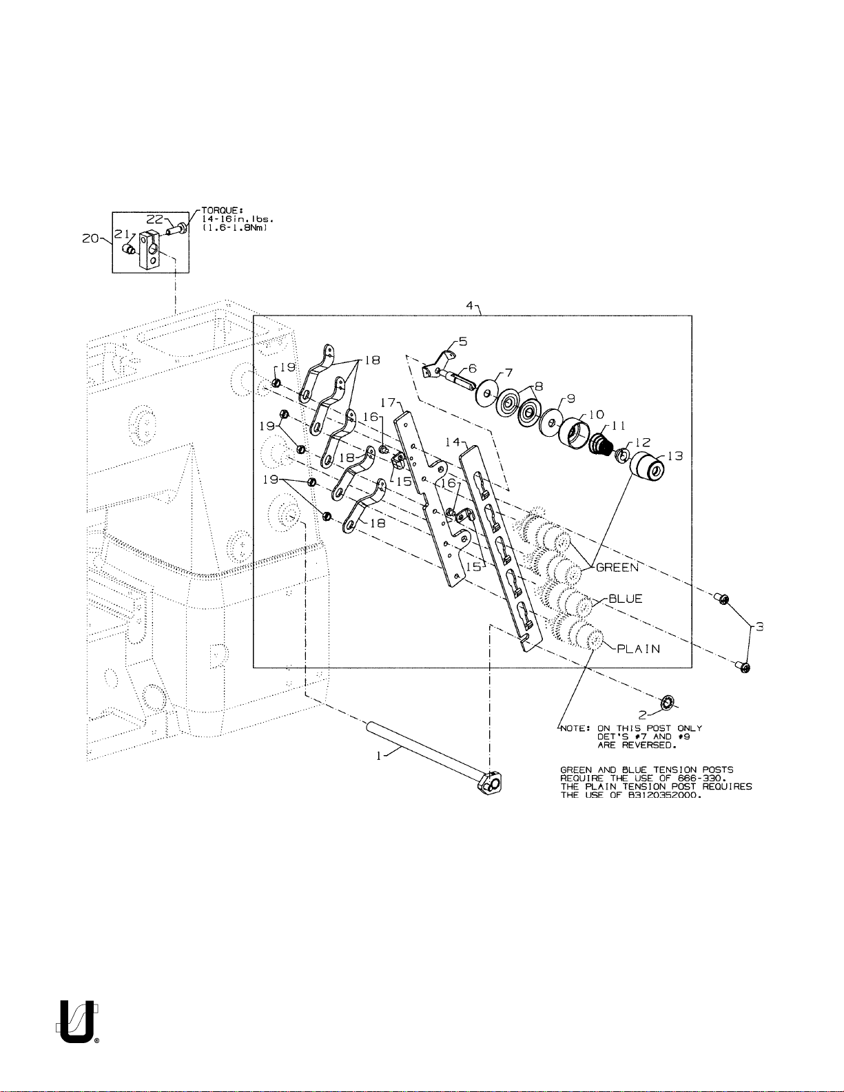
TENSION RELEASE & THREAD TENSION
Ref.
No.
1.
2.
3.
4.
5.
6.
7.
8.
9.
10.
11.
12.
13.
14.
15.
16.
17.
18.
19.
20.
21.
22.
.
Part No.
50392Z
660-283A
SS4120915SP
50392Y
57892K
56392G
B3120352000
-
666-330
B3126012000
B3120704000
56392H
11550209
-
B3103804000
-
B3121804000
B3112704000
50692G
-
56392M
-
56392R
50392W
50392AV
SS7090520SP
50392X
57865
NS6110420SP
50392BC
22875N
SS7121410TP
Description
Tension Needle Lever Assembly ..................................................................
Retainer Washer .........................................................................................
Screw, for tension assembly ........................................................................
5 Thread Tension Assembly ..........................................................................
Thread Tension Eyelet ...........................................................................
Tension Post ..........................................................................................
Tension Disc Felt ....................................................................................
Disc Felt ................................................................................................
Tension Disc ..........................................................................................
Tension Disc Felt ....................................................................................
Spring Shield .........................................................................................
Spring, needle (green) .........................................................................
Spring, spreader (blue) .........................................................................
Spring, looper (plain) ............................................................................
Ferrule, tension spring ...........................................................................
Knob, needle (green) ...........................................................................
Knob, spreader (blue) ..........................................................................
Knob, looper (plain) ..............................................................................
Tension Disc Separator .........................................................................
Guide, for tension disc separator ..........................................................
Screw, for guide ....................................................................................
Tension Bracket ....................................................................................
Lead-In Thread Guide ...........................................................................
Nut ........................................................................................................
Tension Release Lever Shaft Connection ....................................................
Base Spring Screw .................................................................................
Binder Screw .........................................................................................
Amt.
Req.
1
1
2
1
5
5
1
4
10
5
5
3
1
1
5
3
1
1
1
2
2
1
5
5
1
1
1
19
Page 20
20
Page 21

PRESSER FOOT LIFT
Ref.
No.
1.
2.
3.
4.
5.
6.
7.
8.
9.
10.
11.
12.
13.
14.
15.
16.
17.
18.
19.
20.
21.
22.
23.
24.
25.
26.
27.
28.
29.
30.
.
Part No.
11071602
11071701
660-1014
C50056B
50357AP
50335AF
SS6110610TP
50335AG
50335AH
SS8110422TP
660-739
50333P
22562
RE0500000K0
50381F
SD0790303SP
-
CE66
29476TK
SD0790303SP
50355AR
50381G
SS9151740CP
29476TT
SS6121010SP
NS6150310SP
50332V
SS6153040SP
SS6151920SP
-
CE66
50381
RO068190100
50381B
Description
Adjusting Screw, for spring ..........................................................................
Locking Nut .................................................................................................
"O" Ring .......................................................................................................
Spring Rod ..................................................................................................
Spring, for presser bar .................................................................................
Presser Bar ..................................................................................................
Screw, for guide plate ................................................................................
Guide Plate, for presser bar ........................................................................
Presser Bar Guide ........................................................................................
Set Screw ..............................................................................................
Oil Seal ........................................................................................................
Collar ..........................................................................................................
Screw ...................................................................................................
E Ring, for pin ..............................................................................................
Lever, for lifter, front ....................................................................................
Screw, for wire connector ..........................................................................
Loctite Adhesive, (not shown), for screw ....................................................
Rear Lifter Lever Assembly ..........................................................................
Screw ...................................................................................................
Wire Connector ..........................................................................................
Lifter Lever, rear ..........................................................................................
Hex Screw .............................................................................................
Stop Assembly ............................................................................................
Screw, for stopper ................................................................................
Hex Nut .................................................................................................
Stopper, for lifter lever ..........................................................................
Screw, for adjusting stopper .................................................................
Screw, for adjusting stopper .................................................................
Loctite Adhesive, (not shown), for screw ....................................................
Spring, for lifter lever ...................................................................................
"O" Ring .......................................................................................................
Lifter Lever Assembly ..................................................................................
Amt.
Req.
1
1
1
1
1
1
2
1
1
2
1
1
2
1
1
1
1
1
1
1
1
1
1
2
1
1
2
1
1
1
21
Page 22
22
Page 23

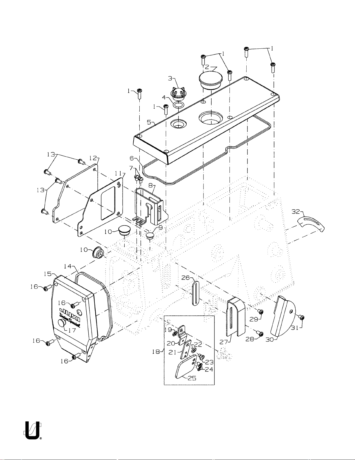
COVERS, UPPER ARM
Ref.
No.
1.
2.
3.
4.
5.
6.
7.
8.
9.
10.
11.
12.
13.
14.
15.
16.
17.
18.
19.
20.
21.
22.
23.
24.
25.
26.
27.
28.
29.
30.
31.
32.
.
Part No.
SS4121615SP
50393EU
B3530555000
660-212
50382FW
50382FZ
SS7120640SP
50317C
TA1050504R0
50393HB
50384L
50382GB
SS4120915SP
50382FY
50382FX
SS4121215SP
TA1100604R0
99682XCB
NS6620320SP
50383AE
50383AD
WZ0641510KP
SD0640323TP
SS6110610SL
99682XC3
50393EW
50382GA
SS4120915SP
SS4120615SP
50382GM
SS4120615SP
LA452
Description
Screw, for top cover ....................................................................................
Plug, for top cover .......................................................................................
Oil Sight Gauge, top ....................................................................................
"O" Ring, for oil sight gauge .........................................................................
Top Cover ...................................................................................................
Quad Ring, for top cover ............................................................................
Screw, for needle bar guard .......................................................................
Needle Bar Guard .......................................................................................
Plug, for bed ................................................................................................
Plug, for bed ................................................................................................
Gasket, for puller drive cover ......................................................................
Puller Drive Cover .......................................................................................
Screw, for puller drive cover .......................................................................
Quad Ring, for head cover .........................................................................
Head Cover ................................................................................................
Screw, for head cover .................................................................................
Plug, for head cover ...................................................................................
Protection Shield Assembly, for all styles except FS322E12 & FS332E12 ....
Nut ........................................................................................................
Bracket Holder ......................................................................................
Bracket .................................................................................................
Spring Washer .......................................................................................
Shoulder Screw .....................................................................................
Counter Sunk Head Screw ....................................................................
Protection Shield ..................................................................................
Rubber Gasket, for needle lever ................................................................
Cover, for thread take-up ...........................................................................
Screw, for thread take-up cover .................................................................
Screw, for thread cover ..............................................................................
Thread Cover ..............................................................................................
Screw, for thread take-up cover .................................................................
Label, direction of rotation .........................................................................
Amt.
Req.
6
1
1
1
1
1
2
1
1
2
1
1
4
1
1
4
1
1
1
1
1
1
1
2
1
1
1
1
1
1
1
1
23
Page 24
24
Page 25

LOWER MAIN SHAFT
Ref.
No.
1.
2.
3.
4.
5.
6.
7.
8.
9.
10.
11.
12.
13.
14.
15.
16.
17.
17A.
18.
.
Part No.
SS7660520SP
660-1062
50374
50321G
SS8661012TP
50342AX
SS8660612TP
50342BS
50335AK
29476UH
50322AL
50335BB
50322AG
50333A
SS8660612TP
660-934
50322AU
50322AT
SS8660410SP
Description
Shoulder Screw, for lower main shaft, right .................................................
Spring Washer .............................................................................................
Spacer, for pulley assembly ........................................................................
Pulley Assembly ..........................................................................................
Set Screw ..............................................................................................
Sprocket, for lower main shaft .....................................................................
Screw ....................................................................................................
Timing Belt ...................................................................................................
Retaining Ring, for ball bearing ...................................................................
Mainshaft Assembly, lower right ..................................................................
Ball Bearing, for lower main shaft ..........................................................
Retaining Ring ......................................................................................
Lower Main Shaft, right .........................................................................
Coupling, for lower main shafts ...................................................................
Screw ....................................................................................................
Oil Seal ........................................................................................................
Lower Main Shaft, left ..................................................................................
Lower Main Shaft, left, for FS322E12, FS332E12 ............................................
Screw ....................................................................................................
Amt.
Req.
1
1
1
1
2
1
2
1
1
1
1
1
1
1
4
1
1
1
2
25
Page 26

26
Page 27

LUBRICATION, OIL TUBING & OIL PUMP
Ref.
No.
1.
2.
3.
4.
5.
6.
7.
8.
9.
10.
11.
12.
13.
14.
15.
16.
17.
18.
19.
20.
21.
22.
23.
24.
25.
26.
27.
28.
29.
30.
31.
32.
33.
34.
35.
36.
37.
38.
39.
40.
41.
42.
43.
44.
45.
46.
47.
.
Part No.
50393HN
18-1470
50332S
34393D
50393EX
SS8660612TP
50393GB
50393GD
SS4091015SP
50393FR
50384
11843208
50393FV
SS7120710SP
29476US
NS6110310SP
50393KC
SQ1110402MZ
50393-27
50393KM
50393-407
50393-140
29476UT
50393KH
50393-70
50393KM
13765607
50393-140
50393-40
50393-170
50393KF
50393KM
50393HR
50393HL
50393FS
998-358F
53678N
SS4090815SP
50393HK
SS6151812TP
WS0631510KP
22571E
RM2871B
50393EB
50384A
50393FT
50393HJ
Description
Oil Pump Assembly, 2-stage .........................................................................
Screw .....................................................................................................
Spring, for plunger..................................................................................
Plunger ..................................................................................................
Collar, for oil pump .................................................................................
Screw ...............................................................................................
Oil Pump Housing, 2 Stage......................................................................
Oil Pump Housing, 2 Stage......................................................................
Screw, for oil filter cover................................................................................
Cover, for oil filter..........................................................................................
"O" Ring, for oil filter cover.............................................................................
Oil Filter.........................................................................................................
Oil Tube, for supply (1) ..................................................................................
Screw ...........................................................................................................
Oil Supply Assembly, upper ..........................................................................
Nut .........................................................................................................
Oil Gutter ...............................................................................................
Fitting .....................................................................................................
Oil Tube ..................................................................................................
Tube Retaining, spring ...........................................................................
Oil Tube ..................................................................................................
Oil Tube ..................................................................................................
Oil Supply Assembly, lower ...........................................................................
Tube Retaining, spring ...........................................................................
Oil Tube ..................................................................................................
Tube Retaining, spring ...........................................................................
"T" Connector .........................................................................................
Oil Tube ..................................................................................................
Oil Tube ..................................................................................................
Oil Tube ..................................................................................................
Oil Tube ..................................................................................................
Tube Retaining, spring ...........................................................................
Plug, for feed chamber ..........................................................................
Oil Tube, for suction ................................................................................
Oil Tube Holder .............................................................................................
Plastic Clip ....................................................................................................
Washer .........................................................................................................
Screw, for oil tube holder ..............................................................................
Felt ...............................................................................................................
Screw, for oil pan ..........................................................................................
Spring Washer ..............................................................................................
Screw, for oil drain plug ................................................................................
Cable Tie ......................................................................................................
Oil Pan ..........................................................................................................
"O" Ring ........................................................................................................
Oil Tube, for suction ......................................................................................
Oil Tube, for suction ......................................................................................
Amt.
Req.
1
2
2
2
1
2
1
1
3
1
1
1
1
2
1
1
1
1
1
4
1
1
1
2
1
5
2
1
1
1
1
3
1
1
1
1
1
1
1
6
6
1
2
1
1
1
1
27
Page 28

28
Page 29

LOOPER DRIVE
Ref.
No.
1.
2.
3.
4.
5.
6.
7.
8.
9.
10.
11.
12.
13.
14.
15.
16.
17.
18.
19.
20.
21.
.
-
Part No.
50313P
22652B10
22565
50309K
SS7120910SP
CE63
660-893
50344AM
660-455
50313J
SS7120910SP
50314J
50314E
50313M
22653J8
667J33
660-979
50342BJ
SS8660612TP
50342BK
SS8660612TP
50342BP
Description
Looper Holder .............................................................................................
Screw, for looper holder .......................................................................
Screw, for looper holder .......................................................................
Looper ........................................................................................................
Screw, for bearing housing .........................................................................
Three Bond Adhesive, (not shown), for screw ..............................................
Oil Seal, looper ............................................................................................
Bearing Housing Assembly, for looper drive ................................................
"O" Ring, for bearing housing assembly .......................................................
Looper Rocker Assembly .............................................................................
Screw, for retaining plate ............................................................................
Eccentric Retaining Plate ...........................................................................
Looper Avoid Adjusting Eccentric...............................................................
Looper Drive Assembly ................................................................................
Screw ....................................................................................................
Crank Pin ..............................................................................................
"O" Ring .................................................................................................
Sprocket, for looper driven .........................................................................
Screw ....................................................................................................
Sprocket, for looper drive ...........................................................................
Screw ....................................................................................................
Looper Drive Belt .........................................................................................
Amt.
Req.
1
1
1
1
3
1
1
1
1
2
1
1
1
1
1
2
1
2
1
2
1
29
Page 30

30
Page 31

NEEDLE GUARD
Ref.
No.
1.
2.
3.
4.
5.
6.
7.
8.
9.
10.
11.
12.
13.
14.
15.
16.
17.
.
Part No.
29476UJ
50373DA
SS8110422TP
50368W
50368T
SS8110422TP
50368V
50368E
50368A
50374
50354L
SS8110422TP
50325AF
50325AE
SS9090420TP
SS7060310SP
50325AJ
Description
Rear Needle Guard Drive Assembly ............................................................
Needle Guard Eccentric ......................................................................
Screw, for needle guard eccentric ................................................
Connecting Rod Assembly, for needle guard ......................................
Pivot Link ...............................................................................................
Screw .............................................................................................
Shaft, for needle guard ..................................................................
Washer .................................................................................................
Pivot Pin ................................................................................................
Washer ........................................................................................................
Coupling, for needle guard ........................................................................
Screw ....................................................................................................
Holder, for needle guard ............................................................................
Needle Guard, rear .....................................................................................
Screw, for rear needle guard ......................................................................
Screw, for front needle guard .....................................................................
Needle Guard, front ....................................................................................
Amt.
Req.
1
1
2
1
1
2
1
2
1
1
1
2
1
1
1
1
1
31
Page 32

32
Page 33

LOOPER THREAD TAKE-UP
Ref.
No.
1.
2.
3.
4.
5.
6.
7.
8.
9.
10.
11.
12.
13.
14.
15.
16.
17.
18.
19.
20.
.
Part No.
50357AM
SD0380551SL
50332AC
50347R
51959B
SS7060310SP
52958D
50357AN
50304N
SS6080410SP
SS6110610TP
29476UK
SS9111010SP
50383F
50304K
50386J
SD0630275SP
SS9111010SP
50323R
SS8660612TP
Description
Cast-Off Plate Assembly .............................................................................
Knurled Nut ...........................................................................................
Tension Spring .......................................................................................
Roll Pin ..................................................................................................
Tension Disc ..........................................................................................
Screw ....................................................................................................
Take-up Eyelet ......................................................................................
Cast-off Plate .......................................................................................
Retaining Finger ....................................................................................
Screw ....................................................................................................
Screw, for cast-off holder ............................................................................
Cast-Off Plate Holder Assembly ..................................................................
Screw, for collar bracket ......................................................................
Take-up Collar Bracket .........................................................................
Cast-Off Plate Holder ............................................................................
Washer .................................................................................................
Shoulder Screw, for cast-off plate holder .............................................
Screw, for collar bracket .............................................................................
Take-up Assembly .......................................................................................
Set Screw ..............................................................................................
Amt.
Req.
1
1
1
1
2
4
3
1
1
2
1
1
1
1
1
1
1
1
1
2
33
Page 34

34
Page 35

Ref.
No.
1.
2.
3.
4.
5.
6.
7.
8.
9.
10.
11.
12.
13.
14.
15.
16.
17.
18.
19.
20.
21.
22.
23.
24.
25.
26.
27.
28.
29.
30.
31.
32.
33.
34.
35.
36.
37.
.
Part No.
18-1432
50334BD
50334AW
50334BE
50334AX
50340D
SS8660612TP
SS7090530SP
50334Y
50334V
50334BH
50335AM
50335BA
50334BJ
50335AN
RO0681190100
50337J
SS4121215SP
29476YH
50337H
50337U
50337BD
SS7090610SP
B1647704000A
50387
SS7090610SP
50337S
SS8110422TP
50337L
SS6110650TP
50337R
SS8090710SP
SS6091022TP
SP0550271TP
50337M
50340F
SS8660612TP
FEED DRIVE MECHANISM
FOR
FS322C01, FS332CO1, FS335E41, FS335E42
FS322H01, FS332H01, FS332L01, FS332L21
Description
Screw .....................................................................................................
Hex Eccentric Stud .................................................................................
Drive Fork Assembly ................................................................................
Feed Bar Assembly .................................................................................
Drive Fork Assembly, right .......................................................................
Feed Eccentric, main .............................................................................
Screw ...............................................................................................
Screw .....................................................................................................
Oil Shield .................................................................................................
Oil Scraper .............................................................................................
Feed Bar Seal ..........................................................................................
Guide Plate, left, rear .............................................................................
Guide Plate, right, rear ...........................................................................
Feed Bar Seal ..........................................................................................
Guide Plate, front ...................................................................................
"O" Ring ..................................................................................................
Stem, for differential feed lever ..............................................................
Screw, for stem .......................................................................................
Differential Feed Lever Assembly ...........................................................
Differential Feed Lever .....................................................................
Stop ..................................................................................................
Plate, for differential feed lever .......................................................
Screw ...............................................................................................
Knob, for differential feed lever .......................................................
Screw ...............................................................................................
Screw .....................................................................................................
Collar .....................................................................................................
Screw ...............................................................................................
Coupling, for differential feed lever .......................................................
Screw ...............................................................................................
Collar, for differential feed lever ............................................................
Screw ...............................................................................................
Screw ...............................................................................................
Screw, for spring .....................................................................................
Spring, for differential feed lever ............................................................
Feed Eccentric, differential ...................................................................
Screw ..............................................................................................
Amt.
Req.
2
2
1
1
1
1
2
10
1
1
1
1
1
1
1
1
1
1
1
1
2
1
2
1
1
2
1
2
1
2
1
1
1
1
1
1
2
35
Page 36

36
Page 37

FEED DRIVE MECHANISM
FOR
FS322E12 & FS332E12
Ref.
No.
1.
2.
3.
4.
5.
6.
7.
8.
9.
10.
11.
12.
13.
14.
15.
16.
17.
18.
19.
20.
21.
22.
23.
24.
25.
26.
27.
28.
29.
30.
31.
32.
33.
34.
35.
36.
37.
38.
.
Part No.
18-1432
50334BD
50340F
SS8660612TP
50334AW
50334BE
50334AX
50340D
SS8660612TP
SS7090530SP
50334Y
50334V
50334BH
50335AM
50335BA
50334BJ
50335AN
50337S
SS8110422TP
50337L
SS6110650TP
50335AS
SS8110422TP
50336V
50332W
18-1445
NS6110530SP
RO068190100
50337Y
SS4121215SP
29476YH
50337H
50337U
50337BD
SS7090610SP
B1647704000A
50387
SS7090610SP
Description
Screw ..........................................................................................................
Hex Eccentric Stud ......................................................................................
Feed Eccentric, differential ........................................................................
Screw, for Feed Eccentric, differential..................................................
Drive Fork Assembly, left ..............................................................................
Feed Bar Assembly ......................................................................................
Drive Fork Assembly, right ............................................................................
Feed Eccentric, main ..................................................................................
Screw ....................................................................................................
Screw ..........................................................................................................
Oil Shield .....................................................................................................
Oil Scraper, front .........................................................................................
Feed Bar Seal ..............................................................................................
Guide Plate, left, rear .................................................................................
Guide Plate, right, rear ................................................................................
Feed Bar Seal ..............................................................................................
Guide Plate, front ........................................................................................
Collar ..........................................................................................................
Screw ....................................................................................................
Coupling, for differential feed lever ............................................................
Screw ....................................................................................................
Collar, for differential feed lever .................................................................
Screw ..........................................................................................................
Pin, for differential feed lever ......................................................................
Spring ..........................................................................................................
Spring Latch Screw .....................................................................................
Nut ..............................................................................................................
"O" Ring .......................................................................................................
Stem, for differential feed lever ..................................................................
Screw, for Stem ...........................................................................................
Differential Feed Lever Assembly ................................................................
Differential Feed Lever .........................................................................
Stop ......................................................................................................
Plate, for differential feed lever ............................................................
Screw ....................................................................................................
Knob, for differential feed lever ............................................................
Screw ....................................................................................................
Screw ..........................................................................................................
Amt.
Req.
2
2
1
2
1
1
1
1
2
10
1
1
1
1
1
1
1
1
2
1
1
1
2
1
1
1
1
1
1
1
1
1
2
1
2
1
1
2
37
Page 38

38
Page 39

FEED DRIVE MECHANISM
Ref.
No.
1.
2.
3.
4.
5.
6.
7.
8.
9.
10.
11.
12.
13.
14.
15.
16.
17.
18.
19.
20.
21.
22.
23.
24.
25.
26.
27.
28.
29.
30.
31.
32.
.
Part No.
TA0750404R0
22591A
50334BC
50368AD
50334BB
SS8110422TP
50337T
SS8110422TP
661-96
660-695
SS8661012TP
35036F
660-220
35036AZ
50634G
50335D
22894P
50333T
22894P
29476UF
660-980
50322AR
660-206
50336Y
SS8110422TP
50335
22714C
50355
50335A
50336S
661-35
22596H
Description
Plug, for eccentric shaft ..............................................................................
Screw, for eccentric shaft ...........................................................................
Eccentric Shaft ...........................................................................................
Washer, for eccentric shaft .........................................................................
Collar, for eccentric shaft ...........................................................................
Screw, for collar ....................................................................................
Collar, for eccentric shaft ...........................................................................
Screw, for collar ....................................................................................
Spring Washer .............................................................................................
"O" Ring, for bushing ....................................................................................
Screw, for bushing .......................................................................................
Bushing, for stitch adjusting shaft ................................................................
"O" Ring, for stitch adjusting shaft ................................................................
Brake Pad ....................................................................................................
Stitch Adjusting Shaft Assembly ...................................................................
Collar ..........................................................................................................
Screw ....................................................................................................
Collar ..........................................................................................................
Screw ....................................................................................................
Stitch Length Adjusting Rod Assembly .........................................................
"O" Ring, stitch control shaft ..................................................................
Shaft, for stitch control ..........................................................................
"O" Ring, for stitch control shaft ............................................................
Stitch Knob, indicator ...........................................................................
Screw .............................................................................................
Spring Retainer ...........................................................................................
Screw, for spring retainer ............................................................................
Spring ..........................................................................................................
Spring Holder ...............................................................................................
Stitch Control Lever .....................................................................................
Pin .........................................................................................................
Screw ....................................................................................................
Amt.
Req.
1
1
1
1
1
2
1
2
1
1
1
1
1
1
1
1
2
1
2
1
1
1
1
1
1
1
1
1
1
1
1
2
39
Page 40

40
Page 41

COVERS, LOWER BED
Ref.
No.
1.
2.
2A.
2B.
3.
3A.
4.
5.
6.
7.
8.
9.
10.
11.
11A.
12.
13.
14.
15.
15A.
16.
16A.
17.
18.
19.
20.
21.
22.
23.
24.
.
Part No.
18-1448
50301BH
50301BA
50301CH
50301BF
50301AZ
50303B
22726
95978
50345U
22839C
50382JR
50384K
50380KA
50380LA
50328
660-939
50336W
50382CP
50382CT
50382CS
50384E
SS7150740SP
SS6121212TP
37-70BLK
SS4120615SP
50382CL
50382CR
CE63
CO67D
22517
Description
Screw ..........................................................................................................
Cloth Plate, left, for FS332L01, FS332L21, FS322H01, FS332H01 .....................
Cloth Plate, left, for FS322C01, FS332C01, FS322E12, FS332E12 ....................
Cloth Plate, left, for FS335E41, FS332E42 ......................................................
Cloth Plate, right, for FS322H01, FS332H01, FS332L01, FS332L21, FS335E41,
FS335E42 .....................................................................................................
Cloth Plate, right, for FS322C01, FS332C01, FS322E12, FS332E12 ..................
Accoustic Pad ......................................................................................
Screw for Swing Plate, for FS332C01, FS332C01, FS335E41, FS335E42 .......
Spring Washer, for FS332C01, FS332C01, FS335E41, FS335E42......................
Swing Plate, for FS332C01, FS332C01, FS335E41, FS335E42 ..........................
Screw, for FS322H01, FS332H01, FS332L01, FS332L21 ....................................
Cover, for FS322H01, FS332H01, FS332L01, FS332L21 ...................................
Gasket, for FS322H01, FS332H01, FS332L01, FS332L21 ..................................
Throat Plate Support Complete, for FS335E41, FS335E42, FS322H01,
FS332H01, FS332L01, FS332L21, ...................................................................
Throat Plate Support Complete, for FS322C01, FS332C01, FS322E12,
FS332E12 .....................................................................................................
Diamond Pin .........................................................................................
Rubber Bumper, for throat plate support ..............................................
Dowel Pin, for throat plate support .......................................................
Cover for Feed Chamber, for FS322C01, FS332C01, FS322E12, FS332E12,
FS322H01, FS332H01, FS322L01, FS332L21, ..................................................
Cover for Feed Chamber, for FS335E41, FS335E42 .......................................
Gasket for FS322H01, FS332H01, FS332L01, FS332L21, FS322E12, FS332E12,
FS322C01, FS332C01 ...................................................................................
Gasket, for FS335E41, FS335E42 ...................................................................
Screw ..........................................................................................................
Screw, for feed chamber cover ..................................................................
Cover Blank, for FS335E41, FS335E42 ...........................................................
Screw ..........................................................................................................
Cover, rear, for feed chamber ....................................................................
Gasket ........................................................................................................
Three Bond Adhesive (not shown), for screw ...............................................
Cork ............................................................................................................
Screw, for bed .............................................................................................
Amt.
Req.
9-11
1
1
1
1
1
1
1
1
1
3
1
1
1
1
1
1
1
1
1
1
1
2
6
1
4
1
1
2
2
41
Page 42

42
Page 43

Ref.
No.
1.
1A.
2.
2A.
3.
4.
5.
6.
7.
8.
9.
10.
11.
12.
13.
14.
15.
16.
16A.
17.
18.
19.
20.
21.
22.
23.
24.
25.
26.
27.
28.
28A.
29.
30.
31.
32.
33.
34.
35.
36.
37.
38.
39.
40.
41.
42.
43.
44.
45.
46.
47.
48.
49.
Part No.
50382GK
50382CM
50382KF
50382KE
TA1100604R0
22541A
50336L
TA0620504R0
TA0750404R0
50336
660-974
22894C
999-216C
SS4151415SP
TA1100604R0
50393HB
22799AH
50332B
50357AC
35569J
22799AH
SS7120710SP
50382CJ
SS4121015SP
22799M
50393HU
25S
22839C
34703F2
34703E1
50382JB
50382FS
94
50332F
29476VX
50332A
41071G
22513D
50382CK
50363CH
22729D
50378S
SS9110543CP
660-1020
20
50382T
50393W
22519J
SS6120930TP
SS7090850SP
50382CG
50383G
22841U
COVERS, LOWER BED
Description
Quad Ring for end cover, for FS322E12, FS332E12 ........................................
Quad Ring for end cover, forFS335E41, FS335E42, FS322H01, FS332H01,
FS332L01, FS332L21 ......................................................................................
Left End Cover, for FS322E12, FS332E12 ........................................................
Left End Cover, for FS335E41, FS335E42, FS322H01, FS332H01, FS332L01,
FS332L21, .....................................................................................................
Plug, for FS322C01, FS332C01, FS322E12, FS332E12, .....................................
Screw, for FS322E12, FS332E12 .....................................................................
Ferrule, for FS322E12, FS332E12 ....................................................................
Plug for Left End Cover, for FS322E12, FS332E12 ...........................................
Plug, for FS322E12, FS332E12 ........................................................................
Bearing Thrust Collar, for FS322E12, FS332E12 ...............................................
Bearing, FS322E12, FS332E12 ..................................................................
Screw ....................................................................................................
Plug, for FS322E12, FS332E12 ........................................................................
Screw ...........................................................................................................
Plug, for FS335E41, FS335E42, FS322H01, FS332H01, FS332L01, FS332L21.
Plug ..............................................................................................................
Spring Latch Stud, for FS322C01, FS332C01, FS335E41, FS335E42, FS322H01,
FS332H01, FS322L01, FS332L21, ...................................................................
Support Block, for FS332L21, FS322E12, FS332E12, FS335E41, FS335E42,
FS322H01, FS332H01, FS332L01, FS332L21 .....................................................
Support Block, for FS322C01, FS332C01........................................................
Nut ...............................................................................................................
Spring Latch Stud .........................................................................................
Screw ...........................................................................................................
Cover, for drive belt .....................................................................................
Screw ...........................................................................................................
Stop Stud (used only with synchronizer)........................................................
Plug for right end non-synchronizer .............................................................
Screw, for FS322H01, FS332H01.....................................................................
Screw, for FS322H01, FS332H01.....................................................................
Holder, upper, for FS322H01, FS332H01........................................................
Hemmer, lower, for FS322H01, FS332H01 ......................................................
Swing Down Cover, for FS335E41, FS335E42 .................................................
Front Cover Assembly, for FS322E12, FS332E12 .............................................
Screw ....................................................................................................
Bracket ..................................................................................................
Front Cover Assembly, for FS322H01, FS332H01, FS332L01, FS332L21.............
Latch Spring ..........................................................................................
Nut .........................................................................................................
Screw ....................................................................................................
Swing Down Cover ................................................................................
Lever .....................................................................................................
Screw ....................................................................................................
Hinge .....................................................................................................
Screw ....................................................................................................
Rubber Bumper .....................................................................................
Washer ..................................................................................................
Stop, for front cover ...............................................................................
Rubber Bumper .....................................................................................
Screw ....................................................................................................
Screw ...........................................................................................................
Screw ...........................................................................................................
Dry Chamber Cover .....................................................................................
Gasket, for chamber cover .........................................................................
Machine Support Stud .................................................................................
Amt.
Req.
1
1
1
1
1/3
2
2
1
2
1
1
2
1
4
1
1
2
1
1
1
1
2
1
4
1
1
1
1
1
1
1
1
2
1
1
1/2
2
2
1
1
2
2
4
2
2
2
2
2
4
8
1
1
4
43
Page 44

44
Page 45

FRONT COVER ASSEMBLY
FOR
FS322C01, FS332C01
Ref.
No.
1.
2.
3.
4.
5.
6.
7.
8.
9.
10.
11.
12.
13.
14.
15.
16.
17.
18.
19.
20.
21.
22.
23.
24.
25.
26.
27.
28.
29.
30.
31.
32.
.
Part No.
29476VY
22882E
50368H
52864W
50364M
50332A
41071G
22513D
20
50382T
50393W
22519J
50363CH
22729D
50347P
97127
50378T
22894W
50382FT
22525A
50301AY
50382BB
77L
50364P
94
50303C
77F
77L
50343A
22517B
8372A
SS4121415SP
Description
Front Cover Assembly .................................................................................
Hex Head Screw ...................................................................................
Washer .................................................................................................
Folder Support Bracket .........................................................................
Mounting Bracket .................................................................................
Latch Spring ..........................................................................................
Nut ........................................................................................................
Screw ....................................................................................................
Washer .................................................................................................
Front Cover Stop ...................................................................................
Rubber Bumper .....................................................................................
Screw ....................................................................................................
Lever, front cover .................................................................................
Screw ....................................................................................................
Hinge Pin ...............................................................................................
Spring Washer .......................................................................................
Hinge ....................................................................................................
Set Screw ..............................................................................................
Swing Down Cover ...............................................................................
Screw ....................................................................................................
Cloth Plate ............................................................................................
Looper Shield ........................................................................................
Screw ....................................................................................................
Platform ................................................................................................
Screw ....................................................................................................
Edge Guide ..........................................................................................
Screw ....................................................................................................
Screw ....................................................................................................
Plate, for folder .....................................................................................
Screw ....................................................................................................
Washer .................................................................................................
Screw ....................................................................................................
Amt.
Req.
1
2
2
1
1
2
2
2
2
2
2
2
1
2
2
2
2
1
1
2
1
1
2
1
2
1
2
2
1
2
4
4
45
Page 46

46
Page 47

SEWING PARTS
FOR
FS322C01 & FS332C01
Ref.
No.
1.
1A.
2.
3.
3A.
4.
5.
6.
7.
8.
9.
10.
11.
11A.
12.
13.
14.
15.
16.
17.
18.
19.
20.
21.
22.
23.
24.
24A.
25.
26.
27.
.
Part No.
---------
--------SS8080310TP
50318AE40
50318AE56
SS6060440TP
50392G
--------34730H
91
97109
605
50330BN48
-
50330BN16
50330BN12
-
50330BN8
22799B
G65-181
50330BP16
96532
96671
52830G
57WD
187A
51959E
51430F
22565E
87
---------
---------
---------
--------SS7091110TP
Description
Needle Head, for 2 needle sewing comb., (see chart) ...............................
Needle Head, for 3 needle sewing comb., (see chart) ...............................
Screw, for Needle Head ........................................................................
Eyelet, per Needle Head, for 2 needle sewing comb. ...........................
Eyelet, per Needle Head, for 3 needle sewing comb. ...........................
Screw, for Eyelet ...................................................................................
Needle Thread Eyelet .................................................................................
Presser Foot Assembly, for sewing comb., (see chart) .................................
Presser Foot Shank ................................................................................
Screw .............................................................................................
Torsion Spring ........................................................................................
Screw ....................................................................................................
Presser Foot Bottom, for 50320V48 ........................................................
Presser Foot Bottom, for 50320V16 ........................................................
Presser Foot Bottom, for 50320U12 ........................................................
Presser Foot Bottom, for 50320U8 ..........................................................
Screw, for hinge ....................................................................................
Plunger .................................................................................................
Presser Foot Yielding Section ................................................................
Roll Pin ..................................................................................................
Roll Pin ..................................................................................................
Spring ...................................................................................................
Screw, for spring ...................................................................................
Screw, for plunger ................................................................................
Collar ....................................................................................................
Nut ........................................................................................................
Screw ....................................................................................................
Screw, for throat plate ................................................................................
Throat Plate, for 3 needle sewing comb., (see chart) ..................................
Throat Plate, for 2 needle sewing comb., (see chart) ..................................
Differential Feed Dog, for sewing comb., (see chart) .................................
Main Feed Dog, for sewing comb., (see chart) ...........................................
Screw, for feed dogs ...................................................................................
Amt.
Req.
1
1
3/4
1
1
1
1
1
1
1
1
1
1
1
1
1
1
1
1
1
1
1
1
1
1
1
1
2
1
1
1
1
2
LEDOMDAEHELDEEN
23D2-10C223SF23MA813058U023058X
04D2-10C223SF04MA8130521U0230501XX42743
84D2-10C223SF
84D3-10C223SF 84XX42743
65D3-10C223SF65MA81305
46D3-10C223SF46MA8130546XX42743
23D2-10
C233SF23MA813058U023058XX42743
04D2-10C233SF04MA8130521U0230501XX42743
84D2-10C233SF
84D3-10C233SF 84XX42743
65D3-10C233SF65MA81305
46D3-10C233SF46M
84MA8130584V02305
84MA8130584V0
A8130546XX42743
TOOFRESSERP
YLBMESSA
61V02305
2305
61V02305
47
ETALPTAORHTNIAMGODDEEF
X42743
ZA50305ZA62305
84XX42305
UA50305GA
65XX42743
ZA50305ZA62305
84XX42305
UA50305GA62305
65XX42743
GODDEEF
LAITNEREFFID
62305
Page 48

LEDOMDAEHELDEEN
TOOFRESSERP
YLBMESSA
ETALPTAORHTNIAMGODDEEF
GODDEEF
LAITNEREFFID
23D2-21E223SF23MA813058W023058D
04D2-21E223SF04MA8130521W0230501DT42843BB62305
84D2-21E223SF
84MA8130584X0230584DT42843
84D3-21E223SF
65D3-21E223SF65MA81305
61X02305
46D3-21E223SF46MA8130546DT42843
T42843
ZA50305
UA
50305FA62305
65DT42843
AB62305
48
Page 49

LEDOMDAEHELDEEN
TOOFRESSERP
YLBMESSA
ETALPTAORHTNIAMGODDEEF
GODDEEF
LAITNEREFFID
23D2-21E233SF23MA813058W023058D
04D2-21E233SF04MA8130521W0230501DT42843BB62305
84D2-21E233SF
84MA8130584X0230584DT42843
84D3-21E233SF
65D3-21E233SF65MA81305
61X02305
46D3-21E233SF46MA8130546DT42843
T42843
ZA50305
UA
50305FA62305
65DT42843
AB62305
49
Page 50

50
Page 51

SEWING PARTS
FOR
FS322E12 & FS332E12
Ref.
No.
1.
2.
3.
3a.
4.
5.
6.
7.
8.
9.
10.
11.
12.
13.
14.
15.
16.
16A.
17.
18.
19.
20.
21.
22.
23.
24.
25.
26.
26A.
27.
28.
28A.
29.
29A.
29B.
30.
30A.
31.
.
Part No.
---------SS5060410SP
50318AE40
50318AE56
SS6060440TP
50392G
---------52730T
91
51430F
22840A
97109
605
187A
57WD
52830G
50330CE16
-
50330CE48
50330CC8
-
50330CC12
73B
22799B
22738B
34830MA
99373A
95956
34830LA
G65-181
96532
50330CF
50330CD
87
-----------
-----------
-----------
-----------
-----------
-----------
----------SS7091110TP
Description
Needle Head, for sewing comb., (see chart) ..............................................
Screw ...................................................................................................
Eyelet, per needle head, for FE12-2D32, FE12-2D40 ..............................
Eyelet, per needle head, for FE12-2D48, FE12-3D48, FE12-3D56,
FE12-3D64 ...............................................................................................
Screw, for eyelet ...................................................................................
Needle Thread Eyelet .................................................................................
Presser Foot Assembly, for sewing comb., (see chart) .................................
Presser Foot Shank ................................................................................
Screw ....................................................................................................
Nut ........................................................................................................
Screw ....................................................................................................
Spring ...................................................................................................
Screw ....................................................................................................
Screw ....................................................................................................
Screw ....................................................................................................
Spring ...................................................................................................
Presser Foot Bottom, per presser foot, for FE12-3D56, FE12-3D64 .......
Presser Foot Bottom, per presser foot for, FE12-2D48, FE12-3D48 .......
Presser Foot Bottom, per presser foot for, FE12-2D32 .............................
Presser Foot Bottom, per presser foot for, FE12-2D40 .............................
Screw .............................................................................................
Screw ....................................................................................................
Screw ....................................................................................................
Tape Margin .........................................................................................
Screw ....................................................................................................
Washer .................................................................................................
Tape Guide ...........................................................................................
Plunger .................................................................................................
Roll Pin ..................................................................................................
Yielding Section, for sewing comb., FE12-2D48, FE12-3D48, FE12-3D56,
FE12-3D60, FE12-3D64 ....................................................................................
Yielding Section, for sewing comb., FE12-2D32, FE12-2D40 ..........................
Screw, for throat plate ................................................................................
Throat Plate, for sewing comb., (see chart).................................................
Throat Plate, for sewing comb., (see chart) ................................................
Differential Feed Dog, for sewing comb., (see chart)..................................
Differential Feed Dog, for sewing comb., (see chart)..................................
Differential Feed Dog, for sewing comb., (see chart) .................................
Main Feed Dog, for sewing comb., (see chart) ...........................................
Main Feed Dog, for sewing comb., (see chart) ...........................................
Screw, for feed dogs ...................................................................................
Amt.
Req.
1
4-6
1
1
1
1
1
1
1
1
1
1
1
1
1
1
1
1
1
1
1
1
1
1
1
1
1
1
1
1
2
1
1
1
1
1
1
1
2
51
Page 52

52
Page 53

SEWING PARTS
FOR
FS335E41 & FS335E42
Ref.
No.
1.
2.
3.
4.
5.
6.
7.
8.
9.
10.
11.
12.
13.
14.
15.
16.
17.
18.
19.
20.
21.
22.
23.
24.
25.
26.
27.
28.
29.
.
Part No.
50318AA56
-
50318AA64
SS5060410SP
50318AE56
660-1046
SS8080310TP
50392G
50320BF64
G57730GB
91
G57730GD
6-25-55
50330BH64
34730A
G57730GC
22716
96651
39568J
87
50324DB56
-
50324DC64
SS7091110TP
50305BS
50326BL
29480AWR
25
201C
25D
57864B
50389B
-
21210
51493AF
Description
Needle Head, for sewing comb., (see chart) ..............................................
Needle Head, for sewing comb., (see chart) ..............................................
Round Head Screw ...............................................................................
Eyelet, needle head, for sewing comb. (see chart) ..............................
Pin .........................................................................................................
Screw ....................................................................................................
Eyelet ..........................................................................................................
Presser Foot Assembly .................................................................................
Shank ....................................................................................................
Screw ....................................................................................................
Torsion Spring ........................................................................................
Pin (01.5 x 10.5) ......................................................................................
Presser Foot Bottom ...............................................................................
Yielding Section ....................................................................................
Plate ......................................................................................................
Screw ....................................................................................................
Roll Pin ...................................................................................................
Pressure Spring ......................................................................................
Screw, for throat plate .................................................................................
Throat Plate, for sewing comb., (see chart) .................................................
Throat Plate, for sewing comb., (see chart) .................................................
Screw, for feed dogs ...................................................................................
Main Feed Dog ............................................................................................
Differential Feed Dog ..................................................................................
Folder Kit ......................................................................................................
Gauge Screw Assembly ........................................................................
Gauge Screw ..................................................................................
Washer ............................................................................................
Washer Plate .........................................................................................
Folder ....................................................................................................
Looper Collar (not shown) .....................................................................
Isolator ..................................................................................................
Amt.
Req.
1
1
1
1
3
4
1
1
1
1
1
1
1
1
1
1
1
1
2
1
1
2
1
1
1
2
2
2
1
1
1
1
LEDOMDAEHELDEEN
23D2-21E233SF23MA813058W023058D
04D2-21E233SF04MA8130521W0230501DT42843BB62305
84D2-21E233SF
84MA8130584X0230584DT42843
84D3-21E233SF
65D3-21E233SF65MA81305
46D3-21E233SF46MA8130546DT42843
TOOFRESSERP
YLBMESSA
61X02305
ETALPTAORHTNIAMGODDEEF
T42843
65DT42843
ZA50305
UA
50305FA62305
53
GODDEEF
LAITNEREFFID
AB62305
Page 54

LEDOMDAEHELDEEN
TOOFRESSERP
YLBMESSA
ETALPTAORHTNIAMGODDEEF
GODDEEF
LAITNEREFFID
23A2-10H223SF
23MA81305
23C2-10H223SF8F42743
5
HA0230
04A2-10H223SF
04MA81305
04C2-10H223SF01F42743
223SF
H223SF84F42743
H223SF
84A2-10H
84C2-10H223SF84F42743
84A3-10H223SF 84LB42305
84B3-10H223SF 84SB42305
84C3-10
65A3-10H223SF
65B3-10H223SF 65SB42305
65C3-10H223SF65F42743
46A3-10
46B3-10H223SF 46SB42305
46C3-10H223SF46F42743
23A2-10H233SF
23C2-10H233SF8F42743
04A2-10H233SF
04C2-10H233SF01F42743
84MA8130584T02305
65MA81305
06T02305
46MA81305
23MA81305
HA02305
04MA81305
23LB42305
04LB42305
84LB42305
65LB42305
46LB42305
MB50305YA62305
23LB42
305
04LB42305
84A2-10H233SF
84C2-10H233SF84F42743
84A3-10H233SF 84LB42305
84B3-10H233SF 84SB42305
84C3-10H233SF84F42743
H233SF
65A3-10
65B3-10H233SF 65SB42305
65C3-10H233SF65F42743
46A3-10H233SF
46B3-10H233SF 46SB42305
46C3-10H233SF46F42743
84MA8130584T0230
65MA81305
46MA81305
5
06T02305
84LB42305
65LB42305
46LB4
2305
54
Page 55

LEDOMDAEHELDEEN
TOOFRESSERP
YLBMESSA
ETALPTAORHTNIAMGODDEEF
GODDEEF
LAITNEREFFID
23A2-10L233SF
23MA81305
23C2-10L233SF 23MB42305
5
HA0230
04A2-10L233SF
04MA81305
04C2-10L233SF 04JB42305
84A
3-10L233SF
84B3-10L233SF 84RB42305
84C3-10L233SF 84MB42305
65A3-10L233SF
65B3-10L233SF 65RB42305
65C3-10L233SF 65MB42305
46A3-10L233SF
33SF 46RB42305
46B3-10L2
46C3-10L233SF 46MB42305
65A3-12L233SF
65B3-12L233SF 65RB42305
84MA8130584T02305
65MA81305
46MA81305
06T02305
65MA81305
23NB42305
04KB42305
84NB42305
NA50305EA62305
65NB42305
46NB42305
65NB42305
65C3-12L233SF 65MB42305
46A3-12L233SF
46B3-12L233SF 46RB42305
46C3-12L233SF 46MB42305
46MA81305
55
VA50305XA62305
46NB42305
Page 56

56
Page 57

SEWING PARTS
FOR
FS322H01, FS332H01, FS332L01, FS332L21
Ref.
No.
1.
1A.
2.
3.
3A.
4.
5.
6.
7.
8.
9.
10.
11.
12.
12A.
13.
14.
15.
16.
17.
17A.
18.
19.
20.
21.
22.
23.
24.
.
Part No.
------
-----SS8080310TP
50318AE40
50318AE56
S5060410TP
50392G
-----G65-134
91
79633
605
22716A
50397A16
-
50397A48
50397C
G50-266
57830A
50330BL16
6-25-55
-------
------87
22561
27-435BLK
23195
-------
------SS7091110TP
Description
Needle Head, for two needle machines (see chart) ...................................
Needle Head, for three needle machines (see chart) ................................
Screw ....................................................................................................
Eyelet, per needle head, for sewing comb., .........................................
Eyelet, per needle head, for sewing comb., .........................................
Screw ...................................................................................................
Needle Thread Eyelet .................................................................................
Presser Foot, for sewing comb., (see chart) .................................................
Presser Foot Shank ................................................................................
Screw ....................................................................................................
Spring ...................................................................................................
Screw ....................................................................................................
Screw ....................................................................................................
Stitch Tongue, per presser foot, for gauges 5.6, 6.4 ..............................
Stitch Tongue, per presser foot, for gauge 4.8 ......................................
Stitch Tongue, per presser foot, for gauges 3.2, 4.0 ..............................
Bushing .................................................................................................
Yielding Section ....................................................................................
Presser Foot Bottom ..............................................................................
Drill Rod .................................................................................................
Throat Plate, for sewing comb., (see chart) ................................................
Throat Plate, for sewing comb., (see chart) ................................................
Screw, for throat plate ................................................................................
Screw, for guide ..........................................................................................
Washer, for screw ........................................................................................
Guide ..........................................................................................................
Differential Feed Dog, for sewing comb., (see chart) .................................
Main Feed Dog, for sewing comb., (see chart) ...........................................
Screw, for feed dogs ...................................................................................
Amt.
Req.
1
1
3/4
1
1
1
1
1
1
1
1
1
1
1
1
1
2
1
2
3
1
1
2
1
2
1
1
1
2
57
Page 58
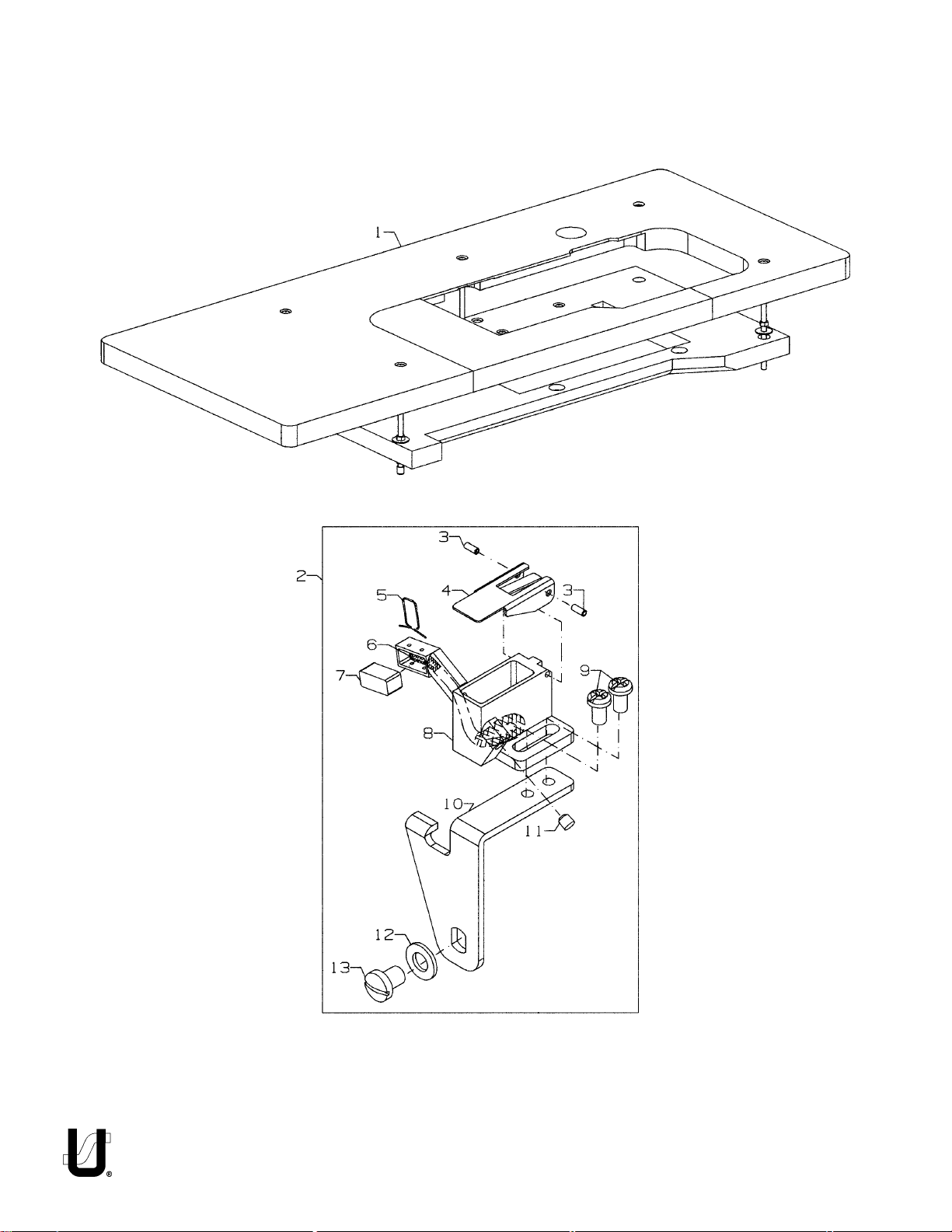
58
Page 59

Ref.
No.
1.
2.
3.
4.
5.
6.
7.
8.
9.
10.
11.
12.
13.
.
Part No.
21371AAE48
29476RZ
PS0160042KH
50393JD
50393GS
CQ202000000
50393GK
50393JC
SS4090615SP
50393GP
50393GG
WP0531000SD
SS4120615SP
TABLING ANDNEEDLE DIPPER ASSEMBLY
(EXTRA SEND CHARGE)
FOR
FS322C01, FS332CO1, FS335E41, FS335E42
FS322H01, FS332H01, FS332L01, FS332L21
Description
Table Board .................................................................................................
Needle Dipper Assembly ............................................................................
Roll Pin ..................................................................................................
Needle Dipper Cover ...........................................................................
Wire, for needle dipper .........................................................................
Oil Wick, for needle dipper ...................................................................
Felt, for needle dipper ..........................................................................
Needle Dipper ......................................................................................
Screw, for needle dipper ......................................................................
Silicone Oil Tank Holder .........................................................................
Plug .......................................................................................................
Washer .................................................................................................
Screw, for needle dipper holder............................................................
Amt.
Req.
1
1
2
1
1
1
1
1
2
1
1
1
1
59
Page 60

60
Page 61

TABLING (EXTRA SEND CHARGE)
FOR
FS322E12 & FS332E12
Ref.
No.
1.
2.
3.
4.
5.
6.
7.
8.
.
Part No.
21371AAG48
29480WR1
SS5091020SP
50383AC
11960101
11960002
NS6090310SP
90561K
Description
Table Board .................................................................................................
Waste Removal Kit ......................................................................................
Screw ....................................................................................................
Bracket .................................................................................................
Waste Chute .........................................................................................
Chute Extension ....................................................................................
Nut ........................................................................................................
Wood Screw .........................................................................................
Amt.
Req.
1
1
3
1
1
1
3
2
61
Page 62

62
Page 63

ACCESSORIES
Ref.
No.
1.
2.
3.
4.
5.
6.
7.
8.
9.
10.
11.
12.
13.
14.
15.
16.
17.
18.
19.
20.
20A.
21.
22.
23.
24.
25.
26.
27.
28.
29.
.
Part No.
11969557
29480AHU
50322L
50392C
482C
22894C
50322H
50364A
22728
90561K
29480ASR
23439L
188D
23439F
51-651BLK
907
SS6151920SP
50392D
22852G
SS7110510SP
25CC
23432B
421D34
660-264
TT17
128GBS075/029
35095B
G21201
660-240
28604R
Description
Thread Stand ...............................................................................................
Tape Reel Assembly, for FS322C01, FS332C01 .............................................
Support Shaft ........................................................................................
Tape Disc ..............................................................................................
Collar ....................................................................................................
Screw .............................................................................................
Shaft .....................................................................................................
Holder ...................................................................................................
Thumb Screw ........................................................................................
Wood Screw .........................................................................................
Strip Tension Kit, for FS322C01, FS332C01 .....................................................
Tension Assembly ..................................................................................
Screw .............................................................................................
Adjustable Pin ................................................................................
Guide .............................................................................................
Nut ..................................................................................................
Screw ....................................................................................................
Spacer ..................................................................................................
Screw ....................................................................................................
Screw ....................................................................................................
Screw ....................................................................................................
Folder Clamp ........................................................................................
Chain ..........................................................................................................
S-Hook .........................................................................................................
Wrench, for FS322E12, FS332E12, FS335E41, FS335E42..................................
Needles (package of 10) ............................................................................
Isolator ........................................................................................................
Screw Driver, for needle head ....................................................................
Thread Tweezer ...........................................................................................
Oil (1 pint) ....................................................................................................
Amt.
Req.
1
1
1
1
1
2
1
1
1
3
1
1
2
2
1
2
2
2
1
2
2
1
1
2
1
1
4
1
1
2
63
Page 64

64
Page 65

VACUUM TUBE ASSEMBLY AND PNEUMATIC CONTROL (EXTRA SEND CHARGE)
FOR
FS322E12 & FS332E12
Ref.
No.
1.
2.
3.
4.
5.
6.
7.
8.
9.
10.
11.
12.
13.
14.
15.
16.
.
Part No.
29480WR2
50394AH
999-175DA
50373CR1
41358
J87J
50373DJ
88D
29480ASU
90561K
99683CP
671F81A
671FD42
671F88
29480ARN
99675QB800
Description
Pneumatic Waste Removal Kit ....................................................................
Vacuum Tube Assembly .......................................................................
Fitting .............................................................................................
Bracket ...........................................................................................
Washer ...........................................................................................
Screw .............................................................................................
Tube, for vacuum ...........................................................................
Screw ....................................................................................................
Pneumatic Control Kit ...........................................................................
Wood Screw ...................................................................................
Mounting Bracket ...........................................................................
Elbow Fitting - 6mm x 1/2" NPT .........................................................
Filter/Regulator Assembly ..............................................................
Barb Fitting .....................................................................................
Treadle Switch Assembly .............................................................................
Spiral Plastic Hose .......................................................................................
Amt.
Req.
1
1
1
1
2
2
1
2
1
2
1
1
1
1
1
1
65
Page 66

66
Page 67

UNDER BED THREAD TRIMMER
FOR
FS322E12 & FS332E12
Ref.
No.
1.
2.
3.
4.
5.
6.
7.
8.
9.
10.
11.
12.
13.
14.
15.
16.
17.
18.
19.
20.
21.
22.
23.
24.
25.
26.
27.
28.
29.
30.
31.
32.
33.
34.
35.
36.
37.
38.
39.
40.
41.
42.
43.
44.
45.
46.
47.
.
Part No.
50394AK
50378U
41358
J87J
50373CR1
88D
50349B
50373DF
22743
34771PA
22729
99316G
34770AH
34750CA
22729E
51250C
22797
34749A
50373D
97010D
50373B
50373E
22894W
34334D
22565C
99364
50373DE
96531
99371G
50373A
50373G
22585
136
50373DH
50373K
999-313N
22894E
22894Y
99371G
50373CB
22894AD
50373CD
50368AA
999-313F
22894W
50373CC
22766
Description
Chip Chute Assembly ..................................................................................
Chip Chute ...........................................................................................
Washer .................................................................................................
Screw ....................................................................................................
Bracket .................................................................................................
Screw ..........................................................................................................
Undertrimmer Assembly ..............................................................................
Edge Guide ..........................................................................................
Screw .............................................................................................
Upper Knife Holder ................................................................................
Screw .............................................................................................
Screw ....................................................................................................
Upper Knife ...........................................................................................
Lower Knife Holder ................................................................................
Screw .............................................................................................
Nut ........................................................................................................
Screw ....................................................................................................
Lower Knife ...........................................................................................
Collar ....................................................................................................
Spring ...................................................................................................
Shaft .....................................................................................................
Collar ....................................................................................................
Screw .............................................................................................
Thrust Collar ..........................................................................................
Screw .............................................................................................
Screw ....................................................................................................
Undertrimmer Housing ..........................................................................
Pin ..................................................................................................
Screw .............................................................................................
Bushing, left ....................................................................................
Bracket ...........................................................................................
Screw ....................................................................................................
Screw ..........................................................................................................
Lever Clamp ...............................................................................................
Link Pin ........................................................................................................
Needle Bearing ...........................................................................................
Screw ..........................................................................................................
Screw ..........................................................................................................
Screw ..........................................................................................................
Eccentric, for knife drive .............................................................................
Screw ....................................................................................................
Washer ........................................................................................................
Connecting Arm, for knife drive ..................................................................
Needle Bearing ....................................................................................
Screw ....................................................................................................
Retaining Plate ...........................................................................................
Screw ..........................................................................................................
Amt.
Req.
1
1
2
2
1
2
1
1
1
1
1
1
1
1
1
1
1
1
1
1
1
1
1
2
4
1
1
2
1
1
2
1
1
1
1
2
1
1
1
1
2
2
1
1
1
1
2
67
Page 68

68
Page 69

LOWER ROLLER ASSEMBLY
FOR
FS335E41 & FS335E42
Ref.
No.
1.
2.
3.
4.
5.
6.
7.
8.
9.
10.
11.
12.
12A.
13.
.
Part No.
29476PV
-
29476PJ
376
AS22D
SS1110710SP
50378E
C50078AF5
C50078AF10
C50078U
22894W
660-330
6042A
50375D
C50076
C50074
Description
Lower Roller Assembly, for styles FS335E41 ..................................................
Lower Roller Assembly, for styles FS335E42 ..................................................
Screw ....................................................................................................
Screw ....................................................................................................
Screw ....................................................................................................
Feed Plate ............................................................................................
Shim ......................................................................................................
Shim ......................................................................................................
Bearing Block ........................................................................................
Set Screw ..............................................................................................
Retaining Ring ......................................................................................
Washer .................................................................................................
Puller Roller, for styles FS335E41 .............................................................
Lower Roller (smooth), for styles FS335E42.............................................
Pin .........................................................................................................
Amt.
Req.
1
1
4
1
1
1
2
2
2
2
2
3
1
1
1
69
Page 70

70
Page 71

UPPER ROLLER ASSEMBLY
FOR
FS335E41 & FS335E42
Ref.
No.
1.
2.
3.
4.
5.
6.
7.
8.
9.
10.
11.
12.
13.
14.
15.
16.
17.
17A.
18.
19.
20.
21.
22.
23.
24.
25.
26.
27.
.
Part No.
29476UW
-
29476ST
SS9111010SP
WS0510002KP
53634C
34778D
34774
34778A
11638M
SS7110410SP
C50077K
34778C
50377AE
661-261
50386B
50377H
661-149
50375Y
50375V
50377AC
50377AD
96278
22892C
50377AJ
SS6151220SP
SS8151150SP
SS8110422TP
50377AL
50355AS
Description
Upper Roller Assembly, for styles FS335E41 ..................................................
Upper Roller Assembly, for styles FS335E42 ..................................................
Hex Screw .............................................................................................
Lock Washer .........................................................................................
Washer .................................................................................................
Guide Plate ..........................................................................................
Shaft .....................................................................................................
Bushing .................................................................................................
Stud Nut ................................................................................................
Screw ...................................................................................................
Washer .................................................................................................
Bushing .................................................................................................
Disc .......................................................................................................
Cup Spring ............................................................................................
Washer .................................................................................................
Lever Assembly .....................................................................................
"O" Ring .................................................................................................
Roller Assembly, for styles FS335E41 ......................................................
Roller Assembly (smooth), for styles FS335E42 .......................................
Roller Guard .........................................................................................
Bushing .................................................................................................
"E" Ring ..................................................................................................
Shoulder Screw .....................................................................................
Feed Roller Yolk Assembly .....................................................................
Screw .............................................................................................
Screw .............................................................................................
Set Screw ........................................................................................
Stop Lever ............................................................................................
Connector, for Presser Foot Lift ...................................................................
Amt.
Req.
1
1
2
1
1
1
1
1
2
4
1
1
1
2
1
1
2
1
1
1
1
1
1
1
1
1
3
1
1
71
Page 72

72
Page 73

PULLER LIFTER ASSEMBLY
FOR
FS335E41 & FS335E42
Ref.
No.
1.
2.
3.
4.
5.
6.
7.
8.
9.
10.
11.
12.
13.
14.
15.
16.
17.
18.
19.
20.
21.
22.
23.
24.
25.
.
Part No.
50377VA
SS6151440SP
29476UX
59477
35733G
660-212
50377L
50377C
50344AT
50377D
SS8150710SP
SS8120410SP
50337AM
50377AF
96529
50377M
SS8151150SP
NS6110310SP
SS7112420SP
50377AM
50377Y
SS6121220TP
50377T
RO068190100
50377G
Description
Lever, lifter front ..........................................................................................
Screw ....................................................................................................
Puller Lifter Assembly ...................................................................................
Regulator ..............................................................................................
Nut ........................................................................................................
"O" Ring .................................................................................................
Spring ...................................................................................................
Lever, lifter ............................................................................................
Bushing .................................................................................................
Bracket, for roller lifter ...........................................................................
Set Screw ........................................................................................
Set Screw ........................................................................................
Bumper ...........................................................................................
Pin ..................................................................................................
Pin ..................................................................................................
Lifter ......................................................................................................
Screw .............................................................................................
Nut ..................................................................................................
Screw .............................................................................................
Bar, roller presser ...................................................................................
Guide Pin ..............................................................................................
Screw ..........................................................................................................
Bushing, lifter link .........................................................................................
"O" Ring .......................................................................................................
Lever, Puller Lifter ........................................................................................
Amt.
Req.
1
1
1
1
1
1
1
1
2
1
1
1
2
1
1
1
1
1
1
1
1
2
1
1
1
73
Page 74

74
Page 75

PULLER DRIVE ASSEMBLY
FOR
FS335E41 & FS335E42
Ref.
No.
1.
2.
3.
4.
5.
6.
7.
8.
9.
10.
11.
12.
13.
14.
15.
16.
17.
18.
19.
20.
21.
22.
23.
24.
.
Part No.
29476SP
50377F
660-893
50377S
50377E
SS8110510SP
50377U
50377P
TA1450404R0
SS7121610SP
50377Z
50377AA
SS2090620SP
50386
50377AB
SS8660612TP
660-1090
50377J
SS6122030SP
50344AP
660-303
NS6120480SP
WP0501046SC
660-1089
Description
Puller Drive Assembly ..................................................................................
Roller Driving Arm ..................................................................................
Seal .......................................................................................................
Bushing .................................................................................................
Lever, puller drive .................................................................................
Set Screw ..............................................................................................
Housing, puller drive .............................................................................
Bushing .................................................................................................
Rubber Plug ..........................................................................................
Screw ..........................................................................................................
Connecting Rod Eccentric Assembly .........................................................
Connecting Rod ...................................................................................
Screw ....................................................................................................
Washer .................................................................................................
Eccentric ..............................................................................................
Screw .............................................................................................
Quad Ring ...................................................................................................
Roller Drive Link Assembly ...........................................................................
Screw ....................................................................................................
Bushing, link ..........................................................................................
Bearing .................................................................................................
Nut ........................................................................................................
Washer .................................................................................................
Thrust Washer ........................................................................................
Amt.
Req.
1
1
1
1
1
1
1
1
1
4
1
1
2
1
1
2
1
1
2
2
2
2
4
4
75
Page 76

NUMERICAL INDEX OF PARTS
Part No. Page No.
11071602 .....21
11071701 .....21
11550209 .....19
11638M .....71
11843208 .....27
11960002 .....61
11960101 .....61
11969557 .....63
12124202 .....17
128GBS075/029 .....63
136 .....67
13765607 .....27
18-1432 .....35, 37
18-1445 .....37
18-1448 .....41
18-1470 .....27
187A .....45, 47, 51
188D .....63
20 .....43, 45
201C .....53
21210 .....53
21371AAE48 .....59
21371AAG48 .....61
22513D .....43, 45
22517 .....41
22519J .....43, 45
22525A .....45
22541A .....43
22561 .....57
22562 .....21
22565 .....29
22565C .....67
22565E .....47
22571E .....27
22571L .....9
22585 .....67
22591A .....39
22596H .....39
22652B10 .....29
22653J8 .....29
22704 .....45
22714C .....39
22716 .....53
22716A .....57
22726 .....41
22728 .....63
22729 .....67
22729D .....43, 45
22729E .....67
22738B .....51
22743 .....67
22766 .....67
22799AH .....43
22799B .....47, 51
22799M .....43
Part No. Page No. Part No. Page No.
22839C .....41, 43
22840A .....51
22841U .....43
22852G .....63
22875N .....19
22882E .....45
22892C .....71
22894AD .....67
22894C .....33, 43, 63
22894E .....67
22894P .....39
22894W .....45 , 67, 69
22894Y .....67
23195 .....57
23432B .....63
23439F .....63
23439L .....63
25 .....53
25CC .....63
25D .....53
25S .....43
27-435BLK .....57
28604R .....63
29126FW .....15
29475CG .....17
29476PJ .....69
29476PV .....69
29476RZ .....59
29476SP .....75
29476ST .....71
29476TC .....11
29476TK .....21
29476TT .....21
29476UF .....39
29476UH .....25
29476UJ .....31
29476UM .....35, 37
29476US .....27
29476UT .....27
29476UW .....71
29476UX .....73
29476VX .....43
29476VY .....45
29480AHU .....63
29480ARN .....65
29480ASR .....63
29480ASU .....65
29480AWR .....53
29480WR1 .....61
29480WR2 .....65
34334D .....67
34393D .....27
34703E1 .....43
34703F2 .....43
34730A .....53
34730H .....47
34749A .....67
34750CA .....67
34770AH .....67
34771PA .....67
34774 .....71
34778A .....71
34778C .....71
34778D .....71
34830LA .....51
34830MA .....51
35036AB .....9
35036AZ .....39
35036F .....39
35095B .....63
35569J .....43
35733G .....73
36271A .....17
37-70BLK .....41
376 .....69
39568J .....53
402 .....19
41071G .....43, 45
41358 .....65, 67
421D34 .....63
482C .....63
50301AY .....45
50301AZ .....41
50301BA .....41
50301BF .....41
50301BH .....41
50301CH .....41
50303A .....45
50303B .....41
50304K .....33
50304N .....33
50305BM .....57
50305BS .....53
50309F .....29
50309K .....29
50313 .....29
50313J .....29
50313M .....29
50313P .....29
50314E .....29
50314F .....29
50317B .....11
50317C .....23
50318AA56 .....53, 57
50318AA64 .....53
50318AE40 .....47, 51, 57
50318AE56 .....47, 51, 53, 57
50318Z40 .....57
50320AT .....57
50320BF64 .....53
Part No. Page No.
50320T60 .....57
50321F .....13
50321G .....25
50322AF .....13
50322AG .....25
50322AJ .....25
50322AK .....25
50322AL .....25
50322AR .....39
50322AT .....25
50322AU .....25
50322H .....63
50322L .....63
50323B .....33
50323P .....11
50323R .....33
50324DB56 .....53
50324DC64 .....53
50325AD .....31
50325AE .....31
50325AF .....31
50325AJ .....31
50326AY .....57
50326BL .....53
50328 .....41
50330BH64 .....53
50330BL16 .....57
50330BN12 .....47
50330BN16 .....47
50330BN48 .....47
50330BN8 .....47
50330BP16 .....47
50330CC12 .....51
50330CC8 .....51
50330CD .....51
50330CE16 .....51
50330CF .....51
50330CZ .....9
50330EE48 .....51
50332A .....43, 45
50332AC .....33
50332B .....43
50332F .....43
50332S .....27
50332U .....9
50332V .....21
50332W .....37
50333A .....25
50334AW .....35, 37
50334AX .....35, 37
50334BB .....39
50334BC .....39
50334BD .....35, 37
50334BE .....35, 37
50334BH .....35, 37
76
Page 77

NUMERICAL INDEX OF PARTS
Part No. Page No.
50334BJ .....35, 37
50334J .....35
50334V .....35, 37
50334Y .....35, 37
50335 .....39
50335A .....21, 39
50335AF .....21
50335AG .....21
50335AH .....21
50335AK .....25
50335AM .....35, 37
50335AN .....35, 37
50335AS .....37
50335AW .....15
50335BA .....35, 37
50335BB .....25
50335BD .....13
50335D .....39
50336 .....43
50336L .....43
50336S .....39
50336V .....37
50336W .....41
50336Y .....39
50337AM .....73
50337H .....35, 37
50337J .....35
50337K .....35
50337L .....35, 37
50337M .....35
50337P .....37
50337R .....35
50337S .....35, 37
50337T .....39
50337U .....35, 37
50337Y .....37
50340D .....35, 37
50340E .....35, 37
50342AX .....25
50342BE .....13
50342BJ .....29
50342BK .....29
50342BP .....29
50342BS .....25
50343A .....45
50344AH .....9
50344AJ .....9
50344AM .....29
50344AP .....75
50344AS .....9
50344AT .....73
50344BC .....9
50344BE .....9
50344BF .....9
50344BU .....9
Part No. Page No. Part No. Page No. Part No. Page No.
50344E .....9
50345U .....41
50345W .....11
50346 .....17
50346A .....15
50347C .....15
50347E .....9
50347F .....9
50347G .....15
50347J .....15
50347L .....9
50347P .....45
50347R .....33
50349B .....67
50351A .....11
50352 .....11
50354F .....11
50354G .....11
50354H .....9
50354J .....9
50354L .....31
50355 .....39
50355AM .....11
50355AN .....11
50355AR .....21
50355AS .....71
50357AC .....43
50357AE .....17
50357AM .....33
50357AN .....33
50357AP .....21
50358U .....17
50358V .....17
50358W .....17
50358X .....11
50360 .....15
50360B .....15
50360E .....15
50360F .....15
50360G .....15
50360H .....15
50363CH .....43, 45
50363CJ .....17
50363CK .....17
50364A .....63
50364M .....45
50364P .....45
50366 .....17
50366A .....17
50366B .....17
50368A .....31
50368AA .....67
50368AB .....9
50368E .....31
50368H .....45
50368T .....31
50368V .....31
50368W .....31
50370F .....17
50373A .....67
50373B .....67
50373CB .....67
50373CC .....67
50373CD .....67
50373CR1 .....65, 67
50373D .....67
50373DA .....31
50373DE .....67
50373DF .....67
50373DH .....67
50373DJ .....65
50373E .....67
50373G .....67
50373K .....67
50374 .....25
50375D .....69
50375V .....71
50375Y .....71
50377AA .....75
50377AB .....75
50377AC .....71
50377AD .....71
50377AE .....71
50377AF .....73
50377AJ .....71
50377AL .....71
50377AM .....73
50377C .....73
50377D .....73
50377E .....75
50377F .....75
50377G .....73
50377H .....71
50377J .....75
50377L .....73
50377M .....73
50377P .....75
50377R .....33
50377S .....75
50377T .....73
50377U .....75
50377VA .....73
50377Y .....73
50377Z .....75
50378E .....69
50378T .....45
50378U .....67
50380KA .....41
50380LA .....41
50381 .....21
50381B .....21
50381E .....9
50381F .....21
50381G .....21
50382BB .....45
50382CG .....43
50382CH .....43
50382CJ .....43
50382CK .....41, 43
50382CL .....41
50382CM .....43
50382CP .....41
50382CR .....41
50382CS .....41
50382CT .....41
50382FS .....43
50382FT .....45
50382FW .....23
50382FX .....23
50382FY .....23
50382FZ .....23
50382GA .....23
50382GB .....23
50382GC .....23
50382GK .....43
50382GL .....43
50382GM .....23
50382JB .....43
50382JR .....41
50382T .....43, 45
50383AC .....61
50383AD .....23
50383AE .....23
50383F .....33
50383G .....43
50383L .....11
50383M .....11
50384 .....27
50384A .....27
50384E .....41
50384K .....41
50384L .....23
50386 .....75
50386B .....71
50387 .....35, 37
50387S .....43
50389B .....53
50391 .....13
50392AB .....9
50392AE .....17
50392AU .....17
50392AV .....19
50392AW .....17
50392AX .....17
50392AY .....17
77
Page 78

NUMERICAL INDEX OF PARTS
Part No. Page No. Part No. Page No. Part No. Page No. Part No. Page No.
50392AZ .....17
50392BC .....19
50392C .....63
50392D .....63
50392G .....47, 51,
50392G .....53, 57
50392S .....17
50392T .....17
50392V .....17
50392W .....19
50392X .....19
50392Y .....19
50392Z .....19
50393-120 .....27
50393-140 .....27
50393-170 .....27
50393-27 .....27
50393-40 .....27
50393-407 .....27
50393-447 .....27
50393-70 .....27
50393EB .....27
50393EU .....23
50393EW .....23
50393EX .....27
50393EY .....9
50393FR .....27
50393FS .....27
50393FT .....27
50393FU .....9
50393FV .....27
50393GB .....27
50393GD .....27
50393GE .....9
50393GG .....59
50393GK .....59
50393GP .....59
50393GS .....59
50393H .....43
50393HB .....23, 43
50393HH .....17
50393HJ .....27
50393HK .....27
50393HL .....27
50393HN .....27
50393HR .....27
50393HS .....11
50393HU .....43
50393HW .....11
50393JC .....59
50393JD .....59
50393JP .....11
50393JW .....11
50393JY .....11
50393JZ .....11
50393KF .....27
50393KH .....27
50393KM .....27
50393W .....43, 45
50394AF .....11
50394AH .....65
50394AK .....67
50397A16 .....57
50397A48 .....57
50397C .....57
50634G .....39
50642 .....29
50674 .....39
50692G .....19
51-651BLK .....63
51250C .....67
51430F .....47, 51
51492 .....33
51493AF .....53
51959B .....33
51959D .....33
51959E .....47
51959L .....33
52730T .....51
52830G .....47, 51
52864W .....45
52888B .....21
52958D .....33
53634C .....71
53678N .....15
56392G .....19
56392H .....19
56392L .....19
56392M .....19
56392R .....19
57830A .....57
57844 .....17
57864B .....53
57865 .....19
57892K .....19
57WD .....47, 51
59477 .....73
6-25-55 .....53, 57
6042A .....69
605 .....47, 51, 57
605A .....17
61351C .....15
652C16 .....17
660-1014 .....21
660-1020 .....43
660-1043 .....13
660-1046 .....53
660-1062 .....25
660-1087 .....13
660-1089 .....75
660-1090 .....75
660-206 .....39
660-212 .....23, 73
660-220 .....39
660-240 .....63
660-264 .....63
660-283A .....19
660-303 .....75
660-330 .....69
660-455 .....29
660-739 .....15, 21
660-893 .....29, 75
660-934 .....25
660-939 .....41
660-969 .....39
660-974 .....43
660-979 .....29
660-980 .....11, 39
661-149 .....71
661-259B .....11
661-261 .....13, 71
661-262 .....13
661-35 .....39
661-96 .....39
666-330 .....19
667J33 .....29
671D41 .....65
671D42 .....65
671F81A .....65
671F88 .....65
671FD42 .....65
73B .....51
77L .....45
79633 .....57
80 .....45
87 .....47, 51, 53, 57
88D .....65, 67
90561K .....61, 63, 65
907 .....63
91 .....47, 51, 53, 57
94 .....43, 45
95956 .....51
95978 .....41
96162B .....15
96278 .....71
96529 .....73
96531 .....67
96532 .....47, 51
96651 .....53
96671 .....47
97010D .....67
97109 .....47, 51
97127 .....45
99316G .....67
99364 .....67
99371G .....67
99373A .....51
99675QB800 .....65
99682XC .....23
99682XCA .....23
99682XCB .....23
99683CP .....65
998-358F .....27
999-175DA .....65
999-216C .....43
999-313F .....67
999-313N .....67
AS22D .....69
B1647704000A .....35,
B1647704000A .....37
B3101804000 .....19
B3103804000 .....19
B3112704000 .....19
B3120352000 .....19
B3120704000 .....19
B3121804000 .....19
B3126012000 .....19
B3530555000 .....23
C50044E .....17
C50056B .....21
C50074 .....69
C50076 .....69
C50077K .....71
C50078AF10 .....69
C50078AF5 .....69
C50078U .....69
CE27 .....11
CE49 .....21
CE59 .....11
CE63 .....11, 29, 41
CE66 .....21
CL21A .....9
CO67D .....41
CQ202000000 .....59
CQ25220000 .....11
G21201 .....63
G50-266 .....57
G57730GB .....53
G57730GC .....53
G57730GD .....53
G65-134 .....57
G65-181 .....47, 51
78
Page 79

NUMERICAL INDEX OF PARTS
Part No. Page No.
J87J .....65, 67
LA452 .....23
NS1160420SP .....19
NS6090310SP .....61
NS6110310SP .....27, 73
NS6110420SP .....19
NS6110530SP .....37
NS6120480SP .....75
NS6150310SP .....21
NS6620320SP .....23
NS6680410SP .....15
PS0160042KH .....59
PS0400142KH .....9
RE0500000K0 .....21
RM2871B .....27
RO0681190100 .....35
RO068190100 .....21,
RO068190100 .....37, 73
RO681190100 .....35
S5060410TP .....57
SD0380551SL .....33
SD0630275SP .....33
SD0640323TP .....23
SD0790303SP .....21
SD1000801SH .....15
SP0550271TP .....35
SQ1110401MZ .....9
SQ1110402MZ .....27
SS1110640SL ..... 23
SS1110710SP .....69
SS1121010SP .....17
SS2090620SP .....75
SS4080620TP .....11
SS4090615SP .....59
SS4090815SP .....17, 27
SS4091015SP .....27
SS4120615SP .....17, 19, 23,
SS4120615SP .....41, 59
SS4120915SP .....17, 19, 23
SS4121015SP .....43
SS4121215SP .....23, 35
SS4121615SP .....23
SS4151415SP .....43
SS5060410SP .....51, 53
SS5060410TP .....57
SS5090610SP .....37
SS5091020SP .....61
SS6060440TP .....33, 47,
SS6060440TP .....51
SS6080410SP .....33
SS6090440SP .....11
SS6090620SP .....11
SS6091022TP .....35
Part No. Page No.
SS6110610TP .....21, 33
SS6110650TP .....35, 37
SS6120930TP .....43
SS6121010SP .....11, 21
SS6121212TP .....41
SS6121220TP .....73
SS6122030SP .....75
SS6151220SP .....71
SS6151440SP .....73
SS6151812TP .....27
SS6151920SP .....21, 63
SS6153040SP .....21
SS7060310SP .....17, 31,
SS7060310SP .....33
SS7080510TP .....15, 17
SS7080520SP .....11
SS7090520SP .....19
SS7090530SP .....35, 37
SS70906105SP .....17
SS7090610SP .....17, 35,
SS7090610SP .....37
SS7090850SP .....43
SS7090910TP .....17
SS7091110TP .....47, 51,
SS7091110TP .....53, 57
SS7092110TP .....33
SS7110410SP .....71
SS7110510SP .....63
SS7110910TP .....15
SS7111120TP .....11, 13
SS7112420SP .....73
SS7120640SP .....17, 23
SS7120710SP .....17, 27, 43
SS7120910SP .....29
SS7121410TP .....15, 19
SS7121610SP .....75
SS7150740SP .....41
SS7660520SP .....13, 25
SS7681410TP .....13
SS8080310TP .....47, 53, 57
SS8080410TP .....17
SS8090710SP .....9, 35
SS8110422TP .....11, 15,
SS8110422TP .....21, 31,
SS8110422TP .....35, 37,
SS8110422TP .....39, 71
SS8110510SP .....75
SS8120410SP .....73
SS8150710SP .....73
SS8151150SP .....71, 73
SS8660410SP .....25
SS8660512TP .....15
SS8660612TP .....13, 15, 25,
Part No. Page No.
SS8660612TP .....27, 29,
SS8660612TP .....33, 35,
SS8660612TP .....37, 75
SS8661012TP .....13, 25, 39
SS8681412TP .....13
SS9090410TP .....31
SS9090420TP .....31
SS9090640SP .....15
SS9111010SP .....33, 71
SS9151740CP .....21
TA0620504R0 .....43
TA0750404R0 .....43
TA0750404RO .....43
TA075404R0 .....39
TA1050504R0 .....23
TA1050504RO .....23
TA1100604R0 .....23, 43
TA1450404R0 .....75
TT17 .....63
WP0330501SP .....33
WP0501046SC .....75
WP0531000SD .....59
WP0742016SP .....15
WS0510002KP .....17, 71
WS0631510KP .....27
WZ0640200KP .....33
WZ0641510KP .....23
79
Page 80

 Loading...