

Page 1
U.
Finest
Quality
ILLUSTRATED
PARTS
LIST
FS300
High
Series,
Speed
Lap
MANUAL
Differential
Seaming
NO.
Machines
PT9501
Feed,
STYLES
FS332L01-2C
FS332L01-3B
Page 2
Manual
No.
PT950
1 Illustrated Parts
List
for
FS300
Series
Machines
1-5th.
This
parts
manual
machines.
Manual
It is
the
manual
long
lasting service.
This
manual
Improvements
On
the
machines.
It
EN9421.
desire
are
designed
following
Union
has
can
be
of
Union Special
has
been
may
incorporate a slight
pages
Special
been
prepared
used
In
conjunction
specifically
comprised
are
illustrations
First Edition
Corporation
Printed in U.S.A.
to
assist
with Union
that
each
machine
for
your
machine
on
the
basis
modification
and
terminology
Copyright
By
Rights Reserved
July
PREFACE
you
in
locating
Special
run
at
and
are
of
available
of
configuration
used In
1995
In
All
1995
individual
Operator's
its
optimum
manufactured
Information.
describing
parts or assemblies on
in illustrations
Countries
Manual
performance.
with
the
OP9420
utmost
Changes
parts
FS300
and
Engineer's
Parts listed in this
precision
in
or
part
used on
to
design
numbers.
FS300
Series
assure
and/or
Series
2
Page 3
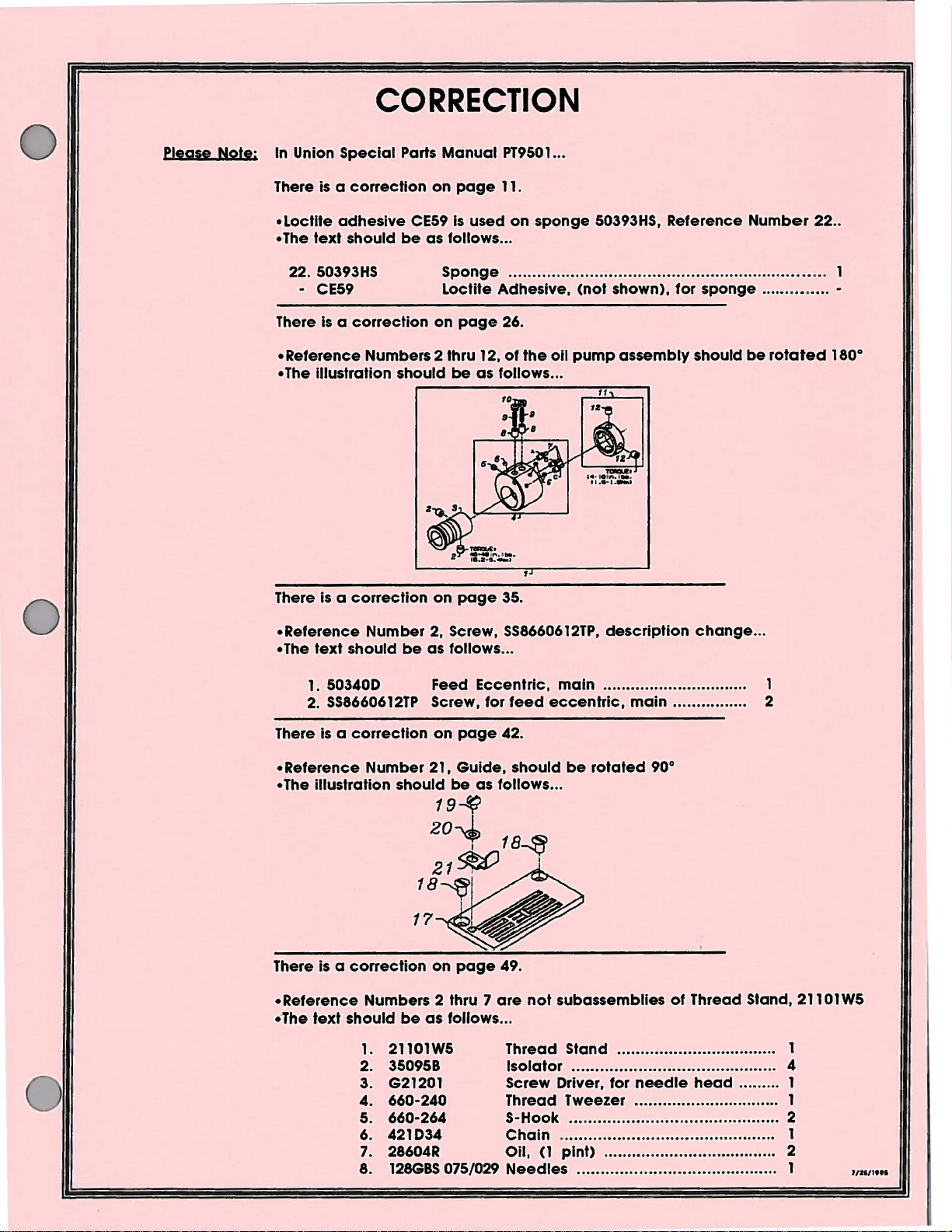
CORRECTION
please Note: In Union
There is a
•Loctite
• The
text
50393HS
22.
- CE59
is a correction
There
• Reference Numbers 2 thru
•
The illustration should
There is a
Special
correction
adhesive
should
correction
Parts
Manual
on
page
CE59
is
used
be
as follows ...
Sponge
Loctite Adhesive,
on
page
12,
be
as follows ...
on
page
PT9501
11.
26.
of
35.
...
on
sponge
.................................................................. 1
the
50393HS, Reference
(not
shown),
oil
pump
assembly
Number
for
sponge .......••..... -
should
be
rotated
22
..
180°
0
•Reference
• The
text
should
1.
503400 Feed Eccentric,
2.
SS8660612TP
There
There is a
•Reference
··
is a correction
The
text
should
Number
correction
Numbers 2 thru 7
1.
2. 350958
3. G21201
4.
5. 660-264 S-Hook ... ..........•.............................. 2
6. 421034
7.
8.
2, Screw,
be
as follows ...
Screw, for
on
on
page
be
as follows ...
21101W5 Thread Stand .................................. 1
660-240 Thread Tweezer ...........•.......... ......... 1
28604R Oil, (1
128GBS
075/029
page
49.
are
SS8660612TP,
main
feed
eccentric,
42.
not
subassemblies
Isolator
Screw Driver, for
Chain
Needles
description
............................... 1
...•.......... ............. ................ 4
............................................. 1
pint)
..................................... 2
. ............. ............................ 1
change
main................
of
Thread Stand, 21101W5
needle
head
...
2
......... 1
7/21/19tl
Page 4
•
PREFACE
•
SAFElY
•IDENTIFICATION
•CLASS
•STYLE
•ILLUSTRA
•IDENTIFYING
•
NEEDLES
•
BUSHINGS
•
NEEDLE
•
UPPER
•SPREADER
•
THREAD
•
TENSION
•PRESSER
•COVERS,
•
LOWER
•LUBRICATION
•
LOOPER
•
NEEDLE
•LOOPER
•
FEED
•
FEED
•COVERS,
•COVERS,
•SEWING
•NEEDLE
•TABLING
•
ACCESSORIES
•NUMERICAL
•NUMERICAL
•NOTES
•NOTES
•NOTES
•NOTES
............................................................................................................................................................... 2
RULES
DESCRIPTION
OF
BAR
MAIN
MAIN
GUARD
DRIVE
DRIVE
DIPPER
................................................................................................................................................................. 52
................................................................................................................................................................. 53
................................................................................................................................................................. 54
................................................................................................................................................................. 55
....................................................................................................................................................... 4
MACHINES
liONS
PARTS
••••••••••••••••••••••••••••••••••••••••••••••••••••••••••••••••••••••••••••••••••••••••••••••••••••••••••••••••••••••••••••••••••••••••••••••••••••••.•••••••••
•••••••••••••••••••••••••••••••••••••••••••••••••••••••••••••••••••••••••••••••••••••••••••••••••••••••••••••••••••••••••••••••••••••••••••••••••••••••••••••
••••••••••••••••••••••••••••••••••••••••••••••••••••••••••••••••••••••••••••••••••••••••••••••••••••••••••••••••••••••••••••••••••••••••••••••••••••••••
SHAFT
........................................................................................................................................................... 15
GUIDE
RELEASE & THREAD
FOOT
UPPER
SHAFT
..................................................................................................................................................... 27
DRIVE
THREAD
MECHANISM
MECHANISM
LOWER
LOWER
PARTS
(EXTRA
.................................................................................................................................................... 49
INDEX
INDEX
CONTENTS
OF
MACHINES
........................................................................................................................................... 5
........................................................................................................................................... 5
•••••••••••••••••••••••••••••••••••••••••••••••••••••••••••••••••••••••••••••••••••••••••••••••••••••••••••••••••••••••••••••••••••••••••••••••••••••
•••••••••••••••••••••••••••••••••••••••••••••••••••••••••••••••••••••••••••••••••••••••••••••••••••••••••••••••••••••••••••••••••••••••••••••
............................................................................................................................................
...................................................................................................................................................
LIFT
.............................................................................................................................................
ARM
........................................................................................................................................ 23
.......................................................................................................................................... 25
................................................................................................................................................... 29
..................................................................................................................................................
TAKE-UP
.................................................................................................................................. 35
.................................................................................................................................. 3 7
BED
......................................................................................................................................... 39
BED
.................................................................................................. ; ......................................
................................................................................................................................................... 43
(EXTRA
SEND
OF
OF
SEND
CHARGE)
PARTS
PARTS
•••••••••••••••••••••••••••••••••••••••••••••••••••••••••••••••••••••••••••••••••••••••••••••••••••••••••••••••••••••••••
TENSION
................................................................................................................................. 33
CHARGE)
........................................................................................................................... 50
...........................................................................................................................
.............................................................................................................
........................................................................................................... 45
..................................................................................................................... 47
5
5
6
6
9
11
13
17
19
21
31
41
51
3
Page 5
t.
Before
starting
operators.
putting
of
each
the
machines
machine
described
Is
only
in this
permitted
SAFETY
manual
after
taking
RULES
Into service,
notice
of
the
carefully
Instructions
read
the instructions. The
and
by
qualified
IMPORTANT!
2.
Observe
3. The
4.
5. Wear safety glasses.
6.
7.
sewing
It has
conformed
changes
The
been
Each
machine
described
the
description,
All
safety
the
machine
In
case
warning
Before
motor
the
national
machines
ascertained
with
the
is
only
in
paragraph
is
not
devices
of
machine
are
must
without
made
hints In the Instructions
putting
supplier.
described
EC
the
conversions
at
the
safety rules
that
the
Council
allowed
"STYLES
as foreseen.
be
In
position
appertaining
your
own
machine
valid
In this instruction
sewing units
Directives (89/392/EEC,
to
be
OF
and
risk.
into service, also
for
your
country.
manual
which
used as foreseen.
MACHINES"
when the
safety
changes
are
marked
of
this Instruction
machine
devices
all
valid
with
read
the
safety rules
are
prohibited
these sewing
Annex
The
foreseen use
Is
ready
Is
prohibited.
safety rules must
one
of
these
machines
II
B).
manual.
for work
two
from
being
of
the
Another
or
In
be
considered.
symbols:
and
Instructions
put
into
will
be
built
particular
use,
operation.
Conversions
from
service
into,
machine
going
beyond
Operation
the
until
have
Is
of
and
8. When
9.
t 0.
11. Work
12. Before
doing
main
switch
t When
8.
8.2 When
dog,
8.3 When
8.4 When
8.5 When using
Maintenance,
special
Any
work
supervision
on
described
disconnected
disconnecting
to
be
removed
the
or
replacing
needle
leaving
doing
skilled
on
of
parts
in
doing
following
by
pulling
threading
any
guard,
the
maintenance
clutch
repair
personnel
the
special
and
the
maintenance
from
from
and
electrical
skilled
equipment
applicable
the
compressed
by
bleeding
the
machine
out
the
needle(s),
parts
folder,
workplace
motors
compressed
without
conversion
under
equipment
personnel
under
sections
and
.
has
to
main
plug:
looper,
such
fabric
and
work.
consideration
repair
air
spreader
as needle(s), presser foot,
guide
when
actuation
work (see
must
.
electrical
of
standard sheet
work
air
supply.
supply (i.e.
be
disconnected
etc.
etc.
the
workplace
lock,
item
8) must
of
the
Instructions.
be
done
power
on
the
pneumatic
In
pneumatic
is
wait
until
by
Is
not
DIN
VDE
case
equipment
from
the
throat
unattended.
the
motor
be
done
an
electrician
permitted.
0105.
equipment,
of
existing
with
power
plate,
is
only
by
or
Permissible
residual
air
supply
looper,
stopped
trained
under
the
machine
air
tank),
by
turning
spreader,
totally.
technicians
direction
exceptions
has
pressure,
the
pressure has
off
feed
to
after
the
or
and
are
be
4
Page 6
IDENTIFICATION OF MACHINES
Each UNION
to
the
number
Precision
enclosed
replaceable
Independently
FS332L01-3B
FS332L01-2C
SPECIAL
middle
plate
high
feed
__
__
machine
of
the
machine
affixed
speed,
filter. Main
driven rear
to
two
and
looper
LAP
Application
Seam Specifications 605 LSa-1. Standard
060, (15/64", 6.0mm).
090/036.
R.P.M.
LAP
Application
Seam
Recommended
recommended
is
Identified
under
the
right
or
three
drive
feed
has thumbscrew
needle
SEAMING. Three
SEAMING.
Specifications
the
rear
needles,
mechanism,
guard.
- For
Maximum
- For
by a style
tension assembly.
base
of
the
machine.
number,
CLASS DESCRIPTION
top
coverstltch, differential
automatic
adjustment
STYLE
crotch
Two
crotch
needle
speed,
OF MACHINES
needle,
Recommended
recommended
needle,
602 LSa-1. Standard
128GBS,
depending
top
seaming
top
seaming
needle
coverstltch,
operations
coverstltch,
operations on
on
which
The
serial
forced
and
differential
gauge
needle
speed,
depending
range
application,
is
stamped
number
feed
feed
tandem
on men's
numbers 056,
128GBS,
tandem
men's
gauge
sizes 065/025 - 090/036.
into
is
stamped
flat
lubrication
feed
has
differential
and
needle
on
application,
differential
and
number
is
up
to
6500
the
style
bed
machines.
system with
lever
boy's
(7
/32", 5.6mm)
range
boy's
040, (5/32", 4.0mm).
R.P.M.
plate
affixed
into
the
serial
Totally
easily
adjustment
feed.
knit
underwear.
sizes
is
up
feed. -Typical
knit
underwear.
and
-Typical
and
065/025-
to
6500
Maximum
This
manual
mechanism
opposite
number
Numbers
Illustration. The
listed in
Component
descriptions
has
been
are
shown so
the
Illustration will
of
pieces
In
the
first
the
second
parts
under
required
column
reference
of
the
5. 503668 Needle
6. 50358V
7.
50370F
8.
SS7060310SP
When a
description.
be
"Ref. No. showing
A
the
part
mentioned
numerical
illustration
Is
common
However, when
In
the
no
index
of
and
description
ILLUSTRATIONS
arranged
column.
sub-assemblies
description
Thread
Needle Thread Strike-Off
Thread Strike-Off Component .......................................................................... 1
Screw, for plate strike-off
to
description
Part No.
all
the
to
simplify
that
the
parts
may
be
found
in
the
are
reference
number
Strike-Off Assembly
all
machines
the
Is
for
parts shown in this
when
a listing
particular
should
which
of
the
covered
parts for
and,
if
location
only a part
necessary,
ordering
be
view
numbers
never
can
main
the
only.
repair
seen in their
of
the parts with their
being
only,
be
be
sub-assembly.
...............................................................................
.....
............................................................................. 1
..................................................................................
In this
various
the
Part
manual
number
parts. Exploded views
actual
shown.
and
merely
used
In
ordering parts.
furnished
manual,
machines
is
is
for
As
no
are
difference
not
for sale
located
is known.
repairs
an
specific
will
at
position
part
numbers,
indicate
are
example
usage
not
the
same,
be
shown in
separately.
the
back.
In
of
various sections
the
machine.
description
the position
Always
indicated
refer
will
the
This
use the
to
be
the
will
On
of
the
part
part
by
indenting
the
following
1
1
mentioned
specific
illustration.
facilitate
usage
of
the
the
page
and
the
In
the
number
their
text.
In
the
will
locating
5
Page 7
IDENTIFYING
PARTS
Where
on
from
PLEASE
For
Each
groove,
diameter
number
Special.
128GBS
When
construction
those
similar
NOTE:
optimum
needle
changing
where
finish
of
represent
construction
ones.
performance
has
and
the
blade
Short,
available
the
permits,
Part
orders
ordered.
each
does
numbers
please
use
part
Is
stamped
not
permit,
represent the
Include
only
part
genuine
with
an
identification
same
part,
number,
Union
Special
Its
name
NEEDLES
both a type
other
measured
the
complete
double
065/025, 070/027, 075/029, 080/032, 090/036.
needle,
and
details.
symbol
groove,
make
size
number.
The
size
between
which
struck
sure
it
is
The
number,
the
shank
is
given
PESCRIPIION
groove,
fully
inserted
type
stamped
and
on
ball
eye,
the
in
part
number.
Jetter
regardless
and
style
replacement
number
the
the
denotes
on
eye.
label
of
spotted,
needle
On
some
Is
stamped
of
which
of
machine
parts.
the
the
needle
Collectively,
all
needles
ball
point,
holder
before
of
in
to
manual
for
kind
of
shank,
the
type
packed
chromium
the
the
smaller
distinguish
they
appear.
which
shank,
denotes
number
and
screw
parts
the
the
part
point,
the
and
sold
by
plated-
is
tightened.
and
part
On
all
was
length,
largest
size
Union
Sizes
When
ensure
needles,
ordering
prompt
type
needles,
and
accurate
128
GBS,
please
size 075/029".
use
processing
the
complete
of
your
type
and
size
numbers
order. A complete
order
as
printed on
should
the
read
as follows: "100
package
to
6
Page 8
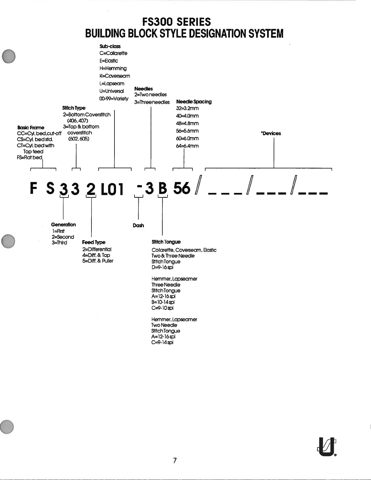
FS300
SERIES
BUILDING
SlilchType
2=Bottom Coverslitch
(406.407)
Basic
Frame
CC=Cyl.
CS=Cyl.
CT=Cyl.
Top
bed.cut-off coverslitch
bed
bed
feed
3=Top
& bottom
std.
with 1
(t:m. tiJS)
~-1
F S 3 3 2
Sub-class
C=Collarette
E=EiasHc
H=Hemming
K=Coverseam
L=Lapseam
U=Unlversal
00-99=Varie1y
LO
1 -3 B
BLOCK
Needles
2=Twoneedles
3=lhreeneedles
STYLE
DESIGNATION
Needle Spacing
32=3.2mm
40=4.crnm
48=4.8mm
56=6.6mm
60=6.crnm
64=6.4mm
J.
56/
__ / _-
SYSTEM
"Devices
_/
__
_
T T
Generation
l=Rrst
2=Second
3=Thlrd
Feed Type
2=Differential
4=Diff. & Top
5=Diff. & Puller
Dash
stitch
Tongue
Collarette. Coverseam.
Two & Three
stitch
D=9-16spi
Hemmer.
Three
stitch Tongue
A=l2-16spl
B=lQ-14spl
C=9-10spi
Hemmer.
Two
stitch
A=l2-16spl
C=9-14spi
Needle
Tongue
Lapseamer
Needle
Lapseamer
Needle
Tongue
ElasHc
7
Page 9
8
Page 10
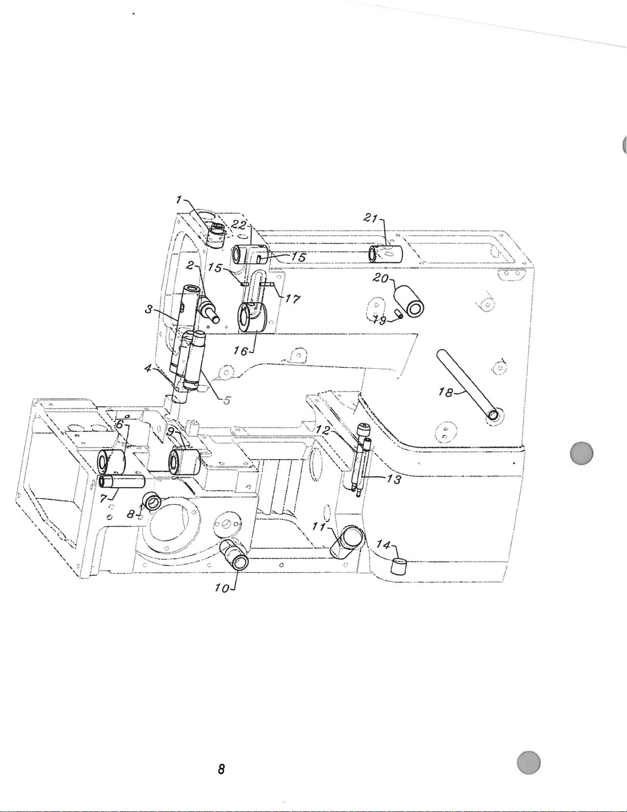
BUSHINGS
Ref.
No.
Part No.
1.
50354J Bushing,
2. 50332U
3.
50347L
4.
50330CZ Bushing,
5.
50354H Bushing,
6.
50344AH
7.
50368AB
8.
50344E Bearing .............. .......................................................................•............ 1
9.
50344AJ Bushing,for
10. 35036AB Bushing,for
11. 50393GE
12. 50393EV Fitting,
13.
50393FU
14.
22571L
SS8090710SP
15.
50393ET
16.
17. 50393FL
18. 50392AB
19.
PS0400142KH
20. 50381E
21. 50347E
22.
50347F
Description
for
needle
Pin, for front
Bushing,
Bushing,for
Bushing,
Oil
Sight
Fitting,
Screw,
Screw .•................................................................................................... 2
Bearing .................................................................................................. 1
Brass Tube,
Bushing,
Pin
..........•....................•.......................................................................... 1
Bushing,
Bushing,for
Bushing,
lifter
for
spreader
for
presser bar............................................................................ 1
for
needle
lower
for
needle
lower
needle
Gauge
filter .................................... ..........................................•.............. 1
oil
tube
for
drain
front
for
tension release ............................ ..... ..... .......................... ... 1
for
lifter lever,
spreader, rear....................................................................... 1
for
spreader, front..................................................................... 1
bar,
upper
lever
................... .......... ....... ... .................................... 1
drive...................................................................... 1
bar,
lower
mainshaft,left
lever
mainshaft, right............................................................ 1
guard
.... ..... .. ... .. ... ..... .. .. . ..•. ... .. ..... .. ... ..... ..
...........•........................................................................... 1
plug....
............................................................................ 1
................................................ ... ....................•.......... ... 1
back
..............................................•............... 1
................................................................ 1
.............................................................. 1
...... ..... ............ ..............
....... ................... ....... ..... .................................. 1
...............................................•................ 1
..
................................ 1
.. . .. ..
... .. ... .. .•..... ...
Amt.
Req.
..
... 1
9
Page 11
---f(
1
2 '
~
r
~:~.
~.:
.;
~
: )
··
..
... , ...
I
3
TORCUE:
18·20in.lbs.
12.0-2.3Nml
11
·,.f!l1o
TORQUE:
32-3'1in.lbs-
13.6·3.9Nml
21
23
U.
4
cY'/
?
:~~~
~:
:.;
(~_
.....
1
..................
76),/
. . 8
10
Union
Loctite:
Spaciol
No. CE27
Page 12
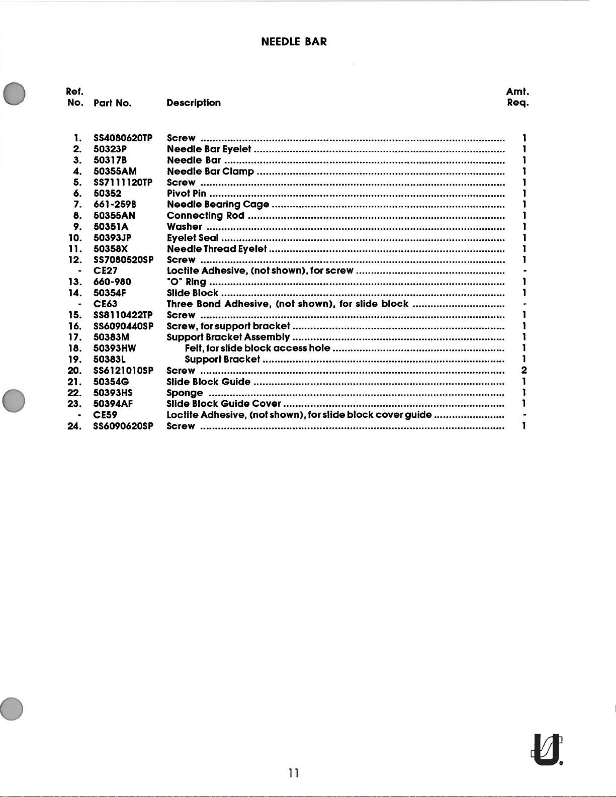
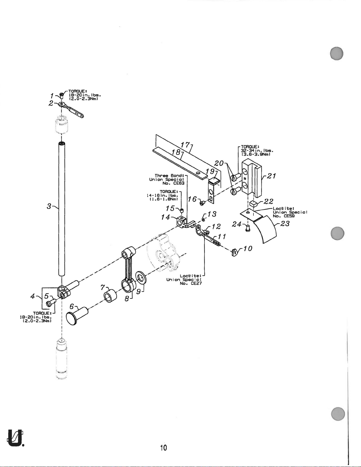
NEEDLE
BAR
Ref.
No. Part No.
SS4080620TP
1.
2. 50323P
3. 50317B
4. 50355AM
SS7111120TP
5.
6. 50352
7. 661-259B
8. 50355AN
9. 50351A
10. 50393JP
11. 50358X
12.
SS7080520SP
- CE27
13. 660-980
14. 50354F
- CE63
15.
SS8110422TP
16. SS6090440SP
17. 50383M
18. 50393HW
19. 50383L
20. SS6121010SP
21. 50354G
22.
50393HS
23. 50394AF
- CE59
24.
SS6090620SP
Amt.
Description
Screw
Needle
Needle
Needle
Screw
Pivot Pin................................................................................................... 1
Needle
Connecting
Washer.................................................................................................... 1
Eyelet
Needle
Screw
Loctite
...................................................................................................... 1
Bar Eyelet .................................................... ................................ 1
Bar . ... .... ... .. ... .. ... .. ....... ... .. .. . .. ... ......... ... .. ... .. .. ... .. ... .. ... .. .. ..... ..... ... 1
Bar
Clamp
...................................................................................................... 1
Bearing
Seal
....... ... ..... .. ..... .. ... .. ... .. .. ... ...... .... ....... .. ... .. .. ... .. ... ..... .. .. ........ ..... 1
Thread
...................................................................................................... 1
Adhesive,
................................................. .................................. 1
Cage
..................................... ....... .................................. 1
Rod ............. ....................................... .................................. 1
Eyelet .... ... .. ..... .. ... .. .. ......
(not
shown), for
screw
..
.. ..... ..... .. .. ... .... ... .. ... .. ....... ........ 1
................................................. .
Req.
·o· Ring ............................... ................................................................... .
Slide Block .............................................................................................. .
Three Bond
Screw
Screw,
Support
Felt, for slide
Support
Screw...................................................................................................... 2
Slide Block
Sponge
Slide Block
Loctlte Adhesive,
Screw
Adhesive,
...................................................................................................... 1
for
support
Bracket
................................................................................................... 1
..................................................................................................... .
Assembly
block
Bracket
Guide
Guide
(not
shown),
bracket....................................................................... 1
........... ..........
access
................... .............................................................. 1
................................................................ .................... 1
Cover
(not
.. .. ... .. .. ... .. . .. .. ..... .. ..... .. ... .. .. ... .. ..... .. . .. .. ............... 1
shown), for
for slide
hole.......................................................... 1
slide
block
block
..
................................................ 1
cover
........ ...................... .
guide
......................
..
ll
Page 13
TORQUE:
46-
48
i n • I
15.2-5.4Nml
bs
•
TORQUE:
54-56in.lbs.
f
16.0-6.3Nml
~-+--
/
~/
\';:ROUE:
54-56
in.
16.0-6.3Nml
lbs.
2
~,~
....
~
.....
--
TORQUE:
46-48
15.2-5.4Nml
~
1
\Q)~
)1
)
)J
"-""'
in. I bs.
~
::.'-
•.
qi,\
Bt·
12
Page 14
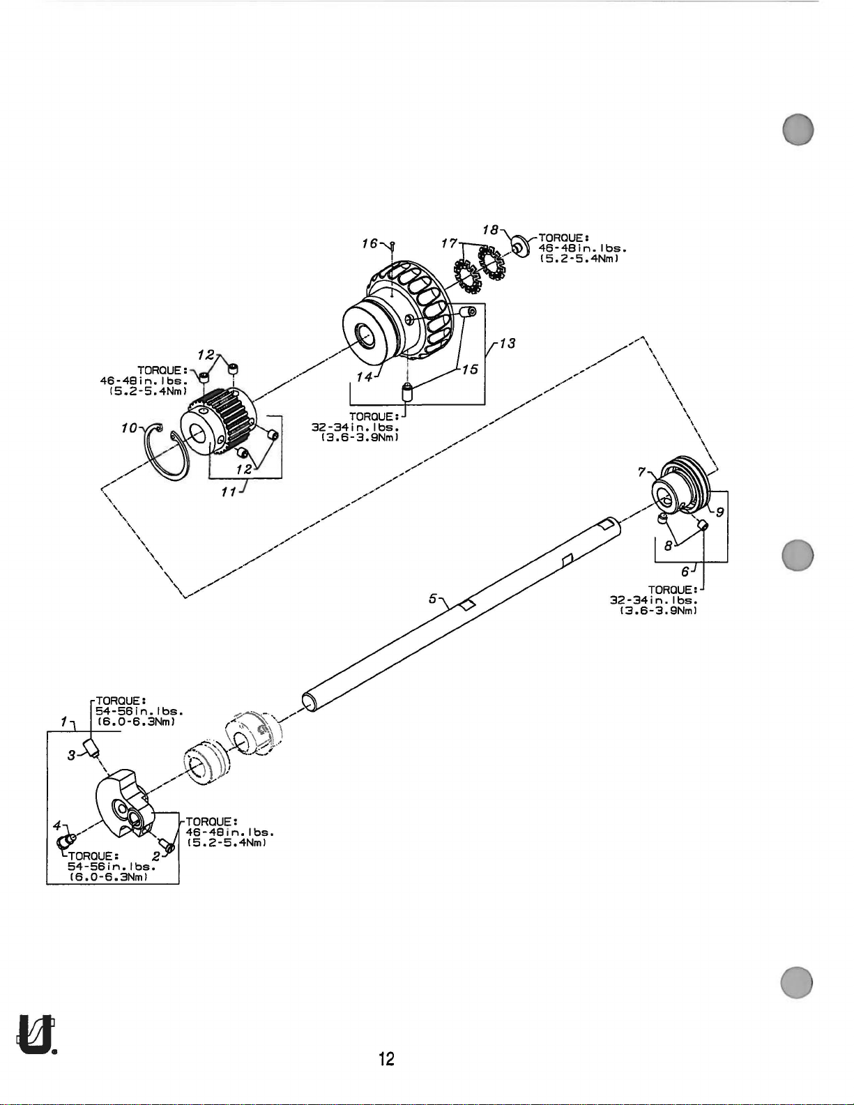
UPPER
MAIN
SHAFT
Ref.
No.
Part No.
1. 50391
2.
SS7111120TP
3.
SS8681412TP
4.
SS7681410TP
5. 50322AF
6.
50335BD
·7.
8.
SS8660612TP
·9.
10. 661-262
11.
50342BE
12.
SS8661012TP
13. 50321F
.14.
SS8681412TP
15.
660-1043
16.
661-261
17.
18.
SS7660520SP
·NOTE:
Not
sold
separately.
Amt.
Description
Counter
Upper
Bearing
Retaining Ring ........................................................................................ 1
Sprocket,
Handwheel
Load Ring, for
Screw,
Weight
Screw,
Screw,
Screw, for
Main
Adapter
Bearing
Screw,
Ball Bearing, for
for
Set Screw,
Ball Bearing . ..... .. ...
Set Screw,
Tack
Pin,
for
hand
..... .. ..
for
counter
for
counter
counter
Shaft ............................... ................... .................................. 1
Adapter
for
upper
for
................................................................... .......................... 1
for
for
lower
wheel
weight
weight................................................................. 1
weight.................................................................. 1
Assembly . ... .. .. ..... .. ...
............................................. .................................. 1
bearing
upper
main
sprocket
handwheel
handwheel
main
preload
..
........ .... .. .... .... .. ..... .. .. .. .... ...... .. .. .. .. .. .. .. .... .... .... ... 1
. ... .. ..
..
...
..
... .. .. ... . . .. ....... ... .... ... .....
..
..
..
. .. .......... .. .. ... .. .. ... .... ..... ..... .. ... 1
adapter......................................................... 2
main
shaft, middle.......................................... 1
shaft .............................................................. 1
.................................................................... 4
..
.. .. ...
..
. ..
..
.....
..
... ..
..
. ..
..
..... .. ...
. .. ....... ...
.......................................................•........... 1
shaft................................................................ 2
......... .. ..... ........... ... ....... .. ....... .. ...
..
... .. .. ..... .. ... .. .. ... .... .....•. ..... ....... ... 2
..
... .. .. ...
..
............ 1
..
. .... ....... .. 1
..
..... .. .. ... 1
Req.
13
Page 15
Fi
bushing
grease,
Special
GAlS,
does
out-
14 -
I
II
not
either
TORQUE:
16
i n • I
1.6-1
.BNml
6
10y
NOTE:
middle
wit-h
Union
No.
so
it
run
end
bs.
7
8--@)
9
~
...
11 ·
.. ! ..
f-
:I:.)
r: 1
~
0 •
00
••
; :
;
:. :.
~ . ...:~
.......
~
~
·
TORQUE:
32-
13.6-3.9Nml
TORQUE:
46-48
i
15.2-5.4Nml
n.
I
34
bs.
i n • I
bs.
22
TORQUE:
32-34in.lbs.
13.6-3.9Nml
TORQUE:
18-20
in. I bs.
12.0-2.3Nml
16
14
Page 16
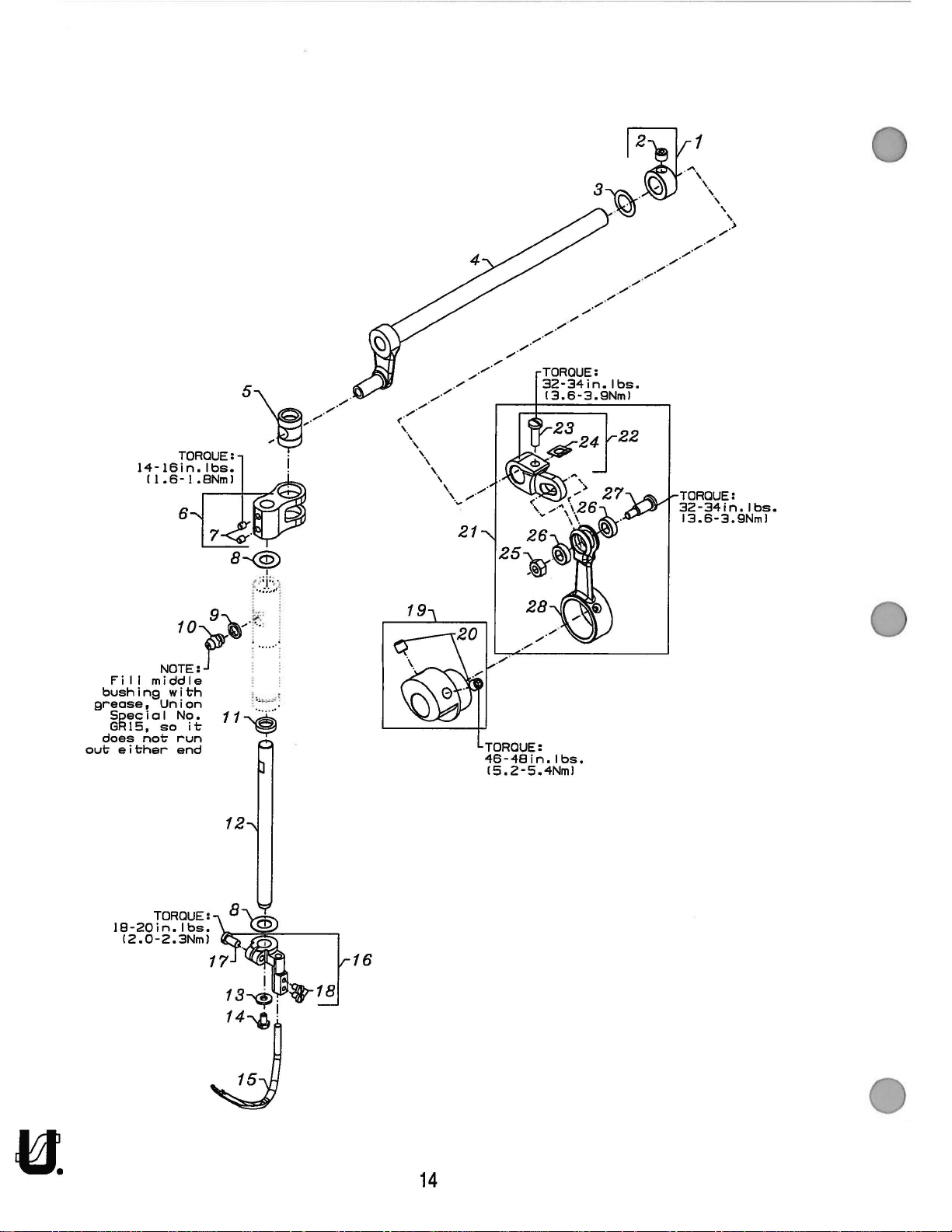
SPREADER
Ref.
No.
Part No.
1. 50335AW
2.
SS8660512TP
3. 961628
4.
503608
5. 50347J
6.
50347C
SS811
7.
8. 61351C
9.
10. 50362
11. 660-739
12. 50347G
13. 53678N
14.
15.
16. 50346A
17.
18.
19. 50360
20.
21. 29126FL
22.
23.
24. 82531704000
25. NS6110530SP
26. 50347K
27.
28. 50360D
- 28604X
- GR15
0422TP
50335AV
SS9090640S
50360E
SS7110910TP
SS7080510TP
SS8660612TP
50360C
SS7121410TP
SD0641103TP
Description Req.
Collar,
Washer ...............................•.................................................................... 1
Crankshaft, for
Pin, for
Lever, for
Washer ................................................................................................... 2
Collar
Lubrication Fitting .. .. .. ... .. ... . ... ... .. .. ... ..... .. .. .. ... ..... ......... ... .. .. .....
Oil
Shaft,
Washer ................................................................................................... 1
Hex Screw,
P
Spreader.................................................................................................. 1
Spreader
Eccentric,
Spreader
Grease
Tube
for
spreader
Set Screw .......................................................................................... 1
spreader
spreader
Set Screw ........................................................................................ 2
..................................................................................................... 1
Seal ................................................................................................. 1
for
spreader,
for
vertical
Holder
Screw .••......•..•..............•......................•......•..................................... 1
Screw ............................................................................................... 2
spreader
Screw ......................................................................•....................••... 2
Crank
Spreader Shaft Driving Arm ............................................................... 1
Screw •............................................................•............................ 1
Bind Washer . .....
Hex Nut,
Collar,
Stud .............•................ ..................................................................... 1
Connecting
Of
for
for
spreader
Gun
(not
Grease, 14oz.
shaft ............................................ •.......................... 1
spreader
rocker........................................................................... 1
vertical
. .. .. . .. ... ... . ..... ..... .. ... ..
Rod Assembly .
spreader
Rod,
shown,
assembly ..............................•.......................... 1
holder
drive
for
shaft ............................................................ 1
.....•. ........ 1
... ... ..... .. ........ ...... .. ... ..
shaft •
..
. .... .. .. .......... .. . . .•. •...... .... ..... .. .....
..
... .. .. .. . .. ... .. .. . .... .. ... . .... ...•..... .......... 1
..
...•................................................................ 1
.. . ..
.. ..... ....... .... ... .... ....... ..... .. ..... .. .•... ..... 1
•....
..
... .. .....
..
... .. ... .. .. ..... ..... .. ... ......... ... .. ... .. .......... 1
drive
driving
spreader
extra
(not
.............................................................. 1
arm
....................................................... 2
drive
... .. ..•.. .. .. ..... ....... .. .. .. ... ..
send
charge)
shown,
extra
send
..
.............. .. ...... .. ........... 1
..
... .... ...
..
............................................. 1
charge).......................... 1
....... ... 1
Amt.
..
... 1
15
Page 17
!.
...
...
· :/<
·:·
··
~~
'
'·,
...
..
······.:
..
..
.•.
..
:::·::
'~
l:
r1,
..
:::
'
.
::
......
.
::·;:··:.;.~:;;,
·
. . .
-~:
::·:
:':-:. ·:
. :.
~
::
r;:!
V\·:
:.-·
....
······
....
-r:
····
. ·.::
40
·.
..
..
···
. .
..
····
··
.. ·:-
...
.... ...
·
··
....
··-
...
: .
-
.. .
··-.
..
·•
';,
_
..
:·
:·
~
,
..
_ ...
····
.:.
· .
..
-···
·-
:.
·.
·=·-.
L:·.
.
....
. .
.
>:.
-~~~\
·-
..
.
~
...
-.
.
.---::
: .
··
····
:
:.
·
..
L
.":
:~:
...
~
-
-··
.
...
..
·
·_.:.>
.:.
·::
.
..
-··
-·
..~···
....
-··
16
Page 18
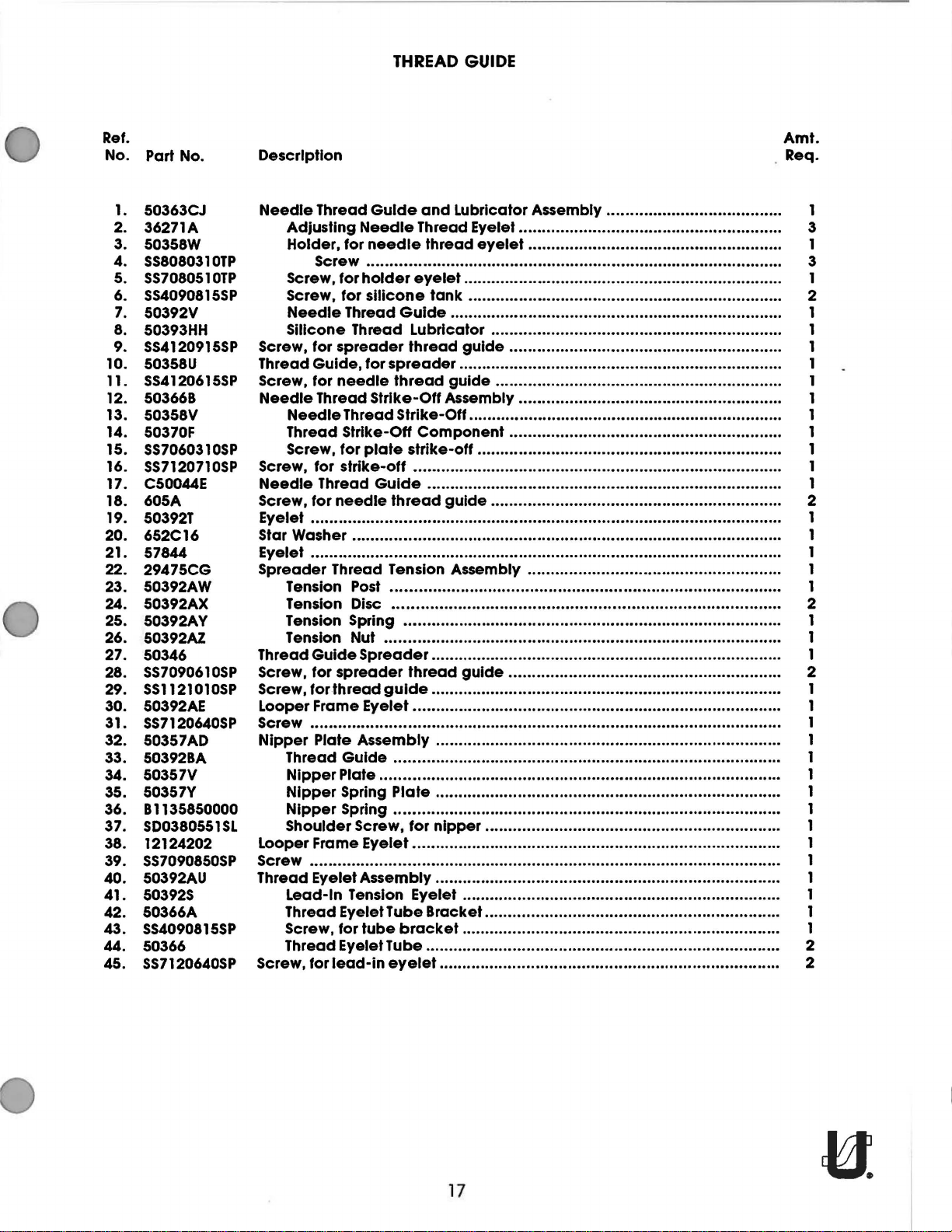
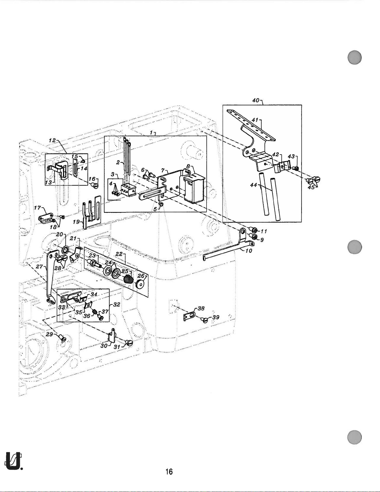
THREAD GUIDE
Ref.
No.
Part No.
1.
50363CJ
2.
36271A
3.
50358W
4.
SS8080310TP
5.
SS7080510TP
6.
SS4090815SP
7.
50392V
8.
50393HH
9.
SS4120915SP
10.
50358U
11.
SS4120615SP
12. 503668
13.
50358V
14.
50370F
15.
SS7060310SP
16.
SS7120710SP
17. C50044E
18. 605A
19.
50392T
20.
652C16
21.
57844
22.
29475CG
23. 50392AW
24. 50392AX
25.
50392AY
26.
50392AZ
27.
50346
SS7090610SP
28.
29.
SS1121010SP
30.
50392AE
31.
SS7120640SP
32.
50357AD
33.
50392BA
34.
50357V
35. 50357Y
81135850000
36.
37.
SD0380551SL
38.
12124202
39.
SS7090850SP
40. 50392AU
41.
50392S
42. 50366A
43.
SS4090815SP
44.
50366
45.
SS7120640SP
Amt.
Description
Needle
Screw, for
Thread
Screw,
Needle
Screw, for
Needle
Screw,
Eyelet
Star Washer .... ..... .. .. ........ .... .•• .•...
Eyelet ..................................••..................•.....................•......................... 1
Spreader
Thread
Screw, for
Screw,
Looper Frame
Screw ...................................•.........•..........•..•...•............•......................... 1
Nipper
Looper Frame Eyelet................................................................................ 1
Screw •.•.... .....•.•...........•..••..•..........................................••..••.........•••
Thread
Screw, for
Thread
Adjusting
Holder, for
Screw .........•............. •......................•................•••••.........••.••.•...... 3
Screw,
Screw,
Needle
Silicone Thread Lubricator ............................................................... 1
Guide,
for
Thread Strike-Off Assembly ......................................................... 1
Needle
Thread
Screw,
Thread
for
•.•••..•.........••....••••......•••........•....•..••.•••.•••••..•.......••..•........•..........•... 1
Tension
Tension Disc
Tension
Tension Nut ... .... ..... .....
Guide
for.thread
Plate
Thread
Nipper
Nipper
Nipper
Shoulder Screw,
Eyelet Assembly . ...•... .....
Lead-In Tension Eyelet ..•..•.••...•.•..•........••..............•••........................ 1
Thread
Screw, for
Thread
Guide
Needle
needle
for
holder
for
silicone
Thread
spreader
for
needle
Thread Strike-Off.................................................................... 1
Strike-Off
for
plate
strike-off . •••.•
needle
Thread Tension Assembly ....................................................... 1
Post .
Spring .................•....•.•• •••............•.............••......................... 1
Spreader
spreader
Eyelet .
Assembly . ..
Guide
Plate ....•.•.•..••......•••............ ...........•...............•...............•.••..•... 1
Spring Plate ....................................... ..........••..............••....•... 1
Spring
Eyelet Tube Bracket................................................................ 1
tube
Eyelet Tube............................................................................. 2
lead-in
and
Lubricator Assembly ...................................... 1
Thread Eyelet......................................................... 3
thread
eyelet..................................................................... 1
Guide
thread
spreader
thread
Component
strike-off
Guide
........
thread
..
. .. ..
..
...•.•...•.........................................................•.•.•........... 2
thread
guide......
..
....... .....
•.
•.•
•.
..
••
.•...........•.••.•................. ................••••........•.•......•..•.•... 1
for
bracket.......
eyelet.......................................................................... 2
eyelet....................................................... 1
tank
••.•••..
.....
..
...
•.
•...•..
•..
.... ... ....••. ••.......... ••••.••
...•••........... .....•......•................•.••....•.•...••.•........ 1
guide
.•.•
guide
.•
...••••
guide
.....
.•
..
........
guide
............................................ .......................... 1
...
..
...
•• ..•
nipper
.... .........
..•............. ..... ........•.•......•• •••
.............................................................. 1
.................................•.........•............... 1
••.......
..
.•...
..
...
••
••..•.•...
.. ..
.•......•....•.......••..............•.....................•.•. 2
•.
...•.
•.•.
••••...
...... ... •.....
.....
..
..•
••
..
.......
..
..•.... .....
.•.... .......••.. ....... .......•• •....•............. .... ... 2
..
.•.
•.
..
••...
..
•.
...
•.
•....
..
..... .....
.......... ............ ... • .
.. ..
...
.............................................................. 1
..
......... ..•...... •.... .. ....•....... ....... 1
..... .•....... ..... ..•
..
....... .........•
...
..
..... .•.......
..••.••
••
•..
•.••.
..
..... ........
••
•.•
.. ..
.••
•.••...
.•
.•... .....
..• .....
.. ..
...
..
...
..
...
.•
.•
•....
..
•••
..
..
•••
•.
... .... ..•...••
..
..
.•.
..
..
.....
..
... .... .....
••
•.•...• ........... ... 1
.. ..
..•.. ..•...... .......•...•.•• 1
•.••.
•.
.. .•..•
.••••
..
••••........... 1
.••
•••.
.•......•.•.•.••.
•.•......
.•.
•.
..
..... ..........
•. . ..
..
..
.......•.•••••••. 1
..
...
.•
..•.. ......... ...
.. ..
..••. ....... ..•
.. ..
.....••. .... ..... ...
•.•.. .... ••........
.. ..
•.
...•.
..
..
••.
•..
.... ...
..
.. .. .. •.. ..
..
..
..••..• ..... ... 1
..... ..•..
..
.....
..
••
..
...
•.
. Req.
••...
..
..... ... 1
.•
... 1
......•
••.
... 1
...•... ... 1
..
...
.•
... 1
•..
..
..
... 1
••••••
•. 1
....•
..
... 1
2
1
17
Page 19

1~T~.;.~,~~·
11.6·1
3
.
i
.....
....
.. _
..
....
..
....
...•
..
.......
~~::
;
··
~
i~:
::l.::!-:-.::: .......
......
··:...
...
..
......
~:::-L::~::.::
. :·:
....
··~
-:·
·~~-·
.
·-
'-
..
·
...
.• ' ,
._
-
..
...
........
......
.....
~'
.. /
.
j~
::
;
~~'::.'
r-:___,~--
....
..
-:...~·"
..
...
.
...
....
.
........
.
6
·
..
::·
.
.......................
.
........
..........
U.
18
Page 20

TENSION
RELEASE
8c
THREAD
TENSION
Ref.
No. Part No.
50392Z
1.
2. SS4120615SP
3. 21657Y
402
4.
5. 22596
6. 50392Y
7. 57892K
8. 56392G
9.
B3120352000
10. B3126012000
11. B3120704000
12. 56392H
13.
B3101804000
- B3103804000
- B3121804000
14. B3112704000
15. 56392L
- 56392M
- 56392R
16. 50392W
17. 50392X
18. 50392AV
SS7090520SP
19.
20. NS6110420SP
21. 57865
22. 660-283A
Description
Tension
Screw, for
Tension
5ThreadTensionAssembly
Release
Release
Base
Spring
Binder
Thread
Tension Post . .. ... .. ....... ..... ..... ..... ..... .. ... ..... .. ..... ... .. ............ ... ..... .. ...
Tension Disc
Tension Disc ... .. ........
Tension Disc Felt................................................................................ 5
Spring
Spring,
Spring,
Spring,
Ferrule,
Knob,
Knob,
Knob,
Tension Disc Separator....................................................................... 1
Tension
Guide,
Screw, for guide................................................................................ 2
Nut.................................................................................................... 5
Lead-In
Retainer
Shaft
Assembly............................................................... 1
tension
Screw
Tension Eyelet....................................................................... 5
Shield ...................... ................. .............................................. 5
needle
spreader
looper
tension
needle
spreader
looper
Bracket
for
Thread
Washer
assembly
Lever Shaft
Screw
... .. ..... .....
Felt . ..... ... .... ... .. ... .. .... .... .....
(red)
(blue) .................................................................... 1
(plain)
spring ....................................................................... 5
(red)
(blue)
(plain)
................................................................................. 1
tension
disc
Guide
. .. ....... ..... ... .... ..... ... .. ..... ..... .. ..... .. ... .. ... .. ... .. .. ... .......... 1
.. ..
..... ..... .. ...
Connection
..................................... ....................................... 1
..
..... ........ .. .. . ....... .. ... ..
....................................................................... 1
..
..... ... ..... .. .. ... .......... .. ...
................. ..................... ..................................... 3
.......................................
...................................... ....................................... 3
................ ... ..................................................... 1
............................... ....... ..................................... 1
separator
.................................... .................................... 5
.. ..
..... ... . . .. ...
.. ... ........ ... ..... ........ ........ ..... ......... 1
..
.. ...
....................................................... 2
..
... .. .. ...... .... .. ... ..... 2
..
... .. ... .. ... .. .. ... .. ... ....... ... 1
..
... .. ....... ... .. ... .. ..... ...
..
... .. . . ... .. ... .. ........ .. ...
..
................................ 1
Amt.
Req.
..
... 5
..
... 5
..
... 1 0
19
Page 21

4
[....·
/.
/
3
.
..,
I
I
I
I
i )
. /
~,.
(
I
I
I
)
211)
.
...,
/.
Union
~T;~t~~eciol
CE49
,
0
15
15~
Loctlte:
Specc~~~
No
•
i
5
14
U.
20
Page 22

PRESSER
FOOT
LIFT
Ref.
No. Part No.
1. 11071602
11071701
2.
3. C50056B
4.
50357AA Spring,
5. 50335AF Presser Bar . .. .. .. . . . . . . . .. . . . . . . . . . . . . . . . . . . . . . . . .
6. 50335AG
7.
SS6110610TP Screw,
8. 50335AH
9. SS8110422TP Set Screw.......................................................................................... 2
10. 660-739
11. 52888B
12. 22562 Screw .............................................................................................. 2
13.
RE0500000KO Retaining Ring,
50381F Lever,
14.
15.
SD0790303SP Screw,
- CE49
16. 50355AR Wire
17. 50381G
18.
SS91
5 1740CP Hex Screw ..............................................................•......................... 1
SS6153040SP Screw,
19.
20. NS6150310SP Hex Nut................................................................................................... 2
21. SS6151920SP Screw,
22.
50332V Stopper,
SS6121010SP Screw,
23.
- CE49
24. 50381
25.
R()D68190100 ·o· Ring ..........................................................................•..................... 1
50381B
26.
Description
Adjusting
Locking
Spring Rod . ... ....... ..... ..... .. ... ......... ........ .. ............ ...
Guide
Presser Bar
Screw,
Nut ................. ...... ...................... ........... .................................. 1
for
Plate,
for
presser
for
guide
Guide
for
spring .•................................................................... 1
..
.. ...•. ... . . ... .. ............... 1
bar
.......•.................................................................. 1
..
.. . . . . . . . . . . . . . . . . . . . .. .. . . . . .. .. .. .. .. .. . . .. . . .
presser
plate
bar
................ .......................... .. ...................... 1
. .
..
. ..
..
... .... ...
. ... .. ... .. .. ... ..... .. ...
..
... .. .....
..
.. ... .... ... .. ... .. .. ... ..•.. .. .. ..... ..... .•...
..
.. ... .. ... .. ..••. .. ... .... ..... .....
Oil Seal ..............................................................................•................... 1
Collar
Loctlte Adhesive,
Lever,
Loctlte Adhesive,
Spring,
Utter
..................................................................................................... 1
for
pin
.... ....•....... ............................................................ 1
for
lifter,
front
.........................................................••..•.............. 1
for
wire
Connector
for
lifter,
for
adjusting
for
adjusting
for
lifter
for
stopper
for
lifter
Lev~r
Assembly ........ ..
connector
(not
...•....... ....... ........................ ......... ..... ......•..............•....... 1
rear
stopper
lever
.............•................................................................... 2
(not
lever
..................................................................... 2
shown),
........... ......................................•...... .......•.............. 1
stopper
shown),
.•.......................................................................... 1
for
screw
.........................••......•...............
.. ....... ... .... ..... .. ..... .. ... .. .. ... .. .. ... ..
... .. ... .. ..
.......................................................................... 1
for
•..
..... .......
..
. ....... .... ... .... ..... .. .. . .. .....
screw
.................................................. .
..
. . ..... ... .. .. ... .......
..
..
...•. ..... ..... 1
..
....... ..... 1
.....•.. .... .•........... 1
Amt.
Req.
..
..
... 2
..
... 1
..
1
21
Page 23

22
Page 24

COVERS,
UPPER
ARM
Ref.
No.
Part No.
SS4121615SP
1.
2.
50393EU
B3530555000
3.
RO
4.
5. 50382FW Top
6.
7.
8.
9.
10.
11.
12.
13.
14.
15.
16.
17.
18. 99682XCA
19.
20. 99682XC1
21.
22.
23.
24.
25. 22758E
26. 50393EW
27.
28.
29.
30. 50382GM
31.
32.
33.
195240100
50382FZ
SS4120915SP
50382GB
50382GC
50317C
SS7120640SP
50393HB Plug,
TA1050504RO
50382FX
50382FY
SS4121215SP
T A
11
00604RO
14077 Nut ................................................................................................... 1
99682XC2
99682XC Protect
22766
95978
50382GA
SS4120915SP
SS4120615SP
SS4120615SP
LA452
50393JV
Description
Screw,
Plug, for
Oil
·o· Ring, for
Quad
Screw,
Puller Drive
Gasket,
Needle
Screw,
Plug,
Head
Quad
Screw,
Plug, for
Needle
Rubber
Cover,
Screw,
Screw,
Thread
Screw,
Label,
Sponge,
for
top
cover
top
cover................................................................................... 1
Sight
Gauge,
oil
Cover
Bracket
Bracket
Counter
Spring Washer ......................................................... ........................ 1
Shoulder Screw . .. ... .. ... .... .. . .. .. ... .. ....... ... .. ..
.............................................................................................. 1
Ring,
for
for
puller
Cover
for
puller
Bar
Guard
for
needle
for
bed
......................................................................................... 2
for
bed
.......................................................................................... 1
Cover
Ring,
direction
.. .. .......... ..... ..... .. ... . . . . ... ..... .. ..... .. ... .. ... .... ... ..... ..... .. ..... ....... ... 1
for
for
head
head
cover
Break Protection Shield Assembly ......... ..... .............................. 1
........................................................................................... 1
............................................................................................. 1
Shield .. ... ..
Sunk
Seal,
for
for
thread
for
thread
for
thread
Cover
for
oil
..... ....... .............. ... .. ... .. .......
thread
protector............................................................................... 1
.. ...
..
.. . .. .. ... .. .. .....
top
.............. ............ ................................................... 1
sight
gauge
top
cover
drive
cover
. .... ... .. .. ... .. .. . .. ..
drive
.. ..
..
bar
guard
head
cover
cover
................................................................................ 1
..
Head
needle
take-up
take-up
cover
take-up
of
rotation
... . ..... .......
...................................................................... 1
. .................................................................. 4
cover
... .. .... . .. ... .. .. ..... .....
..... ......... ... ..
... .. ..... .. ... .. .. ...
Screw ................................................................ 2
....... ... .. ... .................. ... .... .... .... .. .. ... ..
................................................................ 1
.... .. .. ................. .... ... .. .. ....... .......... ....... ....... 2
... ........... .....
lever
............................................................... 1
.................................................................... 1
cover............................................................. 1
cover............................................................. 1
...................................................................... 1
..
...
..
....... ..... ... . .
.. ..
. .. .. ... . . ... .. .. ..... ..... .. .. ... .. .......... 1
..
. ....... ..... ..
..
..
.......... .............. .... ............... ..... ... 4
..
.....
..
... .. ... .. ..... .. .. ... .. ... .. .......... 1
..
... .. .. . .. .. ... .. ... .... ..... ....... ...
..
.... ... .... .............. .................. ..... 1
..
... .. ... ......... ... . . .. ... .. ..... .. ...
..
..
... .. .. .. . . . ... .. .... ... ..... ..... .. ...
..
... .. .. ... ..... ......•.•... 6
. ......... ... .... . .... ..... .. ...
..
... ..
Amt.
Req.
..
... 1
..
... 1
..
... 1
..
... ..... 1
..
... 1
23
Page 25

3~~~,
_,/
_,
46-48"f0ROUE:
ln.lbs
15
•2-5.4Nmi
24
Page 26

LOWER
MAIN
SHAFT
Ref.
No.
Part No.
SS7660520SP
1.
660-1062 Spring Washer ...... .. ... .. ...
2.
50374
3.
50321G
4.
SS8661012TP
5.
·6.
50342AX
7.
SS8660612TP
8.
50342BS
9.
50335AK Retaining Ring,
10.
50322AL
11.
50335BB
12.
50322AG
13.
50333A
14.
SS8660612TP
15.
660-934
16.
50322AJ Lower Main Shaft,
17.
SS8660410SP
18.
·NoTE:
Not
sold
Description
Soulder Screw,
Spacer,
Pulley Assembly .. . .. .. .. .. .... .... .... .... .. ..
Sprocket,
Timing
Ball Bearing, for
Retaining Ring ..... ......................................... ......................................... 1
Lower
Coupling,
011
separately.
for
Set Screw........................................................................................... 2
Ball Bearing,
for
Screw .......................................•..... ............ ...............................•..... 2
Belt ....... .. .. ... ..
Main
for
Screw ................................................................................................ 4
Seal .................................................................................................. 1
Screw
............................................•............•.................................... 2
for
pulley
for
lower
for
lower
Shaft,
lower
lower
main
shaft, right................................................ 1
..
.. ... .. ... .. ..... .. ... .. .. ... .. ... . . .. .......... .. ...
assembly
lower
main
..
.. ...
ball
bearing
main
right
main
left
...................•......................................................... 1
. .. . .... .. . ... .. .. ... .. .. .. .. .. .. . .. ....
..
...... .. ..
main
shaft
.................................................... 1
shaft . .. ..•.. ....... .. ..... ... ....... .....
..
.... ..
..
.. ..... .. .. .. ... .. .. .. . . ... .. ..
............................................................. 1
shaft ......................................................... 1
..
.. ... .. ... .. ..
shafts ......•.................................................. ..... 1
•..
.. ..... .. ..... .. ... .. ... .. ....... .. ..... ....... ... .. ... 1
..
.. .. .. .. ..
..
..
•.
... ..
..
..
.. .. .. ... .. .. . . .... ... 1
.. .... .. .. .. . ... ..
..
.. ..... .. ....... ... .. ... 1
..... .. .. .. .. ... .... .. .. ... 1
.•
Amt.
Req.
... ..
..
. 1
.••. ... 1
25
Page 27

22
To
41y
au
5039~[
"7
lower
o i I
bedmount~
castongl
tube
~~~
fr"octor
0
To
oi
1
retlet"VOir
to
i i
pump
CCI
503931-1'1
44~
43~
26
Page 28

LUBRICATION
Ref.
No. Part No.
1.
50393HN
2.
SS8660612TP
·3.
·4.
·5.
·6.
•7.
8. 34393D
9.
50332S
10. 18-1470
·n.
12.
SS8660612TP
13.
SS4091015SP
14. 50393FR
50384
15.
16. 11843208
17.
50393FV
18.
SS7120710SP
19. 258A
20. 50393FH
21.
SS8120410SP
22. 29476SB
23. 41350X
24. C50094B
25. 50393GT
26. 50393HE
27. 50393FK
28. 50393FW
29. 50393FX
30. 50393GU
31. 50393FV
32. 50393HM
33.
22720B
34. 50393FZ
35. 50393GA
50393FS
36.
3 7. 998-358F
38.
SS4090815SP
39. 50393HR
40. 50393HL
41. 50393HK
42. 50393HJ
43.
SS6151812TP
44. WS0631510KP
45. 22571E
46.
670E2
47. 50393EB
50384A
48.
49.
50393FT
Amt.
Description
Oil Pump Assembly,
Screw ................................................................................................ 2
Oil
Pump Bushing,
Oil
Pump Housing, 2
Screw,
Screw ......................................................................................... 3
Oil
Connector
Plunger ............................................................................................. 2
Spring,
Screw,
Collar,
Screw,
Cover,
·o · Ring,
Oil Filter
Oil
Tube,
Screw,
Nut
........................................................................................................ 1
Oil GuHer ............................................................................•................... 1
Set
Screw
Oil Tubing Assembly .............................................................................. 1
Washer, for
Connector
Oil Tube
Plug Screw . .
Oil Tube,
Oil Tube, for
Oil Tube,
"T"
Connector
Oil Tube,
Collar
Screw,
Oil Tube,
Oil Tube,
Oil Tube Holder......................................................................................... 1
Plastic
Screw,
Plug,
Oil Tube,
Felt .......................................................................................................... 1
Oil Tube,
Screw,
Spring Washer ...
Screw,
Plastic Lock Band . ..... .. ..... .. ...
Oil Pan .................................................................................................... 1
for
for
for
Screw .......................................................................................... 2
for
oil
for
oil filter ................................................................................... 1
for
oil
..
... .. ........ .. ... .. . .... ....... .......... ........ .....
for
supply
for
front
............................................................................................. 1
dual
Dual Feed .... ..... .. ... ..... .. ..... .. .. ... .. ... ..
Cover
upper,
supply
for
supply
for
supply
...................................................................................................... 2
for
dual
for
supply
for
supply
Clip
....
for
oil
tube
for
feed
for
suction (1) ........................................................................... 1
for
suction (2) ................... ........................................................ 1
for
oil
for
oil
2-stage
for
housing ....
plunger
plunger
oil
pump
filter
cover
filter
cover
(1) ........................................................................... 1
upper
feed
.. ....• ..... .. ... .. ... .... .... .. .......
.. ..
.. ... ..... .. .. ... .. ....... .. .. . .. .. .. .
front ................... .......................................................... 1
(2) ............................................................................ 1
(3)
.............................................................................. ........ ..... 1
(4) .......................... ..... ......... ...................... ............... 1
feed
connector............................................................... 2
(5) ............................ ................. ..................... ........ 1
(7) ............... .......... ............
..
... .. ...
.. . ..
holder
chamber
pan
. .. ... ....... ... ....... ..... .. ...
..
.. .. ... .... ..... ... .. . . ... .. ..
drain
plug
. ..... ..... .....
2-stage
stage
....... ............ .............................................. 1
..
... ..... .. .. ... .. ... .. ...
............................................................................ 3
.................. ................................................ .......... 2
..
. .. ..... .. ... .....
........................................................................... 1
...
..
..... ... .. .. ...
... ... . . ... ...... ..... ..•... ... ... .. ... ... ... ..... ... ... ... .. ... ..•...... 1
tube
. ... ......... ..... .. ... ...... ... ............ .... ........ .. ... .. .. . 2
connector............................................................. 8
..
...................................................................... ... 1
.. ............ ..... ....... ... .. ... .. ... .. ..... ... ..
..... ...
..
.....
........................... .............................................. 1
......................................................................... 1
..
... ...
..
.....
..
..... ... .. .. ... ..... .. .. ... .. ... .. .. ... .. ... 1
............................................................... 1
..
.. ..... ... .... ... ..... .. ..... .......... 1
..
...
..
.. ... .. ...
..
...
..
...
..
... .. .. ..... ... .. .....
..
..
... ... ........ .. ..•...
.. ..
.. .
..
..
.. ..... ... .... ........ .. ..... .. ..... .. . 2
..
.. ..... ..... .......... .... ..... ..... .. ... .. .. . 3
..
...
.. ..
... ..... .. ... .. ... ..... ....... ... 1
..
. .•.. ..... ..........
..
...
.. ..
... .. ...
..
... .. ..... ....... ... .. ... .. ... 5
..
.....
..
.. . . ... .. ... .. .....
..
..................................... 1
..
..
... . . ..... .. ... .. .. . .. .. ... 1
.. .
..
.. ... .. ..... .. ..... ... .. ... .. ..... .. ... •.... 6
..
... . . .....
.. ... .. ... . . .. ... .. ...
..
... .. .. ... .. ... .......... 1
..
... .. ... .. .. . 3
.. ..
... .. .. .. . .... .. 1
...
..
... . . ... .. ... .. ... 1
.•
... .. .. ... .. .. . 6
Req.
·o· Ring .................................................................................................. 1
Oil Tube,
for
suction ...................... ......... ... .... ... .......................... ............. 1
·NOTE:
Not
sold
separately.
27
Page 29

13
19
'·,.,
5\
'·--.,~
'·
'·,
......
. ,
'·
................
.
................
' ·,
'·,
.
!bottom
Three
Union
screw
Bond:
Special
No.
only!
CE63
28
·~
I
i
................
................
.,
.........
Page 30

LOOPER DRIVE
Ref.
No. Part No.
1.
50313P
2. 22652B10
3. 22565
50309K
4.
5.
SS7120910SP
- CE63
6. 660-893
7.
50344AM
8. 660-455
9. 50313J
10. SS7120910SP
11.
50314F
12.
50314E
13.
50313M
14. 22653J8
15. 667J33
16. 660-979
17. 50342BJ
18.
SS8660612TP
50342BK
19.
20. SS8660612TP
21. 50342BP
Amt.
Description Req.
Looper Holder ...................... ........................................................... ..... 1
Screw, for
Screw, for
Looper .................................................................................................... 1
Screw,
Three Bond Adhesive,
Oil
Bearing Housing
for
Seal, looper......................................................................................... 1
·o· Ring, for
Looper Rocker Assembly .. . .. .. ... .. ... .. ... .. .....
Screw,
Eccentric Retaining Plate ............... .......................................................... 1
Looper Avoid Adjusting
Looper Drive Assembly .. .. .. ... .. ... .. ... .. .. ... .. ... ..
for retaining plate......................................................................... 2
Screw
Cran'k
looper
looper
bearing
bearing
................................................................................................ 1
Pin
. ..... .. ... ..... .. .. . . . .. .. . .. ... .. ... .. ... . . ... .. ... .. .. ... .. ... .. ........ ....... ..... ... 1
holder..................................................................... 1
holder
housing...................................................................... 3
Assembly, for
.. .. .. ...
(not
shown), for
housing
Eccentric
..
.. ..... ... ..
looper
assembly
.......................................................... 1
..
... .. ............... .. .. ..... ..... .. ..... ... 1
screw
drive........................................... 1
...................................... .
............................................... 1
..
... .. ... .... ..... ..... ...
..
... .. ... .. ....... ... .. ...
..
.. ... .. ... ..... 1
..
.. ... .....
..
... 1
·o· Ring............................................................................................. 2
Sprocket,
Sprocket,
Looper Drive
Screw
Screw
for
looper
............................................................................................... 2
for
looper
................................................................................................ 2
Belt .. .. ... .. ... .. . . . .. .. ... .. ..... ............ ...
driven ........... ............................................................ 1
drive . .. ... .. .. ...
..
... .... ..... .. ... .. ... .... ... .. ..... ....... ... .. ..... .. ... 1
.. ..
... .. ..... .. ... .. ...
..
... .. ... .. ... 1
29
Page 31

TORQUE:
14-
16
! 1 • 6 - 1 • BNm l
in. 1 bs.
4
..............
I
I
r-
14~
I
.. ~ ·.-.
15-A
30
Page 32

NEEDLE
GUARD
Ref.
No.
Part No.
1. 50373DA
SS811
SS811
0422TP
0422TP
2.
3. 50368W
4. 50368T
5.
6. 50368E
7.
50368A
8.
50368V
50354l
9.
SS8110422TP
10.
11. 50325AF
12. 50325AE
SS9090410TP
13.
SS7060310SP
14.
15. 50325AD
Amt.
Description
Needle
Connecting
Pivot
Washer ........................•........................................................................... 2
Pivot
Shaft,
Coupling,
Holder,
Needle
Screw,
Screw, for
Needle
Guard
Screw,
link
Screw ........................................•........................................•.............. 2
Pin
for
Screw ............................................................................................... 2
for
Guard,
for
Guard,
Eccentric . .. .. ... .. ... .. ..•.. .....
for
needle
Rod Assembly,
.. .. ... ....... ........ .. ... .... ... .. ..... ..... ... ..... .. ... .. •. ... .. ..... ... .. ....•...
.•........................................•....................•...................••............. 1
needle
for
needle
needle
rear
front
guard
eccentric
for
needle
guard
rear ............. ..... ................... ............................................ 1
needle
needle
front ............ ...........•............ ............ ................................ 1
......................................•....................••...........•.. 1
guard...................................................................... 1
guard
........................................................................ 1
guard
guard
. .. ..... .....
.. . . .. ...
..
.. ... ..
..•
.. .. ...
..
... .. ..... .. •......... ..... 1
...
..
...
..
.... ... ... ... ...... ... ... ...
guard
.. ... ........ ... ...... ..... ..• ........... ... 1
..
... . ... ........ ....... ..................... ..... 1
..
.. ... .... ... . . ... .. ..
..
...
..
... .. .....
.•.
............. 2
••
•..
..
..
..... .. ... 1
Req.
..... ... 1
31
Page 33

17
1
~8
25
31
32
Page 34

LOOPER
THREAD
TAKE-UP
Ref.
No.
Part No.
1. 50357X
2. 51959D
51959K
3.
4. 51959L
5. 519598
6.
51492
52958D
7.
SS7060310SP Screw .••...•......................•.•.....................•.........•....••.••..........•...•.•.... 3
8.
SS6060440TP
9.
WP0330501
10.
50304H
11.
SS9080410SP
12.
41358
13.
50304L
14.
SS7080520SP
15.
50383E
16.
50357W
17.
SS9111010SP
18.
SS611
061
19.
SS7092110TP
20.
21. 50383F
50304K
22.
WZ0640200KP
23.
SD0630275SP
24.
25. 50323R
22894C
26.
27. 503238
22-348
28.
29. 50377R
50323H
30.
77B
31.
OTP
Description Req.
Cast-Off Plate Assembly
Knurled Nut ......
Tension Spring
Roll
Pin
....................••.••......................•.•........•.....•.....•.........•..•...•.•..• 1
Tension Disc . .. ..
Tension Post .... .. ... . . .. ... .. .. ... ... .. .. ..
Take-up
Screw .••...•.....•.•.....••...........•.....•.....•...•................•.....•..••.•..••..•..••.•..•. 1
SP
Washer.............................................................................................. 1
Strike-Off Wire ... ........•.......•..•...•... ...........•.............. •..•• .......•...•........•. 1
Screw .•.•..••...••.••..••..........•....••....•..•....................•...••••.••....••.••••.••••... 1
Washer
Retaining Finger ...••..........•..........•.•...••.....................••...•••.........•...... 1
Screw •..........•......•...........•...........•.•.•..••.................••.••...•..........•..•... 2
Mounting
Cast-Off Plate
Screw,
Screw,
Screw,
Take-Up
Cast-Off Plate Holder ..... .. ... .. ... .. .. ... .. ...
Washer ................................................................................................... 1
Shoulder Screw,
Take-Up Assembly ................................................................................. 1
Set Screw.......................................................................................... 2
Take-up
Spacer
Disc, for
Screw, for
Eyelet........................................................... ........................ 3
....•............•........••••......................•....•......•..•.•.•..•...•••.•..••••.•.. 1
for
collar
for
cast-off
for
collar
Collar
Hub.............................................................. ........................ 1
Pin
............................................................................................. 2
............................................................................................. 1
take-up
.........•..•...•.••.....•.......•.•.••.•........•....•••••••.......•..•..••.••.• 1
Bracket . .••••..
•••....••......•..•.•........... ..........•...... .....•.••.•••.••.......•...•.••••. 1
bracket
holder
bracket
Bracket .......................................................................... 1
for
cast-off
take-up
•...•...•..•.............................•.. .••.•.....•.•.•.•••...••... 1
....•........•.•••.•............................•.....••.• .••.•..•••..•...••...• 1
..
•. •.
..
.••
• ..•. .. .. ..
•.•••••.•
... .. .. ....... ... .. . .. .. .. ... ..
..................................... ........ .... ...................... 1
.......... .............. .....
plate
... ... .. .. ............ ......
disc
.................................................................... 2
..
.. . ..... ..
.•.
•.
.•
.•.
.•.. •.•..•••..••
.. ..
holder
.. ..
.•
..•.. ..•. ...... .. ..•. ...... .....•.. .•
... .. ...
.. ..
... .. ... .. . . .. . .. ..•
..
.•.••••
•••
..
... ..
..
... .. ... .. .. ....... ...
..
.....
..
... .. .......... .... .......... ..... 1
..... .. ..... ... .. .. ... .. .. .......... ..... ..... 1
.......... .................. ..... .... ..... ..... 1
.. .......... ..... .. ..... .. ............ ........ 2
..
.. ... ..••. ..•.. 1
•••• ••• .••.••••.•••.••••.• 1
Amt.
••.•
.•
..
..... ..... 1
2
33
Page 35

_ .
9
_ .
..,.~
.,
·
.
-·
i
i
i
i
a_ . ..-
•
~------=----'
r~]~l
L-· -
~
I
_.J
TCRXJE;
32·341n.ll>••
13.11•3,11NOII
34
Page 36

FEED
DRIVE MECHANISM
Ref.
No. Part No. Description
1.
50340D Feed Eccentric,
2.
SS8660612TP
3. 18-1432
50334BD Hex Eccentric Stud ................................................................................... 2
4.
5. 50334AX Drive Fork Assembly, right ...................................................................... 1
50336U Link
6.
·1.
·8.
9.
50334BE
·10.
·11.
·12.
•13. Feed Bar, differential......................................................................... 1
50334AW Drive Fork Assembly, left......................................................................... 1
14.
·15.
·16.
7.
50336U Link
1
18.
50340E Feed Eccentric
SS8660612TP
19.
20. Feed Dog,
21. Feed Dog,
22. Screw, for
23.
SS7090530SP
24.
50334Y Oil Shield ............. ............................... ..... ......................................... ........ 1
25.
50334V
50334BH Feed Bar Seal ..................................................... ................................... 1
26.
27.
50335AM
28.
SS7090530SP
50335BA
29.
30. 50334BJ Feed Bar Seal .............................................................................. ............. 1
50335AN
31.
SS7090530SP
32.
33.
50337S
34.
SS811
0422TP
35.
50337L
SS611
36.
37.
38.
39.
40.
41.
42.
43.
44.
45.
46.
47.
48. 50337K Plate, for
49.
50.
51.
52.
·NoTE:
0650TP
50337R
SS8090740SP
SS6091022TP
SD0550271TP
50337M Spring,
50337N Bushing,
R0068190100
50337J Stem, for
50337H Differential Feed Lever.............................................................................. 1
SS4121215SP
50337U Stop ....................................................................................................... 2
SS509061
SS3090530SP
5033
RE0250000KO
7P
Not
OSP
sold
separately.
Screw, for
Screw .................................................................................................... 2
Pin
Fork .................................................................................................. 1
Feed Block,
Feed Bar Assembly.................................................................................. 1
Feed Bar,
Slide Block . ... .. ...
Stroke Block . .. ..... ........ .... ...
Feed Block,
Fork .................................................................................................. 1
Pin
Screw ........... .. . . ... ...... ... .... ...
Screw, for oil shield.................................................................................. 2
011
Scraper,
Guide
Screw, for
Guide
Guide
Screw, for
Collar
Coupling,
Collar,
Screw, for spring .................................................................................. 1
·o·
Screw, for stem ...................................................................................... 1
Screw,
Screw, for stop ........................................................................................ 2
Knob,
"E"
Plate, left,
Plate, right,
Plate, front ..................................................................................... 1
..................................................................................................... 1
Screw ......................... ...................................................................... 2
Screw ..................... .... ...................................................................... 2
for
Screw ................................................................................................. 1
Screw ................................................................................................ 1
for
differential
Ring ................................................................................................ 1
differential
differential
for
for
differentia
Ring .................................................................................................... 1
main
............................................................................... 1
feed
drive
fork screw .
.............................................................................................. 1
right
.............................................................................. 1
main
................................................................................. 1
..
...
..
....... ... ......... ... .......
left
............................................................................... 1
. ... ..... .. .. ...
,'
differential...................................................................... 1
differential
main
feed
dogs
front
guide
guide
for
differential
differential
differential
plate
..
... ....... ............ ... .... ...
(see
page
(see
page
43) ................................................................ 1
(see
page
................................................................................. 1
rear
.............................................................................. 1
plate,
left
rear.............................................................. 4
rear
.......................................................................... 1
plate,
.. ........................ ................................ ......................... 2
right,
feed
feed
lever.............................................................. 1
feed
lever
feed
lever................................................................. 1
feed
lever..
feed
lever............................................................... 1
!feed
lever................................................................ 1
..
.......
..
... ..
..
... .......
..
... .......
..
...
..
.. ...
..
...
..
..
...
..
..
... .....
..
..
.....
.. ..
... .... .....
43) .. .......................................... ............ 1
43).......................................................... 2
rear
........................................................ 4
lever
...................................................... 1
....................................................... ...... 1
.............................................................. 1
..
...
..........
.. ..
...
..
.••..
.. ..
..
..... ..................... 2
..
...
..
... ......... ... ..... 1
..
...
..
...
..
....... ...
..
...
..
..... ...... ....
...
..
.........
..
Amt.
Req.
..
... 1
..
... 1
... ....... 2
35
Page 37

36
Page 38

FEED
DRIVE MECHANISM
Ref.
No.
Part No.
22591A
1.
50334BC
2.
3.
50368AD Washer, for
Description Req.
Screw, for
Eccentric
eccentric
Shaft ...................................................................................... 1
eccentric
shaft
shaft
... .. ...
..
.. ... .. ... .. ....... ..... .. ............... .. ...............
..
..
... .. ..... ..... .. .. . ..
..
.....
..
... ..... .. .. ... .. ..... ....... ... 1
Amt.
..
... 1
4. 50334BB Collar ..................................................................................................... 1
5. SS8110422TP
6. 50337T
SS811
7.
8.
9.
10.
11.
12.
13.
14.
15.
16.
17.
18. 50335E
19.
20.
21.
22.
23.
24.
25.
26.
27.
28.
0422TP
661-96 Spring
660-969
SS8661 0
35036F
660-220
35036AZ Brake Pad................................................................................................ 2
50379S Stitch Adjusting Shaft Assembly .. .. ... .. .. ... .. .. .. . .. ... .... .....
503350
22894P
660-980 ·o· Ring,
660-206 Washer, for stitch
35036AP Stitch Knob, Indicator............................................................................... 1
22764A
50335 Spring
22714C Screw, for spring
50355 Spring ...................................................................................................... 1
50335A Spring Holder . .. .. ..... ... .. ... .... ... ....... ... .. .. ... .. . .. .. ...
50336S Stitch Control Lever ............... .... .. .. .. ... . . .. .. ... .. ...
661-35
22596H
12TP
Screw
Collar, for
Screw
................................................................................................ 2
eccentric
................................................................................................ 2
Washer
shaft......................................................................... 1
..... ..... .. ... .. ..... .. ........ .. .. ... .. ... .. .. ..... ..... ..... .. ... .. ....... ..... ...
..
... 1
·o· Ring, for bushing................................................................................. 1
Screw ...................................................................................................... 2
Bushing, for stitch
·o· Ring, for
Collar ...................................................................................................... 2
Screw
Shaft, for stitch
Screw
Pin
Screw
stitch
................................................................................................ 4
stitch
................................................................................................ 1
Retainer . ..
..................................................................................................... 1
................................................................................................ 2
adjusting
adjusting
control
control
control
.............. ... .. . ....... ......... ... .. .. ... .. ...
retainer
shaft
........... ................................................ 2
shaft.............................................................. 1
..
............... .... ..... ... 2
shaft.................................................................... 1
........................................................................... 1
shaft................................................................. 1
..
... ......... ... .. ..... .. ... .. ... 1
........................................................................ 1
..
..
..... ... ..... .. ..... .. ..... ...
..
..
..
.... .. .... .. ...... ............ 1
..
... 1
37
Page 39

Thl"'ee Bondz
Union S
No. CE63
I
top
4
SCI"'eWS
pecial
bot:t:om
onlyl
2
. -:
·I
• .. ···-.. .
; : -:· ·.
. . . .
: . :- .'
. . .
: .
:·
·. .
...
:
~
·:
: . . ·. ·:·.'
.··-
·-.::
::.::. _
_.
...
. .
: ..
,:·
•'
~.
:<=:i.
.
::.
:·:
·
,<
···-
.. .
...
:.::.
. . .
\
0:
. : ...
: . ·
:.
. •,_
··
···-
..
: .
...
-
...
· .
..
.
..
-···
:
·-.:·
..
.
..
..
. . .· ·:
...
·.
·.-
..
··
··
..
-····
::
38
tJ.
: .. . •,
·-
...
·
·
.. _ ..
· ·
·
.
• • 0 • •
.·
..
'· .. ·
.
•.
-
-~-
..
..
~
.. ·
·-r.
..
..:
il
:,.• .-
··
..
· ..
..
:
..
..
.
·.·:
..
.
•:
~
~
•
..
·.
,
...
.
:
::
. .
:,.
•·
.
. .
·. .
..
. .
·-···
• • I • o ·,
....
. : :-. :
··
• •
.
Page 40

COVERS,
LOWER
BED
Ref.
No.
Part No.
1. 18-1448
2. 50301BH
3.
50301BF
4.
50303B
5.
SS6121212TP
6. 50382CP
7.
50382CS
8. C067D
9.
50382CR
10. 50382CL
SS4120615SP
11.
-
CE63
12. 22517
13.
50380KA
14. 50336W
15. 50328
16. 660-939
17.
SS7150740SP
Amt.
Description Req.
Screw .....................................................................................................
left
Cloth Plate,
Cloth
Plate,
Acoustic
Screw,
Cover,
Gasket
Cork
Gasket
Cover,
Screw,
Three Bond
Screw, for
Throat Plate Support,
Screw .......................................................•..........................................•... 2
swing
for
•................................................................................................... 1
........................................................................................................ 2
.................................................................................................... 1
for
for
Dowel Pin........................................................................................... 2
Diamond
Rubber Bumper,
....................................................................................... 1
right
................•..... ..................•............................................ 1
Pad .. ..... ... .. .. ..... ... .. ..... .. ... .. ... .. .. ... ....... ..... .. ... .. ... .. ....... ... ..... 1
plate
feed
feed
cover
Adhesive,
bed
Pin
. .. .. .. . . ..
chamber
chamber,
. .. .
..
. .. ... ..... .. .. ... .. ..... .. ... .. ... .. .. ... .. ... .. ....... ... ....... .. ...
complete
. .. ...•. ... .. ....... ... .. ... .. ..... .. ... .. .. ... .. ... .. ...
for
..
... .. .. ...... .. .. . . . . .. .. .. .... .. .. .. .. .... .... .. .. ...... .. .. ..... 6
. .. .. ... ..
..
... .. ... .... ... ..... ....... ......... ... .. .. ...
rear................................................................ 1
.. . .. .. . .. .. .. . . ....... .. . .. .. . . . . .....
(not
shown),
throat
plate
for
screw
.............................................................. 1
support
..
... .. .. . ........ .. .. . .... ... .. ...
..................................... .
..
.. ... .. ...
........................................... 1
..
.. ... ..... 1
..
..... .. ..... ... 2
..
.. ........ ..... 1
11
..
4
39
Page 41

40
Page 42

COVERS,
Ref. Amt.
No.
Part No.
1. 50393HB Plug ....................................................................................................... 2
50382CM
2.
3. 50382CH
4. SS4151415SP Screw..................................................................................................... 4
5. 50393HA Plug ........................................................................................................ 1
6.
W03
22841U
7.
8. 50383G
9. 50382CG
10. SS7090850SP
50378S
11.
SS9110543CP Screw..................................................................................................... 4
12.
660-1020
13.
SS6120930TP
14.
20
15.
16. 50382T
17. 50393W
18. 22519J
50382CK
19.
22729D
20.
50363CH
21.
50382GT
22.
23. SS4121015SP
50393HU
24.
50382CJ
25.
26. 50332A
39250J
27.
28. 22513D
35569J
29.
50332B
30.
SS7120710SP
31.
22799AH
32.
Description Req.
Quad
Left
011
Machine
Gasket
Dry
Screw
Hinge ..................................................................................................... 2
Rubber
Screw
Washer................................................................................................... 2
Stop, for front
Rubber Bumper ..... .. .. ... ..... .. ........ .. ...
Screw..................................................................................................... 2
Swing Down
Screw..................................................................................................... 2
Lever ...................................................................................................... 1
Handle
Screw..................................................................................................... 4
Plug ....................................................................................................... 1
Cover,
Latch Spring ........................................................................................... 2
Nut •...................................................................................................... 2
Screw..................................................................................................... 2
Nut ......................................................................................................... 1
Support
Screw..................................................................................................... 2
Spring Latch Stud ........... ......... ................................................................ 2
Ring.............................................................................................. 1
End
Cover
Wick.................................................................................................. 1
Support Stud ............................................................................. 4
.................................................................................................. 1
Chamber
.................................................................................................... 8
Bumper .....
.................................................................................................... 4
Cap
for drive belt . . .. ... .. ...
Block ... .... ... .. ... .. ... .. ... ..... .. .. ... .. ...
. ..... .. ... .. ..... .. ... ..... .. ...
Cover
..
cover
Cover
............................................................. ....... ............. 1
........................................................................................... 1
LOWER
... ... .. .. ..... ...
.. ... .. ..... ... ..... .. ... .... ...
................................................................................ 2
..
BED
..
.....
..
.....
..
. .. ..... ...
..
... ..
..
... .. ..... ... .. .. ... . ... . ..... .. ....... ... .. ..... ... 1
..
..... ........ ..... .... ... .. ..... ... ..... .. ... 2
.. ..
...
..
.....
..
... ..... ...
...
.. ..
... .. ..... .. ..... ... .. ... .. .. ... ....... ... .... ... .. ... ..... 1
.. ..
. .... ........ .. ... .. ... .. ... ..... .. ..... ... 1
..
.. ..... ............. ..... 1
..
.. ... .. ..... ... ..... ..... 2
41
Page 43

1
J4-16in.
I l
.6-l.SNml
TORQUE:
lbs.
23
6
6...4
1
7...4
~
i
I
.,l-.
"'?'
42
Page 44

SEWING
PARTS
Ref.
Part No.
No.
1. 50318Y60
50318AA56
1 A.
50318Z40
2.
SS8080310TP
3. 50318AE56
4.
SS6060440TP
5. 50392G
6.
50320T60
6A. 50320AT
7.
G65-134
8.
91
9. 79633
10. 605
11. 22716A
12. 50397A16
12A. 50397G
13. G50-266
14. 57830A
15.
50330Bl16
16. 6-25-55
17.
50324BR60
- 50324BR56
17
A. 50324BJ40
18. 87
19. 22561
20. 27-435BLK
21. 23195
22. 50326AE
23.
50305AN
24.
SS7091110TP
Amt.
Description
Needle
Needle
Needle
Needle
Presser Foot,
Presser Foot,
Throat
Throat
Throat
Screw,
Screw, for
Washer,
Guide
Differential Feed Dog ............ ..... ....... ................... ... ....... ........................ 1
Main
Screw,
Head,
Head, for Style FS332L01-3B
Head,
Screw ......................................................................................... 3
Eyelet ............................................................................................... 1
Screw ............................................................................................... 1
Shank ............................................................................................... 1
Screw .............................................................................................. 1
Spring ............................................................................................. 1
Screw .............................................................................................. 1
Screw ............................................................................................... 1
Stitch Tongue,
Stitch Tongue,
Bushing ........................................................................................... 2
Yielding
Presser Foot Bottom ..... .. ..... ................ ...................... ................... ... 1
Drill Rod............................................................................................ 3
Plate,
Plate,
Plate,
for
..................................................................................................... 1
Feed Dog ...................... ............ .............. ....................................... 1
for
for StyleFS332L01-3B
forStyleFS332L01-2C
Thread Eyelet ....... ..... ..... ............................................................ 1
for
Style
FS332L01-3B
for
Style FS332L01-2C
for
StyleFS332L01-3B __
for
StyleFS332L01-2C
Section . ... .. ... .. .. ... .. .. . .... ... ....
for
StyleFS332L01-3B
for
Style FS332L01-3B
for
Style FS332L01-2C
throat
for
plate
............. ..... .. .. ....... ..... .............. ....... ... .. .. ....... ...
guide
.. .. ....... ............ ... .......
screw.................................................................................... 1
feed
dogs
..
.............. ... .. ............ .....
__
•.
060 gauge................................... 1
__
..
056 gauge.................................. 1
__
..
040gauge
__
..
056
and
__
..
040 gauge................................... 1
..
056
__
•. 040 gauge............................ 1
..
... .. .. . .. .......... .... ... .. ....... ...
__
•.
060gauge
__
•.
056 gauge.................................... 1
__
..
040 gauge................................... 1
..
....... ...
.................................. 1
.060 gauge....................... 1
and
.060 gauge............... 1
.................................... 1
..
....... ...
..
... .... ... ....... ....... ... 1
..
............ ....... ............ ... .. ... 2
Req.
or
..
... 2
..
... 2
4
43
Page 45

1
2~
.,
.
...............
U.
44
Page 46

NEEDLE
DIPPER
(EXTRA
SEND
CHARGE)
Ref.
No.
Part No.
1.
29476RZ
PS0160042KH
2.
3. 50393JD
4.
50393GS Wire, for
CQ202000000 Oil Wick, for
5.
6. 50393GK Felt, for
7. 50393JC
8. SS4090615SP
9. 50393GP
10. 50393GG
WP0531
11.
SS4120615SP
12.
OOOSD
Description Req.
Needle
Roll
Needle
Needle
Screw, for
Silicone
Plug .................................................................................................. 1
Washer.............................................................................................. 1
Screw, for
Amt.
Dipper Assembly ............ ....... ....... .............................................. 1
Pin
.............................................................................................. 2
Dipper
needle
needle
Dipper . .. ... .. ... .. .. ... ..... .. .. ... .. ... .. .. ...
Oil Tank Holder...................................................................... 1
Cover
needle
dipper........................................................................ 1
needle
needle
... .. .. ...
..
.. ... .. ... .. .. .....
dipper....................................................................... 1
dipper
dipper
dipper
............................ .................................... 1
. .. ....... .. ..... .. ... ......... ....... ....... ... ....... .. .....
holder
...... .. ..... .. .. ... .... .. ... .. .. ... .. ..... .............. 1
..
... .. .....
..
..... ..... ....... .. ... ....... .. ...
..
... .... ............... .. ... 1
..
... 1
..
... 2
•
45
Page 47

10
1
I
L-~-------n
t:fV}
14)
46
Page 48

TABLING (EXTRA
SEND
CHARGE)
Ref.
No.
Part No.
1. 21371AAE48
2.
3.
4.
5.
6.
7.
8.
9.
10.
11.
12.
13.
14.
15.
16.
17.
18.
19.
20.
Description
Table
Board
Insert
Nut
Washer
Plastic Tube .................................................................................. .
Threaded
Insert ................................................................................................ .
Keeper
Latch
Bolt ................................................................................................. .
Washer ............................................................................................. 5
Screw ..............................................................................................
Washer ..............•...................................................................•..........
Hex
Screw ................................................................................................ 4
Stop .................................................................................................. 3
Sems
Washer
Plastic Bolt
Bolt ................................................................................................... 3
...........................•.................................................................
............................................................................................. .
...............................................................................................
...........................•............•.................................................
Rod ............................................................................... .
Plate ...................•.................................................................
............................................................................................. .
Bolt
........................................................................................... 4
Nut
.........................................................................................
............................................................................................. 8
Cap
. .. .. .. .. .. .. •.... ...
.. .. ..
.. .. .
..
.. ... . . ... . .
..
.. .. .... . . .. .... ...• .. ........ 4
Amt.
Req.
.
1
1
1
1
1
1
1
1
1
4
2
11
15
47
Page 49

P371-95
'''"'~"'
~
~
8
u.
48
Page 50

ACCESSORIES
Ref.
No. Part No.
1. 21101W5
2. 350958
3. G21201
4.
660-240 Thread Tweezer.................................................................................. 1
5. 660-264 S-Hook .............................................................................................. 2
421
6.
7. 28604R
8.
D34
128GBS
075/029
Description
Thread
Needles,
Stand ........................................................................................ 1
Isolator
Screw
Chain
Oil,
(1
(package
.... .. . .. . . .. . .. .... . ... .. . . .. .
Driver,
.................................................... ....... ..... ................................ 1
pint)
for
needle
........................................................................................ 2
of
1 0) .............. .......................................................... 1
..
. . .. . . . . . .. . ...
head............................................................ 1
..
. . .. . .. .. . .. .. . . ...
..
.... . .. . .... .. . .. . .. 4
Amt.
Req.
49
Page 51

NUMERICAL INDEX OF
PARTS
Part No.
11071602
11071701
11843208
12124202
pqge
.....
21
.....
21
,,.27
.. ,.17
128GBS075/029 .49
14077 1111123
18-1432
1111135
18-1448 1111139
18-1470
20
21101W5
21371AAE48
21657Y ...
22-348
225130
22517
22519J
22561
22562
22565
22571E
22571L
22591A .....
22596 .....
22596H
......
.....
....
.....
..
..
...
..
..... 41
.....
...
..
. .
...
.....
...
..
...
..
.....
.....
27
41
49
47
19
33
39
41
43
21
29
27
9
37
19
37
22652810 ..... 29
22653J8 ..... 29
22714C
22716A
227208 ...
227290
22758E .....
22764A .....
22766
22799AH
22841U
...
...
...
..
...
.. ... 41
.....
..
~~
..
..
37
43
27
41
23
37
23
41
22894C ..... 33
22894P
23195
258A
27-4358LK
28604R
28604X
29126FL .....
29475CG
29476RZ .....
294
343930
35036A8
35036AP
35036AZ
35036F
350958
35569J ...
36271A
39250J " ...
402
41350X
41358
421034
503018F .....
503018H
..... 37
...
. .
...
..
...
.....
.....
.....
7658
.....
...
..
...
.....
....
...
..
...
..
..
...
..
......... 19
. . .
..
...
. .
..... 49
...
..
43
27
43
49
15
15
17
45
27
27
..
37
. 37
37
49
41
17
41
27
33
39
39
9
No.
part
503038 .....
50304 H .....
50304
50304L
50305AN
50309K
50313J
50313M
50313P
50314E
50314F
503178
50317C
503 18AA56 ... 43
50318AE56 ... 43
503
18Z40
50320AT
50320T60
503218Y60
50321F
50321G
50322AF
50322AG
50322AJ
50322AL
503238
50323H ..... 33
50323P .....
50323R
503248J40
503248R56
503248R60
50325AO
50325AE
50325AF
50326AE
50328
503308L16
50330CZ .....
50332A
503328
503325 ...
50332U
50332V
50333A ..... 25
50334AW
50334AX
5033488
503348C
5033480
503348E
503348H
503348J .....
50334V .....
50334Y
50335 .....
50335A
50335AF
50335AG
50335AH
50335AK
50335AM
No.
K I
pgge
39
33
••••
33
...
..
33
..... 43
.....
29
111!129
...
~~
29
.....
29
...
..
29
.....
29
..... 11
..... 23
. I
.43
11.43
.
~~43
... 43
..
11.
13
..... 25
...
..
..... 25
....
. 25
.....
25
...
..
33
...
..
33
... 43
... 43
... 43
.....
31
II •••
31
...
~~
~~
... 43
01111
39
... 43
...
.. 41
.....
41
..
27
...
119
..... 21
....
. 35
.....
....
. 37
..... 37
...
..
35
.....
35
..... 35
35
35
. I I
••
35
37
...
..
3 7
.. 11.
21
.....
... ..
21
.....
25
..... 35
No.
13
11
31
9
35
21
part
No.
pgge
50335AN
50335AV
50335AW
503358A .....
5033588 ...
5033580
503350 .....
50335E
503365
.
II
..
..
~~.15
.... . 15
..
0 •
II
I 13
..
~~
.37
.....
35
35
25
37
37
50336U ..... 35
50336W ... 1139
50337H .....
50337J
50337K
35
0!11135
11 11
.35
50337L ... 1135
50337M
50337N ...
50337P
50337R
...
1135
..
35
. . 11.35
.....
35
503375 1111135
50337T
50337U
.....
. .
...
37
35
503400 1111135
50340E
50342AX .....
503428E
503428J .....
503428K
503428P
...
.....
..
I
....
~~35
25
13
29
~~
.29
29
503428S ..... 25
50344A
50344AJ ...
50344AM
50344E
50346
50346A ...
H
. .
...
...
...
II
..
. 9
..
..
29
. . 9
17
..
15
50347C ..... 15
50347E
50347F
50347G
50347J ... . .
50347K
50347L
50351A
50352
50354F
50354G
..
. .... 9
II ...
11 ...
. .
...
.....
.....
....
11
...
...
15
15
15
11
11
. 11
11
50354H .....
50354J
50354L
50355
50355AM
50355AN
50355AR
50357AA ....
50357AD .....
.....
.....
. .
...
.~~
...
...
31
37
..
11
..
11
.. 21
. 21
17
50357V ..... 17
50357W ... ..
50357X
50357Y .... .
50358U ...
11 ...
. .
33
33
17
17
50358V ..... 17
No.
9
9
9
9
9
Part
No.
pqge
50358W ...
50358X
50360
503608
50360C
503600
..
17
.11
..
11
..... 15
III
II
15
. . . . .
15
.....
15
50360E ..... 15
50362 ...
50363CH
50363CJ .....
50366
50366A
503668 .....
50368A
50368A8
50368AO
50368E
50368T ... ..
50368V ....
50368W .....
50370F
503730A .....
50374
50377R
..
...
.. 41
.....
. . .
II
..... 31
.....
.....
. .
...
. 31
.....
.....
-
~~
..
15
17
17
17
17
37
31
31
31
17
31
25
33
50378S ..... 41
50379S
50380KA .....
50381
503818
50381E ...
50381F .....
50381G ...
50382CG
50382CH .....
50382CJ ....
50382CK .....
50382CL
50382CM
50382CP
50382CR
50382C5
50382FW .....
50382
50382FY
50382FZ
50382GA .....
50382G8
50382GC
50382GM
50382GT
50382T ...
.....
..... 21
. .
...
I
....
..
.....
..... 39
..... 39
.....
FX
.....
.....
...
..... 23
I
••••
.
...
II
. .
11.
..
..
..
37
39
21
..
21
21
41
41
. 41
41
39
41
39
23
23
23
23
23
23
..
23
41
41
50383E ..... 33
50383F .....
50383G
50383L
50383M .....
50384
50384A
50391
50392A8
50392AE .....
50392AU
33
II
...
41
.....
11
11
..... 27
1111
.21
.. ... 13
..
11.
17
.....
17
No.
Pqrt No.
50392AV
50392AW
50392AX
50392A
50392AZ ...
503928A .....
50392G
50392S
50392T
50392V
50392W
50392X
50392Y
50392Z
50393E8
9
50393ET ....
50393EU ..... 23
50393EW
50393EV
50393FH .....
50393FK ...
50393FL ....
50393FR
50393FS .....
50393FT .....
50393FU
50393FV .....
50393FW
50393FX ..... 27
50393FV ..... 27
9
50393FZ ..... 27
50393GA
50393GE ...
50393GG
50393GK
50393GP
50393GS
50393GT
50393GU
50393HA
50393H8
50393HE ...
50393HH
50393HJ
50393HK .....
50393
50393HM .....
50393HN .....
50393HR ..... 27
50393HS
50393HU
50393HW ...
50393JC ...
50393JO .....
50393JP ..... 11
50393JV ..... 23
50393W .....
50394AF ..... 11
50397 A 16
50397G ... . .
9
51492
519598 1111133
v
HL
pqge
...
..
.....
"
II
"II.
..
II •••
1111.
...
II
.. 11.
II
...
·
~~~~
II •••
II
•••
.....
.
II
..
..
~~27
...
..
...
.....
...
.....
...
..
...
..
...
..
...
..
.....
....
.23,
..
....
..... 27
... . .
.. . ..
...
.. 41
..
.....
. . . . .
No.
19
17
. 17
1 7
17
17
43
11
1 7
11
19
19
19
19
27
. 9
23
~~.9
27
. 9
27
27
27
..
9
27
27
..
27
..
9
45
45
45
45
27
27
. 41
41
27
. 17
27
27
27
27
11
..
11
45
45
41
43
43
33
50
Page 52

part
No
.
pqge
No. Part No.
NUMERICAL INDEX OF
part
pqge
No
.
No
.
PARTS
pqge
No.
519590 ..... 33
51959K
51959L
528888 .....
529580
53678N
56392G
56392H .....
56392L
56392M
56392R
57830A
57844
57865
57892K
6605
605A .....
61351C .....
652C16
660-1020
660-1043
660-1 062
660-206
660-220
660-240
660-264
660-283A
660-455
660-739
660-893
660-934
660-939
660-969
660-979
660-980
661-2598
661-261
661-262
661-35
661-96 ...
667J33
670E2
778 ........
79633
87
91 .....
95978
961628 .....
99682XC
99682XC 1 ..
99682XC2
99682XCA
998-358F
8 1135850000
62531704000
83101804000
83103804000
83112704000 ...
83120352000 ...
83120704000
8312180400)
•
25-55
.........
......... 27
.........
..........
..... 33
..... 33
21
..... 33
.....
15
..... 19
.....
..... 19
..... 19
..... 43
.....
17
"
"'
19
.....
"""
..
43
....
.....
"" .41
"'"
"
"!
.....
37
..... 37
" "
.49
"" .49
....
. 19
" " .
29
'"
15.
..... 29
.....
25
...
..
39
.....
37
..... 29
. 11. 37
....
....
. 13
.....
.....
37
..
37
.....
29
33
43
..... 43
.....
23
.....
. 23
...
...
...
27
...
...
...
...
...
..... 19
19
19
19
43
1 7
15
17
13
25
21
11
13
43
15
23
23
23
17
15
19
19
19
19
19
83126012000 .....
83530555000 ..... 23
C0670
C50044E
C500568
C500948
CE27 .........
CE49
CE59
CE63
CE63
CQ202000000
G21201
G50-266
G65-134 ...
GR15 ...
LA452
NS611 0420SP ... 19
NS61105305P ... 15
N561503105P
P50160042KH ...
P50400142KH .... . 9
RE0250000KO ... 35
RE0500000KO
R0068190100
R0195240100
S00380551SL
500550271TP
S006302755P
500641103TP
S007903035P
5511210105P
5530905305P
5S4080620TP
5540906155P
5S40908155P . 17,
5540910155P
5541206155P
SS4120615SP . 19,
SS4120615SP
SS41209155P
5541210155P
5S41212155P .23, 35
5541216155P
S541514155P
5550906105P ...
S56060440TP
5560904405P
5560906205P
556091022TP
556110610TP .21.
556110650TP
556120930TP
5561210105P .11,
556121212TP
...
.........
.........
...............
......... 39
......
SS6151812TP
5561519205P
5561530405P
5570603105P
55706031
557080510TP .15,
5570805205P .
OSP
19
....
...
39
.....
17
..
...
21
.....
27
11
21
11
11,
29
... 45
..... 49
.....
43
..
43
......
15
..
23
...
21
45
...
21
..
21.
... 23
...
...
35
... 33
...
...
21
...
17
...
35
...
11
...
45
... 27
...
. 39, 45
. 17,
...
41
...
23
...
41
35
.33,
43
...
...
...
35
33
...
35
... 41
21
...
39
...
27
...
21
...
21
...
17
. 31.
33
11.
33
35
17
15
27
17
23
23
11
11
17
557090520SP
5570905305P
55709061
5570908505P .
557091110TP ....... 43
55709211
11
091
55 7
557111120TP.11.
5571206405P .
5571207105P
557120710SP . 27.
5571209105P .....
557121410TP ..... 15
5571507 405P .....
5576605205P .
557681410TP
5580803 1
5580907105P
5580907405P
558110422TP .11.
SS8110422TP . 21.
558110422TP
55812041 05P ... 27
55866041 05P
558660512TP
558660612TP
SS8660612TP . 15.
SS8660612TP
558660612TP .....
5586610
SS8661012TP
55868
14
55908041 05P
5590904 1 OT
5590906405P
559110543CP
5591110105P
559151740CP
TA
1 050504RO ... 23
TA
1100604RO ... 23
W03 ....
WP03305015P ... 33
WP0531
W50631510KP ... 27
WZ0640200KP ... 33
00050
... 19
...
OSP
... 17
17,
OTP
....... 33
OT P ...
17,
...
13,
... 13
OTP . 17,
...
. 35,
...
... 15
...
. 27. 29
12TP
...
. 25, 37
12T P ...
...
P ... 31
...
...
...
...
......
...
..
35
41
15
13
23
17
41
29
39
25
43
...
35
15
31
37
25
13
25
35
13
13
33
15
41
33
21
41
45
9
51
Page 53

NOTES
52
Page 54

NOTES
53
Page 55

NOTES
54
Page 56

NOTES
55
Page 57

WORLDWIDE
SALES
AND
SERVICE
Union Special Corporation malntainssalesandservicefacilitiesthrough-
out the world. These offices
sewing
ration representatives
are
location, there
equipmentforyour
and
able
to serve your needs prompHy
Is
a qualified representative to serve you.
Corporate
European Distribution Center:
will
aid
you
in the selection
particular operation. Union Special Corpo-
service technicians
and
Office:
One
Huntley,
Phone:847•669•5101
Fax: 847•669•1096
Union Special GmbH
Ralffelsenstrasse 3
D-71696 Mogllngen,
Tel:
Fax:49•7141•247•100
are
factory
efficiently. Whatever
Union Special Plaza
IL
60142
49•07141•247•0
of
the right
trained
Gennany
and
your
Brussels,
CharloHe, N.C.
EIPaso,
Hong Kong, China
Huntley,
Leicester, England
Ulle, France
Miami,
Milan, Italy
Mogllngen,
Montreal,
Osaka,
Santa
Other Representatives throughout
all
Fe
parts
Belgium
TX
IL
FL
Gennany
Quebec
Japan
Springs,
of
the world.
CA
Finest
Quality
 Loading...