

Page 1
ILLUSTRATED PARTS MANUAL
REV 5-31-01
FS300 SERIES, DIFFERENTIAL FEED,
HIGH SPEED FLAT BED MACHINES
MANUAL NO. PT9805
FOR STYLES
FS311S01-1MZ3
Page 2

Manual No. PT9805 llustrated Parts List for FS300 Series Machines
Second Edition Copyright 2001
By
Union Special Corporation Rights Reserved In All Countries
Printed in U.S.A. May 2001
PREFACE
This parts manual has been prepared to assist you in locating individual parts or assemblies on FS300 Series machines. It
can be used in conjunction with Union Special Engineer's Manual EN9424.
It is the desire of Union Special that each machine run at its optimum performance. Parts listed in this manual are
designed specifically for your machine and are manufactured with utmost precision to assure long lasting service.
This manual has been comprised on the basis of available information. Changes in design and/or improvements may
incorporate a slight modification of configuration in illustrations or part numbers.
On the following pages are illustrations and terminology used in describing the parts used on FS300 Series machines.
2
Page 3

CONTENTS
PREFACE ................................................................................................................................................................... 2
SAFETY RULES ............................................................................................................................................................ 4
SAFETY LABLES .......................................................................................................................................................... 5
BUSHINGS.................................................................................................................................................................. 7
NEEDLE BAR .............................................................................................................................................................. 9
UPPER MAIN SHAFT ................................................................................................................................................ 11
COVERS, UPPER ARM ........................................................................................................................................... 13
LOWER MAIN SHAFT............................................................................................................................................... 15
LUBRICATION, OIL TUBING & OIL PUMP ............................................................................................................... 17
LOOPER DRIVE........................................................................................................................................................ 19
NEEDLE GUARD ...................................................................................................................................................... 21
LOOPER THREAD TAKE-UP ..................................................................................................................................... 23
COVERS, LOWER BED ............................................................................................................................................ 25
PULLER DRIVE ASSEMBLY ....................................................................................................................................... 27
ACCESSORIES ......................................................................................................................................................... 29
NUMERICAL INDEX OF PARTS................................................................................................................................ 30
NOTES ...................................................................................................................................................................... 31
NOTES ...................................................................................................................................................................... 32
NOTES ...................................................................................................................................................................... 33
3
Page 4

SAFETY RULES
1. Before putting the machines described in this manual into service, carefully read the instructions. The
starting of each machine is only permitted after taking notice of the instructions and by qualified
operators.
IMPORTANT! Before putting the machine into service, also read the safety rules and instructions from the
motor supplier.
2. Observe the national safety rules valid for your country.
3. The sewing machines described in this instruction manual are prohibited from being put into service until
it has been ascertained that the sewing units which these sewing machines will be built into, have
conformed with the EC Council Directives (89/392/EEC, Annex II B).
Each machine is only allowed to be used as foreseen. The foreseen use of the particular machine is
described in paragraph “STYLES OF MACHINES” of this instruction manual. Another use, going beyond
the description, is not as foreseen.
4. All safety devices must be in position when the machine is ready for work or in operation. Operation
of the machine without the appertaining safety devices is prohibited.
5. Wear safety glasses.
6. In case of machine conversions and changes all valid safety rules must be considered. Conversions
and changes are made at your own risk.
7. The warning hints in the instructions are marked with one of these two symbols:
8. When doing the following the machine has to be disconnected from the power supply by turning off
the main switch or by pulling out the main plug:
8.1 When threading needle(s), looper, spreader etc.
8.2 When replacing any parts such as needle(s), presser foot, throat plate, looper, spreader, feed
dog, needle guard, folder, fabric guide etc.
8.3 When leaving the workplace and when the workplace is unattended.
8.4 When doing maintenance work.
8.5 When using clutch motors without actuation lock, wait until the motor is stopped totally.
9. Maintenance, repair and conversion work (see item 8) must be done only by trained technicians or
special skilled personnel under consideration of the instructions.
10. Any work on the electrical equipment must be done by an electrician or under direction and supervision
of special skilled personnel.
11. Work on parts and equipment under electrical power is not permitted. Permissible exceptions are
described in the applicable sections of standard sheet DIN VDE 0105.
12. Before doing maintenance and repair work on the pneumatic equipment, the machine has to be
disconnected from the compressed air supply. In case of existing residual air pressure, after disconnecting from compressed air supply (i.e. pneumatic equipment with air tank), the pressure has to be
removed by bleeding.
4
Page 5
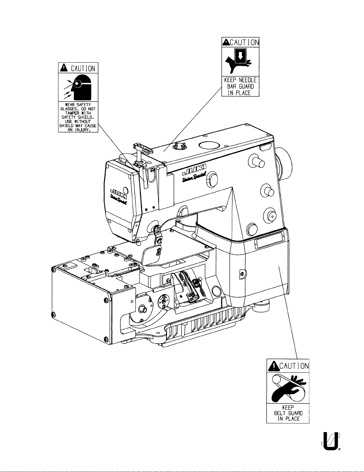
SAFETY LABLES
5
Page 6
6
Page 7

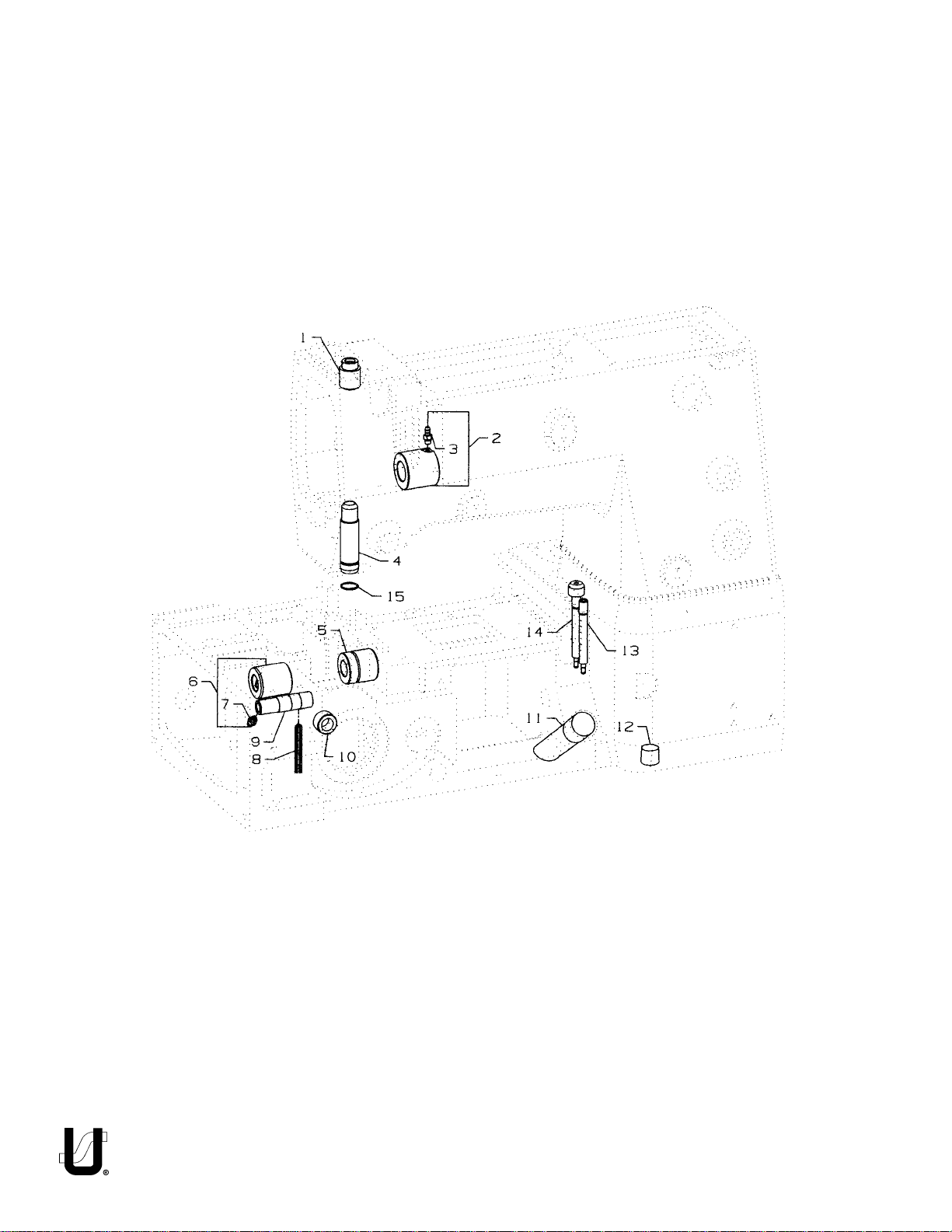
BUSHINGS
Ref.
No.
Part No.
1.
50654B
2.
50344AS
3.
SQ1110401MZ
4.
50654C
5.
50344BF
6.
50344BE
7.
SQ1110401MZ
8.
WO3
9.
50368AB
10.
50344E
11.
50393GE
12.
22571L
13.
50393FU
14.
50393EY
15.
660-1019
Description
Bushing, for needle bar, upper .....................................................................
Bushing, front ...............................................................................................
Fitting .....................................................................................................
Bushing, for needle bar, lower ......................................................................
Bushing, for lower mainshaft, right ...............................................................
Bushing, for lower mainshaft, left .................................................................
Fitting .....................................................................................................
Yarn, See Chart ............................................................................................
Bushing, for needle lever, See Chart ............................................................
Bushing ........................................................................................................
Oil Sight Gauge ............................................................................................
Screw, for drain plug ....................................................................................
Fitting, oil tube ..............................................................................................
Fitting, filter ..................................................................................................
"O"Ring .........................................................................................................
Amt.
Req.
1
1
1
1
1
1
1
1
1
1
1
1
1
1
1
7
Page 8
8
Page 9

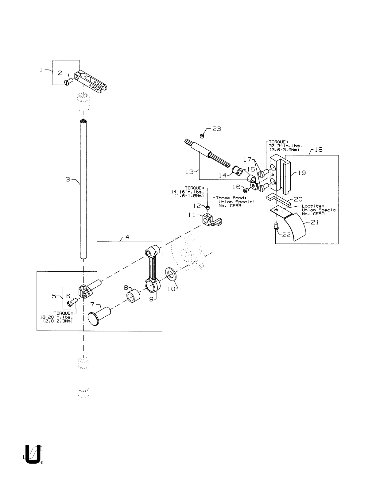
NEEDLE BAR
Ref.
No.
1.
2.
3.
4.
5.
6.
7.
8.
9.
10.
11.
-
12.
13.
14.
15.
16.
17.
18.
19.
20.
-
21.
22.
23.
Part No.
K74233
18C1419
K74234
50345W
50355AM
SS7111120TP
50352
661-259B
50355AN
50351A
50354F
CE63
SS8110422TP
29476TC
50393JZ
50393JW
SS6090440SP
SS6121010SP
29476VN
50338
666-328
CE59
50338A
SS6090620SP
SS8120410SP
Description
Needle Bar Eyelet .........................................................................................
Screw .....................................................................................................
Needle Bar ...................................................................................................
Connecting Rod Assembly ...........................................................................
Needle Bar Clamp .................................................................................
Screw ...............................................................................................
Pivot Pin .................................................................................................
Needle Bearing Cage ............................................................................
Connecting Rod ....................................................................................
Washer .........................................................................................................
Slide Block ....................................................................................................
Three Bond Adhesive, (not shown), for slide block .......................................
Screw ...........................................................................................................
Oil Tube Assembly ........................................................................................
Oil Tube ........................................................................................................
Hose Clamp .................................................................................................
Screw, for oil tube assembly .........................................................................
Screw ...........................................................................................................
Slide Block Guide and Cover Assembly ........................................................
Guide, for slide block .............................................................................
Felt, for slide block ..................................................................................
Loctite Adhesive, (not shown), for felt ...................................................
Cover, for guide .....................................................................................
Screw .....................................................................................................
Screw ...........................................................................................................
Amt.
Req.
1
1
1
1
1
1
1
1
1
1
1
1
1
1
1
1
2
1
1
1
1
1
1
9
Page 10
10
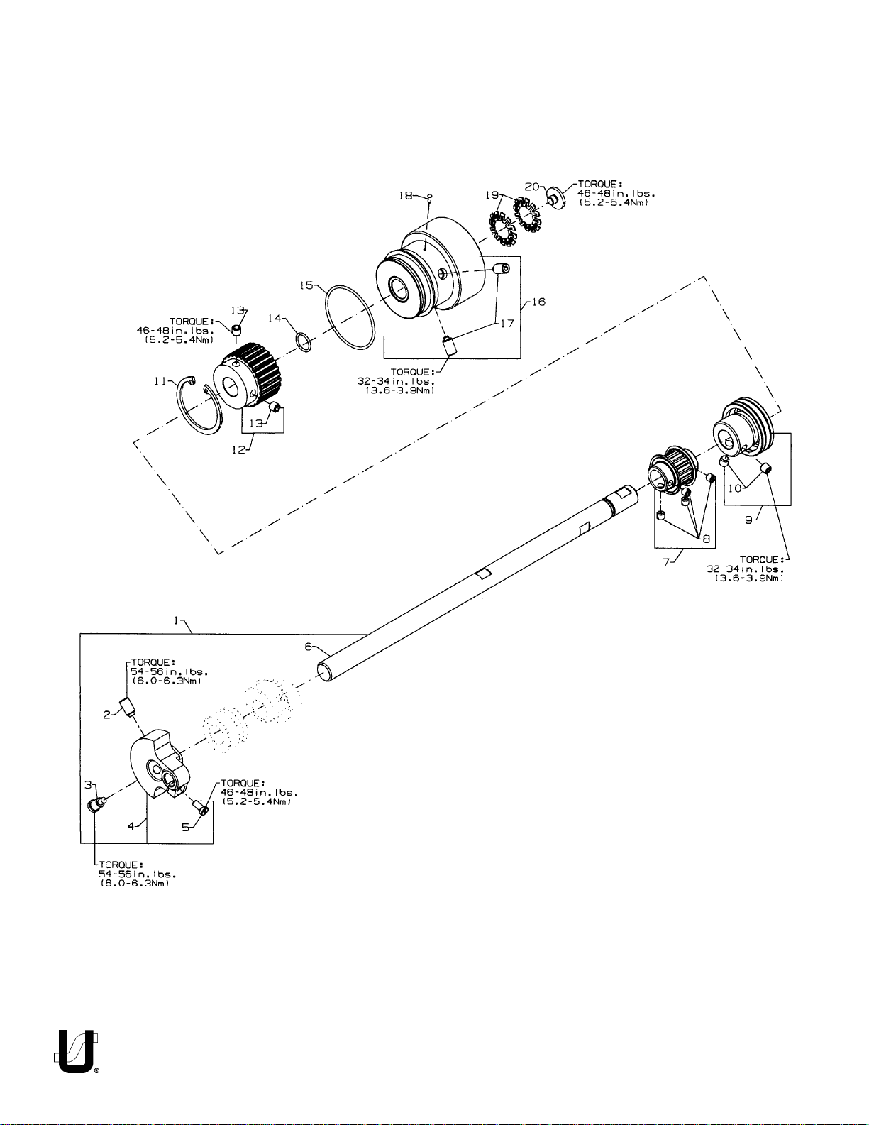
Page 11

UPPER MAIN SHAFT
Ref.
No.
1.
2.
3.
4.
5.
6.
7.
8.
9.
10.
11.
12.
13.
14.
15.
16.
17.
18.
19.
20.
Part No.
K74549
SS8681412TP
SS7681410TP
50391
SS7111120TP
K74446
50642A
22894T
50335BD
SS8660612TP
661-262
50342BE
SS8661012TP
660-1122
660-1087
K74402
SS8681412TP
660-1043
661-261
SS7660520SP
Description
Upper Needle Drive Assembly ......................................................................
Screw, for counter weight ......................................................................
Screw, for counter weight ......................................................................
Counter Weight .....................................................................................
Screw, for counter weight ...............................................................
Upper Main Shaft ...................................................................................
Puller Sprocket .............................................................................................
Screw .....................................................................................................
Bearing Adapter Assembly ...........................................................................
Screw, for bearing adapter ...................................................................
Retaining Ring ..............................................................................................
Sprocket, for upper main shaft .....................................................................
Set Screw, for sprocket ...........................................................................
"O" Ring ........................................................................................................
"O" Ring.........................................................................................................
Handwheel ..................................................................................................
Set Screw, for handwheel ......................................................................
Tack Pin, for handwheel .........................................................................
Load Ring, for lower main shaft ....................................................................
Screw, for handwheel preload ....................................................................
Amt.
Req.
1
1
1
1
1
1
1
4
1
2
1
1
2
1
1
1
2
1
2
1
.FER
.ON
1YLBMESSA.S.M.UCB2230594547KFC
6.S.M.UFA2230564447KFC
41GNIR"O"ENON2211-066FC
NOITPIRCSED
DLOWEN
REBMUNTRAP
.ONLAIRES
XIFERP
11
Page 12

12
Page 13

COVERS, UPPER ARM
Ref.
No.
1.
2.
3.
4.
5.
6.
7.
8.
9.
10.
11.
12.
13.
14.
15.
16.
17.
18.
19.
20.
21.
22.
23.
24.
25.
26.
27.
28.
29.
30.
31.
32.
33.
34.
35.
36.
Part No.
SS4121615SP
50393EU
B3530555000
660-212
K74235
50382FZ
22569M
WP0480856SP
50684B
SS6121050SP
50662A
50684C
SS4120915SP
K74239
50382FY
50382FX
SS4121215SP
TA1100604RO
TA1050504RO
SS6120940SP
SS7120710SP
605A
652C16
99682XCB
NS6620320SP
50383AE
50383AD
WZ0641510KP
SD0640323TP
SS6110610TP
99682XC3
22517B
LA452
SS7120640SP
22569M
22569C
Description
Screw, for top cover .....................................................................................
Plug, for top cover ........................................................................................
Oil Sight Gauge, top .....................................................................................
"O" Ring, for oil sight gauge ...........................................................................
Top Cover .....................................................................................................
Quad Ring, for top cover ..............................................................................
Screw ...........................................................................................................
Washer .........................................................................................................
Gasket ..........................................................................................................
Screw ...........................................................................................................
Adapter plate, for Puller Drive Housing ........................................................
Gasket ..........................................................................................................
Screw ...........................................................................................................
Adapter plate ..............................................................................................
Quad Ring, for head cover ...........................................................................
Head Cover .................................................................................................
Screw, for head cover ..................................................................................
Plug, for head cover .....................................................................................
Plug, for bed .................................................................................................
Screw ...........................................................................................................
Screw ...........................................................................................................
Screw ...........................................................................................................
Washer, for 99682XCB ..................................................................................
Protection Shield Assembly ..........................................................................
Nut .........................................................................................................
Bracket Holder .......................................................................................
Bracket ..................................................................................................
Spring Washer ........................................................................................
Shoulder Screw ......................................................................................
Counter Sunk Head Screw .....................................................................
Protection Shield ...................................................................................
Screw, for 99682XCB ....................................................................................
Label, direction of rotation ..........................................................................
Screw ...........................................................................................................
Screw ...........................................................................................................
Screw ...........................................................................................................
Amt.
Req.
6
1
1
1
1
1
4
5
1
5
1
1
2
1
1
1
4
1
1
3
1
2
1
1
1
1
1
1
1
2
1
1
1
1
4
1
13
Page 14

14
Page 15

LOWER MAIN SHAFT
Ref.
No.
1.
2.
3.
4.
5.
6.
7.
8.
9.
10.
11.
12.
13.
14.
15.
16.
17.
18.
19.
Part No.
SS7660520SP
660-1062
50374
50321G
SS8661012TP
50342AX
SS8660612TP
50342BS
K74593
K74447
50335BB
50322AL
50335AK
660-1122
50333A
SS8660612TP
660-934
K74244
SS8660410SP
Description
Shoulder Screw, for lower main shaft, right ..................................................
Spring Washer ..............................................................................................
Spacer, for pulley assembly .........................................................................
Pulley Assembly ...........................................................................................
Set Screw ...............................................................................................
Sprocket, for lower main shaft .....................................................................
Screw ....................................................................................................
Timing Belt ....................................................................................................
Mainshaft Assembly, lower, right .................................................................
Lower Main Shaft, right ..........................................................................
Retaining Ring .......................................................................................
Ball Bearing, for lower main shaft ...........................................................
Retaining Ring, for ball bearing ...................................................................
"O" Ring ........................................................................................................
Coupling, for lower main shafts ....................................................................
Screw ....................................................................................................
Oil Seal .........................................................................................................
Lower Main Shaft, left for plain feed.............................................................
Screw ....................................................................................................
Amt.
Req.
1
1
1
1
2
1
2
1
1
1
1
1
1
1
1
4
1
1
2
.FER
.ON
9YLBMESSA.S.M.LHU6749239547KFC
01THGIR,.S.M.LGA2230574447KFC
41GNIR"O"ENON2211-066FC
NOITPIRCSED
DLOWEN
REBMUNTRAP
15
.ONLAIRES
XIFERP
Page 16

16
Page 17

LUBRICATION, OIL TUBING & OIL PUMP
Ref.
No.
Part No.
1.
50393HN
2.
SS8660612TP
3.
50332S
4.
34393D
5.
50393EX
6.
SS8660612TP
7.
50393GB
8.
50393GD
9.
SS4091015SP
10.
50393FR
11.
50384
12.
11843208
13.
50393FV
14.
SS7120710SP
15.
29476XV
16.
NS6110310SP
17.
50393KC
18.
SQ1110402MZ
19.
50393KM
20.
50393-27
21.
13765607
22.
50393-47
23.
50393-407
24.
50393-89
25.
50393-51
26.
29476UT
27.
50393KH
28.
50393-70
29.
50393KM
30.
13765607
31.
50393-140
32.
50393-40
33.
50393-170
34.
SS4090815SP
35.
50393FS
36.
50393KF
37.
50393KM
38.
SS6151812TP
39.
WS0631510KP
40.
22571E
41.
RM2871B
42.
50393EB
43.
50384A
44.
50393FT
45.
50393KN
Description
Oil Pump Assembly, 2-stage .........................................................................
Screw .....................................................................................................
Spring, for plunger..................................................................................
Plunger ..................................................................................................
Collar, for oil pump .................................................................................
Screw ...............................................................................................
Oil Pump Housing, 2 Stage......................................................................
Oil Pump Housing, 2 Stage......................................................................
Screw, for oil filter cover................................................................................
Cover, for oil filter..........................................................................................
"O" Ring, for oil filter cover.............................................................................
Oil Filter.........................................................................................................
Oil Tube, for supply (1) ..................................................................................
Screw, for front upper tube ..........................................................................
Oil Supply Assembly, upper ..........................................................................
Nut .........................................................................................................
Oil Gutter ...............................................................................................
Fitting .....................................................................................................
Tube Retaining, spring ...........................................................................
Oil Tube ..................................................................................................
"T" Connector .........................................................................................
Oil Tube ..................................................................................................
Oil Tube ..................................................................................................
Oil Tube ..................................................................................................
Oil Tube ..................................................................................................
Oil Supply Assembly, lower ...........................................................................
Tube Retaining, spring ...........................................................................
Oil Tube ..................................................................................................
Tube Retaining, spring ...........................................................................
"T" Connector .........................................................................................
Oil Tube ..................................................................................................
Oil Tube ..................................................................................................
Oil Tube ..................................................................................................
Screw, for oil tube holder ..............................................................................
Oil Tube Holder .............................................................................................
Oil Tube ........................................................................................................
Tube Retaining, spring ..................................................................................
Screw, for oil pan ..........................................................................................
Spring Washer ..............................................................................................
Screw, for oil drain plug ................................................................................
Cable Tie ......................................................................................................
Oil Pan ..........................................................................................................
"O" Ring ........................................................................................................
Oil Tube, for suction ......................................................................................
Pump Cap For Inlet "C" .................................................................................
Amt.
Req.
1
2
2
2
1
2
1
1
3
1
1
1
1
2
1
1
1
1
7
1
2
1
1
1
1
1
2
1
5
2
1
1
1
1
1
1
3
6
6
1
2
1
1
1
1
17
Page 18

18
Page 19

LOOPER DRIVE
Ref.
No.
1.
-
2.
3.
4.
5.
6.
7.
8.
9.
10.
11.
12.
13.
14.
15.
16.
17.
18.
Part No.
SS7120710SP
CE63
660-893
50344AM
50384M
660-1113
50313J
SS7120910SP
50314J
50314E
50642
22653J8
667J33
660-979
50342BJ
SS8660612TP
50342BK
SS8660612TP
50342BY
Description
Screw, for bearing housing ..........................................................................
Three Bond Adhesive, (not shown), for screw ..............................................
Oil Seal, looper .............................................................................................
Bearing Housing Assembly, for looper drive .................................................
Gasket, for Bearing Housing Assembly .........................................................
"O" Ring, for bearing housing assembly ........................................................
Looper Rocker Assembly .............................................................................
Screw, for retaining plate ............................................................................
Eccentric Retaining Plate ............................................................................
Looper Avoid Adjusting Eccentric ...............................................................
Looper Drive Assembly ................................................................................
Screw ....................................................................................................
Crank Pin ...............................................................................................
"O" Ring ..................................................................................................
Sprocket, for looper driven ..........................................................................
Screw ....................................................................................................
Sprocket, for looper drive ............................................................................
Screw ....................................................................................................
Looper Drive Belt ..........................................................................................
Amt.
Req.
3
1
1
1
1
1
2
1
1
1
1
1
2
1
2
1
2
1
.FER
.ON
8ETALPEDIUGF41305J41305CD
NOITPIRCSED
DLOWEN
REBMUNTRAP
.ONLAIRES
XIFERP
19
Page 20

20
Page 21

NEEDLE GUARD
Ref.
No.
1.
50373DA
2.
SS8110422TP
3.
50368W
4.
50668
5.
SS8110422TP
6.
50368E
7.
50368A
8.
50374
9.
50622C
10.
RC0560711KP
11.
50625
12.
SS6090620SP
Part No.
Description
Needle Guard Eccentric .............................................................................
Screw, for needle guard eccentric .......................................................
Connecting Rod Assembly, for needle guard ..............................................
Pivot Link ......................................................................................................
Screw .....................................................................................................
Washer .........................................................................................................
Pivot Pin ........................................................................................................
Washer .........................................................................................................
Shaft, for needle guard ................................................................................
Retaining Ring .......................................................................................
Rear Needle Guard holder ..........................................................................
Screw .....................................................................................................
Amt.
Req.
1
2
1
1
2
2
1
1
1
2
1
2
21
Page 22

22
Page 23

LOOPER THREAD TAKE-UP
Ref.
No.
1.
2.
3.
4.
5.
6.
7.
8.
9.
10.
11.
12.
13.
14.
15.
16.
17.
18.
19.
20.
21.
22.
23.
24.
25.
26.
27.
28.
29.
30.
31.
Part No.
K74440
51959D
51959K
51959L
51959B
51492
50358H
SS6060440TP
50304H
WP0330501SP
SS9080410SP
41358
50604
SS7080520SP
50383E
50357W
SS9111010SP
SS6110610TP
29476UK
SS7092110TP
50383F
50304K
50386J
SD0630275SP
50623
22894C
50323B
22-348
50377R
50623A
77B
Description
Cast-Off Plate Assembly ...............................................................................
Knurled Nut ............................................................................................
Tension Spring ........................................................................................
Roll Pin ....................................................................................................
Tension Disc ...........................................................................................
Tension Post ...........................................................................................
Take-up Eyelet .......................................................................................
Screw .....................................................................................................
Strike-Off Wire ........................................................................................
Washer ...................................................................................................
Screw .....................................................................................................
Washer ...................................................................................................
Retaining Finger .....................................................................................
Screw .....................................................................................................
Mounting Bracket ..................................................................................
Cast-Off Plate ........................................................................................
Screw, for collar bracket ..............................................................................
Screw, for cast-off holder .............................................................................
Cast-Off Plate Holder Assembly ...................................................................
Screw, for collar bracket ........................................................................
Take-up Collar Bracket ..........................................................................
Cast-Off Plate Holder .............................................................................
Washer ...................................................................................................
Shoulder Screw, for cast-off plate holder ...............................................
Take-up Assembly ........................................................................................
Set Screw ...............................................................................................
Take-up Hub ...........................................................................................
Pin ....................................................................................................
Spacer ...................................................................................................
Disc, for take-up .....................................................................................
Screw, for take-up disc ..........................................................................
Amt.
Req.
1
1
1
1
2
1
3
4
1
1
1
2
1
2
1
1
1
1
1
1
1
1
1
1
1
2
1
2
1
2
2
23
Page 24

24
Page 25

COVERS, LOWER BED
Ref.
No.
1.
2.
3.
4.
5.
6.
-
7.
8.
9.
10.
11.
12.
13.
14.
15.
16.
17.
18.
19.
20.
Part No.
K74261
K74214
SS4151415SP
SS4120615SP
50382CL
50382CR
CE63
SS6121212TP
50382CP
K74246
SS7120640SP
K74312
50303B
50393HU
SS4121015SP
K74247
22841U
50383G
50382CG
SS7090850SP
SS7150740SP
Description
Gasket, for left end cover ............................................................................
Left End Cover .............................................................................................
Screw ...........................................................................................................
Screw, for cover ...........................................................................................
Cover, rear, for feed chamber, ....................................................................
Gasket .........................................................................................................
Three Bond Adhesive, (not shown), for screw ...............................................
Screw, for cover ...........................................................................................
Cover, for feed chamber .............................................................................
Gasket .........................................................................................................
Screw ...........................................................................................................
Cloth Plate, right ..........................................................................................
Acoustic Pad .........................................................................................
Plug, right end , non-synchronizer ................................................................
Screw ...........................................................................................................
Cover, for drive belt .....................................................................................
Machine Support Stud .................................................................................
Gasket, for chamber cover ..........................................................................
Dry Chamber Cover .....................................................................................
Screw ...........................................................................................................
Screw ...........................................................................................................
Amt.
Req.
1
1
4
2
1
1
6
1
1
6
1
1
1
4
1
4
1
1
8
2
25
Page 26

26
Page 27

PULLER DRIVE ASSEMBLY
Ref.
No.
1.
2.
3.
4.
5.
6.
7.
8.
9.
10.
11.
12.
13.
14.
15.
16.
17.
18.
19.
20.
21.
22.
23.
24.
25.
26.
27.
28.
29.
30.
31.
32.
33.
34.
35.
36.
37.
Part No.
29476XW
660-893
22564J
C50082AP
660-886A
660-914
660-918
660-890
136
50677A
660-886B
660-891B
C50078L
660-889
C50078M
C50078K
C50078J
22593
C50078N
50677
22894J
660-886C
660-892C
C50078P
661-70A
C50022L
C50042AC16
98
660-891C
660-888
59451F
22574D
C50082AR
22524
C50042AF
671F19A
671F64
Description
Puller Drive Assembly ...................................................................................
Lip Seal ..................................................................................................
Screw .....................................................................................................
Cover ....................................................................................................
"O" Ring ..................................................................................................
Finger Spring ..........................................................................................
Retaining Ring .......................................................................................
Bearing ..................................................................................................
Screw .....................................................................................................
Bearing Housing .....................................................................................
"O" Ring ..................................................................................................
Snap Ring ...............................................................................................
Internal Gear .........................................................................................
Bearing ..................................................................................................
Internal Gear .........................................................................................
Pin ...................................................................................................
Slide Block ..............................................................................................
Screw .....................................................................................................
Guide Ring .............................................................................................
Puller Drive Housing ...............................................................................
Screw .....................................................................................................
"O" Ring ..................................................................................................
Bearing ..................................................................................................
Eccentric Housing .................................................................................
Snap Ring ...............................................................................................
Eccentric Drive Shaft .............................................................................
Sprocket ................................................................................................
Screw ..............................................................................................
Snap Ring ...............................................................................................
Bearing ..................................................................................................
Washer ..................................................................................................
Screw .....................................................................................................
Cover ....................................................................................................
Screw .....................................................................................................
Timing Belt ..............................................................................................
Barb Fitting ...................................................................................................
Extension Fitting ...........................................................................................
Amt.
Req.
1
1
3
1
2
2
1
1
2
1
1
1
1
1
1
1
1
1
1
1
1
1
1
1
1
1
1
2
1
1
1
1
1
3
1
1
1
27
Page 28

28
Page 29

ACCESSORIES
Ref.
No.
Part No.
1.2.35095B
28604R
Amt.
Description
Isolator .........................................................................................................
Oil, (1 pint) ....................................................................................................42
Req.
29
Page 30

NUMERICAL INDEX OF PARTS
Part No. Page No.
11843208 ............17
136 ....................27
13765607 ..........17
18C1419 ................9
22-348 ..............23
22517B .............13
22524 ...............27
22564J ............27
22569M ............13
22571E ............17
22571L ............7
22574D ............27
22593 ..............27
22653J8 ............19
22841U ............25
22894C ............23
22894J ............27
22894T ............11
28604R ............29
29476TC ............9
29476UK ............23
29476UT ..........17
29476VN ............9
29476XV ..........17
29476XW ..........27
34393D ............17
35095B ............29
41358 .............23
50303B ............25
50304H ............23
50304K ............23
50313J ............19
50314E ............19
50314J ............19
50321G ............15
50322AL ...........15
50323B ............23
50332S ............17
50333A ............15
50335AK ..........15
50335BB ..........15
50335BD ..........11
50338 ..............9
50338A ............9
50342AX ..........15
50342BE ..........11
50342BJ ..........19
50342BK ..........19
50342BS ..........15
50342BY ..........19
50344AM ..........19
50344AS ............7
50344BE ...........7
50344BF ...........7
50344E .............7
Part No. Page No.
50345W .............9
50351A .............9
50352 ..............9
50354F ............9
50355AM ...........9
50355AN ...........9
50357W ............23
50358H ............23
50368A ............21
50368AB ...........7
50368E ............21
50368W ............21
50373DA ...........21
50374 .......15, 21
50377R ............23
50382CG ...........25
50382CL ..........25
50382CP ..........25
50382CR ..........25
50382FX ..........13
50382FY ..........13
50382FZ ..........13
50383AD ..........13
50383AE ..........13
50383E ............23
50383F ............23
50383G ............25
50384 .............17
50384A ............17
50384M ............19
50386J ............23
50391 .............11
50393-140 .........17
50393-170 .........17
50393-27 ..........17
50393-40 ..........17
50393-407 .........17
50393-47 ..........17
50393-51 ..........17
50393-70 ..........17
50393-89 ..........17
50393EB ..........17
50393EU ..........13
50393EX ..........17
50393EY ...........7
50393FR ..........17
50393FS ..........17
50393FT ..........17
50393FU ...........7
50393FV ...........17
50393GB ...........17
50393GD ...........17
50393GE ............7
50393HN ..........17
50393HU ..........25
Part No. Page No.
50393JW ............9
50393JZ ............9
50393KC ..........17
50393KF ..........17
50393KH ..........17
50393KM ..........17
50393KN ..........17
50604 ...............23
50622C .............21
50623 ...............23
50623A .............23
50625 ...............21
50642 ...............19
50642A .............11
50654B ..............7
50654C ..............7
50662A .............13
50668 ...............21
50677 ...............27
50677A .............27
50684B .............13
50684C .............13
51492 ...............23
51959B .............23
51959D .............23
51959K .............23
51959L .............23
59451F .............27
605A ...............13
652C16 ...........13
660-1019 .............7
660-1043 ...........11
660-1062 ...........15
660-1087 ...........11
660-1113 ...........19
660-1122 .....11, 15
660-212 ...........13
660-886A .........27
660-886B .........27
660-886C .........27
660-888 ...........27
660-889 ...........27
660-890 ...........27
660-891B .........27
660-891C .........27
660-892C .........27
660-893 .....19, 27
660-914 ...........27
660-918 ...........27
660-934 ...........15
660-979 ...........19
661-259B ...........9
661-261 ...........11
661-262 ...........11
661-70A ...........27
Part No. Page No. Part No. Page No.
666-328 ............9
667J33 ...........19
671F19A ...........27
671F64 ............27
77B ...............23
98 .................27
99682XC3 .........13
99682XCB .........13
B3530555000 ....13
C50022L ...........27
C50042AC16......27
C50042AF .........27
C50078J ...........27
C50078K ...........27
C50078L ...........27
C50078M ..........27
C50078N ...........27
C50078P ...........27
C50082AP .........27
C50082AR .....27
CE59 ................9
CE63 .....9, 19, 25
K74214 .............25
K74233 ..............9
K74234 ..............9
K74235 ...........13
K74239 ...........13
K74244 ...........15
K74246 ...........25
K74247 ...........25
K74261 ...........25
K74312 ...........25
K74402 ...........11
K74440 ...........23
K74446 ...........11
K74447 ...........15
K74549 .....11
K74593 .....15
LA452 .....13
NS6110310SP .....17
NS6620320SP .....13
RC0560711KP .....21
RM2871B ..........17
SD0630275SP .....23
SD0640323TP .....13
SQ1110401MZ .....7
SQ1110402MZ .....17
SS4090815SP .....17
SS4091015SP .....17
SS4120615SP .....25
SS4120915SP .....13
SS4121015SP .....25
SS4121215SP .....13
SS4121615SP .....13
SS4151415SP .....25
SS6060440TP .....23
SS6090440SP .....9
SS6090620SP .....9
SS6090620SP .....21
SS6110610TP .....13
SS6110610TP .....23
SS6120940SP .....13
SS6121010SP .....9
SS6121050SP .....13
SS6121212TP .....25
SS6151812TP .....17
SS7080520SP .....23
SS7090850SP .....25
SS7092110TP .....23
SS7111120TP .....9
SS7111120TP .....11
SS7120640SP .....13
SS7120640SP .....25
SS7120710SP .....13
SS7120710SP .....17
SS7120710SP .....19
SS7120910SP .....19
SS7150740SP .....25
SS7660520SP .....11
SS7660520SP .....15
SS7681410TP .....11
SS8110422TP .....9
SS8110422TP .....21
SS8120410SP .....9
SS8660410SP .....15
SS8660612TP .....11
SS8660612TP .....15
SS8660612TP .....17
SS8660612TP .....19
SS8661012TP .....11
SS8661012TP .....15
SS8681412TP .....11
SS9080410SP .....23
SS9111010SP .....23
TA1050504RO .....13
TA1100604RO .....13
WO3 ........................7
WP0330501SP .....23
WP0480856SP .....13
WS0631510KP .....17
WZ0641510KP .....13
30
Page 31

NOTES
31
Page 32

 Loading...