

Page 1

STYLES
FS311L41
ILLUSTRATED PARTS LIST
FS300 SERIES, DIFFERENTIAL FEED,
HIGH SPEED FLAT BED MACHINES
CATALOG NO.
PT0105
FIRST EDITION
SUPPLEMENT TO
PT9808
03/22/05
Page 2

Page 3

SPREADER ADJUSTMENTS
1) Timing
Just when the needle descends 2.5 mm from the
highest point of the needle bar, the spreader
begins to return from its extreme left position.
3) Position of spreader
2) Stroke
• The height is 12.5 ±0.2 mm
• When the spreader is in the extreme left position,
the distance between the center of the left
needle and the top blade of the spreader is
6.4 ±0.1 mm.
• When the spreader returns to the right, the
clearence between the spreader and the left
needle is 0.8 mm.
4) Fixing spreader thread guide
5) Needle clamp spreader thread guide
• When the spreader is in the extreme right position,
the top blade of the sperader should be between
the left side and middle of the spreader thread
guide groove.
• The height is 0.4 to 0.8 mm from the surface of the
spreader.
• When the needle bar is in the lowest position, the
clearance between the needle clamp spreader
thread guide and the upper face of the fixing
spreader thread guide is 2.0 ±0.5 mm.
• The center of the hole of the thread guide aligns
with the left side of the fixing spreader thread
guide groove.
3
Page 4
4
Page 5

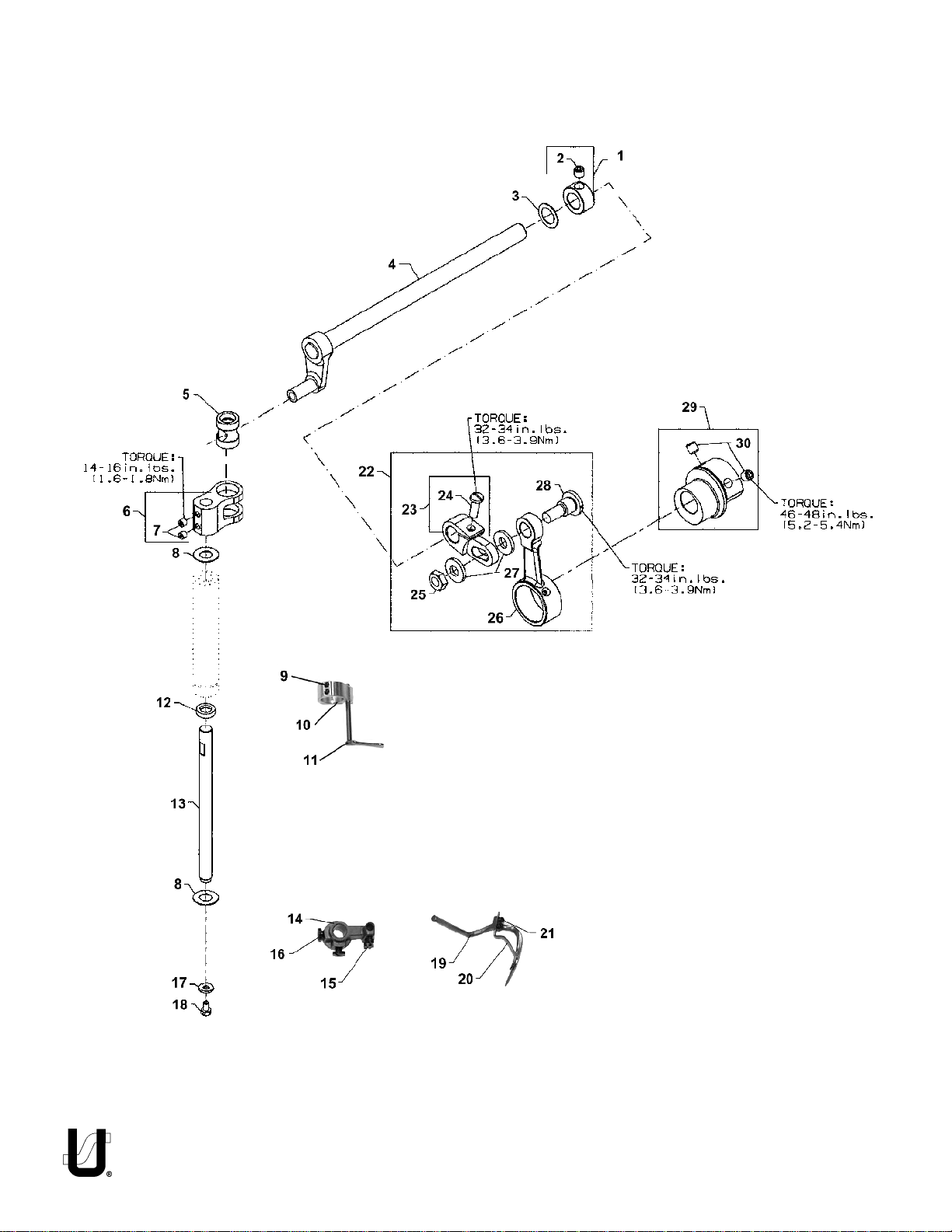
SPREADER
Ref.
No.
1.
2.
3.
4.
5.
6.
7.
8.
9.
10.
11.
12.
13.
14.
15.
16.
17.
18.
19.
20.
21.
22.
23.
24.
25.
26.
27.
28.
29.
30.
.
Part No.
50335AW
SS8660512TP
96162B
50360B
50347J
50347C
SS8110422TP
61351C
SS8080310TP
K74382
57845E
660-739
50347G
57845G
77
94
53678N
SS9090640SP
K74383
57845F
22738B
29126FW
50360G
SS7121410TP
NS6680410SP
50360F
WP0742016SP
SD1000801SH
50360
SS8660612TP
Description
Collar, for spreader shaft ............................................................................
Set Screw ..............................................................................................
Washer ........................................................................................................
Crankshaft, for spreader assembly .............................................................
Pin, for spreader rocker ...............................................................................
Lever, for spreader holder shaft ..................................................................
Screw ....................................................................................................
Washer ........................................................................................................
Screw ..........................................................................................................
Collar ..........................................................................................................
Spreader Thread Guide ..............................................................................
Oil Seal ........................................................................................................
Shaft, for spreader, vertical ........................................................................
Spreader Holder ..........................................................................................
Screw ....................................................................................................
Screw ....................................................................................................
Washer ........................................................................................................
Hex Screw, for vertical shaft ........................................................................
Spreader .....................................................................................................
Auxiliary Spreader .......................................................................................
Screw ..........................................................................................................
Spreader Crank Rod Assembly ....................................................................
Spreader Shaft Driving Arm ...................................................................
Screw .............................................................................................
Hex Nut, for spreader drive ...................................................................
Connecting Rod, for spreader drive .....................................................
Collar, for spreader driving arm ............................................................
Stud ......................................................................................................
Eccentric, for spreader drive ......................................................................
Screw ....................................................................................................
Amt.
Req.
1
1
1
1
1
1
2
2
3
1
1
1
1
1
2
2
1
1
1
1
2
1
1
1
1
1
2
1
1
2
*NOTE: SOME "K" PARTS SHOWN ARE NOT PICTORIALLY CORRECT
5
Page 6
6
Page 7

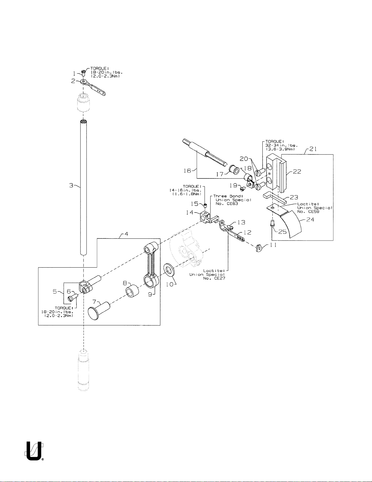
NEEDLE BAR
Ref.
No.
10.
11.
12.
13.
14.
15.
16.
17.
18.
19.
20.
21.
22.
23.
24.
25.
.
Part No.
1.
SS4080620TP
2.
50323P
3.
K74313
4.
50645A
5.
50355AM
6.
SS7111120TP
7.
50352
8.
661-259B
9.
50645
50351A
50393JP
50358X
SS7080520SP
-
CE27
50354F
-
CE63
SS8110422TP
29476TC
50393JZ
50393JW
SS6090440SP
SS6121010SP
29476VN
50338
666-328
-
CE59
50338A
SS6090620SP
Description
Screw ...........................................................................................................
Needle Bar Eyelet .........................................................................................
Needle Bar ...................................................................................................
Connecting Rod Assembly ...........................................................................
Needle Bar Clamp .................................................................................
Screw ...............................................................................................
Pivot Pin .................................................................................................
Needle Bearing Cage ............................................................................
Connecting Rod ....................................................................................
Washer .........................................................................................................
Eyelet Seal ....................................................................................................
Needle Thread Eyelet ...................................................................................
Screw ...........................................................................................................
Loctite Adhesive, (not shown), for screw .....................................................
Slide Block ....................................................................................................
Three Bond Adhesive, (not shown), for slide block .......................................
Screw ...........................................................................................................
Oil Tube Assembly ........................................................................................
Oil Tube ........................................................................................................
Hose Clamp .................................................................................................
Screw, for oil tube assembly .........................................................................
Screw ...........................................................................................................
Slide Block Guide and Cover Assembly ........................................................
Guide, for slide block .............................................................................
Felt, for slide block ..................................................................................
Loctite Adhesive, (not shown), for felt ...................................................
Cover, for guide .....................................................................................
Screw .....................................................................................................
Amt.
Req.
1
1
1
1
1
1
1
1
1
1
1
1
1
-
1
1
1
1
1
1
2
1
1
1
1
1
*NOTE: SOME "K" PARTS SHOWN ARE NOT PICTORIALLY CORRECT
7
Page 8

8
Page 9

LOOPER DRIVE
Ref.
No.
1.
2.
3.
4.
5.
6.
7.
8.
9.
10.
11.
12.
13.
14.
15.
16.
17.
18.
19.
20.
21.
22.
23.
.
Part No.
50313F
22565X
22575B
22652B10
50309H
51508BV16
SS7120910SP
CE63
660-893
50344AM
660-455
50313J
SS7120910SP
50314F
50314E
50642
22653J8
667J33
660-979
50342BJ
SS8660612TP
50342BK
SS8660612TP
50324BP
Description
Looper Holder ..............................................................................................
Screw, for looper holder ........................................................................
Screw, for looper holder ........................................................................
Screw, for looper holder ........................................................................
Looper, Rear ................................................................................................
Looper, Front ...............................................................................................
Screw, for bearing housing ..........................................................................
Three Bond Adhesive, (not shown), for screw ..............................................
Oil Seal, looper .............................................................................................
Bearing Housing Assembly, for looper drive .................................................
"O" Ring, for bearing housing assembly ........................................................
Looper Rocker Assembly .............................................................................
Screw, for retaining plate ............................................................................
Eccentric Retaining Plate ............................................................................
Looper Avoid Adjusting Eccentric ...............................................................
Looper Drive Assembly ................................................................................
Screw ....................................................................................................
Crank Pin ...............................................................................................
"O" Ring ..................................................................................................
Sprocket, for looper driven ..........................................................................
Screw ....................................................................................................
Sprocket, for looper drive ............................................................................
Screw ....................................................................................................
Looper Drive Belt ..........................................................................................
Amt.
Req.
1
1
2
1
1
1
3
1
1
1
1
2
1
1
1
1
1
2
1
2
1
2
1
*NOTE: SOME "K" PARTS SHOWN ARE NOT PICTORIALLY CORRECT
9
Page 10

10
Page 11

NEEDLE GUARD
Ref.
No.
1.
2.
3.
4.
5.
6.
7.
8.
9.
10.
11.
12.
.
Part No.
50373DA
SS8110422TP
50368W
50668
SS8110422TP
50368E
50368A
50622C
RC0560711KP
50625
SS6090620SP
50325L
Description
Needle Guard Eccentric .............................................................................
Screw, for needle guard eccentric .......................................................
Connecting Rod Assembly, for needle guard ..............................................
Pivot Link ......................................................................................................
Screw .....................................................................................................
Washer .........................................................................................................
Pivot Pin ........................................................................................................
Shaft, for needle guard ................................................................................
Retaining Ring .......................................................................................
Holder, for needle guard .............................................................................
Screw .....................................................................................................
Needle Guard, Rear .....................................................................................
*NOTE: SOME "K" PARTS SHOWN ARE NOT PICTORIALLY CORRECT
Amt.
Req.
1
1
2
1
1
2
2
1
1
1
2
1
11
Page 12

12
Page 13

COVERS, LOWER BED
Ref.
No.
1.
2.
3.
4.
5.
6.
7.
8.
9.
10.
11.
12.
13.
14.
15.
16.
17.
18.
19.
20.
21.
.
-
Part No.
18-1448
K74380
50601E
50303B
SS6121212TP
50382CL
50382CS
22839C
50382CG
50382CR
SS7150740SP
22587N
35036AE
K74391
51280K
660-939
C067D
22517
50382CR
50382CL
SS4120615SP
CE63
Description
Screw ...........................................................................................................
Cloth Plate, left ............................................................................................
Cloth Plate, right ..........................................................................................
Acoustic Pad .........................................................................................
Screw, for cover ...........................................................................................
Cover, for feed chamber .............................................................................
Gasket .........................................................................................................
Screw, for cover ...........................................................................................
Cover, for dry chamber ...............................................................................
Gasket, for dry chamber cover ....................................................................
Screw ...........................................................................................................
Screw ...........................................................................................................
Ferrule, Locating ..........................................................................................
Throat Plate Support, complete ...................................................................
Pin ..........................................................................................................
Rubber Bumper, for Throat Plate Support ..............................................
Cork .............................................................................................................
Screw, for bed ..............................................................................................
Gasket .........................................................................................................
Cover, rear, for feed chamber, ....................................................................
Screw, for cover ...........................................................................................
Three Bond Adhesive, (not shown), for screw ...............................................
Amt.
Req.
11
1
1
1
6
1
1
3
1
1
2
2
2
1
1
1
2
2
1
1
2
-
*NOTE: SOME "K" PARTS SHOWN ARE NOT PICTORIALLY CORRECT
13
Page 14

14
Page 15

COVERS, LOWER BED
Ref.
No.
1.
2.
3.
4.
5.
6.
7.
8.
9.
10.
11.
12.
13.
14.
15.
16.
17.
18.
19.
20.
21.
22.
23.
24.
25.
26.
27.
28.
29.
30.
31.
32.
33.
.
Part No.
50393HB
50684A
50682B
SS4151415SP
50393HA
WO3
22841U
50383G
50382CG
SS7090850SP
50378S
SS9110543CP
660-1020
SS6120930TP
20
50382T
50393W
22519J
K74379
22729D
50667
SS4121015SP
50393HU
50382CJ
50332A
39250J
22513D
50382FP
25CC
35569J
50332B
SS7120710SP
22799AH
Description
Plug, for bed .................................................................................................
Quad Ring, for left end cover .......................................................................
Left End Cover ..............................................................................................
Screw ...........................................................................................................
Plug ..............................................................................................................
Oil Wick, for needle guard ............................................................................
Machine Support Stud ..................................................................................
Gasket, for chamber cover ..........................................................................
Dry Chamber Cover .....................................................................................
Screw ...........................................................................................................
Hinge ............................................................................................................
Screw ...........................................................................................................
Rubber Bumper ............................................................................................
Screw ...........................................................................................................
Washer .........................................................................................................
Stop, for front cover ......................................................................................
Rubber Bumper ............................................................................................
Screw ...........................................................................................................
Swing Down Cover .......................................................................................
Screw ...........................................................................................................
Lever ............................................................................................................
Screw ...........................................................................................................
Plug, right end, non-synchronizer .................................................................
Cover, for drive belt .....................................................................................
Latch Spring .................................................................................................
Nut ................................................................................................................
Screw ...........................................................................................................
Latch, looper throw-out safety .....................................................................
Screw ...........................................................................................................
Nut ................................................................................................................
Support Block ...............................................................................................
Screw ...........................................................................................................
Spring Latch Stud ..........................................................................................
Amt.
Req.
2
1
1
4
1
1
4
1
1
8
2
4
2
4
2
2
2
2
1
2
1
4
1
1
2
2
2
1
2
1
1
2
2
*NOTE: SOME "K" PARTS SHOWN ARE NOT PICTORIALLY CORRECT
15
Page 16

LEDOMDAEHELDEEN
4Z46H2-14L113SF
H2-14L113SF
3Z1CC46
TOOFRESSERP
YLBMESSA
59347K46FP0260561-0289A21DA50415
ETALPTAORHTGODDEEF
16
Page 17

SEWING PARTS
Ref.
No.
1.
2.
3.
4.
.
-
-
-
-
-
-
-
-
-
-
-
-
-
-
-
-
Part No.
50620PF64
SS6060440TP
50630PF
91
51430F
22840A
50630PF64
50630PF1
51430F
96651
61330B44
A9820-16
K74395
22KH
K74314
28C
1096
50342Z
660-219AH
51405AD12
Description
Presser Foot ..................................................................................................
Screw .....................................................................................................
Presser Foot Shank .................................................................................
Screw ..............................................................................................
Nut ...................................................................................................
Screw ..............................................................................................
Presser Foot Bottom ...............................................................................
Guide ....................................................................................................
Nut .........................................................................................................
Roll Pin ...................................................................................................
Presser Foot Hinge Pin ............................................................................
Throat Plate ..................................................................................................
Needle Head ...............................................................................................
Screw .....................................................................................................
Thread Eyelet .........................................................................................
Set Screw ...............................................................................................
Set Screw ...............................................................................................
Needle Thread Guide ............................................................................
Roll Pin ...................................................................................................
Feed Dog .....................................................................................................
*NOTE: SOME "K" PARTS SHOWN ARE NOT PICTORIALLY CORRECT
Amt.
Req.
1
1
1
1
1
1
1
1
1
1
1
1
1
1
1
2
1
1
2
1
17
Page 18

NOTES
18
Page 19

NOTES
19
Page 20

 Loading...