

Page 1
Finest Quality
OPERATOR /ILLUSTRATED PARTS MANUAL
FS300 SERIES, PLAIN AND DIFFERENTIAL FEED,
HIGH SPEED FLAT BED MACHINES
MANUAL NO. PT9605
FOR STYLES
FS311S01 FS311S13
FS311S02 FS311S14
FS311S11
FS311S21
FS311S12
REV
11--07-98
Page 2

Manual
No.
PT9605
llustrated Parts
List
for
FS300
Series
Machines
This
parts
manual
can
be
used in
It
is
the
desire
specifically
This
manual
incorporate a slight
On
the
following
conjunction
of
Union
for
your
has
been
pages
Union
has
been
Special
machine
comprised
modification
are
Special
prepared
with
Union
that
each
and
are
on
of
illustrations
Second
Corporation
Printed
to
assist you
Special
machine
manufactured
the
configuration
and
Engineer's
basis
of
terminology
Edition
Copyright
By
Rights Reserved
in
U.S.A. Sept. 1998
PREFACE
in
locating
run
at
with
available
in
illustrations
Manual
its
optimum
utmost
information.
used
individual
in
parts
EN9424.
performance.
precision
Changes
or
port
numbers.
describing
1998
In
All
or assemblies
Parts listed in this
to
assure
in
the
parts
Countries
on
FS300
long
lasting
design
used
and/or
on
FS300 Series
Series
machines.
manual
service.
are
improvements
machines.
It
designed
may
2
Page 3

CONTENTS
PREFACE
IDENTIFICATION
CLASS
STYLE
ILLUSTRATIONS
IDENTIFYING
NEEDLES
SAFETY
CAUTION
OPERATOR'S
OPERATING
OPERATING
OPERATING
LUBRICATION:
THREADING
THREADING
THREADING
THREADING
ADJUSTING
PRESSER
BUSHINGS............... . .............................................................................................................................
NEEDLE
UPPER
THREAD
TENSION
PRESSER
COVERS.
LOWER
LUBRICATION,
LOOPER
NEEDLE
LOOPER
FEED
FEED
FEED
FEED
COVERS,
COVERS.
COVERS,
SEWING
TABLING
ACCESSORIES
NUMERICAL
NUMERICAL
NOTES...
NOTES
............................................................... .................... ............................................................. .
OF
MACHINES
DESCRIPTION
OF
MACHINES...............................
PARTS
........................................................................................................................................................... 5
RULES
MAIN
DRIVE
DRIVE
DRIVE
DRIVE
.................................................................................................................................................................
........................................................................................................................................................ 6
AREAS:
DAILY
CAUTIONS:
CAUTIONS
THE
THE
THE
THE
MEDTHODS
THE
FOOT
BAR...........
SHAFT
GUIDE
RELEASE & THREAD
FOOT
UPPER
MAIN SHAFT.......................................................................................................................................
DRIVE
GUARD.......................................
THREAD
MECHANISM
MECHANISM
MECHANISM
MECHANISM
LOWER
LOWER
LOWER
PARTS
AND
INDEX
INDEX
.......................................................................................................................................... 4
.......................................................................................................................................................... 5
.................................................................................................................................................. 5
......................................................................................................................................... 8
CHECK
......................................................................................................................................... 9
(CONT.): ........................................................................................................................
PEDALS:
.........................................................................................................................................................
MACHINE:
MACHINE (CONT.): ...................................................................................................................
MACHINE (CONT.): ...................................................................................................................
........................................................................................................................................
STITCH
PRESSURE
.......................................................................................................................................................
LIFT
OIL
......................................................................................................................................................
.......................................................................................................................................................
NEEDLE
......................................................................................................................................................
.................................... ............ .
LENGTH:
..
................................................................................................................................................
................................................................................................................................................
ARM
...
TUBING & OIL
TAKE-UP............................ ............... . .................................................
BED
............................................................................................................................................
BED
FOR
BED
FOR
DIPPER
OF
PARTS
OF
PARTS
.................................................................................................................... 4
......
..........
LIST:............................................. . ...................
......................................................................................................................................
..................................................................................................................................
..........................................................................................................................
AND
LIFTER:
..............................................................................................................................
TENSION
..............................
FOR
PLAIN
FOR
DIFFERENTIAL
FOR
PLAIN
FOR
DIFFERENTIAL
PLAIN
DIFFERENTIAL
ASSEMBLY
..............................................................................................................................
............................................................................................................................
............................................................................................................
................................................................................................................
..
. ..........................
PUMP
..............................................................................................................
..
................................................................................................
FEED
...............................................................................................
FEED.............. ............. ...............................................
FEED
.........................................................................................................
FEED
FEED
..............................................................................................................
FEED
...............................................................................................
(EXTRA
..
........................................................................... 4
..
................................................... 9
..
............................................................
.............................................................................................
SEND
CHARGE)........
...
......... ..................
..
..........................................
......
..
..........
....
..
...
2
10
10
11
12
13
14
14
15
15
17
19
21
23
25
27
29
31
33
35
37
39
41
43
45
47
49
51
53
55
57
59
60
61
62
63
3
Page 4
IDENTIFICATION
OF
MACHINES
Each UNION
middle
to
the
SPECIAL
of
the
machine
right rear base
machine
under
the
of
the machine.
is
identified
by
tension assembly.
a style
The
CLASS DESCRIPTION
Precision high speed, single needle, plain or differential
drive
mechanism,
thumbscrew adjustment
FS3llS01-1M
FS311SOl-lMCC2
FS3llS02-lM
FS3ll
S02-1 MCC2
FS311Sll-1M
automatic
SEAMER.
- Typical
Specifications 401SSa-l
SEAMER.
SEAMER.
forced
and
differential
One needle, plain feed,
Application -For
range
7-10
S.P.J..
Some as style FS3llSOl-l M,
Same as style FS311SOl-lM,
Application
SEAMER.
"FEEDING
Application -For
Same as style
FOOT"
feed
lubrication
feed
has lever adjustment
STYLE
Maximum
- For side-seaming trousers
SEAMER.
seaming trousers.
OF MACHINES
seaming
Recommended
FS311S02-l
Same as style
number,
serial
feed
which
number
flat
system
bed
with
medium
side
recommended
except
except
when
M.
except
FS311S01-l
coats
is
stamped
is
stamped
into
the
style
into the serial
plate
number
machines. Totally enclosed feed
easily
and
capacity.
and
needle
speed
with
crossing
with
etc.
replaceable
filter.
Independently driven rear
Needle
inseams
128
GBS
6500
Power "Air Klipp"
foot
with
Power
M,
except
thread
on
work
sizes
R.P.M
left yielding section.
front
pockets.
"Air Klipp" Chain Cutter.
with "Feeding Foot".
ratio index furnished.
and
dress pants. Seam
075/029-090/036.
..
Chain
affixed
plate
and
Main
needle
Cutter.
to
the
affixed
looper
feed
has
guard.
Stitch
-Typical
-Typical
FS311Sll-1MCC2
FS311Sl2-1M
FS311Sl2-1MCC2
FS311Sl3-1M
FS311
Sl3-l
MCC2
FS311Sl4-1M
FS311Sl4-1MCC2
FS312S21-lM
FS312S21-1MCC2
"FEEDING
Cutter.
"FEEDING
-Typical
"FEEDING
Cutter.
"FEEDING
FOOT".
similar operations.
"FEEDING
Cutter.
"LOW
-Typical
"LOW
Chain
DIFFERENTIAL
tandem
DIFFERENTIAL
with
FOOT"
FOOT"
Application -For
FOOT"
FOOT"
-Typical
FOOT"
INERTIA
INERTIA
Cutter.
Power
FOOT"
Application -For
FOOT"
FEED
differential feed.
FEED
"Air Klipp"
SEAMER.
SEAMER.
SEAMER.
SEAMER.
Application-
Recommended
SEAMER.
"LOW
"LOW
Same
Same
side-seaming trousers
Same
Same as style FS311Sll-1M,
Some
SEAMER.
seaming
SEAMER.
INERTIA
INERTIA
Chain
as
style FS311Sll-l M,
as
style FS311Sll-l M,
as
style FS311Sl2-lM,
For
seaming
needle
as
style
Same
as style
side
Some
as style FS311Sl4-l
FOOT"
FOOT"
Cutter.
except
except
when
trousers. coats, panels for
128
GBS
sizes
FS311Sl3-1
FS311S01-1
and
SEAMER.
SEAMER.
M,
inseam trousers.
Same as style FS3ll
Same as style
foot
crossing
except
except
070/027 - 080/032.
except
M,
except"Low
M.
except
with
Power "Air Klipp"
with left yielding section.
front
pockets.
with
Power "Air Klipp"
with NARROW
baseball
with Power "Air Klipp"
Inertia" presser
with Power "Air Klipp"
FS312S21-l
514-1
M,
"FEEDING
caps
M,
except
Chain
Chain
and
Chain
foot.
except
4
Page 5
This
manual
mechanism
opposite
of
the
pieces
has
been
ore
shown
illustration will
required
in
the
arranged
so
that
be
found
particular
to
the
simplify
parts
a listing
view
ILLUSTRATIONS
ordering
may
be
seen in
of
the
parts
being
shown.
repair
their
with their
parts.
actual
Exploded
position in
part
numbers.
views
the
description
of
various sections
machine.
and
On
the
of
the
page
number
the
Numbers in
Illustration.
in
the
second
Component
descriptions
5.
50366B
6.
50358V
7.
50370F
8.
SS7060310SP
When a part
description.
mentioned
*Ref. No.
A
numerical
illustration
Where
those
ones.
showing
and
construction
where
the
first
column
The
reference
column.
ports
of
under
the
Needle Thread strike-Off Assembly ............ .
is
common
However.
in
the
description
no
Part No.
index
of
all
description
are
reference
number
sub-assemblies
description
Needle Thread strike-Off
Thread Strike-Off
Screw. tor
to
all
when
the
parts shown in this
when
should never
of
plate
machines
the
parts for
and,
if necessary,
is
for
location
only a part
numbers
which
the
main
Component
strike-off ........................ .
covered
the
can
sub-assembly. As
various
only. Part
number
IDENTIFYING
permits.
construction
each
does
not
part
is
permit.
stamped
an
identification
only,
be
used
be
furnished for repairs
.................... .
..................
in this
machines
the
difference
is
manual
is
with
Is
known.
its
and
merely
indicate
the
position
in ordering parts. Always use
are
indicated
an
..
manual.
will
not
for
located
example
no
are
not
be
sale
separately.
at
the
specific
shown
the
same.
back.
refer
usage
in
the
This
to
the
illustration.
will
PARTS
part
letter
number.
is
stamped
On
some
in
to
of
distinguish
of
the
part
by
the
following
will
be
specific
facilitate
the
smaller parts
the
the
part
number
indenting
text.
l
l
l
l
mentioned
usage will
locating
part
from
in
listed
their
in
and
similar
the
the
be
the
on
PLEASE
For
Each
groove.
of
represent
128
When
When
prompt
128
NOTE:
optimum
needle
the
blade
GBS
changing
ordering
and
GBS.
Part
numbers represent the same part, regardless
include part number. name and
performance
has
both a type
finish
and
other
measured
the
complete
Short.
double
070/027. 075/029. 080/032. 090/036.
the
needles,
accurate
size
075/029".
use
details. The
between
symbol
groove.
needle,
please
processing
only
and
which
make
use
genuine
size
size
the
struck
sure
the
of
your
is
Union Special
number.
number.
shank
and
given
on
DESCRIPTION
groove.
it
is
fully inserted in
complete
order. A
style
of
machine for which the part
NEEDLES
The
type
stamped
the
eye.
the
label
ball
eye.
type
and
complete
of
which manual they appear.
replacement
number
on
the
needle
Collectively.
of
all
needles
spotted.
the
needle
size
numbers as
order
ball
denotes
point
holder
should
parts.
the
shank.
the
packed
chromium
printed
read
was
ordered.
kind
denotes
type
number
and
before
the
on
as follows:
On
all
orders
of
shank, point, length.
the
sold
plated-
screw
the
package
largest
and
by
"1
00 needles.
diameter
size
number
Union Special
Sizes
available
Is
tightened.
to
please
ensure
type
5
Page 6
l.
Before
starting
operators.
putting
of
each
the
machines
machine
described
is
only
in this
permitted
SAFETY
manual
after
RULES
into
taking
service,
notice
carefully
of
the
read
instructions
the
instructions
and
by
The
qualified
IMPORT ANT!
2.
Observe
3. The
until
conformed
Each
described
the
Lt.
All
safety
of
the
5.
Wear
In
case
6.
and
7. The
Before
the
the
national
sewing
it
description,
changes
warning
machines
has
been
with
machine
in
devices
machine
safety
of
machine
paragraph
glasses.
hints in
putting
motor
ascertained
the
EC
is
only
is
not
must
without
conversions
are
made
the
the
supplier.
safety
described
allowed
rules
that
Council
~sTYLES
as
foreseen.
be
in
position
the
appertaining
at
your
instructions
machine
valid
in this
the
sewing
Directives
to
be
used
OF
MACHINES"
and
own
are
into
for
your
instruction
(89/392/EEC,
as
when
the
safety
changes
risk.
marked
service.
country.
manual
units
which
foreseen
of
this
machine
devices
all
valid
with
also
read
are
these
Annex
The
foreseen
instruction
is
ready
is
prohibited.
safety
one
of
these
the
safety
prohibited
sewing
II
B).
manual.
for
work
rules
must
two
rules
from
machines
use
of
the
Another
or
in
be
considered.
symbols:
and
instructions
being
operation.
put
will
be
built
particular
use.
going
from
into
service
into,
have
machine
beyond
Operation
Conversions
is
8.
When
the
main
8.1
8.2
8.3
8.4
8.5
9.
Maintenance,
special
10
Any
supervision
11,
Work
described
12.
Before
disconnected
disconnecting
to
be
doing
switch
When
When
dog,
needle
When
When
When
skilled
work
on
on
parts
in
doing
removed
the
following
or
by
threading
replacing
guard,
leaving
doing
using
of
the
the
maintenance
clutch
repair
personnel
the
electrical
special
and
equipment
applicable
maintenance
from
from
compressed
by
bleeding.
the
pulling
needle(s),
any
parts
folder,
workplace
motors
and
conversion
under
skilled
the
compressed
machine
out
the
looper.
such
fabric
and
work.
without
consideration
equipment
personnel.
under
sections
and
repair
air
supply
has
main
plug:
spreader
as
needle(s),
guide
when
actuation
work
(see
must
electrical
of
standard
work
air
supply.
(i.e.
to
be
etc.
the
item
of
be
on
pneumatic
power
the
disconnected
etc.
presser
workplace
lock,
the
done
sheet
In
foot,
wait
8)
must
instructions.
by
is
not
DIN VDE 0105.
pneumatic
case
equipment
from
throat
is
unattended.
until
the
be
done
an
electrician
permitted.
equipment.
of
existing
the
plate,
motor
only
with
power
residual
supply
looper,
is
stopped
by
trained
or
under
Permissible
the
machine
air
air
tank),
by
turning
spreader,
totally.
technicians
direction
exceptions
has
pressure,
the
pressure has
feed
and
are
to
after
off
or
be
6
Page 7
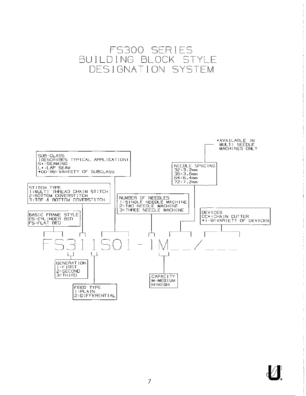
FS300
SERIES
BUILDING
BLOCK
DESIGNATION SYSTEM
SUB-CLASS
I DESCRIBES TYPICAL APPLICATION!
S•cSEAMING
L•
-LAP
•00-99=VAHIETY
STITCH
JoMULTI
Z=BOTTOM
3=TOP & BOTTOM
BASIC
CS=CYLINOER
FS=FLAT
I I r I I I I
SEAM
TYPE
THHI::AD
COVERSTITCH
BED
STYLE
BED
FRAME
OF
SUBCLASS
CHAIN
COVERSTJrCH
--
STITCH
NUMBER
1
=SINGLE
Z=TWO
3=THREE
NEEDLE
OF-
NEEDLES
NEEDLE
NEECLE
MACHINE
Nl::LDLE
32=3.2
36=3.6
64=6.4
72=1.2
MACHINE
MACHINE
I
STYLE
mm
mm
mm
mm
DEVICES
CC~=CHA!N
•I-9=VARIETY
~-----,
•AVAILABLE
MULTI
MACHINES
NEEDLE
CUTTER
OF
IN
ONLY
DEVICES
FS3
( l
CG:CE=:Nc;Ec;cRA
!=f-IRST
Z=SECOND
3=TH
l_cRo_D
1 1 SO 1
T 1
ON
_
_j
FEED TYPE
!=PLAIN
Z=OJFFER~NTJAL
lM
CAPACITY
M=MEDIUM
H=HIGH
7
__
/
__
Page 8

CAUTION AREAS:
8
,
BELT
'
IN
['
__________
GUARD
PLACE
,
•
_j
Page 9
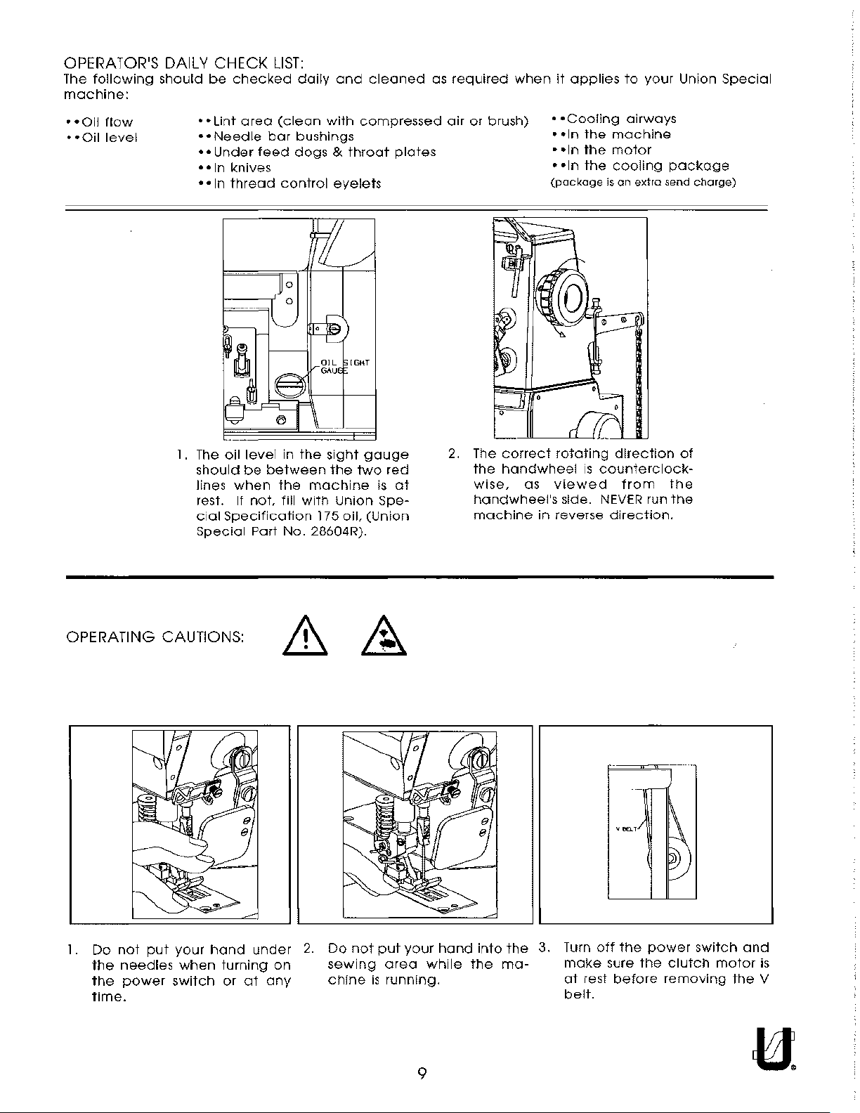
OPERATOR'S DAILY CHECK
The
following
machine:
•
•Oil
flow
•
•Oil
level
should
1.
be
checked
•
•Lint
area
• •
Needle
• •
Under
•
•In
knives
•
•In
thread
The
oil
should
lines
when
rest. If
cial
Specification
Special
feed
level
be
not,
Part
LIST:
daily
(clean
bar
bushings
dogs & throat
control
in
the
between
the
machine
fill
with
175
No.
28604R).
and
with
compressed
eyelets
sight
the
two
Union
oil,
cleaned
plates
gauge
red
is
at
Spe-
(Union
as
required
air
2.
when
or
brush)
The
correct
the
handwheel
wise,
handwheel's
machine
as
it
• •
•
•In
•
•In
•
•In
(package
rotating
viewed
side.
in
reverse
applies
Cooling
the
the
the
is
is
counterclock-
NEVER
direction.
to
your
airways
machine
motor
cooling
on
extra
direction
from
run
Union
package
send
charge)
of
the
the
Special
OPERATING CAUTIONS:
1.
Do
not
put
your
hand
the
the
time.
needles
power
when
switch
turning
or
under
at
on
any
2.
Do
not
sewing
chine
put
area
is
running.
your
hand
while
into
the
the
ma-
3.
Turn
make
at
rest
belt.
off
sure
before
the
I~
power
the
switch
clutch
removing
motor
and
the
is
V
9
Page 10

OPERATING CAUTIONS
4.
5.
6.
During
motor.
Do
that
Before
switch.
OFF
machine
operation,
not
operate
have
inspecting,
Make
the
power
been
to
your
provided.
sure
switch.
rotate
do
adjusting,
the
abruptly.
(CONT.):
not
allow
machine
Doing
flywheel
DO
NOT
head,
without
so
cleaning,
on
the
depress
hands
the
proper
is
very
threading
motor
the
or
any
instrument
belt
dangerous.
the
has
stopped,
foot
pedal
guard,
head
while
it
or
will
the
tool
etc.
sewing
replacing
be
kept
machine
near
guards
needles.
running
is
running
handwheel, V belt
or
any
other
protectors
turn
OFF
the
power
by
inertia
or
it
after
will
turning
cause
and
the
7. Turn
8.
Do
OFF
not
wipe
OPERATING
the
THE
power
the
machine
PEDALS:
switch
when
surface
you
with
leave
lacquer
DDQ
your
machine
thinner.
Q
or
in
case
of a power
failure.
1.
Locate
needles
2.
Locate
3 Use
to
the
presser
S-shaped
presser
center
hook
lifting
lifter
lever
of
pedal
(C)
(E).
drive
to
connect
treadle
(B)
for
(A)
operator
presser
to
be
comfort.
lifter
10
in
line
pedal
with
chain
the
(D)
Page 11
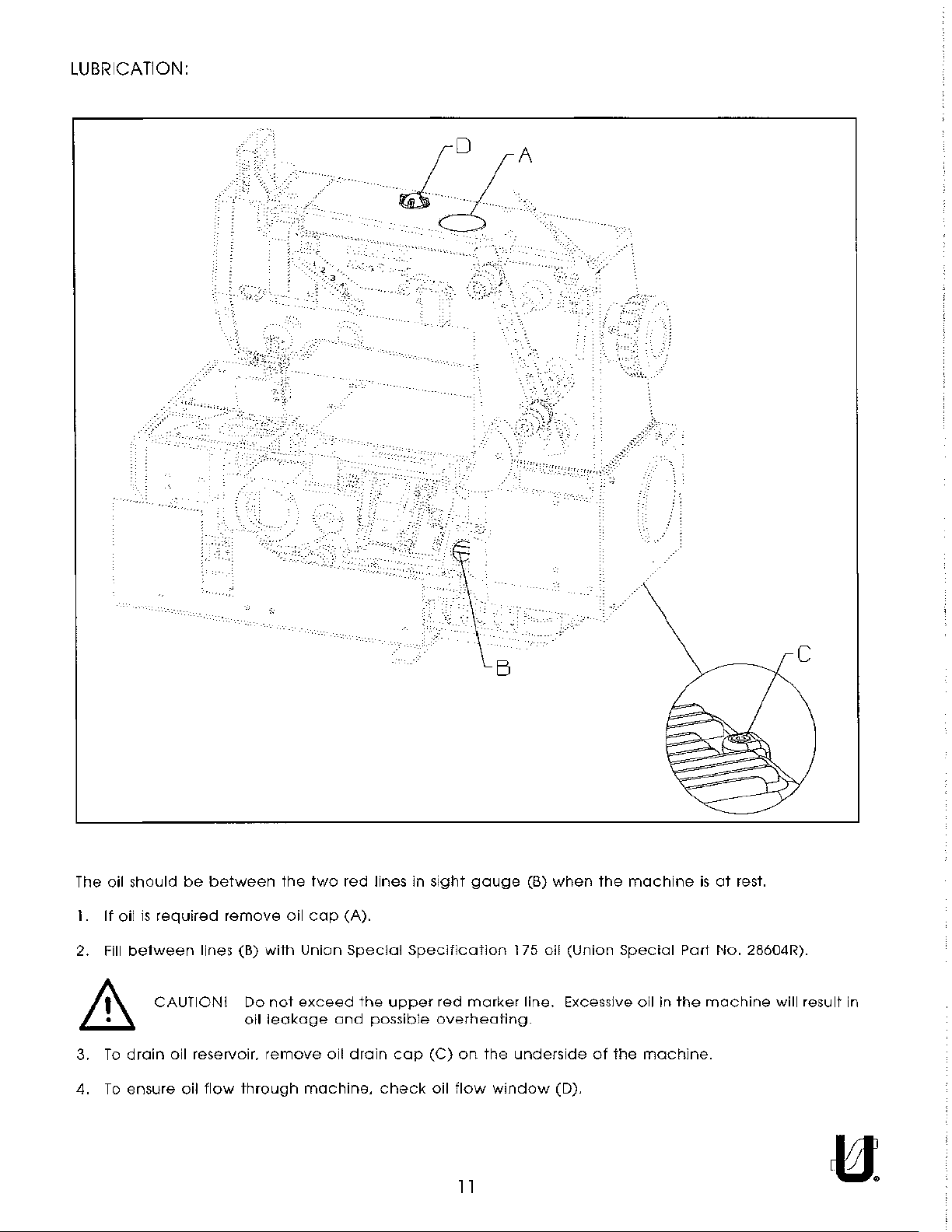
LUBRICATION:
--~,
--
--
The oil should
I.
If
oil
is
required
2.
Fill
between
CAUTION! Do
be
between
lines (B)
the
remove oil
with
not
oil
leakage
two
cap
Union
exceed
and
'.
'"--
red
lines in
(A).
Special
the
possible
sight
Specification
upper
red
overheating.
B
gauge
marker
_:
,,
__
---
(B)
when
the
machine
175 oil
(Union
Special
line. Excessive oil in
Part
the
is
at
rest.
No.
machine
c
28604R).
will result in
3.
To
drain
4.
To
ensure
oil reservoir.
oil
flow
remove
through
oil
drain
machine,
cap
check
(C)
oil
on
flow
the
underside
window
(D).
ll
of
the
machine.
Page 12
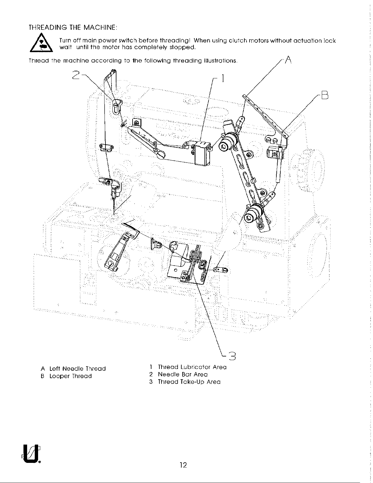
THREADING
THE
MACHINE:
~
~
Thread
the
Turn
off
walt
machine
2
main
until
power
the
motor
according
switch
has
to
the
before
completely
threading!
following
stopped.
threading
When
using
illustrations.
1
clutch
motors
without
A
actuation
lock
B
A
B
Left
Needle
Looper
Thread
Thread
1
Thread
2
3
Thread
Needle
Lubricator
Bar
Area
Take-Up
Area
Area
3
---
..
,.,
..
'-.--
12
Page 13
THREADING
~"'
l..lrA
THE
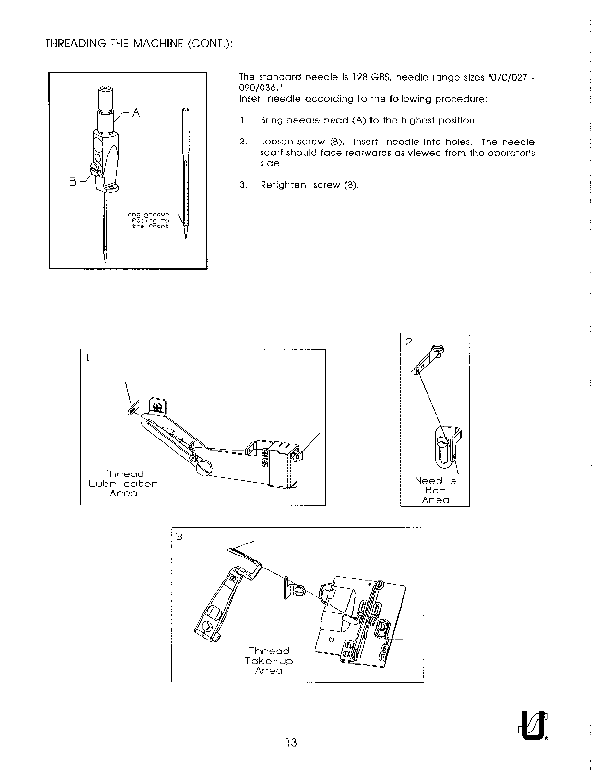
MACHINE (CONT.):
The
standard
090/036."
Insert
needle
1.
Bring
needle
according
needle
head
is
128
to
(A)
GBS,
the
to
needle
following
the
highest
range
sizes
procedure:
position.
"070/027-
B
""
If
Long
groove
rocong
the
r.-ont
to
2. Loosen
scarf
side.
3.
Retighten
\
screw
should
(B), insert
face
screw
rearwards
(B).
needle
as
viewed
into
holes
from
The
the
operator's
needle
Thread
Lubricator
Area
Needle
Bar
Area
3
Thread
Take··up
Area
13
Page 14
THREADING
THE
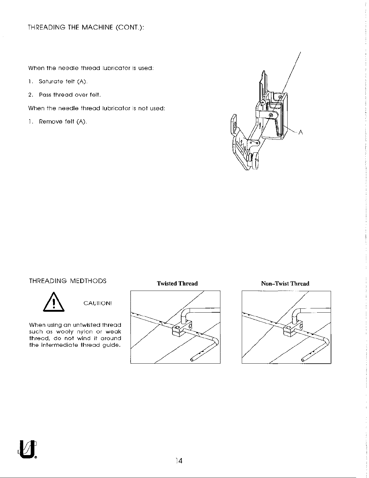
MACHINE (CONT.):
When
1.
Saturate
2.
Pass
When
1.
Remove
the
thread
the
needle
felt
needle
felt
thread
(A)
over
thread
(A).
felt.
lubricator
lubricator
is
used.
is
not
used:
A
THREADING MEDTHODS
CAUTION!
When
such
thread,
the
using
an
as
wooly
do
not
intermediate
untwisted
nylon
wind
it
thread
thread
or
around
guide.
weak
Twisted Thread
Non-Twist Thread
14
Page 15
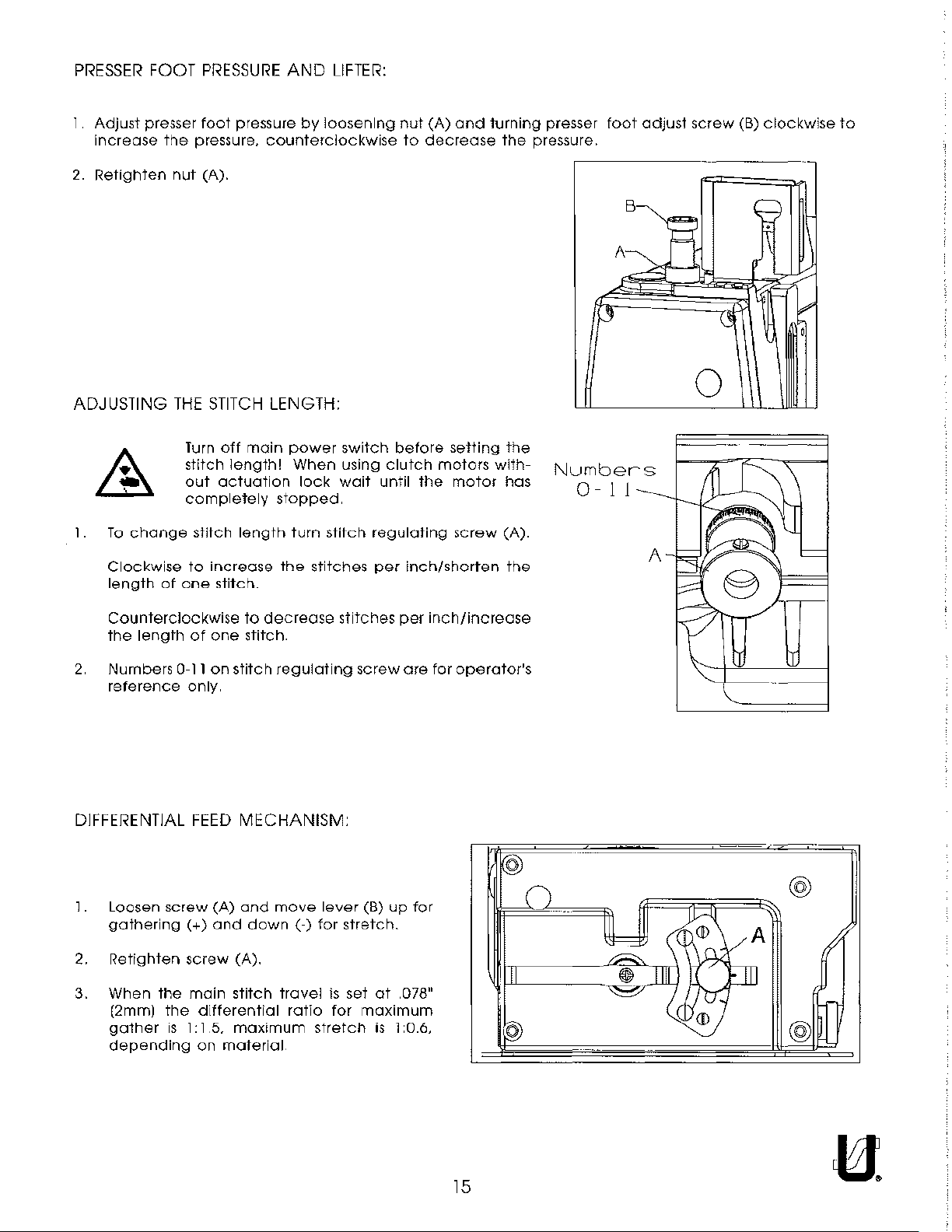
PRESSER
FOOT
PRESSURE
AND
LIFTER:
Adjust
Increase
2.
Retighten
presser
ADJUSTING
1.
To
change
Clockwise
length
foot
the
pressure,
nut
(A).
THE
Turn
stitch
out
completely
stitch
to
of
one
pressure
STITCH
off
main
length!
actuation
length
increase
stitch.
by
loosening
counterclockwise
LENGTH:
power
When
stopped.
turn
the
lock
stitch
stitches
switch
using
wait
regulating
until
per
nut
(A)
to
decrease
before
clutch
motors
the
inch/shorten
and
setting
motor
screw
turning
the
the
with-
has
(A).
the
presser
pressure.
Numbers
0-
foot
A~
f3
1 1
adjust
B
A
H
H
screw
--
~
0
(B)
clockwise
~
.
::§
to
~
Counterclockwise
the
length
2.
Numbers
reference
0-11
DIFFERENTIAL
1.
Loosen
gathering(+)
2.
Retighten
3.
When
(2mm)
gather
depending
screw
the
the
is
of
one
on
stitch
only.
FEED
(A)
and
screw
1: 1 5.
(A).
main
stitch
differential
maximum
on
material
to
decrease stitches
stitch.
regulating
MECHANISM:
and
move
down(-)
travel
ratio
lever
for
is
for
stretch
screw
(B)
stretch.
set
at
maximum
is
per
inch/increase
are
for
up
for
.078"
1 :0.6,
operator's
(2J
_o_
II
II
~
-·
l=,
--=
'='
·-
®_
--
~
1111
({;l"'tr:
~
cH<
JD
@
A
I
@
15
Page 16

.
·14· · ...
.
15
'
13
~-'---'
···········o
/
·~···
. .
.·
..
~·
16
Page 17
BUSHINGS
Ref.
No.
Part No.
50654
1.
2. 50332U
50330CZ
3.
50654A
4.
50344BE
5.
SQ1110401MZ
6.
50344BC
7.
50344E
8.
50344BF
9.
350368$
10.
11
. 50393GE
12. 22571L
13. 50393FU
14. 50393EY
15. 50392AB
PS0400142KH
16.
50381E
17.
18. 50344BU
SQlll
19.
0401
Description
Bushing,
Pin,
Bushing,
Bushing,
Bushing,
Bushing.
Bushing ...
Bushing,
Stitch
Oil
Screw,
Fitting,
Fitting,
Bushing,
Pin .... ... ... ............ . ......... .
Bushing,
Bushing,
MZ
for
needle
for
front
lifter
for
presser
for
needle
for
lower
Fitting ........... . . ........
for
needle
..
. . . .....
for
lower
Regulator
Sight
Gauge
for
drain
oil
tube
filter
...........
for
tension
for
lifter
front
Fitting ...........
bar,
lever
bar..........
bar,
mainshaft.
lever
..
.......
mainshaft,
Bushing . . ......... .
. . . . . ............ . .......... .
plug
..
...... .
.
lever,
... .
..
. . ... . ..........
..
............... ........
upper
......... .
lower
left
..
. .......... .
..........
.. .. . ..
.....
right
release
back
.. .
...............
.
.
......................
. ........... ............
..
....... . .
..
... .
.............................................
.
...........
..
... . ........... .
.....................................
..
. . .... .... . .......... .
.................................
..
.......... .
..
..
................................
Amt.
Req.
1
.
1
1
.
1
1
.
.
1
1
1
1
1
1
1
1
1
1
1
.
1
17
Page 18
I
2
.;o!~'
,,,
3
TORQUE"
18-20i.:..
IZ.0-2.3N~f·
'
,,
I
4
21
22
12
ln.
.0-2.CJNmi
lbs
'
'
9
'
:
'
'
'
un1onL~ct•tel
N
0
pecn
•
1
CE27
1
18
Page 19
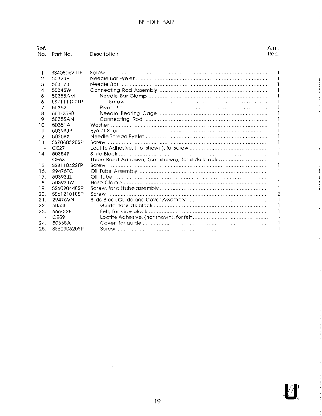
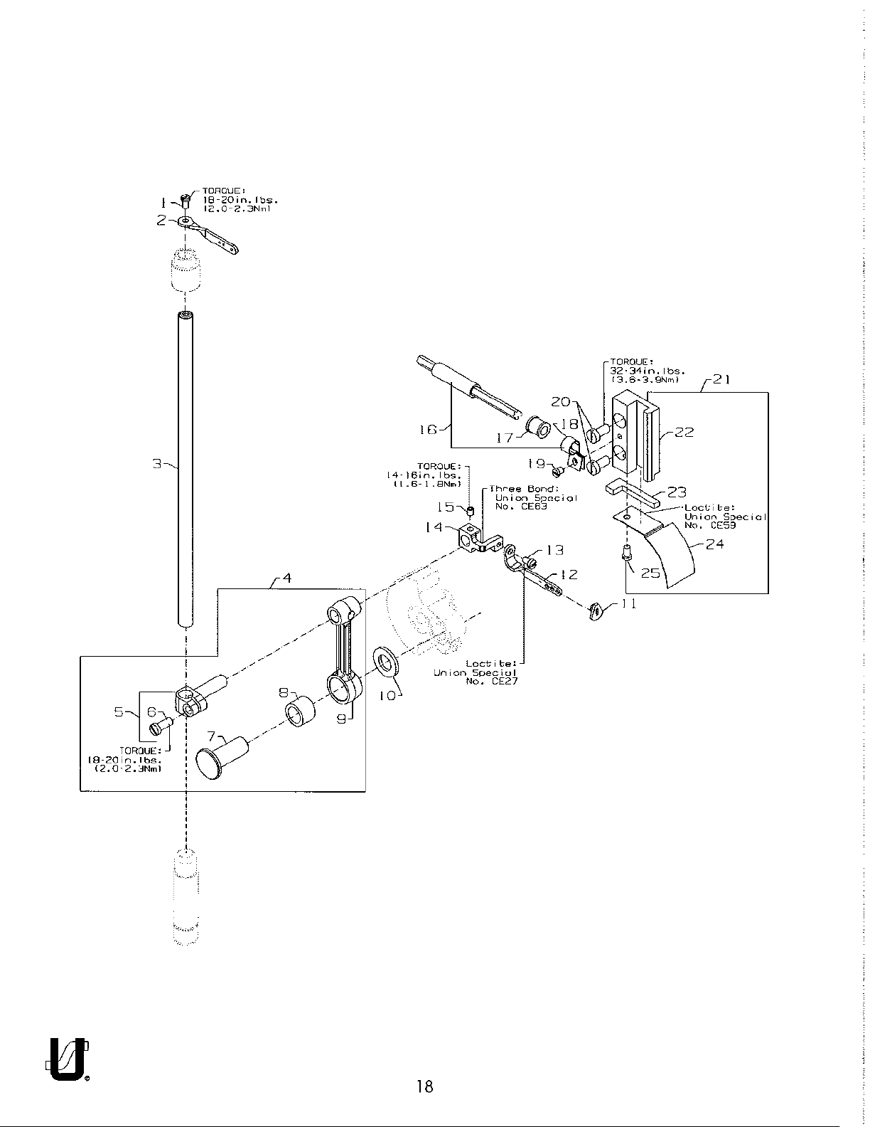
NEEDLE
BAR
Ref.
No.
Part
No.
SS4080620TP
1 .
2.
50323P
3. 50317B
4.
50345W
5.
50355AM
SS7111120TP
6.
7. 50352
661-2598
8.
50355AN
9.
10. 50351 A
50393JP
11.
12. 50358X
SS7080520SP
13.
CE27
14. 50354F
CE63
SS811
15.
16.
17.
0422TP
29476TC
50393JZ
18. 50393JW
19. SS6090440SP
SS6121010SP
20.
21. 29476VN
22. 50338
666-328
23.
CE59
24
50338A
25
SS6090620SP
Description
Screw.
Needle
Needle
Connecting
Washer
Eyelet
Needle
Screw
Loctite
Slide
Three
Screw
Oil
Oil
Hose
Screw,
Screw
Slide
Bar
Bar . ...... ........ ..
Needle
Screw
Pivot
Needle
Connecting
...... .
Seal ... .
Thread
............. .
Adhesive.
Block
Bond
... ....... . . .......
Tube
Assembly
Tube
Clamp
for
Block
Guide,
Felt,
for
Loctite
Cover.
Screw
.
................................................................................
Eyelet
Rod
Assembly
Bar
Clamp
...... .....
Pin . .......... ................ ...
Bearing
............. ............... ......
Adhesive.
......
oil
tube
............ . ........... . ......... .
Guide
for
slide
slide
Adhesive.
for
......
Cage
Rod
Eyelet.
(not
. .
assembly.
and
block
block.
guide
........... .
....................................
. ............ ............. ....
.... . ........... ....... ..... .
..
...............................
..
..........
............................................
shown),
(not
Cover
(not
..
for
screw
....................
..
.......................
shown),
Assembly
........... ............ .. ............
shown),
.............. .
......................
for
slide
..
........
............
............
..
.....................
.......................
for
..
........................
felt.
..
block
..
........................
........................
..
.............. .
..............
..
.......... .
.........................
.
..
...
..
..
..
..
. ......... .
..
..
..
..
..........
.
Amt.
Req
.
.
..
.......... .
.
..
.
.
l
I
I
2
19
Page 20
TORQUE:
54·56in.lbs.
~-t--
3
TORQUE:
46·48in.lbs.
15.Z-5.4Nml
'
'
\
'
'
'
'
'
\,
16.0-6.3Nml
I I
TORQUE:
32-34in.
13,6·3.9Nml
lbs,
13
12
' '
/ '
' '
32-34in.lbs,
13.6-3.9Nml
'
'
'
'
'
'
'
'
'
'
'
'
4
/~/':OROUE'
_..
~
~
TORQUE:
5'1-~6in.lbs.
16.0-6.3Nml
'f6·18•n.
15.2
2
lbs.
5.4Nml
20
Page 21

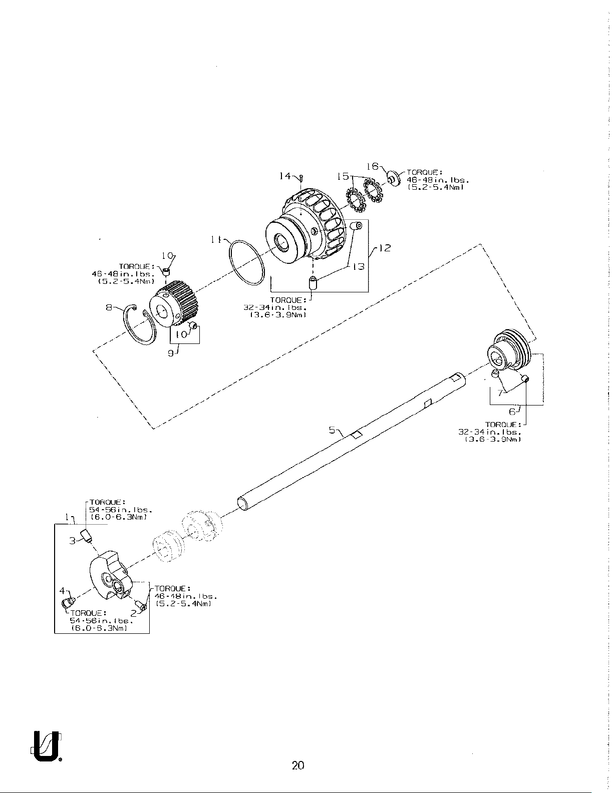
UPPER
MAIN
SHAFT
Ref
No.
Part
No.
1
50391
2.
SS7llll20TP
3. SS8681412TP
4. SS7681410TP
50322AF
5.
6. 50335BD
SS8660612TP
7.
661-262
8.
9 50342BE
SS8661 0 12TP
10.
660-1087
11
12 50321F
SS8681412TP
13
660-1043
14.
661-261
15.
SS7660520SP
16.
Description
Counter
Upper
Bearing
Weight
Screw,
Screw,
Screw,
Main
Adapter
Screw,
Retaining
Sprocket,
Set
Screw,
"0"
Ring.. ........
Handwheel
Set Screw,
Tack
Pin,
Load
Ring,
Screw,
for
for
counter
for
counter
for
counterweight
Shaft
for
bearing
Ring
.................................
for
upper
for
.. ..
for
for
handwheel
for
lower
handwheelpreload
weight
weight.
Assembly
adapter
main
sprocket
..
...... .
...................
handwheel
main
shaft
shaft
.................
................ .
.................
..
.
........
.
..............
................
.. ..
.. .
....
..
.
..................
.......
Amt.
Req.
..
1
1
..
.
..
.
.
..
.
..
........
..
1
2
1
1
2
1
1
2
1
2
1
21
Page 22

------
------
____
.-
-----
_____
_
._,--
--~
------
-----
-----·
------
------
---------
9
---
-~--
24'
?-~.
-='--
.
19
"'-
'«·
-------------
•.
·
20
~
-----
..
·
-----
------
-------
------
---
-----
---
22
Page 23

THREAD GUIDE
Ref.
No.
Part
No.
1.
SS7120640SP
2.
50692H
SS709091
3.
WS041 0002KP
4.
5.
50366A
50392S
6.
7.
50366
SS4120915SP
8.
29476TG
9.
50393HH
10.
11
50683A
OTP
12 SS4090815SP
13
563588
14.
56358C
15.
1588
563580
16.
17.
98A
18.
22837
19.
12124202
20.
SS70906105SP
21.
SS7120640SP
22.
50392AE
23. SS1121010SP
24. 50357AR
SD0380551
25.
26.
50357AS
27.
50357Y
50366G
28.
29.
50357V
30.
605A
31.
C50044E
SS7120710SP
32.
50663
33.
Description
Screw.
Thread
Screw,
Thread
Looper
Screw
Screw
Looper
Screw,
Nipper
Sl
Screw,
Needle
Screw,
Needle
tor
Eyelet
Screw
Split
Washer
Thread
Lead-In
Thread
for
Ratio
Silicone
Thread
Screw,
Guide
Guide
Thread
Washer
Screw
Screw
Frame
................
Frame
for
Plate
Screw
Nipper
Nipper
Thread
Nipper
for
Thread
for
Thread
lead-in
Assembly
................
Eyelet
spreader
Control
Block
........... .
.......... .
Spring
Spring
Plate
needle
strike-off
Tube
Tension
Eyelet
Control
Thread
for
silicone
Eyelet
........... .
............. .
Eyelet
Eyelet
thread
Assembly
...... .
Plate
Guide
........ .
Guide
Strike-Off
Bracket
.
.
.... . ......... .
eylet
.
Bracket
Eyelet
Tube
thread
Assembly
Lubricator
tank
... .......... ............... .
guide
.
thread
............
.....
Eyelet
...
.
...... .
guide
......................
guide
.
..
..
.
....
.
........
Amt.
Req
2
1
1
1
1
1
1
2
1
1
1
2
.
1
1
1
1
1
1
1
1
1
2
1
1
1
23
Page 24

~--~~-
20
22
TOROUF:
0
14"15in.lbs.
I 1
.6·
1.8Nrnl
~rm:'j
----·
-----·
'-, l
'
---
[.--
<
---'-
------
--~--
------
·---
3
_-
-,_
-------
'---·
---
24
Page 25

TENSION
RELEASE
& THREAD TENSION
Ref.
No.
Port
No.
I.
50392Z
660-283A
2.
3. SS4120915SP
4 50692B
5. 57892K
6
56392G
7.
B3120352000
666-330
8. B3126012000
9. B3120704000
10. 56392H
11. 11550209
B3103804000
B3121804000
12. B3112704000
13
50692G
56392R
14.
50392W
15.
50392AV
16. SS7090520SP
17. 50392X
18. 57865
19.
NS6ll
0420SP
20. 50392BC
21. 22875N
22. SS7121410TP
Description
Tension
Retainer
Screw,
Two
Tension
Needle
Washer
for
tension
Thread
Thread
Tension Post
Tension Disc Felt
Disc Felt
Tension
Tension Disc Felt
Spring
Spring,
Spring,
Spring,
Ferrule,
Knob.
Knob,
Tension Disc
Guide,
Screw.
Tension
Lead-In
Nut
Stop
Binder
Shield
needle
looper
Release
Screw
Lever
........... .
assembly
Tension
Tension
Disc.
needle
spreader
looper(plain)
tension
for
for
Brocket
Thread
Screw
Assembly
Eyelet
......
(green)
(blue)
spring
(green)
(plain)
Separator.
tension
guide....
disc
..............
Guide
Lever
Shaft
...
.............................
Assembly
.
..........
...
..............................................
.........
....
separator
..
.
.
..
......
..
.
Connection
..
..
..........................
.......... .
.........
..
Amt.
Req.
1
1
2
1
2
2
2
4
4
2
2
3
1
,
..
1
2
3
1
1
2
2
1
2
2
25
Page 26

22
4
I
I
5
/
c
I
I
I
'
I/
8
!
!
l
"
"
'-
20
I
un;on
18
t.oct;te:
Spoc;ol
No.
17
CE66
ooe,,,,
n1on
Specool
o.
CEBB
16
~
15
'i,
f
14
26
Page 27

PRESSER
FOOT
LIFT
Ref.
No.
Part
No.
l.
11071602
11071701
2.
660-1014
3.
4. C50056B
5.
50357AA
50357AP
6. C50056J
7. 506438
B.
50335AF
50643A
9. SS6110610TP
10.
50335AG
11. 50335AH
12
SS811
0422TP
660-739
13.
14.
REOSOOOOOKO
15. 50381F
16. SD0790303SP
CE49
17. 29476TK
18. SD0790303SP
19. 50355AR
20. 50381 G
21. SS9151740CP
22. 29476TT
SS6151920SP
23.
24. NS6150310SP
25.
50332V
26. SS6153040SP
SSL1121215SP
27.
CE49
28. 50381
29. R0068190100
30. 50381B
Description
Adjusting
Locking
"0"
Ring
Spring
Spring.
Spring.
Lock
Screw
Presser Bar, for SOl, S02
Pressr
Screw,
Guide
Presser
Set
Oil Seal
E Ring,
Lever,
Screw,
Loctite
Rear
Screw,
Wire
Stop
Screw,
Stopper,
Screw,
Screw,
Loctite
Spring,
"0"
Lifter
Screw.
Nut
..........................
Rod
.... .... .......... .
for
presser
for
presser
Nut.
.........................
Bar
.........
for
guide
Plate,
for
Adhesive,
Lifter
Lifter
Assembly
Hex
Ring
Lever
for
Bar
Guide
Screw
for
Hex
for
Adhesive,
for
........... ... ............. ..... ....... ............ . .........
..
................. ..
for
pin
lifter,
wire
Lever
for
lifter
Connector
lever,
Screw
for
adjusting
Nut
..................
for
for
adjusting
stopper
lifter
..............................
Assembly
for
bar,
bar.
..
plate
presser
..............
........ ..
front
connector
(not
Assembly
lever
....... . ....
rear
.
lifter
............ .
(not
lever
spring
........... .
............
........... .
.
for
SOl.
for
differential
..
machine
......
bar
... .
shown),
.....
assembly..
stopper
..
lever
......
stopper.......
shown),
.......... .
..
..
...................
S02
machine
styles.
..
.........
..
.................................................
..
..
........... .... ....... . ...........
for
screw
...........
..
.........
.. ..
for
screw
feed
..
..............
........
. ........
..
styles
machines
.....................
........................
..
.................
.
..
..... .........
..
..
..
..
..
..
..........
.....
..
...
..
..........
..
....................
Amt.
Req.
1
1
1
1
1
1
1
1
2
1
1
..
2
1
1
..
1
..
1
..
1
..
1
..
1
1
1
1
1
2
1
1
2
27
Page 28

Jij
'
'
'
'
'
'
-
__
,
'
18
22
28
Page 29

COVERS,
UPPER
ARM
Ref.
Part No.
No.
SS4121615SP
1.
2. 50393EU
3. B3530555000
660-212
4.
50382FW
5.
6. 50382FZ
7. SS7120640SP
50317C
8.
T A 1
9
10
050504RO
50393HB
11. 50384L
12.
50382GB
SS4120915SP
13.
14. 50382FY
15. 50382FX
16. SS4121215SP
17. T A
18.
19.
20.
21.
22.
23.
11
00604RO
99682XCB
NS6620320SP
50383AE
50383AD
99682XC
SSlll0640SL
24. SD0640323TP
25. WZ064151
26.
22517B
652Cl6
27.
28.
50393EW
29. 50696
SS4120915SP
30.
SS4
1 206 I
31.
32.
50382GM
SSP
33 SS4120615SP
34 LA452
OKP
Description
Screw,
Plug,
Oil Sight
"0"
Top
Quad
Screw,
Needle
Plug,
Plug,
Gasket.
Puller Drive
Screw,
Quad
Head
Screw,
Plug,
Protection
Screw
Washer
Rubber
Cover,
Screw,
Screw.
Thread
Screw,
LabeL
for
for
top
Gauge,
Ring,
Cover
Ring,
for
Bar
for
for
for
for
Ring,
Cover
for
for
head
Nut
................................
Bracket
Bracket
Protection
Counter
Shoulder
Spring
......... .
Gasket
for
for
for
Cover
for
direction
top
cover.
cover
for
..................... .
for
needle
bed
bed
puller
Cover
puller
for
head
Shield Assembly
Washer
thread
thread
thread
thread
............... .
top
.............. .
all
sight
gauge
top
cover
bar
Guard
................... .
............................ .
drive
. ..... . .............. .
drive
head
........ .
cover
cover
Holder
......................... .
Shield . . ............ .
Sunk
Head
Screw
............
for
needle
take-up
take-up
cover
... ..........
take-up
of
rotation
......... .
guard
...........
cover
cover
cover
.............. .
........
..
.
...... .
..
Screw
,.,,,,,,,.,,,,,,,,,,,,,,,,.
lever
cover.
..
.....................
cover
......... .
..............
..... .
.
..................... .
............. .
.........
.
......... .
.
...... .
.
.
Amt.
Req.
6
1
1
2
1
1
2
1
1
4
1
1
4
1
1
1
1
1
1
2
1
.
29
Page 30

TORGUE'
46-48in.lbS.
15-2-5-~'":·~·~~o-~-'--,
<
'
(-
9~//,'-'
/
'
' <
<
<
'
'-,'.,
10
' <
'
'
',
,',
18
30
17A
Page 31

LOWER
MAl
N SHAFT
Ref.
No. Part No.
1 SS7660520SP
660-1062
2
50374
3.
50321 G
4.
SS8661012TP
5.
50342AX
6.
SS8660612TP
7.
50342BS
8.
50335AK
9.
10. 29476UH
11. 50322AL
12. 50335BB
13.
50322AG
50333A
14.
SS8660612TP
15.
660-934
16.
17.
506220
17A. 50622E
18. SS8660410SP
Description
Shoulder Screw,
Spring Washer
Spacer.
Pulley
Sprocket.
Timing Belt ....
Retaining
Mainshaft
Coupling,
Oil
Lower
Lower
for
pulley
Assembly ........
Set
Screw...
for
lower
Screw
Ring,
Assembly,
Ball Bearing,
Retaining
Lower
Screw
seal
Main
Main
Screw
Ring
Main
for
lower
... .............
............... .
Shaft,
Shaft,
....................................................................................
for
lower
main
shaft,
right..
.....................................................................
assembly
..
.
.............................
main
..
...................
for
ball
bearing
lower.
for
lower
....................................
Shaft,
right
main
..
left
for
left
for
...
........
shaft
... ......... .
.... ...... ...
right..
main
...... .
shafts .......... .
........
plain
differential
.... ...... ...
shaft
..
............
feed
...
..........................................
..........
.
.
feed
. .......... .
..
.......... .
..
................ .
.
...............
..
......................
..
......... . ....................... .
..
.......
.
.
..
..........
Amt.
Req.
.
I
I
2
..
1
2
.
1
1
..
1
1
1
1
1
4
1
1
1
..
2
31
Page 32

CONNECT
50393BU
0
,------_L__23
14
'
d
'I
--'·
/I
( I
I ,
I
I
I
-32
I
[;14'
I
26
'
25
<,_
27
TO:
OIL
CONNFCTOR
PUMP
IBI
50393HN
TO: CONNECTDn IAI
OIL
'
-/
_/
'>ff"""'~
OF
PUMP
50393HN
CONNECTOR
PUMP
50393HN
ICI
OF
OF
/////44
(
'
I
38Q
TO: SUCTION
[MOUNTS
TO
OIL
LOWER
TUBE
50:93H~
BED
CASTINGI
32
Page 33

LUBRICATION, OIL TUBING & OIL PUMP
Ref.
No.
Part
No.
50393HN
1.
SS8660612TP
2.
503325
3.
4.
34393D
5. 50393EX
6. SS86606 l
7.
50393GB
8.
50393GD
2TP
9. SS4091015SP
10. 50393FR
50384
11.
11843208
12.
50393FV
13.
14. 29476US
15. SS7120710SP
16.
NS6ll
0310SP
SQlll0402MZ
17.
50393KH
18.
50393-27
19.
20. 50393KM
50393-447
21.
50393-140
22.
23 29476UT
24. 50393KH
50393-70
25.
50393KM
26.
27 13765607
50393-140
28.
50393-40
29.
50393-170
30.
50393KF
31.
32. 50393KM
33. 50393HR
34. 50393HL
50393FS
35.
36. 998-358F
37. SS4090815SP
38. 50393HK
39. SS6151812TP
40. WS063151
41. 22571E
42. RM2871 B
43. 50393EB
44.
50384A
50393FT
45.
46. 50393HJ
Description
Oil
Pump
Assembly,
Screw
Spring,
Plunger
Collar,
Screw
Oil
Pump
Oil
Pump
Screw,
Cover.
"0"
Oil
Oil Tube.
Oil
Oil
Oil
Plastic
Screw,
Felt ........................... .
Screw,
OKP
Spring
Screw,
Cable
Oil
"0"
Oil Tube.
Oil Tube,
for
for
Ring, for oil
Filter
..
Supply
Screw,
Nut
.................................. .
Fitting
Tube
Retaining.
Oil
Tube
Tube
Retaining,
Oil
Tube
Oil
Tube
Supply
Tube
Retaining,
Oil
Tube..............
Tube
Retaining,
"T"
Connector
Oil
Tube
Oil
Tube
Oil
Tube
Oil
Tube
Tube
Retaining,
Plug,
for
Oil Tube,
Tube
Holder
Clip
for
for
Washer
for
Tie.......
Pan
........... .
Ring .........
for
for
2-stage
for
plunger
...................... ,,,,,, ...... .
for
oil
Housing, 2 Stage
Housing, 2
oil
filter
oil
filter.....
for
supply
Assembly.
for
front
.................
................
...........................
Assembly,
feed
for
oil
tube
oil
pan
.........................................
oil
drain
suction
suction
................
pump
.............................
filter
chamber
suction
.......
..
..
Stage
cover.
(1)
upper
upper
spring
spring
lower
spring
spring.
..........................
spring
holder
....................................
plug
.................................
.....
.............. .
. ............. .
cover
.... .
.....
....
tube.
..
...............
..
....... .
.......................................
...........
..
...........
..
...........
.
.
.....
..
.......... .
.............................
..
..
..
..
.
..
.
..
.
Amt.
Req.
1
2
2
2
1
2
1
1
3
1
1
1
1
1
2
.
1
1
1
1
3
1
1
..
1
2
1
5
2
1
1
1
1
3
1
1
1
1
1
1
6
6
1
2
1
1
1
1
33
Page 34

13
Copped
Is
28-30in.lbs.
TORQUE:
[3.2·3.4Nml
32-34~n.lbs.
(3.6-3.9Nml
15
NOTE:
End
Down
8
34
Page 35

LOOPER DRIVE
Ref.
No.
Part
No.
50313
1.
2.
22652810
3.
22565
4. 50309F
5. SS7120910SP
CE63
660-893
6.
7.
50344AM
660-455
8.
9.
50313J
10. SS7120910SP
11.
50314F
50314E
12.
50642
13.
14
22653J8
15.
667J33
660-979
16.
17. 50342BJ
SS8660612TP
18.
19. 50342BK
20. SS8660612TP
50342BP
21.
Description
Looper
Looper
Screw,
Three
Oil Seal.
Bearing
"0"
Looper
Screw,
Eccentric
Looper
Looper
Sprocket.
Sprocket.
Looper
Holder
Screw,
Screw,
forbearing
Bond
looper.......
Housing
Ring,
Rocker
for
Avoid
Drive
Screw
Crank
"0"
Ring
Screw
Screw
Drive Belt
...
for
looper
for
looper
Adhesive,
for
bearing
retaining
Retaining
Adjusting
Assembly
Pin............
for
looper
..... ........... . ............ .
for
looper
......
holder.
holder
housing
(not
Assembly,
housing
Assembly
plate...
Plate
.........
driven
drive.
..
........
..
.......... ..
shown),
for
.
..............
Eccentric
..
................
... .
........................... .
for
............
looper
assembly
..
.......
..
.
.............
..
.........
..
..........
..
. ........ , ,
screw
drive.
..
..............
.........
..............
...............
..
..................
....
.
..
..
,.. ... , , .......... .
..
.........
..
..
..
.
..
.......... ..
Amt.
Req.
1
1
3
1
1
1
2
1
1
1
1
1
2
1
2
1
2
1
35
Page 36

4
36
Page 37

NEEDLE
GUARD
Ref.
Part No.
No.
1.
29476UJ
2.
50373DA
3. SS8110422TP
4.
50368W
5. 50368T
6 SS8110422TP
7 50368E
8
50368A
9.
50368V
10.
50354l
11.
SS8ll0422TP
12. 50325AF
13. 50325AE
14.
SS9090420TP
Description
Rear
Needle
Needle
Screw.
Connecting
Pivot
Link . ............
Screw
Washer .
Pivot
Shaft,
Coupling,
Screw
Holder.
Needle
Screw,
for
needle
for
Guard.
for
Guard
Guard
for
Rod Assembly,
Pin
for
needle
needle
rear
rear
needle
Drive
Eccentric
needle
guard
guard
................
guard
........
Assembly
...
guard
..
......................
...................................
...............
...... .
.
..
guard
..................
eccentric
for
needle
..
.
..
............
....... .
guard
Amt.
Req.
.
.
1
1
2
1
.
1
2
2
..
1
1
1
2
1
1
1
37
Page 38

18
~17
i
i
\
I
i
.
i
l I
\ \
\ \
I I
'
i
~
\"---...__
-...._,_
-.
14
15
ilJ2~~----------
-~--r>,.?>./23
L_
____
--':_;;2';..'2_:'
24
30
38
Page 39

LOOPER THREAD TAKE-UP
Ref.
No.
Port
No.
1 50657
2.
51959D
3 51959K
4. 51959L
5. 519598
6. 51492
7. 52958D
8. SS7060310SP
9. 50304H
10. SS9080410SP
11. 41358
12. 50304L
13. SS7080520SP
50383E
14.
15.
50357W
16.
SS9111 0 lOSP
17.
SS61
1061
OTP
18.
29476UK
19. SS709211
OTP
20. 50383F
21. 50304K
22. WZ0640200KP
23
SD0630275SP
24
50623
25
22894C
26.
503238
22-348
27.
28 50377R
29. 50323H
30.
778
Description
Cast-Off
Screw,
Screw,
Cast-Off
Take-up
Plate
Knurled
Tension
Pin ......................
Roll
Tension Disc
Tension Post ......
Toke-up
Screw
Strike-Off
Screw
Washer
Retaining
Screw
Mounting
Cast-Off
Screw,
Take-up
Cast-Off
Washer
Shoulder
Set
Take-up
Spacer
Disc,
Screw,
.........
.................
for
collar
for
cost-off
Plate
for
Assembly
Screw
Pin .
for
for
Assembly
Nut
. .
Spring ................................................. .
Eyelet
.........
Collar
................................................................ .
........
...............
Wire .
Finger
Brocket
Plate
bracket
Holder
collar
Bracket
Plate
Holder
Screw,
.. . .
Hub
..
take-up
take-up
.............................................................
.................................................
..
.........
..
..
..............
..
..........................................
..
........... .
......................................................
..
.
holder
Assembly
bracket....
.....
.. ..
for
cast-off
...
..
....................................
.........................
..
........
..
disc
..
.
.........
..
...........................
..
............................................. .
..
plate
holder
..
, ............
............
.
..........
..
..
..
Amt.
Req.
..
.
1
1
1
1
2
1
3
4
1
1
2
.
1
2
1
1
1
1
1
1
1
l
1
, ...
..
1
l
2
1
2
1
2
2
39
Page 40

"
'
'
'
'
'
-·
··-
'
'
"~~>
--
-~__.1
i
l~r
;>'r·
~\---
..
:
'
'
3-i',~r
'
,,
'
--
;
'
!~~~f~
9
TORGUE:
34
32-.,_...,
J3.u
,n.lbs,
9Nml
"'·
40
Page 41

FEED DRIVE
FOR
PLAIN
MECHANISM
FEED
Ref.
No.
Part
No.
18-1432
1.
2. 50334BD
50334AX
3.
4.
50634
50334A
5.
6.
50634E
22637P24
7.
50640-18
8.
9. SS8660612TP
10. SS7090530SP
11. 50334Y
12.
50334W
13.
50634C
14.
50637A
50335BA
15.
50634D
16.
17. 50637
Description
Screw
..............................
Hex
Eccentric
Drive
Fork
Feed
Bar
Plain
Feed
Feed
Dog
Screw.
Feed
Eccentric.
Screw
Screw
Oil
Shield
Oil
Scraper
Feed
Bar Seal .
Guide
Guide
Feed
Guide
Plate.
Plate,
Bar Seal
Plate.
Stud
Assembly.
Assembly
Bar
Guide
Holder
. ..... ........ .
.
.........................
main
...
left,
rear
right.
..........
front
.
right
..... .
.. .
rear
.
.
.............
.
.
........
.
Amt.
Req.
1
1
1
1
1
.
.
1
1
1
2
10
1
1
1
1
1
1
1
41
Page 42

--
zk-
1~-1@1
.
!
5~,
I
' '
'
I
~-----
',
1
c-
--
---
[3~,,
~:.
0 '
2~
j
i
:
'
'
'
'
>
~~~~-~>
42
Page 43

FEED
DRIVE MECHANISM
FOR
DIFFERENTIAL
FEED
Ref.
No.
Port
No.
18-1432
l.
2. 50334BD
3.
50334AW
4. 50334BE
5.
50334AX
6.
503400
7. SS8660612TP
B.
SS7090530SP
9. 50334Y
I 0.
50334V
11. 50334BH
50335AM
12
13. 50335BA
14 50334J
15.
50335AN
16.
R0681190100
17. 50337J
SS4121215SP
18.
29476UM
19.
20. 50337H
21
50337U
22
50337K
SS7090610SP
23.
24. B1647704000A
25. 50387
SS7090610SP
26.
27. 50337S
28.
SS811
0422TP
29. 50337L
SS6ll
30.
0650TP
31. 50337R
32. SS809071
33.
SS6091
OSP
022TP
34. SP0550271
35.
50337M
36. 50340E
SS8660612TP
37.
TP
Description
Screw
Hex
Drive
Feed
Drive
Feed
Screw
Oil
Oil
Guide
Guide
Guide
"0"
Stem.
Screw,
Screw
Screw.
....................................................................
Eccentric
Fork
Bar
Fork
Eccentric,
Screw
............... .
Shield
Scraper
Feed
Bar Seal ........
Plate.
Plate,
Feed
Bar
Plate,
Ring
for
for
Differential
Differential
Stop
Plate.
Screw
Knob.
Screw
...................
Collar
Coupling,
Collar,
Spring,
Feed
..
..
Screw
Screw
for
Screw
Screw
for
for
Eccentric,
Screw
Stud
....................................................
Assembly
Assembly
Assembly,
.....................
..
left.
right.
Seal
front
differential
stem
Feed
Feed
..............................
for
differential
....
for
differential
..................
for
differential
......................
differential
.....
.......
spring
differential
.......................................
.................
right
...........
main
...................... ,
lever
differential
rear
rear
feed
lever.
.
.......... .
.
..
..........
..........
Assembly
.
feed
feed
lever
feed
feed
feed
..
..
..
lever
lever
lever
lever
....... .
..
..
..
........... .
...........
......... .
....
lever
.................................
.
.
Amt.
Req.
..
.
2
2
I
2
10
I
I
I
I
I
I
I
I
I
I
I
I
2
I
2
I
I
2
I
2
I
2
I
I
I
I
.
I
I
2
43
Page 44

18
44
Page 45

FEED
DRIVE
FOR
MECHANISM
PLAIN
FEED
Ref.
No.
Part
No.
1. TA075404RO
2.
22591A
50334BC
3.
50674
4.
50334BB
5.
SS811
6.
7.
8
9.
10.
0422TP
50337T
SS811
0422TP
661-96
660-969
11. SS8661012TP
12. 35036F
660-220
13.
14. 35036AZ
15.
50634G
16.
503350
22894P
17.
18 29476UF
660-980
19.
50322AR
20.
660-206
21.
22.
50336Y
23.
SSBll
0422TP
24. 50335
22714C
25.
26. 50355
27.
50335A
28. 50336S
29.
661-35
30. 22596H
Description
Plug.
for
eccentric
Screw.
Eccentric
Washer,
Collar,
Collar,
Spring
"0"
Screw,
Bushing,
"0"
Brake
Stitch
Collar
Stitch
Spring
Screw,
Spring
Spring
Stitch
for
for
for
Screw.
for
Screw,
Washer
Ring,
for
for
for
Ring,
for
Pad
Adjusting
.................. . ......... .
Screw
Length
"0"
Ring,
Shaft,
"0"
Ring,
Stitch
Screw
Retainer
for
.......
Holder
Control
Pin
Screw
shaft.
eccentric
Shaft
eccentric
eccentric
for
eccentric
for
bushing
bushing
stitch
stitch
.....................
......................................
Adjusting
stitch
for
stitch
for
Knob,
spring
shaft
. . . . . . . ........... ..... . ......... .
shaft
shaft
collar
............... .
shaft
collar
........ .
.......................
........ ......... ..... .......... . ........... .
..................
adjusting
adjusting
Shaft
Assembly
Rod
control
control
stitch
control
indicator
............
...................... .
retainer
Lever
............
. .
.. . ..
.............................
....... .
.
shaft............. . ...........................
shaft
.
.....
Assembly,
shaft.
...........
shaft
.............. .
..
...
..
. ......... .
......... .
.
............ .
.
..
.
........................................
.
Amt.
Req.
1
1
1
.
1
1
2
1
2
1
1
1
.
1
1
1
2
4
I
I
I
I
I
I
I
I
I
2
45
Page 46

·18
/
/
/
17
46
Page 47

FEED
DRIVE MECHANISM
FOR
DIFFERENTIAL
FEED
Ref.
No.
l.
2.
3.
4.
5.
6.
7.
8.
9.
10.
11.
12.
13.
14.
15.
16.
17.
18.
19.
20.
21.
22.
23.
24.
25.
26.
27.
28.
29.
Part
No.
22591A
50334BC
50674
50334BB
SS8ll
0422TP
50337T
SS8ll
0422TP
661-96
660-969
SS866l Ol2TP
35036F
660-220
35036AZ
50634G
50335D
22894P
29476UF
660-980
50322AR
660-206
50336Y
SS8ll
0422TP
50335
22714C
50355
50335A
50336S
661-35
22596H
Description
Screw,
Eccentric
Washer,
Collar,
Collar,
Spring
"0"
Screw,
Bushing,
"0"
Brake
Stitch
Collar
Stitch
Spring
Screw,
Spring
Spring
Stitch
for
for
for
Screw,
for
Screw.
Washer
Ring.
for
for
for
Ring,
for
Pad................
Adjusting
...
Screw
Length
"0"
Ring,
Shaft,
"0"
Ring.
Stitch
Screw
Retainer
for
.........................................................
Holder
Control
Pin
Screw
eccentric
Shaft
eccentric
eccentric
for
eccentric
for
bushing
bushing
stitch
stitch
..
Adjusting
stitch
for
stitch
for
Knob,
spring
..
..................
shaft
.....
shaft
shaft
..... .
collar
collar
.............. .
shaft
....................
....................
...................................... ..
. . . . ................. .... ... . ........... .
.........................................
adjusting
adjusting
Shaft
Assembly
..
control
control
stitch
indicator
.................... .
.
retainer
..
Lever
shaft......
shaft
..................
..........
control
..
Rod
Assembly
shaft
.......................
................
..
.
.
.........................
........
. .......... .
............. .
............... .
shaft
.... .
..
..
.............
..
.
..
.................. .
..
..
........ .
..
..
..
Amt.
Req.
I
1
1
1
2
1
2
1
1
2
2
1
2
2
2
4
1
1
1
I
I
I
1
1
1
1
1
1
2
47
Page 48

ll
~1;1~~~~2
I
I
'
I
I
~hree
n
No.
I
top
screws
Bond.
•on
S · I
CEB~ecial
& b ,
ottom
only!
I
I
I I
i I I
i I i
'
I
6
7
r[R
~
n
'
-9
~
•
10
I
'
14
I I
'-'-
6
I
-
I
I
I
I
'
I
I
I
'
I
'
I
'
I
I
-_
48
Page 49

COVERS. LOWER
BED
Ref.
No.
Part
No.
18-1448
1.
50601 F
2.
50601E
3.
50303B
4.
SS6121212TP
5.
50382CP
6.
50382CS
7.
22839C
8.
50382JR
9.
50384K
10.
SS7150740SP
11.
22587N
12.
35036AE
13.
14. 50380D
15. 51280K
660-939
16.
C067D
17.
22517
18.
19. 50382CR
20. 50382CL
SS4120615SP
21.
CE63
Description
Screw
Cloth
Cloth
Screw,
Cover,
Gasket
Screw,
Cover,
Gasket,
Screw ..............
Throat
Cork
Screw,
Gasket
Cover,
Screw,
Three
................ .
Plate,
left
Plate.
right
Acoustic
Screw
Ferrule,
Plate
Pin
Rubber
................
Bond
Pad
for
cover
for
feed
.........................................................................
for
cover
for
dry
chamber.......................................................
for
dry
...... ...............
locating
Support
................................................ .
Bumper,
for
bed
.............. .
rear,
for
for
cover
Adhesive,
..
........ .
..
....... .
..................................
chamber
chamber
for
.
.
feed
...............
...
..
..
...... .... ............. .... .......
cover
...... . ...................
complete
Throat
chamber,
,,
(not
shown).
Plate
..
..
..
..
..
..........
................ .
..
........
..
..
........ .
..
.............................
..................
Support
.....
, ....... , ... , ........ , , , , ...... , , ,
for
..
... , .........
screw
........
, ,
..
.
..
........
. .......... .
, ..................... .
.......
, .
Amt.
Req.
..
.
11
1
1
1
6
1
1
3
1
1
2
2
2
1
1
1
2
2
1
1
2
49
Page 50

c----
1
'
'
'
'
'
'
'
'
'
'
'
---
---
---
---
----
>
---
-
'"-.
..
---
,
__
~~31:-
' .
I.
; i
1~
50
Page 51

COVERS, LOWER
BED
Ref.
No.
Part
No.
1. 50393HB
2.
50684A
3.
506826
SS4151415SP
4.
5.
50393HA
W03
6.
22841 u
7.
50383G
8.
9.
50382CG
SS7090850SP
10.
50378S
11.
12.
SS9ll0543CP
660-1020
13.
SS6120930TP
14.
20
15.
50382T
16.
17.
50393W
18.
22519J
19.
50682D
227290
20.
50363CH
21.
22. SS4121015SP
50393HU
23.
50382CJ
24.
25.
50332A
26.
39250J
225130
27.
35569J
28.
29.
503326
30. SS7120710SP
31.
22799AH
Description
Plug,
for
Quad
Left
Screw
Plug
Oil
Machine
Gasket
Dry
Screw
Hinge
Screw
Rubber
Screw
Washer
Stop.
Rubber
Screw
Swing
Screw
Lever
Screw
Plug.
Cover,
Latch
Nut..
Screw
Nut
Support
Screw
Spring
Ring,
End
................ .
.....................
Wick,
for
Chamber
......................... .
..............
............................
Bumper
..............................................
for
front
Bumper
Down
........
...................................
right
for
Spring
Block
Latch
FOR PLAIN
bed
............................................................
for
left
end
Cover
Support
...........................................................
..
for
needle
chamber
Cover
.
............
cover
Cover
..
end,
drive
belt
..............................
........ . ..........
.........
..
Stud
.
.........................................
..
guard
Stud .........
cover
............
.
.
non-synchronizer
.................
.
................
....................................
cover
..
..
..
.
FEED
...............
..
..
.
.
.
..
..
Amt.
Req.
.
2
1
.
1
4
I
1
4
1
1
8
2
4
2
4
2
2
2
.
2
1
2
1
4
1
1
2
2
2
I
I
2
2
51
Page 52

-----
---
,-
'
'
'
'
:~
'
(IW.
---
---
----
.~9,
:J,,
----
---
'
'
I
0\J).
~·
:
l)
; !
1¥-"
52
~
•
l4
~12
~:1~15
13
16
~17
8
Page 53

COVERS, LOWER
BED
Ref.
No.
Part No.
1. 50393HB
50382CM
2.
50382CH
3
4 SS4151415SP
50393HA
5
6.
W03
22841U
7.
50383G
8.
9.
50382CG
SS7090850SP
10
11
50378S
12
SS9110543CP
660-1020
13.
SS6120930TP
14.
20
15.
50382T
16.
17.
50393W
18.
22519J
19.
506820
20.
22729D
21.
50363CH
22. SS4121015SP
23. 50393HU
24.
50382CJ
25.
50332A
26.
39250J
22513D
27.
28.
35569J
29.
503328
30. SS7120710SP
22799AH
31.
Description
Plug,
for
Quad
Left
Screw
Plug
Oil
Machine
Gasket.
Dry
Screw
Hinge
Screw
Rubber
Screw
Washer
Stop,
Rubber
Screw
Swing
Screw
Lever
Screw
Plug,
Cover,
Latch
Nut
Screw
Nut
Support
Screw
Spring
Ring,
End
Cover
Wick,
Support
for
Chamber
............
....................
Bumper
......
for
front
Bumper
.......... .
Down
...... ......
right
for
Spring
.................
Block
.................
Latch
FOR DIFFERENTIAL
bed
...
for
left
end
.
for
needle
chamber
Cover
cover
Cover
end,
drive
..........
Stud
guard
Stud
cover
...
.
..
.............
.. ..
non-synchronizer
belt
.
..
.
.
cover
......
..
.......
...............
FEED
..
........
....... ..
..
..
........ .
Amt.
Req.
2
1
1
4
1
1
4
1
1
8
2
4
2
4
2
2
2
2
1
2
I
4
1
1
2
2
2
1
1
2
2
53
Page 54

1
51
54
Page 55

SEWING
PARTS
Ref.
Part
No.
1.
2.
3.
4.
5.
6.
7.
8.
9.
10.
11.
12.
13.
14.
15.
16.
17.
18.
19.
20.
21.
22.
23
24.
25.
26.
27.
28.
29.
30.
31.
32.
33.
34.
35.
36.
37.
38.
39.
40.
41.
•
42.
43.
44.
45.
46.
47.
48.
49.
50.
51.
52.
53.
54.
No.
G51320
G51330C
91
1741A
1741B
51390
G21695P
41358
22768
1025104
G51330B
G51330A
56320H
604
52930AC
51430F
56330AU
41071G
56330AD
56330AH
56330AK
22785
225608
88
56330AN
56330AP
22799G
56330AL
56330AM
56330AR
604
73A
56330AX
56330AJ
56330AG
56330AF
C50020
604
52930AC
22562
C50030
22784M
C50031C
C50030A
C50030D
C50030AB
C50030C
227998
50618
SS6080360SP
22570
------
------
18-677
55.
SS7091110TP
56.
57.
Description
Presser
Presser
Presser
Needle
Screw.
Throat
Main
Screw,
Differential
Screw,
Main
Foot
Assembly,
Presser
Pin ...................... . ......... .
~h
Spring
Finger
Washer
Screw
Pin..........................................
Chaining
Presser
Screw
Chain
N~...........................
Washer
Lock
Spring
Nut
Presser
Presser
Screw
Presser
Yielding
Spring.
Screw
Screw
Spring.
Pin .. ...... ........
Screw
Screw
Screw
Knife,
Screw
Shank, presser
Screw
Guard,
Presser
Spring
Yielding
Spring
Screw,
Screw
Foot
Shank..........
Screw
................................................................................
.
.............
Guard
.......
...... .............................. ..................
Section...................
Foot
Bottom..............
Foot
Assembly.
..... ............... .............. . ..........
Cutting
.........................................
Nut
.
.....................
Foot
Yoke
Set
Screw
Screw
Screw
Bushing
Foot
Head
forthroat
Plate,
Feed
for
for
Feed
.......... ... ......... ........ .......
Foot
Link
................... .............. . .......... .
...................
Foot
Bottom............
Section
for
yielding
................................................
.............. .
tilting
...............
...........
Assembly,
........ ...............
chain
cutter.
........
...........
finger
Foot
Bottom
.......... .
Section
...............
hinge
.. ..
.................................
for
sewing
Dog,
main
feed
Feed
differential
Dog,
for
sewing
comb
.
......................................................
..................
..
..........................................................
.... .... ........... ... . ... ..... ..... .
..
........................ ...............
. .... ..........
for
sewing
Knife
............................
comb.,
···········
..
.
.......................
.............................................
..
........................ . ................
..
..
...........
..
foot
..
....... .
..
plate
for
differential
dog
Dog,
feed
for
plain
section
............. ..
.
tor
..
.... ., ........ .
.
...
................................ .
comb.,
for
..........................
sewing
.........................
sewing
..
......
feed.
dog..
feed,
comb.,
............
..
..
(see
chart)
comb.,
........
(see
..
........
..
(see
chart)
..
(see
chart)
.........................
······························
.............................
..
.
.......................
.
........................................
..
...........
(see
..
.
..
(see
..
.........
chart)
..
(see
chart)
...........................
..
................ ..
..
..
.......................
..
.......... ..
.
..
chart)
chart)
...
..
.................. .
..
........................
.............................
..
........... .
............. .
..
.........
..
..........
..
............
.
Amt.
Req.
1
.
1
.
.
1
1
1
.
1
1
·
1
1
l
.
1
.
l
..
1
..
l
..
1
1
1
1
1
1
1
1
1
1
.
1
1
1
1
.
1
1
1
1
l
1
1
1
1
1
1
1
1
1
1
1
2
1
2
1
1
1
2'
1
1
1
1
..
.
1
1
5EWJ'"'
ro~.
"~'
NFf'lllE
~w
O.OOIB
P!l£~R
ASSEW..
FOUl
Y
TfflOAT
P>.-Art
50624A
50624
50624
55
FTED
0C1G
"'"'"
C5000'.>G
r.SOOOSF
421:
Page 56

2
56
Page 57

TABLING
AND
NEEDLE
(EXTRA SEND
DIPPER
ASSEMBLY
CHARGE)
Ref.
No.
Part No.
21371AAE48
1.
21317AAH48
29476RZ
2.
3.
PS0160042KH
4.
50393JD
5. 50393GS
CQ202000000
6.
7. 50393GK
8.
50393JC
9. SS4090615SP
50393GP
10.
50393GG
11.
WP0531
12.
SS4120615SP
13.
OOOSD
Description
Table
Board,
Table
Needle
Board,
Dipper
Roll Pin
Needle
Wire,
Oil
Wick,
Felt.
for
Needle
Screw.
Silicone
Plug ....
Washer
Screw,
for
differential
for
plain
Assembly
..................................................
Dipper
for
needle
Dipper
for
Oil
..
......
for
needle
for
needle
needle
Tonk
needle
Cover
dipper
Holder.......
feed
machines.
feed
machines
....................................
.. . .............. .
dipper
dipper
... ................... ....... .........
dipper
..
........
dipper
holder
........... .
....
..
.......... .
..
..............
.
.................................................
. ..........
..
..
........................................
,,
....
..
..
..
...........
Amt.
Req.
1
2
1
1
1
1
..
1
2
.
1
1
1
.
1
57
Page 58

58
8
Page 59

ACCESSORIES
Ref
No.
Part No.
21101W2
1.
2.
35095B
G21201
3.
660-240
4.
660-264
5.
421034
6.
7.
128GBS0751029
28604R
8.
Description
Thread
Isolator
Screw
Thread Tweezer .............................................................. .
S-Hook
Chain
Needles,
Oil,
Stand
Driver.
.....................................................................
(1
pint)
.
for
needle
..... .......... .
(package
.................................................................
head....................
..............................................................
of 1 0)
................................................ .
. ................ .
.
..
Amt.
Req.
I
4
I
I
.
2
I
I
2
59
Page 60

Part
No.
Page
No.
Part No.
NUMERICAL INDEX
Page
No.
Part
No.
Page
OF
No.
PARTS
Part
No.
Page
No. Part No.
Page
No.
1025104
11071602
l 1
071
11550209
11843208
12124202
128GBS075/029
13765607
1 5 8 B . 2 3
1 7 4 1 A
1 7 4 1 B .
18-1432
18-1448
1 8 - 6 7 7
2 0
.....
21 1
01
21317AAH48
21371AAE48
22-348
225130
2 2 5 1 7
2 2 5 1 7 8
22519J
225608
2 2
56
2 2
56 5 .....
2 2
57
2 2 5 7 1 E
22571L
22587N
22591A
22596H
22637P24
22652810
22653J8
22714C
227290
2 2 7 6 8
22784M
2 2 7 8 5
22799AH
227998
22799G
2 2 8 3 7
22839C
22841U
22875N
22894C
22894P
2
58
28604R
29476RZ
29476TC
29476TG
29476TK
29476TT
29476UF
29476UH
29476UJ
29476UK
29476UM
29476US
29476UT
29476VN
343930
A
70
W2
2
0
l
.....
.....
.....
...
....
..
..
.....
....
.....
.....
.....
.....
.....
....
.....
..
..
.....
51
..
.....
.51.
.....
.....
.....
.....
.....
.....
.....
..
.....
.....
.....
.....
....
.
41.
....
SL
..
..
..
45,
45,
45.
5
51'
51.
45,
...
45,
....
...
"55
".
".
..
...
. 4 9
..
..
I,
.
.
. 4 9
. 3 9
.33
.
.
..
. 2 7
..
..
2 7
2 7
25
. 3 3
23
.59
33
55
55
43
55
53
59
.57
57
3 9
53
4 9
2 9
53
55
55
3 5
55
3 3
1 7
4 9
47
47
41
35
35
47
53
55
55
55
53
55
55
2 3
53
2 5
47
59
57
I 9
23
27
47
3 I
3 7
39
43
33
33
I 9
3 3
35036AE
35036AZ
35036BS
35036F
350958
35569J
39250J
.....
..
.....
...
...
..
...
45.
...
45,
51,
51,
49
47
1 7
47
" 5 9
53
53
4 0 2 2 5
41071
41358
421034
503038
50304H
50304K
50304L
50309F
50
50313J
50314E
50314F
503178
50317C
50321
50321G
50322AF
50322AG
50322AL
50322AR
503238
50323H
50323P
50325AE
50325AF
50330CZ
50332A
503328
50332S
50332U
50332V
50333A
50334A
50334AW
50334AX
5033488
503348C
5033480
503348E
503348H
50334J
50334V
50334W
50334Y
50335
50335A
50335AF
50335AG
50335AH
50335AK
50335AM
50335AN
50335BA
5033588
5033580
503350
503365
3 1 3
G
..
F
.....
....
.....
.....
.....
.....
.....
.....
.....
....
....
....
. 3
.....
....
....
.....
..
.51'
.....
.....
.....
.....
.....
.....
4
.....
9.
...
...
...
....
45,
51,
41,
45,
45,
41,
41,
5.
45.
...
....
41,
..
45,
45,
..
..
..
..
..
..
..
..
..
..
..
55
55
59
4 9
3 9
3 9
3 9
3 5
3 5
3 5
3 5
. 3 5
19
2 9
2 1
3 1
2 1
31
.
31
47
3 9
. 3 9
I 9
. 3 7
. 3 7
.17
53
53
3 3
1 7
2 7
3 1
4 1
4 3
43
47
47
43
4 3
43
4 3
4 3
.41
43
47
47
2 7
2 7
.27
31
. 4 3
43
43
31
2 1
47
47
50336Y
50337H
.....
50337J
50337K
50337L
50337M
50337R
50337S
50337T
50337U
50
50338A
503400
50340E
50342AX
50342BE
503428J
503428K
503428P
50342BS
50344AM
50344BC
503448E
50344BF
50344BU
50344E
50345W
50351A
50 3 52
50354F
50354L
50355
50355AM
50355AN
50355AR
50357AA
50357AP
50357AR
50357AS
50357V
50357W
50357Y
50358X
50363CH
50
50366A
50366G
50368A
50368E
50368T
50368V
50368W
503730A
50
50377R
50378S
503800
50
50381
50381
50381
50381G
50382CG
50382CH
50382CJ
.....
3 3 8 . 1 9
.....
3 6 6
3 7 4
3 8 1
B
E
F
45,
47
....
43
'
...
4 3
.....
4 3
.....
4 3
...
4 3
. . 4 3
. 4 3
45,
47
...
43
..
I 9
....
4 3
..
4 3
..
3 1
....
21
35
.
35
.....
35
31
..
35
17
17
.
17
.....
I 7
1 7
...
1 9
.
19
..
1 9
....
1 9
...
3 7
45,
47
..
19
...
19
.....
2 7
.27
.....
2 7
23
. 2 3
.....
2 3
...
39
..
2 3
..
1 9
.51.
53
..
2 3
....
2 3
....
2 3
. 3 7
....
3 7
...
3 7
....
3 7
...
3 7
...
3 7
...
3 1
..
3 9 50393HB .....
51,
53
. 4 9
...
2 7
....
2 7
..
1 7
.....
2 7
. 2 7
..
51,
53
...
53
.51.
53
50382CL
50382CM
50382CP
50382CR
50382CS
50382FW
50382FX
50382FY
50382FZ
50382GB
50382GM
50382JR
503821
50383AE
50383E
50383F
50383G
50384A
50384K
50384L
50
3 8 7
50391
50392A8
50392AE
50392AV
50392BC
50392S
50392W
50392X
50392Z
50393-140
50393-170
50393-27
50393-40
50393-447
50393-70
50393EB
50393EU
50393EW
50393EX
50393EY
50393FR
50393FS
50393FT
50393FU
50393FV
50393G8
50393GO
50393GE
50393GG
50393GK
50393GP
50393GS
50393HA
50393HH
50393HJ
50393H
50393HL
50393HN
50393H
50393HU
50393JC
50393JD
50393JP
.....
.....
K
R
.....
.....
.....
51,
.....
.....
.....
51,
...
..
.....
....
.....
...
.....
.....
.....
.....
....
.....
.
....
..
51,
29,
SL
49
53
.49
.
49
.49
...
2 9
29
..
29
..
2 9
29
...
2 9
4 9
53
2 9
3 9
3 9
53
..
3 3
..
4 9
..
2 9
4 3
..
2 1
17
.
23
..
2 5
2 5
23
2 5
. 2 5
2 5
...
33
...
33
33
33
...
33
33
..
33
. 2 9
. 2 9
33
...
1 7
33
.
33
. 3 3
...
1 7
.33
...
3 3
.33
..
1 7
.
57
57
...
57
57
53
51, 53
..
2 3
...
33
33
33
33
.
33
53
.
57
.
57
.19
50393JW
50393JZ
50393KF
50393KH
50393KM
50393W
50601
50601
50
...
E
F 4 9
6 1 8
50622D
50622E
50
6 2 3
50
6 3 4 . 4 1
50634C
506340
50634E
50634G
50
6 3 7
50637A
50640-1
50
6 4 2 . 3 5
50643A
506438
50 6 54
50654A
50 6 57
50
6 6 3
50674
506828
506820
50683A
50684A
506928
50692G
50692H
5 0 6 9 6 . 2 9
51280K
5 1 3 9 0 .
51430F
5 1 4 9 2
519598
519590
51959K
51959L
52930AC
529580
56320H
56330AD
56330AF
56330AG
56330AH
56330AJ
56330AK
56330AL
56330AM
56330AN
56330AP
56330AR
56330AU
56330AX
563588
56358C
563580
56392G
56392H
.....
.....
...
8
...
.45,
..
.....
.....
.....
.....
...
SL
...
....
45,
5L
...
....
....
...
.....
....
.....
....
....
...
..
..
. 4 1
..
..
..
. 1 7
..
..
..
..
..
..
..
..
..
..
..
..
..
..
..
.19
I 9
33
33
.33
53
. 4 9
55
3 1
3 1
3 9
4 1
4 1
4 1
47
4 1
. 4 1
2 7
2 7
I 7
3 9
2 3
4 7
5 1
53
. 2 3
. 5 1
2 5
2 5
2 3
4 9
55
55
3 9
3 9
3 9
. 3 9
. 3 9
55
3 9
55
55
55
55
.
55
55
55
55
55
55
55
55
55
55
. 2 3
2 3
2 3
2 5
2 5
tJ.
60
Page 61

Part
No.
Page
No.
Part
No
NUMERICAL INDEX
Page
No.
Part
No
Pgqe
OF
No.
PARTS
56392R
57865
57892K
.....
..
25
25
.25
6 0 4 5 5
605A
652CI6
660-1014
660-1020
660-1043
660-1062
660-1087
660-206
660-220
660-240
660-264
660-283A
660-455
660-739
660-893
660-934
660-939
660-969
660-979
660-980
661-259B
661-261
661-262
661-35'
661-96
662-212
666-328
.....
666-330
667J33
73A
7 7 B . 3 9
8 8 5 5
9 1 5 5
9 8 A 2 3
99682XC
99682XCB
998-358F
B 16.-:17704000A .....
63103804000
63112704000
83120352000
63120704000
63121804000
83126012000
83530555000
C067D
C50020
C50030
C50030A
C50030AB
C50030C
C50030D
C50031
C50044E
C50056B
C50056J
CE27
CE49
CE59
CE63
.....
CQ202000000
....
.....
""
....
...
C
19,
.....
.45,
....
"
.45,
....
.....
45,
45,
....
5L
....
45,
...
45.
....
...
...
..
.....
.....
.....
.....
.....
.....
.....
...
....
....
35,
.....
.23
.31
.21
.59
.35
.27
.35
.31
.49
.35
.29
.55
.29
..
.55
.55
.55
.55
.55
.55
..
.27
29
27
53
21
47
47
59
25
47
47
19
21
21
47
47
19
25
35
29
33
43
25
25
25
25
25
25
29
49
55
23
27
27
19
19
49
57
G21201
G21695P
GS\320
G51330A
G51330B
G51330C
LA452
NS6110310SP
NS6110420SP
NS615031
NS6620320SP
PS0160042KH
PS0400142KH
REOSOOOOOKO
RM2871B
R0068190l
R0681190100
SD0380551SL
SD0630275SP
SD0640323TP
SD0790303SP
SP055027JTP
SQ\11040\MZ
SQI1l0402MZ
SS1110640SL
SSJ121010SP
SS4080620TP
SS4090615SP
SS4090815SP ..... n 33
SS4091015SP
SS4120615SP
SS4120615SP ..... 49, 57
SS4120915SP
SS4120915SP ..... 25.
SS412l015SP .....
SS4121215SP
SS4121215SP ..... 29,
SS4121615SP
SS4151415SP ..... 51, 53
SS6080360SP
SS6090440SP
SS6090620SP
SS6091022TP
SS6110610TP ..... 27. 39
SS6ll
SS6120930TP .....
SS6121010SP
SS6121212TP
SS6151812TP
SS6151920SP
SS6153040SP
SS7060310SP
SS7080520SP .....
SS7090520SP
SS7090530SP .....
SS7090610SP .....
SS7090850SP .....
5S7090910TP
SS7091110TP
SS70921JOTP
5S7111120TP .....
5S7120640SP ..... 23,
SS7l20710SP ..... 23, 33,
SS7120710SP ..... 51.
5S7120910SP
OSP
00
0650TP
.....
...
....
...
.....
.....
....
....
....
....
....
.....
.....
.....
.....
.....
5L
.....
....
....
5L
....
.....
19,
4L
23.
51,
....
.....
19,
.....
..
..
....
....
...
....
...
....
...
59
.55
.55
55
55
55
29
27
29
.59
27
.33
43
23
29
27
.43
29
.23
.57
33
29,
23,
27.
..
29
55
43
43
49
33
.27
.27
39
.25
..
23
55
39
35
33
25
17
27
39
17
33
19
29
53
43
19
19
53
19
39
43
43
53
21
29
53
557121410TP
SS7150740SP
SS7660520SP ..... 21,
SS7681410TP
SS8090710SP
SS8110422TP
SS8110422TP
SS8110422TP .... .45, 47
SS86604105P
SS8660612TP
SS8660612TP
SS8660612TP ..... 41.
SSB661012TP
SS8661012TP
5S8681412TP
5590804\0SP
SS9090420TP
SS9110543CP .....
5591110\0SP
SS9151740CP
TA075404RO
TAI050504RO
TA1100604RO
W03
WP0531000SD
WS0410002KP
W506315 1 OKP . ..33
WZ0640200KP .
WZ0641510KP
....
.....
25
.....
49
31
....
21
.....
43
.....
19,
27,
..... 37, 43,
.....
31
.....
21,
31,
..... 33, 35.
43
.....
21.
31.
..... 45.
47
....
21
.....
39
.37
51,
53
.....
39
....
27
.. ..
45
.....
29
.....
29
51.
53
.....
57
....
23
..39
...
29
61
Page 62

NOTES
62
Page 63

NOTES
63
Page 64

Union Special Corporation maintains sales
out
the
world. These offices will
equipment
representatives
to
serve your needs
there
for your particular operation. Union Special
is
a qualified representative
and
service technicians
promptly
Corporate
Office:
aid
you
in
are
and
efficiently.
to
serve you.
One
Huntley,
Phone: 847•669•5101
Fax:
and
the
selection
factory
Union Special Plaza
IL
847•669•4454
of
trained
Whatever
60142
the
iii
i
your
Brussels,
Charlotte. N.C.
El
Hong
Hunt1ey,
leicester. England
Lille.
Miami.
Milan. Italy
M6glingen,
Montreal.
Osaka,
Santa
Belgium
Paso.
TX
Kong. China
IL
France
Fl
Japan
Fe
Germany
Quebec
Springs,
CA
European Distribution Center:
Union Special
Raiffeisenstrasse 3
D-71696 M6glingen.
Tel:
49•07141•247•0
Fax:
49•07141•247•100
GmbH
Germany
tJ.
Finest Quality
Other
Representatives
all
parts
of
the
throughout
world.
 Loading...