

Finest Quality
2-3
2-3
•
NEEDLE
NEEDLE
ENGINEER'S
FLAT
BED
FS300
CYLINDER
CS100
COVERSEAM
SERIES
BED
COVERSEAM
SERIES
MANUAL
MACHINE
MACHINE
EN9424
REV. 03/19/99

PREFACE
This Engineer's Manual
the machine.
This manual describes
important information which are
is
advisable to use the relevant Instruction Manual and Parts List together with this Engineer's Manual when carrying
It
out
the
maintenance
This manual gives the
the latter page
the
is
written
"Standard Adjustment", "Adjustment Proceduresft,
oi
these
"Standard adjustment" on the former page under which the most basic adjustment value and on
"Results
tor
the technical personnel
not
covered
machines.
of
improper adjustment" under which errors and troubles arise .
by
the
Instruction Manual.
who
are responsible
for
~Results
of
the service and maintenance
lmproperAdjustment~,
and other
of
•
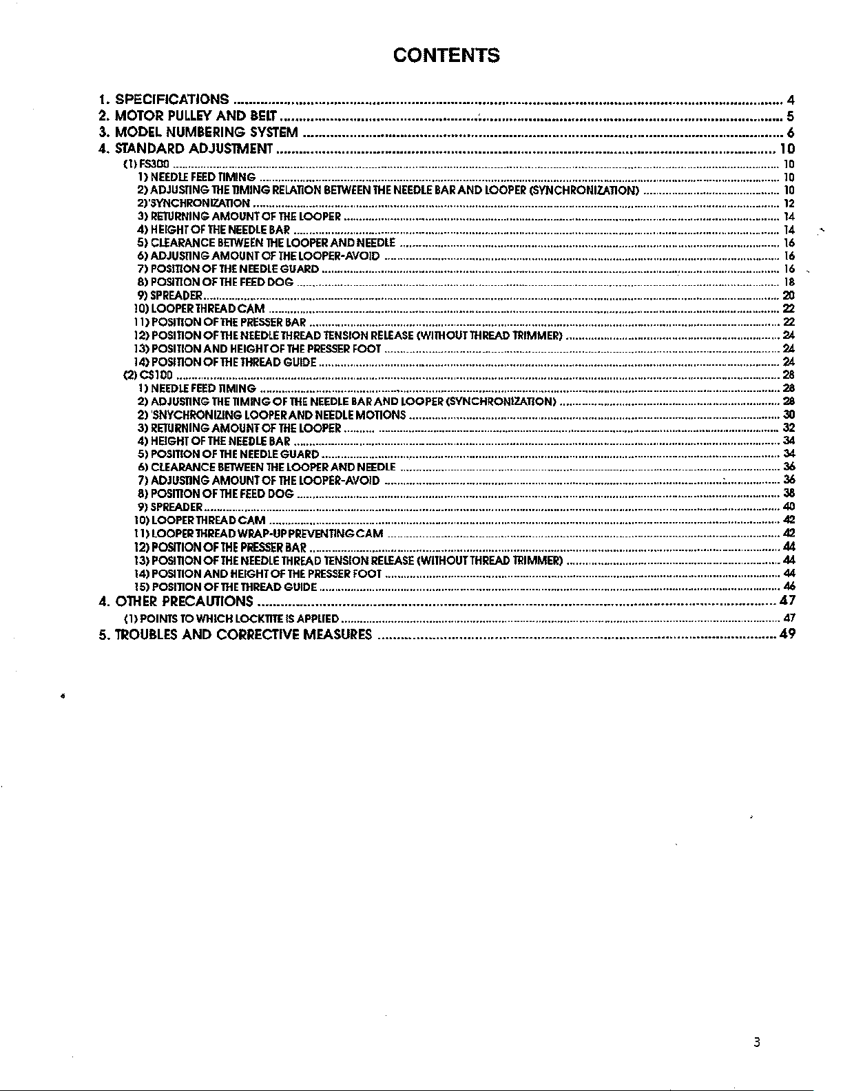
CONTENTS
1.
SPECIFICATIONS
MOTOR
2.
3.
MODEL
STANDARD
4.
{l)FS300 ...................................................................................................................................................................................................
<2>CS100 .................................................................................................................................................................................................. 28
4.
OlHER
(1)
5.
TROUBLES
PULLEY
NUMBERING
ADJUSTMENT
1)
NEEDlE
2)ADJUSTING
2)'SVNCHRONIZATJON
3)
4)HEIGHTOFTHENEEDLEBAR
S)
6)ADJUSTINGAMOUNTOFTHELOOPER-AVOID ...............................................................................................................................
7)
8)
9)
10)
II)
12)
13)
14)
1)
2)
2)
3)
4)
5)
6)
7)
8)
9)
10)
11)
12)
13)
14)
15)
FEED
RETURNING
Cl£ARANCE
POSmONOFTHENEEDLEGUARD
POSITION
SPREADER
LOOPER
POSITION
POStnON
POSlJION
POSinONOFTHETHREADGUIDE
NEEDLE
FEED
ADJUSTING
'SNYCHRONIZING
RETURNING
HBGHT
OF
POSmON
CLEARANCE
ADJUSDNG
POSmON
SPREADER
LOOPERTHREADCAM
LOOPER
POSITION
POSITION
POSITION
POSITION
PRECAUTIONS
POINTS
TO
AND
...•.............•••......•....•.•.•••..........•..........•...••.•••......••••.•••••••••••••••••••••.•••••••••••.••••.•••••••••••••••..•••••.
AND
BELT
.••••••••.••...•.•••••.•••..........•..•.••.......•
SYSTEM
............................................................................................................................ 6
; .............................................................................. 5
.•••••••...••••••.....••..•••••••••••••.••••...••.•••....•.•••....•.........••..•..........•.•....••••••......•.•...•....•......•
TIMING
THE
AMOUNT
BETWEEN
OF
......................................................................................................................................................................................... 20
THREAD
OF
OFTHENEEDLETHREAD
AND
TIMING
THE
AMOUNT OF
THE
OF
BETWEEN
AMOUNT
OF
......................................................................................................................................................................................... 40
THREAD
OF
OF
AND
OF
.......................................................................................................................................................................
TIMING
RELATION
.........................................................................................................................................................................
OF
THE
THE
THE
FEED
DOG ...........................................................................................................................................................
CAM .................................................................................................................................................................... 22
THE
PRESSER
HEIGHT
OF
.......................................................................................................................................................................
TIMING
OF
LOOPER
NEEDLE
THE
THE
THE
THE
HEIGHT
THE
THE
BAR
NEEDLE
GUARD
THE
OF
THE
FEED
DOG ...........................................................................................................................................................
....................................................................................................................................................................
WRAP-UP
PRESSER
NEEDLE
THREAD
OF
THREAD
BETWEEN
LOOPER
............................................................................................................................................................
LOOPER
BAR
THE
LOOPER
BAR
GUIDE
AND
...................................................................................................................................................
....................................................................................................................................................... 22
TENSION
PRESSER
....................................................................................................................................................
THE
NEEDLE
AND
NEEDLE
LOOPER
............................................................................................................................................................
................................................................................................................................................... 34
AND
LOOPER-AVOID
PREVENTING
....................................................................................................................................................... 44
TENSION
THE
PRESSER
....................................................................................................................................................
tHE
NEEDLE
BAR
AND
LOOPER
............................................................................................................................................
NEEDLE
FOOT
BAR
MOTIONS
................................................................................................................................................ 32
NEEDLE
CAM .............................................................................................................................. 42
FOOT
..........................................................................................................................
RELEASE
AND
RELEASE
(WITHOUT
............................................................................................................................... 24
LOOPER(SYNCHRONIZATION)
....................................................................................................................... 30
..........................................................................................................................
............................................................................................................ : .................. 36
(WITHOUT
...............................................................................................................................
THREAD
THREAD
(SYNCHRONIZATION)
TRIMMER)
TRIMMER)
.....................................................................
....................................................................... 28
..................................................................... 44
.................•.••.................••....
...................................................................................................................................... 47
WHICH
LOCKTTTE
CORRECTIVE
IS
APPLIED
MEASURES
.............................................................................................................................................
....................................................................................................... 49
4
10
10
10
10
12
14
14
16
16
16
18
24
24
28
34
36
38
42
44
46
47
•
3
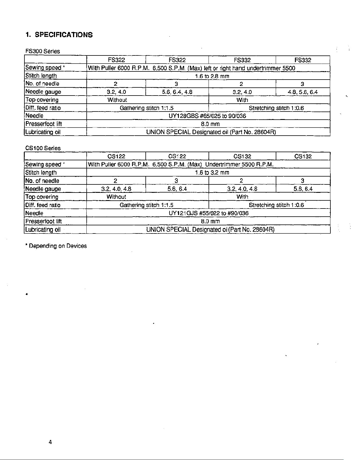
1.
SPECIFICATIONS
FS300 Series
FS322
Sewing
Stitch length
No.
Needle gauge
Top covering
Oiff.
Needle
Presserfoot lift
Lubricating oil UNION SPECIAL Designated oil (Part No. 28604R)
CS1
Sewing
Stitch
No.
Needle gauge 3.2,
Top
Diff.
Needle UY12t GJS #55/022 to #90/036
Presserfoot lift
Lubricatina
speed
~
of
needle
feed
ratio Gathering stitch 1
00
Series
speed
~
lenQth
of needle 2 3
covering
feed
ratio
With Puller
With Puller 6000 R.P.M. 6,500 S.P.M. {Max) Undertrimmer 5500 R.P.M.
6000
2
3.2,
4.0 5.6, 6.4, 4.8 3.2, 4.0
Without
CS122
4.0, 4.8 5.6, 6.4 3.2, 4.0, 4.8 5.6, 6.4
Without With
Gathering stitch 1
oil
I
R.P
.M.
I
UNION SPECIAL Designated
FS322
6,500 S.P.M.
3 2
:1.5
UY128GBS
CS122
:1.5
I
(Max) left
1.6to
or
2.8 mm
#65/025 to 90/036
B.Omm
I
1.6to3.2mm
B.Omm
FS332
right hand undertrimmer 5500
With
Stretching stitch 1
CS132
2
Stretching stitch 1 :0.6
oii(PM
No. 28604R)
I
I
4.8, 5.6, 6.4
I
I
FS332
3
:0.6
CS132
3
'*
Depending
•
on
Devices
4
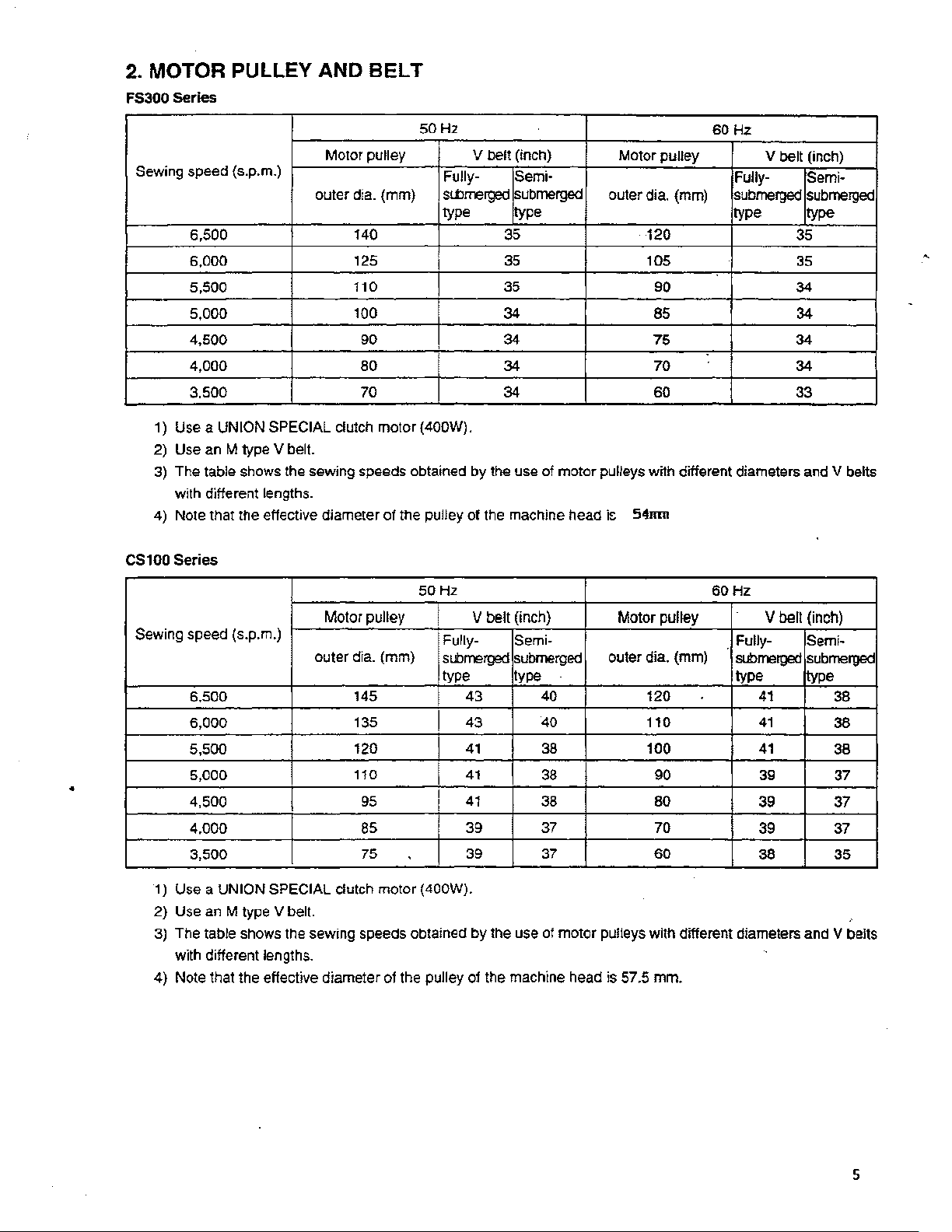
2. MOTOR PULLEY AND
FS300 Series
BELT
Sewing speed {s.p.m.)
6,500
6,000
5,500 110 35 90
5,000
4,500 90 34 75 34
4,000
3,500 70 34 60 33
1) Use a UNION SPECIAL clutch
2) Use
3)
4) Note that the effective diameter
CS100
an
M type V belt.
The table shows the sewing speeds obtained
with different lengths.
Series
50
Motor pulley
outer dia. (mm)
140 35
125
100
80
motor
{400W).
of
the pulley
Hz
V belt (inch)
Fully-
s!bmerged
type type type
.
Semi-
submerged
so
Hz
Motor
pulley
Fully-
outer dia. (mm) submerged
120 35
I
35
105
34 85 34
34 70 34
by
the use
of
the machine head
of
motor
pulleys with different diameters and V belts
i~
54mn
V belt (inch)
Semi-
submerged
type
35
34
50
Hz
Motor pulley v belt (inch)
Sewing speed (s.p.m.)
outer dia. (mm)
6,500 145 43
6,000
5,500
•
5,000
4,500
4.000
3,500
1)
Use a
UNION
2)
Use
an
3)
The table shows the sewing speeds obtained
with different lengths.
4) Note that the effective diameter of the pulley
SPECIAL clutch
M type V belt.
135
120
110
95
85
75
motor
Fully- Semi-
submerged
type type type
submerged
40
43 40 110
I
I
I
I
I
(400W).
41
41
41
39
39
by
the use of
of
the machine head is 57.5 mm.
38 100
38
38 80
37 70
37
motor
Motor pulley V bell
outer dia. (mm)
120
90
60
pulleys with different diameters and V belts
60Hz
. Fully- Semi-
subrre'lJE'f
41
41
41
39
39 37
39 37
38
(inch)
submerged
type
38
38
38
37
35
5
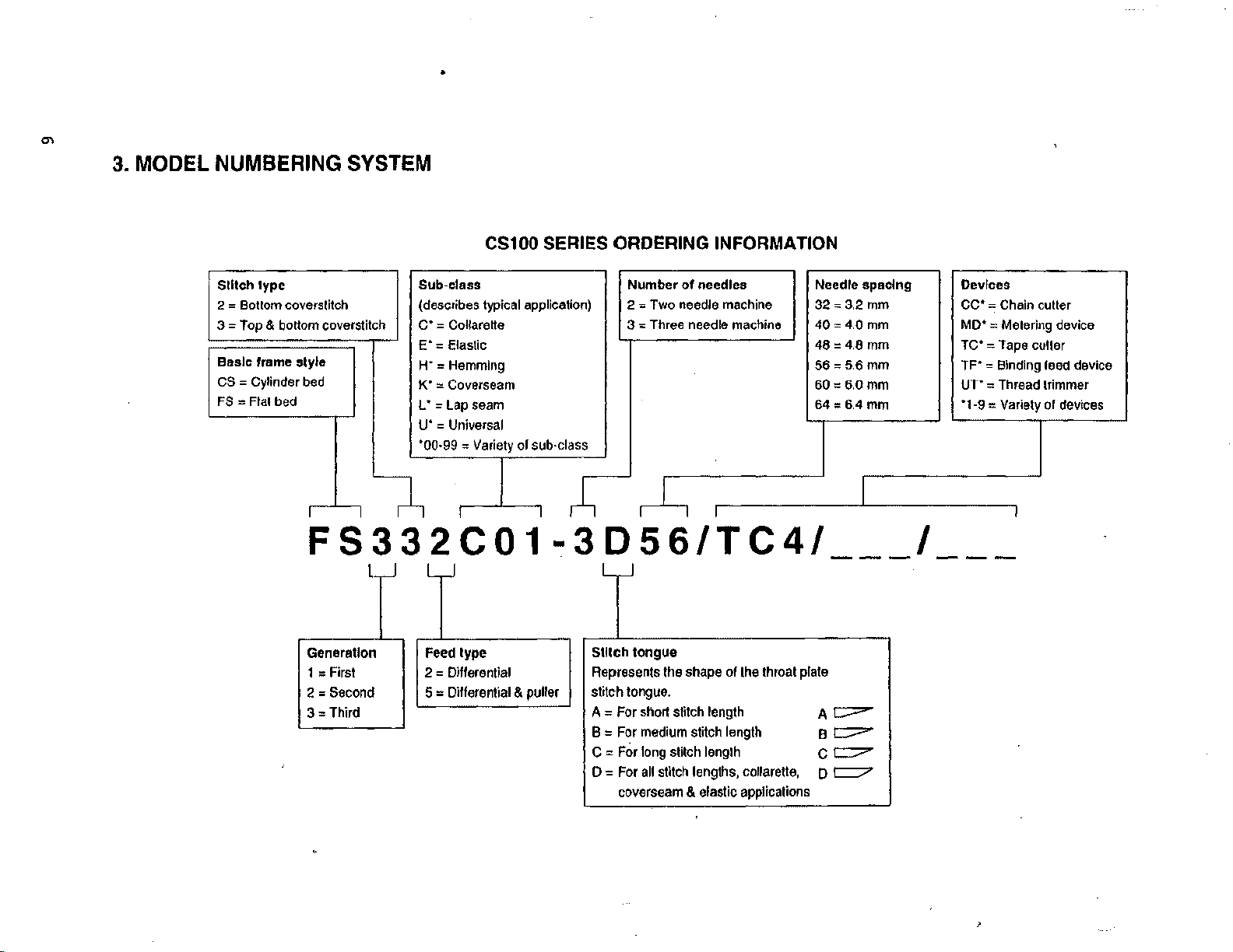
3. MODEL NUMBERING SYSTEM
•
CS100 SERIES ORDERING INFORMATION
Stitch type Sub-class
2 = Bot!om coverslitch
3 =Top & bottom coverstitch
Basic
frame style
CS
= Cylinder
FS
=Flat
bed
bed
I I
(describes typical application)
c· = Col!arette
E'
=Elastic 48 = 4.8
H":
Hemming
K'
= Coverseam
L •
=lap
U'
= Universal
'00·99
" Variety
FS332C01-3D56/TC4/
l
Generation Feed type
1 =First 2 = Dlflerential
2 =Second 5 = Differential & puller
=Third
3
seam
ol
sub-class
Number
2
3 "' Three needle machine
~
Stllch tongue
Represents
stitc-h
tongue.
A = For short stitch length
B =
For
C =
For
0
=
For
coverseam & elastic applications
of
"'
Two
needle machine
l
I
the
shape
medium
long stitch length
all
stitch lengths, collaretle,
needles Needle
32"'
40=4.0mm
56"'
60=6.0mm
64
= 6.4
of
the
throat plate
A
c;:=-
stitc-h
length
Bt:='"
c c::::7'"
D='"
spacing
3.2
mm
mm
5.6
mm
mm
I
Devices
CC'
= Chain cutter
MD'
= Metering device
TC'
"'Tape
TF'
= Binding feed device
UT" = Thread trimmer
'1-9
= Variety
I
culler
or
devices
•
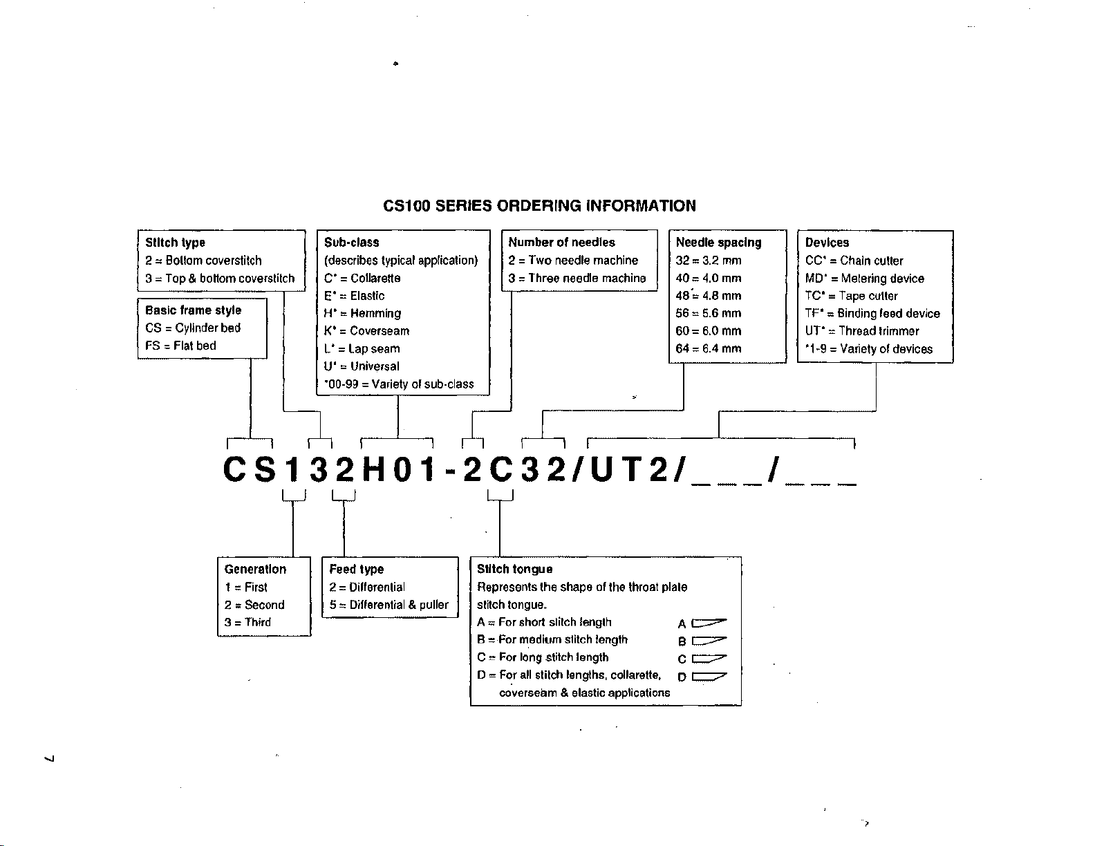
CS100 SERIES ORDERING INFORMATION
SUtch
type
2 = Bottom coverstitch (describes typical application) 2
3
=Top
& boHom coverstitch
Basic
frame style
CS
= Cylinder bed
FS
=Flat
bed
I
I
Sob-class
C' = Co1larette
E'
=Elastic
H'
=Hemming
K'
= Coverseam
L'
=Lap
seam 64 = 6.4 mm
U'
=Universal
=Variety
'00-99
I
or
sub-class
I
l
CS132H01-2C32/UT2/
Generation Feed type
1
=First
=Second
2
3
=Third
2 = Differential
5 = Differential & puller stitch tongue.
Stitch
Represents the shape
A
"'
For short slilch length
8
"'
For medium stitch length
C
""
For long stitch length
D = For all stitch lengths, collarelle,
coverseam & elastic applications
Number
3 = Three needle machine
of
=Two
needle machine
needles
.
~I
tongue
of
the throat plate
Needle
spacing
32"'
3.2
mm
40=
4.0 mm
48·,
4.8 mm
56=
5.6 mm
60=6.0mm
I
A~
Be?"
c
=""
D
t:::7
I
Devices
cc·
"' Chain culler
MD'=
Metering device
TC'
=Tape
culler
TF'
= Binding feed device
UT"
= Thread trimmer
'1·9
= Variety of devices
I
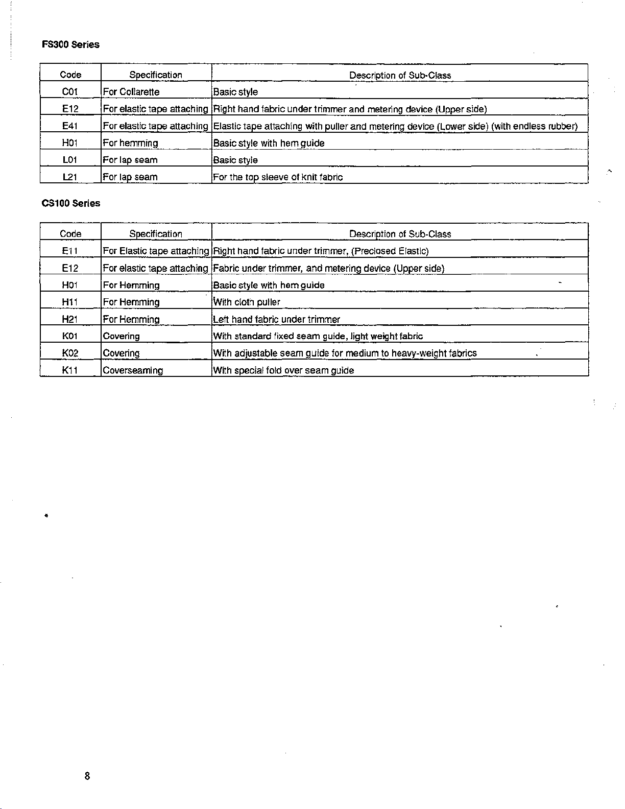
FS300
Series
Code
C01
E12 For elastic tape attaching Right hand fabric under trimmer and metering device (Upper side)
E41
H01
L01
L21
C$100
Series
Code Soecification Description of Sub-Class
E11
E12 For elastic tape attaching Fabric under trimmer,
H01
H11
H21
K01
K02 Covering With adjustable seam guide for medium to heavy-weight fabrics
K11
Specification
For Cellarette Basic style
For
elastic taoe attaching Elastic tape attaching with puller
For
hemming Basic style with hem guide
For
lap seam Basic style
For
l_ap_
seam For the top sleeve of
For Elastic tape attaching Right hand fabric
For Hemming Basic style with hem guide
For Hemming With cloth puller
For
Hemming Lett hand fabric under trimmer
Covering With standard fixed seam guide, light weight fabric
Coverseaming With special fold over seam guide
knit
under
trimmer, (Preclosed Elastic)
and
Description of Sub-Class
and
metering device (Lower side) (with endless rubber)
fabric
metering device (Upper side)
-
•
8
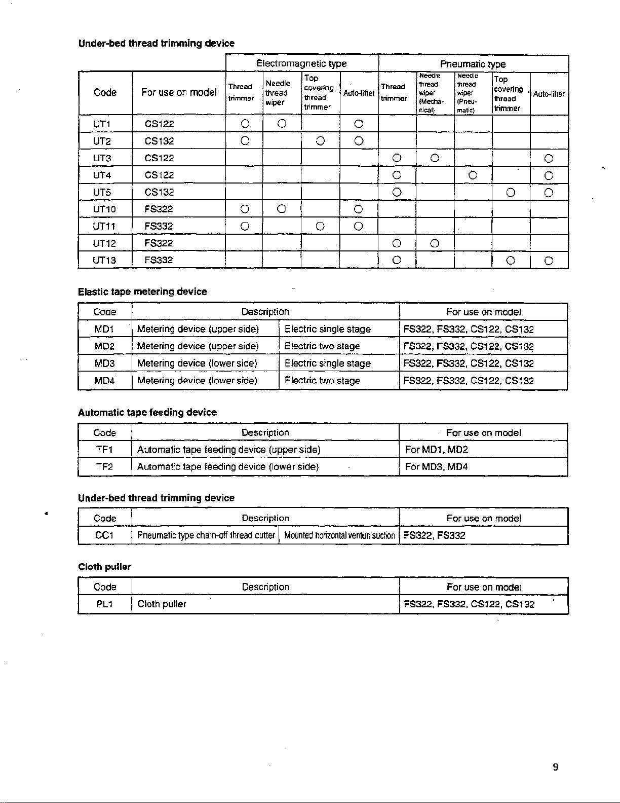
Under-bed thread
trimming
device
For
Code
UT1
UT2
UT3 CS122
UT4 CS122
UTS
UT10 FS322
UT11 FS332
UT12
UT13
Elastic tape metering
Code
MD1
MD2 Metering device (upper side)
MD3
MD4
use on model
CS122
C$132
C$132
FS322
F$332
device
Metering device (upper side) Electric single stage
Metering device
Metering device (lower side) Electric
(lower side) Electric single stage FS322, FS332, C$122, CS132
Electromagnetic type
Thread
trimmer
Needle
thread
wiper
Top
covering
thread
trimmer
0 0
0
0
0
0
0 0 0
Description
Electric
two
two
Auto-lifter
0
0
0
stage
stage
Pneumatic
Needle Needle
_,
Thread
trimmer
•~o
(Mecha- (Pneu-
nieal) matie)
0 0
0 0
0
0 0
0
For
FS322, FS332, CS122,
F$322,
FS322, FS332, C$122,
F$332,
type
•~o
wiper
Top
covering
thread
trimmer
use on model
CS122,
•
Auto-lifter
0 0
0
C$132
CS13~
C$132
0
0
0
Automatic tape feeding
Code
TF1
TF2
Under-bed thread
•
Code
CC1
Cloth
Code
PL1
I
Automatic
Automatic tape feeding device (lower side)
Pneumatic
puller
Cloth puller
device
Description
tape feeding device (upper side)
trimming
type
device
chain-off
Description
thread
cutter l Mounted
Description
horizontal
venturi
suction
For
use on model
For
MD1,
MD2
ForMD3,
FS322,FS332
FS322, FS332, CS122, CS132
M04
For
use on model
For
use on model
>
9
4. STANDARD ADJUSTMENT
(1) FS300
Standard Adjustment
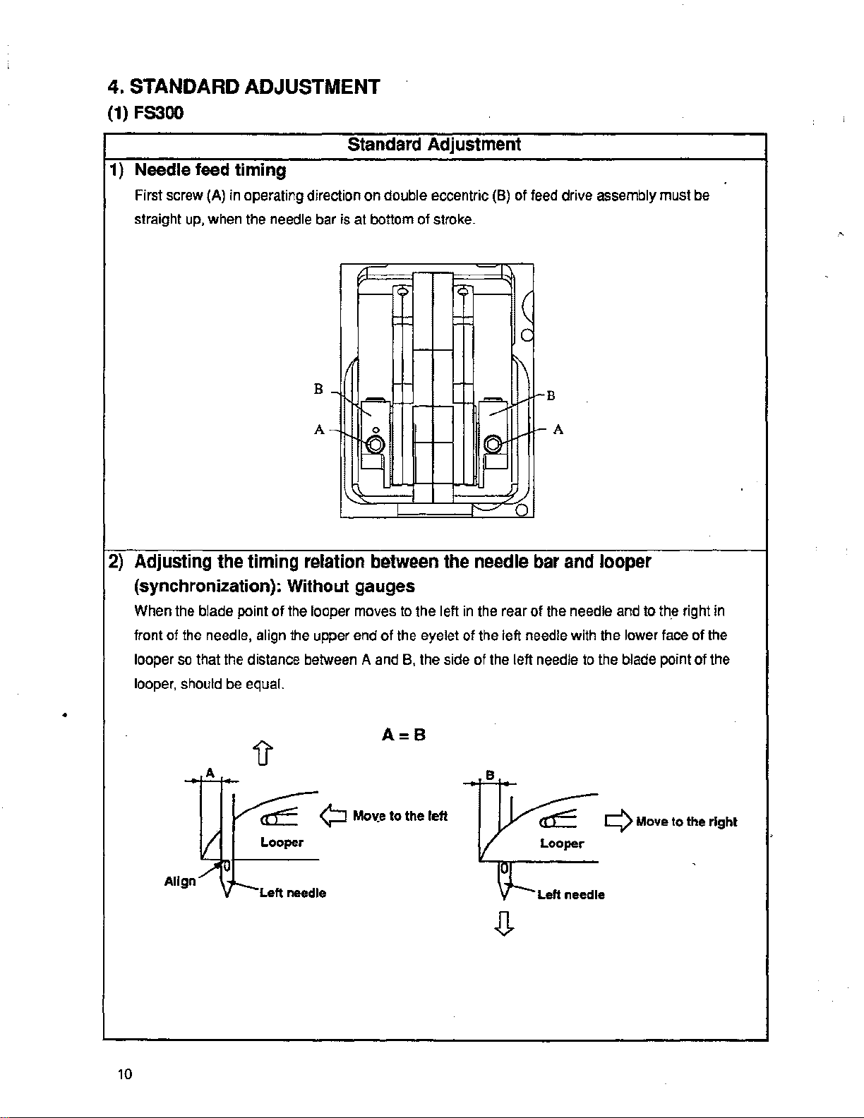
1) Needle feed timing
First screw
straight
(A)
in
operating direction on double eccentric
up,
when the needle bar is at bottom of stroke.
(B)
of feed drive assembly must
r--
I~
i\
B
A-
'
il
-
2)
Adjusting the timing relation between the needle bar and looper
(synchronization): Without gauges
/
~
1---
1--B
f--A
0
.
be
When the blade point
front of
looper
looper,
•
the
needle, align the upper end of the eyelet of the left needle with the lower
so
that the distance between A and
should
be
of
the looper moves
equal.
to
the left
B.
the side of the left needle to the blade point of the
A=B
in
the rear of the needle
and
to
th_e
face
right
of the
in
4J'
A
'¢:J
/ca:::
I
Allgn~L
Looper
Left
needle
Mov:e
to the left
B
Vca=
v
tl--
Looper
Left needle
¢Move
to
the
.
right
.
.0.
10
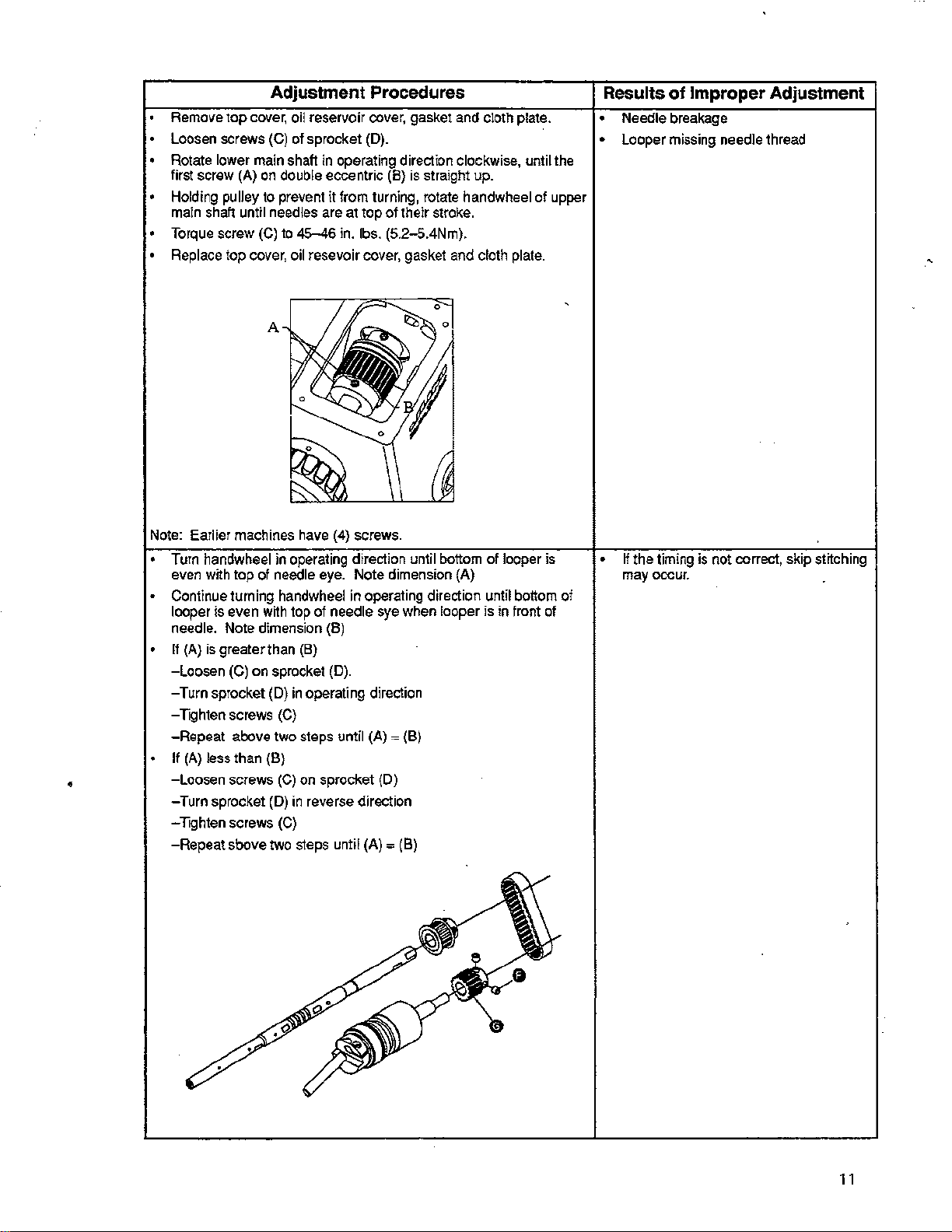
Adjustment Procedures
Remove
Loosen screws (C) of sprocket (D).
• Rotate lower
first screw (A) on double eccentric (B) is straight up.
•
Holding
main
•
Torque
•
Replace
Note:
• Turn handwheel in operating direction until bottom
even with tap of needle eye. Note dimension (A)
Continue
looper
needle.
•
If
-loosen
-Turn sprocket
-Tighten
-Repeat
If
•
•
-loosen
-Turn sprocket
-Tighten screws
-Repeat sbove
top
cover,
main
pulley
shaft
Earlier machines
is
(A)
is
(A)
less than
to
until
needles
screw
(C)
top
cover,
turning
even
w~h
Note dimension (8)
greater than (8)
(C)
on sprocket
(D)
screws
above
(B)
screws
(D)
two
oil
reservoir cover, gasket
shaft
in
operating direction clockwise, until
prevent
to
handwheel
(C)
two steps until (A)"' (8)
(C)
(C)
it
from turning,
are
at
top of their
45-46
in.
lbs. (5.2-5.4Nm).
oil
resevoir
have
top of needle
in
operating direction
on
in
reverse direction
s1eps
cover,
(4)
screws.
in
operating direction until bottom
sye
(D).
sprocket
(D)
until (A)"'
gasket
when
(B)
rotate
stroke.
looper
and
cloth plate.
handwheel
and
cloth
of
is
of
plate.
looper is
in
front
the
upper
of
Results
• Needle breakage
• Looper missing needle thread
•
of
If
the timing
may
occur.
of
Improper Adjustment
is
not correct, skip
st~ching
11
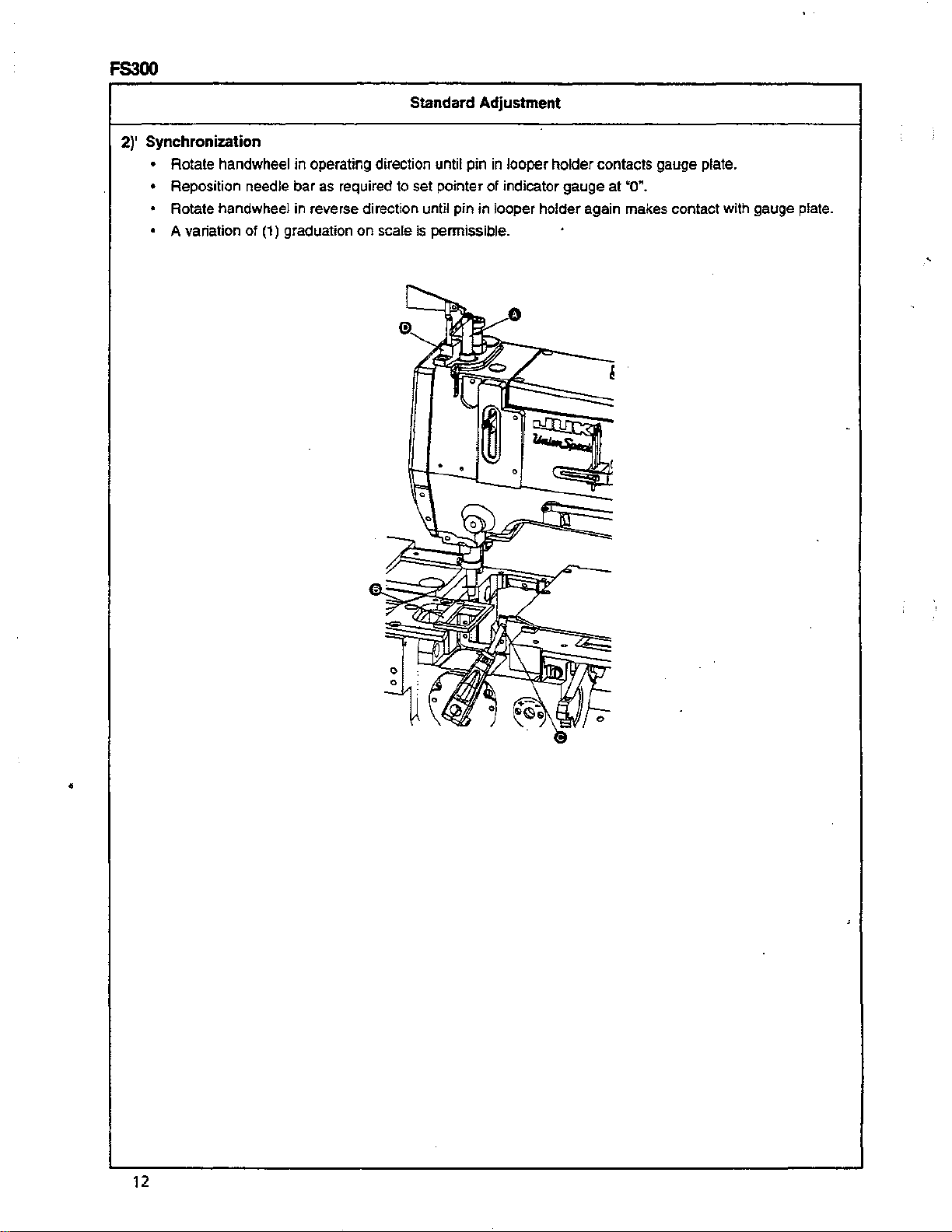
FS300
2)' Synchronization
• Rotate handwheel
• Reposition needle bar as required to set pointer
• Rotate handwheel in reverse direction until
• A variation
of
in
operating direction until
(1) graduation
on
scale is permissible .
Standard Adjustment
pin
in
looper holder contacts gauge plate.
of
indicator
pin
in looper holder again makes contact with gauge plate.
gauge
at
"0~.
•
12
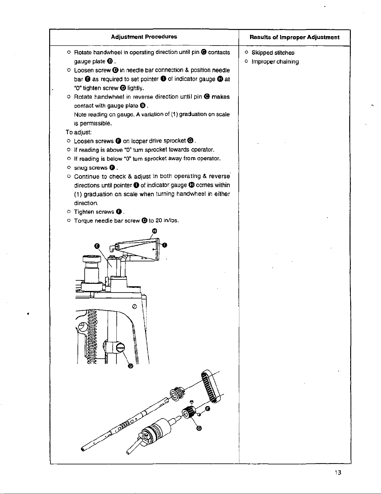
Adjustment Procedures
Results of Improper Adjustment
o Rotate handwheel in operating direction until pin (9 contacts
gauge plate
o Loosen screw (!) in needle bar connection & position needle
bar
8 as required
~a~
tighten screw (!)lightly.
o Rotate handwheel
contact with gauge plate
Note reading on gauge. A variation of
is permissible.
To adjust:
o Loosen screws
o If reading is above
o
If reading is below "0" tum sprocket away from operator.
o snug screws
o
Continue
directions until pointer 0 of indicator gauge
(1) graduation
direction.
o Tighten screws
o Torque needle bar screw
to
e .
to
set pointer 0 of indicator gauge 0 at
in
reverse direction until pin 8 makes
0 .
0
on
looper drive sprocket
~a"
tum sprocket towards operator.
0 .
check
& adjust in both operating & reverse·
on
scale when turning handwheel
0.
(9
to 20 inllbs.
(1)
graduation
€t
on
.
4D
comes within
in
scale
either
CD
o Skipped stitches
o
Improper chaining
•
13
FS300
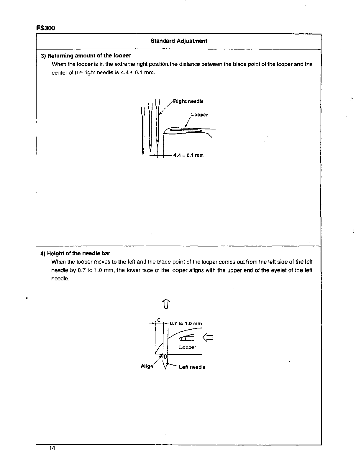
3) Returning
When the looper is
center of the right needle is 4.4 ±
amount
of
the
in
the extreme right position,
looper
0.1
Standard
mm.
}
Adjustment
the
/Right
V Looper
c=
-+-+---
4.4 ± 0.1
distance between the blade point
needle
I
mm
of
the looper and the
•
4) Height
of
the
needle
When the looper moves
needle
needle .
by 0.7 to 1.0 mm, the lower face of the looper aligns with the upper end
bar
to
the left and the blade point of the looper comes out from the left side of the left
of
the eyelet
c
-I"'-J-0.7to
I/
1.0
Looper
mm
~of---
Align/
Lett
needle
of
the left
14
Adjustment
Procedures
Results
of
Improper
Adjustment
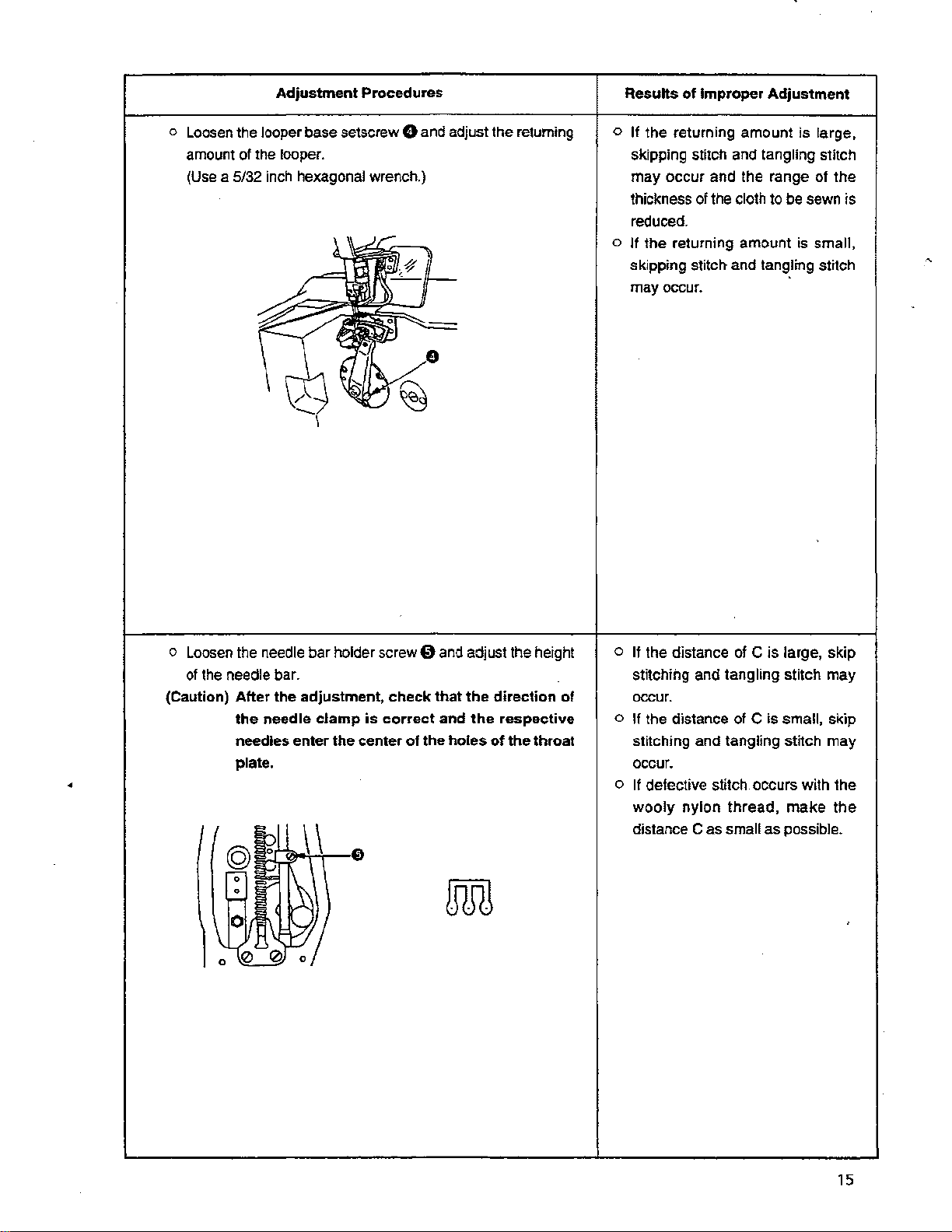
o Loosen the looper base setscrew
amount of the
(Use
a 5/32
lOoper.
inch
hexagonal wrench.)
0 and adjust the returning
o If the returning amount is large,
skipping stitch and
may occur and the range of the
thickness of the cloth to be sewn is
reduced.
o If the returning amount is small,
skipping stitch and tangling stitch
occur.
may
tangling stitch
o Loosen the needle bar holder screw 0
of
the needle bar.
(Caution)
After
the adjustment,
the
needle
needles enter the center
plate.
clamp
check
is
correct
•
0
@
0
0
0
0 0
\\
0
of
that
the
and
adjust the height
the
direction
and
the
respective
holes
of
the
mill
of
throat
o If the distance of C is large, skip
stitching and tangling stitch may
occur.
o If the distance of C is small, skip
stitching and tangling stitch may
occur.
If
defective stitch occurs with the
o
wooly
distance C as small as possible.
nylon thread,
make
the
15
FS300
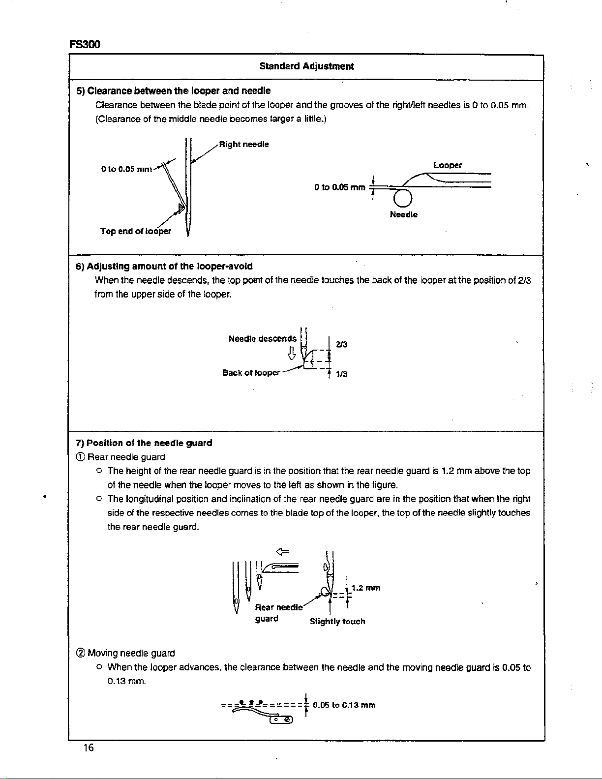
5) Clearance between
Clearance between the
(Clearance
Otoo.os
Top end
6)
Adjusting
When the needle descends, the top point
from the
of
mm
of
amount
upper
the
looper
blade
point
the
middle needle becomes larger a liHie.)
VRight
looper
of
the looper-avoid
side
of
the looper.
and
Needle
Standard
needle
of
the looper
needle
of
desce:tlr
Adjustment
and
the grooves
Oto0.05mm4
the needle touches the
~
i
>13
of
the rightlleft needles is 0 to 0.05 mm.
Looper
j
===;~/~::::-;;::::~;.
;;;;
j
0
Needle
back
of
the looper
at
the position of
213
Back
of
looper
7) Position
<D
Rear
•
of
the needle
needle
o
The
of
o The longitudinal position
side of the respective
the rear
height
the
guard
of
needle
needle
guard
the rear needle guard is in the position
when
the
needles comes to the blade top
guard.
looper
and
moves
inclination
to the left as shown in the figure.
of
the rear needle guard are in the position that
t
113
that
the rear needle guard is 1.2
of
the looper, the top
of
mm
above the top
when
the
needle slightly touches
the right
<?
~
~
!.:.;
guard Slightly
==~t.2mm
touch
® Moving needle guard
o When
the
0.13mm.
looper
advances, the clearance between the needle
and
the moving needle
guard
is
0.05 to
==J~;;:~=t
16
0.05to0.13mm
Adjustment
Procedures
Results
of
Improper
Adjustment
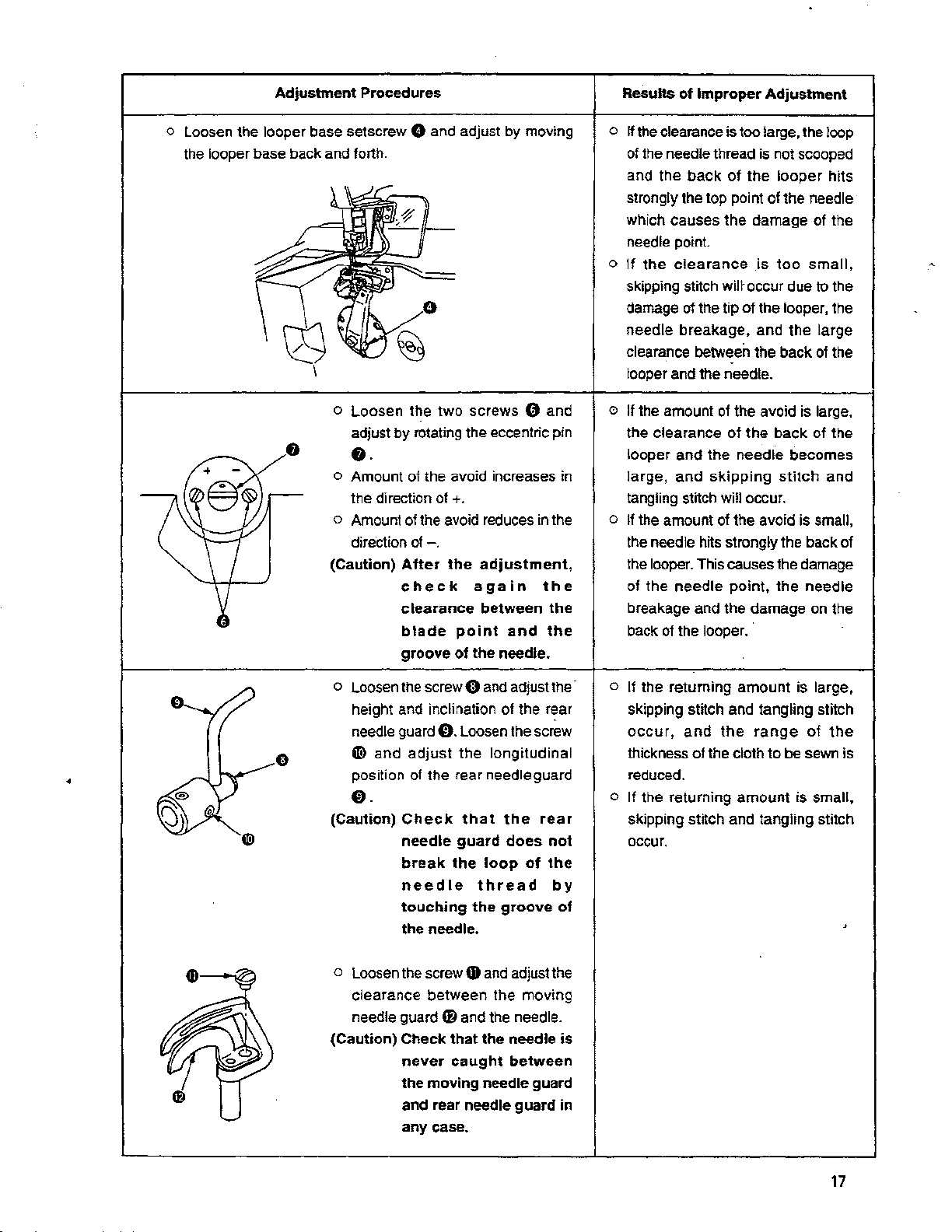
o Loosen the looper base setscrew 0 and adjust by moving
the looper base back and forth.
o Loosen the two screws G and
adjust by rotating the eccentric pin
8.
0 Amount of the avoid increases in
the direction
o Amount
direction
(Caution)
of+.
of
the avoid reduces
of-.
After
the
adjustment,
check
clearance
blade
groove
again
between
point
of
the needle.
and
in
the
the
the
the
o
If
the clearance is too large, the loop
of the needle thread is not scooped
back
of
the
and the
strongly the top point of the needle
which causes the damage
the
point
clearance
otthe
tip
.
of
of
and
skipping
will occur.
needle
o
If
skipping stitch will· occur due to the
damage
needle breakage, and the large
clearance between the back
looper and the needle.
o If the amount
the clearance
looper and the needle becomes
large,
tangling stitch
looper
is
too
of
the looper, the
the avoid is large,
the
back
stitch
hits
of
the
small,
ot
the
of
the
and
o If the amount of the avoid is small,
the needle hits strongly the back of
the looper. This causes the damage
of the
breakage and the damage on the
back
needle
of
the looper.
point,
the needle
o Loosen the
height and inclination of the
needle guard
G'!>
and
•
position
0.
(Caution)
o Loosen the screw
clearance between the moving
needle guard
(Caution)
screwO
0.
adjust
of
the rear needle guard
Check
needle
break
needle
touching
the needle.
Check
never
the
moving
and rear needle
any case.
and adjust the-
Loosen the screw
the
longitudinal
that
the
guard
the
fD
that
caught
does
loop
thread
the
groove
Gt
and
adjust the
and the needle.
the needle
between
needle guard
r~ar
rear
not
of
the
guard
by
of
is
in
If
the returning
o
skipping stitch and tangling stitch
occur,
thickness
reduced .
and
o If the returning
skipping stitch and tangling stitch
occur.
amount
the
of
the cloth to be sewn is
amount
range
is large,
of
is small,
the
17
FS300
Standard Adjustment
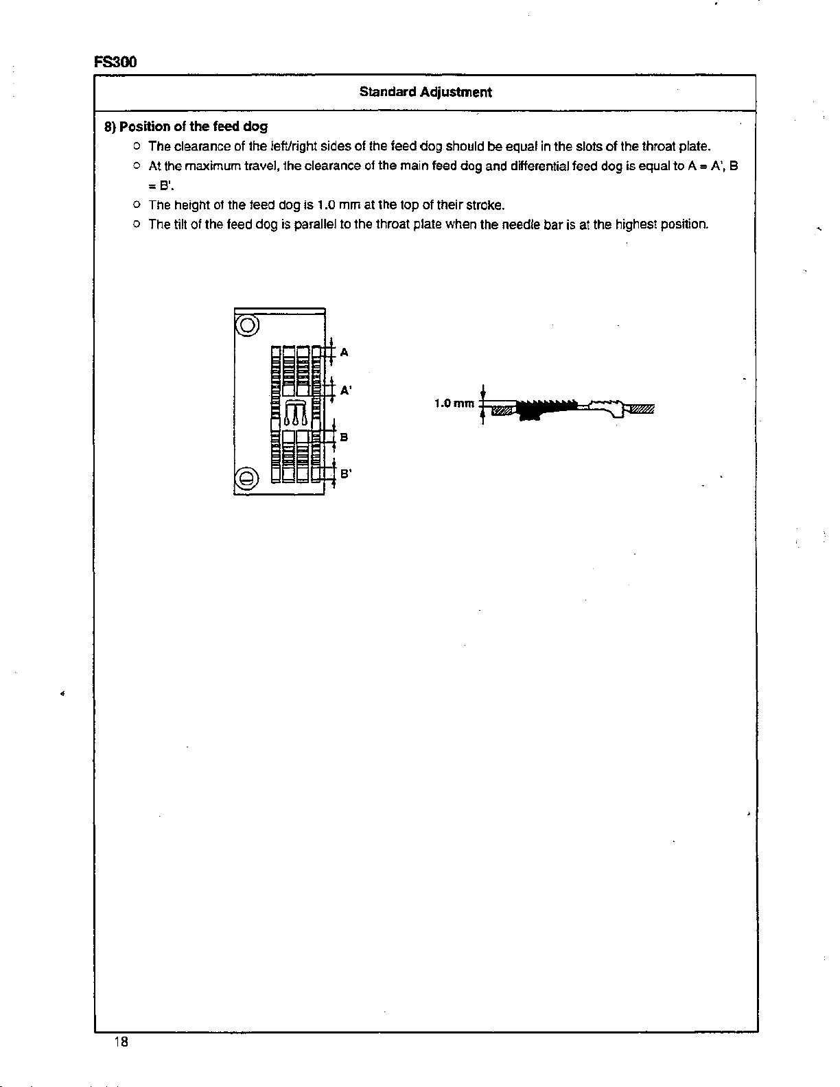
8} Position
of
the
feed
dog
o
The
clearance of the left/right sides of the feed
At
the maximum travel, the clearance of the main feed dog and differential feed
o
dog
:8'.
o The height of the teed dog is 1.0 mm at the top of their stroke.
tilt of the feed dog is parallel
o The
to
the throat plate when the needle bar is at the highest position.
1.0mm
should
be
equal
in
the slots
of
the throat plate.
dog
is equal to
A=
A', 8
•
18

Adjustment
Procedures
Results
of
Improper
Adjustment
Open the cover located at the rear side of the needle entry.
o Adjust
o Adjust the longitudinal position of the differential feed dog
the
longitudinal position of the main feed dog after
loosening the
after loosening the nut
nut@) and rotating the eccentric nut
Q)
and rotating the eccentric nut
ID.
0.
o Adjust the inclination of the feed dog after loosening the screw
4D
and rotating the eccentric shaft inside with a slit-screwdriver
through the hole
~.
o If the letvright positions of the feed
dog are
and the throat plate
o Heating and abnormal noise will
produced.
o The feed components
early. And,
and
produced.
o If the inclination
raised toward you, starting
workpiece
incorrect,
abnormal
the left/right sides
will wear out.
the looseness, bending
noise
of
the feed dog
will
be
affected.
wiH
be
wear out
will
be
of
the
o If the inclination of the feed dog is
towered toward you,
the
irregular
puckering .
it
may
stitching
cause
and
is
•
o Loosen the screw
dog@).
o Loosen the screw
feed dog
@1.
G>
and adjust the height of the main feed
§)
and adjust the height of the differentia!
o
If
the position of the feed dog
it
causes
stitching and defective chain-off.
the
return
is
feed,
o If the main feed dog, differential
dog and throat plate come
each
other,
breakage.
o
If the position
the
stitch
when the sewing is finished.
it
of
the
length
will
in
cause
fe:ed
dog is low,
becomes
contact
high,
skip
feed
the
short
19
FS300
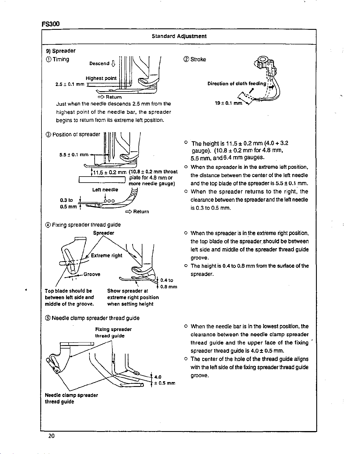
9)
Spreader
(!)Timing
2.5 ±
0.1
Just
when
highest point of the needle bar, the spreader
begins to return from its extreme left position.
®Position
5.5 ±
0.3
to
0.5
mm
Descend.[!,
Highest
mm
c~~~~~g~~~~
the
of spreader
0.1
mm
~j=ii::;:f~i,~o~o'::;:;/
f
point
.:::0
Return
needle descends 2.5
II
..,.-JIHI
11.5
Left needle
~
:±
0.2
mm
(10.8 ±
plate for 4.8 mm
more
~Return
mm
0.2
needle gauge)
Standard
from
the
mm
throat
or
Adjustment
@Stroke
•..
Direction
o The height is 11.5 ±
gauge).
5.6
mm.
o When the spreader is in the extreme left position,
the distance between the center of the
and the top blade of the spreader is
o When the
clearance between the spreader and the left needle
0.3
to
is
0.5 mm.
o1
19±
0.1
mm
(10.8 ± 0.2
and
6.4
mm
spreader
cloth feeding
~ l';"'''
,
~~--.--..~
0.2
mm
mm
for4.8
gauges.
returns
fl..
,,
,,
(4.0 + 3.2
mm,
left needle
5.5
± 0.1
to
the
right,
mm.
the
@Fixing
•
Top
between left
middle
®Needle
spreader thread guide
Spreader
Extreme
blade
of
the
should
be
side
and
groove.
clamp spreader thread guide
Fixing
thread
right
Show
spreader at
extreme
when
setting
spreader
guide
right
\
position
height
0.4to
o.a
mm
is in
~he
o When the spreader
the top
left side and middle
groove.
o The height
spreader.
o When the needle bar is in the lowest position, the
clearance between the needle
thread guide and the
spreader thread guide is 4.0 ± 0.5 mm.
o The center of the
with the left side of the fixing spreader thread guide
groove.
blade of the spreader
is
0.4 to 0.8 mm from the surface
hole of the thread guide aligns
extreme right position,
__
should be between
of·
the spreader thread guide
clamp spreader
upper
face
of
the fixing '
of
the
Needle
clamp
spreader
thread
guide
20

Adjustment
Procedures
Results
of
Improper
Adjustment
o Adjust
eccentric cam
o Adjust the stroke by loosening the nut G
forth.
and to the back
the
timing
@)
and rotate the spreader eccentric cam
If it
is
moved toward you,
it
becomes large.
by
loosening
screw
€!)
of
the
and
move back and
the
stroke becomes small,
spreader
~.
o Adjust the height of the spreader by loosening the screw@)
and moving the spreader 0 up and down.
o Adjust the clearance between
by loosening the
and forth.
o Adjust
the
and move the spreader G
screw@)
extreme left position
the
spreader and left needle
and
move the
by
loosening the screw G
to
the left and right.
0 <
spreader 0 back
o If the timing is too advanced,
needle does not catch the covering
thread when it descends. This
likely to cause the skipping stitch.
On
the
contrary, if the timing
retarded,
to break
covering thread is
spreader becpmes
o If
the
spreader
skip stitching
thread.
o If
the
set right,
of the top covering thread.
; o
If
spreader and needle is small, it will
cause
large,
the top covering thread.
o If
the
spreader
uneven stitching of the top c9vering
thread.
stitching of the top covering thread.
the
right needle is likely
as the resistance when the
pulled from
large~
movement
is
not set right, it will cause
height
it will cause skip stitching
the
clearance
the
needle breakage. If it is
it will cause skip stitching of
protruding
is
If
it
is
amount
of
the top
of the spreader is no!
between
amount
large,
small, it will cause skip
it
will
the
is
is
too
the
of
the
covering
the
of
the
cause
o Adjust the fixing spreader thread
screw~.
guide~
by loosening the
•
o
Adjust
loosening the screw @).
the
needle
clamp
spreader
thread
guide G by
o If the height
thread guide
the top covering
spun
defective looping
other threads are used.
If
1he
o
o If the position of the needle clamp
position of the fixed spreader
thread
cause
covering thread.
spreader thread guide
it
will cause skip stitching of the top
covering thread.
thread
guide
skip
of
the
fixed spreader
is
set as high as
perlonnance by the
is
improved.
may
occur when
is
not
correct, it will
stitching
of
the
is
not correct,
0.
8 ,
But,
top
21

FS300
10)
CD
Timing
Looper
Needle
descends
thread
Standard
cam
vthread
Looper
Adjustment
o When the looper thread is pulled from the highest
point of the looper thread cam, the top point
left needle aligns with the lower face
,(\
l];aackof
~
Align
face
of
ell
Position of looper thread guide plate and looper thread cam pawl wire
1.6mm
Looper thread
guide plate
looper
with
lower
looper
Tou~a--;::l;===·
looper
Looper
Wire
@
thread
thread cam
Looper
cam
thread cam
====:0~tj
pawl
9.6
o The height
mm from the lowest part
upper part
o
The
mm
o The looper thread cam pawl and wire are to
rear
the wire, and its front side is 9.6 mm above the
upper face
inside.
positioned in the
plate.
of
of
the looper thread guide plate is 1.6
of
the looper cam
of
the looper thread guide plate.
side of the looper thread
of
the wire at the highest place
center
of
cam
pawl
the
looper thread cam
of
the
the looper.
to
the •
touches
of
the
be
®Position
•
11)
Position
of thread guide and auxiliary thread tension
plate
guide
Auxiliary thread
of
the
presser
bar
o The. position of the
position that the looper thread
the
when
o Adjust
to make as
The
clearance between the presser bar. bracket and
the presser bar bushing
is
under
presser foot touches the upper face of the throat plate
at the
looper is in the extreme left.
the
tension of
low as the thread is
the
throat plate and the bottom face
time
that
thrE!ad
the
is
the needle
guide is to
auxiliary thread tension
0.8
mm
bar
is
be
set
just
becomes tight
just
stabilized .
when the feed dog
in
the lowest point.
at
of
the
the
22

Adjustment
Procedures
Results
of
Improper
Adjustment
o Adjust the timing of the looper thread cam
two screws
o Adjust the height of the looper thread guide plate by loosening
the screw
and down.
Adjust the looper thread cam pawl by loosening the
and move the looper thread cam pawl
Adjust the lateral relation of the looper thread guide plate by
loosening the screw
plate
®to
@I.
E1i)
and move the looper thread guide
ED
and move the looper thread guide
the left and
right
by
loosening the
61
up and down.
plate®
screwS
up
o If
the
timing
of
the looper thread
cam
is
too
advanced,
stitching on the back of the looper
will occur.
tightening
inferior.
If
it is too retarded, the
of
the
thread
the
will
skip
be
o If the clearance ·between the looper
thread
large, the looper thread suddenly
slackens and
back side will occur.
o If
the
damaged.
cam
pawl and
_skip
stitching on the
the
looper thread cam is not
center,
the
cam
the
wire
will
is
il'
be
(Caution)
o Adjust the position of the thread guide by loosening the two
screws$
Use a 3132" hexagonal
and move the thread guide
wrench
E@
for
the
(2 pes.)
screw
up
and down.
t!>.
o If
the
thread guide is raised, the
looper thread after sewing
slack.
will be
o It the thread guide is lowered, the
looper thread
•
o Adjust
by
loosening the two
bar bracket
€i)
up and down.
screws~
and move the presser
tight.
o
If
the
presser bar bracket and the presser
bar bushing is
face
of
contact tightly to the throat plate.
o
If the clearance is large, the lifting
amount of the presser foot
reduced.
after
clearance
small, the bottom
the
presser
sewing will be
between
toot
can
will be
the
not
23

FS300
Standard Adjustment
12)
Position
When the presser foot is raised by 3 mm, the thread tension opening
and when the presser foot is in the highest position, the thread tension disc opens and there is no tension
the thread.
of
the
needle
thread
tension
release
(without
thread
trimmer)
pawlet
3mm
touches the thread tension
=~=---'
Throat plate
6)
on
13) Position and height
CD
Adjust the position of the presser foot so that the needles enter the center
presser foot
CV
Adjust the height of the presser foot so that when the needle bar is
does not come out from the lower face of the presser toot.
•
Note:
On
elastic
of
the presser
on
condition that the presser toot is set correct to the presser bar.
foot
Needles
in
its highest point, the needle point
"'"'-'""'lf"'-'""""'"f
Throat
plate
machines
height
is
7.0
nm.
of
the needle entry holes in the
Lower
bushing
Spreader
Max.
8.0
mm
14) Position
<D
Middle thread guide and thread guide holder
ofthe
( Fix at the
thread
guide
extreme
Spun thread
Cotton thread
Wooly nylon thread
Tetoron thread
right
position
of
the
Left needle
thread
27mm
27mm
27mm
27mm
slot. )
24
£
Middle needle Right needle
thread thread
25mm
25mm 23mm
25mm 23mm
25mm 23mm
23mm

Adjustment Procedures
Results of Improper Adjustment
o Adjust
o Adjust the position by loosening the screw
o Adjust the height by loosening the
by
loosening the
E>
presser foot
~
and hit it to the lever<$ so that the needle top comes 0.3
mm
over from the lower part of the presser foot when the
needle is in its highest point. At this time, loosen the two
screws
collar and the lower bushing is 0.2 mm.
the
Adjust
clearance between the top end
the
lever~
descends and rests tightly on the throat plate.
ii>
to the left and right.
® and
by
fix
loosening the nut
becomes 0.5 mm on condition that the presser toot
screw@.;!
and move the bracket
e
€il
and move
nut®
and rotate the screw
the collar i> so that the clearance between
€!1
and rotate the
of
screw~
the screw ~ and the
so
that
4».
th~
o If the position
not correct,
and non-straight sewing.
If the height of the presser
o
not correct,
of
the spreader, the needle scratch
on
workpiece, defective sewing and
the lack of feeding force.
of
the presser toot is
it
will cause defective
it will cause breakage
loot
is
l!ll
IIL.--i!ll
@:J;:--'--.li""""~""~
o Loosen the
(i)
to the extreme right. Loosen the
respective heights
adjustment watching the actual stitching.
screw~
and fix the thread guide attaching base
.2
referring to the left table. Make the fine
0.5
mm
screw~
and adjust the
If
it is raised, the needle thread
o
tightened.
If
it is lowered, the needle thread
o
slackens.
o The tightened stitches of the right
needle
simply slackened
holder is moved to the left.
and
left
needle
if
the thread guide
can
is
be
25

FS300
Standard Adjusbnent
® Needle
o When
figure
o
If
thread
o
If
touch it.
bar
needle thread release
the
loop
of
the needle thread is not
at
the time
the needle thread is a cotton thread, raise the right needle thread release so that the right needle
only
the needle thread is a spun thread, lower
of
touches
the lowest point of the
Lowest
at
the
time
of
the lowest point
Lowest
_,
_ _;)\
Lowest
easily
formed, raise the needle thread release as shown in the
needle
point
ohN~dle
/
point
the
point
of
bar.
of
needle bar
ba• eyelet
~Needle
of
the needle bar.
of
needle
needle bar
bar
needle thread release
thread release
Right needle thread release
so
that the needle thread does not
-!],
Needle
bar
balance
Needle thread release
•
® Spreader balance thread guide
h should be positioned that
the spreader has moved
when
the
top covering thread does not slacken and the spreader does not pull
to
the extreme left position.
out
the thread,
'
0
/Not
slacken
-K-~
Thread
guide
r
@ Needle thread nipper
All
the
26
through
the
cotton
needle
threads
the
needle thread
and teteron
are
type
to
be
threaded
nipper,
threads.
except

Adjustment Procedures
Resuhs
of
Improper
Adjustment
o Loosen
release
o Loosen
release
screw®
f)
up and down.
screw®
~
and
up and down.
and adjust by moving the needle thread
adjust by moving the right needle thread
o If it is raised, the loop of the needle
thread becomes
o
If
it is lowered,
thread becomes
o
If
the loop is not formed (the loop is
too small) and skip stitching occurs,
raise the needle thread release.
o
If
the loop is excessively formed
(the loop
stit(fhing
thread release.
occ~;~rs,
larger~
the
loop of the needle
smalfei::".
is
too large) and the skip
lower the needle
•
o Loosen
up
screw~
and
down.
and adjust by moving the thread guide
1!9
o
lf it is raised, the thread slackens .
If
it is lowered, the thread tightens.
o
o Use of the nipper
the
threads
Not
used
for
tetoron thread.
Used for wooly nylon thread and
spun thread (stretching thread).
depenling
to
be
used
cotton thread and
on
..
27

(2) CS100
Standard Adjustment
1) Needle feed
FiJSt
screw 0
the
needle
bar
timing
in
operating direction
is
at
top
of
stroke.
on
double eccentric
0 0
49
of
feed
0
drive
assembly
must
be
straight
up,
when
2} Adjusting the timing
When
the
blade
the
needle,
between
and
B .
and
the
left side
point
the
of
the needle bar
of
the
looper
top
end
of
of
the
left needle
the
moves
hole of
and
and
looper
to
the
left needle aligns with the
the
(Synchronimtion) :
the
left
in
the
blade point
rear
of
the
of
Withcut
the needle
looper should
lower
and
part of
be
to
the
the
equal
Gauges
right in
looper,
to
the
the
front
the
distance
distance
of
A
•
A=B
A
~
Move
to
the
Left
needle
left
Looper
Left needle
¢ Move to the right
28

Adjustment Procedures
Remove
• Loosen screws (C) of sprocket {D).
• Rotate lower main shaft in operating direction clockwise, until the
first screw {A) on double eccentric (B)
• Holding pulley to prevent
main shaft
• Torque screw {C) to
Replace top cover, oil resevoir cover, gasket and
Note: Earlier machines have (4) screws.
• Turn handwheel
even
• Continue turning handwheel in operating direction until bottom
looper is even with
needle. Note dimension (B)
•
If
--Loosen (C)
-Move
-Tighten
-Repeat
•
• If
-Loosen
-Move
-Tighten
-Repeat
top
cover, oil reservoir cover, gasket and cloth plate.
is straight up.
i1
until needles are at top
in
operating direction until bottom of looper is
wrth top of needle eye. Note dimension {A)
top
(A) is greater than {B)
in
connector (D).
connector {D) away from connector (E)
(C)
above
two
(A)
less than {B)
screw {C) in connector (D)
connector (D) toward
(C)
sbove two steps until
from turning, rotate handwheel of upper
of
their stroke.
45-46
in. lbs. {5.2-5.4Nm).
of
needle sye when looper
steps until
{A)
(E)
(A)=
= (B)
(B)
cloth plate.
is
in front of
Results of Improper Adjustment
• Needle breakage
• Looper missing needle thread
•
If
the timing is not set right, it is likely
occur skipping and tangling stitches.
of
to
)
)
29

CS100
Standard Adjustment
2)' Synchronizing looper
•
Set
looper
to its extreme right position.
• Rotate handwheel clockwise until looper
•
Set
indicator
• Move
• Continue rotating handwheel counterclockwise until looper
• Indicator point should return to
• Synchronization is correct when looper moves .400 {10 mm)
(Note)
Synchronization can
drive lever rocker
-{
looper
counterclockwise
.400" t end position
l..--~~~.::~
and
needle motions :
point
to
"OH
on
top
of
needle bar.
to its extreme right position
"0~
in that direction.
and
dial indicator
only
be
obtained
shaft
until synchronization
Looper at extreme right
____
1 I
on
after
With
Gauges
has
moved
by
turning handwheel counterclockwise.
needle
needle/feed timing
has
.400"
bar
moves to zero in each direction.
been
obtained.
v---------~
Needles
Fig.1 ClockWise
(10
mm) from right to lett.
has
moved
has
back
been
.400~
set,
(1
0 mm) in that direction.
and forth (clockwise and
and
only
by
moving
looper
.400" t Looper
(
mm) end position
10
at
extreme right
j
~
1.'------~
\!}'----------
Needles
Fig. 2 Counterclockwise
•
9/64allen
"l=
t'
f:J
I
~
-
----
Fig.4
-----
Shorten if needed
•
Fig.3
__:!m'f--
~
~
0
I L.l
-"
I
'I
10
lid
~
0
0
o.
01
~~
0
F1g.S
30

Adjustment Procedures
ResuHs
of
Improper Adjustment
o Drain oil.
o Remove
o Modify a standard
o Flag indicator from TT146 may need to
o Remove looper and mount modified
holder.
o With needle bar at bottom dead center adjust
so allen wrench is
o Tum machine
throat plate, assemble indicator
in
o
Tum
throat plate.
(Note)
Reading of indicator.
If distance
• Loosen screw 0 (Fig. 7).
• Move drive lever crank
• Retighten screw
• Recheck indicator readings in both rotating directions, until
they are the same,
• Torque screws
• If distance is more than
• Loosen screw G (Fig. 7).
• Move drive lever crank
• Retighten screw
• Recheck indicator readings
are the same,
•
• Torque screw 0 to 130
• Replace removed parts.
• Refill with UNION SPECIAL 175 oil. (Part No. 28604A)
oil pan.
9/64" allen wrench (Fig.4).
be shorten (Fig. 5).
allen wrench in looper
looper holder
.400" {10 mm) from throat plate (Fig. 6).
in
opera1ing
(Fig. 3) and set indicator point to
machine in opposite direction until allen wrench contacts
is
less than
direction until allen wrench contacts
to
top of machine
~a~.
~a~.
4D
away from looper rocker lever
as
shown
0.
+1- 1 mark.
0.
~o·.
4D
towards looper rocker
lever@.
0.
in
both rotate directions. until they
+1-
1.
in.
lbs. (15 Nm) .
8.
o Skipped stitches
0
0
)
)
31

CS100
3)
Returning amount
of
the
Standard Adjustment
looper
When the looper is
center
of
the right needle is 4.8 ±0.1 mm.
at
the extreme right position, the distance between the
}
/Right
needle
V Looper
I
4.8±0.1
mm
blade
point of the looper and the
•
32

Adjustment Procedures
Results
of
Improper Adjustment
o Adjust the returning amount
binder screw e. skipping stitch and tangling stitch will
4.8±0,,
by
loosening the looper holder
mm
If
the
returning
occur.
And
the
to be sewn will be reduced.
It
the
returning
skipping stitch and tangling stitch will
occur.
amount
thickness of the material
amount
is
is
'\
~
16\
~
e
large,
small,
•
'
33

CS100
4)
Height
of
the
needle
When the looper moves
by
1.0
±0.3
mm, the
Standard
bar
to
the left and the point
lower
part of the looper aligns with the top end
c
-r::-t-
II
Adjustment
of
the looper comes out from the lett side of the left needle
1.0
±0.3 mm
V
en:=
Looper
h
Left
¢:J
needle
of
Move
the hole
to
the
left
of
the lett needle.
5)
Position
Q)
of
the
needle
The
height
of
height
of
the contact surface of the rear needle guard when the blade point
right side
The pushing amount is 0 to
(The blade point
of
guard
the
rear needle guard is adjusted so that
the right needle.
of
the looper should not contact the respective grooves
0.1
mm
to
all needles.
Align
the
poin1
of
the
right needle comes to
of
the looper aligns with the
of
the all needles.)
the
1/2
•
I
J-o·~_:~::::~~~~~~:
....,,
® The height
The
face
2.0 ±0.1 mm
Contact surface
rear needle guard
of
the front needle guard
of
the
guard position is parallel to all needles having a clearance of 0.25 ±0.1 mm.
Looper
of
is
2.0 ±0.1 mm from the lower part
Pushing
Oto0.1mm
0.25±0.1
:f:=;:;;;=;~~
[;l:V
r--
Front needle guard
amount
1
mm
_D
'I~
of
Needle
ph;
the looper.
6 0
Front
guard
needle
34

Adjustment
Procedures
Results
of
Improper
Adjustment
o Loosen the screw 0 of the needle bar binder bracket inside
the face cover and adjust the height
(Caution)
After
the adjustment,
the needle head
needles enter
plate.
@
0
0
the
0
is
center
\\
right
check
and
of
0
of
the needle bar.
that
the
direction
that
the
the
holes
of
of
respective
the throat
)
0
~
0
~
0'-::
mm
If the measurement of C is large, skip
stitching and thread tangling occur.
If the measurement of C is small, skip
stitching and thread tangling occur.
o Adjust the height of the rear needle guard by loosening the
screw
6B
and move the rear needle guard
Adjust the pushing amount by loosening
move the rear needle guard back and forth.
o Adjust the height
screw
~
and move the front needle guard ~ up and down.
Adjust the inclination at the same time. Adjust the clearance
for the needle
•
(Caution) Use a
Check
sides
the screw
of
the front needle guard
by
loosening the screw ~ .
3132"
hexagonal wrench
that
there
is
no
looseness
of
the
rear needle
41)
•
guard
Q)
up and down.
the
screw
by
loosening the
for
the
on
the left/right
when
it
and
screw ® .
tightening
o
If the clearance between
needle
large, it causes the skipping stitch,
the damage
looper and needle breakage.
o
If the rear needle guard and
needle hits strongly, it will cause the
damage of the needle top.
o
If the clearance between the front
needle
large, the loop becomes
the skipping stitch will occur.
o If the front needle guard and the
needle
becomes large and the skipping
stitch, the damage
point and the damage
point of the looper
guard
of
the blade point
guard
hits
strongly,
and
and
will occur.
the
needle is
the
of
the
of
the
rear
of
the
the
needle is
small and
the
loop
needre
the blade
35

CS100
6) Clearance
Clearance between the blade point of the
mm.
(Clearance of the middle needle is a little larger.)
between
the
looper
and
needle
v Right needle
0 toO.OS
Top point of looper
7)
Adjusting
o The clearance between the blade point
be
amount
equal.
mm
of
the
longitudinal
amount
{Ref. 1.54
of
mm)
looper-avoid
moving
looper
1
Standard
looper and the grooves of the right and left needles
Adjustment
DtoD.OSmm
looper
lj
==;;:!/~:::<:::::;~~~
I'
0
Needle
.
of
the looper, and the grooves
Left
needle Right needle
~Locus
of
the left and right needles should
ofloope'
L.
is 0 to
0.05
o When the looper moves to the right, the tip
position
of
213
from
the
upper side
of
the looper.
of
the left needle contacts the back
/Left
needle
of
the looper at the
•
)I
Needletipr
(Adjust when the needle is replaced with an excessively different sized needle. Check that the clearance
the
between
posilion
of
looper
213
and
from the
the
needle
upper
side of the looper.)
Loope'
is
correct
and
the
needle
tip
contacts the back of
the
looper
at
the ,
36

Adjustment
Procedures
Results
of
Improper
Adjustment
o Adjust by loosening the looper base setscrew G and move
the looper holder back and forth.
<D
Adjustment of looper path
o
If
the clearance is large, skipping
stitch of
occurs. And
needle point will occur due
strong
o
If
damage
looper and the
occur. And, the skipping stitch will
occur
back of the .looper and the needle
becomes large.
Left needle Right needle
the needle thread scooping
the
damage
hit on the back of the looper.
the
clearance
of
the-blade point of
as
the clearance between the
is
needle
small,
breS.kage
of
to
the
the
the
the
will
~st)~
Position
o Looper path between the engraved
lines
D and C is left upward.
clearance of the left needle is large
Loosen the setscrew
the engraved line D about 3 mm from the engraved line E and
rotate the cam
rightlleft
equaL
®Adjustment
•
needles and the blade point of the looper should be
of avoid
Amount of avoid
Amount
0 of the looper path shifting cam
8 to adjust so that the clearance between the
small t
of
avoid large
0.
Place
~~~
Loosen the screw 0 and nut 0
Then move the screw 0 back and forth to adjust. {Use a 3/8"
spanner
forO.)
of
the looper
Needle Path of looper
cam
•••
'
/
guide
i)
.
and skipping stitch occurs.
o If the engraved line E
than
3 mm from
is left downward. The
blade point
breakage occur.
o
If
the amount
clearance between the needle and
the
back
large.
In
this case, skipping stitch
and tangling stitch occur.
o
If
the amount of avoid is small, the
hitting of the needle and the
of the looper becomes strong.
case, the damage of the needle top,
needle breakage and scratch on the
back of the looper occur.
D,
the looper path
of
the looper and needle
of
avoid is large, the
of
the
looper
of
is
turned more
damage
becomes
In
D-C
The
of the
bac~
this
{Caution)
After
the
between
groove
Use a
1/8"
adjustment,
the
blade
of
the
needle.
hexagonal
check
point
wrench
of
again
the
for
the
looper
the
screw
clearance
and
the
0.
37

CS100
8) Position of
the
Standard Adjustment
feed dog
o The clearance between the slot on the throat plate and the leftlright sides
equal.
o In the maximum stroke end of the main feed dog and differential feed dog, the clearance should be equal
toA=A'andB=B'.
o Height of the teed dog is 1.0 mm at the top of
o Tilt of the feed dog is parallel
o Adjust so that the throat plate and the main feed dog do not contact each other even
is
in its maximum stroke end .
to
the throat plate when the needle bar
their
stroke.
of
the feed dog should be
is
in its highest position.
if
the main feed dog
•
o Adjust so that the throat plate and the differential feed dog do not contact each other even
maximized.
38
if
the stroke
is

Adjustment Procedures
o Loosen screw
feed dog
o Loosen
differential feed dog
o Loosen screw
to
adjust the longitudinal position of the main feed dog
o Loosen screw
longitudinal position of the differential feed dog
o Loosen
and the differential feed dog
o To adjust the maximum stroke of the main feed dog, loosen
screw
e and rotate spacing stop
@I
when the main feed dog has reached its maximum stroke
and while the throat plate does not contact the
dog.
o To adjust the maximum stroke of
•
loosen screw
the differential feed dog has reached its maximum stroke and
while the differential feed dog does not contact the throat
plate and the front end of the main feed dog.
6
fj.
screw
'I)
f1)
screw@!)
til
to
adjust the left/right position of the main
@4
to
adjust
8).
and move the main feed dog back and forth
the
left/right
position
of
the
ti
and rotate the eccentric nut
to adjust the height of the main feed dog
f)
.
~so
that
the
differential feed dog,
and enter the stopper pin
to
adjust the
8)
.
it
contacts the pin
main-
~to
the end when
feed
.
fi
Results
If the lateral position of the feed dog
o
is
the feed dog and
will wear out. Heating
noise
feed
quickly and looseness and bending
of the components
abnormal
components
of
Improper Adjustment
not
correct, the left/right sides of
the
throat plate
and
abnormal
will be produced. Also, the
components
~ill
will
will occur. Also,
noise
from
be produced.
wear
o If the height.of the feed dog
the
stitch
length
sewing becomes smaller.
o
lithe
height
it
will cause the return feed, skipping
stitch and defective chain-off.
o
If
the
main feed dog, differential
feed dog, and throat plate come
contact
breakage.
With
at
the
finish
o1
the feed dog
each other, it will cause
is
is
out
the
low,
of
high,
in
39

9)
Spreader
CD
Timing
2.5:!:
0.1
Just when the needle descends 2.5 mm from
highest
begins to return from its extreme left position.
Q)
Position of spreader
5.5:!:
0.1
Descend~
Highest
mm
C~~~~~~~~~~
point of the needle bar. the
point
.::::::>Return
II
mm
--r-*'1
~
Standard
the
spreader
Adjustment
®Stroke
.
:,
•.
_;;
'
,.
Direction
of
cloth
19±0.1mm
feeding;;
/
~
..
-~
...
;-t
...
''
o The height is 11.5 ± 0.2 mm (4.0 + 3.2
gauge).
(10.8 ±
0.2
mm for 4.8 mm,
5.6 mm,and 6.4 mm gauges.
a When the spreader is in the extreme lett position,
of
the distance between the center
and the top blade of the spreader
o
When
clearance between the spreader and the left needle
is
the
spreader
0.3 to 0.5 mm.
returns
the left needle
is
5.5 ±
0.1
to
the
right,
mm.
the
@Fixing
Top
•
between
middle
spreader thread guide
blade
of
left
the
should
be
side
and
groove.
Spreader
Extreme
right
Show
extreme right
when setting height
spreader at
position
o When the spreader is in the extreme right position,
the
lop
blade
of
left side
groove.
o The height is
spreader.
and
the spreader
middle
of-
0.4
to
0.8 mm from the surface of the
..
should be between
the spreader thread guide
® Needle clamp spreader thread guide
Fixing spreader
thread
guide
o When the needle
clearance
thread
spreader thread guide
o
The
with the left side of the fixing spreader thread guide
groove.
guide
center
bar
between
and
ol
the
hole of the thread guide aligns
is
in
the lowest position, the
the
needle
the
upper
is 4.0 ± 0.5
clamp
face
of
mm.
spreader
the
fixing
Needle
thread guide
clamp
spreader
40

Adjustment Procedures
o
Adjust
loosening the screw
spreader eccentric cam t))
1~Fo~;;:::===E~
-b
0
and rotating the spreader
'
eccentric cam
o
Adjust
loosening
moving it back and forth.
If
it
stroke becomes small. If it
moved
stroke becomes large.
o
Adjust
spreader by loosening the
screw
spreader e up and
o
Adjust
between the spreader and
the left needle by loosening
the
spreader f)- back
o
Adjust
position by loosening the
screws e and move the
spreader
right.
the
timing
@)
.
the
stroke
the
nut G and
is moved toward you, the
to
the
back,
the
height
81
and
move
tile
clearance
screw@ and
the
moving
and
extreme
@I
to the left and
by
Got
the
by
the
of
the
the
down._
the
forth.
left
Results
If
o
skipping stitch is likely to occur as
when
needle does not catch the covering
thread.lf the timing is too retarded,
the right
as the resistance of the covering
thread becomes strong
passes the covering thread looper.
is
o If the movement amount of the
spreader is not set right, skipping
stitch of the top covering thread
occurs.
o
If
set right, skipping stitch of the top
.
covering thread occurs.
o
If
spreader and the needle is small,
the needle breaks. If it is large,
skipping stitch of the top covering
thread occurs.
o If
spreader
the top covering thread occurs.
is small, skipping stitch of the top
covering thread occurs.
of
Improper
the
timing
the
needle decends,
needle
the height of the spreader is not
the
clearance
the
protruding amount
is
large, uneven stitch of
Adjustment
is
too
is likely to be
between
advanced,
the
broken
·when
the
of
the
If
it
it
If the height of the fixed spreader
o Adjust the fixed spreader
thread guide
the
screws ~ .
Gl
by loosening
•
o Adjust the needle clamp
spreader thread guide
loosening the screw
@;!
§iby
.
o
thread guide is set about 4
performance of the top covering
with the spun thread is improved.
But, for other threads,
cause the defective pick-up of the
thread.
o
If
the position of the fixed spreader
thread
skipping stitch of the top covering
thread occurs.
If the position of the, needle clamp
o
spreader thread guide is not set
right, skipping stitch
covering thread occurs.
guide
is
not
mm,
it is likely
set
of
the top
the
to
right,
41

CS100
10) Looper thread cam
G)
Timing of the looper thread cam
Standard Adjustment
When the needle bar descends and the
needle
looper thread
the looper cam.
aligns with the lower part of the looper, the
tip
can
be cast off from the highest point
of the left
of
•
® Position
of
the looper thread
Highest point
cam
thread
of
looper thread cam
Wooly
nylon
guide
1hread
The looper thread
center
of
the slot.
(In
case
of
wooly
slot.)
cam
thread guide
nylon
thread, at the upper end of the
is
to
be
set
in
the
42

Adjustment
o Loosen the screws
needle thread
down.
guide@) and the thread control finger
i:lS
Procedures
and
liD
o
Timmg
thread
loosening the screw
and rotating the looper
thread cam
At this time, set so that
the
In
adJUstment, loosen the
screw
and adjust on condition
that
cam $ contacts
collar
o Loosen the screw
the parallel and the
~
that the middle latch
is parallel
thread guide base and
the clearance
. and adjust
of the looper
c:am
col!ar@i>
case
@»
of the collar
the
looper
€!).
lor
the clearance so
to
by
moving the lett
is adjusted by
EI9
~
.
contacts~
of
lateral
(i)
thread
the
I)
tor
screW
.
ED
the looper
is
4.0 mm.
E&
up
and
Results
o If the timing of the looper thread
cam
on the back of the looper occurs.
If
retarded. thread tightening is not
well.
o If the looper thread cam
in the center, the cam is scratched.
If the clearance between the middle
o
latch and the looper thread guide
base
thread suddenly slackens and skip
stitching on the back of the
occurs.
If the thread guide
o
the looper thread after the sewing
is finished becomes tight.
If the thread guide is lowered too
o
much, the looper thread after-the
sewing is finished becomes slack.
of
Improper Adjustment
is too advanced, skip stitching
the
timing
is
more
of
the
looper
t~an
4 mm, the looper
is
raised too high,
is_
is too
not set
looper
(Caution) Use a 3132" hexagonal wrench for
EEl
and
a>
.
the
screws$,
•
43

CS100
12)
Position
of
the presser
Standard Adjustment
bar
When the feed dog is under the lower part
plate and the bottom face of the presser foot contacts
the upper face of the throat plate at the lowest point of
the needle bar, the clearance between the presser bar
bracket
O.Bmm.
13)
Position
When the presser foot is raised by 3.0 mm, the thread
tension
(!)
point, the thread tension disc opens and there is
tension on the thread.
and
the upper end of the presser bar bushing is
of
the
needle thread
opening
, and when the presser foot is raised at its highest
pawl 8 contacts
tension
the
release
thread
of
tension
the throat
(without
disc
no
thread trimmer)
3mm
=~=-'
Throat
14)
Position
G)
•
® Adjust the height of the presser loot
and
height
Adjust the position of the presser foot so that the needles are positioned to enter the centers of the holes
of the needle entry of the presser foot
presser foot when the needle bar is
of
the presser
foot
on
condition that the presser foot is set right to the presser bar .
so
that the needle top does not come out from the bottom face of the
in
its highest point.
Lower
Throat
plate
plate
bushing
Spreader
Max.8.0mm
Note:
On
elastic
madrlnes
height
is
maK:iltun 7 .Omn
44

Adjustment
Procedures
Results
of
Improper
Adjustment
o Loosen the two screws
the presser bar
bracket~
4!l
and adjust the position by moving
up and down.
o Loosen screw
by moving the bracket
@.:,
and adjust
4»
o
If
the
presser bar bracket and the presser
bar bushing
of
face
closely fitted on the throa1-plate.
If
the clearance is too large, the
lifting amount
becomes
Thread tension not being
.
No
tension during sewing.
clearance
is
too small, the bottom
the
presser
of
the presser foot
smcill.
between
foot
is
_released.
the
not
o Adjust the position by loosening the
lil
presser foot
o Adjust the height
~
and hit it to the
•
mm over from the lower part of the presser foot when the
needle is
screws
the collar and the lower bushing
Adjust by loosening the nut
the clearance between the top end of the screw
lever(!)
descends and seats tightly on the throat plate.
(i)
to the left and right.
by
loosening the
lever®
in
its highest point. At this time, loosen the two
and fix the collar
becomes 0.5
so that the needle tip comes 0.3
€!)
(ij
mm
on condition that the presser foot
screw~
nut
@)and
so that the clearance between
is
0.2
and rotate the
and moving the
rotate the screw
mm.
screw~
~
and the
so that
o
If
the position
not correct,
sewing and
If the height
o
not correct,
of
the spreader, needle scratch on
workpiece, defective sewing and
lack of the feeding force.
of
the presser foot
it
will cause defective
non·straight sewing.
of
the presser foot is
it
will cause breakage
is
45

CS100
15) Position
CD
Middle thread guide
-----------
Spun thread
Cotton thread
Wooly
Tetoron thread
@ Needle bar needle thread release
Lowest
Lowest
of
the
thread
nylon thread
point
of
needle bar
~
point
of
needle
guide
and
thread guide attaching
Left needle
thread
16mm
16mm
16mm
16mm
Nee~::"
Needle thread
release
bar
Standard
Middle needle
o When the loop
needle thread release as shown
lowest point of
If
o
release
the lowest point
Adjustment
base
~
Right needle
of
the
the
needle bar.
of
the
thread
13mm
21
mm
21 mm
21
mm
ne_edle
thread is not easily formed, raise
needle bar.
in
the left figure
{Fix
right
thread
14.5 mm
21
mm
21
mm
21
mm
the needle thread is a cotton thread, raise the right needle
so
that the right needle thread only touches
at
the
extreme
point
of
the
at
the time of the
at
the time
slot.)
the
thrE!ad
of
·~·if\.~·-·
release thread release
o
It
the
Lowest
point
of
needle
bar
~
Needle bar
•
rr -])
~Needle
balance
th,ead
release
needle
release
thread is a
so
that the needle thread does
spun
thread, lower
not
touch it.
the
needle
thread
® Spreader balance thread guide
be
..
-V~'·••en
r
@ Needle thread nipper
Thread guide
When the spreader moved to the extreme left position, it should
positioned that the top cover thread does not slacken and the-spreader
does not pu
II
out the thread.
All the needle threads are to be threaded
through
the cotton
the needle
and
teteron
thread
type
nipper,
threads.
except
46

Adjustment Procedures
Results
of
Improper Adjustment
o Loosen the screw
~to
the extreme
Loosen the screw ~ and adjust the respective heights "
~referring
the actual stitching.
o Loosen
release
o
Loosen
release
to the left table. Make the fine adjustment watching
screw
f)
screw
~
61
and fix the thread guide attaching base
right
4D
and adjust by moving
up
and down.
i)
and
adjust
up and down.
by
moving
the
the right
needle thread
needle
I.
thread
o
If
it is raised, the needle thread is
tightened.
o If
it
is lowered, the needle thread
slackens.
o The tightened stitches
needle and
slackened
attaching base is-moved
o
If it is raised, the loop of the needle
thread becomes large.
o
If
it
is
thread becomes smalL
If the loop
o
too
occurs,
release.
o If the
(the loop is too large) and the skip
stitching occurs, lower the needle
thread release.
iett
needle can be simply
if
·the
towered, the loop of the needle
is
not formed (the loop is
small)
raise
loop
and
the
the
is
excessively formed,
of
thread
to
skip
needle
the right
the left.
stitching
thread
guide
o Loosen
up and down.
screw~
and adjust
by
moving
the
thread guide
~
o
If
it
tightened_.
o
Use
is raised,
is
of
the
lowered,
the
nipper
thread slackens.
the
thread
for
the
threads
is
o
If
it
used
Not
used
for
cotton
tetoron thread.
for
•
Used
spun thread (stretching thread}.
o Use
wooly
of
the nipper for the materials
thread
nylon thread
SAd
and
used
Not
used
for
the
light-weight
4.
OTHER
(1) Points
PRECAUTIONS
to
which Locklite
is
applied
Locldlla 222
materials
.
Used
materials
of
jersey,
for
the
of
jersey, knit and cloth.
knit
heavy-weight
and cloth .
47

•
5. TROUBLES AND CORRECTIVE MEASURES
!;;
Troubles Cause (1)
Cause
(2)
Corrective measures
1. Thread breakage
1--
rl
Threading
H Thread path
H Needle
guard
H Needle
H Needle heat
H Thread
H Thread tension
H Interference
y Chain·off thread defect
I Thread caught fn thread guide, Incorrect
threading
Resistance
ate.
stitch
thread taka·up nipper, needle guide,
thread
Strong
guard
guard resulting In thread breakage.
Too thin
Needle
number
in thread breakage.
Poor quality and weakness
Too strong thread tension
Interference with feed dog, throat plate due
Ito
the Incorrect mounting height
Flaw
plate,
underside In presser
produced
around
needle
tongue,
looper,
tension disc etc.
contact
of
produces a sharp
needle
Is
ollabllcs,
produced In stitch
lead
needle against
lor
heated depending
sewing speed resulting
dog,
tongue
by
!law, burr, rust
entry
of
spreader,
edge In
the thread
on
of
tongue
In
presser
loot
throat plata,
needle
needle
needle
used
Iabrie type,
thread
of
looper
In throat
foot,
Refer
to
threading diagram.
Remove
finish. However, replace
throat plate
changed
-I'" case needle holder .,
out, replace it with
Replace II with
· [ Use thinner needle. Reduce the sewing speed. Use silicon
oil lubricant device.
. I positioned
Mount it
the
flaw, burr etc.
etc.
wllh the new part because their shape
by
being polished
the
new
an
appropriate needle.
Replace
It
With
the thread
Reduce
thread
tension.
too
high making the thread tension
In the correct position.
Remove the flaw, burr etc.
and
polish
such
important parts
or
looper needle guard
part
ol
good quality.
Adjustable
the
thread guide
as
thread
too
looper or
Is
worn
guide
strong.
Is
l
Is
l
2.
looper
thread breakage Thread guide
H
looper
thread cam ad]uslment
~
Thread tension
To
the next
page
Resistance
etc. In stitch longue In throat plate,looper,
looper thread cam, thread guide, thread
tension.
Excessive
Incorrect
liming, thread guide
Too
produced
disc
tension
position
strong tension
by
applied
of
looper
olloopar
flaw, burr, rust
due
to
the
thread
cam
thread
Remove the flaw,
finish. However, replace such parts
part because
Rater to stal'ldard ad]uslmenl.
Reduce the thread tension while checking
] balance against the needle thread. top
Its
burr
shape
etc. and
Is
changed
polish
as looper with the new
by
the
thread guide
being
polished
to
seethe
covering thread.
tension

•
I
3.
Needle breakage
Troubles
From
Cause (1) Cause (2)
the
previoc"~':,'c'o'<:':-------------,
-l
Thread
-J
Looper avoid
-J
Needle heat
entry
Needle
f--
f--
H Spreader
H Interference
movement
H Needle guard
I
or
looper with scooping
or
needle
f--
H Needle thickness No.
Thread tension
Y Food heigh!, Needle height
Poor quamy and weakness of thread
Too strong contact of looper back with
needle
resu!llnyln
In case needle heat is generated Ioeper
thread's
contact
breakage, specialty at the time machine
Is
at rest
Needle hits
because
positioned
Too hnle clearance belween spreader and
needle
Needle
breakage. the correction
Too strong contact against
or
Incorrect
Too thin needle
Noodle thread tension
Feed
too tow
-.to needle
the
hils
needle polnl hils needle guard due to
position.
dog
resu!llng
thread breakage
with
the
throat
needle
lor
the plate
looper
lor
Is too high
In
feed
needle
causes
thread
plate
or
,entry
fabric used Use thicker noodle.
needlo breakage due
presser loot
is
not
or
fool.
resulting In
needle guard
Is
too strong.
or
needle height Is
correctly
needle~
Replace II with good quality of thread.
looper contacts the needle at213 height
-----1
Refer to needle heat In needle breakaga
---1
~
r--------1
t--1
Align the needle entry
Refer to standard adjustment
Make adjustment so that looper does not hit the looper. For
moving amount, front and rear.
Refer
Reduce the
Refer
Corrective measures
Adjust moving amount, front and rear of looper so that I
lo
the needle.
of
the contact
to
standard adjuslmenl
needle thread tension.
to
standard adjustment vatuo.
at
looper's
of
top
olthe
back. I
back, adjust the
J
I
I
I
I
I
I
I
4.
Worn
out needle point
Needle guard
--1
Interference with looper
Jln?orrec-1 height
J balanced.
and
rear
Moving
or
Incorrect position, front J
amount,
front
and
rear
Is
Ill r -
J Check to eee the
belwean fl6edla guard and needle.
Adjust
n\oving
incorrect position
returns.
height
of
neodte
amount,
front
of
looper's back and the contact when n
and
guard
rear
and
and
clearance
correct
the

•
Troubles{1)
l
S!llch
skipping
Troubles(2) Cause (1) Cause (2)
1--n Looper does
right needle thread. looper disables scooping a loop.
><;,
k
kC
k:
k
,
..
Right
not
scoop the I
--
,,.
-
-
Right
Corrective measures
Looper
----j Needle
-j
Nipper
--1
Adjustable
, thread guide Too high _ _t-----t Correct the
I Incorrect
Needle
shape
bent.
ol pointed
incorrscl
end
needle
I mounting direction, w10ng needle
Not
used.
ol Replace it with the genuine part.
J
r--1
Replace the needle with new one, Correct the
mounting direction,
GBS F$300.
Use
nipper.
height
--1 Needle height Needle bar position is too high. Refer to standard
-[
Threading Incorrect threading Refer
--i
Needle guard Not used.
---1
Spreader
--1 Needle
---1
looper
heat
adjustment
Spreader
Stitch
I
breakage
Incorrect
thread tension Is too strong. Reduce the tension.
skip
occurs
before
produced
clearance
bv
thread
needle heat.
adjustment,
to
threading diagram.
Use
needle
guard.
Same
described
needle
hear
Reier
to standard adjustment.
I incorrect returning amount adjustment
--t.
Needle guard. front end rear I
Incorrect
height
contact
amount,
lncor.rect r
Reier to standard adjustment.
Use
UY121GJS
to appropriate
adjustment
in
page " Thread
CSIOO,
height
breakage
I
UY128
I
I
by
I
I
~~
looper
does
not
middle needle thread. J
scoop
./,
~
,
..
Righi
Loh
the
Righi
looper
---1
Needle
:-1
Nipper
~-Adjustable
H Needle
thread guide
height
H Threading
"
To
the next
To
the
next
page
page
I
Incorrect
looper disables scooping a loop.
Needle
\mounting
Being used.
Height
Needle bar
Incorrect
shape
bent,
direction,
Is
1oo
low.
height
ttlreadlng.
of
pointed
incorrect
wrong
Is too low.
needla
end
needle
ol
I
Replace II with the genuine
Replace
mounting direction,
GBS
Do
Correct height
Reier
Reier
tha
naedle
FS300
not use nipper.
to
standard adjustment.
to threading diagram.
Use
posi11on
with
UY12JGJS
to appropriate height.
part
naw
one,
Correct
CSIOO,
the
UY128
J

•
Troubles(1) Troubles(2) Cause (1) Cause (2)
From
lh&
prevlou
..
,,
,p
••
From
the previous page
o.,g,"o
I Needle thread guard
H Spreader
~
Baing
used.
Spreader thread tension
H Needle heat Stitch skip occurs before thread
I
H Looper adjustment
breakage
Incorrect
produced
clearance
by
I Jncorrectratumingamountadjustmeni I
Needle
guard,
Iron!
and
~~
Looper
needle thread.
~
LoH
does
not
scoop
~
:/
~
k:::
k:::
k:
Right LoH Right
the
rear
left
~
r-1 Looper
H Needle
H Nipper
H Intermediate thread guide Height
H Needle height
H ThreadlniJ
H Needle guard
H Spreader
H Needle heal
I Incorrect contact amount, Incorrect I
height
I Incorrect shape ol pointed end of I Replace it with
looper disables scooping
Needle
I mounling dlrecllon, wrong needle . J
Being used.
Heigh!
Incorrect threading
Being used.
Too near to
SUtch
I breakage produced by needle heat. . j
bend,
Incorrect
Is
too
low. Correcl height position
Is
loo low.
the
len needle Reier
skip
occurs
before
Is
too
strong.
needle
heat.
adjustment,
a loop.
needle
thread
~
- I
Corrective measures
Oonotuse.
Reduce
the
tension.
I Same described
neadla heat"
Refer to standard adjustment
Refer to standard adjustment.
Replace the needle wlth new one. Correcl the
mounting direction,
GBS
FSJOO.
Do
not
use
Refor to slandard adjustmonl.
Refer to lhreadlng diagram.
Do
not use.
to
standard adjustment
Same doscrlb&d In page "Thread breakag& by
I.
needla heal"
the
nipper.
In
page "Thread breakage by
genuine part.
Use
UY
121
GJS
CS
1 00,
UY12B
lo
appropriate height.
I
I
I
I
I
I
I
I
I
I
H Looper adjustment
'--I
Needle guerd, front and rear
To
the next
page
!Incorrect
Incorrect ralumtng amounl . I
clearanca
adjustm&nl.
I Incorrect contact amount, Incorrect I
height
Refer lo
slanderer
Refer
to
standard adjustment.
adjustment.
I
I

•
Troubles(1) Troubles(2)
From I he
previous
page
Needle does not scoop the
looper
thread.
skip)
Mlddta
needle
Stitch
tklp
Slack
Stitch aklp by left needle
(Triangla stitch
needle
by middle needle
ollooper
Loll
thread
Cause (1)
looper
---1
Needle
---1
Needle height
--1 Threading
ad]uslment
Looper
--i
Looper thread tension
---1
Looper thread cam liming
Cause (2)
shape
is
incorrect. Replace
Needle
bent
Needle
bar
position
is
too
high.
Incorrect threading Reier to threaa'ing diagram.
Incorrect
ltncorrect
Tension is
Looper thread com timing
claarancil
returning amount
too
weak. Increase tension.
adjustment,~
Is
too
fast.
Correcllve measures
II
with
the
genuine
Replace
Refer to standard adjustment.
Rater to standard adjustment.
the
Refer
to
standard adjustment.
needle
with
the
part.
new
one.
I
I
I
I
I
I
I
Slack of looper thread
To
the
next
page
'

•
Troubles(1)
From tho previous page
Troubles(2) Cause (1) Cause (2) Corrective measures
--jr:S~k~lp~p~loogQi;o;l.!o>Jp>Cooo'"'"'"'"""''""'
I (righl) I spreader disables scooping a thread: I
r~r--(~s~p~,,~,~d"'~':=:=:=:=:=:=:=J-~~r:lo~o;:o~'~''~'~'~'~"~'~p~o~o~!~p~o~l~o:;l•::d~o~od:,;o~!l-~~{!R~o~p~!o~o~o~l~!~w~l!~h!!h~o~go~o~o~lo~o~p'~"~·============:J
H Needle
H Spreader adjustment
Stationary spreader thread
guide
H
H Needle height
H Threading
H Needle holder
I I
thread
guide
spreader
H Spreader thread tension Spreader thread tension
Spreader
drawing-in amount
take-up
Skipping
~
r------1
thread
In
top covering stitch by right needle
Needle
bent.
Incorrect height, protruding amount, - Refer
position, front
Incorrect height,
Needle
bar
posiUon
----4
Incorrect threading
Incorrect height, position, front and I
rear
Incorrect drawing-in amount of thread
Riight
n1eedle
wrong needle Replace the needle
and rear J
position
Is too
tow.
}--------1
Is
too
weak.
UY121GJS
Refer
Reier to standard adjustment
Refer
Refer
Increase tension.
Reier
Skipping
Slmulblneoua
CStOO,
to
standard adjustment.
to
standard adjustment
to
threading diagram.
to
standard adjustment.
to
standard adjustment.
In
top covering stitch by right needle
skip
by
UY128 GBS FS300.
left
with
!he
and
middle needle
new
one,
Use I
I
I
I
I
~¢
~::1'
needle
Right
To
the
next
page
Middle Right
Lett
'
covering
thread.
.().
"'
does
not
Stride over
\'~
Right needle
the
top
b-ro
-"-
~
Spreader
does
not fetch the top covering thread.
~
catching thread
··""''~t=

•
Troubles(1}
From !he previous page
Troubles(2)
~~
Skipping
in
top
covering
(Middle) I UY121GJS CSIOO, UY128GBS F$300.
stitch Needle Needle
----j Spreader adjustment Incorrect height, protruding amount, r Reier to standard adjustment.
--j
--j
~
---l
Cause (1) Cause (2) Corrective measures
bent.
wrong
needle
[ position, front
Needle height
Threading Incorrect threading Refer
Spreader thread tension
Spreader
Stationary spreader thread I
guide
pull-oH
~
ll=IIO
~
Incorrect needle bar position
Spreader
Incorrect drawing-in amount of thread
lnconect height
Skipping In
Middle needle doea
~~
~
;,/
and
rear
f-----1
thread
tension
Is
too
weak.
I-
r--1
and
position Refer
top
covering
Middle Middle
needle needle
not
alllch
scoop
by
middle
top
covering thread.
~
¢
lf''LV
v---:::::
Replace the needle with the new
Refer
to
standard
to
threading diagram.
Increase tension.
Refer
to
standard adjustment.
to
sll:mderd adjustment
needle
l
---"
'I
l~v
v---::::
adjustment.
J.
Left
~te
Right
Middle needle strides over
Middle
needle
top
covering thread.aometlmes.
Middle
needle
one.
Use I
I
I
I
I
I
I
To
the
next page
~
~
/£¢
.._-
~
~~
~
a?
-..;;

•
Troubles(1)
From
the
previoos
11
Troubles(2) Cause (1) Cause (2)
page
Skipping in
(Lett)
top
covering
sHtch
J
----1
Spreader
---j
Needle Needle
----1
Spreader adjustment Incorrect height, protruding amount.
~
Stationary spreader
guide
---j
Needle height Needle bar posilion is too low. Refer
---j
Threading
-j
Spreader thread tension Spreader tension is too weak. Increase tension.
Spreader pul!·olf drawing-in
amount ol thread
Skipping
left
needle
in
top
does
thread
covering
not
scoop
etlteh
top
Ltncorrect shape
I position,
I
I
by
left
needle
covering
disables
Incorrect height and
scoopi!!g_~
bent,
l10nt
lnCOHBCI
Incorrect drawing-in amount ol thread
threading Reier to threading diaglam.
thread.
ol
pointed
thread.
wrong needle
and rear - I
posl1ion
en~-~
~
~~~
12
~
Corrective measures
Replace it with the genuine part.
I Replace needle with new one, Use UY121GJS I
CSIOO,
UY128GBS FS300.
Reier
to
standard adjustment
Refer
to
1---1
Loft
nHdle
standard
to
standard adjustment
ROier
to standard adjustment.
adjustment
~
¢
Loft
needle
~
I
I
I
I
1.::
To
the
next
page
~
~
~

Troubles(1)
From the previous page
Troubles(2)
~~ Single chain thread cast·ofl I
(Right, Middle.Left)
Cause (1) Cause (2)
Needle Needle
bent,
wrong needle
Corrective measures
I
Replace
UY121GJS CSIOO. UY128GBS FS300.
the
needle
with
the
new
one,
Use
I
H Needle height
H_
Threading
Needle bar
Incorrect threading
H Throat plate A of stilch tongue in throat plata
small.
position is too high.
Refer
to
standard adjustment.
Aelarlo
threading diagram.
Is
too Increase A. Polish correctly.
lD.7(
R
Incorrect polishing
A of
H
t-i..
looper
looper
adfustmenl
r--
looper's
large and ridgellna is nolstJaght
which needle thread is likely
!rom looper.
Too lUIIe
lrooper's
body
section Is
conlact
back and needle ]
amount
too
lor
to
slip
between
Replace lt with the genuine
to
standard adjustment.
Refer
W Thread tension Thread tension Is too weak. Increase tension.
,
thread
g1.1ide
11_
Adjustat-.e
position In too large needle thread loop
I I
H Threatt guard posillon
low
position of thr8illd guard results I
Thread guard position Is too high. Refer
•.
H Nipper J Use of nipper could easily generate J
this
trouble.
Looper
thread
guide position
cam
thread
I
Drawlng·ln amount of looper thread Is I
]too
much.
Lift thread guide position.
10
standard adji.IS!mant.
Do
not
use nipper.
Reduce drawlng·ln amount ol thread.
part
I
I
I
I
I
I
J
I
_j
To
the
neKt
page

101
stitch
by
right needle
-
(
101
101
-
stitch
stitch
by
middle needle
l
by
left
needle
(
~
f-.
-
~
-
;::=
~
~
Right needle thread
•
Middle needle thread
miss
,___,
(
r---
-
miss
"
n :::
57

•
Troubles(1)
From the previous page
Troubles(2)
H~D~o~"~'~"~b~o~o;;diiloogg'''"'""""~rJT-{~T~h~m~o~t
I I (Middle, Lett) large. Stitch tongue
-j
Right needle enters middle
needle loop.
-1
--1 Needle height
~
Middle needle enter• left
needle
loop.
-j
--j
---j Adjustatle
1 position
---1
Cause (1) Cause (2)
p~I!••~·=====:J---J:R~ot~':i"~"~h~to~"~'~"'~'"~'"~'~oo~t~p~lo~to~l;;-,;;,oo~r---L
l(\)JC
.£('
R Length ol stitch tongue
Needle
Looper
Threading
Needle thread tension
thread
Nipper
guide
I
Worn out needle point, needle
I
wrong
needle
Fiaw
in
looper's body section, r-----1 Replaca tho looper
I
incorrect polishing I
Needle bar position
tnoorrectthreading Reier
Tension is
Thread guide position
Use
too
ol
nipper is likely
Is
too
short.
bent,
'::;'":'~"='~'d=.too~m="~':"·';:::::::::=======~
Is
too low.
weak. Increase tension.
is
too
low. Ult the thread.
to
generate this
I trouble. I
Corrective measures
Replace
11
with
the
genuine
part.
Replace needle with naw one, Use UY121GJS 1
CS100,
UY12BGBS
Reier
to
standard
to
threading diagram.
Do not use nipper.
FSJOO.
when
modified or its shape
adjustment
_I
Is
I
I
I
I
I
I
I
I
~
To
lhe
next
page

•
Troubles(1) Troubles(2)
lrregular slilches
l
u:l'c'c"c·
c"o"o'o''c·
c"'''c""J
__
From the previous page
1
HI-tensed
seam
Cause (1) Cause (2)
J--
rl
Throat plate
_JI
H Spreader adjustment Stroke of spreader is
----1
Incorrect polishing Polish correctly. I
~~~~~~~~~~~~==~~~~~~~~~~~~~~t==~~~~~~~~~~~~~~~~~~~
H Looper
H
Top
covering
thread
take-up
H Needle thread tension
H Threading
H Top covering thread tension
looper
thread cam thread
guide
position
Throat plate
H Needle
H Looper
lWorn
r------1
t---------1
....
Incorrect
Drawing-in amount of top covering
thread
Needle !hread tension
lncorrec11hreading
Thread lension is
Drawing-in
100
Incorrect
longue
Worn out needle point, needl&
wrong needle
Worn
I Incorrect polishing
Corrective measures
too
large. Refer
out
looper's pointed end and I IAeplace the looper when modified
polishing
stllch
bent,
end,_
is
1
r
---1
Is
too
much. 1
amounl of looper lhread
much.
polishing,
out
looper's
loo
is
loo
weak.
Too
polnled
weak.
long
to
standard adjustment.
chemged
Refer to standard
Increase lension.
Refer
Increase tension.
Reduce drawing-In amounl
Correcl
Replace
CSIOO,
Replace !he
chenged too much. I
too
much.
adjustment
lo
lhreading diagram.
or
replace
part
needle
UY128GBS
with
looper
or
l!s
shape Is I
of
thread.
new
one,
Use
FS300. I
When
modified
UY121GJS
or
Its shape
is
I
I
I
I
I
I
I
I
I
H Needle helghl
1--
Threading
H Needle thread tension
--j
Adjustalje
thread
guide
I position
--j
looper
thread tension
looper
thread
cam
thread
To
the
nellt
guide position
page
I
I
bar
Needle
lncorrecl threading
Tension Is too weak.
Thread guide position
Tension
Ore.wlng·ln amount
position
Is too strong.
I too lillie.
Is
too low.
Is too low.
ollooper
thread
is
Refer to standard
Refer
to
threading diagram.
Increase tension.
Ufl
the position
Reduce tension.
Increase drawlf!Q·In amount
adjustment
of
lhread.
I
I
I
I

•
Troubles(l) Troubles(2) Cause (1) Cause (2)
0
"'
From the previous
page
H~l
~~~~•29~"~''~':;:'';U~Ic~h;;,;;,;t,,;;-;,;;,;;,~
I I covering stitches obstrucls smooth thread threading.
Bulge
~-~{~SEP'~'~'~'~'~'
H Spreader adjustment
H Thread guide
H
Top
Needle thread hmsion
c-1
Threading
1--l
r-{
Top covering thread tension
t----1
looper
I I guide position
y Stitch tongue
Throat plata
=======f----j~F~Io~w:,:io;:<p~o~io~l~o~d~o~o:d~o~I~'!P~'~'~'~';'~'
Spreader stroke Is
Flaw,
covering
thread
thread
take-up
cam
or
presser fool
thread
I
f---1
f
J
Drawing-in amount of top covering
j
thread
Needle thread tension
I
Incorrect lhreading
1st thread tension is too weak.
Drawing-in amount of looper thread
too much.
!
Thread
j
to
incorrect shape
Stllch tongue
burr
in
Is
too
threading
"'=+=
Flaw
too
slot
much
or
is
of
Is
too short.
1~
large.
too
JitUe.
is
too weak.
· I
1--1
Is
not smooth
stitch tongue. I
due
f---1
I
Corrective measures
Replace
when
modified
or
its
shape
is
shape
changed
is
changed
Is
changed too j
IL:'m:":'""c·
_______________
Refer to standard adjustment.
Replace
when
to
stand!ud
when
modified or its
adjustment
amount
modified
or
Its shape
of thread.
j
much.
Refer
Increase tension.
Refer to threading diagram,
Increase tension.
Reduce drawing-In
Replace
much. . I
!
Usa
throat plate provided with tong slltch tongue. 1
too
too
I
j
I
I
---1
Threading
---j
Needle thread tension
---j
looper
thread tension
looper
thread
cam
thread
To
the next
guide position
page
I
Incorrect threading
Tension
Is too strong.
Tension
Is
too strong.
Drawing· In
too tittle.
!
amount
of
upper
thread
is
Refer
to
threading diagram.
Reduce tension.
Reduce tension.
Increase drawing-in
amount
I
I
I
I

•
Troubles(1) Troubles{2) Cause (1) Cause (2)
From the previous page
Detective chain-oil thread
(with
top covering stitch)
Stitch skip & stitch missing at
1-
of
sewing
start
trimming
sawing
covering smch)
(thread
machine.
alter
>---
thread
trimmer
boltom
Throat plate
H Spreader adjustment
H
looper
adjustment
l Thread threading Is not smooth due Replace
to
incorrect polishing
1---
Stitch skip
I
to
Incorrect adjustment
Stitch
in
top covmlng stllch due
skip
due to incorrect adtustment
H Top covering thread take-up Drawing-in amount
I thread
is
too much or
H Needle thread tension
H Threading
1-1
Top covering thread tension
-
S1itch
tongtJe
ot presser
~
Needle
Feed dog
rl
Double cutting
H Looper thread clamp
H Pulting..jn of thread
loot~
Needle thread tension
Incorrect threading
t stthread
Thread threading is not smooth due
to
Worn out
wrong needle . I
Flaw on surface In feed dog Modify
Remaining
tension is too weak.
Incorrect shape of stitch tongue. J
needle
point
thread
I double cutting. . I
Clamping
Pulling-In
at
force Is too weak. Increase clamping force.
amount of thread Is too little I
lima of thread trimming.
in
of
too
is
Is
stitch tongue.
r--;
lop covering r
littla.
too weak.
needle
bent,
too
shorl
by_
Corrective measures
when
much.
Refer to
Reier
Refer to standard adjustment.
Increase tension.
Reier to threading diagram.
Increase tension.
Replace when its shape is modified or changed
polished or its shape
standard adjustment.
to
standard adjustment
Is
changed too I
I much.
Replace
needle
with
new
one,
Use
'UYI2tGJS
I CS100, UY128GBS FS300. .
or
replace.
Refer
to
standard adjustment.
Increase pu!llng-in amount.
I
I
I
I
I
I
too.l
I
I
I
H Mechanical wiper Clamping force
H Pneumatic wiper
Presser loot
'
To
the next page
Is
Needle Is entangled with
ltncorrect
~
FaDing
automatic
direction of air blow ouHet.
speed of presser Is too stow In
Utter.
too
weak. Increase clamping force.
thread
bY
l
Correct direction so that remaining thread flows
presser bar
Increase
side.
falling
I movement etc.)
speed.
(to
get
rid
ol
shaky
to
I
I

•
Troubles(1)
~
D_erective
tnmmer
thread I
Troubles(2)
From the previous page
I Unable
to
trim
needle
looper thread
Unable
to
thread I
trim top
thread.
covering
Cause (1)
0
til
~r!:,
,',c,c,c"c;,cgclohc,.c,c,c,c.,,cm=p-.r----!
Pulling-in
I
I
Returning
~nile
H Stationary knife
H Timing of thread trimming
of
covering
position
thread
ol
movable
~
Clamping
Pulling-in amount of covering thread Increase pulling·ln amount
Is too little
Insufficient relurnlng amount of
movable
with stationary knife.
Worn
sharp cutting. I
lncorrecllooper
-
knife disables engagement
out
edge,
H Movable knile stroke Inappropriate stroke
~~
Clearance between movable
knife and looper
Engaging pressure (Movable Engaging pressure is too weak. Refer to standard
and
stationary knife)
Intermediate
thread
~
guide
Incorrect posillon, tront and rear,
movable
backposition
Thread guide position is too
l position
Cause (2)
force
Is
too
weak.
at
lime of thread trimming.
nicked
edge
disables
stopping position Refer
knife
against
looper's
tow-.
~
of
Corrective measures
Increase clamping Ioree.
Refer to standard adjustment.
Sharpen
Refer to standard adjustment.
Refer to standard adjustment.
or
to
standard
replace edge.
adjustment
adjustment
lilt the position.
I
I
I
I
I
I
I
H Stationary knife Worn
f--1
Initial position I
--t
Spreader stopping position Incorrect
Engagement
movable
knives
~
Opening amount
knife
and
between
stetlonary
of
movable
--1 Clamping pressure
out
sharp cutt!ng.
Incorrect
spreader
(Sewing machine
lnsufflc!ent engaging amount disables I
cutting
lnsufliclenl
movable
thread.
Clamping
edge, nicked edge disables I Sharpen
posiUon
spreader
of
thread.
knife
pr&ssure
of
knife
stopping position \
Is
at
rest)
opening
disables
Is
too week.
amount
against
catch
of
of
or
replace edge.
I
Refer to standard adjustment.
I Make adjustment so that sewing machine Is brought..J
to.
rest
at
the tpp deed point
Reier
to
standard adjustment.
Refer to standard
j-
-j_
Refer
to
standard adjustment.
adjustment
of
needle bar.
I
I
I
I

NOTES
•

WORLDWIDE
SALES
AND
SERVICE
Union Special Corporation maintains soles
throughout
the
right sewing
the
world.
These
equipment
offices will
for your particular
Special Corporation representatives
factory
trained
and
ore
able
to
serve
efficiently. Whatever your location. there
tative
to
serve you.
Corporate Office:
One
Huntley,
Phone: 847•669•5101
Fax:
•
European
DistJibution
Center:
Union Special
Raiffeisenstrasse 3
D-71696
many
Tel:
Fax:
Union
Special
in
der
gonzen Welt.
fUr
lhren speziellen Bedorf. Union Special Vertreter
sind
in
unseren Werken ousgebildetworden.
zu
bedienen.
unterh61t
Diese
Verkaufs-
helfen Ihnen in
und Kundendienst-Niederlassungen
and
service facilities
old
you in
the
selection
operation.
and
service technicians are
your
needs
is
a qualified represen-
Union Special Plaza
IL
847•669•4454
promptly
60142
GmbH
M6glingen,
49•07141•247•0
49•07141•247•100
der
Auswohl
um
Sie
der
richtegen Moschine
und
Kundeniensttechniker
schnell
und
of
Union
and
Ger-
fochmOnnisch
Brussels,
Charlotte.
Hong
Huntley.
Leicester. England
Lille, France
Miami,
Milan, ttaly
M6glingen,
Montreal.
Osaka,
Santa
Suwanee,
Wayne.
Other
parts
Weitere Vertretungen in allen T ellen
Welt. '
Belgium
N.C.
Kong,
China
IL
FL
Germany
Quebec
Japan
Fe
Springs,
GA
NJ
Representatives
of
the
world.
CA
throughout
all
der
Finest
Quality
 Loading...