

Page 1

CATALOG
NO.
Main
characteristics
and
RE5E8
SERIES
E5
E8
instructions
for
technicians
Finest
Quality
Straight
and
Safety
needle
Stitch
Overedge
machines
Industrial
Sewing
Eouipment
Page 2

E-5
SERIES
1-
or
2-needle
reliable
followedisrectilinear
automatic
eccentric-cam
the
while
machine is running.
paralleltothatofthe
needle
Work
sizeischanged.
plate
Pressure lubrication by
ensures
sumpisair-cooledbymeans
Deviceonrequest
The
devices
constant
machines
for
"OVERLOCK"
needle-control
using
type
stitch
needles
designed for easy operating.
means
oil
pressure
for
lubricating
are
rationally
increasing
output.
OVERLOCK
series
straight
regulator
The
and
canbeadjustedtokeep
of
inside all
of a
fan.
the
designed
MACHINES
overedge
mechanism
needles.
and
Fitted
with
differential feed
needle guards
pump
needle
incorporated
the
moving
threads.
for
fitting
stitch
which
operate
and
with
machines.
ensures
with
pushbutton-controlled
that
adjustable
on a
plane
them
parallel
in
the
machine
fixed
components.
the
most
Absolutely
the
path
also
perfectly
when
the
which
The
oil
sophisticated
E-8
SERIES
2- or 3-needle
automatic
rectilinear
eccentric-cam
while
the
the
type
401
mechanisms
incorporated
moving
The
Work
The
devices
and
oil
sump
plate
machines are rationally designed for fitting with
for
"OVERLOCK"
needle-control
using
type
stitch
machine
is running.
chainstitch
are
inside
in
the
fixed
components.
is air-cooled by
designed
increasing
for
mechanism
straight
regulator
looperinordertofacilitate threading. All
the
machine
easy
output.
OVERLOCK
series safety stitch machines. Absolutely reliable
which
needles.
and
Fitted
with
Pushbutton-controlled
casing
which
and
ensures
meansofa fan.
operating.
MACHINES
ensures
with
differential
lubricated
constant
that
the
path
pushbutton-controlled
feed
adjustable
mechanism
for
the
by
oil
the
means
pressure
most sophisticated
of
inside all
followed
also
uncoupling
automatic
a
pump
the
is
Page 3

NEEDLE CONTROL MECHANISM (fig. 1)
The
needle control mechanism is characterized by
the
new
method
done
with
is
setatright
This fixing
needle
The
—
—
clamp
new
mechanism has been designed in
reduce
clamp;
make
wear
assembling
controllable
—increase
fine
ones;
—
limit
wearonthe
INSTRUCTIONS
JUSTING
THE
of fixing
eccentric
anglestothe
method
slider
on
needle
the
life
NEEDLE
the
pin A (fig. 1),
directionoffeed.
permits
C in its
the
moving
easier,
run.
with
positioning;
of
the
needles, especially
looper
tips.
FOR
SETTING
CONTROL
needle bartothe
the
axisofwhich
needle
barBto
order
sliderofthe
more
accurate
ON
AND
MECHANISM
(fig. 2)
—
Arrange
(fig. 2)
a)
b)
—
Set
machine
hand
hole
(fig. 2), lubricator wick A (fig. 3)
from
end
spring B (fig. 3)
the
needle
with
pins A
bar
support
turned
towards
positioning
the
pin
towards
quent
insertion of screw C (fig. 3) which, keep
ing
the
orientation
of
the
pintoa useful bar-positioning
calibrator
support
spondingtoscrew
pinsAand
head,
control
in lever F.
the
end
is
embedded
control
andBpositioned
eccentric
the
front
pin A
of
servestoorient
the
top
and
correct,
pin B
D (fig. 2).
B in
their
respective holes on
taking
caretoinsert
E (fig. 2)atthe
When
inserting
inside
the
machine
in
the
and
thus
permitting
mechanism
with
the
the
will
will
with
same
calibrator
so
spot-facing,
assembly
as follows:
milled
machine.
eccentricity
permit
limit
rotation
sector.
plane C
the
button
timeinthe
must
be pulled
that
the
pressing
said pin
pass. Releasing wick A (fig. 3) spring B (fig. 3)
extends,
tween
giving reliable
wicksAandCinside
lubrication
the
pin.
contact
bed,
follow
to:
needle
and
very
AD
part
This
of
subse
corre
the
of
pin B
other
to
be
Center locking screws R - G (fig. 2) of
the
two
pins and insert roller retainer H, taking care to
choose
be
colour
R-red
B-blue
G-grey
the
correct tolerance value, which should
that
indicated on washer L (fig. 2).
symbol
206517-0-00
206518-0-00
208150-0-00
tolerance
0.000
-0.002
-0.002
-0.004
-0.004
-0.006
Tighten screw M (fig. 2) until it is right down on
needle
bar
eccentric
Set
the
needle clamp slider to
When
the
slider is
there
must
be a
between
of
is
madebyturning
This
and
ing
the
axisofpin Q (fig. 2)
plate RC908920-0-03 (fig.
settingisthe
must
not
and
timing
Gauge RC908914-0-02
are
used as
obtaining
Center
easy
the
shown
needle in
operationismade
(fig. 2) which, being right up against
fers
the
possibility of moving it
support
broughttoits
distanceof35.8
screw
same
pin A (fig. 2)
the
2-inset).
R (fig.
for
all
correct height.
lowest
mm.
(1.13/32")
and
the
Adjustment
2).
typesofmachines
be altered during subsequent
operations.
and
plate
RC908920-0-03
in fig. 2 —inset, are a help in
and
accurate
accurate
the
adjustment.
needle
plate
and
easy by screw M
hole.
the
just
by screwing.
position
surface
adjust
The
pin, of
Block screw M by fully tightening grub screw N
(fig. 2)
Center
the
needle
clamp
slider 0 (fig. 2) in
the
fork of lever P (fig. 2), dividing play equally, by
moving pin B (fig. 2).
Tighten
locking screws D —R (fig.
2).
Page 4

ABC
5
RC908914-0-02
RC908920-0-03
fig.2
Page 5

NEEDLE BAR ALIGNMENT (Fig. 4)
For aligning needle
ment
trajectory
A(fig.4)to
T.I. (fig.4)
the
needle
special
bar
(RC908920-0-03/RC979550-1-00) with dial
parator
positioned on
to
When
tom
or
A (fig.5) is
the
bottomofthe
the
needle
dead
center
viceversa,
the
there
used,
special
needle
clamp
point to
should
point B (fig.5) of which is
extension C (fig.5)
bar
(see
illustration).
slider
the
moves
top
be
dead
the
from
center
least
move
gauge
com
screwed
the
bot
point
possible
vibration of
to
the
a
short
stroke
stroke
Adjusting
tric pin C (fig.4) in
making
(fig.2), lock
needle
stroke
of 25
of
26
and
sure
the
bar.
bar
of
mm.
mm.
checkingisdone
that
the
The
amount
willvary
according
stroke: from approx. 0.02 mm. for
24
mm.to0.04
(2-needle
one
directionorthe
C is right up
pin with its
mm.
machine)
by turning
against
screw
B (fig.4).
forashort
and
medium
eccen
other.
screw
After
M
fig.4
I
Page 6

Page 7

LUBRICATION SYSTEM (Fig. 6)
A needle valve A (fig. 6) has been introduced in
the
lubrication system of the new machines for adjust
ing oil flow to the exact amount necessary for
each single subclass to suit operating conditions,
speed,
work
intensity, etc.
The
valve
has
been
setinthe
plate in which
ated.
This
trol
window
transparent
cap
serves
and
oil
both
input
Instructions for adjusting
The
valve can be
sembled
and
adjusted,
working,byremoving
tension-holder cover. Adjustment is carried
unscrewing
screw D (fig. 6) is
it is broughttothe
tion.
From
ter-clockwise
be
checked
under
this
the
nut
position
to
through
work
C (fig. 6)
turnedinthe
end
the
screw
increase
the
plate.
of its run in
oil
distributor
cap B (fig. 6) is incorpor
as an oil
circulation
plug.
the
regulator valve
with
the
machine as
the
screw on
out
that
locks
the
screw. When
clockwise
mustbeturned
the
oil
flow.
oil
window
the
closed posi
The
on
direction
flow
the
cover
con
the
by
coun
can
cover
Even when the valve is in the fully closed position,
enough
FRONT
Front
been
Their
changed,
further
their
Further,
on
the
These
tainedinany
for
the
oiltoprevent
seizing
continuestocirculate
AND REAR NEEDLE GUARDS (fig. 7)
and
rear needle guardsofnew design have
introduced
main
they
away
planes
they
2-needle
shank
fixing
features
the
needles and consequently limiting wear on
looper
tips.
on
the
new
E-5
Class
featureisthat,
can be
from
the
paralleltothe
when
the
needle
brought
closertoor
needles while maintaining
needles.
can also be adjusted in height and,
machines,
permit
case,
they
themtothe
correct
thus
ensuring
can
turn
on
supporting
collar.
positioningtobe
perfect
machines.
size is
moved
the
axis
protection
ob
Instructions for adjusting and positioning th^
needle
guards
The rear needle guard supporting block A (fig.7) is
fixed to the bed with two screws B (fig.7). There is
pin C (fig. 7) on the block where brackets or clamps
of the front and rear needle guards D (fig. 7) willbe
fixed.This support method offers the possibility of
moving
gether or further
positioning
the
front
and rear needle guards closer
apart
of
their
without
surfaces
changing the parallel
with
the
adjust them one only hastoslacken the clamp col
lar screws E (fig. 7) and move the two clamp collars
on
the
supporting
shaft.
The operation isfacilitated by a rear block F (fig. 7)
fhat acts as a
screws can be
Adjusting
The
adjusting
needle
a)
machines.
1-needle
The
rear needle guard
hasaflat
to oriented correctly. For making
in height,
tom
rear needle guard bevel
formerisadjustedinheighttoobtain
of
the
ensure
needle and check
through
dead
b)
2-needle
stop
to the clamp collars, so
turned
the
rear needle guard
procedure
machines
surface
the
needle must be brought to
dead
center
eye in line with
that
it is
the
eye
center
position.
machines
easily.
differs
for
on
the
position
correctly
that
when
for
1-needle
single-needle machines
shank
which
the
and,
referringtothe
and
the
needle eye,
the
bevel (see fig. X). To
adjusted,
the
thread passes freely
the
needle is
For 2-needle machines the height adjustment is
made as for single-needle machines. The only dif
ference is
planeonthe
that
there is no orienting and fixing
shank.
This offers the possibility of orienting the rear
that
needle guard so
positioned in relationtothe
(see
Fig.
2) Tighten the locking screw,takingcare
nottoalter
Adjusting
the
front
height setting.
needle guard
the needles are correctly
two
internal planes,
For making the height adjustment the front needle
guard is positioned according to
the
needle
of
- 3 mm. thick needle plate: plane Y (fig.W)must
plate,
as follows:
the
be positioned close against clamp collar B
—4.25 mm. thick needle plate: plane Y
must be positioned at 1.3 mm. from plane B.
For
adjusting
needle guard.
direction,
proceed
as
needles.
that
their
and
enables
adjustment
the
bot
the
bottom
thread
the
bottom
thickness of
(fig.
for
the
rear
to
To
2-
it
the
the
W)
Page 8

fig.
6
r
fig. 7
Page 9

OIL
SEAL
SYSTEM
In
ordertoimprove
ON
FEED
the
oil seal on feed
DOG
SLIDERS
dog
sliders
E (fig. 8) a new oil seal system has been designed,
which
of a special rubber
andanew
section has been modified by rounding
cornerssothat
With
gaskets. All
needle
and
bracket
semble
consistsoftwo
this
plate,
the
(fig. 8) in
them.
new
gaskets A (fig.
guide
compound,
system
B (fig.
with oil scraper lip
8).
Further,
the
the
the
gaskets last longer.
new
system
that
feed dogs,
has
it is also
to
easiertoreplace
be
doneisdisassemble
loopers,
rear
needle
feed mechanism cover plate C (fig. 8)
for
E-8
and
remove
ordertoreach
the
two
the
gaskets
slider
and
8),
outside
guard
looper
guide
made
slider
the
the
disas
D
NEEDLE
BAR
(Fig. 9)
The
new
needle
corporates
top
tension-holder
be removed
unscrewedtoreach
cleaningofthe
maintenance
bar
the
presser
and
the
needle
operations
Also, an L-shaped
around
the
the
bottom
bed,toensureaperfect
leakage ontothe
along.
OIL
SUMP (Fig. 10)
MECHANISM
mechanism
foot
cover
two
locking screws B (fig. 9)
the
needle
bar
are very
gasket
C (fig. 9) has been
edgeofthe
work
plate
COVER
cover
assembly.
plate
A (fig. 9) has
bar
mechanism
much
cover
oil seal
where
PLATE
plate
also
So
only
mechanism,
and
relative
easier.
fitted
plate,
touching
andsoprevent
the
fabric moyes
in
the
to
thus
The
new
sump
tical
channel
any
oil
special
any
oil
Another
ting
bed
screws,
plate
has
ed.
Connected
the
internal
removing
ing
maintenance
10
all
sweating
screw
B (fig.10) is provided for draining off
that
may
important
and
sump,
accessible
been
components
the
oil-filled
containing
round
that
accumulate.
featureisthe
whichisdonebymeans
removed
in this way,
and
its
may
from
above
and
sump
conversion
lubricating oil
perimeter
occur
the
for
on
methodofconnec
once
the
work
thereiseasy
of
the
machine
from
the
unit
operations.
hasaver
collecting
the
walls. A
top
plate
access
without
stand
of five
cover
open
to
dur
Page 10

WORK PLATE (fig. 11)
A
new
pivotal
work
plate (fig. .11). Connected
bed
and
anchoredtoit, is a new device
system
has
been
lever A (fig. 11) situated on
mits
the
work
platetobe uncoupled.
pads B (fig. 11) on
are
for
damping plate vibrations,
reducing noise when
this purpose
C
and
cover M (fig. 11)ofthe
been increased by
ADJUSTING
the
feed mechanism cover plate
the
machine is working. For
the
distance between
0.5
mm.
INSTRUCTIONS
For adjusting plate rotation
(fig. 11) must be set so
tiontoa
rect setting
the
greaterorlesser
turn
nut
springs are compressed
that
extent.Toobtain
E (fig. 11) on
introduced
with
the
machine, per
thus
the
on
the
machine
that,
through
The
rubber
considerably
work plate
feed mechanisms has
the
two cup springs D
they brake the rota
the
pivotsothat
to
a greaterorlesser
the
cor
degree,
completely,
The
that
work
so
the
To
fixedtothe
set
to
Block H (fig. 11)
must
has
Lever L (fig. 11)
that
lesser
pads
the
making
uncoupling
thereisalways
plate
that
there
needle
adjust
then
and
plate
this
sure
lock
device
the
is no
and
position,
that
counter-nut
about
edgeofthe
'step'
thatofthe
machine head by
in a
slot,
which
permitsittobebrought
the
edgeofthe
needle
acts
be resting
been
closed
on
and
the
adjusted.
actsonthe
closingitforcesitdownwards
extent,
and
needle
thus
accurate
plate.
ensuring
adjustmentinheightinrelation
they
must
between
the
plate.
as a
latter
contact
are
F (fig. 11).
be
positioned
0.2
mm.
needle
the
work
plate.
uncoupling
two
screws G (fig. 11)
stoptothe
after
the
top
partofthe
toagreater
with
not
flattened
between
plate
surface
hook,
work
the
block
closer
hook
rubber
so
the
and
of
is
so it
plate
so
or
to
11
Page 11

SETTING
ON
AND
ADJUSTING
(Fig. 12)
—
Insert
the
needle
down
fasten it with screw A (fig. 12)
—
Set
the
clamponslider
position
on
—Position
ting
To
make
lows:
the
table.
the
machine
the
the
adjustment
needle
needle
with
height
—Slacken screw B (fig. 12)
—
Turn
adjusting
stoptothe
to
increase
decrease
—
Bearinmind
the
correspondstoa
In
additiontosimplifying
system offers
clamp
for
any
and
for
better
to
loopers
several
needles.
screw
clampinthe
the
needle
height.
that
one
height
the
possibility of disassembling
maintenanceorconversion
orientation
and
needle guards in machines
NEEDLE
inside
B (fig.
the
12),
scarf
the
taking
facing
as specified in
in
height,
and
C (fig. 12)
slider
height
full
take
turn
proceed
off
which
seat,
and
of
the
tightening it
slackening
the
differenceof0.45
the
of
setting
the
operation,
needlesinrelation
CLAMP
clamp
and
care
inwards
the
set
as fol
clamp
acts
screw
mm.
this
operations
with
to
as
to
C
the
12
Page 12

E-S
CLASS
E-8
Class
characteristicsasthose
for
the
are
not
moistening
The
element
is
the
with
the
derived
The new mechanism
Improve
parts
and
fluff,
sequently
Facilitate
MACHINES
safety
stitch
machines
describedsofar,
front
and
rear
designed
the
that
needie
for being fitted with
needie points
most
guards.
characterizes
new chainstitch looper control
chainstitch looper elliptical
directiy from
lubrication
and, at the
thus
the
the
making
looper
inside
has
the
been
of the moving mechanical
same
time, protect
the
mechanism—and
movement—more
timing
operation,
chainstitch looper movement is
overedge
surface
looper
small
stitch
on
the
slant,
correction.
bottom
looper
looper
shank
to which it is
possibletomake
have
Further
containers
and
eyes.
this
mechanism
movement
base.
designed in
them
since
separate
movement.
determines
the
same
except
they
Class
order
from
dust
con
reliable.
from
A flat
for
to:
the
the
the
Facilitate
needstobe
bottom
which, turning
permits
dead
quick
the
threading
pressed,
center
towards
and
operation.
when
the
needles
position, to uncouple the looper
the
outsideofthe
easy
threadingofthe
in the looper. Recoupling is automatic when
looper is
Ensure
troduction of a new
suring
chainstitch (entering
triangle formed by
dle
larger profile for continuous control of
thread.
chainstitch
GS needles which have the
to
ensure
a
stitches.
loop)
pushed
the
the
and
The
that
lightly forward.
best
best
conditions
with a
needles
and
the
the
loop is
stitch
shaped
the
the
looper
looper
used
formation
looper, designed for en
for
loop
thread
are
the
overedge
scarf
takenupperfectly
formation
and
thread
same
stitch;
designed specially
Only a button
areinthe
machine,
two
with
entering
and
control
cam
the
for
they
holes
the
of
the
looper
both
are
3029
on both
the
in
the
the
nee
with
the
13
Page 13

INSTRUCTIONS
ASSEMBLING
STITCH
Disassembly
—
— Remove
Take
LOOPER
off
the
the
feed dogs, rear
—Disassemble looper
FOR
AND
CONTROL
cover
sewing
and
ADJUSTING
plates
front
brack;et
ing screw 2 (fig. 1)
— Disassemble
thread
guide assembly 1 (fig. 2)
slackening screws 2 (fig. 2),
3 (fig. 2)
— Disassemble
1)
—
Slacken
and
supporting flange 4 (fig. 2)
the
big-endofconnecting-rod
Allen
screw4and
6(fig.1)
—
Take
off
shaft
7 (fig. 1)
— Disassemble big-end
— Disassemble
counter
of
DISASSEMBLING,
THE
MECHANISM
and
the
work
parts:
needle
needle
guards
1 (fig. 1) by unscrew
thread
screws5,remove
con-rod
feed
shaft
8 (fig. 1)
5 (fig. 2)
plate
plate,
take-up
RE
CHAIN-
cutters,
cam
3 (fig.
screw
after
screwing
handle9,differential
sector
— Disassemble
bly
moving
Take
—
— Remove spring 16
—
Take
screws6,7
11 (fig. 2)
stitch
regulator
12 (fig. 2) bringing
screw13and
off
con-rod
screws14(fig. 2)
15 (fig. 2)
and
off
cam
18 (fig. 2)
and8,then
handle
10
eccentric-cam assem
the
pointto"0"
take
off
cam
after
unscrewing relative
and
screws 19 (fig. 2)
— Unscrew ring screws 9 (fig. 1)
by
—Slacken screwsofretainer 10 (fig. 1)
baseatthe
— Remove
endofpin 11 (fig. 1)
snap
ring 12 (fig. 1) and
take
—Disassemble lever 13 (fig. 1) removing screw 14
and
taking
out
pin
15
—
Take
off
un
chine
wards;
con-rod.
con-rod
handwheel
thisisthe
16 (fig. 1) leveringonthe
and
springing
only
waytodisassemble
remove
differential
17 (fig. 2)
setinthe
out
the
shaft
arm
and
pin 11
ma
out
said
of
re
9
16
fig.
1
14
Page 14
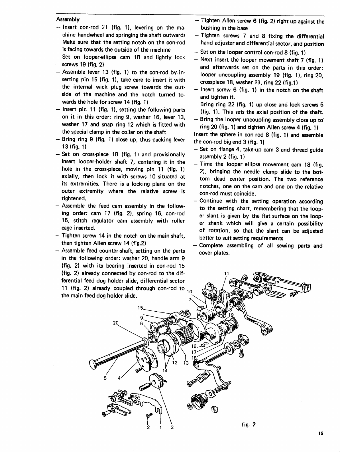
Assembly
-- Insert con-rod 21 (fig. 1), levering on the ma
chine handwheel
Make sure
is facing
towards
that
and
springing
the
setting
the
outsideofthe
the
shaft
notchonthe
machine
outwards
con-rod
—Set on looper-ellipse cam 18 and lightly lock
screws 19 (fig. 2)
—Assemble lever 13 (fig. 1) to
serting pin 15 (fig. 1),
the
internal wick plug
side
of
the
machine
wards
the
hole
for
take
and
screw 14 (fig. 1)
— Insert pin 11 (fig. 1), setting
the
con-rod by in
caretoinsert it
screw
towards
the
notch
the
following parts
the
turned
with
out
to
on it In this order: ring 9, washer 16, lever 13,
washer 17 and snap ring 12 which is fitted with
the
special clamp in
—Bring ring 9 (fig. 1) close up,
13 (fig. 1)
—
Set
on cross-piece 18 (fig. 1) and provisionally
the
collar on
the
shaft
thus
packing lever
insert looper-holder shaft 7, centering it in the
hole in
axially,
its extremities.
outer
tightened.
—Assemble
the
cross-piece, moving pin 11 (fig. 1)
then
lockitwith
extremity
the
There
where
feed cam assembly in
screws
is a locking plane on
the
10
relative
situated
screw
the
follow
the
ing order: cam 17 (fig. 2), spring 16, con-rod
15, stitch regulator cam assembly with roller
cage
inserted.
—Tighten screw 14 in
then
tighten Allen screw 14 (fig.2)
—Assemble feed
in
the
following
the
notchonthe
counter-shaft,
order:
washer
main
settingonthe
20,
handle arm 9
shaft,
parts
(fig. 2) with its bearing inserted in con-rod 15
(fig. 2) already connected by con-rod to the dif
ferential feed dog holder slide, differential sector
11 (fig. 2) already coupled through con-rod to
the
main feed dog
holder
slide.
—
Tighten
bushing in
—Tighten
hand
Allen
screw6(fig.2)rightupagainst
the
base
screws
adjuster and
7 and 8 fixing the differential
differential
sector, and
—Set on the looper control con-rod 8 (fig. 1)
—Next insert the looper movement shaft 7
and afterwards set on the parts in this order:
looper uncoupling assembly 19
(fig.
crosspiece 18, washer 23, ring 22 (fig.1)
— Insert screw 6 (fig. 1) in
and
tighten
Bring ring
(fig. 1). This sets
it.
22
(fig. 1) up close
the
the
notchonthe
and
lock
axial position of
—Bring the looper uncoupling assemblyclose up to
ring20
(fig.
1) and tighten
Allen
screw4
Insert the sphere in con-rod 8 (fig. 1) and assemble
the
con-rod big end 3 (fig. 1)
—Set on flange 4, take-up cam 3 and thread guide
assembly
2 (fig. 1)
—Time the looper ellipse movement cam 18 (fig.
2), bringing the needle clamp slide to the bot
at
is
tom
notches,
con-rod
dead
must
one
center
on
coincide.
position.
the
cam
and
The
two
oneonthe
—Continue with the setting operation according
to the setting chart, remembering
that
er slant is given by the flat surface on the loop
er shank which will give a certain possibility
of rotation, so that the slant can be adjusted
bettertosuit setting requirements
—Complete assembling of all sewing parts
cover
plates.
the
position
(fig.
1)
1), ring 20,
shaft
screws 5
the
shaft.
(fig.
1)
reference
relative
the loop
and
I®
15
Page 15

o
CO CO
LU LU LU LU
00
00
tu
CO
LU LU LU
00
CO CO
00
UJ
UJ UJ
CO CO
00
til
11?
00
00
til
\ii
CO
00
'M
CO
<
ooooo
ooooo
OOOT-t-
T^<6i«!.(ico
1-t-CM
ooo
ooo
ficneo
ooo
ooo
ooo
CO
d)
000000
000000
O O O
lA
CO
CM
in
T-
CM
CM
o
I
ooooo
999
9 9 9
OOO
909999
o o o o o o
o
(/}
O)
(/)
m
CM CM CM CM CM CM CM CM
111 lU UJ
op 9
o o o o ^
1-
O O O O CM
o o o o o
CO
00 00
CM C\J CM CM CM
2 S S 2 S
CM CO
£D
O
CO
tu
op Q
CO m
r>-
UJ
•«•
O D
CVJ CM
OOO
9 9 9
CM CM CM
CM CM CM CM CM CM
00
O CM CO
O CM CM
UJ
UJ
00
oo
UJ
00
UJ UJ UJ UJ UJ UJ
00 CO CO
CM CM CM
1-
•A
CM CM
O O
9
O O O
g g S o o o
g g g
O O O O O O
CM CM CM CM CM CM
2 H S
oT
CO
CO
CM
v:
Q 9 9
CM
CO
00
CM
CM CM
CO
CO
CO
UJ
O
u
Page 16

S.l
555-00
O)
O)
★
E50007-DC1/203-97
★
E50001-DC1/203-97
★
E50002-DC1/203-97
•
E50030-DC1/203-97
★
E50031-DC1/203-97
Needle
plate
surface
Ensure that the needle touches the front and rear needle guards when the point
of
the
primary
looper
enters
the
needle
groove.
Please Note;By pushing the needle at its lowest point against the needle guard,
the
thread
should
run
free.
17
Page 17

Needle
clampintopmost
Looper fully forward
position
MACHINE
E50001-SC1
E50003-SC1
E50001-DC1
E50002-DC1
ES0007-DC1
E50025-DC1
ES0026-CX:i
E50029-DC1
ES0031-DC1
E50101-DC1
E50102-DC1
E50104-DC1
ES0105-DC1
E51002-OC1 E53401-DC1
E51006-OC1
ES0109-OC1
E50020-DC1
ES0006-DC1
ES0030-OC1 ES2301-DC1
E50103-OC1
E52804-UC1
E50001-DC1/203-97
E50007-OC1/203-97
E50005-DC1
E50009-DC1
E50039-OC1
E50005-DC1/203-97
E50010-DC1
E50023-OC1
E50034^C1
E53007-DC1
ES0023-DM1 ES2812-DM1
E50033-OM1
ES0108-DM1
E52207-DM1
E54g01-DM1
E50050-DC1
CLASSES
E52813-DC1
E50601-DC1
E52202-DC1
ES2203-DC1
E52204-DC1
ES2302-DC1
E52802-OC1
E52809-CX:i
E52g01-DCl
E52902-DC1
E52905-DC1
E52906-DC1
E53402-DT1
E54001-SC1
E50138-DC1
E52201-DC1
E52806-UC1
E52807-DC1
E52812-DC1
E50010-SC1
ES3402-DM1
E53403-DM1
Looperatfarthest
Needle
plate
surface
B
A
X
10~
Y
9.9~
V
9.9~
X
9.4-
X
9,1-
y
9.9-
Y
9.9-
Y
9,9-
X
10.2-
Y
11.2-
X
10.7-
X
10.7-
X
10.5-
1.5-
1.5-
1.5-
1.5-
2,5-
1.5-
1.5-
1.5~
3-
1-
2.5-
2.5-
4.5-
c
2.3t2.5
2.3t2.7
2.3t2.7
2.3t2.7
2.5t2.8
1.8t2
2.3-
2.3-
2.6t3
2.3t2.5
2.5t3
2.5t3
2.6t3
3.5.74
3.5t4
3.5t4
3.7t4
3.5t4
E
D
3.5t4
5-
-
4-
8-
5t5.1
4.4-
4.2-
F
4.2-
4.2-
4.2-
4.2-
4-
4.2-
5—
5-
5-
- - - - -
- - - -
-
- - -
- - -
- -
-
- -
-
- -
- - - -
-
-
-
- - - C
rear
position
0.05
max
H
G
Do
4,
R
Fig. 1
-
-
-
-
-
-
-
-
-
-
-
Fig. 3
-
-
Fig. 3
Fig. 3
-
- Fig. 3
Fig. 3
-
Fig. 3
-
-
Fig. 3
Fig. 2
A
Fig. 3
A
Fig. 3
B
Fig. 3
Fig. 2
18
Page 18

qI]
Looper
fully
4^
forward
Needle
clampintopmosl
posillon
±z=x.A_
Fig. 1
Fig. 3
Fig. 2
Fig. 4
o
Looper at
♦
Needle
plate
surface
farthest
rear
position
MACHINE
E5002O-OM2
E50036-OM2 E50107-DM2
E50001-SM2
E5Q002-SM2
E50021-DM2
E50012-DC2
E50013-DC2
ES0018-DC2
E50041
E50001-SC2
E50014-OC2
E50015-OC2
E500164DC2
E50017-DC2 E52206-OC2
E50038-DC2
E5O044-OC2
E50t20-DC2
-002
CLASSES
E50003-SM2
E50in-DM2
E50047-DC2
E50106-DC2
E50002-SC2
E50032-DC2
E50045-DC2
E50t05-OC2
X
X
Y
X
X
X
X
X
X
A B
9,9-
9,9-
9-
9,0-
9t9,5
9.4-
9.4-
9,7-
9-
1.5-
t,5~
3.7f3.9
1,5-
1,5-
1,5-
1,5-
3-
1,5-
c
2.3t2,7
2,3^2,7
3,3t3,5
3.5-;-3.7
2,3t2,5
2.3^-2.4
2.7^2.9
1.8-I-2
6,1t6.4
2,3f2.53.If
2,2t2,4
2.5^-3
2,3^2,4
D E
a.5-
3,5
4f4,5
3-
6.5
F
-
-
-
- - -
3,5f3.7
444,5
-
- - -
- - -
- -
-
- -
3-
- - -
-
-
H
G
-
-
-
-
-
-
-
-
- - -
PD
A
B
-
8
A
-
A
A
4.
Fig. 1
Fig. 1
Pig. 2
Fig. 1
Fig. 1
Fig. 1
Fig. 3
Fig. 4
Fig. 1
Page 19

c5^
w
WORLDWIDE
Union
service
offices
sewing
Union
servicemen
serve
Whatever
Corporation
with
It is
COLUMBIA®
Special
most
machines.
Special
facilities
will
equipment
Special
your
him
today.
important
Corporation,
complete
M2lmionSp€cici£
Finest
Union
Union
Corporation
throughout
aid
you
Corporation
are
factory
needs
your
location,
representative
to
machines
line
Quality
Special
Special,
SALES
maintains
the
world.
In
the
selection
for
your
particular
representatives
trained
promptly
there
remember
are
thus
of
the
Corporation, 400 N. Franklin
GmbH,
is a
to
serve
that
also
products
offering
Finest
Schwabstrasse
and
and
Union
LEWIS®
the
Quality
of
are
you.
industry
33. D-7000
AND
sales
SERVICE
and
These
the
right
operation.
and
able
to
efficiently.
Special
Check
and
of
Union
the
sewing
K Industrial Sewing Equipment
Street,
Stuttgart
Sewing
Chicago, IL 60610, U.S.A.
1. West Germany.
Norcross,
Chicago,
Dallas,
Commerce,
New
Philadelphia,
Woburn,
Opa-Locka,
Montreal,
Toronto,
Catano,
Brussels,
Leicester,
Paris,
Stuttgart,W.Germany
Hong
other
all
partsotthe
Equipment
GA
IL
TX
CA
York,
NY
PA
MA
FL
Quebec
Ontario
Puerto
Belgium
England
France
Kong
Representatives
world
Rico
throughout
PrintedinU.S.A.
(462)
 Loading...