


INDUSTRIAL
FINE
ST
ST
YL
63
900A
63
900
6390OC
6390
6390OAL
ES
B
OD
Zwwm~
L E W I s® • C O L U M B I A®
SEWING
MACHINES
CLASS
CATALOG
63900
STREAMLINED
No.
126M
Second
Edition
HIGH
LOCKSTITCH
SPEED
NEEDLE
MACHINES
UNION SPECIAL
CHICAGO
FEED
CORPORATION

Catalog
No.
INSTRUCTIONS
FOR
126
M
ADJUSTING
LIST
Streamlined
63900
63900
Second
AND
OF
CLASS
Needle
Styles
A
B
63900
OPERATING
PARTS
63900
Feed
Lockstitch
63900
63900
AL
Edition
C
D
Copyright
1963
&
1970
by
Union
Rights
Special
Reserved
Corporation
in
All
Countries
UNION SPECIAL CORPORATION
INDUSTRIAL
Printed
SEWING
CHICAGO
in
U.S.A.
2
MACHINES
August,
1978
The
predominant
ines
in
the
world.
are a decided
insuring
1.
2.
complete
A
few
of
QUICK
The
box
STREAMLINED
INSTALLATION
average
to
production
idea
The
achievement
interchangeability.
the
outstanding
installation
DESIGN
behind
new
high
along
sewing.
Union
speed.
these
features
time
if
installation
FOREWORD
Special,
streamlined
lines.
are:
required
will
is
to
build
Class
Parts
instructions
be
are
about
the
63900
made
10
are
best
industrial
lockstitchmachines
to
precision
minutes
followed.
from
mach-
gauges.
packing
Pleasing
ruggedness.
is
more
3.
SIMPLIFIED.
Lubrication
for
system
reservoir,
tenance.
4.
RAPID
Precision
oiling
higher
5.
PUSH
For
dial
the
It
is
which
SPECIAL
data.
enables
in
appearance,
freedom
restful
OILING
of
these
trouble
BUTTON
quick,
is
needle
the
machines.
free
provided
sealed
ACCELERATION
methods
system.
productive
easy
marked
feed.
constant
customers
from
to
operator's
machines
operation.
long
makes
CONTROL
adjustment
in
stitch
aim
The
against
in
the
rates
of
to
following
hook
possible
this
functional
difficult-to-
eye.
is
A
completely
life.
lint
manufacture
and
lower
of
the
lengths.
Union
procure
Special
design
clean
automatic.
adjustable,
A
single,
and
dust.
of
top
operating
costs.
stitch
plus a readily
all
pages
length, a large,
to
furnish
possible
discuss
recesses.
Oil
large
reduces
all
parts,
speed
accessible
concisely
advantages
valuable
provides
is
supplied
double
capacity,
to a minimum
coupled
greater
New
almost
easy-to-
prepared
from
Adjusting
stability
neutral
to
filtered
accurately
with
instantaneous
nieans
the
all
read
and
moving
oiling
an
for
use
taupe
information
finish
parts
hook
oiling
gauged
main-
advanced
indicator
adjusting
of
UNION
Operating
and
for
Adjusting
attention
tions
name,
combinations.
for a wide
are
anxious
ments.
to
are
Exploded
follow
Union
many
used
range
Special
to
Instructions
parts
to
pinpoint
views,
the
with
of
cooperate
together
Instructions,
recommendations
operations.
representatives.
which
areas
in
for
Mechanics.
must
under
with
after
planning
meet
to
exacting
discussion.
explanations
which,
experience
be
found
and
make
covering
conditional
as
is
shown a collection
has
in
all
leading
estimates
UNION SPECIAL CORPORATION
3
Styles
to
quantity,
prompted
tailored
Engineering
in
this
adjustments.
us
manufacturing
part
of
to
to
catalog.
number
sewing
recommend
your
Department
call
Illustra-
and
part
centers,
require-
.
Each
machine.
have
63900
UNION
Style
one
or
A".
SpecialStylenumbers
in a standard
63900
AZ".
SPECIAL
numbers
more
machine,
letters
a
IDENTIFICATION
machine
are
classified
suffixed,
11211
is
is
but
contain
suffixed
identified
as
never
the
to
OF
MACHINES
by a Style
standard
contain
letter"Z".
the
Standard
and
When
number
special.
the
letter
only
Style
on a name
Standard
11211
minor
number.
Style
•
Example:
changes
Example:
plate
numbers
are
on
the
"Style
made
"Style
Styles
differs
This
It
can
Reference
position
from
also
while
of
machines
the
catalog
be
applied
to
direction,
seated
operator.
High
Speed
Medium
Stitch
Reservoir
Control,
and
Needle
Upper
Streamlined
and
Heavy
Regulator,
Enclosed
Needle
Bar
Shaft,
Maximum
Driving
63900 A Equipped
operations
183
GXS
stitches
5500
R.P.M.
on
or
per
style
applies
Duty,
Slotted
Automatic
Bearing
with
light
183
GYS
inch,
similar
number,
APPLICATION
specifically
with
discretion
such
as
right,
at
the
machine.
Long
Arm
Drop
Segment -for
Adjustable
Link,
Work
disc
and
Feed
Space
tension
medium
needles.
thread
size,
in
construction
in
that
to
the
to
left,
STYLES
Needle
Feed,
Rotary
Adjusting
Lubricating
Feed
Timing
to
Right
for
weight
Seam
needle
are
it
contains
OF
CATALOG
Standard
some
front,
Special
back,
Operating
OF
MACHINES
Feed
Lockstitch
Hook,
Needle
System,
Eccentric,
on
Lower
of
Needle
needle
thread.
work.
specification
type
and
grouped
no
letters.
Styles
Styles
etc.,
direction
Horizontal
Feed,
Head
Oil
Needle
Main
Ba:r
For
1 9 /
64
30 l -SSa-1.
size.
under a Class
Example:
of
machines
of
machines
are
given
of
handwheel
Machines,
Hook
Stitch
Length
Siphon,
Bearings
Shaft,
11
1/8
Needle
Inches.
miscellaneous
inch
needle
Specify
Maximum
recommended
number,
"Class
as
listed
in
from
the
is
One
Needle,
Shaft,
Push
Indicator,
Adjustable
for
Take-up
Feed
plain
bar
travel.
Style
which
63900
herein.
this
class.
operator's
toward
Light,
Button
One
Hook
Lever
Timing
seaming
Type
number,
speed
11
the
Oil
on
•
63900 B Equipped
operations
Type
180
stitches
5500
R.P.M.
on
GXS
per
63900 C Equipped
operations
183
GXS
stitches
5500
R.P.M.
on
or
per
63900 D Equipped
operations
Type
stitches
63900
feed
5500
AL
180
R.P.M.
driving
on
GXS
per
Same
with
disc
medium
or
180
GYS
inch,
thread
with a rotary
light
183
inch,
and
GYS
thread
with a rotary
medium
or
180
GYS
inch,
as
thread
Style
63900 C except
shaft.
tension
and
medium
needles.
size,
tension
medium
needles.
size,
tension
and
medium
needles.
size,
for
heavy
Seam
needle
for
weight
Seam
needle
heavy
Seam
needle
needle
weight
specification
type
needle
work. 1 9/64
specification
type
for
needle
weight
specification
type
fitted
with
4
thread.
work. 1 13/
and
size.
thread.
301 -
and
size.
thread.
work. 1 13/64
and
size.
a.
025
For
miscellaneous
64
301-SSa-1.
Maximum
For
miscellaneous
inch
SSa-
Maximum
For
miscellaneous
301-SSa-1.
Maximum
inch
eccentric
inch
Specify
recommended
needle
1.
Specify
recommended
inch
Specify
recommended
plain
needle
Style
plain
bar
Style
plain
needle
Style
(.
050
seaming
bar
number,
seaming
travel.
number,
seaming
bar
number,
inch
travel.
speed
Type
speed
travel.
speed
throw)
NOTE:
to
throat
For
the
number
Pages 6 and
plate
and
7.
feed
The
necessary
number
dog.
Specify
to
complete
the
Styling
indicates a certain
the
needle
hole
NEEDLES
of
sewing
size
if
these
63900
machines,
combination -presser
more
than
one
is
available
refer
foot
.
Each
number
number,
in
thousandths
represent
by
Union
Needle
Type
and
Type
180
180
183
183
183
sizes
No.
GXS
GYS
GXS
GYS
UNION
denotes
stamped
the
Special.
Type
GXS
available
Round
wide
sizes
150/060.
Round
wide
075/029,
Round
groove,
plated
Round
groove,
sizes
SPECIAL
the
kind
of
on
the
needle
of
an
inch
across
complete
180
or
183
GXSor
GYS
are
symbol
listed
shank,
angle
groove,
075/029,
shank,
angle
080/032,
shank,
wide
- s
izes
shank,
wide
075/029, 080/032,
needle
shank,
180
is
recommended
has
point,
shank,
the
eye.
which
GYS
denotes
is
isrecommendedforStyles
below.
round
point,
struck
080/032,
round
groove,
round
angle
round
angle
point,
struck
090/036,
point,
groove,
065/025, 075/029,
point,
groove,
090/036, 100/040,
both a type
length,
groove,
the
Collectively,
given
for
on
the
Styles
Description
lockstitch,
groove,
090/036,
lockstitch
deep
, s
groove,
100/040,
lockstitch,
struck
groove,
080/032,
lockstitch,
struck
number
finish
largest
the
label
63900
and
short
spot,
100/040,
hort
deep
110/044,
extra
extra
groove,
and a size
diameter
type
number
of
all
A, C and
Sizes
length,
ball
110/044,
length,
spot,
125/049,
short
deep
spot,
090/036,
short
deep
110/044.
and
other
of
needles
63900
AL.
ball
point,
ball
chromium
length,
ball
length,
spot,
number.
details.
the
blade
and
the
packaged
Band
D,
Their
eye,
single
chromium
125/049,
eye,
single
plated -sizes
140/054,
ball
point,
100/040,
ball
chromium
The
type
The
size
measured
size
number
and
sold
and
needle
description
groove
plated
140/054
groove
150/060
eye,
single
chromium
110/044.
eye,
single
plated
,
-
,
,
w
-
To
needle,
complete
Selection
Thread
The
the
thread
of
the
needle
The
thread.
may
dictate
Cotton
Size
0
30
36
40
50
60
70
80
90
100
have
or
the
order
should
strength
employed.
following
The
the
Thread
needle
type
would
of
proper
pass
requirement
employed.
table
choice,
selection
orders
and
read:
needle
freely
SELECTING
The
shows
however,
promptly
size
number
11
1000
size
through
of
the
the
quality
the
should
of a needle
and
should
Needles,
stiould
needle
THE
seam
of
the
preferred
give
size
Mercerized
accurately
be
forwarded.
Type
be
eye
SIZE
180
determined
in
order
OF
produced
work
desired
size
consideration
slightly
larger
Thread
Size
B
A
A
0
00
000
0000
0000
filled,
GXS,
THE
is
of
needle
an
empty
Use
Size
080/032
by
the
size
to
produce a good
NEEDLE
largely
is
largely
dependent
for a given
to
factors
or
smaller
referred
package, a sample
description
of
11
•
the
thread
stitch
upon
dependent
upon
size
to
above,
than
the
size
Needle
150/060
140/054
125/049
110/044
110 / 044
100/040
090/036
080/032
080/032
075/029
on
label.
used.
formation.
the
size
the
size
and
kind
which
specified.
Size
to
150/060
to
140/054
to
125/049
to
12
5 /
04
to
110/044
to
100/040
to
090/036
to
090/036
to
080/032
A
of
of
9
5
**
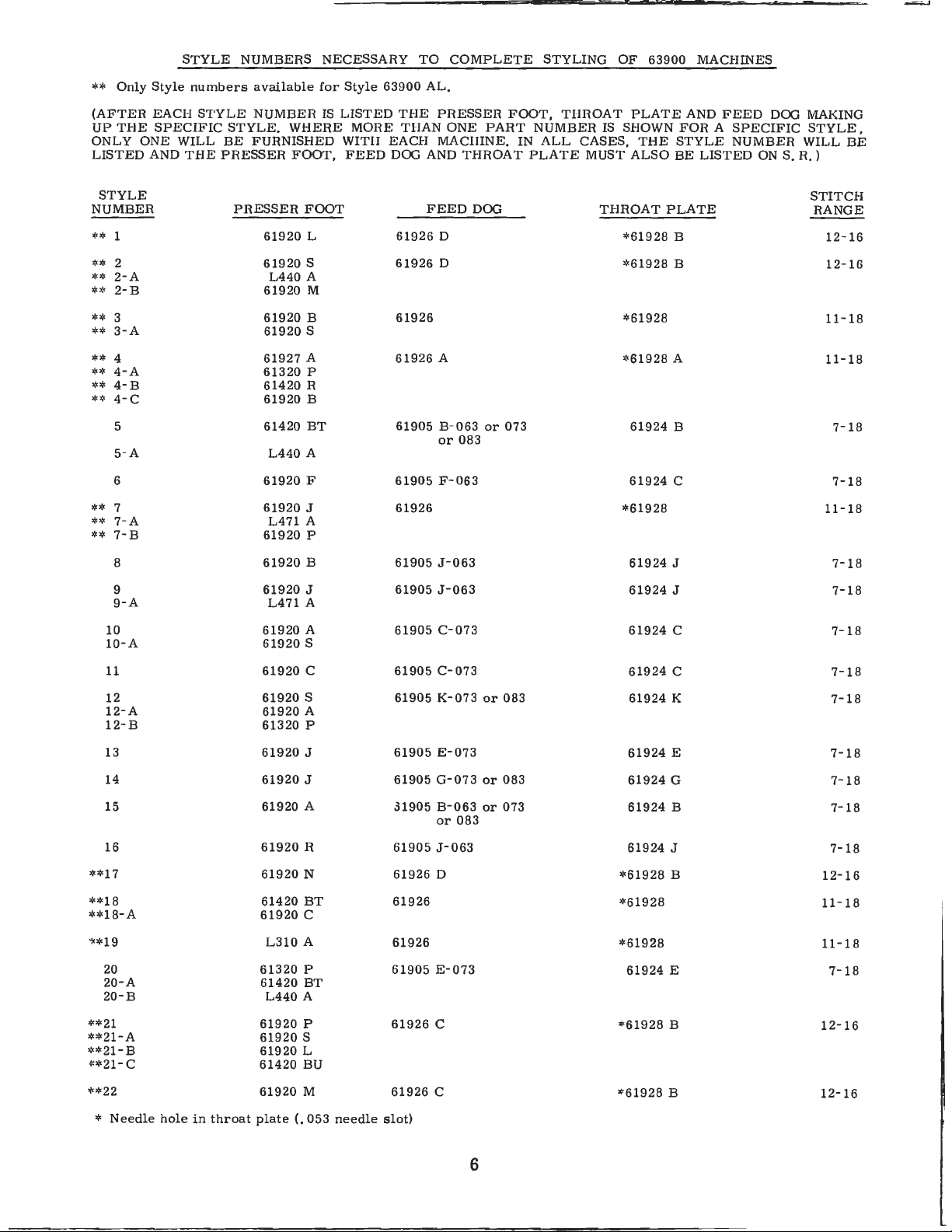
Only
Style
STYLE
numbers
NUMBERS
available
NECESSARY
for
Style
63900
TO
COMPLETE
AL.
STYLING
OF
63900
MACHINES
(AFTER
UP
THE
ONLY
LISTED
NUMBER
**
**
**
**
**
**
**
**
**
**
**
**
**
ONE
STYLE
1
2
2- A
2- B
3
3- A
4
4-A
4- B
4-C
5
5- A
6
7
7-A
7-B
8
EACH
STYLE
SPECIFIC
WILL
AND
THE
NUMBER
STYLE.
BE
FURNISHED
PRESSER
PRESSER
61920
61920
L440
61920
61920
61920
61927
61320
61420
61920
61420
L440
61920
61920
L471
61920
61920
IS
WHERE
FOOT,
FOOT
L
S
A
M
B
S
A
P
R
B
BT
A
F
J
A
P
B
LISTED
MORE
WITH
FEED
THE
PRESSER
THAN
EACH
DOG AND
61926
61926
61926
61926
61905 B-063
61905
61926
61905
ONE
MACIIINE.
FEED
D
D
A
or
F-063
J-063
PART
THROAT
DOG
or
083
FOOT,
NUMBER
IN
PLATE
073
THROAT
ALL
IS SHOWN
CASES,
MUST
THROAT
PLATE
THE
ALSO
*61928
*61928
*61928
*61928
61924
61924
*61928
61924
AND
FEED
FOR A SPECIFIC
STYLE
BE
PLATE
B
B
A
B
C
J
NUMBER
LISTED
ON
DOG MAKING
STYLE,
WILL
S.
R.)
BE
STITCH
RANGE
12-16
12-16
11-18
11-18
7-18
7-18
11-18
7-18
9
9-A
10
10-A
11
12
12-A
12-B
13
14
15
16
**17
**18
**18-A
1<*19
20
20-A
20-B
**21
**21-A
**21-B
i:*21-C
61920
L471
61920
61920
61920
61920
61920
61320
61920
61920
61920
61920
61920
61420
61920
L310
61320
61420
L440
61920
61920
61920
61420
J
A
A
S
C
S
A
P
J
J
A
R
N
BT
C
A
P
BT
A
P
S
L
BU
61905
61905
61905
61905
61905
61905
31905
61905
61926
61926
61926
61905
61926
J-063
C-073
C-073
K-073
E-073
G-073
B-063
or
083
J-063
D
E-073
C
or
or
or
083
083
073
61924
61924
61924
61924
61924
61924
61924
61924
*61928
*61928
*61928
61924
*
61928
J
C
C
K
E
G
B
J
B
E
B
7-18
7-18
7-
7-18
7-18
7-
18
7-18
7-18
12-16
11-18
11-18
7-
18
12-16
18
61920
(.
M
053
needle
61926
slot)
C
**22
*
Needle
hole
in
throat
plate
6
61928
B
12-16
STYLE
NUMBER
23
2:3
- A
PRESSER
61420
61920
FOOT
BU
S
61926
FEED
H
DOG
THROAT
61928
#
I-1
PLATE
or
II-
050
STITCH
RANGE
9-18
24
25
26
,;,, 27
28
28
- A
29
*'~
30
*''30- A
*~'
31
**
31- A
•!<*
32
,,,,3 3
,,,,
34
**
35
·~~'
36
**36- A
,,,:,3 7
38
61420
61420
BT
61920
B
61920
B
61920
B
61920
A
61420
BT
61920
L
61920
A
61420
AP
61920
M
61920
R
61920 1\1
61920
B
61920
1\1
61420
BV
61420
BY
61420
BT
61920
L
61D05 K-073
M-
F
C
D
J -
063
C
J -
063
E
T
063
6190
6190 C-073
61926
61905 E-073
61905
61926
61926
61926
61926
61926
61926
61926
61926
61905
or
083
61924
61924
61924
61928
*
61924
61924
••
6192
*
6192
*
61928
""
61928
61928
*
''
61928
61928
•'
61928
*
61924
I<
E 7- 18
C 7- 1 8
B
E
J
8
8
C
C
B
B
J
12-16
11
11
11
12-16
1112-16
12-
12-16
7-
18
7- 18
7· 18
-18
- 18
- 18
18
16
7-18
*••39
40
**
76
*~'77
78
79
80
81
82
**
83
**
84
85
86
86
- A
"'
*88
·~•!<8
9
**9
0
,,,,91
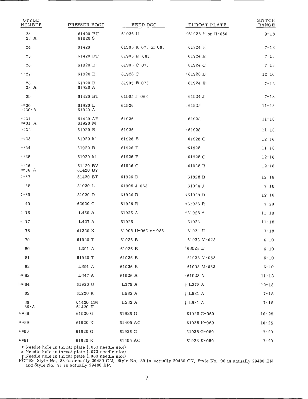
* Needle hole
#
Needle
t
Needle
NOTE:
and
hole
hole
Style
Style No.
in
in
in
No.
throat
throat
throat
88
91
plate
plate(. 073
plate
is
actually
is
actually
61920
63920
L460
L427
61220
61920
L391
61920
L391
L347
61920
61220
61420
61420
61920
61920
61920
61920
D
C
A
A
I<
T
A
T
A
A
U
K
CM
H
G
K
G
K
{.
053
(.
063
29480
29480
61926
61926
61926
61!)26
61905
61926
61926
61926
61926
61926
L582
L582
61926
61405
61926
61405 AC
needle
needle
needle slot)
CM,
EP.
slo
slot)
Style
L379
t)
A
A
A
A
G
AC
G
No.
D
R
A
II-063
B
B
B
B
89
or
is
083
actually
29480
*61928 B
•!<
619
28
R
1D
28
*6
*61928
#
••
t
t
t
A
61924 H
61928 M-073
63928
E
61928
1\1-053 661928 1\161028
A
L378
A
L581
A
L581
A
61928
G-060
61928
K-060
61928 G-050
61928 K-050
CN,
Style No.
053
90
is
act
ually
11-18
12-18
10-25
10-25
29480
12-16
7-20
11-18
11-
18
7-18
6-
10
10
6-
10
6-10
18
7·
7-
18
7-
20
7-
20
EN
7
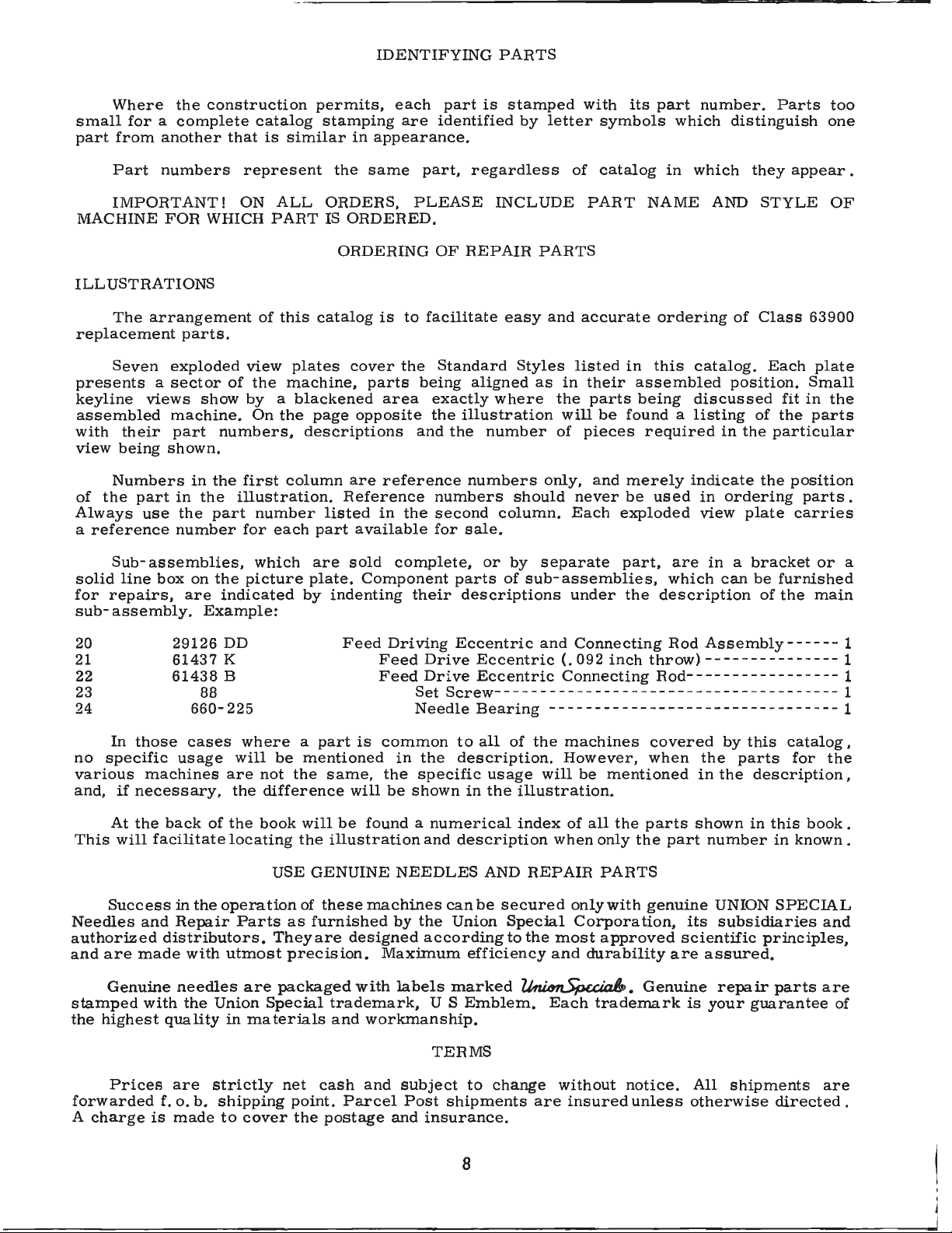
IDENTIFYING
PARTS
Where
small
part
MACHINE
ILLUSTRATIONS
replacement
presents a sector
keyline
assembled
with
view
of
Always
a
for a complete
from
Part
IMPORTANT!
The
Seven
their
being
Numbers
the
reference
the
another
numbers
FOR
arrangement
parts.
exploded
views
part
use
show by a blackened
machine.
part
shown.
in
in
the
the
number
construction
catalog
that
is
similar
represent
ON
ALL
WHICH
numbers,
the
part
PART
of
this
view
of
the
machine,
On
the
first
column
illustration.
number
for
each
permits,
stamping
in
the
ORDERS,
IS
ORDERED.
ORDERING
catalog
plates
cover
page
opposite
descriptions
are
Reference
listed
part
available
each
are
identified
appearance.
same
parts
part,
PLEASE
is
to
facilitate
the
being
area
reference
in
exactly
the
and
numbers
the
for
OF
Standard
second
part
is
regardless
INCLUDE
REPAIR
aligned
where
illustration
the
number
numbers
column.
sale.
stamped
by
letter
PARTS
easy
and
Styles
as
only,
should
with
of
accurate
listed
in
the
will
of
pieces
never
Each
its
symbols
catalog
PART
their
parts
be
and
NAME
in
assembled
being
found a listing
required
merely
be
exploded
part
number.
which
in
which
ordering
this
catalog.
discussed
indicate
used
in
view
distinguish
they
AND
STYLE
of
Class
position.
of
in
the
the
ordering
plate
Parts
appear.
63900
Each
plate
Small
fit
in
the
parts
particular
position
parts.
carries
too
one
OF
the
Sub-
solid
line
for
repairs,
sub-
assembly.
20
21
22
23
24
In
those
no
specific
various
and,
if
necessary,
At
the
This
will
Success
Needles
authorized
and
are
made
Genuine
stamped
the
highest
assemblies,
box
on
are
Example:
29126
61437
61438
88
660-225
cases
usage
machines
back
facilitate
in
the
and
Repair
distributors.
with
needles
with
the
quality
which
the
picture
indicated
DD
K
B
where a part
will
are
not
the
difference
of
the
book
locating
USE
operation
Parts
They
utmost
are
Union
in
materials
Special
are
plate.
by
indenting
be
mentioned
the
same,
will
the
illustration
GENUINE
of
these
as
furnished
are
precision.
packaged
trademark,
and
sold
complete,
Component
their
Feed
Driving
Feed
Feed Dri
is
will
be
found a numerical
machines
designed
with
workmanship.
Drive
Set
Needle
common
in
the
the
specific
be
shown
and
NEEDLES
by
the
according
Maximum
labels
U S
or
by
parts
Eccentric
ve
Screw-
can
Union
marked
of
descriptions
Eccentric(.
Eccentric
- - - - - - - - -- - - - - -- - - - - - - - - -- - - - - - - - -- -- 1
Bearing
to
all
of
description.
usage
in
the
description
AND
be
secured
Special
to
efficiency
Emblem.
separate
sub-assemblies,
under
and
Connecting
Connecting
- - -- - - - - -- - - - - -- - - - - - - - - - -- - - - - - 1
the
machines
However,
will
illustration.
index
of
when
REPAIR
the
most
and
~.
Each
only
Corporation,
part,
the
092
inch
be
mentioned
all
the
only
PARTS
with
approved
durability
trademark
are
in a bracket
which
description
Rod
throw)---------------
Rod-
covered
when
parts
the
part
genuine
are
Genuine
can
Assembly------
- - - - - - - - - - - - - - - - 1
by
this
the
parts
in
the
shown
its
scientific
is
in
number
UNION
subsidiaries
assured.
repair
your
guarantee
be
furnished
of
the
description,
this
in
SPECIAL
principles,
parts
or
main
catalog,
for
the
book
known.
and
are
of
a
1
1
.
TERMS
Prices
forwarded
A
charge
f. o.
is
are
b.
made
strictly
shipping
to
cover
net
point.
the
cash
Parcel
postage
and
subject
Post
and
insurance.
to
change
shipments
8
without
are
insured
notice.
unless
All
shipments
otherwise
are
directed.
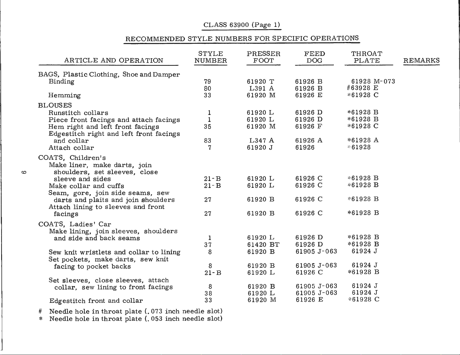
CLASS
63900
(Page
1)
co
ARTICLE
BAGS,
Plastic
Binding
Hemming
BLOUSES
Runstitch
Piece
Hem
right
Edgestitch
and
Attach
COATS,
Make
shoulders,
sleeve
Make
Seam,
darts
Attach
facings
Clothing,
collars
front
facings
and
right
collar
collar
Children's
liner,
collar
and
make
sides
and
gore,
and
plaits
lining
AND
left
set
join
to
RECOMMENDED
OPERATION
Shoe
and
front
and
left
darts,
sleeves,
cuffs
side
seams,
and
join
sleeves
and
attach
facings
front
JOm
close
shoulders
and
front
Damper
facings
facings
sew
STYLE
STYLE
NUMBER
79
80
33
1
1
35
83
7
21-B
21- B
27
27
NUMBERS
PRESSER
61920
61920
61920
61920
61920
61920
61920
61920
61920
61920
FOR
FOOT
L391
L347
SPECIFIC
T
A
M
L
L
M
A
J
L
L
B
B
OPERATIONS
FEED
DOG
61926
61926
61926
61926
61926
61926
61926
B
B
E
D *
D
F
A *
61926
61926
61926
61926
61926
C
C
C
C
T
HROAT
PLATE
61928
63928
#
:,,'<
61928
61928
61928
*
"'"61928
61928
*
61928
61928
*
""
61928
61928
*
*61928
REMARKS
M-073
E
C
B
B
C
A
B
B
B
B
COATS,
Make
and
Ladies'
lining,
side
and
Car
join
back
sleeves,
seams
shoulders
1
37
Sew
Set
facing
knit
wristlets
pockets,
to
make
pocket
and
darts,
backs
collar
sew
to
knit
lining
8
8
21-B
Set
sleeves,
collar,
sew
close
lining
sleeves,
to
front
attach
facings
8
38
Edgestitch
Needle
#
Needle
*
hole
hole
front
in
in
and
throat
throat
collar
plate
plate
(.
(.
073
053
inch
inch
needle
needle
33
slot)
slot)
61920
61420
61920
61920
61920
61920
61920
61920
L
BT
B
B
L
B
L
M
61926
61926
61905
61905
61926
61905
61905
61926
D
D
J-063
J-063
C
J-063
J -
063
E
""'
61928
"'"
61928
61924
61924
61928
*
61924
61924
""'
61928
B
B
J
J
B
J
J
C
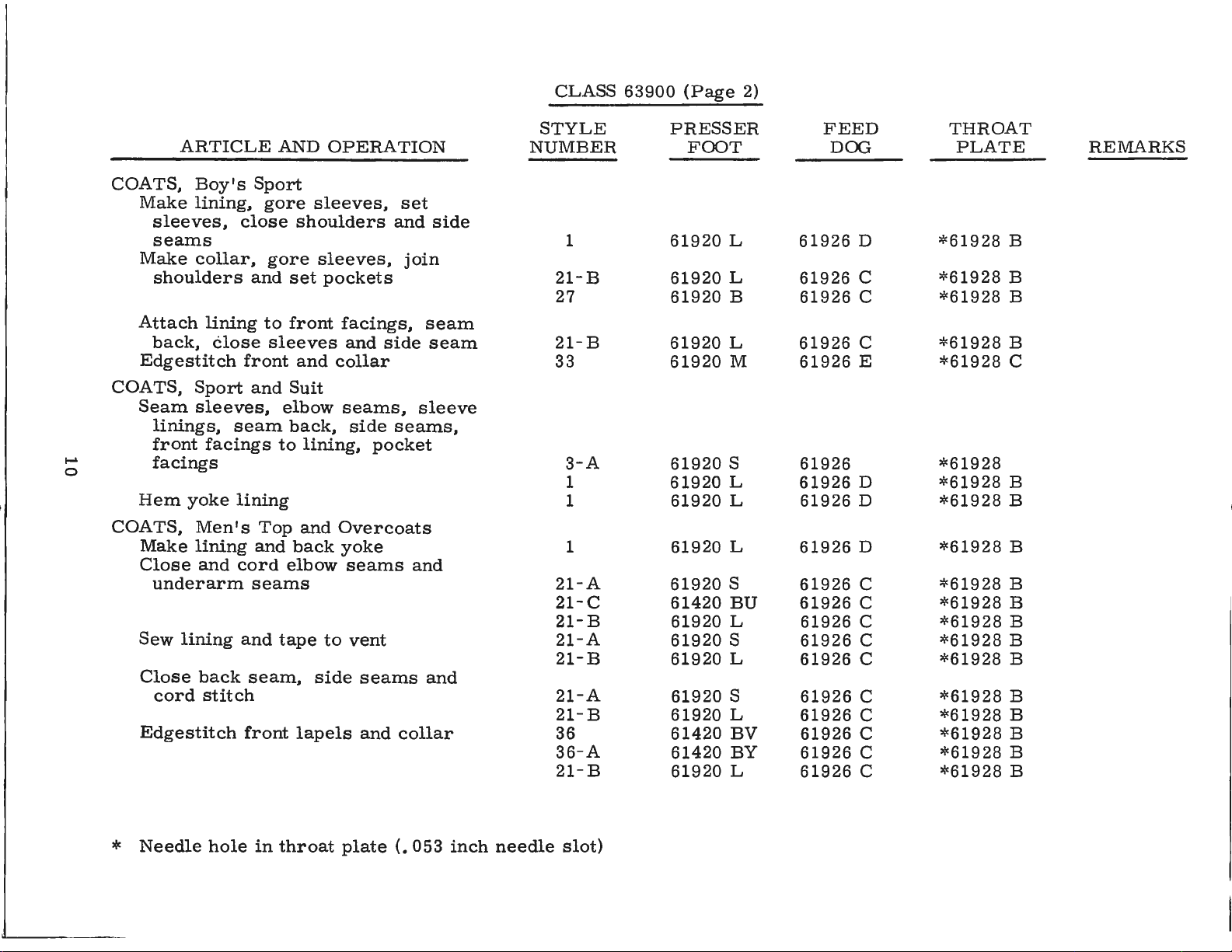
CLASS
63900
(Page
2)
1--'
0
COATS,
Make
sleeves,
seams
Make
shoulders
Attach
back,
Edgestitch
COATS,
Seam
linings,
front
facings
Hem
COATS,
Make
Close
underarm
Sew
Close
cord
Edgestitch
ARTICLE
Boy's
Sport
lining,
close
collar,
and
lining
close
front
Sport
and
sleeves,
seam
facings
yoke
lining
Men's
lining
and
cord
seams
lining
back
and
seam,
stitch
front
AND
gore
gore
set
to
front
sleeves
Suit
elbow
back,
to
Top
and
elbow
tape
OPERATION
sleeves,
shoulders
sleeves,
pockets
facings,
and
and
collar
seams,
side
lining,
and
Overcoats
back
yoke
seams
to
vent
side
seams
lapels
and
set
and
join
side
sleeve
seams,
pocket
and
collar
side
seam
seam
and
STYLE
NUMBER
1
21-B
27
21-B
33
3-A
1
1
1
21-A
21-C
21-B
21-A
21-B
21-A
21-B
36
36-A
21-B
PRESSER
FOOT
61920
61920
61920
61920
61920
61920
61920
61920
61920
61920
61420
61920
61920
61920
61920
61920
61420
61420
61920
L
L
B
L
M
S
L
L
L
S
BU
L
S
L
S
L
BV
BY
L
FEED
DOG
61926
61926
61926
61926
61926
61926
61926
61926
61926
61926
61926
61926
61926
61926
61926
61926
61926
61926
61926
D
C
C
C
E
D
D
D
C
C
C
C
C
C
C
C
C
C
THROAT
PLATE
*61928
*61928
*61928
*61928
*61928
*61928
*61928
*61928
*61928
*61928
*61928
*61928
*61928
*61928
*61928
*61928
*61928
*61928
*61928
REMARKS
B
B
B
B
C
B
B
B
B
B
B
B
B
B
B
B
B
B
*
Needle
hole
in
throat
plate
(.
053
inch
needle
slot)
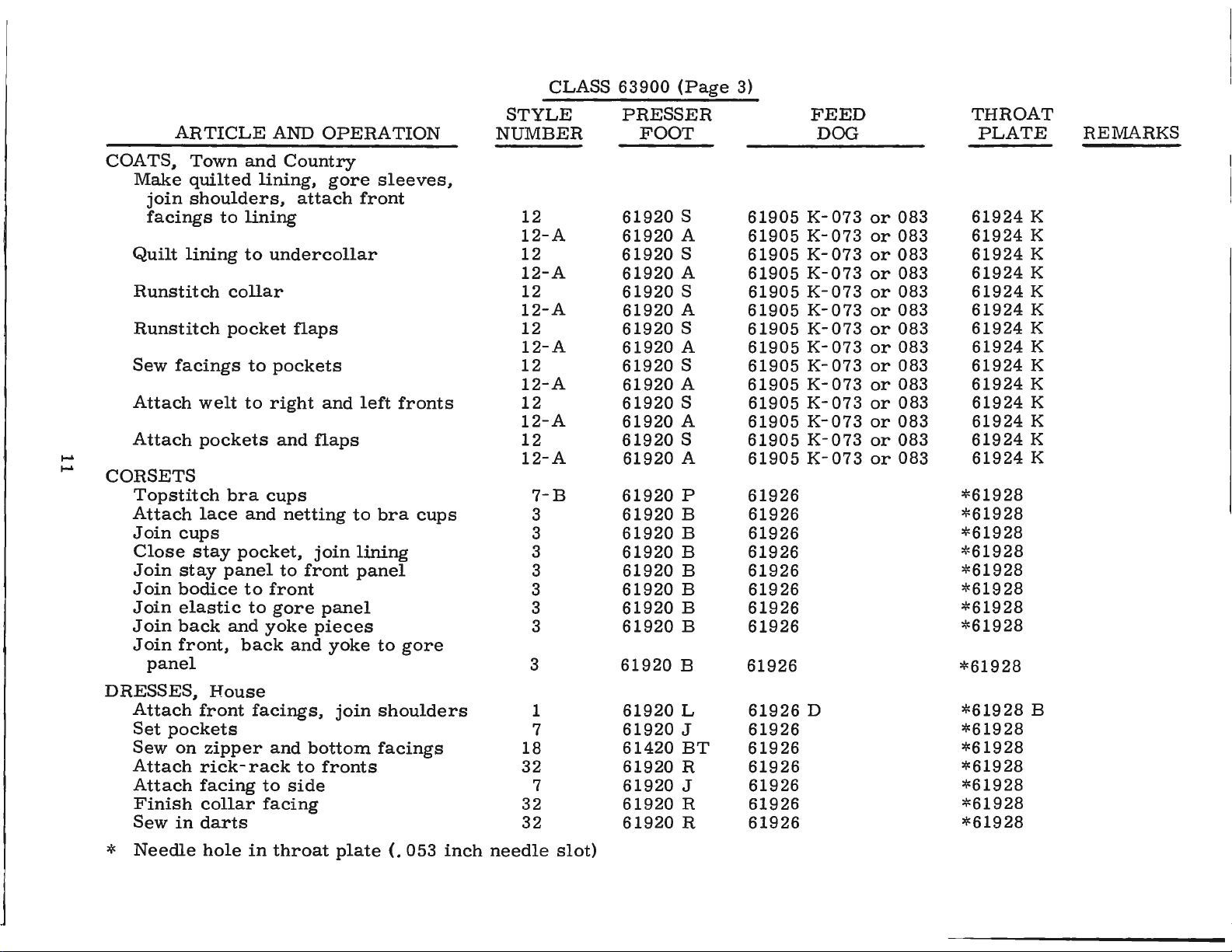
CLASS
63900
(Page
3)
.....
.....
ARTICLE
COATS,
Make
join
facings
Quilt
Runstitch
Runstitch
Sew
Attach
Attach
CORSETS
Topstitch
Attach
Join
Close
Join
Join
Join
Join
Join
DRESSES,
Attach
Set
Sew
Attach
Attach
Finish
Sew
lining
facings
cups
stay
bodice
elastic
back
front,
panel
pockets
on
in
Town
quilted
shoulders,
welt
stay
and
lining,
to
lining
to
collar
pocket
to
to
pockets
bra
lace
and
pocket,
panel
to
to
and
back
House
front
zipper
rick-rack
facing
collar
darts
facings,
to
facing
AND
undercollar
pockets
right
cups
front
gore
yoke
and
OPERATION
Country
gore
attach
flaps
and
and
flaps
netting
join
to
front
panel
pieces
and
yoke
bottom
to
fronts
side
join
sleeves,
front
left
to
bra
lining
panel
to
shoulders
facings
fronts
cups
gore
STYLE
NUMBER
12
12-A
12
12-A
12
12-A
12
12-A
12
12-A
12
12-A
12
12-A
7-B
3
3
3
3
3
3
3
3
1
7
18
32
7
32
32
PRESSER
FOOT
61920
61920
61920
61920
61920
61920
61920
61920
61920
61920
61920
61920
61920
61920
61920
61920
61920
61920
61920
61920
61920
61920
61920
61920
61920
61420
61920
61920
61920
61920
S
A
S
A
S
A
S
A
S
A
S
A
S
A
P
B
B
B
B
B
B
B
B
L
J
BT
R
J
R
R
61905
61905
61905
61905
61905
61905
61905
61905
61905
61905
61905
61905
61905
61905
61926
61926
61926
61926
61926
61926
61926
61926
61926
61926
61926
61926
61926
61926
61926
61926
FEED
DOG
K-073
K-073
K-073
K-073
K-073
K-073
K-073
K-073
K-073
K-073
K-073
K-073
K-073
K-073
D
or
or
or
or
or
or
or
or
or
or
or
or
or
or
083
083
083
083
083
083
083
083
083
083
083
083
083
083
THROAT
PLATE
61924
61924
61924
61924
61924
61924
61924
61924
61924
61924
61924
61924
61924
61924
*61928
*61928
*61928
*61928
*61928
*61928
*61928
*61928
*61928
*61928
*61928
*61928
*61928
*61928
*61928
*61928
REMARKS
K
K
K
K
K
K
K
K
K
K
K
K
K
K
B
*
Needle
hole
in
throat
plate
(.
053
inch
need
le
slot)
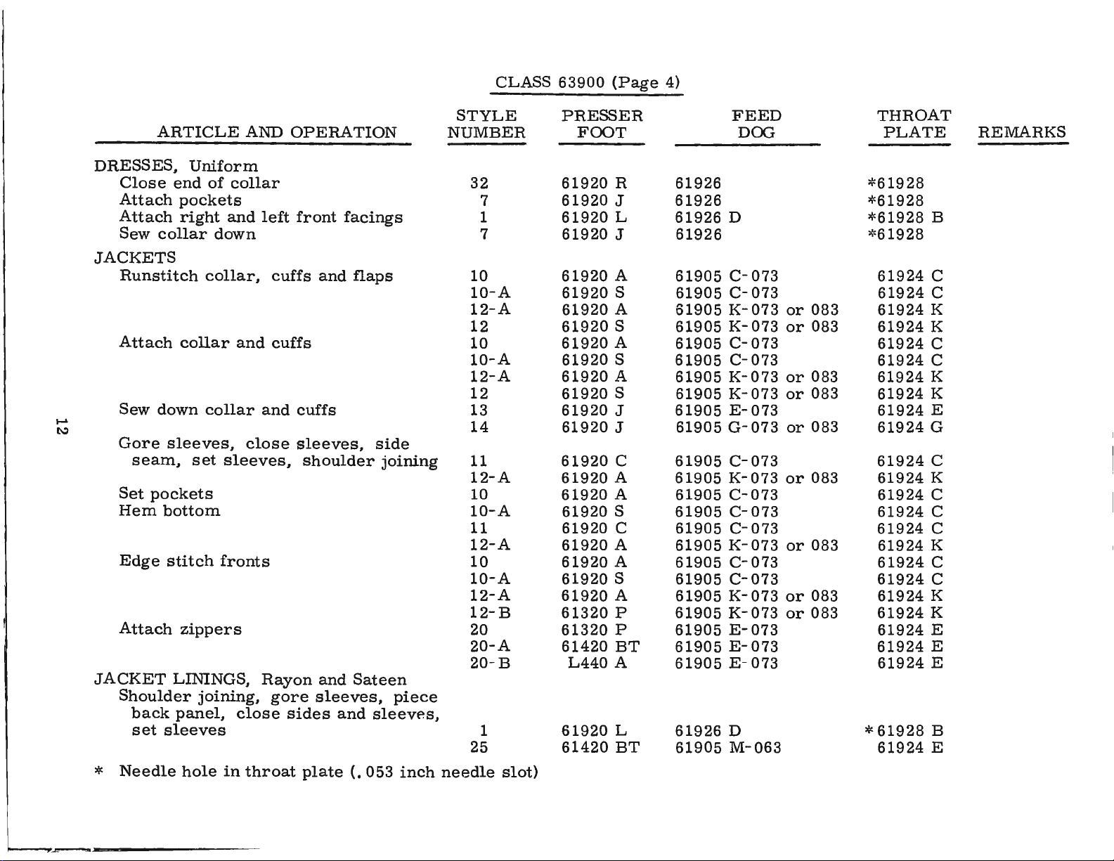
CLASS
63900
(Page
4)
I.'-'
""""
ARTICLE
DRESSES,
Close
Attach
Attach
Sew
collar
JACKETS
Runstitch
Attach
Sew
down
Gore
seam,
Set
pockets
Hem
Edge
Attach
JACKET
Shoulder
back
set
bottom
stitch
sleeves
Uniform
end
of
pockets
right
collar
sleeves,
zippers
LININGS,
panel,
and
down
collar,
collar
set
sleeves,
fronts
joining,
AND
collar
left
and
and
close
Rayon
close
OPERATION
front
cuffs
cuffs
gore
and
cuffs
sleeves,
shoulder
and
sleeves,
sides
and
facings
flaps
side
joining
Sateen
sleevP.s,
piece
STYLE
NUMBER
32
7
1
7
10
10-A
12-A
12
10
10-A
12-A
12
13
14
11
12-A
10
10-A
11
12-A
10
10-A
12-A
12-B
20
20-A
20 - B
1
25
PRESSER
FOOT
61920
61920
61920
61920
61920
61920
61920
61920
61920
61920
61920
61920
61920
61920
61920
61920
61920
61920
61920
61920
61920
61920
61920
61320
61320
61420
L440
61920
61420
R
J
L
J
A
S
A
S
A
S
A
S
J
J
C
A
A
S
C
A
A
S
A
P
P
BT
A
L
BT
FEED
DOO
61926
61926
61926
61926
61905 c-073
61905 c-073
61905
61905
61905
61905
61905
61905
61905
61905
61905
61905
61905
61905
61905
61905
61905
61905
61905
61905
61905
61905
61905 E-073
61926
61905
D
K-073
K-073
C-073
C-073
K-073
K-073
E-073
G-073
C-073
K-073
C-073
C-073
C-073
K-073
C-073
C-073
K-073
K-073
E-073
E-073
D
M-063
or
or
or
or
or
or
or
or
or
083
083
083
083
083
083
083
083
083
THROAT
PLATE
*61928
*61928
*61928
*
61928
61924
61924
61924
61924
61924
61924
61924
61924
61924
61924
61924
61924
61924
61924
61924
61924
61924
61924
61924
61924
61924
61924
61924
*
61928
61924
REMARKS
B
C
C
K
K
C
C
K
K
E
G
C
K
C
C
C
K
C
C
K
K
E
E
E
B
E
*
Needle
hole
in
throat
plate
(.
053
inch
needle
slot)
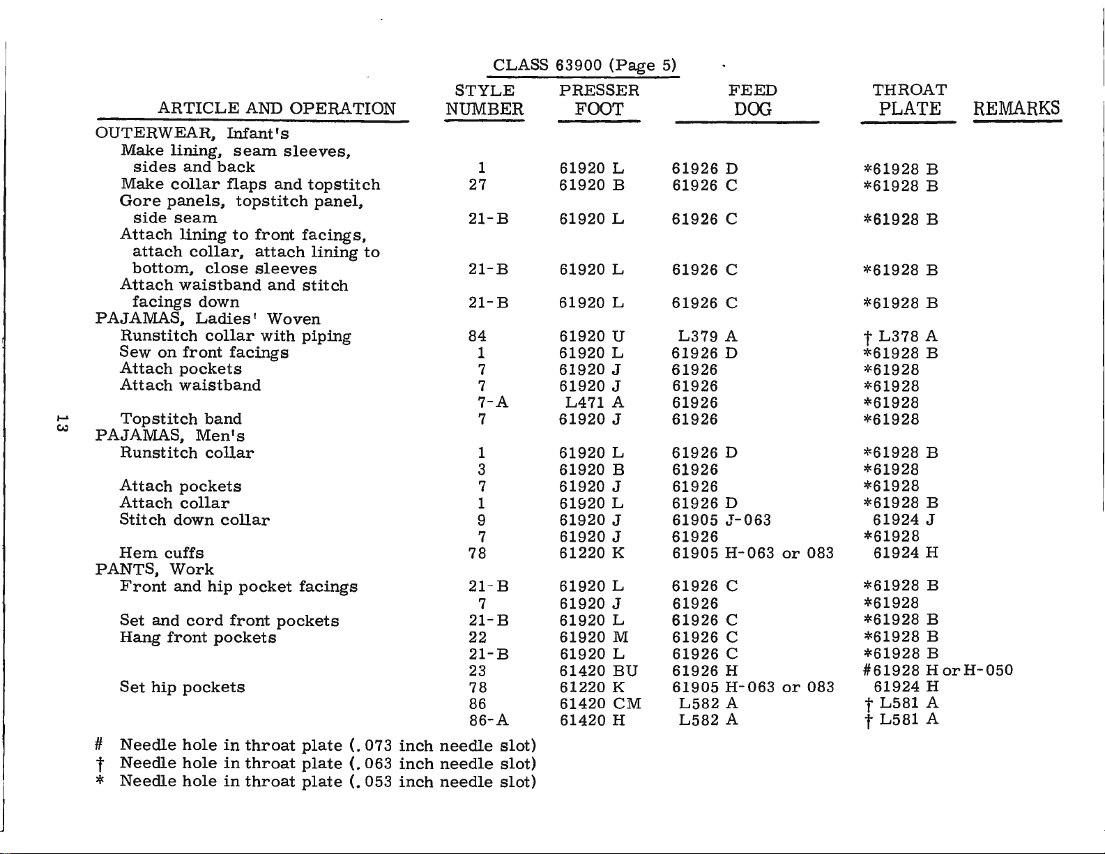
CLASS
63900
(Page
5)
OUTERWEAR,
Make
Make
Gore
Attach
Attach
PAJAMAS,
Runstitch
Sew
Attach
Attach
I-'
c.:,
Topstitch
PAJAMAS,
Runstitch
Attach
Attach
Stitch
Hem
PANTS,
Front
Set
Hang
Set
ARTICLE
lining,
sides
collar
panels,
side
seam
lining
attach
bottom,
waistband
facings
on
pockets
waistband
pockets
down
cuffs
Work
and
and
front
hip
Infant's
and
back
flaps
collar,
close
down
Ladies'
collar
front
band
Men's
collar
collar
collar
hip
cord
pockets
pockets
AND
seam
and
topstitch
to
front
attach
sleeves
and
Woven
with
facings
pocket
front
pockets
OPERATION
sleeves,
topstitch
panel,
facings,
lining
stitch
piping
facings
to
STYLE
N
UMBER
1
27
21-B
21-B
21-B
84
1
7
7
7-A
7
1
3
7
1
9
7
78
21
- B
7
21-B
22
21-B
23
78
86
86-A
PRESSER
FOOT
61920
61920
61920
61920
61920
61920
61920
61920
61920
L471
61920
61920
61920
61920
61920
61920
61920
61220
61920
61920
61920
61920
61920
61420
61220
61420
61420
L
B
L
L
L
U
L
J
J
A
J
L
B
J
L
J
J
K
L
J
L
M
L
BU
K
CM
H
61926
61926
61926
61926
61926
L379
61926
61926
61926
61926
61926
61926
61926
61926
61926
61905
61926
61905
61926
61926
61926
61926
61926
61926
61905
L582
L582
FEED
DOO
D
C
C
C
C
A
D
D
D
J-063
H-063
C
C
C
C
H
H-063
A t
A t
or
or
083
083
*61928
*61928
*61928
*61928
*61928
t
*61928
*61928
*61928
*61928
*61928
*61928
*61928
*61928
*61928
*61928
*61928
*61928
*61928
*61928
*61928
#61928
THROAT
PLATE
B
B
B
B
B
L378
61924
61924
61924
L581
L581
A
B
B
B
J
H
B
B
B
B
HorH-050
H
A
A
REMARKS
#
t
*
Needle
Needle
Needle
hole
hole
hole
in
in
in
throat
throat
throat
plate
plate
plate
(.
(.
(.
073
063
053
inch
inch
inch
needle
needle
needle
slot)
slot)
slot)
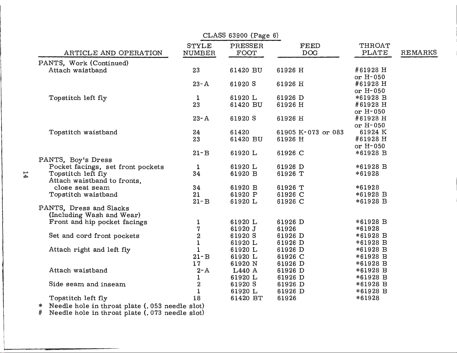
CLASS
63900
(Page
6)
....
..i:,.
PANTS.
Attach
Topstitch
Topstitch
PANTS,
Pocket
Topstitch
Attach
close
Topstitch
PANTS,
(Including
Front
Set
Attach
Attach
Side
Topstitch
Needle
*
#
Needle
ARTICLE
Work ( Continued)
waistband
Boy's
facings,
waistband
seat
Dress
and
and
cord
right
waistband
seam
hole
hole
AND
left
fly
waistband
Dress
set
left
fly
to
seam
waistband
and
Slacks
Wash
hip
and
left
pocket
front
and
inseam
fly
in
throat
in
throat
and
left
OPERATION
front
fronts,
Wear)
pockets
pockets
facings
fly
plate
plate
(.
(.
053
073
needle
needle
STYLE
NUMBER
23
23-A
1
23
23-A
24
23
21-B
1
34
34
21
21-B
1
7
2
1
1
21-B
17
2-A
1
2
1
18
slot)
slot)
PRESSER
FOOT
61420
61920
61920
61420
61920
61420
61420
61920
61920
61920
61920
61920
61920
61920
61920
61920
61920
61920
61920
61920
L440
61920
61920
61920
61420
BU
S
L
BU
S
BU
L
L
B
B
P
L
L
J
S
L
L
L
N
A
L
S
L
BT
61926
61926
61926
61926
61926
61905
61926
61926
61926
61926
61926
61926
61926
61926
61926
61926
61926
61926
61926
61926
61926
61926
61926
61926
61926
FEED
DOG
H
H
D
H
H
K-073
H
C
D
T
T
C
C
D
D
D
D
C
D
D
D
D
D
or
083
THROAT
PLATE
#61928
or
H-050
#61928
or
H-050
*61928
#61928
or
H-050
#61928
or
H-050
61924
#61928
or
H-050
*61928
*61928
*61928
*61928
*61928
*61928
*61928
*61928
*61928
*61928
*61928
*61928
*61928
*61928
*61928
*61928
*61928
*61928
REMARKS
H
H
B
H
H
K
H
B
B
B
B
B
B
B
B
B
B
B
B
B
B
CLASS
63900
(Page
7)
....
c.n
ROBES.
Bind
panels
Hem
Sew
SHIRTS,
Runstitch
Topstitch
Attach
Join
Topstitch
Attach
Stitch
Runstitch
Topstitch
Hem
Hem
Needle
*
ARTICLE
Ladies'
collar
bottom
collar
Dress
shoulders
down
bottom
button
and
collar
collar
collar
collar
collar
cuffs
cuffs
hole
and
down
collar
front
in
AND
cuffs,
bottoms
and
Sport
band
(one
band
(first
(second
throat
OPERATION
front
operation)
operation)
operation)
plate
(.
053
inch
STYLE
NUMBER
81
82
31
31-A
9
9-A
1
3
4
4-A
4-B
4-C
1
2-B
5
5-A
2-B
6
39
7
7-B
1
7
7-B
2-B
1
3
4
1
76
2-B
needle
hole)
PRESSER
FOOT
61920
L391
61420
61920
61920
L471
61920
61920
61927
61320
61420
61920
61920
61920
61420
L440
61920
61920
61920
61920
61920
61920
61920
61920
61920
61920
61920
61927
61920
L460
61920
T
A
AP
M
J
A
L
B
A
P
R
B
L
M
BT
A
M
F
D
J
P
L
J
P
M
L
B
A
L
A
M
61926
61926
61926
61926
61905
61905
61926
61926
61926
61926
61926
61926
61926
61926
61905
61905
61926
61905
61926
61926
61926
61926
61926
61926
61926
61926
61926
61926
61926
61926
61926
FEED
DOG
B
B
J-063
J-063
D
A
A
A
A
D
D
B-063
or
083
B-063
or
083
D
F-063
D
D
D
D
A
D
A
D
or
or
073
073
THROAT
PLATE
61928
61928
*61928
*61928
61924
61924
*61928
*61928
*61928
*61928
*61928
*61928
*61928
*61928
61924
61924
*61928
61924
*61928
*61928
*61928
*61928
*61928
*61928
*61928
*61928
*61928
*61928
*61928
*61928
*61928
M-053
M-053
J
J
B
1 / 4
3 /.16
A 1 /.16
A
1
/. 8 inch
A
/.
3 2
3
A
3 /.16
B 1
/. 4 inch
B
1 / 4
B
B
B
C
B
Attachment
B
B
B
A
B
A
B
REMARKS
inch
inch
1/8
inch
inch
inch
inch
margin
margin
margin
margin
margin
margin
margin
margin
inch
req.
hem
CLASS
63900
(Page
8)
....
O')
SHIRTS,
Attach
Quilt
Set
pockets
Hem
Attach
SHIRTS,
Attach
Runstitch
Attach
Set
pockets
SHIRTS,
Runstitch
Attach
Sew
Attach
Hem
SHORTS
Attach
Attach
Attach
Attach
finish
SHORTS,
Form
ARTICLE
Dress
facing
collar
top
sleeve
Knit
front
and
Work
collar
down
collar
work
AND
facings
pockets
and
elastic
Men's
right
of
pockets
Sport
cuffs
stitch
and
collar
shirts
SLACKS,
close
band
band
and
and
AND
and
to
facings
facings
top
and
band
to
to
Woven
OPERATION
Sport ( Continued)
left
front
(continuous)
and
collar
down
Heavy
stitch
cuffs
and
pockets
pockets
waistband
left
collar
Sport
cuffs
Ladies'
fly
collar
and
and
and
cuffs
cuffs
STYLE
NUMBER
2-B
1
7
7
85
8
8
9
9
11
10
12-A
10
12-A
13
14
15
19
77
27
28-A
27
26
23
7
7-B
PRESSER
FOOT
61920
61920
61920
61920
61220
61920
61920
61920
61920
61920
61920
61920
61920
61920
61920
61920
61920
L310
L427
61920
61920
61920
61920
61420
61920
61920
M
L
J
J
K
B
B
J
J
C
A
A
A
A
J
J
A
A
A
B
A
B
B
BU
J
P
61926
61926
61926
61926
L582
61905
61905
61905
61905
61905
61905
61905
61905
61905
61905
61905
61905
61926
61926
61926
61905
61926
61905
61926
61926
61926
FEED
DOG
D
D
A
J-063
J-063
J-063
J-063
C-073
C-073
K-073
C-073
K-073
E-073
G-073
B-063
or
083
C
E-073
C
C-073
H
or
or
or
or
083
083
083
073
THROAT
PLATE
*61928
*61928
*61928
*61928
t
L581
61924
61924
61924
61924
61924
61924
61924
61924
61924
61924
61924
61924
*61928
*61928
*61928
61924
*61928
61924
#61928
or
H-050
*61928
*61928
B
B
A
J
J
J
J
1 / 4
C
C 1 / 4
K 1 / 4
C
K
E
G
B
B
E
B
C
H
REMARKS
inch
margin
inch
margin
inch
margin
*
1
Needle
Needle
Needle
hole
hole
hole
in
in
in
throat
throat
throat
plate
plate
plate
(.
(.
(.
053
063
073
needle
needle
needle
slot)
slot)
slot)
CLASS
63900
(Page
9)
SHORTS.
SHIRTS.
SLIPS.
SNOW
....
-:i
SWEATERS,
SWIM
SWIM
ARTICLE
Men's
French
Attach
Make
attach
band
Material
Topstitch
Make
seam,
Attach
anklets
Edgestitch
Attach
Make
Close
Sewing
Seam
Make
Join
Close
Close
band
waistband
Ladies'
bows.
Cotton
SUITS,
liner,
hood,
button
SUITS,
shoulder
back
SUITS,
bra
bra
shoulder
lining
bra
top
AND
Woven
hem
Cotton
sew
waistband
and
right
side
Ladies'
lining
darts
of
and
Children's
attach
and
hood
fronts
and
Ladies'
straps
seam
Ladies'
lining
straps
and
trunks
swim
OPERATION
(Continued)
and
lining
and
stitch
Woven
rear
Lined
sleeves,
center
lining,
Cardigan
buttonhole
Woven
Knit
to
fronts
suit
Wool
to
back.
down
Synthetic
side
panels
seat
seam
cuffs
facings
and
STYLE
NUMBER
18
2-B
3
1
7-B
1
12
12-A
33
16
18
18
- A
30
30-A
28
28-A
29
1
18
1
1
1
PRESSER
FOOT
61420
61920
61920
61920
61920
61920
61920
61920
61920
61920
61420
61920
61920
61920
61920
61920
61420
61920
61420
61920
61920
61920
BT
M
B
L
P
L
S
A
M
R
BT
C
L
A
B
A
BT
L
BT
L
L
L
61926
61926
61926
61926
61926
61926
61905
61905
61926
61905
61926
61926
61926
61926
61905
61905
61905
61926
61926
61926
61926
61926
FEED
DOG
D
D
D
K-073
K-073
E
J-063
E-073
E-073
J-063
D *
D
D
D
or
or
083
083
THROAT
PLATE
*61928
*61928
*61928
*61928
*61928
*61928
61924
61924
*61928
61924
*61928
*61928
*61928
*61928
61924
61924
61924
61928
*61928
*61928
*61928
*61928
REMARKS
B
B
B
K
K
C
J
E
E
J
B
B
B
B
*
Needle
hole
in
throat
plate
(.
053
needle
slot)

INSTALLING
CAUTION!
hand
and
the
on
handwheel.
Before
carefully
packing
leaving
box,
PREPARATION
A
bag
of
attaching
screw,
miscellaneous
Insert
the
upper
STANDARD
Included
one
bobbin
clamp
and
screw,
essential
hinge
frame
ACCESSORIES
also
winder
spring,
four
when
When
Using
factory,
packed.
the
following
OF
MACHINE
assembly
one
extra
attachments
studs
eyelet
with
each
assembly,
one
knee
isolator
setting
unpacking,
both
each
After
the
steps
parts,
bobbin,
to
the
in
holes
(A,
Fig. 2 or
machine
the
lifter
pads
up
the
assembly
and
machine.
DO
hands
on
UNION
machine
should
FOR
INSTALLATION
consisting
two
bed
provided
2A).
is
machine
clips,
NOT
bed
SPECIAL
and
hinge
plate,
for
box
of
and
and
lift
machine
casting,
accessories
be
followed:
of
one
frame
studs,
is
packed
them
STANDARD
mounting
its
one
in
rubber
machine
out
of
box
by
placing
lift
gently.
machine
and
with
rear
is
have
thread
two
each
of
cloth
sewed
been
eyelet,
screws
machine.
plate.
off,
removed
ACCESSORIES--containing
frame,
pad,
rest
one
bed
oil
drain
positioning
pin.
These
inspected
one
eyelet
for
holding
Assemble
jar
and
spring
parts
one
from
its
are
TABLE
Lockstitch
the
bed
TABLE
BOARD
TOPS
plate
machines
is
FLUSH
are
with
installed
the
top
of
in
the
table
tops,
machine
prepared
mounting
with
frame.
63474A
cut-
out,
63476
so
B
that
'--
660-168
21393S
18
Fig.
1

E,"
B
MACHINE
On a suitable
cut-out
through
over
the
nuts
1/16
ing
the
shown.
must
with
left
right
retaining
lightly.
Place
inch
plate
board
Tip
All
not
MOUNTING
the
hinge
hinge
hinge
sewing
clearance
smartly
and
machine
end
bind.
pad;
plate
tighten
play
FRAME
tableboard,
lugs
pad
and
tighten
insert
(21393 R)
head
upward
back
in
between
locking
against
of
the
INSTALLATION
place
to
the
round
to
the
frame
the
with a hammer
nuts
cross
machine
rear
securely.
head
outside
mounting,
cloth
rest
plate
securely.
pin,
shaft
(Fig.
should
mounting
1).
Assemble
wood
front
19
screw
of
edge
to
insure a good
and
assemble
be
Insert
pan
and
and
taken
frame
the
bed
positioning
and
tighten
section,
after
the
frame
the
up
(21393
countersunk
as
being
grip
knee
by
the
N)
securely.
shown;
sure
sides,
on
press
cone
Fig.
in
the
wood
spring
and
there
rap
the
underside
assembly
bearings,
2
machine
screw
(63474
Assemble
snug
is
about
the
retain-
A)
up
of
as
but

WRAP
THREAD
ROT
ARY
COMPLETE
THEN
THREAD
P
OST
EYELET {K).
DISK{J)
TURNS
AROUND
TWO
...
TENSION
-
C
MACHINE
Before
lifter
the
within
raises
BOBBIN
located
when
allow
The
against
described
BELTS
rod
maximum
the
approximately
The
directly
in
operation.
the
pulley
the
These
MOUNTING
the
machine
should
head.
WINDER
bobbin
mechanism
of
belt
under
machines
be
lift
of
This
winder
in
the
to
"Winding
FRAME
adjusted.
the
presser
may
5/16
should
front
The
base
to
be
winder,
wind
the
are
INSTALLING ( Continued)
INSTALLATION ( Continued)
is
put
into
production,
The
left
stop
bar
and
its
parts
be
done
inch.
of
the
of
moved
when
bobbin.
the
equipped
by
be
secured
sewing
the
winder
closer
in
operation,
Regulation
Bobbin",
to
use
setting
to
machine
has
to
or
under
either
20
the
bell
screw
the
the
two
farther
and
OPERATOR'S
(22597
do
not
stop
table
belt
elongated
should
operation
#1
"Vee"
interfere
screw
top
and
away
exert
crank
will
or
(21665
F)
should
with
so
that
the
so
that
its
bear
attaching
from
only
of
INSTRUCTIONS.
round
the
the
against
belt
enough
bobbin
belts.
Fig.
J)
of
be
set
moving
presser
pulley
holes,
as
2A
the
knee
so
that
parts
bar
will
the
belt
which
needed.
pressure
winder
be
is

THREADING
Thread
Thread
these
thread
machines
handling,
machine
machine
Threading
is
threaded
from
CAUTION!
the
reservoir
Lubricate
run
slowly
operation
for
can
must
machine
then
RECOMMENDED
Use a stainless
125
seconds
Special
and
check
marked
It
an
extended
oil
the
end
cover
is
bearings
at
specification
oil
level
"FULL".
recommended
period,
as
no
are
equipped
the
at
check
left
Oil
be
several
be
OIL
water-white
100°
at
gauge ( C).
Oil
of
the
further
Styles
Styles
thread
63900 A and B as
63900
should
spring
to
right.
has
been
filled
thoroughly,
minutes
expected
Fahrenheit
No.
175.
should
that a new
be
lubricated
needle
hand
C, D and
with a rotary
be
wound
has
been
LUBRICATION
drained
before
to
without
from
starting
in
accordance
distribute
damage.
straight
in
the
main
Fill
main
Oil
is
at
maximum
be
added
when
machine,
as
follows:
bar
link,
oiling
take-
will
indicated
AL
needle
TWICE
enlarged
the
to
the
mineral
reservoir.
reservoir
needle
or
up
and
be
required.
as
indicated
tension
around
in
both
main
reservoir
operate.
with
oil
to
oil
of a Saybolt
at
level
is
in
one
that
Remove
its
in
Fig.
in
assembly,
the
Figures
instructions
the
various
This
plug
when
yellow
the
lever
has
is
screw
needle
band
been
head
and
2.
Fig.
rotary
before
to
for
which
parts.
2A,
noting
insure
tension
clarity.
shipment,
follow,
Full
viscosity
equivalent
(B,
Fig. 2 or
is
in
yellow
marked 11LOW"
out
of
service
cover
needle
and
bar.
that
proper
disc
Needle
and
speed
of
90
to
Union
2A)
band
directly
Replace
.
so
to
.
for
Oil
OIL
GAUGE
The
Should
Lubrication
through
the
shaft
is
secured
may
be
oil
gauge
an
adjustment
the
feed
at
the
to
drained
Fig.
of
driving
sprocket
the
bottom
from
is
set
become
3
the
mechanism
main
at
the
shaft
end
cover
reservoir
factory
necessary,
1.
2.
3.
4.
5.
below
(D,
Fig.
by
means
(B)
by
by
to
show
the
Place
the
bench.
Remove
below
the
machine).
Oil
should
level
is
bottom
Loosen
and
turn
r.auge
needle
'FULL"
Tighten
the
cloth
3),
which
of
an
means
removing
the
proper
following
machine
the
reservoir
handwheel
be
added
approximately
edge
the
the
of
lock
screw
the
rests
on
gauge ( C,
lock nut
plate
oil
distributing
of
two
is
tubular.
screws
is
plug
screw
oil
level
steps
should
upright
plug
and
near
or
removed
hole.
nut
on
the
left
on
the
Fig. 2 or
and
replace
automatically
Oil
plate
(C).
(D,
in
the
be
on a level
screw
the
1/8
inch
calibrating
or
right
yellow
plug
is
introduced
(A,
Fig. 2 or
2A) .
reservoir.
followed:
table
(located
bottom
so
that
of
the
below
screw,
so
that
band
marked
2A).
screw.
accomplished
into
Fig.
3)
which
or
the
oil
the
the
Should
the
adjustment
done
by
through
slightly
it
become
of
removing
the
hole.
below
the
the
the
The
center
necessary
oil
distributing
large
low
point
of
plug
the
to
remove
screw
of
shaft
plate
the
(D)
the
(A) _
be
at
the
oil
distributing
and
just
reservoir
checked
right
•end
touching
21
cover,
very
of
the
plate
it.
it
is
imperative
carefully.
reservoir
must
be
This
and
even
that
can
looking
with
be
or
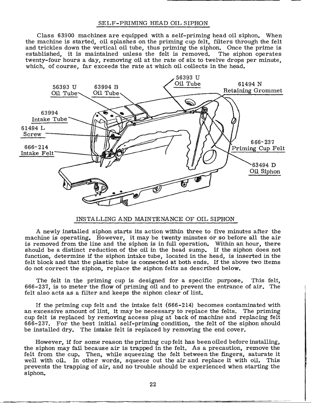
SELF-PRIMING
HEAD
OIL
SIPHON
Class
the
machine
and
trickles
established,
twenty-four
which,
63994
Intake
61494
Screw
666-214
Intake
L
Felt-------\~
63900
is
down
it
hours a day,
of
course,
Tube
machines
started,
the
is
maintained
far
are
oil
splashes
vertical
removing
exceeds
A
~fQ'!-
equipped
on
oil
tube,
unless
oil
the
rate
with a self-priming
the
thus
the
at
at
priming
priming
felt
the
rate
which
cup
is
removed.
of
six
oil
collects
the
head
felt,
siphon.
to
twelve
in
filters
Once
The
drops
the
oil
siphon.
through
the
siphon
head.
61494
Priming
the
prime
operates
per
minute,
N
666-237
Cup
63494
Oil
Siphon
When
felt
is
Felt
D
A
newly
machine
is
removed
should
function,
felt
block
do
not
correct
The
666-237,
felt
also
If
the
an
excessive
cup
felt
666-237.
be
installed
However,
the
siphon
felt
from
well
prevents
siphon.
with
INSTALLING
installed
is
operating.
from
be a distinct
determine
and
felt
is
to
acts
priming
is
replaced
For
dry.
may
the
oil.
the
the
that
the
in
the
meter
as a filter
amount
the
if
for
fail
cup.
In
trapping
siphon
line
reduction
if
the
the
plastic
siphon,
priming
the
cup
felt
of
by
best
The
intake
some
because
Then,
other
of
AND
starts
However,
and
the
of
siphon
tube
replace
cup
flow
of
and
keeps
and
the
lint,
removing
initial
reason
air
while
words,
air,
it
may
self-priming
felt
and
MAINTENANCE
its
action
it
may
be
siphon
the
intake
is
the
is
priming
the
intake
be
access
is
the
priming
is
trapped
squeezing
squeeze
no
trouble
is
oil
in
tube,
connected
siphon
designed
oil
siphon
felt
necessary
plug
replaced
out
within
twenty
in
full
the
head
located
at
both
felts
for a specific
and
to
clear
(666-214)
to
at
back
condition,
by
removing
cup
felt
in
the
felt.
the
felt
the
air
should
OF
OIL
three
minutes
operation.
sump.
as
prevent
of
replace
has
between
and
be
experienced
to
in
the
head,
ends.
described
the
lint.
becomes
of
machine
the
felt
the
been
As a precaution,
replace
SIPHON
five
minutes
or
so
before
Within
If
the
is
If
the
below.
purpose.
entrance
contaminated
the
felts.
and
of
the
end
cover.
oiled
the
before
fingers,
it
when
an
hour,
siphon
inserted
above
of
The
replacing
siphon
remove
with
starting
after
all
does
two
This
air.
installing,
saturate
oil.
the
the
air
there
not
in
the
items
felt,
The
with
priming
felt
should
the
This
the
it
22

THREAD
INSTRUCTIONS
FOR
OPERA
TORS
While
of
the
hook
the
direction
of
each
unwind,
WINDING
from
down
post.
up
to
a
few
wardly
contact
position.
will
automatic
pulley.
varied
hand.
Fig.
Thread
the
between
Press
the
turns
on
be
rotated
The
by
the
direction
rotation
of
twist,
Turn
it
is a left
4
THE
supply
stop,
with
When
regulating
BOBBIN
the
bobbin
down
the
tension
an
empty
wind
in a clockwise
hand
throw-out
lever
machine
the
and
extent
of
favors
grasp a short
the
thread
twist,
REMOVING
direction
the
latch
hook.
the
be
winder
through
discs,
bobbin
the
end
(D)
belt,
machine
filled
to
until
member,
which
the
screw
the
twist
the
use
away
if
not,
it
To
remove
until
left
hand,
(A,
Fig.
Opening
latch
removed.
of
direction,
until
the
by
the
and
on
the
thread
pulley
and
is
operated,
the
which
bobbin
{C).
is
in
the
of a left
length
from
is a right
THE
the
the
reach
4),
the
latch
closed,
leading
eyelet
under
winder
around
and
press
is
is
locked
thread
disengages
is
filled
bobbin
twist
of
thread
you
twist.
BOBBIN
bobbin
needle
under
and
pull
retains
the
the
thread
{A,
Fig.
the
tension
shaft
the
bobbin
down-
moved
in
the
bobbin
engages
can
thread
thread
with
your
CASE
case,
reaches
the
the
bobbin
5),
(B)
into
that
the
the
be
is
immaterial,
in
the
between
right
turn
its
table,
bobbin
the
bobbin
is
released
needle.
thumb
hand.
handwheel
highest
case
open
in
position.
out
the
To
and
If
the
and
the
direction
determine
forefinger
the
in
operating
bobbin
of
the
case.
can
strands
Using
case
sewing
When
readily
The
base,
screw
unevenly
operator
replace
can
and
(E)
The
be
tension
can
be
so
that
may
purpose
of a full
it
with
rewound
Fig.
post
be
of
the
while
bracket
shifted
any
readily
the
bobbin
full
the
6
is
from
tendency
bobbin
one,
left
corrected.
at
all
and
machine
mounted
to
of
winder
times.
begin
is
THREADING
forefinger
(A,
and
thread
on
right
the
bobbin
is
to
sewing.
The
bobbin
F
ig.
The
bobbin
forefinger
23
the
by
loosening
to
to
assure
When
wind
coming
the
THE
and
6).
winder
wind
an
the
bobbin
empty
BOBBIN
case
should
second
itself
of
the
off
one
finger
should
right
the
in
the
machine
immediately.
CASE
beheld
of
be
held
hand
bottom
F
ig.
5
between
the
between
(B,
Fig.
of
the
is
used
Bobbins
the
LEFT
the
6)
bobbin.
up,
thumb,
hand
thumb
with

INSTRUCTIONS
FOR
OPERA
TORS
(Continued)
THREADING
Place
and
forefinger
bobbin
(C)
on
is
pulled
as
it
facing
The
(A,
Fig.
inserted
the
accumulated
case
case.
\
Fig.
will
the
the
when
go
handwheel.
cross
8).
as
THE
(A,
Note
7
with
far
BOBBIN
bobbin
of
the
Fig.
the
looking
C
the
hole
is
to
up
as
lint
CASE
in
the
bobbin
right
counterclockwise.
REPLACING
and
latch
the
part
and
INSERTING
spot
in
show
it
from
hand,
7)
under
direction
at
the
Have
one
should
table
way
bobbin
Insert
(sometimes
Tighten
the
needle
the
will
go,
needle
the
of
bobbin
the
half
and
into
the
set
operator
and
hole
(Continued)
case.
draw
case
the
tension
the
rotation
case
THE
needle
be
through
the
THE
screw
bar,
to
BOBBIN
bar
inches
opened
sewing
snapped
NEEDLE
needle
called
about
when
provide a means
so
the
In
one
bobbin
spring
of
from
of
the
into
securely.
needle
the
at
its
thread
with
the
opening
hook.
into
the
scarf)
1/ 4 inch
the
continuous
thread
(B)
the
CASE
highest
position.
needle
toward
needle
will
and
bobbin
back.
to
left
in
The
from
seat
through
hang
hand,
the
latch
for
motion,
into
self
as
the
The
position,
free.
and
table,
should
bar
as
the
right,
the
has
been
cleaning
properly.
the
diagonal
threading
end
bobbin
allow
The
by
it
should
then
far
end
with
the
of
the
should
about
bobbin
reaching
be
be
released
A
thumb
slot
in
eyelet
thread
rotate
two
case
under
placed
THREADING
Threading
thread
from
PREPARATION
the
highest
it
foot.
the
in
passes.
left
With
handwheel
through
bobbin
the
your
position.
Fig.
eyelet
to
the
case
right.
9
THE
diagram
Please
FOR
left
in
needle
B
and
for
this
NEEDLE
(Fig.
note
SEWING
hand,
operating
Pull
hold
up
hole
TENSIONS
A
thread
sewed.
tensions
BOBBIN
The
screw
tension
bobbin
adjustment
2)
shows
that
the
end
direction
the
needle
in
the
throat
perfect
are
locked
A
stitch
on
both
THREAD
tension
(A,
Fig.
on
the
suspended
check.
the
needle
of
until
thread
stitch
threads.
on
9)
spring
by
the
places
thread
the
needle
the
needle
and
plate.
is
together
of
TENSION
the
which
the
one
this
bobbin
is
correct
bobbin
Draw
where
passes
thread,
moves
the
bobbin
both
in
which
in
the
kind
regulates
is
case
when
thread.
the
leaving
thread
threads
the
needle
center
secured
is
applied
tension
it
The
needle
through
down
of
is
just
thread
the
it
slack,
and
up
will
come
under
thread
the
material
by
regulating
by
means
spring
sufficient
should
Fig.
needle
and
again
the
and
(B).
8
eye
turn
to
its
up
with
presser
bobbin
being
the
of a set
The
to
hold
not
be
24

INSTRUCTIONS
FOR
OPERATORS
(Continued)
BOBBIN
Remove
clockwise
When
any
changes
NEEDLE
The
(F,
counterclockwise
its
raised
scrap
TO
CHANGE
Press
in
operating
feed
handwheel
length
length.
THREAD
direction
the
THREAD
needle
Fig.
2).
position,
material.
plunger
eccentric.
in
and
the
bobbin
as
Turning
THE
direction
in
TENSION
bobbin
to
thread
varying
TENSION
thread
decreases
but
STITCH
(G,
Continuing
operating
opposite
case
apply
tension
the
tension
the
nut
is
generally
LENGTH
Fig.
2)
until
direction
direction
(Continued)
from
more
needle
in a clockwise
it.
in
stitch
to
is
thread
is
This
firmly.
regulating
hold
to
to
its
tension
correct,
varied
should
done
the
increase
decrease
holder
or
tension
by
direction
not
while
While
plunger
and
turn
counterclockwise
it
rarely
will
turning
be
done
the
machine
holding
finger
in,
turn
the
stitch
the
stitch
set
becomes
usually
the
increases
when
plunger
is
felt
-
screw
attain a good
tension
the
is
sewing
to
drop
in
to
release
necessary
regulating
the
tension,
presser
in,
turn
into
spring
on a piece
handwheel
the
in
tension.
to
make
stitch.
while
foot
is
slot
a
nut
in
of
of
Stitch
indicator
belt
guard
NOTE:
together.
connecting
they
are
synchronized.
PRESSURE
The
presser
to
make
pressure
regulator
the
regulator
lengths
dial
(H,
The
If
not
stud
ON
the
on
(G,
counterclockwise
and
Fig.
needle
loosen
(B)
MA
spring
work
the
Fig.
are
are
forward
TE
presser
16)
viewed
2).
feed
RIAL
should
feed
indicated
through
and
nut
(A,
or
backward
·Tighten
exert
uniformly.
foot,
in
clockwise
by
graduations
the
drop
Fig.
nut
(A)
only
turn
direction.
decreases
the
window
feed
10)
and
to a point
securely.
enough
To
increase
presser
the
should
reposition
pressure
Turning
pressure.
on
the
in
the
move
where
the
spring
Fig.
10
25

INSTRUCTIONS
FOR
MECHANICS
SETTING
The
is
faced
to
the
throat
Fig.
bar
is
used.
THE
lower
to
height
11
NEEDLE
end
at
plate
BAR
of
the
needle
the
factory.
seat
is 2 17/64
The
needle
two
183,
bar
upper
which
The
Type
180,
When
line
(B,
Fig.
used,
frame
until
screw
needle
should
(A).
To
change
the
(C)
bar
The
needle
bar
needles,
or D using
same
manner,
TO
HEIGHT
bar
frame,
The
inches.
four
lines
to
height,
lines
two
are
is
recommended
lower
which
the
needle
11)
(of
be
EVEN
the
bar
is
at
and
move
line
at
illustration
on
Styles
Type
183.
short
length
except
the
distance
engraved
and
are
used
with
lines
is
recommended
bar
is
the
pair
with
position
its
lowest
the
bar
its
lowest
(Fig.
63900
The
setting
needles,
that
one
from
on
ref
the
for
are
used
at
its
selected)
the
of
the
position.
to
the
position,
11)
A, C
of
the
lower
to
which
the
the
needle
erred
extra
Styles
for
lowest
lower
needle
proper
shows
or
the
Type
bottom
to
short
63900
with
the
Styles
position,
dependent
edge
Then,
timing
tighten
the
AL
using
needle
180,
pair
the
needle
of
frame
bar
are
as
TIMING
length
A, C
short
63900 B
of
the
bar,
turn
loosen
line.
screw
proper
extra
bar
on
is
accomplished
of
timing
bar
used
needle
and
length
the
upper
upon
lower
the
setting
short
Styles
marks
is
timed,
(A,
Fig.
in
setting
LINES.
Type
AL.
needle
and
D.
timing
the
needle
needle
handwheel
the
clamp
Keeping
securely.
of
length
63900
in
on
11)
The
bar
the
the
B
the
the
TIMING
pin
two
finger
in
the
in
such a position
needle.
the
to
turn
the
used
edge
THE
Tip
the
in
the
screws,
(A,
hook,
Turn
needle
the
lower
in
setting
of
the
timing
Turn
hook
to
spacing
With
Then,
hook
should
the
is
even
needle
of.
the
hook
tighten
with
be
Adjust
until
case
inch
case
the
finger
holder
clearance
recess
HOOK
machine
table
and
Fig.
and
top.
swing
12).
hold
as
handwheel
bar
is
at
handwheel
mark
the
needle
the
hook
with
the
as
possible
003
to.
in
this
the
two
the
needle.
about
the
1 /
64
bobbin
recess
recess
between
(Fig.
12).
back
so
Insert a new
out
the
Loosen
the
to
its
until
(of
needle
bar
frame
on
the
center
the
hook
prevent
in
operating
lowest
the
the
bar
shaft
of
without
005
inch
between
position,
remaining
At
the
inch
below
case
and
is
at
tighten
the
holder
the
outside
that
it
rests
needle.
bobbin
case
three
and
bobbin
interference
position,
needle
pair
is
is
selected)
even
(A).
until
the
needle
deflecting
the
tighten
screws
hook
the
timing
bottom
positioning
top.
Place
the
finger
edge
on
Loosen
positioning
set
screws
case
direction
and
ascending
with
the
the
point
and
needle
the
set
securely,
position
the
attaching
of
the
rest
the
(B)
holder
with
the
until
continue
and
(Fig.
11)
lower
of
the
as
close
it.
A
and
the
screw
of
finger
the
opposite
hook
by
projection
projection
point
and
the
top
point.
turning
on
screws
and
Fig.
12
of
the
hook
is
the
hook
recheck
of
the
the
the
finger
point
the
eye
bobbin
into
securely,allowing
the
inside
edge
satisfactory.
securely.
timing
of
case
the
the
of
the
needle
holder
bobbin
1/32
of
bobbin
26

INSTRUCTIONS
FOR
MECHANICS
{Continued)
In
{B,
Fig.
The
in
contact
toward
is
at
bottom
time,
of
guarding
related
1.
2.
3.
there
For
size . 048
Before
See
Check
Rotate
Check
cited
the
hook,
13)
is
purpose
with
the
hook
of
should
additional
and
surface
metal
settings
that
the
for
handwheel
for
excessive
above
NEEDLE
at
found a needle
of
this
the
needle
point.
its
vertical
be
needle
larger
may
removal
should
needle
proper
as a desirable
GUARD
the
right
guarding
The
little
clearance,
needles,
be
necessary.
from
be
checked
bar
hook
in
operating
needle
side
guarding
{D)
at
needle
travel,
or
no
removal
the
is
timing.
deflection
condition.
INSTRUCTIONS
of
the
needle
surface
surface
loop-taking
guard
deflection
guarding
as
set
is
to
will
if
the
hook
especially
of
some
surface,
follows:
to
correct
direction
beyond
prevent
time,
deflect
of
by
FOR
{A,
is
properly
needle
with
use
needle
height
hand
what
NO.
hole
Fig.
the
should
the
needle
by
all
.
.
is
in
13).
hook
the
the
29474
the
bobbin
point
needle
slightly,
timed.
needle
S
{ C)
from
be
(At
guard.)
Fig.
case
when
holder
coming
deflected
needle
loop-taking
13
4.
If
needle
(1)
Remove
Remove
(2)
using a 1/8
bench
is
the
proper
CAUTION!
needle
hook
REMOVED
pulling
slightly.
HOOK
damage
guarding
The
bobbin
base.
When
Bobbin
on
LUBRICATION
CAUTION!
may
deflection
and
removed.
bobbin
needle
Damage
surface.
case
altering
or
disturbed
case
holder
bobbin
Do
result.
bobbin
excess
inch
rubbing
When
case
holder
needle
case
not
is
excessive,
case
guarding
from
only
stem
run
metal
strip
the
metal
holder
to
hook
guarding
may
the
holder
should
its
as
from
from
of
guarding
machine
needle
fine
is
should
is
obtained.
point
be
timed
be
removed
the
handwheel
being
follow
hook.
guarding
emery
may
thoroughly
surface,
cloth
surface
removed
be
re-inserted
resttlt
position.
without
steps 1 and 2 below.
{#320),
back
if
it
is
by
removing
is
the
surface.
and
from
too
much
cleaned
suggested
rocked
bobbin
with
forth
frequently
This
one
until
needle
metal
before
gib
screws
backwards
case
may
end
secured
sufficient
guarding
and
is
removed
re-
assembly
the
hook
and
and
in
the
be
tested
gib
hook
done
surface
NOT
forwards
as
to
metal
until
from
into
BE
and
hook
by
the
by
,
With
piece
about
should
of
white
five
be
the
bobbin
paper
seconds,
observed.
case
directly
remove
in
the
the
hook,
under
paper
run
the
the
hook
and a definite
and
27
machine
continue
and
for a full
running
distinct
pattern
minute.
the
machine.
of
oil
Place
After
spots
a

INSTRUCTIONS
FOR
MECHANICS
(Continued)
HOOK
required,
ing
front
cloth
of
change
machine
minute
desired
FEED
feed
position
directly
and
or
dog
LUBRICATION
Should
turn
shaft
the
regulating
counterclockwise
holder
(E,
of
the
plate
change
in
before
oil
DOG
In
regulating
dog,
and
against
The
feed
surface,
should
it
rests
more
the
oil
Fig.
machine
required.
the
hook
be
checking
flow.
HEIGHT
should
the
presser
it.
dog
holder
screw
against
(Continued)
or
less
control
2),
located
just
in
the
oil
run
the
height
be
at
foot
(B)
to
lower
oil
adjust-
on
below
direction
After
flow,
about
for
of
its
highest
resting
attaching
should
it.
the
head
be
the
the
a
the
one
the
the
screw
be
turned
Make
of
sure
the
regulating
Feed
should
plate
16
depth
The
be
down
by
screws
(A,
either
that
A
or
feed
tilted
Fig.
dogs
at
as
1 o o s e n
14)
clockwise,
the
screw.
suggested
having
show
highest
less
of a full
teeth
dog
up
required
(A
and
Fig.
should
bottom
initial
about
point
tooth
can
or
in
g
C).
22
3 /
per
14
be
to
raise
of
the
setting
or
more
64
inch
of
travel.
inch
above
loosened
the
shank
is
teeth
above
Those
should
the
throat
slightly,
feed
of
the
as
follows:
per
the
throat
having
show
plate
dog,
feed
inch
the
.
Loosen
dog,
PRESSER
set
(B).
against
and
crank
the
accomplished.
screw
front
The
so
This
relocating
proper
that
the
(C).
in
to
BAR
presser
it
is
place.
By
Fig.
back
is
rest
setting
or
CONNECTION
bar
about
accomplished
pin,
the
stop
turning
Tighten
15
sideways
connection
1/16
of
inch
by
loosening
screw
the
stop
the
the
lock
in
the
(For
(A,
below
tipping
the
(B)
screw
presser
nut
on
throat
Styles
Fig.
the
the
lock
the
to
bar
(A)
dog
screws
space
plate.
63900
16)
presser
machine
nut
(A,
lifter
the
right
connection
to
lock
28
holding
(D)
the
A,
B)
should
bar
Fig.
lever
or
the
feed
to
feed
be
guide
back
15),
bell
left,
is
stop
Fig.
'
16

INSTRUCTIONS
FOR
MECHANICS
(Continued)
PRESSER
to
the
presser
BAR
Fig.
CONNECTION
16A
foot
by
turning
(For
Styles
should
abovethelowerpresserbarbushing(B,
This
against
Fig.
lifter
screw
the
Tighten
in
place.
PRESSER
Fig.
against
lowest
there
of
the
a
thin
from
(C).
on
the
dimension,
the
retighten
the
presser
63900
The
presser
be
set
is
accomplished
the
rest
15)
and
lever
to
the
presser
the
BAR
When
16),
is
To
the
Tap
needle
locating
the
the
throat
position.
a 4 5 / 8
needle
(.
085
obtain
presser
on
presser
throat
center
screw
spring
C,
D,
bar
so
that
pin,
relocating
bell
right
bar
lock
GUIDE
presser
The
inch
thread
inch
this
plate.
enters
(C)
regulator
crank
or
connection
nut
plate
thick)
setting,
spring
Set
the
in
AL)
it
bytipping
(A)
the
guide
space
take-up
foot
the
guide.
connection
is
approximately
loosening
the
stop
(C).
By
left,
to
(For
presser
foot
with
throat
(F)
to
the
foot
middle
(G)
the
lock
Styles
must
the
is
between
wire
remove
and
insure
guide
by
Now,
clockwise.
(A,
Fig.
the
machine
the
lock
screw
turning
proper
is
accomplished.
the
stop
63900
bar
rest
feed
set
properly
the
and
plate
loosen
to
turning
of
(Fig.
the
its
beini
the 4 5/ 8 inch
its
apply
Fi~.
1/
(B)
setting
guide
dog
underside
the
set
it
16A)
32
inch
16A).
back
nut
(A,
on
the
stop
screw
A,
B)
(B,
directly
in
when
top
16).
pressure
screw
down
so
that
slot
pressure
and
the
of
its
of
PRESSER
When
directly
is
set
properlywhen
er
bar
connection
To
16A)
throat
that
apply
4
PRESSER
presser
presser
5/8
and
plate.
the
pressure
Set
inches
The
BAR
locating
against
obtain
loosen
needle
the
needle
BAR
presser
feet.
bar
is
GUIDE
the
(A,
this
set
Set
the
enters
by
turning
above
bar
However,
adaptable.
(For
the
presser
throat
there
Fig.
setting,
screw
guide
the
thread
the
throat
No.
Styles
bar
plate
is a 1/16
16A).
remove
(E).
to
middle
the
pull-up
63457 J is
should
Tap
the
presser
plate
with
1/16
of
feet
63900
guide
inch
the
its
bracket
(Fig.
C, D,
(C,
the
feed
space
pressure
on
presser
inch
dimension,
slot
and
spring
(G)
16A).
designed
of a different
29
AL)
Fig.
regulator
16A)
dog
in
between
from
foot
to
retighten
so
that
primarily
manufacture
the
its
lowest
the
the
insure
center
screw
(F)
the
presser
position.
guide
presser
its
the
foot
(E)
clockwise.
underside
to
receive
(C)
spring
being
by
in
be
foot
must
The
and
the
(D,
down
turning
the
guide.
of
the
Union
required,
rest
guide
press-
Fig.
on
the
it
so
Now
wire
Special
the
is

INSTRUCTIONS
FOR
MECHANICS
(Continued)
PRESSER
To
adapt
follows:
1.
Remove
2.
Insert
3.
Loosen
the
4.
Attach
the
needle.
5.
Check
CAUTION!
the
presser
TENSION
BAR ( Continued)
the
machine
presser
presser
the
set
screw
ASSEMBLY
as a handle.
presser
the
presser
guide
foot
foot
screw
foot
When
height
to
receive
and
presser
screw
to
bar
presser
must
ADJUSTMENT
in
the
the
guide
in
the
presser
bar
for
feet
be
checked
and
other
presser
foot
presser
bar
align
correct
than
and
feet
screw
bar
guide
the
height
of
reset
of
from
so
and
needle
and
Union
where
other
presser
it
screws
rotate
hole
tighten
Special
manufacture,
bar.
in
from
presser
or
slot
set
manufacture
necessary.
bar
of
screw
proceed
right
180°
the
foot
securely
are
to
using
used,
as
left.
with
.
Test
should
snap
it
located
assembly,
loosen
socket ( C).
until
stop
post
again
the
should
tension
post
take-
should
TENSION
be
when
require
tension
the
(E)
(D)
touches
desired
be
can
(D)
Replace
up
wire.
be
and
check
enough
spring
adjusting,
under
and
Turn
check
and
in a clockwise
drawn
resting
RELEASE
spring
arm
remove
post
the
spring
has
no
the
tension
up
be
made
turning
tension
While
tension
is
depressed
loosen
set
tension
tension
upper
is
snugly,
by
in
assembly
the
on
the
tension
to
assure a good
set
and
obtained.
to
tension
screw
post
moves
on
direction
stop
yet
inserting
the
required
tension
throat
(E).
(A.
Fig.
and
released.
screw
the
right
assembly.
(B)
in
tension
(D)
counterclockwise
away
it.
not
with
plate.
from
Turn
until
Then,
When
post
correctly
forcefully.
a
screwdriver
direction.
the
check
assembly
17).
in
the
proceed
There
returning
Should
the
of
tension
Partially
the
upper
tension
the
spring
Further
spring
head
post
further
set,
into
is
being
in
the
the
tension
adjustment
the
slotted
about
3/8
replaced,
Fig.
same
post
of
inch
the
end
above
the
1 7
direction
set
screw
check
of
the
tension
the
presser
D
until
(B)
spring
thread
foot
The
seams
tension
are
required
tension
or
when
release
for
release
the
presser
cam
proper
should
(D,
Fig.
operation.
foot
16)
be
is
and
set
so
raised
the
in
30
that
for
and
it
will
back
out
tacking.
position
not
release
The
of
the
when
adjustment
tension
sewing
assembly
over
of
the

INSTRUCTIONS
FOR
MECHANICS
(Continued)
TENSION
insure a good
is
depressed
is
adjusted
with a postal
when
The
but
release
(D,
located
correct
the
tension
not
Fig.
RELEASE ( Continued)
Fig.
from
check
post
forcefully
pin
17).
just
below
height
18
returning
and
released.
about 1 to
scale
spring
set
tightened
should
The
the
as
follows:
(C,
is
screw
move
check
tension
The
correct
spring
so
that
it,
this
set
screw.
The
positioned
raising
The
average
presser
release
THREAD
Check
Check
snap
1/32
when
The
1 1 / 4
Fig.
to
should
(B,
freely
spring
19).
discs,
in
when
eyelet
when
position
tension
or
foot
cam
CONTROL
spring
spring
check
ounces
1/16
be
Fig.
in
eyelet
and
the
(A,
the
flange
is
by
loosening
lowering
release
lift
set screw
the
adjustment
tension.
spring
when
This
inch
is
from
drawn
17).
the
tension
(A,
should
out
position
tension
Fig.
18).
of
maintained.
release
the
cam
point
above
(B,
measured
measured
up
The
Fig.
be
securely.
(For
There
Fig.
tension
its
stop.
snugly
tension
set
the
post
18),
of
the
discs
Set
the
cam
set screw
is
Styles
of
19)
for
are
the
tension
Tighten
(D,
to
suit
between
throat
63900 A, B)
tension
should
tension
in
line
stop
screw
assembly
the
Fig.
16)
(E,
the
sewing
1/4
plate.
assembly
be
C
with
(B,
tension
should
Fig.
and
Tighten
enough
assembly
the
Fig.
rests
16)
(A,
against
assembly
now
and
conditions
5/16
inch
tension
Fig.
tension
is
check
18),
be
then
.
of
19).
to
With a thread
thread
should
(Fig.
discs
without
to
wire
18).
so
thread
in a straight
be
set
1/16
Be
sure
that
the
obstruction.
machine
Fig.
running
to
the
check
After
as
per
19A
from
line,
1/8
eyelet
spring
making
threading
inch
is
the
the
check
below
set
will
this
the
the
taut
Slight
necessary
should
stitch.
ounces
similar
Depress
The
compared
required
result,
tensionpost
spring
the
thread
close
pass
to
freely
setting,
diagram
Sew
action
check
when
changes
be
The
needle
thread,
check
the
eyelet
the
tension
over
proceed
(Fig.
slowly
of
the
spring
the
take-up
at
this
used
machines
check
spring
to
Class
setting
disc
to
the
line
it
2).
on a piece
check
to
the
is
in
needle
point,
to
maintain a uniform
thread
using a postal
spring
will
61900
for
tension
of
spring.
take-
at
the
thread
but a reasonable
are
tension
when
feel
adjustment,
the
Class
can
Fig.
material
The
up
wire
bottom
tension
sewn
checking
be
off
on
scale
heavy
63900,
reduced.
19
and
observe
thread
should
of
its
stroke.
may
tension
and
consistent
with 3 to
70-2 cord
(A,
Fig.
the
tension
to
you
but
this
and
from
be
be
or
20).
when
is
as
4
.
a
a
31

INSTRUCTIONS
FOR
MECHANICS
(Continued)
THREAD
Check
(A,
Fig.
should
ing
released.
from
postal
check
The
snugly
release
post.
NOTE:
needle
proper
disc.
being
check
proceed
be
snap
about
scale
spring
tension
but
thread
The
sure
spring
CONTROL
the
adjustment
19A).
enough
when
The
check
1/2
to 1 ounce
(C).
is
post
not
forcefully
pin
should
The
machine
thread
handling,
tension
that
to
to
thread
(For
Check
tension
spring
This
1/32
tension
the
set
move
post
eyelet
pass
machine
to
screw
Styles
spring
to
(B)
spring
when
is
1/16
tightened.
freely
is
equipped
assembly.
the
socket
is
freely
63900
of
tension
tension.
insure a good
is
depressed
tension
measured
measured
inch
from
should
in
thread
eyelet
set
close
over
as
it
per
C,
assembly
is
when
be
drawn
The
the
with a rotary
To
is
to
should
without
threading
D,
AL)
There
return-
and
adjusted
with
the
its
stop.
tension
tension
insure
be
wound
be
to
the
obstruction.
diagram
a
up
set
rotary
TWICE
as
far
tension
(Fig.
Fig.
around
to
the
disc,
After
2A).
20
the
rotary
right
in
making
as
order
this
tension
possible,
for
the
setting
Sew
The
thread
the
take-up
may
be
a
uniform
thread
spring
compared
63900,
tension
when
and
slowly
from
lever
necessary
and
consistent
on
checking
to
Class
as a result,
on a piece
the
check
is
at
the
at
this
stitch.
70-2 cord
the
61900
the
of
material
spring
top
of
its
point,
adjustment,
but a reasonable
The
or
similar
tension.
disc
tension
and
to
the
stroke.
machines
thread,
The
but
observe
thread
Slight
check
this
can
be
the
action
pull-
up
bracket
changes
tension
are
sewn
using a postal
spring
is a required
reduced.
should
off
will
of
the
check
should
in
needle
be
with 2 to 3 ounces
scale.
feel
heavy
setting
be
thread
used
Depress
to
for
taut
to
maintain
you
the
spring.
when
tension
needle
check
when
Class
32

BOTTOM
Before
accessible
clean
be
as
the
and
gaskets
place
1.
2,
temporarily
hard
be
position
measuring
the
needle
on a scale.
loosen
and
inch
and
bushing,
one
shaft
securely,
collar
press
pinion
and
securely.
quantity
travel
is
plate).
only
REMOVAL
1.
2,
3,
4,
5,
container,
tapped
the
gasket
CAUTION!
gasket
Before
dirt.
are
and
To
replace a damaged
Clean
The
gasket
the
cover
the
gasket
and
the
gasket
The
bolt
The
hook
steel
Should
disturbed,
hook
shaft
(G)
To
reposition
the
collar
dimension,
thrust
of
the
FLAT,
and
the
so
tighten
Hook
of
through
controlled
The
to
feed
The
following
Remove
Remove
Apply
using
to
drop
pump
Remove
Remove
COVER
removing the
from
underneath.
free
with a wooden
may
When
seat
area
replacing
The
cover
used
tighten
cover
washers
can
and
set
and
washer
and
as
oiling
finger
Allen
disc
in
resting
in
long
is
in
place,
sealing
cemented
shaft
the
hook
the
be
from
to
the
reading
screws
establish
after
set
screws
tighten
Liberally
its
washer
collar
to
remove
both
is
oil
supplied
the
by a dial
hook
oil
to
OF
OILING
hook
hook
wrench,
pivot
(F),
metering
cog
(H)
gasket
the
the
Move
oil
oil
oil
pressure
INSTRUCTIONS
bottom
Tip
the
machine
become
of
gasket
to
seal
the
cross
middle
sloped
gaskets
(A,
(D)
shaft
left
determined
point
the
of
against
making
both
away
set
accomplished
metering felt
feed
the
steps
feed
control
pin
disc
from
the
bottom
the
the
cover,
the
two
bolts
recess
section
as
it
edge
in
place
Fig,
between
setting
and
hook
end
of a new
9 /
16
hook
the
pinion
the
the
pinion
the
certain
is
on
screws
coat
with
oil
from
all
end
screws
to
the
(P,
roller
unit
from the
DEVICE
are
roller
to
loosen
located
is
free
cup
(G)
hook
damaged,
machine
should
cover
does
21)
right
shaft,
9 /
play
necessary
cover,
Remove
block
bolts
securely.
of
is
of
the
inward,
may
by
is
the
by
of
inch
16
left
the
the
and
the
hook
Fig.
finger
hook
set
in
to
along
oil
this
back,
or
cover
bottom,
the
machine
also
and
gasket,
any
triangular
in
the
back
have a tendency
applyin
held
long left
GAEDBCD
by a hi
is reg
of
metering
22)
(A, Fig,
oil
(A,
Fig. 22).
(B).
oil
screw
the
end
fall.
with
control
FOR
place
plug
loosen
mallet,
is
removed,
be
inspected
must
be
proceed
foreign
in
machine,
recess.
Continue
g g
rease
HOOK
in
position
hand
gh
speed
ulated
cup
with
an
22)
which
reservoir,
to
remove
control
(C).
of
the
oil
supply
shaft.
MECHANICS
the
machine
screw
and
gasket
cleaned
matter,
arrow
shaft
and
remove
Do
not
seat
for
as
follows:
shape
oil
distributing
The
pressing
to
fall
to
SHAFT
by
the
bushin
rotary
by
the
(G, Fig,
marked
rests against
but
hook
(D)
Move
hook
oil
felt
(Continued)
on
catch
the
the
two
pry
cover
care
should
should
damage
before
with a groove
grooved
out
their
pinion
g (E)
pump
long
er
22),
filters
oiling
to
prevent
ass
control
(K)
be
and
assembly.
plate
wide
the
gasket
when
recesses.
(B)
and
Fig.
on
or
shorter
(Increase
"INCREASE",
the
device:
mbly
slowly
shaft.
and
air
bench
reservoir
cover
screws.
loose
with
be
taken
wiped
cleaned
in
the
to
your
edge
into
installing
and
collar
the
short
21
the
end
path
the
metering
oil
as
loss
of
to
When
seal
so
that
oil
any
not
clean
of
dirt.
Carefully
top
or
right,
of
the
the
the
(C)
right
of
the
the
or
decrease
found
well.
pump
right,
pivot
felt
(J).
the
in
some
The
sharp
to
mar
and
free
Two
set
widest
begin
gasket
cover
cover,
thrusting
hand
hook
oil
below
cup
felt
disc
being
pin
plug
screw
convenient
cover
instrument
or
of
additional
the
part.
inserting
should
recess
but
bushing
F
shaft.
is
required
of
oil
the
serves
pivot
careful
is
should
scratch
all
cover
With
be
until
may
against
(F).
The
supply
cloth
pin
(E);
clear
is
lint
in
up
be
to
not
not
of
33

INSTRUCTIONS
FOR
MECHANICS
(Continued)
Before
disc
determine
should
re-assembly,
be
thoroughly
that
the
35/
RE-ASSEMBLY
the
end
of
cleaned.
64
inch
dimension
OF
the
hook
Remoye
has
OILING
shaft,
any
been
maintained
DEVICE
its
spiral
end
play
groove
found
(Fig.
in
21).
and
hook
the
shaft
pump
and
The
1.
Remove
2.
Make
behind
shaft
NOTE:
3.
Position
projection
4.
Position
5.
Insert
spring
spring
foil
sure
felt
(S)
The
pump
side
and
owing
and
small
attached
with
hook
oil
supply
extends
air
seal
disc
of
center
steps
separate
end
to
open
end
shaft
into
felt
(F)
tool,
in
are
the
of
cup.
toward
should
felt
(J)
~o
180
tool
necessary
air
air
Position
pass
(K,
Fig.
dovetail
on
hook
assembly
from
(Fig.
Fig.
seal
seal
spring
handwheel
through
of
metering
shaft.
handle.
24).
22
to
felt
(J,
metering
23)
on
tool
Insert
re-assemble
Fig.
(R),
is
located
cup
(G)
end
of
machine
hole
of
hook
No.
shaft
cup.
21227
disc
34
the
22)
from
on
boss
and
air
(Fig.
felt
attached
making
BY,
approximately
with
hook
oil
seal
22).
to
certain
stop
oiling
supply
of
metering
spring
metering
pin
half
device:
felt
on
the
way
felt'
on
(K).
cup
hook
cup.
s
the
into.

INSTRUCTIONS
FOR
MECHANICS
(Continued)
6.
Insert
boss
DROP
hook
which
the
7. A clearance
metering
dovetail
has
tool
8.
With
the
and
been
and
the
provided
should
fork
metering
centered
9.
press
until
the
Press
(L)
disc(F).
center
tool.
the
the
end
to
felts
pump
of
hook
left
Make
ofthe
Be
RE-ASSEMBLY
oil
control
is
located
pump
cup,
cut
the
disc
on
located
long
for
be
facing
of
the
cup
clearance
about
the
until
oil
the
to
the
disc
hook
control
control
is
shaft.
sure
pump
sure
air
disc.
seal
shaft
directly
pivot
the
edge
between
horizontal
the
pump
you ( Fig.
tool
in
hook
left
with
in
contact
shaft
shaft
shaft
the
control
Tighten
felt
OF
(D.
pin
(E).
of
line
cut
the
bushing
(D)
(J)
OILING
Fig.
behind
the
the
slot,
disc
24).
with
and
end,
tool
with
is
shaft
set
has
DEVICE
22)
and
the
hook
approximately
pivot
screw
seated
pin(E)
(C,
against
(Continued)
its
bushing
shaft.
1/
seats
Fig.
24)
the
pump
16
being
Fig.
inch
in
and
(L)
part
careful
23
away
the
depression
withdraw
disc.
way
into
NOT
from
assembly
its
TO
pump
at
the
10.
Turn
11.
install
finger
13.
Check
turningthe
feed
shaft
should
the
hook
Manually
Rotate
metering
the
over
for
roller
set
be
metering
oil
rotate
hook
the
Fig.
proper
oil
turning
at
maximum,
at
the
cup.
control
pump
cup
oil
stop
shaft
disc
so
the
control
pin
(N)
24
contact
controladjusting
as
the
the
feed
mid-point
(D,
Fig.
(F)
so
short
finger
and
lowering
into
finger
making
bind
12.
of
the
shaftthroughits
metering
roller
of the
slot
25)
its
slot
(T)
(B)
by
the
(B)
or
Assemble
(A,
so
that
felt
control
increase
against
supply)
the
the
hook
cup
point
that
until
stop
is
first
to
short
in
sure
distort
Fig.
the
at
hook
teeth,
oil
feed
turns.
of
permits
screw
pin
(N)
180°
from
hanging
insert
slot
of
place
the
by
hook
the
the
26).
and
roller
point
(U,
adjusting
direction
the
stop
and
install
oil
control
tighten
roller
complete
With
contact
the metering
hol0 (M)
is
90
the
the
the
projection
the
metering
means
oil
control
metering
hook
rotate
contacts
Fig.
shaft
until
pin
(this
the
shaft.
the
and
travel
the
with
above
stop
hooked
of
screw
cup.
oil
the
the
26).
(P,
projection
is
cog
set
screw
the
metering
oil
control
the
metering
cup
is
accessible.
screw
pin
(N).
portion
at
bottom
cup.
and
finger
feed
metering
metering
Turn
Fig.
maximum
(H,
Fig.
After
and
observe
felt
hole.
Now,
of
the
left
Tighten
washer,
does
not
roller
cup
cup
the
26)
in
the
stops
26)
meshing
securely.
cup
the
adjusting
cup
felt
to
enter
oil
oil
on
by
NOTE:
its
The
complete
feed
travel.
roller
should
be
in
contact
with
35
the
metering
cup
felt
through

INSTRUCTIONS
FOR
MECHANICS
(Continued)
UPPER
In a high
important
Should
be
for
lever
bore
in
the
securely
the
checked
operation
hole
of
the
lever,
arm.
MAIN
speed
and
main
before
Fig.
ofthetake-up
with
the
take-up
making
There
tightened.
SHAFT
machine,
is
controlled
shaft
operating.
25
the
hole
lever.
should
position
in
sure
the
be
the
by
be
in
the
the
With
wick
no
alignment
the
altered,
TO
1.
2.
3.
4.
center
lever
the
is
end
of
the
take-up
left
and
right
it
is
CHECK
Remove
screw.
Rotate
at
Remove
With
take-uplevertothetake-uplever
should
between
outward
across
clearance
These
lateral
boss.
oil
wick
in
play
the
the
bottom
light
two
play
ofthelateral
Insert
groove
the
groove
in
the
position
imperative
FOR
be
ALIGNMENT
the
presser
handwheel
of
the
take-up
inward
a
small
the
lever
finger
the
boss
between
tests
of ,the
the
up,
and
take-up
play.
mechanism
that
bar
its
stroke.
lever
finger
and
pressure,
face.
the
in
take-up
oil
wick
insert
press
lever
of
the
the
spring
so
that
pin.
pressure,
amount
the
boss
effect
lever
Now,
about
the
the
after
upper
take-up
and
the
needle
boss.
of
boss.
move
There
face
are
and
line
upthetake-up
1/
take-up
pin
into
the
is
extremely
main
interference
checking
2
set
shaft.
alignment
regulator
bar
move
There
With
the
should
and
inch
its
light
lever
lever.
provides
in
lever
hole
screw
the
the
pin
is
the
be
in
is
Should
shaft
handwheel
moved
Re-tighten
is
the
HANDWHEEL
minimize
_the
the
steps
1.
2.
3.
is
out
left
no
end
play
alignment
The
pulley
handwheel
should
Using
sothat
screws.
Place
Carefully
three
or
sprocket
handwheel
noise
by
the
at
the
holes.
the
alignment
of
position,
should
right
in
check.
shock
be
upper
least 1 1/2
rubber
slide
be
and
the
upper
and
mounts.
is
disassembled,
used
test
the
upper
loosened
as
the
conditions
hand
wheel
main
is
constructed
is
therefore
for
re-assembly.
main
handwheel
shaft
inches
isolator
show
shaft
If
for
as a mandrel,
of
ring
down
the
sprocket
and
the
indicate.
so
that
and
so
isolated
any
the
following
the
shaft
on
the
the
main
and
shaft
there
repeat
as
to
from
reason
protrudes
pulley
shaft
.----"7"""-----------==-..,
.__
__
__.
___
assemble
face
and
to
contact
_,_ _ ___,__.__
the
pulley
above
it.
align
the
Fig.
holes.
isolator
'"'-..._ _ _ _ _
26
thrust
Tighten
the
and
face
two
align
down
set
the
36

INSTRUCTIONS
FOR
MECHANICS
(Continued)
HANDWHEEL
4.
5.
6.
Three
hand
The
Insert
plastic
wheel.
outer
the
lightly.
7.
8.
Loosen
times
tighten
the
The
freely
is
noted,
of
the
for
the
other
assembly
on
screw
screws.
CAUTION!
assembly
not
to
of
the
lightly
seal
gently.
on
damage
shaft.
oiled
(Continued)
11 011
isolator
three
two
pulley
good
alignment.
three
until
all
should
the
shaft.
it
can
be
pressure
When
the
main
the
oil
The
surface
and
the
rings
ring
and
screws
that
screws
screws,
are
snug.
run
If
any
corrected
in
the
replacing
shaft,
seal
located
of
handwheel
are
now
cap
are
Now,
moving
true
as
sidewise
by
slight
three
the
care
the
must
ring
worked
inserted
are
now
run
through
and
slowly
gradually
from
it
revolves
run-out
changes
isolator
handwheel
be
near
the
should
over
into
assembled.
revolve
one
to
taken
end
be
the
the
\
their
respective
complete
the
whole
assembly
assembly
Fig.
27
holes
and
in
the
tighten
several
STITCH
After a feed
to
read
1.
Depress
2.
Turn
stitch
3.
Loosen
4.
With
window
5.
Tighten
TIMING
Tip
is
at
the
line
up
TO
SET
1. Re
2.
Re
move
move
LENGTH
accurately.
the
the
handwheel
length.
the
stitch
the
change
on
the
indicator
THE
the
MACHINE
machine
bottom
with
the
THE
FEED
the
large
INDICATOR
timing
stitch
change,
length
toward
length
button
belt
guard.
dial
back
of
its stroke.
mark
on
TIMING
needle
from
plug screw
the
change
you
indicator
still
set
engaged,
screws.
against the
The timing line "9"
the
wall
of
the nee
s
below the
stitch
button
until
set
rest
the
dle
bar.
length
the
stop
screws.
set
pin
and
casting
indicator
until
the
turn
on the
(A,
oil
gau
will
it
engages
is
reached,
indicator
dial
handwheel
feed
Fig.
27).
ge and below
have
to
in
the
indicating
to
read
until
driv
e e
the
be
re-adjusted
feed
eccentric.
the
II
L"
the
needle
ccentric
ha
ndwheel.
longest
in
the
bar
should
3.
4.
Turn
Loosen
the
the
hand
lower
wheel
until
sprocket
the
screws
needle
37
bar
through
is
at
the
the
hole
bottom
below
of
the
its
oil
stroke.
gauge.

TO
5.
6.
7.
SET
Hold
on
the
Fig.
Press
press
hole,
in
the
A
small
before
THE
the
FEED
handwheel
adjustable
27).
the
lower
the
lower
re-tighten
lower
quantity
they
are
INSTRUCTIONS
TIMING
securely
feed
driving
main
sprocket
the
main
of
replaced.
shaft
two
shaft.
lead
sprocket
seal
FOR
(Continued)
and
turn
eccentric
firmlytoward
toward
should
the
screws
MECHANICS
the
head
be
lower
and
applied
main
mark
the
handwheeland
of
the
securely.
(Continued)
shaft
on
machine.
on
the
until
the
casting
There
threads
the
timing
wall
with a screw
Through
should
of
be
both
plug
mark
line
the
no
up
driver,
access
end
play
screws
"9"
(A,
CAUTION!
LOWER
Should
(61432
bushing,
The
is
accessible
NOTE:
screws
operating
TIMING
1.
Open
the
point
locate
NOTE:
2.
Loosen
the
bottom
only
bearing
coincide.
MAIN
J),
be
belt
which
THE
the
needle
of
handwheel
until
SHAFT
the
lower
located
located • 020
should
through
In
all
are
direction.
NEEDLE
top
frame
maximum
the
connecting
Keep
the
of
its
the
(E)
Tighten
After
cover
two
stroke.
and
any
main
between
be
assembled
the
cases,
the
(C,
drive
number
connecting
set
until
timing
on
all
feed
shaft
inch
large
the
first
FEED
Fig.
segment
stud
screws
the
needle
Rotate
lines
the
hub
screws.
timing
position
the
from
plug
screws
to
come
WITH
10)
of
at
the
stud
in
the
on
of
change,
hook
the
on
the
screw.
required
into
THE
at
the
locking
stitches
letter
set
at
the
needle
bar
eccentric
the
eccentric
the
eccentric
be
altered,
driving
bushing.
lower
view
DROP
top
nut
r.,er
'S
".
"S"
throughout
is
at
the
(D)
the
hook
gear
sprocket
to
be
as
the
FEED
of
the
(A).
inch
of
Tighten
frame
must
it
is
and
so
placed
handwheel
arm
Set
the
nut
needle
drive
be
retimed.
important
the
left
that
the
on
flats
of
the
machine
the
connecting
needle
(A).
feed
eccentric
that
lower
second
or
spots
is
turned
feed.
timing.
(D)
the
main
set
and
stud
This
and
collar
shaft
screw
are
the
in
the
loosen
(B)
would
rotate
to
3.
Remove
and
(A,
bar
bed
the
bed
the
be
in
not,
move
until
Tighten
NOTE:
needle
thrust
driving
presser
bed
slide.
Fig.
(B)
is
slide
screws
slide.
needle
line
loosen
needle
needle
screws.
Be
bar
collar
lever
28).
at
(C)
fit
bar
with
sure
Replace
Rotate
the
upside
into
This
frame
the
clamp
bar
is
frame
on
on
foot,
bottom
down
the
acts
(D).
notch
screw
frame
in
line
no
end
rock
left
the
right.
throat
handwheel
cuts
as a gauge
forward
and
throat
of
its
and
at
The
in
the
(F,
with
play
shaft,
plate,
stroke.
the
the
plate
until
locate
edge
for
needle
bed
slide.
Fig.
or
backward
gauge
exists
between
rock
feed
screws
needle
Turn
so
of
setting
should
10)
notch.
in
shaft
38
dog
that
the
If
and
the
the
Fig.
28

EXPLODED
AND
VIEWS
DESCRIPTION
63900
LOCKSTITCH
NEEDLE
FOR
MACHINES
OF
PARTS
FEED
39

5
.......
')
--
/
/
I
[
I
/
'
40
51

MAIN
FRAME,
BUSHINGS AND
HEAD
OIL
SIPHON
PAR
TS
Ref.
No.
:j:
:j:
>:<
10
11
12
13
14
15
16
17
18
19
20
21
22
23
24
25
26
27
28
29
30
31
:j:
32
33
34
:j:35
:j:36
37
38
39
40
41
42
43
44
45
46
:j:47
* -
48
*49
*50
*51
52
53
54
55
56
1
2
3
4
5
6
7
8
-
9
Part
..E2.:
666-221
22569
666-200
61490
63490
61494
63994
56393
63494 N
56393
56393
63494
61985
61985
61494
63994
666-214
22564
63953
61457 K
666-234
61432 E
61441
61441
61496
61490
666-224
63494
61494
61494
21629
660-221
61494
666-238
61293
63494
666-237
63494 K
63494
22564
11635
61432 B
61494
27-527
61496
666-212
63493
63432
63993 C
22784
63993
63993
666-225
660-456
666-273
63493
666-254
63984 C
666-223
63432 E
18-768
B
B
B
N
B
AA
AA
G
P
H
G
L
A
A
P
D
C
D
E
A
H
N
D
B
F
S
C
K
D
J
Blk.
Description
Oil
Wick,
for
bearing
housing
---------------------------------
Screw------------------------------------------------------
Oil
Felt-----------------------------------------------------
Main
Shaft
Bearing
Retaining
Oil
Siphon
Oil
Oil
Siphon
Oil
Porex
Oil
Needle
Needle
Bar
Bar
Bearing
Housing
Grommet
Connecting
Tube -------
Connecting
Tube------------------------------------------------
Filter---------------------------------------------
Tube------------------------------------------------
Frame
Frame
Housing,
including
bushing
Gasket---------------------------------------
---
-----
---
Tube
-------------Tube
Rocker
Rocker
-------
-- ---- -(not
shown)-------------------------
Shaft
Bushing,
Shaft
Bushing,
---
----------
---
------
right
left-------------------
------------
Stud--------------------------------------------------------
Oil
Siphon
Oil
Head
Tube-----------------------------------------
Felt------------------------------------------------Screw------------------------------------------------------Oil
Shield---------------------------------------------------
Presser
Head
Feed
Hook
Hook
Hook
Upper
Roll
Oil
Bar
Bushing,
Oil
Attraction
Driving
Shaft
Shaft
Oil
Main
Shaft
Bushing,
Bushing,
Control
Shaft
Oil
Shaft
Bushing,
Felt--------------------
Gauge
Oil
Oil
Float
Gauge
Gauge
Assembly-------------------------------------
Float
Float
lower
Felt
Retaining
left
----------------------------------
-------------------------------------Bushing,
left-------------------
--------------------------------------
right-------------------------------------
Bushing
- -
----------- ---------------
--------------------------------
left
--------------------------------
--
-------------------
Lever------------------------------------
Screw------------------------------------------------------"O"
Ring ----------- - -----
Oil
Gauge
Bed
Bed
Head
Oil
Gauge---------------------------------------------------
Siphon
Oil
Connecting
Drain
Hole
Link
Felt
Plug----------------------------------------------------
Oil
Siphon
Felt
Plug------------------------------------------------
Primer
Assembly
Position
-- --
-----
-----
-- --
------------------------------------
--------------------------------------
------------------------------------
Bracket
-------------------------------
Screw------------------------------------------------------Nut---------------------------------------------------------
Feed
Float
Driving
Lever
Shaft
Pivot
Bushing,
Stud
right
-----------------------------
---------------------------------------
Washer-----------------------------------------------------
Hook
Oiling
Oil
Felt-----------------------------------------------------
Hook
Shaft
Feed
Driving
Head
Oiler
Control
Bushing
Shaft
Adjusting
Oil
Tube-----------------------------------
Bushing,
Bushing--------------------------
left-------------------------------
Assembly----------------------------------------Screw-----------------------------------------------------Head
Oil
Supply
Head
Oil
Felt,
Push-on
Felt
Oil
Felt
Spring
Roll
Hook
Drive
Supply
for
63993
Fastener--------------------------------------------
Disc----------------------------------------------------
Return
Baffle,
Clip,
Felt----------------------------------------------------
Oil
Shield
Screw-------------------------------------------------
Line----------------------------------------Tube
(not
or
63993 D
shown)
------------------------------------
------------------------------
Pump---------------------------------------------
for
upper
for
arm------------------------------------
666-223
--------------------------------------
----------------------------------------------
------------------
---------
--------
----
----
--------
----------
-----------------
-
------
-------------
---
------------
----
--
- 1
--
Amt.
Req.
1
4
1
1
1
1
1
2
1
2
1
1
1
1
1
1
1
1
1
1
1
1
1
1
1
1
2
1
1
1
1
1
1
1
1
1
1
1
1
1
1
1
1
1
1
1
1
1
2
1
1
1
1
1
1
1
1
1
1
1
*
Used
on
new
machines.
:j:
Replaced
by
parts
annotated
with
an
asterisk
(*)
on
new
machines.
41

8
~
1~
76
~
7!}
75A
3 ;:I
34
35
·
.
,,,,-
42

MAIN
FRAME.11
MISCELLANEOUS COVERS
AND
NEEDLE TENSION PARTS
Ref.
No. No.
1 22539 P
2 63494 A
3 22733 D
4
5 22570 A
6 61982 D
7 61982 C
8 63494 B
9 22815
10
11
12
13
14 22516
15 61449 V
16
17
18 61449 X
19 660-254 B
20 61449 U
21
22
23
24
25
26
27
28 22742
29 22528
30 61482
31
32
33
34 652-16
35
36 660-219 A
37
38 61494 R
39 29475
40
41
42
43 61492 G
44
45 63453
46 109
47
48 61392
49 61292 C
50
Part
61470D
666-228
22894 E
63470B
63982
660-254 A
22504A
61449 Y
63902 A
61273
91
376
61414 A
63914 A
61482 H
22571 F
660-204
22644 K-48
2257 0
660-269 A
61492 E
22560 G
61492 F
61492 H
to
91
A
J
AS
F-9
Description
Plug
Gasket--------------------------------------------
Plug
Frame
Screw---------------------------------------------
Top
Top
Plastic
Screw---------------------------------------------
Oil
Screw--------------------------------------------Needle
Head
Screw--------------------------------------------Stitch
Retainer
Screw---------------------------------------------
Pawl
Retainer
Stitch
Stitch
Bed
Screw--------------------------------------------Throat
Bobbin
Bobbin
Screw---------------------------------------------
Screw---------------------------------------------
Gasket--------------------------------------------Oil
11
Washer------------------------------------------Screw---------------------------------------------
Roll
Screw---------------------------------------------
Oil
Tension
See following
Screw---------------------------------------Screw.11
Thread
Cover
Cover
Plug---------------------------------------
Fell-------------------------------------------
Bar
Cover----------------------------------------
Regulating
Plunger
Regulating
Regulating
Slide
Bed
Screw-----------------------------------------
Plate
Case
63900
63900
11
0
A.11 B ----------------------------------------
Case
C.11
Reservoir
Plug
Ring ---
Pin
Distributing
Quad
Tension
Tension
Tension
Take-up
Tension
Tension
Tension
Tension
for
oil
filler
Eyelet-------------------------------
Hinge
Hinge-----------------------------------
Bushing
Ring--------------------------------------
Ring--------------------------------------
Assembly---------------------------------
Slide
D.11
Screw-------------------------------------
----
Assembly----------------------------------
Ring-------------------------------------
Set
Screw----------------------------------
Pin--------------------------------
Thread
Plunger----------------------------
Spring--------------------------------
Pawl------------------------------Pawl
Spring--------------------------------
(See
Pages
Holder
Holder
AL------------------------------------
Cover
-----
----
Post
Release
Post-----------------------------------
Spring--------------------------------Disc----------------------------------Release
Spring
Nut------------------------------------
page
Positioning
Positioning
--
--------
Plate
Socket-----------------------------
---------------------------------
hole------------------------
Guide
Stud
--------------------------------
---
-------------------------------
Pin----------------------------
Washer
--------------------------
55,
57.11
j
-----
---
--------------------
59)
Finger.11
Finge~
--------------
-------
------------------------
-----------------for
for
----------
Styles
Styles
---
- -
----
-----
Amt.
Req.
3
1
1
1
1
4
2
5
1
1
1
1
1
2
1
1
1
1
1
1
1
1
1
2
2
1
1
1
1
1
1
1
1
2
2
2
1
2
1
1
1
1
1
1
1
1
2
1
1
1
43

8
~

MAIN
FRAME,
MISCELLANEOUS COVERS
AND
NEEDLE TENSION PARTS
Ref.
No.
1
50 63494 K
51
52
53
54
55
56
57
58
59
60
61
61A
62
63
64
65
66
67
68
69
70 63471 A
71
72
73
73A
74
75
75A
76
76A
77
78 22805
79
80
81
82
83
84
85
86 63453 N
87
88 63492 B
89
90
91
Part
to
49
61449 T
63982 A
63982 F
22564
63451
63971 A
666-222
22562
HS24 C
63492
63992 A
63470
21390 BE
22564 B
63471
22766
61470 C
22863 B
12935 A
22597 E
222 D
22766
63470 A
63970 A
61471 A
CO67 B
29475 BE
61292 C
63492
61492 H
61492 T
61492 S
63492 A
660-269 A
63992
22560 G
No.
90
90
57
57
57
WD
WC
WB
C-4
Description
See
preceding
Oil
Gauge--------------------------------------------
Stttch
Top
Screw------------------------------------------------
Take-up
Take-up
Screw-----------------------------------------------Screw------------------------------------------------
Tension
Tension
Lower
Screw------------------------------------------------
Nipper
Screw---·-------------------------------------------Thread
Stop
Stop
AL------------------------------------------------Set
Screw,
Screw,
Upper
Needle
Frame
Screw------------------------------------------------
Plug,
Rotary
AL-------------------------------------------------
Lengthindicator--------------------------------Cover-------------------------------------------Spring
Screw--------------------------------------------
Shield----------------------------------------
Lever
Felt
Pad-----------------------------------------
Post
Post
Needle
Spring
Screw-------------------------------------------Nipper
Nipper
Screw-------------------------------------------Nipper
Nipper
Guide----------------------------------------Screw,
Screw,
Screw,
for
for
Thread
Thread
Thread
cork--------------------------------------------
Needle
Tension
Tension
Tension
Felt
Washer
Rotary
Take-up
Tension
Tension
Quad
Tension
Set
page
Latch--------------------------------------
Hood-----------------------------------
Socket
Socket
Thread
Assembly
Spring------------------------------------Spring
Base-------------------------------------Spring
for
for
for
tension
Styles
Styles
Eyelet----------------------------------
Pull-off,
Eyelet----------------------------------
Tension
Nut-------------------------------------Spring-----------------------------------Release
Tension
Spring------------------------------------
Post------------------------------------Release
Ring----------------------------------------
Post
Screw
Eyelet,
Eyelet,
Eyelet----------------------------
Plate-------------------------------
Mounting
tension
tension
assembly
63900 A,
63900 C,
Assembly,
Washer
-------------------------------------Disc-------------------------------
Pin-------------------------------
Socket
------------------------------------
for
Styles
for
Styles
-------------------------------
Bracket---------------------
assembly,
assembly,
-----------------------B---------------------------D,
AL------------------------
for
Styles
---------------------------
-------------------------------
63900 A.
63900 C,
for
Styles
for
Styles
63900 C,
for
Styles
D,
B--------D,
AL-----
63900
63900 C,
AL
63900 C,
A, B ---
--------
Amt.
Req.
1
1
1
1
1
1
1
1
1
2
1
1
1
1
1
1
1
1
1
1
1
1
1
1
1
D,
1
1
1
1
1
1
1
1
1
D,
1
1
1
1
2
1
1
1
1
1
1
1
NOTE:
Reference
machine,
Nos.
for
64
thru
special
7 0
are
operations.
not
assembled
45
to
machine
but
included
with

19
2
\

UPPER
SHAFT, PRESSER BAR1 NEEDLE
BAR
AND
FOOT
LIFTER
MECHANISM
Ref,
*
10
11
15
16
18
19
20
21
22
23
24
25
26
27
28
29
30
31
32
33
34
35
36
37
38
39
40
41
42
43
44
45
46
47
48
49
50
51
52
53
54
55
56
57
58
59
60
61
62
63
64
65
66
67
No,
1
2
3
4
5
6
7
8
9
9A
12
13
14
17
Part
No,
22775
63457 J
230
61458 G
61458
660-219 B
63457 R
63959 A
63459 B
73
22570
63956
61256 G
61457 B
63466
22890 A
421
61468 B
652
660-269
660-283 A
61468 D
9937
22874 F
61468 F
61468 E
22712 G
22817 A
15872 F
22758 B
61467
29475
29475
22894 V
22894 U
22839
660-254 C
61451
29486 L
22784 E
61351
61451 A
61451
61451
61451
61451
D-627
63452 A
61455
63455
22757 D
61255
22562 B
63917
22768 A
660-456
666-273
63493 J
61460
22884
61421
F
22565 C
61421
B
61421
D
22894 V
61421
E
660-254 D
61421
C
22574 C
61421
G
61460 B
FA
C
H
B-20
AM
AZ
B
C
D-625
D-626
Description
Presser
Screw-----------------------------------------------------------------
Presser
Screw-----------------------------------------------------------------
Tension
Presser
Presser
Presser
Presser
Presser
Presser
Presser
Lifter
Screw,
Lifter
Lifter
Lock
Quad
Spring
Chain
Nut------------------------------------------------------------------Screw-----------------------------------------------------------------
Lifter
Bell
Screw-----------------------------------------------------------------
Screw-----------------------------------------------------------------
Lifter
Screw-----------------------------------------------------------------
Lifter
Main Shaft Assembly,
Main Shaft Assembly,
"O" Ring,
Take-up
Take-up
Needle
Needle
Push-on
Felt
Oil
Main Shaft Driving
Stitch
Handwheel
Feed
Foot
(See
Pages
Bar-----------------------------------------------------------
Release
Bar
Roll
Pin-----------------------------------------------------------
Bar
Bar
Bar
Screw------------------------------------------------------------Screw-------------------------------------------------------------
Spring--------------------------------------------------------Spring
Spring
Lever-----------------------------------------------------------
left
Lever
Lever
Washer----------------------------------------------------------Ring-------------------------------------------------------------
Grip
Hook-------------------------------------------------------------
Lever
Crank
Lever
Lever
Set
Screw----------------------------------------------------------
Spot
Screw---------------------------------------------------------
Screw-------------------------------------------------------------
Lever
Lever
Screw-------------------------------------------------------------
Thrust
Take-up
Take-up
Needle
Needle
Needle
Take-up
Needle
Thrust
Screw-------------------------------------------------------------
Bar
Screw-------------------------------------------------------------
Bar,
Screw-------------------------------------------------------------
Fastener·------------------------------------------------------
Disc--------------------------------------------------------------
Return
Set
Screw----------------------------------------------------------
Length
Set
Screw----------------------------------------------------------
Pulley-------------------------------------------------------------
Set
Handwheellsolator
Isolator
Handvyheel
Screw-------------------------------------------------------------
Hub
Washer---------------------
Driving
Cam---------------------------------------------------
Connection-------Spring
Guide,
Guide,
Washer-------------------------------------------------Regulator
thread
Fastener---------------------------------------------------
Roller------------------------------------------------------
for
Washer-----------------------------------------------------
Bearing,
Bearing,
Bearing, • 0627
Bar
Washer-----------------------------------------------------
Connection--------------------------------------------------
Pump--------------------------------------------------------
Assembly----------------------------------------------------
Screw------------------------------------------------------
-----------------------------------------------------Chain-----------------------------------------------------Extension
Bell
Crank·------------------------------------------------
Spring-----------------------------------------------------
Link-------------------------------------------------------
Styles
Pin------------------------------------------------------
and Needle
Lever
Lever-----------------------------------------------------
Lever
Link----------------------------------------------------
marked
Sprocket·---------------------------------------------
Indicator
Washer----------------------------------------------------
---------------------------------------------------------
Belt-------------------------------------------------------
59,
61,
63)
------------------------------------·-
---- ----
Washer----------------------------------------------
for
Styles
for
Styles
Stud and
for
for
63900 A, B
Link-------------------------------------------------
• 0625 inch
• 0626 inch
Crank
"EG"
--------------------------------------------------
-------------------------------------------------
63900
63900 C,
-----------------------------------------------
Hook-------------------------------------
Styles 63900
Styles
63900 B, D
-----------------------------------------
Bar
Link
diameter
diameter
inch
diameter
Pin--------------------------------------------
-----------------------------------------------
-------------------
A,
B--------------------------------D,
AL----------------------------
A,
C,
AL---------------------------
------------------------------
Assembly-----------------------------
---------------------------------38
---------------------------------38
---------------------------------38
--
---------------------
------
------------
--------
Amt.
Req.
1
1
1
1
1
1
1
1
1
1
1
1
1
1
1
1
1
1
1
1
1
1
1
1
1
1
1
1
1
1
1
1
1
1
2
1
2
2
1
1
1
1
1
1
1
1
1
1
1
1
1
1
1
1
1
1
2
1
2
1
1
2
2
3
1
3
1
1
* DISCONTINUED - REPLACED
BY
ONE EACH Nos. 63459
Band
63970 A.
47

NOTE:
rock
tightly,
needle
needle
Do
shaft
as
bar
bar
not
tighten
connecting
this
will
frame ( Det.
rock
shaft
needle
link
cause
(Det.
bar
(Det.
binds
5)
9 ).
frame
7)
in
and
too
the
the
15
23
-{
vr;
r
21!!}
48

NEEDLE
FEED
DRIVING
PARTS
Ref.
No.
1
2
3
4
5
6
7
8
9
10
11
12
13
14
15
16
17
18
19
20
21
22
23
24
25
Part
No.
22894
61985
666-139
61985
63985
22504
61985
14077
61985
51773
88
61984
61985
22839
60038
666-173
20
18
29126
29126
22894
63984
63984
63984
660-244
63984
95
E
J
A
H
D
B
B
C
F
G
EB
DW
J
E
B
A
Description
Screw-------------
Needle
Oil
Needle
Needle
Bar
Wick
Bar
Frame
- - - - - - - - - - - - - - - - - - - - - - - - - - - - - - -- - - - - - - -- - 1
Frame
Bar
Frame--------------------------------
-
-----------------------------
Pivot
Pivot
Adjustable
Stud
----------------------
Bushing---------
Screw------------------------------------------Needle
Bar
Frame
Rock
Shaft
Connecting
Nut---------------------------------------------
Needle
Collar-------------------------------------------
Needle
Needle
Bearing
Oil
Washer------------------------------------------
Bar
Frame
Rock
Shaft----------------------
Screw---------------------------------------
Bar
Bar
Drive
Frame
Eccentric
Rock
Shaft
Connecting
Driving
Screw---------------------------------------
Sleeve-----------------------------------
Wick-----------------------------------------
Lever
Nut----------------------------------------------
Needle
63900
Needle
63900 A and
Needle
Feed
C,
Feed
D
Drive
and
Drive
Eccentric
AL
-------------------------------
Eccentric
Assembly,
Assembly,
B-----------------------------------
Screw---------------------------------------
Needle
for
Needle
for
Needle
Feed
No.
Feed
No.
Feed
Needle
Bearing
Driving
29126
Driving
29126
Driving
Bearing
Retaining
Eccentric
DW
--------------------------Eccentric
EB
--------------------------Eccentric
(.
(.
Bearing
- - - - - - - - - - - - - - - - - - - - - - - - - - - 1
Collar----------
Screw---------------------------------------
088
094
Link-------
Stud---------
- - - - - - - - - 1
for
Styles
for
Styles
inch
throw)
inch
throw)
---------
-------
---
Amt.
Req.
1
1
1
1
2
1
3
1
1
1
1
1
1
1
1
1
1
1
2
1
1
1
1
2
49


FEED
DRIVING
AND
STITCH REGULA TING MECHANISM
Ref.
No.
1
2
3
4
5
6
7
8
9
10
11
12
13
14
15
16
17
18
19
20
21
22
23
24
25
26
27
28
29
30
31
32
33
34
35
36
37
38
39
40
41
42
43
44
45
Part
No.
63432 A
61432 H
22586
61360 G
22884
61460 A
22653
D-6
63443
22894 C
61432
73
J
C
61437 A
61437 B
719
61449 S
61449 B
22564 H
61437 L
61437 M
22716 A
29126
DD
61438 B
88
660-225
61437 N
12935 A
63433 A
22845
K
61434 G
63434 C
89
88 D
15037 A
63439
AL
22775 A
63439 A
22528
22768
22894
J
61336 U
61336
Y
90
61236
63435 A
61236 G
Amt.
Description
Feed
Feed
Thrust
Feed
Hook Shaft
Driving
63900
Driving
except
Plug
Screw
Driving
Screw
Set
Shaft, • 050
inch
throw,
for
Style
AL-----------------------------------------
Shaft, • 070
63900 AL
------
inch
throw,
for
all
----------------------------
Screw-----------------------------------
Collar
--------------------------------------
--------------------------------------Shaft
Sprocket
-------------------------
---------------------------------------
Driving
Gear-----------------------------
Screw------------------------------------
Collar---------------------------------------------
Set
Screw-----------------------------------Feed
Feed
Driving
Driving
Eccentric
Eccentric
Timing
Pivot
Pin
Collar
----------------
-------------------Screw--------------------------------------------Stitch
Stitch
Regulating
Regulating
Eccentric
Eccentric
-------------------------Thrust
Spring
Screw--------------------------------------------Feed
Retainer
Drive
Housing
Eccentric
Spring
Retainer
Housing
---------------
Cover----------------------Screw--------------------------------------------Feed
Feed
Feed
Feed
Driving
Feed
Driving
Set
Lift
Lift
Eccentric
Driving
Set
Screw---------------------------------
Needle
Bearing---------------------------
Eccentric
and Connecting Rod
Eccentric
Thrust
Connecting
Collar
Screw-------------------------------------
Link------------------------------------Link
Stud
---------------------------------
Rod----------
----------------
Washer-------------------------------------------Feed
Bar------------------------------------------
Set
Screw
------------------------------------
Screw---------------------------------------------
Styles
-------------
Assembly
--
Req.
1
1
1
1
2
1
2
1
2
1
2
1
1
2
1
1
3
1
1
2
1
1
1
1
1
2
1
1
1
1
1
1
Nut------------------------------------------------ 1
Feed
Feed
Screw---------------------------------------------
Feed
Screw--------------------------------------------Screw---------------------------------------------
Feed
Feed
Screw---------------------------------------------
Feed
Feed
Feed
Dog
Holder
Support
----------------------------
Screw----------------------------------------
Dog
Holder-----------------------------------
Dog (See
Rocker
Rocker
Pages
Shaft Bushing
Oil
55, 57, 59)
---------------
--------------------------
Wick-------------------------------
Rocker--------------------------------------Bar
Shaft
Rocker
-------------------------------------
Shaft
----------------------------------
------
1
1
1
1
1
2
2
2
1
2
1
2
1
51

r--------
I
I
-- -
u,~52
iE
B
~51
(3J'~50
·
9
·-
---
,~~,
36 37
~ ·
··~·
. . ' I
.,,
32
52

ROTATING
HOOK
ASSEMBLY
AND HOOK
OILING
PARTS
Ref.
No.
1
2
3
4
5
6
7
8
9
10
11
12
13
14
15
16
17
18
19
20
21
22
23
24
25
26
27
28
29
30
31
32
33
34
35
36
37
38
39
40
41
42
43
44
45
46
47
48
49
50
51
52
53
Part
No.
29474
63913
61415
61216
61216
22564
22716
61414
63913
61415
61212
63914
63907
61411
22716
22569
22565
63908
63410
22716
61351
12865
88
61444
89
61440
63432
HA73
61496
22516
53678
61496
61496
61496
63496
61496
666-181
666-182
61496
660-219
61496
35857
61496
61496
27-527
22819
61496
22894
61496
660-221
39198
61496
22743
S
A
A
N
E
B
C
A
A
H
H
M
A
C
B
V
B
N
F
G
E
B
J
C
D
R
L
K
P
R
N
D
M
D
Blk.
Description
Rotating
Thrust
Thrust
Hook
Hook
Hook
Wick
Screw----Washer--Retaining
Pivot
Hook
Metering
Air
Oil
Air
Pump
Pump
Spring-----
Hook
Hook
Washer-Screw-------------------------------------
Hook
Screw-----------------------------------------------
Oil
Oil
Seal
Spring
Oil
Hook
Bobbin
Bobbin
Bobbin
Bobbin
Screw--------------------------------------Tension
Bobbin
Bobbin
Bobbin
Bobbin-
Bobbin
Hook,
Assembly--------------------------------------
Hook
Screw---------------------------------------
Set
Screw-----------------Hook
Hook
Screw---------------------------------------
Washer
Collar
Screw---------------------
Shaft
Screw-----
Shaft
Shaft
Screw-------------------------------------------
Inserting
Pin
Oil
Feed
Seal
Spring---------------
Supply
Seal
Felt----------------------
Disc---
Roll
Pin
Disc
Oil
Control
Oil
Control
Oil
Control
Control
Ring
Washer
Control
Set
Screw
Assembly-----
Case
Case
Thread
Pinion
- - - - - - - - - - - - - - - - - - - - - - - - - - - - - - - - - - - - - - - - - -- 1
Collar,
--------
Spring
- - - - - - - - - - - - - - - - - - - - - - - - - - - - - - - - - - - - -- - - - - - - 1
Cup
Felt
Pivot
------------
Adjusting
Cog
Assembly----------------------------
Case
Case
Case
Case
Case
Case
-----
Thread
Screw
- - - - - - - - -- - - - - - - - - - - - -- - - - - - - - - - - - - - - -- - 1
Thread
- - - - -- - - - - - - - - - - - - - - - - - -- - - - - - - - - - - - -- - 2
- - - - - - - - - - - - - - - - - - - - - - - - - - - - - - - - - - - - - - - - 1
Rod
-----
Roller
- - - - - - - - - - - - - - - - - - - - - - - - - - - - - - - - - - -- - - -- 1
- - - - - - - - - - - - - - - - - - - - - - - -- - - - - - - - - - - - - - - 1
-------
- - - - - - - - - - - - - - - - - - - - - - - - - - - - - - - - - - - - - -- - - 1
---
------------------
- - - - - - - - - - - - - - - - - - - - - - - - - - - - - - - - - - - - - --- - 1
-----
- - - - - - - - - - - -- - - - - - - - - - - - - - - - - - - - - - - - - - 2
- - - - - - - - - - - - - - - - - - - - - - - - -- - - - - - - - - -- -- - - 1
Latch
Latch
Latch
Regulating
Tension
------ - - - - - - - --------------- - ---- 1
Latch --- ---- - ---- - ------- - ------- 1
------------------------------------
Holder --- ---- - ------- - - - - ----------
Retainer
Retainer
- - - - - - - - - - - -~ - - - - - - - - - - - - - - - - - - - - - - 2
Deflector --- - ------- - ---- -
--------------
--
--------------left
- - - - - - - - - - - - - - - - - - - - - -- - - - - - - -- - 1
Assembly--------
-------------------------------------
--------------
- - - - - - - - - - - - - - - - - - - - - - - - - - - - - - - - - - -- - - 1
---
-----------Pin---------------------------------Shaft---- - - - ----
Finger-
----------
Shaft
Bushi
Shaft
- --------
- - - - - - - - - ---------
Lever--------------------Hinge
Spring
Screw
and
- - - - - ---- - ---- - ---- - - -
- -
------
ng-
---
Pin
---------------------
---------------------
Spring
Thread
------------------------
-----
- ------- - -----------
- ---- - - - - - --------------
- - ------
-------------------
------
------
-----------
-----
----
-----------------
---
--------
---
------
- - -
-------------
------------
-------
------------------
Deflector
---------------
---------------
-------------
-
-----------------
-----------------
----------------
----------------
---
- - - - -
-----------
-------
-------------
- ----
-- -----
-----
-
-------
---
- - ------- 1
Amt.
Req.
- 1
- 1
--
------- 1
- 2
---
1
1
1
- 1
--
1
1
1
1
- - 1
- 1
------ 1
-----
- - - - 1
--
- 1
1
1
1
1
1
1
2
1
1
1
1
1
1
3
1
4
1
2
2
53

61924
19
24 C
6
K
61905
61905
61905
K-,073i
K-083
C-073
61924
61924
J
H
61905
61905
61905
J-063
H-063
H-083
61
924
B
61905
61905
61905
B-063:
B-073
B-083-
61924
G
61924
61905 G-073
61905
54
E
G-083
6190
-07~

THROAT
PLATE -FEED
NEEDLE
HOLE
DOG
IN
COMBINATIONS
FEED
DOG
Part
No.
61905 B-063
61905 B-073
61905 B-083
61905 C-073
61905
61905
61905
61905
61905
61905
E-073
F-063
G-073
G-083
H-063
H-083
Feed
with
Feed
with
Feed
with
Feed
with
Feed
with
Feed
with
Feed
with
Feed
with
Feed
with
Feed
with
Dog,
Throat
Dog,
Throat
Dog,
Throat
Dog,
Throat
Dog,
Throat
Dog,
Throat
Dog,
Throat
Dog,
Throat
Dog,
Throat
Dog,
Throat
22
Plate
22
Plate
22
Plate
16
Plate
16
Plate
22
Plate
16
Plate
16
Plate
16
Plate
16
Plate
teeth
teeth
teeth
teeth
teeth
teeth
teeth
teeth
teeth
teeth
per
No.
61924 B on
per
No.
61924 B on
per inch
No.
61924 B on
per
No.
61924 C on
per
No.
per
No.
61924 C on
per
No.
61924 G on
per
No.
61924 G on
per
No.
61924 H on
per
No.
61924 H on
Description
inch
and . 063
inch
and . 073
and . 083
inch
and . 073
inch
and . 073
61924 E on
inch
and . 063
inch
and . 073
inch
and
. 0 83
inch
and . 063
inch
and . 083
Style
Style
Style
Style
Style
Style
Style
Style
Style
Style
inch
Nos.
inch
Nos.
inch
Nos.
inch
Nos.
inch
Nos.
inch
No.
inch
No.
inch
No.
inch
No. 78.
inch
No.
diameter
5, 5A,
diameter
5, 5A,
diameter
5, 5A,
diameter
10,
l0A,
diameter
13,
diameter
6.
diameter
14.
diameter
14.
diameter
diameter
78.
needle
15.
needle
15.
needle
15.
needle
11,
needle
20, 20A,
needle
needle
needle
needle
needle
26.
hole.
hole.
hole.
hole.
hole.
20B,
hole.
hole.
hole.
hole.
hole.
For
For
For
For
For
28,
For
For
For
For
For
use
use
use
use
use
28A.
use
use
use
use
use
61905
61905
61905
61905
61924
61924
61924
61924
61924
J-063
K-073
K-083
M-063
B
C
E
G
H
Feed
with
Feed
with
Feed
with
Feed
with
Throat
61905
Throat
For
use
No.
Throat
For
Dog
No.
Throat
20
teeth
on
Style
Throat
use
Dog,
Throat
Throat
Throat
Throat
61905
use
with
22
Plate
Dog,
16
Plate
Dog,
16
Plate
Dog,
22
Plate
Plate, . 085
B-073
Plate, . 085
with
C-073
Plate, . 085
with
61905
Plate, . 125
per
No.
Plate,
Feed
teeth
teeth
teeth
teeth
or
Feed
Feed
E-073
inch.
14.
. 203
No.
No.
No.
No.
61905
Dog
on
Style
Dog
inch
For
Dog
per
inch
61924 J on
per
inch
61924 K on
per
inch
61924
per
inch
61924 E on
inch
thick.
B-083
inch
thick
No.
Nos.
inch
thick
No.
on
Style
thick,
use
with
inch
thick
No.
61905
and • 063
and . 073
and . 083
Kon
and . 063
For
on
Style
and
61905 F-063
10,
and
61905
Nos.
beveled
Feed
at
H-063
inch
Style
Nos.
inch
Style
inch
Style
inch
Style
use
Nos.
serrations
l0A,
serrations
M-063
13,
Dog
back
diameter
8,
diameter
Nos.
12,
diameter
Nos.
12,
diameter
No.
25.
with
5, 5A,
on
Style
11,
26.
on
20, 20A,
at
front
No.
and . 109
or
61905
9,
Feed
on
on
Style No. 25
61905
needle
9A,
16,
needle
12A,
12B,
needle
12A,
12B,
needle
Dog
15.
top
cut
No. 6 and
top
cut
20B,
28,
and
serrations
G-073
inch
thick
H-083
Nos.
32
20
on
hole.
29,
hole.
24.
hole.
24.
hole.
teeth
with
teeth
and
28A.
or
at
Style
38.
61905
per
Feed
per
with
on
61905
front.
For
For
For
For
B-063,
inch.
inch.
Feed
top
G-083
No.
use
use
use
use
Dog
cut
For
78.
61924
61924
J
K
Throat
For
use
Throat
20
teeth
on
Style
Plate, . 085
with
Feed
Plate, . 125
per
inch.
Nos.
12,
inch
Dog
inch
For
12A,
thick
No.
thick,
use
12B,
and
61905
with
24.
serrations
J-063
beveled
Feed
Dog
55
on
at
Style
front
No.
on
top
Nos.
and
61905
cut
32
8,
9, 9A,
serrations
K-073
teeth
or
per
16,
on
61905
inch.
29,
top
K-083
38.
cut

61926
H
61928
61928
61928
H
H-050
C
61926
61926
C
F
61928
L581
61928
A
A
61926
L582
61926
T-
A
63928
L379
E
A
56
61926
B .
61928
61928
M-073
M-053

THHOAT
NEEDLE
PLATE -FEED
HOLE
IN
DOG
COMBINATIONS
THROAT
PLATE
Part
L378
L379
63928
L581
L582
61926
61926
61926
61926
61926
61926
No.
A
A
E
A
A
A
B
C
D
E
Throat
No.
L379 A on
Feed
Dog,
Throat
No.
61926
Throat
at
front.
Feed
Dog,
85,
86,
Feed
Dog,
3A,
7,
7A,
Feed
Dog,
4,
4A,
4B,
Feed
Dog,
with
Throat
61928
JVl-053
Feed
Dog,
21,
21A,
Feed
Dog,
1, 2, 2A,
Feed
Dog,
33.
Plate, . 063
Plate, . 073
Plate, . 063
86A.
Style
22
teeth
Bon
Style
For
use
22
teeth
22
teeth
7B,
18,
22
teeth
4C,
76,
16
teeth
Plate
on
Style
16
teeth
21B, 21C,
22
teeth
2B,
17,
16
teeth
inch
per
inch
inch
with
per
per
per
per
per
per
37,
per
No.
inch.
No.
Feed
18A,
83.
inch.
No.
Nos.
22,
39.
wide
84.
wide
80.
wide
inch.
inch.
19,
inch.
61928
inch.
27,
inch.
inch.
needle
For
needle
needle
Dog
For
For
30,
For
For
81,
For
36,
For
For
use
No.
use
use
30A,
use
use with
l\I-073
82.
use
36A.
use
use
Description
slot
and . 085
with
Throat
slot
and.
slot, . 226
L582 A on
with
Throat
with
Throat
31,
31A,
with
Throat
Throat
on
Style
with
Throat
with
Throat
with
Throat
085
inch
inch
Plate
inch
Style
Plate
32,
Plate
Plate
No.
Plate
Plate
thick
Nos.
Plate
77.
79
Plate
thick.
No.
thick.
No.
and
For
use
L378 A on
For
use
at
back
and.
85, 86,
No.
No.
63928 E on
with
No.
No.
No.
86A.
L581 A on
61928
on
61928 A on
Throat
61928
61928 B on
61928 C on
with
non
Style
with
109
Style
Style
Feed
No.
Feed
inch
Style
Nos.
Style
No.
Plate
Style
Style
Style
Dog
84.
Dog
thick
Nos.
3,
Nos.
80,
No.
Nos.
Nos.
No.
61926
61926
61926
61926
61928
61928
61928
61928
61928
61928
61928
F
H
R
T
B
C
H
H-050
M-053
Feed
35.
Feed
on
Style
Feed
Plate
Feed
Throat
No.
61926
7A,
7B,
Throat
No.
61926 A on
Throat
No.
61926
on
Style
Throat
No.
61926 E on
Throat
No.
61926 H on
Throat
No.
61926
Throat
No.
61926
Dog,
22
Dog,
16
Nos.
Dog,
22
No.
61928 R on
Dog,
16
Plate, . 05:{
Ton
18,
18A,
Plate, • 053
Plate, . 053
Con
Nos.
Plate, • 053
Plate, . 073
Plate, . 050
Hon
Plate, . 053
Bon
teeth
teeth
23,
teeth
teeth
Style
Style
Style
l,
Style
Style
Style
Style
per
per
inch.
23A.
per
inch.
Style
per
inch.
inch
No.
19,
30,
inch
wide
Nos.
inch
wide
Nos.
2, 2A,
inch
wide
No.
inch
wide
Nos.
inch
wide
Nos. 23,
inch
wide
Nos. 81, 82.
inch.
\\'ide
34
30A,
4,
2B,
33
23,
For
For
For
No.
For
needle
and
needle
4A,
needle
21,
21A,
17, 37,
needle
and
needle
23A.
needle
23A
needle
use
use
sewing
40.
use
with
31,
4B,
with
.
with
with
Throat
at 7 stitches
with
slot
and.
Feed
31A,
:32,
slot
and . 085
4C,
slot
and.
21B, 21C,
39.
slot
and.
Feed
slot
and.
slot
and . 125
slot
and.
Throat
Throat
085
Dog
77.
76,
085
085
Dog
125
085
Plate
Plate
Plate
inch
No.
inch
83.
inch
22,
inch
No.
inch
inch
inch
No.
No.
61928
per
inch.
No.
61928
thick.
thick.
thick.
36,
thick.
thick.
thick.
thick.
For
on
For
For
36A,
For
For
For
For
61926
27,
61926 F on
61928
For
use
Style
use
use
and
use
Style
use
use
use
Con
ll
or61928
use
on
with
Nos.
with
with
with
No.
with
with
with
with
Style
with
Style
N'o.
H-050
Throat
No.
34.
Feed Dog
3,
3A,
7,
Feed Dog
Feed Dog
61926
Feed Dog
35.
Feed Dog
Feed
Dog
Feed
Dog
D
61928
61928
i\1-073
R
Throat
No.
Throat
per
inch.
Plate, . 073
61926
Bon
Plate, . 053
For
use
Style
inch
with
inch
No.
wide
wide
Feed
79.
needle
needle
Dog
slot
slot
No.
61926 R on
and . 085
and.
085
57
inch
inch
Style
thick.
thick.
No.
For
40.
For
use
sewing
with
Feed
at 7 stitches
Dog

61920
K
29480
29480
CN
EP
61405
AC
29480
29480
CM
EN
61926
G
58

AUTOMATIC
CHAIN
CUTTER
ASSEMBLIES
Part
29480
29480
29480
29480
61405
No.
CM
CN
EN
EP
AC
Automatic
inch
margin
in
throat
No.
61926 G and
Automatic
inch
margin
in
throat
No.
61405
Automatic
inch
margin
in
throat
No.
61926 G and
Automatic
inch
margin
in
throat
No.
61405
Feed
Plate
61928
Dog,
No.
K-050
Chain
to
plate;
Chain
to
plate;
AC
Chain
to
plate;
Chain
to
plate;
AC
marked
61928
on
Cutter
right
consists
Throat
Cutter
right
consists
and
Cutter
right
consists
Throat
Cutter
right
consists
and
K-060
Style
of
needle
of
needle
Throat
of
needle
of
needle
Throat
"AV",
on
No.
Description
Assembly,
and
of
Presser
Plate
Assembly,
of
Plate
Assembly,
of
Plate
Assembly,
of
Plate
Style
91.
and
Presser
and
Presser
and
Presser
22
teeth
No.
No.
No.
No.
No.
29/64
with
61928
37/64
with
61928
29/64
with
61928
37/64
with
61928
per
89
a .
Foot
a.
Foot
a.
Foot
a.
Foot
inch.
and
inch
060
No.
G-060
inch
060
No.
K-060
inch
050
No.
G-050
inch
050
No.
K-050
with
wide
inch
61920
wide
inch
61920
wide
inch
61920
wide
inch
61920
For
over-all,
wide
on
wide
on
wide
on
wide
on
use
Throat
needle
G,
Feed
Style
over-all,
K,
Style
over-all, 7 /32
G,
Style
over-all,
K,
Style
No.
needle
Feed
No.
needle
Feed
No.
needle
Feed
No.
with
Plate
7/32
slot
Dog
88.
9/32
slot
Dog
89.
slot
Dog
90.
9/32
slot
Dog
91.
Throat
No.
61920
61920
61926
61928
61928
61928
61928
G
K
G
G-050
G-060
K-050
K-060
Presser
inch
wide
Nos.
Presser
inch
wide
Nos.
Feed
Plate
61928
Throat
use
with
Throat
use
with
Throat
use
with
Throat
use
with
Foot,
88,
Foot,
89,
Dog,
No.
G-050
Plate, . 050
Feed
Plate, . 060
Feed
Plate, . 050
Feed
Plate, . 060
Feed
hinged
over-all
90.
hinged
over-
91.
marked
61928
on
Dog
Dog
Dog
Dog
and 7 /32
all
and
G-060
Style
No.
No.
compensating
compensating
9 / 3 2
"BB",
No.
inch
No.
inch
No.
inch
inch
22
on
Style
90.
wide
61926 G on
wide
61926 G on
wide
61405
wide
61405
inch
inch
teeth
needle
needle
needle
AC
needle
AC
bottom,
margin
bottom,
margin
per
No.
88
slot
Style
slot
Style
on
Style
on
Style
to
to
inch.
and
No.
No. 88.
slot
slot
with
chain
right
right
and . 125
and . 125
and . 125
No.
and . 125
No.
with
For
with
90.
91.
89.
of
chain
of
cutter,
needle.
cutter,
needle.
use
with
Throat
inch
inch
inch
inch
For
For
Throat
Plate
thick.
thick.
thick.
thick.
29
/64
Style
37
/64
Sty
No.
For
For
For
For
le
59

61920
M
L391
A
61920
61920
J
T
61420
61420
61920
H
61920
P
U
L471
A
61420
AP
L347
A
60

PRESSEH
FEET
Part
L310
L347
L391
L471
61220
61420
61420
61420
61420
No.
A
A
A
A
K
H
AP
BT
Presser
hole,
bottom
required.
Presser
1/32
inch
For
Style
Presser
wide
over-all.
Presser
bottom
except
Presser
operations.
Presser
inch
No.
Presser
over-all,
Presser
5/8
Presser
wide
17
lengthened
wide
24.
inch
over-all.
Foot,
Similar
Foot,
margin,
No.
Foot,
Foot,
/32
inch
Foot,
For
Foot,
over-
Foot,
for
Foot,
wide
Foot,
hinged
9/16
inch
to
rigid
bottom
83.
hinged
For
Style
hinged
wide
needle
hinged
Style
hinged
all,
for
hinged
attaching
hinged
over-all.
hinged
For
Style
bottom,
wide
61420
bottom,
11/32
bottom,
Nos.
bottom,
over-all,
hole.
spring
Nos.
bottom,
second
bottom,
sleeve
bottom,
For
bottom,
Nos.
Description
bottom
over-all,
BN
except
split
inch
tilt
80,
split
for
For
bottom,
78,
85.
split
operation
tilt
facings
high
Style
tilt
5, 18, 20A, 25,
lengthened
bottom
wide
adjusting
82.
bottom
edge
Style
bottom
bottom
adjusting
to
turned
No.
adjusting
relieved
for
with
over-
stitching
Nos
with
of
attaching
screw
shirts.
up
31.
to
the
hemming
needle
yielding
all,
for
screw
with
yielding
operations.
. 7A,
9A.
3 / 4
inch
both
in
For
toe
with
screw
29,
right
operation
edge
in
shank,
wide
sides
collars
shank,
Style
notch
in
shank,
37.
and
hole.
section
stitching
section
over-
yielding
bottom
No.
on
in
back
where
For
Style
on
right
operations,
bottom
Similar
to
on
to
all,
bottom
shirts.
7 / 8
86A.
right
side,
bottom 7 /16
of
turn
No.
15/32
left
61320
for
For
inch
bottom
needle
is
19.
side,
inch
side,
AH
facing
17
/32
Style
wide
inch
61420
61920
61920
61920
61920
61920
61920
61920
61920
CM
C
D
F
J
M
P
T
U
Presser
over-all,
Style
No.
Presser
over-all,
work.
Presser
bottom
operations
Presser
left
Presser
bottom
Similar
Presser
tilt
over-all,
Presser
bottom
except
Presser
wide
Presser
inch
For
5/8
side
1 / 2
adjusting
1/2
len
over-all,
wide
Foot,
hinged
flat
bottom
86.
Foot,
hinged
for
plain
Style
Nos.
Foot,
Foot,
of
Foot,
to
Foot,
Foot,
Foot,
Foot,
hinged
inch
wide
on
sport
hinged
toe,
for
hinged
inch
wide
61420 A except
hinged
screw
for
use
on
hinged
inch
wide
gthened
over-all,
needle
hinged
for
hinged
bottom,
with
bottom,
seaming
11,
bottom,
over-all,
and
spring
shoulder
bottom,
over-all,
bottom,
in
wash
bottom,
over-all,
bottom,
use
with
bottom,
for
piping
dress
tilt
guide
18A.
lengthened
shank, return
and
hole.
adjusting screw
on
left
tilt
adjusting
and
edging
split
for
shirts.
bottom,
joining
split
for
hinge
wear
material.
split
for
For
tilt
right
angle
3/32
operations.
shoulder
setting pockets
edge
Style
adjusting
hand
side
screw
operations
bottom
For
Style
bottom
on
shirts.
bottom
needle
pin
set
spring
bottom
stitching operations.
Nos.
binder.
inch
wide
For
in
of
toe,
in
shank,
with
yielding
joinin
g,
No.
17
/32
Fo
Style
with yielding se
and edge s
hole.
For
back
1/8
on
For
with
side,
Style
yielding section
7B,
21.
screw
in
For
Style
groove in
Style No.
shank,
on
39.
inch
bottom 7 /8
for
facing
bottom
medium
section
sleeve
inch
Nos.
shank, bottom
facing and
wide over-all,
No.
6.
ction
titching operations
Style
Nos.
more
bottom
2B,
Simil
Nos
. 79,
bottom,
84.
1 7
/32
heavy
on
on
7,
than
1/2
31A,
on
ar
81.
bottom
inch
inch
left
right
9, 13,
standard,
inch
left sid
to
17
operations.
to
22,
wide
For
wide
weight
side,
similar
step
side,
14.
wide
33,
35.
61420 B
/32
inch
15/32
on
.
e,
*
63920 C
*
Not
shown
Presser
13/32
For
on
picture plate.
Foo
inch
sewing
t,
hing
wide over-a
at 7 stitches
ed
bottom,
ll,
with cha
per
split
inch.
toe,
in cutting
For
Style
tilt
No.
61
adjusting
knife
and
40.
screw
knife guard
in
shank,
at the
bottom
back.

61420
61920
N
BY
61920
6192
0 A
L
61420
6192
BV
0 B
61420
61920
BU
S
L440
61320
P
A
61920
61420
R
R
62
L460
A
61927
A
L427
A

Part
No.
PRESSER
FEET
Description
L427
L440
L460
61320
61420
61420
61420
61420
A
A
A
P
R
BU
BV
BY
Presser
No.
77
Presser
inch
plain
Presser
No.
76.
Presser
1/2
inch
Presser
5/16
Presser
left
side
5/8
inch
Style
Presser
left
side
inch
61920
Presser
inch
sewing
Foot,
Foot,
margin
seaming
Foot,
Foot,
wide
Foot,
inch
wide
Foot,
for
wide
Nos.
Foot,
for
wide
over-
L
except
Foot,
margin
on
wash
hinged
to
rigid
over-all.
raising
21C,
raising
to
rigid
bottom,
right
on
light
rigid
bottom,
rigid
bottom,
over-all.
hinged
toe,
over-all,
23.
hinged
toe,
all,
for
toe
longer
hinged
right
and
wear
bottom,
of
needle,
weight
bottom,
For
For
bottom,
5/16
for
bottom
1/4
sewing
in
bottom,
of
needle,
material.
for
spring
material.
for
13/64
Style
3/32
Style
tilt
inch
sewing
tilt
inch
on
front.
spring
producing
under
bottom
producing
inch
margin
Nos.
inch
No.
4A,
margin
4B.
adjusting
margin
on
adjusting
margin
wash
For
Style
on
bottom
For
shank
15
/ 3 2
For
wash
to
and
left
11/32
Style
a
5/32
inch
Style
a
1/8
to
12B,
to
screw
to
right
and
screw
right
wear
No.
side
inch
No.
inch
for
raising
wide
Nos.
inch
right
20.
right
in
wear
in
of
needle,
material.
36.
for
wide
36A.
hem.
over-
2A, SA,
hem.
of
needle,
of
needle,
shank,
of
needle,
material.
shank,
raising
over-
For
toe,
all,
For
bottom
bottom
spring
bottom
spring
bottom
Similar
toe,
all,
Style
13/64
for
20B.
Style
on
For
on
1/2
to
1/8
for
61920
61920
61920
61920
61920
61920
A
B
L
N
R
S
Presser
inch
plain
30A.
margin
seaming
Presser
inch
plain
28,
margin
seaming
34.
Presser
left
side
inch
wide
Nos.
1,
Presser
margin
wide
over-all,
Presser
bottom
material.
Presser
inch
margin
plain
seaming
Foot,
Foot,
Foot,
for
over-
21B,
Foot,
to
left
Foot,
15/32
For
Foot,
hinged
to
right
and
edging
hinged
to
right
and
edging
hinged
raising
all,
30,
38.
hinged
and
1/4
for
attaching
hinged
inch
Style
hinged
to
right
operations.
bottom,
of
bottom,
of
bottom,
toe,
for
bottom,
inch
bottom,
wide
Nos.
bottom,
of
spring
needle,
operations.
spring
needle,
operations.
tilt
1/ 4 inch
sewing
tilt
margin
pants
13/64
over-all,
16,
32.
spring
needle,
For
Style
bottom
bottom
adjusting
margin
on
wash
adjusting
to
flies
for
bottom
under
17
For
under
For
and
right
and
inch
plain
under
17
Nos.
/ 3 2
Style
shank
7
/16
Style
to
right
of
zippers.
margin
/32
2, 3A,
shank
inch
Nos.
inch
Nos.
screw
wear
screw
needle,
seaming
shank
inch
for
wide
10,
for
raising
wide
3,
in
shank,
of
needle,
material.
in
shank,
bottom
For
to
right
for
raising
wide
l0A,
raising
over-
12A,
over-
4C,
bottom
Style
on
light
over-all,
12,
toe,
all,
15,
toe,
all,
8, 26,
spring
For
7 /
64
23/64
No.
of
needle,
weight
toe,
21A,
1/
for
28A,
3/16
for
27,
on
1/2
Style
inch
inch
17.
1/
for
23A.
4
4
61927
A
Presser
1 7 /
64
Foot,
inch
wide
rigid
over-
bottom,
all.
For
1/16
Sty
inch
le
No.
63
margin
4.
to
right
of
needle,
bottom

61930
A
61930
T
61930
N
61930
M
61930
61930
D
L
61930
61330
B
Z
61930
K
61930
61930S
R
61330
61430
AN
AB
61330
61430
61430
AC
AM
AS
61930
E
61930
C
61430
64
Y
61330
AD
61330
Y

PRESSER
FEET
BOTTOMS
AND
YIELDING
SECTIONS
Part
61330
61330
61330
61330
61330
61430
61430
61430
61430
61930
61930
61930
61930
61930
61930
61930
61930
61930
61930
61930
61930
*63930
No.
Y
Z
AD
AM
AN
Y
AB
AC
AS
A
B
C
D
E
K
L
M
N
R
S
T
Bottom,
Bottom,
Bottom,
Bottom,
Yielding
Bottom,
Bottom,
Bottom,
Bottom.,
Bottom,
Bottom,
Bottom,
Bottom,
Bottom,
Bottom,
Yielding
Bottom,
Bottom,
Bottom,
Bottom,
Bottom,
Bottom,
Description
for
presser
for
presser
for
presser
for
presser
Section,
for
presser
for
presser
for
presser
for
presser
marked 1161920
marked 1161920
marked 1161920
marked 1161920
for
presser
for
presser
Section,
marked
marked
for
presser
for
presser
for
presser
marked 1163920
for
for
"U",
"V",
foot
foot
foot
foot
presser
foot
foot
foot
foot
foot
foot
presser
foot
foot
foot
for
for
No.
No.
No.
No.
No.
No.
No.
No.
A",
B",
C",
L",
No.
No.
presser
presser
No.
No.
No.
C",
L391
L440
61220
L471
foot
61420
61420
61420
61420
for
for
for
for
61920
61920
foot
61920
61920
61920
for
A
A
K
A
No.
BT
BU
BV
BY
presser
presser
presser
presser
M
D
No.
foot
foot
N
S
R
presser
L471
foot
foot
foot
foot
61920
No.
No.
foot
A
No.
No.
No.
No.
D
61920
61920
No.
61920
61920
61920
61920
G
K
63920
A
B
C
L
C
*
Not
shown
on
picture
plate.
65

61330
~
61230
AC
A-1/8
G
t
51930
I
61330
Specify
Len~th
61430
B
AA
8
61230
61930
AK
P
61430
61930
P
J
61930AT
61230
61430
S
CB
~
61430
AJ
Q';J
61430
61430
AG
ml
61430
AP
A
61430
AE
~
61430
AN
~
61430
B
61430
61430
AK
AL
61330
61430
AP
AH
~
61430
CA
I
22565
E
22565
i'
22738
I
D
73A
"
(fl
51430
·
F
Cf
22716
9
73C
A
.-
HA73
66
226
-
.
I
B
25B
28B
I
605
I
22840
~
61430
BB
A

MISCELLANEOUS
PRESSER
FOOT
COMPONENT
PARTS
Part
*61930
*
No.
25
B
28
B
73 A
HA73
22565
22565
22716
22738
22840
51430
51930
61230
61230
61230
61330
61330 B-29
61330
61330
61330
61330
61330
61330
61430
61430
61430
61430
61430
61430
61430
61430
61430
61430
61430
61430
61430
fil430
61430
61430
61930
61930
Not
B
73 C
226
605
D
E
A
A
F
A-1/8
S
AK
B-31
B-35
B-39
AC
AH
AP
A
B
P
AA
AE
AG
AH
AJ
AK
AL
AN
AP
AT
BB
CA
CB
J
P
U
shown
Screw,
Screw,
Screw,
Screw,
Set
Spring
61920
Screw,
Hinge
Hinge
61920
Screw,
Screw.
Hinge
61420
Hinge
61420
61920
Presser
61220
Hemmer
Shank,
Spring,
Shank,
61920
Hinge
Hinge
Hinge
Hinge
Shank,
Shank,
61920
Shank,
Chain
Chain
Scroll,
Shank,
Shank,
Shank.
Chain
Torsion
Spring
Yielding
Chain
Chain
Shank,
Spring,
61920
Adjustment
Adjusting
Sh
ank, for
Shank,
Shank,
on
picture
for
for
for
for
Screw,
Screw,
L,
for
Adjusting
Adjusting
L,
for
for
Adjusting
CM,
Adjusting
BT,
M,
K,
for
for
for
F,
Pin,
Pin,
Pin,
Pin,
for
for
C,
for
Cutting
Cutting
for
for
for
for
Cutter
Spring.
Guide,
Section.
Cutter.
Cutter,
for
for
M
for
for
plate.
presser
presser
presser
presser
for
61920
presser
61920
presser
presser
61920
61920
Foot
61920
Scroll,
presser
presser
presser
61920
29 /
31 /
35/64
39/64
presser
presser
63920
presser
presser
presser
presser
presser
Spring,
presser
presser
Slide,
Pin,
presser
presser
presser
presser
for
presser
M
Screw,
Screw,
M,
Screw,
Screw
61420
N,
Fitting
A,
for
U
64
inch
64
inch
inch
inch
C
Knife,
Knife
for
for
presser
for
marked
marked
for
for
presser
foot
foot
feet
foot
feet
61920
foot
foot
T.
63920
BU,
61920
Spring,
61920
presser
foot
foot
feet
long
long
long
long
feet
feet
foot
for
Guard,
foot
feet
foot
foot
for
presser
presser
"G".
"H",
foot
feet
presser
foot
foot
foot
No.
No.
Nos.
No.
feet
Nos.
for
for
No.
No.
for
Nut,
61420
No.
No.
Nos.
Nos.
Nos.
No.
presser
No.
Nos.
No.
No.
presser
feet
No.
Nos.
No.
No.
No.
Description
L347
61920
61920
61920
Nos.
feet
Nos.
61920
presser
presser
N
L460
L427
presser
C
for
BV,
T.
63920
for
B,
61920
foot
61920
61920
L310
61220
L391
L471
for
presser
L427
61420
61920
61920
feet
Nos.
feet
for
presser
for
presser
61420
61420
feet
feet
Nos.
61920
61920
61920
A
G
G,
K
61920
61420
G,
feet
feet
A
A
presser
61420
C
presser
D,
No.
D
U
A,
K,
A,
A
foot
No.
A
BU,
K
G
feet
Nos.
Nos.
61920
Nos.
BY
BU,
Nos.
61920
B
N
T
61920
G,
61920
Nos.
feet
feet
feet
61920
L460
L440
61920
61420
63920
foot
61420
61920
G,
61920
foot
foot
61420
61920
K,
61920
BU,
K
Nos.
Nos.
Nos.
CM.
F,
A
A,
R,
H,
No.
61920
G,
61920
G,
No.
No.
BV.
G.
63920
K
61420
L391
61420
61420
61920
Nos.
61920
61420
61920
61420
C
63920
BV,
G,
61920
61920
61920
61920
61420
G,
61920
61920
C
BV,
A,
61920
BU,
H.
L391
L440
S
AP,
S
BT,
C
61920
61920
K
K
K
K
G
BY.
K
A,
C,
A,
L,
K
61420
C
61420
61420
61420
61920
L471
61920
61420
61920
K
61920
BY,
BV,
BT.
H,
L.
A,
A,
CM,
M
L,
67

1
4
5~
0
10
'--......11
6
7
8
____.,...
9
68

CHAIN
CUTTING
PRESSURE
RELEASE
ASSEMBLY
Ref.
No.
1
2
3
4
5
6
7
8
9
10
11
12
13
Part
No.
29480
61430
652
21233
12934
22848
61430
61430
61430
23144
22712
421
660-264
DY
cc
L-24
BY
A
A
CB
CA
CD
B
N
D-38
Description
Chain
Cutting
Chain
Washer,
Adapter
Nut,
Screw
Adjusting
Adjusting
Chain
Spring
Screw--------------------------------------
Lifter
''S''
Hook-----------------------------------
Pressure
Cutting
for
Stud-
for
22848
(drilled),
Pin
Slide
Cutter
Washer,
Lever
Release
Control
22712 N ------------------------
- - - - - - - - - - - -- - - - - - - - - - - - - - - - - - - 1
A----------------------------
for
- - - - - - - - - - - - - - - - - - - - - - - - - - - - - - - 1
- - - - - - - - - -- - - - - - - - - - - - - - - - - - - 1
Control
for
Chain
Lever
chain
- - - - - - - - - - - - - - - - - - - - - - -- 1
22712
- - - -- - - - - - - - - - - - - - - - - - -- - - 1
Assembly---------
- - - - - - - - - - - - - - -- - 1
cutter
N------------------
control ------ - 1
Amt.
Req.
1
1
1
1
1
2
69

70
24
32
33

BOBBIN
WJNDER,
KNEE
PRESS
AND
OIL
PAN
ASSEMBLY
Ref.
No.
1
2
3
4
5
6
7
8
9
10
11
12
13
::<14
15
16
17
18
::,19
20
21
22
23
24
25
26
27
28
29
30
31
*32
33
34
35
36
37
38
Part
No.
61477
61377
22878
21665
21665
22509
22597
18
22846
61375
63476
63476
21393
21388
61212
61470
22570
22585
21227
61378
660-168
21664
69
21663
21393
21661
88
21393
651-16
21661
69
21227
21393
666-166
63476
63476
63474
SC331
M
Y
E
J
B
F
Q-16
A
N
AV
D
A
A
BY
FD
D
R
R
S
N
FD
BZ
L
B
C
A
Description
Bobbin
Knee
Knee
Winder,
Pulley
Press
Press
Set
Screw-----------------------------------------
- - - - - - - - - - - - - - - - - - - - - - - - - - - - - - - - - - - - - - - - - 1
Set
Screw
complete----------------------------
Screw----------------------------------
Spring----------------------------------
Lifter
Lever----------------------------
-------------------------------------
Nut--------------------------------------------
Wood
Hinge
Isolator
Isolator
Oil
Bearing
Bobbin---------------------------------------------
Frame
Screw,
Screw,
Felt
Machine
Knee
Knee
Knee
Retaining
Knee
Screw,
Stud-----------------------------------------
Clip,
Pad,
Drip
Housing
Thread
for
for
Assembly
Press
Press
Screw-----------------------------------------
Lifter
Press
Set
Screw
countersunk
left-----------------------------------
left-----------------------------------
Pan---------------------------------------
Puller
Eyelet-------------------------------
No.
61470 D -----------------------------
miscellaneous
Adapter
Rest
Pin,
Pad,
Plate-----------------------------------
Plate
Plate
Rod
wood-----------------------------
rubber-----------------------------
Rod-------------------------------
-- -- -Collar------------------------------
---
------
head-----------------------
-----------------------------
attachments
-----------------------------
--------
-------
-----
-------
- --------------
----------------
---------
Bolt-----------------------------------------------
Nut------------------------------------------------
Knee
Take-up
Oil
Oil
Isolator
Isolator
Bed
Wood
Press
Screw-----------------------------------------
Drain
Drain
Positioning
Screw,
Rod------------------------------------
Eyelet
Jar
Jar,
Pad,
Clip,
Replacement
Clamp
glass
right---------------------------------
right
round
Spring--------------------------
--------------------------------
---------------------------------
Spring
------------------------------
head-----------------------------
Tool
--------------------
------
---
Amt.
Req.
1
1
1
1
1
2
2
1
2
2
2
1
1
1
1
1
2
1
1
1
1
1
1
1
1
1
2
2
1
1
1
1
1
2
2
1
1
,:,
Not
furnished
charge
item.
with
machine,
but
may
be
71
ordered
separately
as
an
extra
send
and

l
Part
No.
18
....••••
18-768
20
HS24C
••••
••••••••
......
25 B ••••••
27-527
Blk.
28 B ••••••
57
WB
•••••
57WC
57
wo
•••••
.....
CO67 B ••••••
69FO
73
73 C
HA 73 B
88
•••••
A
••••••
•••••
••••••
.•••••••
88 B ••••••
88
D
••••••
89
••••••••
90
••••••••
A
••••••
91
95
••••••••
109
.•••••••
222 D ••••••
226
••••••••
230
••••••••
L310A
SC331
L347
376
L378
L379
L391
421
421
L427
L440
L460
L471
L5
L582
605
651-16
652-16
••••••••
A
••••••••
A
A
A
D-38
I-I
A
A
A
A
81 A
A
••••••••
••••••
••••••
••••••
••••••
••••••
••••••
••••••
••••••
••••••
••••••
••••••
••••••
•••••
•••••
652 B ••••••
652
L-24
660-168
660-204
660-219
••••
••••
A
660-219 B ••
660-219 D ••
660-221
660-225
660-244
••••
••••
••••
660-254A
660-254 B ••
660-254 C ..
660-254 D ••
660-264
660-269
••••
••••
660-269 A ••
660-283
660-456
666-139
A
••••
••••
•••
•••
••
••
••
Page
No.
4 9, 71
41
49
45
67
41,
67
45
45
45
45
71
67
,47,
53,
51, 53,
49
51
51,
45,
43
49
43
45
67
47
61
71
61
43
57
57
61
69
47
63
63
63
61
5 7
57
67
71
43
47
69
71
43
43
47
53
41,
51
49
43
43
47
47
69
47
43,
47
41,
49
53
51,
67
53
51
53
45
47
Part
No.
666-166
666-173
666-181
666-182
666-200
666-212
666-214
666-221
666-222
666-223
666-224,
666-225 •••••
666-228
67
71
666-234
666-237
666-238
666-254
666-273
719. • •••••••
9937
11635 B ••• , •••
12865
12934 A •••••••
12935 A ••••••
14077
15
03 7 A •
15872 F •••••••
21227
21227
21233
21388AV
21390
21393L
21393 N ••••••
21393 R ••••••
21393 S •••••••
2162
21661N
21661 R •••••••
216630
21664
21665 E •••••••
21665
22504 A •••••••
22504 H •••••••
22509 B •••••••
22516
22516B
22528
22539
22560 G •••••••
22562
22562 B •••••••
22564
22564 B .......
22564 E •••••••
22564 H •••••••
22565
22565
22565 E •••••••
22565 M ••••••
22569 B .••••••
22569 H •••••••
22570
NUMERICAL
•••••
•••••
.••••
•••••
•••••
•••••
•••••
•••••
•••••
•••••
••••
•••••
•••••
•••••
•••••
•••••
• •
•••
•••••••••
•••••
,,
••
,45,
•••••••••
••••••
BY
•••••
BZ
•••••
BY
•••••
•••••
BE
.••••
••••••
9 A
•••••••
•••••••
•••••••
•••••••••
J
•••••••
•••••••••
•••••••
•••••••••
p
...••••
•••••••••
•••••••••
c
.•....•
o
.......
••••••••
Page
No.
71
49
53
53
41
41
41
41
45
41
41
41
43
41
41
41
41
41,
47
51
47
41
53
69
51
49
51
47
71
71
69
71
45
71
71
71
71
41
71
71
71
71
71
71
43
49
71
43
53
43,51
43
43,
45
45
47
41,45
45
53
51
47
67
67
53
41
53
43,
47
INDEX
Part
22570
22571 F •••••
22574 C .....
22585
22586
22597 E •••••
22597 F •••••
22644
22653 D .....
22712
22712 N •••••
22716
22716 B •••••
22716
22733 D •••••
22738
22742
22743
22757 D •••••
22758 B •••••
22766
22768
22768
22775
22775
22784 E ••
22784 K .....
22805
22815
22817
22819
22839
22840
22845 K .....
22846 Q •••••
22848
22863 B .....
22874 F .....
22878
22884
22890 A .....
22894 C .....
22894 E •••••
22894
22894 R •••••
22894 U .....
22894 V .....
22894 W •••••
23144 B •••••
29126
29126
29126
29474 S •••••
29475
29475
29475
29475
29480
29480
29480
29480
29480
29486 L •••••
35857 R •••••
No.
OF
A
A
•••••••
K
G •••
A
I-I
.......
.......
•••••••
•••••••
•••••••
A
•••••••
A
• ,
.......
A
.......
.......
A
A
•••••••
.......
J
DD
ow
EB
AM
AS
AZ
BE
CM
CN
DY
EN
EP
PARTS
•••••
•••••
.....
••
•••••
.....
•••••
.....
•••
•••••
.....
•••••
.....
.....
••••
.••.
••••
••••
••••
....
••••
••••
••••
••••
••••
....
Page
43,
43
47
71
51
45
71
43
51
47
69
51,
53
53
43
67
43
53
47
47
45
51
47
47
51
47
41
45
43
47
53
49
67
51
71
69
45
47
71
47,
47
51
43,
49,
53
47
47
47
69
51
49
49
53
47
43
47
45
59
59
69
59
59
47
53
No.
71
53,
51
49
51
67,
Part
No.
39198 D .......
51430 F •••••••
51773
51930
.........
•••••••••
53678 N .......
56393
56393
60038
61212
61216
G
.......
AA
••••••
G
•••••••
•••••••••
.........
61216 N •••••••
61220 K •••••••
61230
61230S
61230AK
61236
61236
61255
61256
61273
A-1/8
•••••••
••••••
•••••••••
G
.......
.••••••••
G .
••••••
•••••••••
•••
61292 C •••••••
61293 N •••••••
61320 P •••••••
61330
•••••••••
61330 B •• : ••••
61330 Y •••••••
61330 Z •••••••
61330
61330
61330
61330
61330
61330
AC
AD
AH
AM
AN
AP
••••••
••••••
••••••
••••••
••••••
......
61336 U .......
61336 Y •••••••
61351 C .......
61360
61375
G
•••••••
•••••••••
61377 Y •••••••
61378
•••••••••
61392 F •••••••
61405
AC
••••••
61411 A .......
61414 A •••••••
61414 C •••••••
61415
.........
61415 A •••••••
61420
•••••••••
61420 H •••••••
61420
61420
61420
61420
61420
61420
61420
R .
AP
BT
BU
BV
BY
CM
...
...
••••••
••••••
••••••
••••••
••••••
••••••
61421 B •••••••
61421 C •••••••
61421 D •••••••
61421 E •••••••
61421 F .......
61421 G •••••••
61430 A •••••••
61430 B •••••••
Page
No.
53
67
49
67
53
41
41
49
53,
53
53
61
67
67
67
51
51
47
47
43
43,45
41
63
67
67
65
65
67
65
67
65
65
67
51
51
47,
51
71
71
71
43
59
53
43
53
53
53
61
61
63
61
61
63
63
63
61
47
47
47
47
47
47
67
67
71
53
72

NUMERICAL
INDEX
OF
PARTS
Part
No.
61430 P ••••••
61430 Y ••••••
61430AA
61430AB
61430
61430AE
61430
61430AH
61430
61430
61430
61430AN,
61430
61430
61430
61430
61430
61430
61430
61430
61432
61432
61432 H ••••••
61432
61434 G ••••••
61437
61437
61437 L ••••••
61437
61437
61438 B ••••••
61440,
61441
61441 A ....
61444
61449 B .....
61449 S ••••••
61449 T ••••••
61449 U ••••••
61449
61449 X ••••••
61449 Y ••••••
61451
61451 A ......
61451 B ... , ••
61451
61455
61457
61457 K ......
61458 G ......
61458
61460
61460 A ••••••
61460 B ••••••
61467,,
61468B ••••••
61468 D ••••••
61468E
•••••
•••••
AC
•••••
•••••
AG
•••••
•••••
AJ
•••••
AK
•••••
AL•
••••
••••
AP.•.,.
AS
•• , ••
AT
•••••
BB
•••••
CA
•••••
CB,
••••
cc
•••••
CD,
•••
B,
••• , .41
E •
•••••
J •
•••••
A •
•.
B • ,
••••
•••••
M
N,
•••••
•••••••
••••••••
••••••••
V,
•••••
••••••••
0
......
••••
,.,.
B,
•••••
FA
.....
••••••••
••••••
......
•,
, 69
• 51
,.
, 51
Page
67
65
67
65
65
67
67
67
67
67
67
67
67
65
67
67
67,
67,
69
41
51
51
51
51
51
51
51
51
53
41
41
53
51
45
43
43
43
43
47
47
47
47
47
47
41
47
47
47
51
47
47
47
47
47
No.
69
69
Part
No.
61468 F •••••••
61470 c •••••••
61470 D •••••••
61471 A ......
61477 M ••••••
61482 H ••••••
61482 J •••••••
61490 B ••••••
61490 D ••••••
61492 E ••••••
61492 F ••••••
61492 G ••••••
61492
61492S
61492
61494 D ••••••
61494 E ••••••
614
61494 H ••••••
61494 L ••••••
61494 N ••••••
61494 R ••••••
61496 C ••••••
61496 D ••••••
61496 E ......
61496 F ......
61496 G ••••••
61496
61496 K ••••••
61496 L ••••••
61496 M ••••••
61496 N ......
61496 P ••••••
61496 s .......
61496 V ••••••
61905B
61905 C ••••••
61905 E ••••••
61905 F ••••••
61905G
61905 H ••••••
61905 J ••••••
61905 K ......
61905 M ••••••
61920 A ••••••
61920 B ••••••
5192oc
61920 D ••••••
61920 F ......
61920 G ••••••
61920 J ••••••
61920
61920 L ......
61920M
61920
61920P
61920 R ......
61920
61920T
61920U
61924 B ......
61924 C ......
61924 E ......
61924 G ••••••
H • , ,
.......
T,
••••••
94 F •••••••
J,
......
••••••
••••••
••••••
K ,
•••••
••••••
N,
•••••
......
••.•••
S
......
••••••
•••
47
45
43,
45
71
43
43
41
41
43
43
43
43,
45
45
41
41
41
41
41
41
43
53
53
53
53
53
53
53
53
53
53
41,
41
53
55
55
55
55
55
55
55
55
55
63
63
61
61
61
59
61
59
63
61
63
61
63
63
61
61
55
55
55
55
Page
No.
71
45
53
Part
No
61924 H ••••••
61924 J ••••••
61924 K •••••
61926
61926 A ••••
61926 B •••••
61926C
61926 D .....
61926 E •••••
61926 F .....
61926 G •••••
61926 H •• , ••
61926 R .....
61926T
61927 A •••••
61928
61928 A •••••
61928 B .....
61928 C .. , ••
61928 G .....
61928H
61928 K •••••
61928 M .....
61928R
61930 A •••••
61930
61930 C •••••
61930D •••••
61930 E •••••
61930
61930 K .....
61930 L .....
61930 M •••••
61930 N •••••
61930 P •••••
61930 R •••••
61930
61930T
61930 U •••••
61982 C •••••
61982 D .....
61984 C •••••
61985 A .....
61985 B ...
61985 D •••••
61985 F •••••
61985 G •••••
61985 H ,,,,.
61985 J .....
63410
63432
63432 A •••••
63432 C •••••
63432 E •••••
63433 A •••••
63434 C •••••
63435 A .....
63439 A •••••
63439
63443
63451
63452
63453
63453
.......
•••••
•••••
•••••••
•••••
•••••
B • ,
J
•••••
S
•••••
•••••
•••••••
•••••••
AL
••••
.......
.......
A ,
••••
•••••••
N ,
••••
...
, •
55
55
55
57
, 57
57
57
57
57
57
59
57
57
57
63
57
57
57
57
59
57
59
57
57
65
65
65
65
65
67
65
65
65
65
67
65
65
65
67
43
43
49
49
49
49
49
41
41
49
53
53
51
41
41
51
51
51
51
51
51
45
47
43
45
Page
No
Part
No
63455
63457 J •••••••
63457 R •••••••
63459 B •••••••
63466
63470
63470 A •••••••
63470 B •••••••
63471
63471
63474
63476 , ••••••••
63476 A .......
63476 B •••••
63476 C •••••••
63490 B •••••••
63492
63492
63492 B •••••
63492 C .......
63493
63493 J ......
63494
63494 A •••••••
63494 B •••••••
63494 C .......
63494 D ••••••
63494 K •••••••
63494 N •••••••
63494 P •••••••
63496 B •••••••
63902A
63907 A •••••••
63908 , ••••••••
63913
63913 A •••••
63914
63914 A •••••••
63917
63920 C ••
63928 E •••••••
63930
63953 A •••••••
63956
63959A
63970 A .......
63971 A .......
63982
63982 A ... , ..
63982
63984
63984 A •••• , ••
63984 B •••••
63984
63984 E ••••••
63985
63992
63992 A •••••••
63993
63993 C •••• , ••
63993 D .....
63994
63994 B ••••
•••••••••
.........
.........
•••••••••
A
......
A
.......
•••••••••
A • ,
•••••
•••••••••
.........
•••••••
•••••••••
•••••••••
•••••••
•••••
•••••••••
•••••••••
.......
•• , •••
F ,
•••••••••
C •
• , , •••••
•••
• ,
•••••••••
••••
•••
, ,
••• , 45
•••••••
, •
•••
,.,41
,.53
.,47
,.45
,,49
.,41
47
47
47
47
47
45
45
43
45
.
45
71
71
71
,.71
71
41
45
45
,,45
45
41
•
41,
41
43
43
41
,41
41,
41
41
53
43
53
53
53
53
43
61
57
65
41
47
47
45
45
,43
,45
49
49
41
,49
,49
45
41
41
41
Page
No.
47
45
73

Helpful,
cient
types
machine
Promotion
Sales
esting,
obligation
illustrated
authoritative
of
equipment
sewed
article
Department.
bulletins
are the
following
information
for
is available
Among
that
:
on
the
making
are available
from
virtually
Union
the
many
most
effi-
Special's
inter-
without
any
HERE
ARE
HELPFUL
No.
240,
"Men's,
No. 249, "Rainwear"
No.
250,
"Men's
No.
251,
"Service
No. 252,
No.
No.
No.
No.
No. 260,
No.
No
No.
No. 265,
No.
No.
No.
No.
No.
No.
No.
No.
No.
No
No.
No
No.
"Columbia
ing
No.
"Men's
253,
"Overalls, Coveralls, and Dungarees"
254,
"Men's
256,
"Knit
259,
"Men's
"Work
262,
"Cotton,
Bags"
. 263,
"Men's
264,
"Men's
"Women's
266,
"Women's
267,
"Corsets,
268,
"Children's
269,
"Mattresses,
Upholstery"
271,
"Awnings,
273,
"Curtains & Drapes"
610,
"Klipp-it"
710,
"MCS
730,
"MCS
Hemmer"
. 740,
"MCS
750,
"Fusing
. 1100,
stitch,
1105,
Machines"
1500,
Women '
Dress
Shirts
Shorts
Knit
Outerwear"
Sports
Gloves"
Clothing"
Women's, Children's
ForMation
Automatic
Automatic
Presses"
"Lewis
"Button
"Alteration
Blindstitch,
Machines"
Blindstitch,
s,
Children's
Shirts"
and
Pants"
and Pajamas"
Underwear"
Shirts"
Burlap,
Girdles,
Sewers-Ticket
Jute,
Wear"
Wear
And
High
Brassieres"
Wear"
Slip
Covers,
Canopies, Tents,
Unit"
Dual
Rib-Knit
Chainstitch,
Saddle
Department
Stitch,
Footwear"
and
Multiwall
Jackets"
Fashion"
Furniture
Tarps"
Underfront
Cuff
Tackers"
and
Machi
nes"
Paper
Shirt
Machine"
Lock-
Tie
Clos-
BULLETIN
TO
S
HELP
EWIN
G
PROBLEM
S and C
YO
U
SO
AT
ALOGS
LVE
S
FINEST
OUAllTT
VNION
CORPORATION
SPECIAL

Union
reduce
system to
and a parts
Machine
up
Union
record
(Form
required,
and their
on
Request
233). When a machine requires service, the forelady or foreman fills
out
fills
Special
your
Repair-
your
maintenance
Special suggests two variations of a simple maintenance
keeping
The first
237)
cost
The second system is normally used when more detailed information
repair
Card" (Form
the
top
in
the
is offering two practical systems
sewing
help
inventory
Maintenance
prone
system
the
1-
machine maintenance costs: a record keeping
spot machines requiring
system to speed
Records
machines or inexperienced competent operators
dollars in short order.
system using cards provided by Union Special.
utilizes a ""Machine Maintenance Record"" card
for
each sewing machine in a plant. When a repair
card
is
pulled from the file and the repair date, parts used,
are
entered in the spaces
MACHINt:
MAINTENA
abnormally
rout
prov
Na
Al:COAO
--
costs
is desired. Two record cards are used : a "Repair
234), and a "Machine Repa
of
a "Repair Request Card" and gives it to a mechani
time
the repair
work
is started , the parts used and their cost,
to
ine repairs.
To
help spot these problems,
ided and the card is refiled.
- -----
ir
help pinpoint and
high maintenance,
can
is
;-
.. ,-..
··
..
Record
"'
(Form
c.
He
and the completion time. This data is then transferred to the
"Machine Repair Record" kept in the office.
Whichever system is used, management now has
to
reduce needless maintenance costs.
Repair Part Inventories
eat
While record keeping tells management whi
abnormally high maintenance, it does little to help reduce the
caused by
recommends that manufacturers establish a formal parts
system for each type
Excessive machine
be
needed parts. There Is no longer a need
for spare parts. Long waits for deliveri
downtime
when the overall savings are considered.
rout
ine repairs .
eliminated with an orderly in-plant inventory of the most
is
kept
to
MACH
IN E Al:PAIA RECORD
•--------,-:-
To
alleviate this situation, Union
of
sewing machine they operate.
downtime
a minimum. The cost
and wasted hours by mechanics can
CAAO
:.:
-~-.
-,-1
ch
to
cannibalize other
es
are avoided and
of
a parts inventory
r--,,•""••'°'A""••""
•"'•
o"'u•"'•"'T
machines
I ,_
- •• " '.lS •
,__
__ , __ , _______
For free sample copies of the machine record cards and spare part
inventory lists for a variety of the most popular machines, contact
local Union Special Representative
-.::1"
~
IS.I'
"lll7
,:::~~=.a.;;
or
write direct
:.-
--
..
to
permanent
an
invaluable
require
downtim
Special
inventory
commonly
machines
machine
is
"'cA"'•"'o--,
_
~
-·
-
Union Special.
tool
e
small
your
Part
Number
61920
22775
61926
22768
61928
376
180
63453
61492
61492
22528
222
22768
22562
22528
22775
88
• The parts and
setting
can only
sewing operation
M
D
B-053
GXS
G
D
A
B
A
D
up
the
be
established according to actual usage. The nature
Description
Presser
Feed
Throat
Needles ( specify
Take
Tension
Tension
Screw
Screw
Screw
Screw
Screw
Screw
Screw
quantities
initial
will
foot
Screw
for
dog
Screw
Screw
inventory
determine actual usage.
(depending
for
plate
for
up
spring 4
post
release
for
feed
for
thread
for
needle
for
needle
for
bobbin
for
feed
feed
listed above are intended to assist you in
(dependi
presser
feed
(depending
throat
eyelet
holder
of
ng
foot
on
dog
plate
size)
pin
dog
holder
eyelet
bar
connection
case
dog
height
support
spare parts . An
Minimum
Per 5 Machines
on
operation)
operation) 1
on
operation) 1
finger
effic
Quantity
2
2
100
1
1
1
2
2
1
2
2
2
ient inventory
of
the
•
St
Part
Number
29474
63913
61411
22716
63410
22716
61212
63913
61415
22564
61415A
61216N
22716B
61414
29486
63414
29484
yle
Suggested
S
A
A
H
A
E
C
L
639
Minimum
Description
Rotating
Bobbin
Hook
Screw
Hook
Screw
Bobbin
Bobbin
Bobbin
Screw
Bobb
Bobbin
Tension
Bobbin
Take
Bobbin
Screw
hook
case
thread
for
thread
for
case
case latch
for
in case
case
regulating
case
up
lever
case
assortment
00 C - D
SpaN
Parts
Ust•
Minimum
Per 5 Machines
assembly
assembly
retainer
thread retainer
deflector
thread
deflector
latch
latch
lever
latch
spring
screw
tension
spring
holder
Quantity
1
1
1
3
1
4
2
1
1
4
1
2
2
1
1

.,.o
..
...
'
Q
WORLD'S
,.. • ll
FINEST QUALITY
*
INDUSTRIAL
SEWING
MACHINES
UNION
SPECIAL
maintains sales
facilities throughout the world. These offices will
aid you
in
the selection
of
the
equipment for your particular operation. Union
Special representatives
tory
trained
promptly
tion, there
serve you. Check with
ATLANTA,
BOS"IC>N,
CHICAGO,
DALLAS,
LOS
NEW
PHIL.ADELPHIA,
GA.
MASS.
ILL.
TEXAS
ANGELES,
YORK,
N.
and
and
efficiently. Whatever your loca-
is
a Union Special Representative
CAL.
Y.
PA.
are
and
able
him
today.
service men
to
serve your needs
MONTREAL,
TORONTO,
BRUSSELS,
LEICESTER,
LONDON,
PARIS,
STUTIGART,
and
service
right sewing
are
fac-
to
CANADA
CANADA
BELGIUM
ENGLAND
ENGLAND
FRANCE
GERMANY
UNION
400
N.
Representatives
industrial
SPECIAL
FRANKLIN
and
cities
dlstrlbuton
throu9haut
ST.,
In
all
Important
the
world.
CORPORATION
CHICAGO,
ILL.
60610
 Loading...