

Page 1
®
INDUSTRIAL
SEWING
FINEST QUALITY
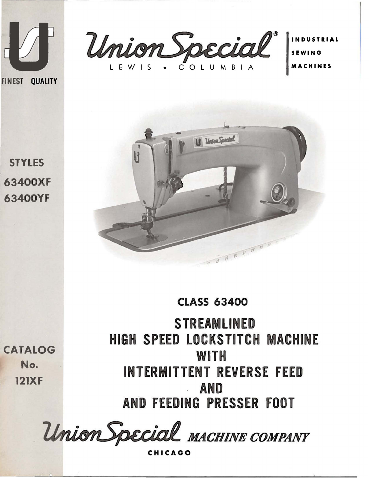
STYLES
63400XF
63400YF
LEWIS
•
COLUMBIA
MACHINES
CATALOG
No.
121XF
CLASS
STREAMLINED
HIGH
SPEED
LOCKSTITCH
INTERMITTENT
-
AND
FEEDING
II
to
d
If
63400
WITH
REVERSE
AND
PRESSER
II
MACHINE
FEED
FOOT
CHICAGO
Page 2
Here
are
Oil
for
Specifications
Union
Sewing
roleum
mended
machine
roleum
white
1.
mount.
roleum
high
mitters.
3.
used.
UN
Specification
oil, vis
s.
Specification
oil,
or
For
use
Specification
oil
Specification
quality
It
WherE>
ION
for
all
viscos
with a maxi
where freedom
, viscosity
grease
is
similar
No.
3 gr ease is
SPECIAL
SPECIFICATION
Viscosity
Flash
Pour
Col
Neutralization
Viscosity
(0
Compounding
Copper
"
Anline
*Used
S.S.U. at
(Min.)
(Max.)
or
A.S.T.M.
Index
& D
Min.)
Corrosion (Ma
No.
with
Buna N
174
cosi
ty
100
oiling
175 specifi
ity
100
mum
87 specifies a hi
300
100
for
to
commercial
NO. 174 175
l00°F
(Max
.) 3 1 3
No. (Ma
x.)
x.)
Rubb
Special
Machines
specif
ies
es
from
obta
inable,
90-125
350
20
0.10
85
None
1A
1 75-
225
Retainers
a high qual i
at
100°F.
on
a hi
gh
100°F
color
oil
staining is para-
gh
100°F.
N.L.G.I.,
90-125
350 350
0.10 0.10
None
175-225
seconds
applications
seconds at
A.S.T.M.
seconds at
specifies a general purpose
use in ball bearings and
not
er
"0"
ty
Recom-
high speed
quality
••
water
number
quality
tran
grease
No. 2 may
87
300-350
20
85
Non
1A
1 75-225
pet-
pet-
of
pet-
s-
No.
be
20
85
e
1A
..
NOTE
meeting above classification
essential. These
These additives mu
a
separate.
NOTE
shall
1: "fhe
1.
2. Rust
3.
4.
5.
nd
not
2: Oils
not
1.
2.
3. Lead soap additives
4.
use
may
Oxidation
inhibitor
Lubricity
Anti-oxidant
Film
strength
removable
containing
be
used at
Extreme press
Tackiness
Detergent
of non-corrosive additives in
include:
inhibitors
s
additives
s
additives
st
be
completely
by
wick
the
any
time
ure
or
s
additives-corro
adhesive addi
is
desirable
feeding
following
:
soluble in
nor sha
type
tiv
es
sive
but
ll
addi
the
®
oil
not
oil
they
tive
s
s
Page 3
(S
u p p l e m e n t
atalo
C
g N
to
o.
Catalo
121
g N
XF
o.
121
M )
INSTRUCTIO
ADJUSTING
LIST
Streamlin
63400
XF
AND
CLASS
Styl
FOR
OF
e d
OPERA
PARTS
63400
Locksti
e s
6 3
NS
400
T I
t c h
YF
NG
Copyri
Union
Rights
Special
R e
served
MACHINE
INDUSTRIAL
P r
Fir
s t
g
ht
by
COMPANY
SEWING
CHICAGO
int
d i n U
Ed
i t i
@
Ma
i n
on
19
7 2
chin
All
MACHINES
.S.
e
Countr
A .
Co.
i
es
October.
197
2
3
Page 4
IDENTIFICATION
OF
MACHINES
Each
the
machine.
numbers
Example:
only
minor
Style
number.
Styles
which
differs
"Class
This
junction
not
used
Opposite
number,
NOTE:
Adjusting
those
ions
B,
inCatalog
included
or
are
Union
Sty
have
one or
"Style 63400
changes
Example:
of
machines
from
63400
11
•
catalog
therewith.
on
Styles
the
description
When
ordering
column.
and
in
additional
Spe
cial
machine
le
numbers
more
XF".
are
made
are
letters
Special
in a standard
"Style
similar
lhe
style
APPLICATION
is a supplement
Only
those
parts
63400 A and B are
illustration
and
amount
operating
No.
121M
this
catalog
repair
parts
instructions
for
Styles63400
are
instructions
is
identified
classified
63400
in
construction
number,
to
Catalog
which
page,
required.
always
the
ones
that
pertain
by a Style
as
standard
suffixed,
Style
numbers
machine, a "Z"
XFZ".
in
that
OF
CATALOG
No.
are
used
illustrated
parts
are
use
for
Styles
A
and
that
are
specifically
number
and
but
never
contain
are
grouped
it
contains
121 M
and
on
Styles
listed
and
identified
the
part
number listed
63400
Brespectively.
different
to
on a name plate on
special.
contain
the
is
suffixed
under a class
no
should
63400
at
the
by
detail
XF
and
from
Styles
Styles
Standard
the
letter
to
letters.
be
XF
oack
number,
in
YF
are
The
onlyinstruct-
63400
Styl
lett
er " Z
"Z".
the
used
and
of
Wh
Standard
numb
Examp
in
con-
YF,
this
book.
en
er
l :
bu
par
the
second
similar
to
63400 A and
XF
and
YF.
e
".
t
t
This
herein.
this
class.
from
It
the
catalog
operator's
handwheel
Streamlined,
Feed,
justable
Thread
63400
Automatic
Hook
Tension.
XF
on
light
necessary.
bar
travel.
range 7 to
size,
pending
63400
YF
on
medium
tacking
inchneedle
Stitch
type
and
-
depending
applies
can
also
be
Reference
position
is
toward
Flat
the
Bed,
Lubrication,
Oil
Supply,
For
attaching
to
medium
The
reverse
Se
am
18
per
attachment
on
operation.
For
attaching
to
medium
are
necessary.
bar
travel.
range 7 to
size, attachment
on
operation.
specifically
applied
to
direction,
operator.
Lockstitch
Equipped
pockets
weight
Spec.
inch.
and
guide.
pockets
heavy
Seam
18
per
with
while
STYLES
Gauged
to
material,
feed
can
301-SSa-1.
Specify
Maximum
to
weight
The
reverse
Spec.
inch.
and
guide.
to
the
Standard
discretion
such
as
seated
OF
Machine,
Oil
to
right,
at
MACHINES
with
Supply,
with a Feeding
shirt
fronts
where
be
used
for
Type
stitches
per
recommended
shirt
fronts
and
material,
feed
can
301-SSa-1.
Specify
stitches
Maximum
Styles
some
the
Special
left,
machine.
Intermittent
Adjustable
Presser
and
similar
matching
back-tacking.
180
GXS
inch,
similar
where
be
used
Type
per
recommended
front,
Foot
plain
plies
or
thread
speed
plain
matching
for
180GXS
inch,
of
machines
Styles
back,
Operating
Reverse
Feed
and
seaming
and
back-tacking
1
9/64
180
GYS
size,
5500
seaming
back-tackin
or180
thread
speed
as
of
machines
etc.,
are
di
rection
and
Eccentric,
Rotary
operations
inch
needle.
needle
R.
type
P.M.
operations
plies
and
g. 1
GYS
size,
5500
R.
listed
in
given
of
Plain
Ad-
Needle
are
needle
Stitch
and
-
de-
back-
13/64
needle.
needle
P.M.
4
Page 5
NEEDLES
Each
number
The
size
blade,
number
label
Needle
The
description
Type
180
GXS
180
GYS
To
sample
on
label.
Selection
used.
stitch
Union
denotes
number,
measured
and
the
of
all
needles
Type
No.
have
needle,
A
complete
Thread
formation.
Special
the
kind
stamped
in
thousandths
size
number
packaged
180
GXS
and
sizes
Round
groove,
shank,
wide
chromium
Round
groove,
shank,
wide
plated -sizes
needle
or
orders
the
type
order
of
the
proper
should
pass
needle
of
has
shank,
on
the
of
represent
and
sold
or
180
GYS
available
round
angle
plated -sizes
round
angle
029,
032,
promptly
and
size
would
read:
needle
freely
through
both a type
point,
needle
an
are
length,
shank,
inch
by
are
across
the
complete
Union
recommended
listed
Description
point,
groove,
lockstitch,
struck groove,
029, 032, 036, 040, 044,
point,
groove,
lockstitch,
struck
036,
and
accurately
number
"1000
size
should
the
number
groove,
Special.
below.
040,
044,
should
Needles,
be
determined
needle
and a size
denotes
the
eye.
symbol,
for
and Siz
short
short
groove,
049,
filled,
be
forwarded.
Type
eye
finish
largest
Collectively,
which
Styles
es
length,
deep
length,
deep
054,
an
180
by
in
order
number.
and
other
The
diameter
the
is
given
63400
spot,
ball
XF
eye,
ball
and
049, 054,
ball
eye,
spot,
chromium
060.
empty
GXS,
the
to
package,
Use
description
Size
size
of
produce a good
typ
details.
of the
typ
on the
YF.
singl
point,
060.
singl
".
036".
thread
e
e
e
e
a
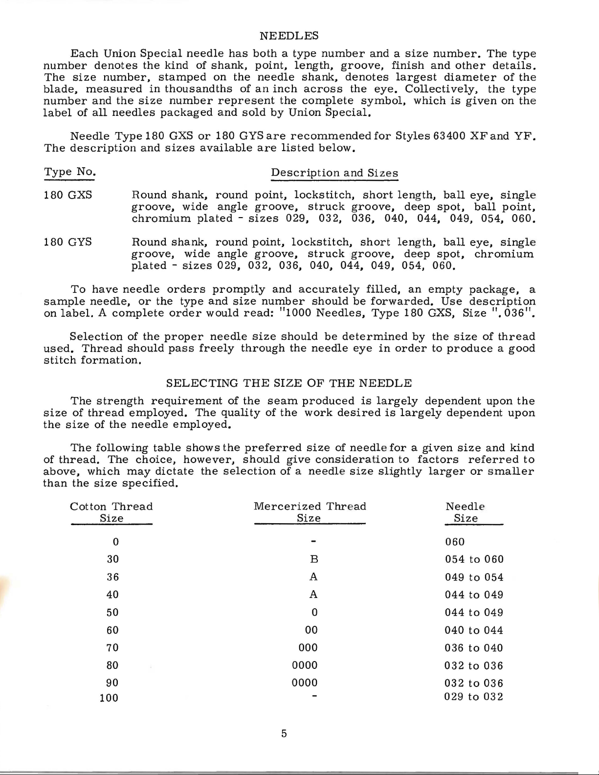
The
size
the
size
The
of
thread.
above,
than
Cotton
of
the
thread
which
strength
employed.
of
the
needle
following
The
choice,
may
size
specified.
Thread
Size
0
30
36
40
50
60
70
80
SELECTING
requirement
The
employed.
table
shows
however,
dictate
the
THE
of
the
quality
the
preferred
should
selection
Mercerized
SIZE
seam
of
the
give
OF
THE
produced
work
size
of
consideration
of a needle size
Thread
Size
B
A
A
0
00
000
0000
NEEDLE
is
largely
desired
is
largely
needle for a given
to
factors
slightly
dependent
dependent
size
referred
larger
or smaller
Needl
Size
060
054
to
049
to
044
to
044
to
040
to
036
to
032
to
upon
and
e
060
054
049
049
044
040
036
the
upon
kind
to
90
0000
100
5
032
029
to
to
036
032
Page 6
IDENTIFYING
PARTS
Where the
Parts
which
too
dist
Part
appear.
IMPORTANT!
OF
MACHINE
The
arrangement
replacement
The
exploded
Styles
Each
position.
their
view
listed
plate
On
part
being
Numbers
the
position
in
ordering
exploded
view
construction
small
inguish
numbers
for a complete
one
part
r e
present
ON
ALL
FOR
WHICH
of
parts
in
for
view
this
catalog and
Styles
plates
presents a sector
the
page
numbers,
opposite the
descriptions
shown.
in
the
first
of
the part
parts.
plate
in
Always
carries
permits,
catalog
from
the
another
same
ORDERS,
PART
IS
ORDERING
this
catalo
63400
at
the
Styles
of
the
machine,
illustration
and
column are
the
illustration.
use
the
a
reference
each
stamp
that
part, rega
PLEASE
ORDERED.
OF
REPAIR
g i s
XF
back,
to facilitate easy and
and
cov
63400
the
number
reference
Reference
part
number
number
part
is
stamp
ing
are identified
is
simil
ar
rdless
in appearance.
of
INCLUDEPARTNAME
PARTS
YF.
er
the
differenc
A a
nd B cover
parts
being aligned
will
be
found a listing
of
piec
numbers
es r e
only,
numbers should
listed
for
in the
each
ed
with
its
by letter
the
catalo
accurate
es
between the Sta
ed in
Catalog No.
as
in
quired
and
second
part
available
par t
g i n
which
AND
or de
numb
sy
mbol
they
STYLE
ring
e r .
ndard
121
M.
their assembled
of
the
par
ts
with
in
the
particular
merely indicate
never
b u
sed
column. Each
for s
ale.
s
of
Sub-assemblies,
or a solid
can
be
description
In
catalo
parts
in
the
Success in
Uni
on
Company,
to
the
line
box
furnished
of
the
those
g,
for the
cases
no spe
various
description,
Special
Ne
its subsidiaries
most approv
cific
the
Maximum efficiency
Genuine needl
parts are sta
g
uarantee
Prices
are
forwarded
of
are
mped
the hig
strictly
f.
which
on
the
for
repairs,
main
sub-assembly.
where a part
usage
machines
and,
if
U
SE
GENUINE
operation
edl
es
and
ed
scientific
and
es a
re
packaged
with
hest
quality
net
o.
b.
shipping
picture pla
will
necessary,
Repair
and
durability
the
cash
otherwise directed. A charge
are
sold
complete,
te.
are indicated
is
common
be
me
ntioned
are
not
NEEDLES
of these
Parts
authoriz
principles,
ar
with labels
Union
Speci
in
materials and wor
and
subject
point.
is
made
Component
by
to
in
the sam
e,
the diffe r e
AND
machin
as
furnished
ed distri
a
e assure
d.
mar
al trade
TERMS
to
Parc
el
to
cov
er the
or
by
separa
parts
indenting
all
of
the
description.
the
specific
nce
will
REPAIR
es
can
butors.
nd
are
ked
~
mark.
km
chan
ge wit
Po
st
shipment
post
te
the
of s
their
ma
part,
ub-assemblies,
descriptions
chines
are
covered
However,
be
usage
shown
will
in
the
PARTS
be
secured
by
the
They are
made
with
Union
designed
utmost
only
Special
. Ge
Each
ans
hout notice.
hip.
s ar e i
trade
All
nsured
age and i nsurance.
in a brack
which
unde r
by
wh
en the
be
mentioned
illustratio
with genuin
Machin
according
precision.
nuine
mark
rep
is
shipmen
unless
et
the
thi
n.
ai r
your
ts
s
e
e
6
Page 7

INSTALLING
CAUTION!
on
handwheel.
Before
carefully
packing
A
attaching
miscellaneous
Insert
the
upp
Includ
ing one bobbin
its clamp spring, one
a
nd
scr
e
ssenti
packed.
box,
bag
of
screw,
hinge
er
frame eyelet
ed also with each
ew,
four
al whe n s etting
When
Using
leaving factory,
After
the
following
PREPARATION
assembly
one
attachments
studs
wind
er
isolator
unpacking,
both
hands
each
the
machine
steps
parts,
extra
to
in
holes
(A,
Fig.
STANDARD
machine,
assembly,
knee
up
lifter
pads
the
DO
on
bed
Union
should
OF
MACHINE
consisting
bobbin,
the
bed
provided
2A).
the
assembly
and
clips,
machine.
NOT
is a box
machine
lift
castin
Special
and
be
two
plate,
ACCESSORIES
g,
accessories
follow
of one
hinge
is
for
them
of
and
and
one
machine
lift
machine
ed:
FOR
studs
packed
STANDARD
mounting frame,
its
rubber
machine
out
of
gently
INSTALLATION
frame
in
.
is
sewed
have
and
with
rear
been
thread
two
each
of
ACCESSORIES-
pad,
rest
box
by
placing
off,
inspected
removed
eyelet,
screws
machine.
cloth
bed
plate.
one
oil
drain
positioning spring
pin.
These
one
from
one
eyelet
for
holding
Assemble
-containjar
parts
hand
and
the
and
are
Lockstitch
t
he
be d
plate
On
a s
cu
t-out
throu
over right
th
e r
nuts lig
1/16
tai
ning pl
of the
as
show
mu
st
with
gh
left
eta
ining plate (21393
htly.
Pl
a ce sewing head
inch clea
board
Tip
ma chine ba ck
n.
not bind.
i s
uitabl
the
hin
ge pad a
hin
ge
r ance
ate s m a
and tighten
All
end play
ma
chin
es
FL
USH
MACHINE
e t
ableboard,
hin
ge lugs
nd tighten
pa d;
insert
between
rtly
upward
against the rest pin, a
of the
TABLE
are
install
with
the
MOUNTING
place
to
the rear (Fi
round head
R)
to
in
the
frame mountin
the
with a hamm
locking nuts secu
cross
ed
top
of
machine mounting
securely. Ass
outside
cloth
shaft should
TOPS
in
tabl
the
FRAME INSTALLATION
g.
wood
front of
pla
te edge and the
er
rely.
m a
1).
scr
g, a
to
nd ass
tops,
chine
Insert
emble
ew
pa n
nd
ins
be
prepared
mounting
frame
the
bed
positioning
and
tighten
section,
after
ure
a g
mble the kn
taken
up
(21393
countersunk
being
frame
ood
by the
with
frame.
N)
spring
securely.
as
shown, and
sure
sides,
grip
on
ee
cone
cut
-out,
in
the
wood
there
rap
the
press
bearings,
so that
machine
scr
ew
(63474
Assembl
snug up
is a
the
underside
assembly
A)
e
bout
r e -
but
7
Page 8

MACHINE
MOUNTING
FRAME
INSTALLATION
(Continued)
Before
lifter
maximum
within
raises
located
in
the
pulley
the
under
121M.
al
"THREAD
rod
the
approximately
The
directly
operation.
mechanism
of
belt
to
"Winding
These
Thread
requirements,
the
machine
should
lift
head.
bobbin
the
wind
machines
machine
CONTROL".
be
of
the
This
winder
in
The
to
winder,
the
the
adjusted.
presser
may
5/16
front
base
be
moved
when
bobbin.
Bobbin",
are
as
has
been
is
put
The
bar
be
done
inch.
should
of
the
sewing
of
the
winder
closer
in
operation,
Regulation
under
equipped
indicated
enlarged
Needle
into
production, the
left
stop
and
its
by
setting
BOBBIN
be
secured
machine
has
to
or
and
OPERA
BELTS
to
use
THREADING
in
Fig.
for
is
threaded
screw
parts
the
WINDER
to
the
belt
two
elongated
farther
should
operation
TOR'S
eith
er # 1
2A.
Check
clarity
from
do
bell
(22597
not
stop
table
and
away
exert
of
INSTRUCTIONS,
"Vee"
spring
and
left
crank
F)
interfere
screw
top
so
will
bear
attaching
from
only
enough
the
bobbin
or
threading
described
to
right.
should
(21665
with the
so
that
that
against
holes,
belt
winder
round
under
J)
be
set
moving
the
presser
its
pull
the
which
as
needed.
pressure
is
in
belts.
with
paragraph
of
the
knee
so
that
parts
bar
ey
will
belt
when
allow
The
agains
described
Catalog
dimension-
No.
Lhe
be
t
on
- 21664
Fig.
1
8
/
,/
6
3476C
Page 9

OILING
CAUTION!
the
reservoir
Fill
oil
is
be
added
straight
in
the
Oil
left
in
The
of
the
arrow
the
flow
It
long
period,
parts.
Run
machine
speed
Oil
has
main
at
maximum
when
mineral
main
may
the
oil
quantity
machine
must
reservoir
reservoir.
be
reservoir
level
needle
oil
drained
of
just
be
of a Saybolt
oil
below
(counterclockwise)
of
oil.
is
recommended
be
lubricated
After
operation
oiling,
slowly
can
replace
for
then
been
filled
at
plug
when
is
in
yellow
This
from
cover.
supplied
the
increases
that a new
by
several
be
expected
drained
before
screw
needle
is
equivalent
main
to
cloth
removing
head
minutes
from
starting
(B,
is
in
band
marked
viscosity
reservoir
the
hook
plate.
the
oil
machine,
cover
without
the
to
Fig.
yellow
of
to
is
Turning
flow
or
the
as
no
to
distribute
main
operate.
2A)
and
band
"LOW".
90
to
125
Union
by
removing
controlled
and
in a clockwise
one
that
head
cover
further
damage.
reservoir
check
oil
marked
Use a stainless
seconds
Special
specification
plug
by
dial
the
dial
in
has
been
and
hand
oil
to
oiling
the
before
level
"FULL".
at
100°
screw
located
the
direction
direction
out
of
oiling
will
various
shipment
at
gauge
Oil
water-white
Fahrenheit
No.
located
on
the
decreases
service
all
the
be
required.
parts.
and
(C);
should
175.
on
the
front
of
the
for
moving
Full
a
WRAP
ROTARY
2
THEN
POST
1/2
THREAD
TENSION
TURNS
THREAD
EYELET
AROUND
DISC
CLOCKWISE
TENSION
Fig.
2A
9
Page 10

The
adjusting
instructions
63400 A and B covered
INSTRUCTIONS
for
Styles
in
Catalog
No.
FOR
63400
121 M,
MECHANICS
XF
and
YF
with
the
additions
are
the
same
as
follows:
as
for
Styl
es
FEED
both
DOG
The
feed
directions,
approximately
CHANGING
To
change
adjusting
sulting
reverse.
NOTE:
at
screw
in
more
Tighten
After
the
front
Fig.
it
may
require
feed,
feed
feed,
check
will
refer
affect
SETTING
dog
must
across
3/64
THE
STITCH
the
stitch
(B).
stitches
locknut
setting
and
28
adjustments
the
stitches
the
to
paragraph
be
the
inch
above
length,
Turning
per
the
back
per
travel
centered
line
of
the
in
the
feed
throat
as
LENGTH
inch)
(A)
stitch
in
both
loosen
the
screw
after
length,
the
SETTING
NOTE:
knurled
and
turning
obtaining
make
forward
THE
The
on
the
the
reverse
as
the
Set the
both
the
forwa
edusingheavypaperorv
12
stitches
of
both
mechanisms.
inch
in
both
of
the
on
"CHANGING
other.
To
feed
slots
well
as
plate
at
locknut
clockwise
the
the
sure
and
REVERSE
reverse
reverse
feed
control
stitch
r d
and
per
inch
directions,
chan
THE
STITCH LENGTH".
ofthe
in
the
the
top
decreases
screw
desired
the
reverse
feed
feed
control
will
lev
er is
length
r eve
e
on the
Aft
er
be
ge the
(A,
throat
line
of
Fig
of
its
plate
feed.
stroke.
. 28)
the
counterclockwise
stitch
feed
FEED
is
length.
dog
has
feed
direction.
MECHANISM
actuated
lever
continue
held
at 12
rse feed.
ry lig
ht
forward
making an
cause
stitch
to
down.
stitches
This
cardboard.
and
adjustm
an
adju
length
and
leveled
It
should
and
turn
stitch
by
length
equal
clearance
pushing down
(C, F
ig
op erate
per
can
be
To
revers
ent
stme
nt
of the
rise
the
feed
(re-
acts
the
. 28)
as
and
long
inch,
check-
obtain
e
feed,
to
one
to
one
forward
in
on
The
reverse
adjusting
This
back
screw
move
the
can
be
against
(B).
the
control
reverse
decrease
after
length
NOTE:
making an adjustment
in
both dire
Once
been
in
stitch
under
reverse fe
s
hould get
of s
titches in
CAUTION!
control
move
ag
ain
feed
the stit
ch
accomplished
the
rest
When
the
lever (A)
fe
ed
the
travel.
ctions.
the
forward
set
at 12
length
"Cha
ngi
ed
will
approx
bot
On
machin
r e
vers
this
lev
er before tippi ng mach
s t
the
rest pin.
travel
control
pin
machine
travel
Retighten
stitches
can
ng
The
not have
imate
h d
ire
es
e fe
ed
can
be chang
by
and
towa
or
lever
tipping
away
(A,
F ig.
the machine
loosening clamp
is
in
this pos
r d
you
to
incr ea
from
clamp scre
and
check the
and
be
revers
per
ma
de
Stitch
to
be a
inch,
e feed
a
chan
as
described
Length", the
dju
sted, y
ly the sam e number
ctions.
equipped
lev
er
wit
h a
(A,
F ig. 30) r e -
treadle
ine
ed
29).
ition
you
w (B)
stitch
has
back
by
se
to
ge
ou
Fig. 29
10
Page 11

SETTING
If
equal
titch
s
ns
i
as
length
ide
the
follows:
THE
REVERSE
stitch length,
control
machine.
lever,
The
FEED
forward
adjustment
feed
linkage
MECHANISM
and
reverse
should
is
pre-set
(Continued)
cannot
be
at
made
the
be
factory
obtained
to
the
feed
and
by
adjusting
linkage
may
be
the
located
check
ed
Fig.
verse
and
screw
adjusting screw.
ADJUSTING
feed
adjust
(B)
lever
the
stop screw
in
this
THE
30
(A,
po
wh en
FE
Fig.
sit
EDING
30)
(B.
ion
with
reverse feed
PRESSER
remove
cover.
stitches
ing
move
plunger
er
above
Retighten
and
voir
can
feed
scribed
hold
Fig.
locknut
Drain
screw
of
replace
cover.
be
On
down
30)
is
FOOT
machine
the
bottom
Set
the
machine
per
inch.
(A,
the
lever
screw
the
made
control
earlier.
machines equipped wit
the
to
(C).
actuated
stitch
(B).
(C)
bottom
holding
the
bottom
Now
to
lev
reverse feed control
stop against
This
by
of
oil
reservoir
at
Loosen
Fig.
is
31)
regulator
so
the
23/32
of
the
screw
reser-
adjustment
the
revers
er as de -
the bed castin
is
to prevent
s tepping
hold-
cent-
base.
and
zero
and
inch
(A)
e
h a treadle contr
l e v
er
dam
age
on
the tr
eadle
F ig . 31
(C,
Fig
g. L ock
to
the feed
.
ol
. 28)
stop
re-
Adjust
(3)
threads
Ba ck o
r esting fla t on
jus
ting li
Tighten
Loosen s crew (E, F
pr
ess
er b
li
fte r lever.
S
et
above the thro
machine
screw in
or
left,
tighten the
spring
i
nch
space between
is
in alignment with the nee
the p
are
ff stop screw
nes
on
loc
k nut (D).
ar
(G) dep
the p
resser
a t
back
the lift
the
as requir
ag
prop
locknut
resser spring
visible
the
thr
the
presser
ress
bar
plate
ainst the
er
lev
er s
to
ed
to reset the
the guide
above
(B,
oat
plat and
ig.
presser
connection
seat (See
rest
er b e
ll
ett
ing
for
lock the
dle
regulato
the
bed casti
Fig.
16A)
foot
bottom, line
16A)
in presser bar guid
foot
Fig.
pin,
crank
and
(61468
the
stop
presser
press
before
r (A, F ig .
ng.
in fee
feed
lift
(A, Fig.
loosening the
presser
scr
er
tightening screw
din
g p
dog
down, adjust stop
up
er le ver and r
16B)
16B).
ew in pla
bar guide
11
F).
bar
Th
By
bar
connection,
16A)
resser foo
with
s o its t
is
turning the s
connection
ce.
s o tha t a
the
e (F ),
etight
op sur face i s 5
is
accomplished
locknut
Relea
(F ,
Fig.
(E).
cen
s e
be sure th
pproximately three
t.
With the presser foot
nut
(C) unt
terline
whil
e h
oldi
n screw (E
and reloca
top
s crew
is
accompli
pressur
16A)
allow
il
of
the nee
ng
down
). Release
1/8 inch
by
tippin
ting the stop
to the
she
e
on pres
ing a 1/16
e p
resser foo
the a
g the
rig
d.
d-
dle.
on
es
ht
Re
s e r
-
t
Page 12

ADJUSTING
THE
FEEDING
PRESSER
FOOT
(Continu
ed)
presser
between
stop
screw
mum
of
spring
the
{F)
1/64
Fig.
top
in
inch
(B)
and
of
the
feeding
on
16A
adjusting nut
yoke
throat
(E)
foot
plate
and
so
top
that
when
er
and
presser
of
Lock
(A)
on
of
spring
presser
foot
Remove
spring
adjust
the
in
presser
foot
is
lifted
(B)
foot
needle
position
(B)
bottom
with
12
nut
stop
is
slot
foot
with
(A,
of
the
nut
pushed
will
with
and
the
slides
feed
Fig.
feeding
(C)
forward,
not
locknut
adjust
feed
rearward
dog
Fi
g.
18C)
so
that
touch
to
dog
down.
16B
and
presser
when
the
(D).
45/64
down.
press-
foot
the
the
rear
needle.
Replace
inch
Adjust
a
maxi-
Page 13

ADJUSTING
Lift
feeding
Should
loosen
18C)
adjustment
screw
as
required
THE
in
FEEDING
presser
be
necessary,
bottom
to
obtain
foot
of
presser
proper
PRESSER
and
check
remove
foot
position.
FOOT
to
see
shank
(Continued)
if
bottom
the
presser
to
reposition
Retighten
is
foot
screw.
parallel
from
leveling
to
the
spring
throat
machine
(G,
plat
Fi
e .
and
g.
THREAD
Set
(underside)
(See
Set
1
I 64
thread
the
thread
spring
check
thread
Thread
thread 2 1/2
tary
tension
Set
spring
bottom
is
at
CONTROL
needle
Fig.
16A).
tension
inch
running from the
pull-up
not
spring
pull-up
machine
check
overthrows
of
check
speed.
Fig.
of
clearance
threaded
times
disc.
18C
thread
bracket
post
bracket.
1/2
inch
bracket
as
shown.
clockwise
spring tension
threadline
spring
pull-up
to
top
eyelet
between
rotary
(See
above
(See
motion
of
so
with
Fig.
Wind
so
when
bracket
cloth
there
it
and
tension
the
18D).
bottom
Fig.
around
that
slightly
machine
(H,
plate
is
the
to
check
Set
of
18E).
needle
ro-
check
at
Fi
g. 16A) 4 19 I 3 2
a
Fig.
inches
18D
from
bottom
Set
light
being
may
to
feed
needle
as
possible to
sure
When
have
the
and
bottom
produce
check
sewing various
to
bottom
be
changed
spring
ply
faster
thread
a
is
acting
materials,
to
get
and
tension
good
properly.
good
ply
vice-versa.
as
stitch
the
pressure
matching.
13
of
the
Increasing
Fig.
feeding
the
18E
foot
presser
pressure
spring
will
tend
Page 14

14
Page 15

T
he
p a r
ts illu
pr
esent the p arts that a r e used o
U
se Catal
strated
og No. 1
21 M (Styl
on the oppo
nStyles 6:34
es 634
site page and
00
XF
00
A or B) f
on page
and YF,
or all parts
16 and des
but
not
used on
not illu
cr ib
ed
Styles 6:34
strate
on this page an
d or
00
A or
described
d page 1
Brespectiv
in this c a
7, re-
ely .
talo
g.
Hefere nc e n
indicate they are
P a
R
No.
10
11
12
13
14
15
16
17
l B
19
20
21
22
23
24
2
26
27
28
29
30
31
32
33
34
34
35
36
37
38
39
40
4
41
42
43
44
45
46
47
48
49
50
51
52
53
54
55
56
57
58
f.
1
2
3
4
5
6
7
8
9
A
0A
rt
N
o.
6
:345
7 M
3457
6
612
57 G
51257 G
6:3957
21
390 BE
57 WD
57
57 WB
225
64 B
634 71
634
71
634
70 s
90
2935A
1
639
92 A
HS
24
22513
639 70 A
29475 BE
660-
6
3992
225
60
349
2
6
349
2 B
6
634 53 N
614
92 T
49
2 s
61
92
61 4
6
349
2 C
612
92 c
61405 AA
61424 AA-063
63420
420
63
63430 u
227
85
22560 B
63430 T
56330
634
30
63430 s
99
227
73 A
56
33
0 AS
56330 AJ
56330
56330
604
529
30 AC
5 1430 F
56330
4
107
1 G
56330 AD
343
0 v
6
61
405 AB
61
424 AB-063
63459 B
22570
73 c
umbers tha
com po
nen
L
A
we
A
C
269 A
G
H
-4
J
H
AP
w
AB
AG
AF
AU
t ar e
insi
t pa r
de a bracket or box on the pi
ts
of a
com
Lock N
Stop Nut
P r esser Spri
Presser
P r
Ni
L ow
Sc
Scr
T
Screw
Screw, fo r t
Th r
Rotary
Fee
T
Presser Foo
Presser Foot,
Feed Do
T
Pres se r Ba r Guide
ut-------------------------------------
--------------------------------------------------------
Bar ----------------------------------------------------
esser Bar
pp
er Sp ring A
Scr
ew, f
Ni
ppe
per Sp
Nip
Screw
Nip
pe
Ni
pper Sp
er
Need
r ew, f
or nipper spr
ew, fo r
ensi
on P o
----------------
ea
d P
ull-up
Needle
Quad
Te
nsi
Set Scr
Te
ns i
Tensi
Ta
ke
-up Spr ing---
Felt Washer
R
otary
Tensi
Te
ns i
Tensi
d Dog, 22
hroat
P l
ate
Yo
ke
Sc
Screw
Presse
Bu
Presser
63420
Presse
6
34
20 H
Hinge Pin
Sc
r ew,
Hinge Spr ing
Hinge Pin-------
Regula
Li
nk Hin
Scre
w, f
Chain Cutt
Nu
t---------------------
as
her
W
L
oc
k N
Compression
Re
gula ting NuL
hr
g,
oa t Pla te , . 063 inch need
Scr e w
Scr
ew
cture
plete part
ng Regulator a
Bushi
or
r Spring
rin
------------------------------------------------------
r Ba se--
r ing Mounti
le Thread Ey
tension assembly------------------------
st Socket
hre
ad pull-up
Tension
Ring-------------------------------------on
P os t
on
P os t -
on
Release
Tensi
on
Release Washer
on
Spr
on Nut
tee
, . 063 inch n
t, for w
for
-----------------------r e \v
--------------------------------------------------
--------------------------------------------------
r F
oot Link
shing------------------------
F.oot B
3-------------
r F
ool Bot
--------------------------------------------------Screw----------------------------------
for
hin
ting Scre
ge Screw -------------------------------------------or cha
ing Kn
-----------------------------------------------------
ut---------------
22
Leeth per i n
-----------------
---------------------------------------------------
or
assembly
Descripti
nd
Bu h ing
ng,
ssembly--------------nippe r spring
Br acket
ew --- - -
ing
lower--------------------------------------
------------------------------------------------
g P la te - -
-----------------------------------------------
ing asse
Eyelet ---
Soc
ket
----------------------------------------------P in
---------------------on Disc
----------------------------------------------
----------------------------------------------
th per inc h, f
ide
narr
, m
otto
tom, m
ge spring
---------------------------------------------
----
w------------------------------
in
cut
ife, marke
Spr
ing
-----------------------------------------------
-----------------
--------------------------------------
----------------------------------------
ng Brack
elet --------------------------------------
mbly
------------------------------------
-
----------------------------------------br a c
ket
--------------------ssembly
----------------------------------------
------------------------------------------
-----
-----------------------------------
feed combination---------------------------
ow
m ,
- - -
----------------------------------------
- -
-----------------------------------
or
eedle hol
feed comb
ark
ed
marked "BV",
-
-------------------------------------arked "B
- -
------------------------------------
-------------------
ti ng
knife
d "
-
-----------------
-
----------------------------------------
-------------
ch,
for nar r
le hol
-
---------------------------
plate and ha ve indent
.
on
-----------------------------
-
--------------------------
et-------------------------------
---------------------------------
--------------
----------------------------------
----------------------------------
-
--------------------------
wid
e feed comb
e,
for wid e
ination---------------------
-
---------
"C"
-------------------------------
U", for
------------------
D"
------------------------------
ow
e, f
or narrow
-
-----------------------------
fee
-
-----------------------
for
pr e
pre
-
----------------------
fe ed
comb
-
------------------
-
--------------
-
---------
-
--------------------
-
------------
ina
tion--------------
d c
omb
ination
-
--------------------
sser fool
s ser fool No.
-
--------------------
-
-----------------
ination
feed co
No.
-
-
--------------
-
--------------
------------
mbi nation
ed descrip
-
--------
-
-------
-------
-
---------
-----
-
--------
---1
tions
Am
Rc
- - 1
- 1
- 1
---1
---
- 1
- 1
---1
- - 1
,
t.
q,
1
1
1
1
1
1
1
1
1
1
1
1
1
1
1
1
1
1
1
1
1
1
1
1
1
2
1
1
1
1
1
1
1
2
1
1
1
1
1
1
1
1
1
1
1
1
1
1
1
15
Page 16

16
Page 17

REVERSE
FEED
MECHANISM
PARTS
Ref.
No.
*1
*2
3
4
5
6
7
8
9
10
11
12
13
14
15
16
17
18
19
20
21
22
23
24
25
26
27
28
29
30
31
32
:33
34
35
36
37
38
39
40
41
42
43
44
45
46
47
48
49
50
51
52
53
54
55
56
57
58 97
59
60
61
62 6
63
Part
No.
421
660-264
63444
64 B
64 A
22517
63444
22894
660-206
63444
93
22539
86
63444
63444
22570
39552
63432
22894
G61447
G6144
531
6343
22
586
G61436
6343
G61
4:3
G614:
36
22830
63433 B
99284
96
505
634
34
88
88 D
G6
1439
2277 5 A
12934 A
G61436
99285
63436
22519
29126
61438
88
660-22
63437
95
63432
2289
660-207
99282
99283
63444
22894
22894
12 4 6 L -
63
44
660-206
6
3444
343
22651
D-28
A
c
w
D
M
E
F
A
c
H
w
8
2 F
5
6 A
C
B
A
B
u
II
E F
A
c
H
4 w
G
p
u
9
B
2 G
CD
5
-5
1/
-
----
------
-
----
-----
-
-----
------
- - -
-
----
-----
-
----
---
Amt.
Req.
1
2
1
1
1
1
1
2
1
1
1
1
2
1
1
l
2
1
2
1
1
2
1
1
1
1
1
1
1
1
1
1
1
1
1
1
1
1
1
1
1
1
1
1
1
1
1
2
1
2
1
1
1
1
1
1
2
1
1
1
1
2
Description
Treadle
"S"
Reverse
C
ollar,
"0"
Re
Plug
Screw,
Reverse
Reverse
Thrust
Collar,
Reverse
Collar,
Feed
Feed
Feed
Reverse
Screw,
Reverse
Screw,
Link
Feed
Screw,
Feed Dog H
Screw,
Nut,
Reverse
Reverse
Reverse
Feed
Thrust
"O"
Adjusting Screw, for adjus
Lock
Reverse
2
Screw,
Reverse Feed
"0"
Reverse
Reverse
Screw, for
22653
Chain,
Hook,
Feed
Lock
Stop
Screw,
Clamp
for
Set
Screw
Ring,
verse
Feed
Screw
Screw,
for
Feed
Feed
Screw
Washer,
right,
Set
Screw
Feed
left,
Screw
Driving Shaft
Plug
Screw------------------
Rocker
Rock
F e
Sliding Block---------
for
Feed
for left
Pin, for
Bar
Set
Screw
feed
for feed dog
for
reverse
Feed
Fe d Rock
Fe d Shaft
Clamp
Driving Eccen
Connecting Rod--------------
Set
Needle
Feed
Driving Eccentric--------------
Set
Screw
Collar,
Set
Screw
Rin
g,
Nut, for
Feed
Set
Screw
Spot Screw
Dr
ive Pin-------------------------------
for
Rin
g, f
Feed
Feed Shaft
D-6)------------------
28 inches
for
treadle
Foot
Control
Nut,
for
stop
foot
Scr
ew
reverse
for
-----------------------------------------------------reverse
---------------------------------------------
---------------
er
ed
sliding
----------------------------------------------
older
Screw
for
reverse
or
feed driving s haft sprock
------------------------------------------------
---------------------------------------------------
reverse
Control
for
reverse feed
Control
Shaft
for right
for
reverse feed shaft
---------------------------------------------------
Shaft Ret
for
reverse
----------------------------------------
---------------
Shaft
-----------------------------------------
Rocker,
block (u
Lever
reverse
reverse feed roc
---------------------------------------------------
dog
holde
Support----------------------
feed
Rocker Lin
er
--------------------tr ic Asse
Screw
------------------------
Bear
---------------------left,
--------------------------
reverse fe
adjust
Hand
Control Operating Lever------------------------
---------------------------------------------------
-------------------------------------------------feed stit
Stitch
rever
se
Control Sha
long-------------------------------------
chain---------------------------------------
screw
control
feed
control
feed
Shaft
feed
control
Connecting Link-----------------------------
Lever, right
rever
urn
feed sha
with dri ve crank
Link----
feed shaft lever
r s
uppor
hold
er s upport - ----
rocker link s
k----------------------------------------
Link Stud------------------------------------
Le ve
r, left
ing
------------------------------------------
for
r eve r
ed sha
ing scre
Control Flange-------------------------
feed s
ft---------------------------------------
----------
Operatin
operating lev
control
Rocker
shaft
Spring
-
--------------------------------------
----
s ed i n pl ac e of s c r ew
- - -
t - -
mbly
se feed s ha ft
tin
g s
w-----------------
ch control flan
titch
g Le ve
-----------
shaft------------------------------
shaft
Lever--------------------------
---------------------------------
connect
----------------------------------
se
feed shaft lever
----------------------------
ft r etur n s
-
- - -
--------------------------
----------------------------
-----------------------------
ker
link-----------------------------
----------------------------------
tud
------------------------------------
---------------------------------
-
-------------------------------
ft
----------------------------------
titch
1 ng
control
- - -
--------------------------------et
----
-------------------------------
r------------------------
-
-------------------------
er
-----------------------
---------------------------
ing
link-----------
return
--------------------------
- -
(used
spring------------------
pring--------------------
- -
-------------No.
--------------------
--
---------------------------
-----------------------
-
--------------------------
-
----------------------
- - - - - - -
-
----------------------------
--------------------------
- - -
----------------------
th
-------------------------
-
-
ge
-----------------------
fl a ng
e---------
in pla
-
---------
-------------------
88
------------------
------------------
-------------------
----------
ce
of scr w
-
-
-----------
13)------
--
- - -
-
-----------
--------
-
- - -
-
- - -
-------
------
-
------
No.
'
~
Not furnished
able
for oper a
with
tin
g the r e
m a
chine,
ava
verse feed
ila
bl e
as
an
mechanism.
extra se
nd and
cha
r ge
17
item, wher e a
foot
treadle
is d
esi
r-
Page 18

BOOST
PRODUCTION
WITH
WORK
UNION
THESE
AIDS
SPECIAL
FROM
PNEUMATIC
convent
sci
ssor-action mechan is m
ve
positi
AIR
FABRIC
signed
to remove
kn
it
mater
area.
Style
ional
cui.
for
ials as
Style
Class
curls
2899
CHAIN-CUTTER
Class
2899
UNCURLER-This
39500
from
fabr
B-1
39500
and
thai
A-1
machines, uses
top and
bottom
ic passes
- for
39600
is a durable
makes a clean
...
unit, de-
plies
through
use
on
air
jets
of
flat
sewing
PNEUMATIC
operated
machines
simply by
CHAIN
small
for
36200
foot
allows
CUTTER-
pneumatic
installation
Flalseamers.
FOOT
lifter for
the
knee-touch
cha
as an accessory unot o
LIFTER-The
use
operator
ing an
The above
1n
cutter
Style 2899A-6
on Class
to raose
actuating
photo
that is available
the
swit
shows
rl
39500
Class
air-
loot
ch .
the
KNIFE
GRINDER
type knoves,
nates defective garment s caused
sharpens
is
simple and easy to operate,
straight
by
dull knives.
®
u
IIN!IT QUA
LIIY
M A
cHINE
wheel
msuring
ELECTRONIC
to
move
better
NEEDLE
the
needle
control, unif
up
or
orm
POSITIONERS
down
...
quality
AMCO
or
angle
elimi-
this
allows
and increased
HEAT
DISPELLER-Un
unit
(arrow) is an effective means
oil
temperature
qu
ires o
l.
eliminate
the
operator to keep
producllon.
where heavy duty service re-
Style
2899
E-1
the
necessity
ion Spec o
of reaching
both
hands on the
al's
lor
for
the hand-
auxiliary
reducing
work
,
Page 19

Helpful,
ci
ent
types
machine
Sales
Promotion
esting,
obligation
illustrated
authontative information
of
equi
sewed
are the
pment
article
Department.
bulletins
follow
for
is
ava
ilable
Among
that
ing:
on
the
mak
from
are
most
ing
virtually
Union
the
many inter
available without
eff
any
Special'
i-
s
-
HERE
ARE
HELPFU
L
No.
240, "Men's, Women's, C!'lildren's
No.
249,
"Rainwear"
No. 250,
No.
No.
No. 253,
No.
No.
No.
No.
No.
No.
No.
No.
No.
No.
No.
No.
No.
No.
No.
No.
No.
No.
No.
No. 1100,
No.
"Columbia
mg Mac
No
. 15
"Men's
251,
"Service
252, "Men's
"Overall
254,
"Men's Knit
256,
"Knit
259,
"Men's
260,
"Work
262,
"Cotton, Burl
263,
"Men's Clothing
264,
"Men's
265,
"Women's Wear"
266,
"Women's
26
7, "Corsets, Girdles, Brassieres"
268,
"Children's
269, "Mattresses,
Upholstery"
271, "Awnings
273,
"Curtains & Drapes"
610,
"Kiipp-it"
710,
"MCS
730, "MCS
Hemmer"
740, "MCS
750,
"Fusing
stitch,
1105,
hin
00, "Alteration
Oute
Bags"
ForMation
Automat
Automat
"Lewis
"Button
Bl i
ndstitch,
es"
Dress
Shirts"
Shirts
and
Shorts
and Pajamas"
s, Coveralls, and Dungarees"
Underwear"
rwear"
Sports Shi
Glove
s"
ap,
Jute
"
Women's,
Wear
And High
Wear"
Slip Covers,
, Canopie
ic Dual
ic Ri
Press
es"
Blindst
Machi
itch, Cha
nes"
Sewers-
Saddle
Depart
Pants"
rts"
, and
Multiwall
Children
s,
Uni
Ticket Tacker
's
Jackets"
Fashion"
Furnitur
Tents, Tarps"
t"
Underfront
b-Knit
Cuff
insti
tch,
Stitch,
ment
and Tie
Machines"
Footwear"
Pap
e
Shirt
Machine"
Lock
s"
Clo
BULLETI
TO HEL
SEWI
er
·
s-
NG P
NS
P
and
YOU
ROB
CATALOGS
SOLV
LEM
E
S
®
Page 20

WORLD'S
FINEST
QUALITY
*
INDUSTRIAL
SEWING
MACHINES
UNION
facilities throughout the
aid
you
SPECIAL
maintains sales
and
world. These offices
in
the selection of the right sewing
equipment for your particular operation. Union
and
Special representatives
tory trained
promptly
tion, there
and
and
is
a Union Special Representative to
serve you. Check with
ATLANTA,
BOSTON, MASS.
CHICAGO,
DALLAS,
LOS ANGELES, CAL.
NEW
PHILADELPHIA,
GA.
ILL.
TEXAS
YORK, N.
Y.
PA.
are
efficiently. Whatever your loca-
service men
able
to serve your needs
him
today.
MONTREAL, CANADA
TORONTO,
BRUSSELS, BELGIUM
LEICESTER,
LONDON,
PARIS, FRANCE
STUTTGART, GERMANY
service
will
are
fac-
CANADA
ENGLAND
ENGLAND
400
Representatives
MACHI
N.
FRANKLIN
industrial
and
distributors
cities throughout
NE
COMPANY
ST.,
CHICAGO,
In
all Important
the
world.
ILL.
60610
 Loading...