

Page 1
INDUSTRIAL
SEWING
®
EST
QUALITY
STYLES
63400X
63400Y
63400KX
63400KY
C 0 L U M B I
A®
MACHINES
ATALOG
No.
121KX
Second
Edition
CL
ASS
S
TREAMLINED
HIGH SPEED
LOCKSTIT
WITH
INTERMITTENT
UNION SPECIAL
63400
CH
REVERS
MACHINES
FEED
CORPORATION
C H
ICAGO
Page 2
(Supplement
Catalog
to
No.
Catalog
INSTRUCTIONS
FOR
121
KX
No.
121
M)
ADJUSTING
LIST
Streamlined
63400
634
00
Second
AND
OF
CLASS
Styles
X
KX
OPERATING
PARTS
63400
Lockstitch
63400
63400
Edition
Y
KY
Copyright
1969
by
Union
Rights
Specia
Reserved
1
Corporation
in
All
Countries
UNION SPECIAL CORPORATION
INDUSTRIAL
Print
SEWING
CHIC
e d
in
2
A
MACHINES
GO
U.
S.
A .
July.
1977
Page 3
IDENTIFICATION
OF
MACHINES
Each
on
the
machine.
Style
numbers
Example:
minor
Style
changes
number.
Styles
which
63400
differs
11
•
This
junction
KY,
book.
the
therewith.
but
not
For
63400 X and
Opposite
number,
NOTE:
description,
When
column.
Adjusting
similarto
instructions
and
B,
or
KX, Y
and
UNION
have
"Style
are
Example:
of
machines
from
catalog
used
clarity,
the
ordering
and
those
included
are
additional
KY.
SPECIAL
Style
one
63400
made
machine
numbers
or
more
X".
Special
in
a
"Style
similar
the
style
number,
APPLICATION
is a supplement
Only
on
certain
KX, Y
Styles
and
those
63400 A or B are
63400 A or B parts
KY
illustration
and
amount
repair
operating
inCatalog
in
this
instructions
No.
catalog
instructions
is
are
letters
Style
standard
63400
in
construction
to
parts
which
parts.
page,
required.
parts
always
121M
are
identified
classified
suffixed,
numbers
machine,
XZ
".
by a Style
as
but
contain
a"
are
in
that
it
contains
OF
CATALOG
Catalog
are
No.
used
121 M
illustrated
are
parts
use
for
are
the
Styles
identified
forStyles63400A
the
ones
that
that
pertain
specifically
number
standard
never
and
contain
the
Z"
is
suffixed
grouped
no
letters.
and
should
on
Styles
and
shown
63400 X and
listed
in
phantom
by
part
number
63400 X and
and
Brespectively.
are
different
on a name
special.
the
letter
letter
"Z
to
".
the
When
under a class
Example:
be
used
KX, Y
at
the
back
to
help
detail
listed
from
to
Styles
number,
in
KX, Y
Styles
the
and
63400 X and
plat
Standard
"Z
".
only
Standard
number
"Class
in
con-
and
of
this
locate
part
second
KY
are
The
only
63400 A
e
The
catalog
herein.
in
this
given
of
handwheel
High
and
Hook,
System,
Needle
Needle
to
Right
It
class.
from
Speed
Plain
Horizontal
Head
Bearing
Bar
of
can
Feed,
Needle
63400 X For
medium
1
9/64
needle.
size,
speed
needle
5500
63400 Y For
to
medium
tacking.
or
180
GYS
inch,
thread
recommended
applies
also
be
Reference
the
operator's
is
toward
Streamlined
One
Hook
Oil
Siphon,
Adjustable
Driving
Link,
Bar
attaching
weight
inch
Specify
material,
needle
presser
type
R.
P.
M. -
attaching
heavy
113/64
inch
needle.
size,
speed
specifically
applied
to
position
the
operator.
Long
Needle,
Shaft,
Adjustable
Feed
Feed
11
1/8
pockets
bar
travel.
and
size,
depending
pockets
weight
needle
Specify
needle
5500 R.
with
direction,
while
STYLES
Arm
Lockstitch
Light,
One
Eccentric,
Timing
inches.
to
shirt
where
Seam
foot,
throat
attachment
to
shirt
material,
bar
presser
type
P.
M. -
to
the
discretion
such
seated
OF
MACHINES
Medium
Reservoir
Hook
Needle
on
Lower
fronts
reverse
Spec.
plate,
on
operation.
fronts
where
travel.
foot,
and
size,
depending
Standard
to
some
as
right,
at
the
Machines,
and
Heavy
Enclosed
Oil
Control,
Beari~gs
Main
and
feed
can
301-SSa-1.
feed
and
guide.
and
similar
reverse
Seam
Spec.
throat
attachment
on
Styles
Special
left,
machine.
with
Duty,
Automatic
Shaft,
similar
be
Type
dog,
stitches
Maximum
feed
301-SSa-1.
plate,
operation.
of
machines
Styles
front,
back,
Operating
Intermittent
Drop
Automatic
for
Take-up
Maximum
operations
used
for
183
GXSor
per
operations
can
be
used
feed
and
dog,
guide.
as
listed
of
machines
etc. , are
direction
Reverse
Feed,
Rotary
Lubricating
Head
Lever
Work
on
light
Oiling,
and
Space
back-tacking.
183 GYS
inch,
thread
recommended
on
medium
for
back-
Type
180 GXS
stitches
per
Maximum
to
3
Page 4
STYLES
OF
MACinNES
(Continued)
63400
KX
trimmer)
63400
KY
trimmer)
NOTE:
Styles
able
this
63400 A and
for
catalog.
Each
type
tails.
the
number
The
blade
number
Needle
Needle
Their
Type
180
180
description
No.
GXS
GYS
183 GXS
183
GYS
Same
Same
The
as
and
as
and
same
Style
Thread
Style
Thread
sewing
B,
use
on
Styles
UNION
SPECIAL
denotes
size
number,
measured
and
the
Type
Type
183
in
size
180
GXS
and
Round
groove,
ium
shank,
wide
plated -sizes
125/049, 140/054,
Round
shank,
groove,
-sizes
075/029,080/032,090/036,100/040,
150/060.
Round
single
shank,
groove,
chromium
110/044.
Round
single
plated-
shank,
groove,
sizes
63400
Wiper.
63400
Wiper.
parts
can
be
63400
the
kind
stamped
thousandths
number
GXS
or
or
183
the
sizes
round
angle
round
wide
angle
round
wide
plated-
round
wide
075/029,
X,
except
Prepared
Y,
except
Prepared
(presser
used
KX
needle
and
of
on
has
shank,
on
of
represent
180
GYS
GYS
available
Description
point,
groove,
075/029,
150/060.
point,
groove,
point,
angle
sizes
point,
angle
equipped
for
Needle
equipped
for
Needle
foot,
Styles
KY
63400 X andY.
are
illustrated
NEEDLES
both a type
point,
the
needle
an
inch
the
are
recommended
are
recommended
are
length,
shank,
across
complete
listed
and
Sizes
lockstitch,
struck
groove,
080/032,
lockstitch,
struck
groove,
lockstitch,
groove,
struck
065/025,075/029,
lockstitch,
groove,
080/032,
struck
090/036,
with
with
throat
number
below.
short
short
"KLIPP-
Positioner.
"KLIPP-IT"
Positioner.
plate
The
and
described
and a size
groove,
denotes
the
eye.
symbol.
for
Styles
for
Styles
length,
deep
spot,
090/036,
length,
deep
spot,
110/044,
extra
short
groove,
080/032,
extra
short
groove,
100/040,
IT"
(Thread
(Thread
and
feed
dog)
sewing
at
number.
finish
and
largest
Collectively,
63400 Y and
63400 X
ball
ball
point,
100/040,
ball
chromium
125/049,
length,
deep
spot,
090/036,
length,
deep
spot,
110/044.
Under-
Under
used
parts
the
avail
back
other
diameter
the
and
eye,
single
chrom-
110/044
eye,
single
plated
140/054,
ball
ball
point,
100/040,
ball
chromium
-
on
-
of
The
de-
of
type
KY.
KX.
,
eye,
eye,
To
sample
onlabel.
Selection
Thread
have
needle,
should
needle
or
Acomplete
of
proper
pass
orders
the
type
orderwould
needle
freely
promptly
and
size
read:
size
through
and
number
"1000
should
the
needle
accurately
should
Needles,
be
determined
eye
in
formation.
The
size
of
upon
the
The
size
and
referred
smaller
strength
the
thread
size
table
kind
to
above,
than
requirement
of
the
on
the
of
thread.
the
size
SELECTING
employed.
needle
employed.
following
The
which
may
specified.
THE
of
the
The
page
choice,
dictate
SIZE
seam
quality
shows
however,
the
OF
produced
of
the
the
preferred
should
selection
4
THE
work
of a needle
filled,
be
forwarded.
an
Type180GXS,
by
the
order
to
produce a good
NEEDLE
is
largely
desired
give
is
siz
~
consideration
size
empty
Use
Size080/032
size
of th_
dependent
largely
of
needle
slightly
package,
description
...
ead
11
used.
stitch
upon
the
dependent
for a given
to
factors
larger
or
a
Page 5
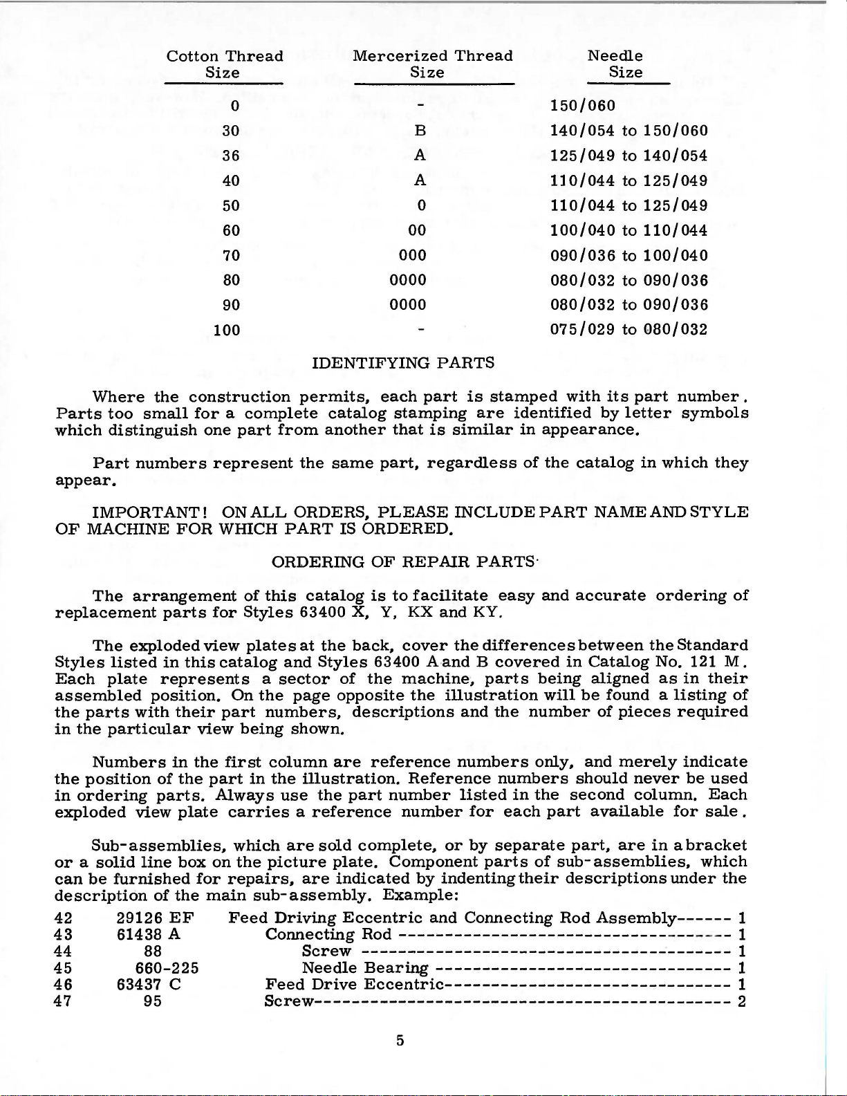
Cotton
Size
Thread
Mercerized
Size
Thread
Needle
Size
Where
Parts
which
Part
appear.
the
too
small
distinguish
numbers
0
30
36
40
50
60
70
80
90
100
construction
for a complete
one
part
from
represent
0000
0000
IDENTIFYING
permits,
catalog
another
the
same
each
stamping
that
part,
B
A
A
0
00
000
PARTS
part
is
regardless
is
stamped
are
similar
150/060
140/054
125/049
110/044
110/044
100/040
090/036
080/032
080/032
075/029
with
identified
in
appearance.
of
the
catalog
its
by
to
150/060
to
140/054
to
125/049
to
125/049
to
110/044
to
100/040
to
090/036
to
090/036
to
Q80/032
part
letter
in
number.
symbols
which
they
IMPORTANT!
OF
MACHINE
The
arrangement
replacement
The
exploded
Styles
Each
listed
plate
assembled
the
in
parts
the
with
particular
Numbers
the
position
in
ordering
exploded
view
Sub-assemblies,
or a solid
can
be
furnished
description
42
43
29126
61438 A
44
45
46
660-225
63437 C
47
FOR
parts
in
this
represents
position.
their
in
of
the
parts.
plate
line
box
of
the
EF
88
95
WIDCH
for
view
catalog
part
view
the
part
Always
on
for
main
ONALL
of
Styles
plates
On
being
first
in
carries
which
the
repairs,
Feed
ORDERS,
PART
IS
ORDERING
this
catalog
63400
at
and
a
sector
the
page
numbers,
X, Y, KX
the
back,
Styles
of
opposite
descriptions
shown.
column
the
use
are
picture
are
illustration.
the
part
a
reference
sold
plate.
are
indicated
sub-assembly.
Driving
Eccentric
Connecting
Screw
Needle
Feed
Drive
PLEASE
INCLUDEPART
ORDERED.
OF
REPAIR
is
to
facilitate
cover
63400 A-and B
the
machine,
the
reference
Reference
number
number
complete,
Component
by
PARTS·
easy
and
KY.
the
differences
covered
parts
illustration
and
the
numbers
numbers
listed
for
or
by
separate
parts
indenting
Example:
and
Connecting
Rod
-----------------------------
---------------------------------------Bearing
--------------------------------
Eccentric-------------------------------
Screw---------------------------------------------
number
in
each
their
and
accurate
between
in
being
will
be
only,
and
should
the
second
part
part,
of
sub-
descriptions
Rod
NAMEANDSTYLE
ordering
the
Standard
Catalog
aligned
No. 121
as
in
their
found a listing
of
pieces
merely
never
column.
available
are
assemblies,
required
indicate
be
used
Each
for
sale
in a bracket
which
under
the
Assembly------
---- - - - 1
of
M.
of
.
1
1
1
1
2
5
Page 6

In
catalog,
PC\,rts
in
for
the
Success
UNION
ration,
to
the
those
cases
no
specific
the.
v~rious
descr1pt1on,
in
the
SPECIAL
its
subsidiaries
most
approved
ORDERING
where a part
usage
ma?hines
and,
1f
necessary,
USE
GENUINE
operation
Needles
and
and
scientific
OF
will
be
are
of
Repair
authorized
principles,
REP
AIR
is
common
mentioned
not
the
the
d1fference
NEEDLES
these
machines
Parts
distributors.
PARTS
to
in
s.ame,
AND
as
furnished
and
(Continued)
all
of
the
description.
the
specific
w1ll
REPAIR
can
are
made
the
be
be
by
They
machines
usag~
shown
PARTS
secured
the
Union
are
with
utmost
covered
However,
will
~e
1n
the
lllustratlon.
only
with
Special
designed
precision.
by
this
when
men
the
ti~ned
genuine
Corpo-
according
Genuine
pair
parts
mark
is
are
your
Prices
are
forwarded
otherwise
directed.
CAUTION!
on
handwheel.
Before
carefully
packing
A
attaching
packed.
box,
bag
of
screw,
miscellaneous
The
bag
chronizer
lead
wire
bracket,
clamp
needles
are
stamped
guarantee
are
strictly
f. o.
b.
A
When
Using
leaving
both
factory,
After
the
following
PREPARATION
assembly
one
attachment
of
assembly
one
and
three
packaged
with
the
of
the
highest
net
cash
shipping
charge
is
unpacking,
hands
each
the
machine
steps
parts,
extra
bobbin,
to
the
parts
synchronizer
clamps
with
Union
Special
quality
TERMS
and
subject
point.
made
Parcel
to
INSTALLING
DO
NOT
on
bed
casting,
Union
Special
and
should
OF
be
MACHINE
consisting
two
bed
plate,
for
Styles
lead
for
tension
labels
marked~.
trademark,
in
materials
to
change
Post
cover
lift
the
machine
lift
machine
accessories
followed:
FOR
of
one
hinge
are
studs,
packed
63400
wire
clamp,
release
U S
and
without
notice.
shipments
postage
out
of
and
box
gently.
is
sewed
have
been
INSTALLATION
frame
KX
and
with
and
thread
KY
one
two
each
also
screw
solenoid
Genuine
Emblem.
Each
workmanship.
All
are
insured
insurance.
by
placing
off,
inspected
removed
eyelet,
screws
for
machine.
include
for
synchronizer
lead
wire.
re-
trade-
shipments
unless
one
hand
and
from
one
the
eyelet
holding
one
syn-
Insert
the
(4)
1.
2.
3.
4.
upper
For
steps:
Attach
(376
Attach
Slide
Attach
frame
Styles
A)
clamp
STANDARD
Included
ing
one
bobbin
its
clamp
and
screw,
essential
TABLE
spring,
when
TOPS
Lockstitch
the
bed
plate
hinge
the
studs
eyelet
63400
synchronizer
screws.
in
to
KX
The
synchronizer
(660-356)
clamp
to
synchronizer
ACCESSORIES
also
with
each
four
winder
isolator
setting
one
assembly,
knee
up
machines
is
FLUSH
with
holes
top
and
upper
to
adaptor
over
machine
lifter
pads
the
are
the
provided
of
arm
(A,
KY,
use
bracket
screw
of
synchronizer
bracket
is a box
the
machine
assembly
and
clips,
machine.
installed
top
of
for
them
Fig.
Fig.
(63495
also
2A).
lA
D)
to
handwheel
lead
using
of
mounting
and
its
and
one
in
table
the
machine
6
in
rear
as a guide
to
the
back
hold
clamp
assembly
wire.
(J87
J)
screw.
STANDARD
frame,
rubber
machine
tops,
pad,
rest
prepared
mounting
of
cloth
to
complete
of
plate.
machine,
(660-352)
using
the
two
ACCESSORIES-
one
oil
drain
bed
positioning
pin.
These
with
cut-out,
frame.
Assemble
the
following
using
in
position.
set
screws.
contain-
parts
jar
and
spring
are
so
that
two
Page 7
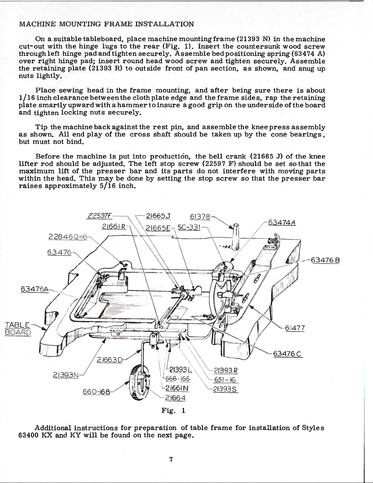
MACHINE
MOUNTING
FRAME
INSTALLATION
On a suitable
cut-out
through
over
the
nuts
with
left
right
retaining
lightly.
Place
1/16
inch
plate
and
smartly
tighten
Tip
as
shown.
but
must
Before
lifter
rod
maximum
within
raises
the
approximately
the
hinge
hinge
plate
sewing
clearance
upward
locking
the
machine
All
end
not
bind.
the
should
lift
of
head.
tableboard,
hinge
pad;
pad
lugs
and
insert
(21393
head
between
with a hammer
nuts
back
play
machine
be
adjusted.
the
presser
This
may
5/16
place
to
tighten
round
R)
to
in
the
the
securely.
against
of
the
is
put
The
be
done
inch.
the
rear
securely.
head
outside
frame
cloth
the
cross
into
left
bar
and
by
machine
mounting
(Fig.
Assemble
wood
front
mounting,
plate
to
edge
insure a good
rest
pin,
shaft
should
production,
stop
screw
its
parts
setting
1).
screw
of
pan
and
and
and
the
do
the
frame
Insert
bed
and
section,
after
the
frame
grip
assemble
be
taken
bell
(22597
not
stop
screw
(21393
the
countersunk
positioning
tighten
as
being
sides,
on
the
underside
the
knee
up
by
crank
F)
(21665
should
interfere
so
that
N)
in
spring
securely.
shown,
sure
there
rap
press
the
cone
J)
be
set
with
moving
the
the
machine
wood
(63474
Assemble
and
snug
is
the
retaining
of
the
assembly
bearings,
of
the
so
that
presser
screw
A)
up
about
board
knee
the
parts
bar
TABLE
BOARD
2284
6347
6Q-16
6
Fig.
1
-
63476C
Additional
63400
KX
and
instructions
KY
will
be
for
found
preparation
on
the
next
page.
7
of
table
frame
for
installation
of
Styles
Page 8
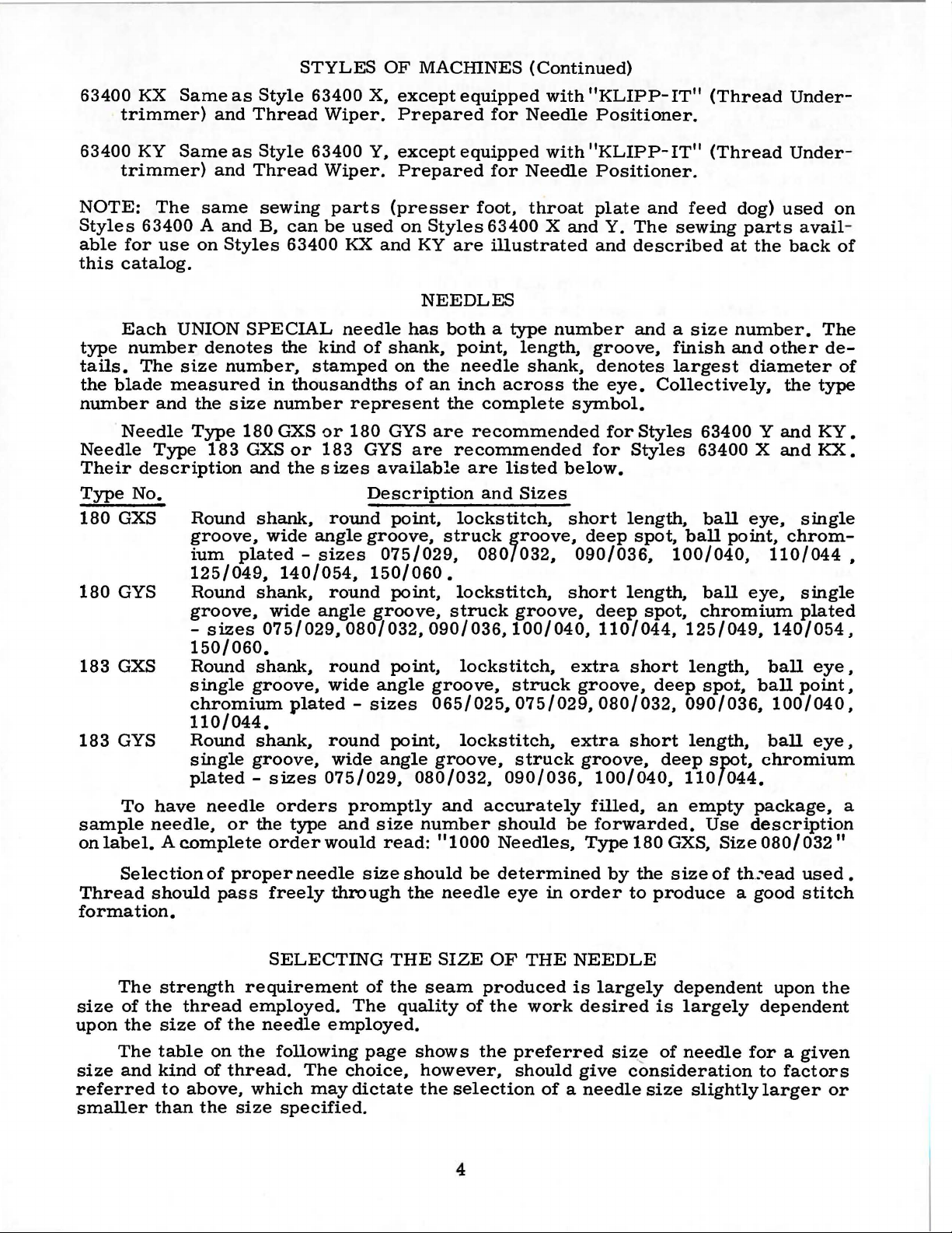
CLAMP
'-~-i
00
-
5YNCHR
ON
IZER
*c;;3"1-~5'D
6RAC.I<Er
*Jsu
SC
REW
2_
FRO
M TENSION-
J RELEASE
)_
FROM CUTTIN
J
SOLENOI
.SOLENO
D
*sc-a
92
SC
REW
}~~--:rl,
~=
't::,i.C-:t:J
ID
G.
-tr
,
..
(APPROX.)-----1
SCRcW.S
= = =
=::__
==
, ,
( DIA. DR
(BRACKET
EE
DETAIL
S
*
"SYNCHRONI
)
...
ILL
ZE.~
NU
TS
TO
SECUR£
BOX
UNDE
RTR
IMMER ELECTR
F
OR
63-400
IONS
ICATES
TilE
KN
362
EE
&.
ES
SHOWN
~BDIII
BUT
SWITCH
* INDICAT
DIMENS
NOT EQUIPPED WI
**IND
BOOXT-
1
if
63900
PA
SERIES MACHI
RT
INCLU
FOR DRIL
TH
STANCARD HOLES.
'PART INC
IS 0.
L..U0£0
·KN£
\IP.
ELIM
••
DIA.
ONI
C. EQUIPM
DED
E
SWITCHj
ILABLE (EXTRA
INATES
IN
PACKING.
LED
IN
29480
ENT
NE
HOLES ARE
WHICH
TREADU
PART
HP
5£ND
NE 5WI
NCI
S OX
IS
**TRIMM
NO
TE:
800XT-3~2
FOR
NOT
&.
CHARGE).
TC.I-I
£~
CI
BOARO WI
REMO
FROM
PRIIV
CIRCU IT
W
ITH
INSTALLATIONS
PART
RCU
TH
RELA
VE POWE.R PACI<
BOlt
AND
T~O
TR
IMH
BOARD
SCR£11$.
OF
Fig.
IT I I"=":
YS
I
NS~T
£R
(£SE
CURE
lA
aJ.IN
ECTEt
l
t-I
SIDE OF
SWITCH
80>
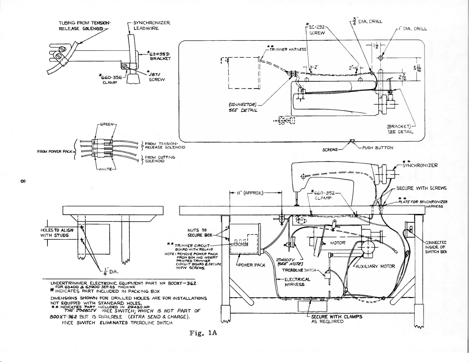
Page 9
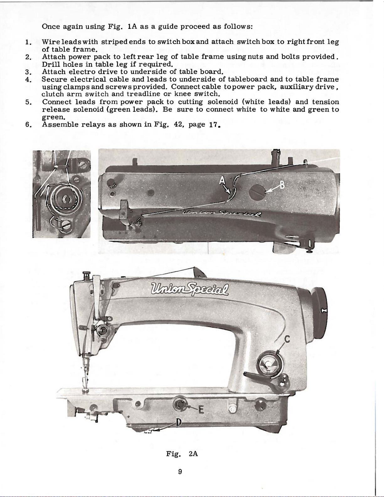
1.
2.
3.
4.
5.
6.
Once
Wire
of
Attach
Drill
Attach
Secure
using
clutch
Connect
release
green.
Assemble
again
leads
table
power
holes
electro
electrical
clamps
arm
using
with
frame.
pack
in
table
drive
and
switch
leads
solenoid
relays
Fig.
striped
to
leg
cable
screws
and
from
(green
as
1A
ends
left
rear
if
to
underside
and
provided.
treadline
power
leads).
shown
as a guide
to
switch
leg
required.
of
leads
pack
in
to
or
to
Be
Fig.
proceed
box
of
table
table
underside
Connect
knee
42,
switch.
cutting
sure
page
and
frame
board.
cable
solenoid
to
connect
17.
as
follows:
attach
using
of
tableboard
to
switch
nuts
power
(white
white
box
and
and
pack,
leads)
to
white
to
right
bolts
to
table
auxiliary
and
and
front
provided.
green
leg
frame
drive,
tension
to
Fig.
2A
9
Page 10
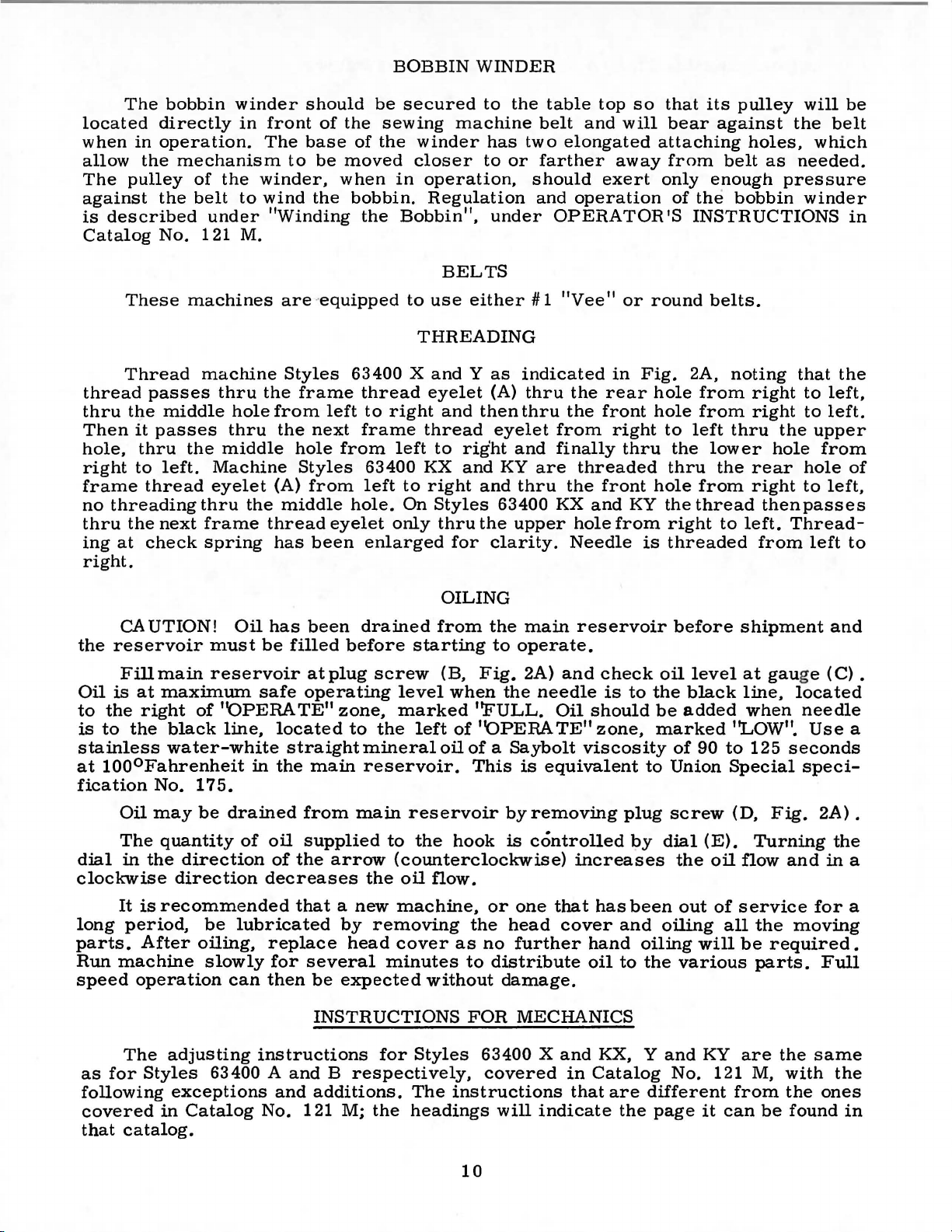
The
located
when
in
allow
The
pulley
against
is
described
Catalog
bobbin
directly
operation.
the
mechanism
of
the
belt
No.
winder
in
the
to
under
121 M.
should
front
The
to
of
base
be
winder,
wind
the
"Winding
be
the
sewing
of
the
moved
when
bobbin.
the
BOBBIN
secured
machine
winder
closer
in
operation,
Regulation
Bobbin",
BELTS
WINDER
to
the
belt
has
two
to
or
farther
should
and
under
table
top
and
so
will
elongated
away
exert
operation
OPERATOR'S
that
its
pulley
bear
attaching
from
only
of
against
belt
enough
the
holes,
bobbin
INSTRUCTIONS
will
the
as
needed.
pressure
winder
be
belt
which
in
These
Thread
thread
thru
Then
hole,
right
frame
no
thru
ing
passes
the
middle
it
passes
thru
to
left.
thread
threading
the
next
at
check
right.
CAUTION!
the
reservoir
Fillmain
Oil
is
at
maximum
to
the
right
is
to
the
black
stainless
at
1000Fahrenheit
fication
water-white
No.
machines
machine
thru
hole
thru
the
middle
Machine
eyelet
thru
the
frame
spring
Oil
must
reservoir
of
''OPERATE"
line,
in
175.
are 'equipped
Styles
the
frame
from
the
left
next
hole
Styles
(A)
from
middle
thread
has
has
be
eyelet
been
been
filled
atplug
safe
operating
zone,
located
straight
the
main
to
use
either# 1 "Vee"
THREADING
63400 X and Y as
thread
to
frame
from
63400
left
hole.
enlarged
right
left
to
On
only
eyelet
and
thread
to
right
KX
and
right
Styles
thru
for
then
and
the
OILING
drained
before
screw
to
the
mineral
reservoir.
from
starting
(B,
level
when
marked
left
oil
Fig.
't.FULL.
of
''OPERATE"
of a Saybolt
This
indicated
(A)
thru
thru
eyelet
and
KY
are
thru
63400
upper
clarity.
the
main
to
operate.
2A)
the
needle
is
in
the
rear
the
front
from
right
finally
threaded
the
front
KX
and
hole
from
Needle
reservoir
and
check
is
Oil
should
zone,
viscosity
equivalent
or
Fig.
thru
KY
is
to
to
round
2A,
hole
hole
to
left
the
thru
hole
the
thread
right
threaded
before
oil
level
the
black
be
added
marked
of
90
Union
belts.
noting
from
from
thru
lower
the
from
to
to
Special
right
right
the
hole
rear
right
then
left.
Thread-
from
shipment
at
gau
line,
when
"LOW".
125
seconds
that
the
to
left,
to
left.
upper
from
hole
to
left,
passes
left
and
ge
(C).
located
needle
Use
speci-
of
to
a
Oil
may
be
The
dial
in
the
clockwise
It
is
long
parts.
Run
speed
period,
After
machine
operation
The
as
for
Styles
following
covered
that
catalog.
drained
quantity
of
direction
direction
recommended
be
lubricated
oiling,
slowly
can
adjusting
63400 A
exceptions
in
Catalog
from
oil
supplied
of
the
decreases
main
arrow
the
that a new
by
removing
replace
for
then
head
several
be
expected
INSTRUCTIONS
instructions
for
and B respectively,
and
additions.
No. 121 M;
the
reservoir
to
the
hook
by
is
(counterclockwise)
oil
flow.
machine,
cover
minutes
without
Styles
or
one
the
head
as
no
further
to
distribute
damage.
FOR
MECHANICS
63400 X and
covered
The
instructions
headings
will
removing
controlled
that
cover
indicate
10
plug
increases
has
and
hand
oil
to
KX,
in
Catalog
that
are
the
screw
by
dial
been
oiling
oiling
the
Y
and
No.
different
page
(E).
the
oil
out
of
all
will
various
KY
121 M,
it
can
(D,
Fig.
Turning
flow
service
the
be
required.
parts.
are
from
be
and
for
moving
the
same
with
the
found
2A).
the
in
Full
the
ones
in
a
a
Page 11

CHANGING
To
change th
locknut
(B).
stitch
turning
locknut
NOTE:
(A,
Turning
length
the
(A)
Mter
feed
dog
verse
THE STITCH
e l e
Fig.
28)
and
the
screw
resulting
screw
after
feed
to
obtaining
setting
has
equal
direction.
the
the
LENGTH
ngth
of
turn
to
in
more
left
acts
the
stitch
clearance
stil.ch,
the
the
desired
(Page
feed
right
stitches
the
reverse.
length
at
12)
loosen
adjusting
decreases
per
stitch
make
the
front
knurled
screw
inch
and
Tighten
length.
sure
and
the
the
back
in
both
Fig.
the
28
forward
and
re-
NOTE:
lever
control
Set
feed.
stitches
both
inch
the
"Changing
This
mechanisms.
in
both
other.
The
(C,
the
can
per
To
The
SETTING
reverse
Fig.
lever
stitch
inch
directions,
28)
is
length
be
checked
on
After
change
Stitch
feed
is
and
held
down.
at
using
the
forward
making
because
the
Length".
THE
actuated
the
12
stitch
REVERSE
reverse
stitches
heavy
and
an
adjustment
an
adjustment
length
adjusting
This
back
(B).
control
verse
the
ing
both
by
pushing
feed
per
inch,
paper
reverse
of
the
The
reverse
the
can
be
against
When
travel.
an
directions.
the
lever
feed
adjustment
FEED
will
or
feed,
accomplished
the
travel
Retighten
MECHANISM
down
continue
on
both
very
it
to
one
to
one
forward
feed
stitch
rest
machine
(A)
toward
or
and
light
pin
on
the
to
the
may
feed,
feed
feed
travel
control
and
is
in
you
away
clamp
check
reverse
operate
forward
cardboard.
require
check
will
affect
refer
lever
by
tipping
loosening
thispositionmove
to
from
screw
the
as
adjustments
the
to
paragraph
can
be
(A,
increase
you
(B)
stitch
the
clamp
feed
and
To
stitches
the
to
control
long
reverse
attain
travel
changed
Fig.
machine
the
decrease
after
length
as
the
12
per
on
by
29) .
screw
the
re-
mak-
in
of
of
can
made
the
factory
not
to
be
obtained
the
Fig.
feed
and
29
by
linkage
may
adjusting
located
be
checked
NOTE:
CAUTION:
the
stitch
inside
as
outlined
Once
been
stitch
"Changing
feed
get
in
control
move
against
If
set
length
will
approximately
both
directions.
On
this
the
equal
length
the
machine.
on
the
11
the
at
12
can
The
not
have
machines
reverse
lever
rest
stitch
control
next
forward
stitches
The
be
made
Stitch
to
be
the
feed
before
pin.
length,
lever,
feed
page.
and
reverse
per
inch, a change
as
Length",
adjusted,
same
equipped
number
lever
tipping
forward
adjustment
linkage
feed
described
the
reverse
you
of stitches
with a treadle
(A,
Fig.
machine
and
reverse
should
is
pre-
has
under
should
30)
re-
back
set
in
be
at
Page 12

SETTING
THE
REVERSE
FEED
MECHANISM
(Continued)
verse
and
screw
adjusting
NOTE:
feed
adjust
(B)
APPLY
lever
the
in
screw,
THE
Fig.
TO
30
(A,
Fig.
stop
this
REMAINDER
screw
position
when
MACHINE
reverse
30),
hold
(B,
Fig.
with
OF
THE
STYLES
Drain
remove
cover.
stitches
ing
screw
the
stitch
ver
(B),
(C)
is
bottom
holding
the
bottom
Now
to
ver
locknut
feed
adjustment
the
as
On
down
30)
is
actuated
ADJUSTINGINSTRUCTIONS
63400
PRESSER
machine
the
bottom
Set
the
per
inch.
(A,
regulator
so
the
23/32
of
the
screw
reservoir
reverse
described
machines
the
reverse
to
stop
(C).
This
KX
AND
machine
Loosen
Fig.
31)
center
inch
base.
(A)
can
feed
earlier.
equipped
against
is
by
stepping
KY
BAR
plunger
and
control
feed
to
of
oil
and
reservoir
at
zero
hold-
and
move
le-
of
screw
above
Retighten
be
prevent
ONLY.
CONNECTION
the
replace
cover.
made
le-
with a treadle
control
the
bed
casting.
damage
on
the
IN
Fig.
lever
treadle.
THIS
(Page
31
control
(C,
Fig.
Lock
to
CATALOG
the
15)
stop
feed
re-
28)
When
directly
is
set
properly
connection
To
obtain
loosen
Set
needle
pressure
direction.
the
set
guide
enters
locating
against
(A,
screw
to
to
the
Fig.
the
when
Fig.
this
(D).
the
the
presser
12A
the
presser
throat
there
16A).
setting,
Tap
1/16
middle
plate
is a 1/16
remove
on
presser
inch
of
its
foot
by
should
the
This
back
nut
(B)
ing
setting
complished.
stop
bar
guide
with
the
inch
the
foot
dimension,
slot
and
turning
The
be
lower
is
against
(A,
Fig.
on
the
the
stop
of
screw
PRESSER
(B,
Fig.
feed
space
pressure
to
insure
center
retighten
the
presser
presser
set
presser
accomplished
lifter
screw
the
in
dog
between
the
bar
so
that
the
rest
15)
and
lever
to
presser
Tighten
place.
BAR
16A),
in
its
from
its
the
being
foot
screw
spring
the
the
lowest
connection
it
is
about
bar
bushing
by
tipping
pin,
relocating
bell
crank
right
bar
the
lock
GUIDE
presser
position.
guide
(B)
presser
down
by
turning
(D)
in
regulator
(A,
7/16
(Fig.
the
loosening
the
(C).
or
left,
connection
nut
(A)
(Page
foot
and
presser
spring
on
the
throat
it
so
guide.
Now,
in a clockwise
Fig.
inch
machine
the
stop
By
the
proper
to
lock
16)
must
The
(C)
that
16A)
above
16A).
lock
screw
turn-
is
ac-
the
rest
guide
bar
and
plate.
the
apply
Set
the
wire
is 4 3/4
needle
inches
thread
above
take-
the
up
wire
throat
(A,
plate.
12
Fig.
16B)
so
that
the
underside
of
the
Page 13

out
Fig.
thread
16A
in
the
TENSION
1.
2.
3.
tension
RELEASE
Set
the
tension
that
centered
eyelet
Solenoid
16A)
lease
noid
trude a minimum
to a maximum
If
move
in
screw
arm
(B,
Tension
(F,
plunger
clearance
the
(A,
must
pin
plunger
adjustment
tension
or
out
located
and
Fig.
Fig.
disc.
tension
on
the
Fig.
plunger
touch
and
the
pin
post
by
moving
18A)
release
16A)
pin
(E)
between
(Page 1 7)
assembly
discs
check
18A)
pin
(E.
tension
end
of
must
of
1/3 2 inch
of
1/16
is
required
assembly
loosening
under
with
stop
as
required.
solenoid
is
it
machine
a
to
ar
spring
Fig.
re-
sole-
pro-
inch.
set
screw
set
have
and
the
so
e
is
secured
screw
in
approximately
tension
Fig.
to
flat
bracket.
release
16B
of
bushin
Solenoid
.
005
pin
4-
inch
with
3"
4
g
-
4.
This
solenoid
noid
should
plunger
the
tension
The
manual
release
The
raising
point
screw
NOTE:
as
is
of
Check
Fig.
the
can
be
plunger
then
pin.
Care
disc.
tension
thread
tension
or
lowering
between
securely.
Head
the
18A
case
oiler
slot
the
may
accomplished
pin
and
be
slipped
should
After
tension
release
1/
4to
in
the
oil
gauge
TRIMMER
ger
chine
1.
There
shake
carrier
adjustment
loosening
pivot
taking
be.
tightening
release
when
to
suit
5/16
bracket
connecting
Remove
and
knife
and
the
end
onto
be
taken
cam
the
cam
can
the
inch
must
to
be
ADJUSTMENTS
the
assembly
proceed
should
in
lower
(A,
screw
release
up
the
by
placing
of
tension
bushing
not
to
set
(G,
presser
be
positioned
sewing
of
presser
locate
rod.
The
sure
can
it
reads
positioning
as
follows:
be
no
knife
Fig.
be
(B)
lever
excessive
a .
005
release
and
moved
exert
screw
Fig.
conditions.
the
from
bind
32).
made
(C)
16A)
foot
foot
needle
wick
full
fin-
ma-
pivot
This
on
and
too
remove
by
the
end
is
by
lift
must
or
inch
spacer
pin.
in
until
much
spacer.
should
raised
loosening
The
above
bar
contact
and
operates
play
The
tension
it
contacts
pressure
be
set
for
back
average
the
throat
link
oil
the
or
relieving
between
release
thereby
so
that
tacking.
screw
tension
plate.
wick
in
needle
freely.
Fig.
32
the
head
the
solenoid
opening
it
will not
(H)
and
release
Tighten
the
bearings
the
of
sole-
then
center
.
bind
13
Page 14

THIMMER
ADJUSTMENTS
(Continued)
Fig.
33
adjustment
The
beyond
moves
of
loosen
the
to
the
positioning
screws
or
lower
left
the
Position
the
tioning
lower
knife.
finger
centric
are
would
eccentric
mately
arm
Adjust
adjust
to
CAUTION:
parallel
knife
side
right.
(A.
left
parallel.
of
lower
(A.
of
the
finger
Fig.
upper
side
finger.
knife
set
If
is
this
screw
bushing
be
to
have
bushing
90°
to
the
positioning
lower
the
lower
knife
Be
adjustment
Fig.
the
33)
arm
run out
as
indicated
34)
and
knife
of
the
Check
parallel
is
not
(E)
(F)
A
good
the
(F)
the
knife
knife
and
counterclockwise
sure
will
in
its
of
the
of
the
position
(D)
parallel
arm
to
with
so.
and
until
of
the
see
the
loosen
turn
the
starting
pin
hole
located
right
finger
until
turn
side
(Fig.
it
just
flange
approxi-
bushing
have
to
extreme
positioning
cutting
at
point
edge
(D).
knife.
posi-
that
upper
the
knives
point
in
of
contacts
screw
is
not
be
checked.
left
finger
with
the
the
ec-
the
the
34) .
to
turned
position
(C)
must
To
make
(G.
raise
(B).
Fig.
the
upper
Fig.
it.
while
should
As
the
coincide
these
34
knife.
32)
clockwise
making
not
extend
lower
at a point
adjustments
To
this
knife
4.
5.
Locate
far
forward
of
feed.
tacting
the
pivot
inch
clearance
spring
Adjust
when
the
position.
with
the
case
holder.
the
With
the
release
(A.
the
lower
the
left
Fig.
cutting
as
possible
the
cutting
to
Fig.
lower
knife
left
side
35
solenoid
cutting
solenoid
lever
be
maintained
36)
is
knife
corner
of
the
is
(D),
in
stop
in
bracket
and
parallel
solenoid
plunger
so
position.
screw
its
(E.
needle
Assemble
3.
assembly
case
assembly
until
the
ing
cess
assembly
ing
edge
bobbin
(A.
lever
that
there
when
(B.
extreme
Fig.
slot
33)
in
holder
the
projection
finger
(B)
1/32
of
Fig. 3 5)
with
the
(B)
(C).
is a 1/32
knife
return
Fig. 3 6)
right
is
in
the
bobbin
positioning
into
by
finger
into
and
attaching
inch
projection
case
recess
as
line
con-
adjust
so
hand
line
machine.
positioning
turning
the
recess
(A.
Fig.
the
bobbin
tighten
screws
clearance
and
(Fig.
finger
Adjust
finger
bobbin
is
at
12A)
the
finger
between
the
12A).
Fig.
and
the
and
case
the
top.
on
the
case
holder
and
securely.
the
inside
36
knife
bobbin
knife
holder
Place:
position-
re-
knife
allow-
outside
edge
of
CAUTION:
making
Be
this
adjustment.
sure
cutting
Also
solenoid
be
sure
lever
knife
contacts
does
14
not
the
hit
lower
the
hook
knife
point.
stop
when
Page 15

TRIMMER
6.
Be
when
not
sure
the
make
ADJUSTMENTS
the
spring
lower
contact,
retainer
knife
bend
is
in
its
retainer
(Continued)
wire
extreme
(B,
right
wire
Fig.
to
34)
hand
suit.
contacts
position.
the
If
bobbin
the
spring
case
hold
wire does
er
NOTE:
7.
from
Knife
machine
return
tension
(D)
to
the
SYNCHRONIZER
(a)
Rotate
the
plate
assembly
stroke
(b)
At
band
front
this
flectorplate
set
required.
(c)
The
at
rotate
loosen
rotate
the
If
positioning
spring
of
knife
right
handwheel
needle
(C,
of
this
time
(A,
edge
adjustment
screws
needle
bottom
handwheel
screw
third
middle
or
position
(A,
r e
turn
to
increase
ADJUST
clearance
Fig.
is
in
line
the
needle
the
Fig.
of
3 7)
the
position
as
described
(C)
in
positioner
of
stroke.
(D)
band
of
the
finger
assembly
changed,
Fig.
36)
spring
loosen
tension
lVIENT
in
operating
cut
12A)
on
with
the
the
bar.
brass
contact
should
brush
holder
needle
above,
synchronizer
should
If
not,
until
at
from
black
end
it
is
of
left
plastic
or
check
to
have
proper
screw
or
to
the
direction
in
the
deflector
rotating
needle
be
flush
(B).
bar
on
of
the
with
To
and
then
and
move
position
with
power
at
bottom.
synchronizer
(E)
in
operating
band.
cutting
step
(C)
left
until
hook
the
up
left
the
make
de-
loosen
as
needle
off
Then
and
solenoid
5.
tension
and
move
to
decrease
direction
to
cut
tension
bracket
threads.
the
Fig.
until
are
To
spring
tension.
37
its
brush
removed
adjust
bracket
is
in
(d)
The
needle
Fig.
38
needle
or
If
in
top
end
band
the
Turn
positions
CLUTCH
1.
Set
2.
Adjust
so
nut
inch
thread
1/8
inch
not,
with
operating
of
its
of
synchronizer
from
middle
on
power
ARM
needle
clutch
that
treadle
washer
from
stroke.
of
end
15
positioner should
take-up
from
power
direction
the
top
off
Then
at
top
of
rotate
until
loosen
and
left
(F)
of
the
and
the
SWITCH
in
work.
arm
will
(B)
is
of
until
black
check
needle
spring
retur.n
to
be
stud).
its
the
bar.
ADJUSTMENT
approximately
position
of
its
strok
its
up
stroke.
handwheel
it
is
at
the
screw
rotate
brush
plastic
up
and
at
fourth
is
in
band
down
I
(A, Fig. 38)
to
stop
(win
1/2
e
.
g
Page 16

CLUTCH
3.
Close
switch
it
needle
this
and
setting.
ARM
treadline
screw
the
micro
positions
SWITCH
switch
(C).
until
switch.
up.
ADJUSTMENT
and
loosen
there
Tighten
is
Then
no
tighten
nut
(Continued)
clutch
contact
screw
(D)
to
lever
between
until
maintain
CAUTION!
lever
ning;
engaged.
THREAD
1.
Rotate
adjust
hook
is
catches
at
the
Fig.
switch
one
click
WIPER
thread
thread
top
39
Clutch
is
wiper
wiper
the
of
its
~..,...--
8
3 1.
2.
must
closed
must
not
or
auxiliary
be
heard
ADJUSTMENTS
mounting
guide
needle
(63470
thread
stroke.
ADJUSTING
Depress
indicates
Adjust
1/16
Loosen
Lock
treadle
switch
clutch
to
1/8
lock
Motor)
approximately
the
top
on
the
engages
engage
as
described
when
motor
before
collar
P),
when
(63470
so
the
CLUTCH
unit
is
so
that
inch
travel
screw
just
one
turn.
right
clutch
is
run-
clutch
t~at
H)
is
and
the
take-up
until
open.
clutch
before
(E.
enough
end
above.
one
arm
Fig.
to
Adjust
of
the
Tighten
click
has
clutch
38)
unlock
screw
motor
is
heard,
which
approximately
is
engaged.
(where
it.
it
which
located
until
lock
clutch
screw
says
is
near
(E).
2.
Thread
3.
snap
Form
ment
when
in
CAUTION!
solenoid
wiper
against
when
failure
to
return
INSTALLATION
When
be
sure
located
before
not
function
Should
later
date.
replaced
position
wiper
lever
(63470
released.
thread
thread
guide
plastic
adjusting
of
wiper
Thread
from
(63470
solenoid
wire
wiper
guide
wiper
returning
P)
tube.
Be
thread
will
completely.
OF
INCffiNG
installinginchingswitch.
to
remove
between
connecting
pin
the
#2
inching
properly.
the
inching
the
jumper
or
the
needle
up.
E)
(63470
(63470
hook
to
its
so
that
sure
wiper
result
jumper
and
pin
switch
switch
wire
(A,
positioning
must
F)
for
P).
must
stop.
hook
to
does
loosen
lever.
if
it
is
SWITCH
(No.
wire
#3
plug
be
removed
Fig.
return
free
not
Move
not
set
Premature
not
670
(A.
Fig.
on
socket
or
39)
must
unit
will
with
move-
prevent
thread
stop
screws
allowed
B-21)
39)
(B)
it
will
at
be
not
a
a
Fig.
40
16
Page 17

If
pressed,
treadle
out
trimming.
needle
the
pushbutton,
the
is
heeled
out
of
cutter
while
This
the
work,
which
band
the
enables
but
PUSHBUTTON
is
mounted
of
the
synchronizer
pushbutton
the
operator
without
having
on
is
depressed.
to
trimmed
FUNCTION
the
front
is
interrupted.
the
readjust
or
the
edge
needle
realign
threads.
of
the
table
Th~refore,
will
the
board,
position
garment
is
when
up
with-
with
de-
the
the
To
screws
moved
length.
If
more
can
be
compressed
ion
bushing
If
more
bushings,
should
The
switch
(E).
be
roller
actuator
adjust
in
and
the
the
(C)
or
the
back
less
up
travel
micro-switch
taken
on
the
bushing
length
three
more
or
is
so
that
switch
TREA
of
panel.
bushings
pressure
or
down.
required
actuator
only
should
(D).
DLINE
the
If
more
is
less
in
enough
This
SWITCH
pitman
adjustment
inside
the
required
accordingly
the
treadle
(D)
and
travel
not
be
allowed
is
accomplished
rod
switch
when
stop
is
ADJUSTING
(A,
Fig.
40)
is
necessary
relocated
heeling
by
moving
for
actuating
bushing
provided
to
to
ride
by
adjustment
loosen
the
the
(E).
actuate
over
the
to
obtain
treadle,
pitman
the
trim
must
the
bevel
of
the
two
cover
must
the
the
rod
spring
cycle,
be
lowered.
the
micro-switch.
on
the
the
stop
Allen
be
desired
spring
the
micro-
bushing
set
re-
(B)
tens-
two
Care
The
power
circuitbreaker.
fuses
AMP
the
located
and
the
slow
primary
under
relay
auxiliary
blow
coil
Fig.
winding
41
pack
The
fuse
the
chassis,
control
FUSING
incorporates
11/2
motor
(A,
of
AMPcircuit
as
Fig.
the
transformer.
for
circuit
well
42)
the
(24
THE
a
safety
as
the
located
thread
VDC).
POWER
feature
breaker(A.
positioner
on
top
of
The 5 AMP
wiper
17
PACK
consisting
Fig.
the
solenoid
41)located
circuit
chassis
straight
(30 VDC),
~
Fig.
42
of
two (2)
inthe
components.
fuses
blow
the
fuse
cutter
fuses
frontpanel
The 1 1/4
AC
input
(B.
Fig.
solenoid
and
for
41)
a
Page 18

1.
2.
3.
4.
5.
6.
7.
8.
9.
10.
1.
FOR
Unit
Unit
Unit
Unit
Unit
Auxiliary
Unit
Auxiliary
Unit
Auxiliary
Check
does
positions
trips
trips
keeps
positions
trips
FOR
the
TYPICAL
UNITS
not
position.
up
in
circuit
the
on
motor
motor
circuit
motor
UNITS
following:
breaker.
circuit
stitching
runs
slowly.
runs
breaker
will
TYPICAL
WITH
second
breaker
at
while
very
not
WITH
NEEDLE
PRINTED
position.
every
an
inching
clutch
hot.
after
turn
NEEDLE
PRINTED
positioning
over
POSITIONER
CIRCUIT
but
does
few
hours
speed.
is
engaged
one
although
POSITIONER
CIRCUIT
you
PROBLEMS
BOARD
not
position
or
every
with
BOARD
rna
time.
know
SOLUTIONS
CONSTRUCTION
down.
few
days.
in
motor.
power
CONSTRUCTION
is
feeding
it.
Circuit
Synchronizer
Treadle
Input
Auxiliary
Loose
PrintedCircuitBoard(Check
nal
2.
The
the
3.
SCR
4.
Check
Grounded
Oil
Field
Operator
5.
Check
breaker
jack
power
motor
connection
End).
treadle
power
is
saturated
is
shorted.
the
following:
armature
deteriorated.
fluttering
the
following:
jack
switch
turned
armature.
and
brushes
(check
is
not
off
Replace
(tie
Replace.
treadle
brushes
and
soldered
opening.
and
then
board.
bolt
excessively.
armature
connections)
forlooseconnection
The
unit
will
back
touching
on
again.
field).
or
oxidation
position
down
on
the
Plug
first
in
Termi-
time
after
Synchronizer
Brush
Damaged
Synchronizer
Very
Defective
location
loose
field
V-belt.
brake
male
loose
and
on
synchronizer.
coil
in
on
SCR
female
au:x:iliary
handwheel.
circuit.
jacks.
motor.
Replace
Clean
printed
18
synchronizer.
circuit
board.
Page 19

6.
Treadle
7.
Armature
ture
8.
Check
switch
has
dressing
the
following:
is
not
poor
stone).
opening,
commutation
or
is
defective.
or
is
partially
shorted
and
dirty.
(Use
arma-
Setting
Opera
Grounded
Brake
No.
Check
two
position
of
the
9.
Check
Lead
Brush
10.
Check
Armature
The
of
treadle switch.
tor
fluttering
field
gear
9855.
operation.
units,
operation.
the
following:
rubbing
holder
the
following:
Chassis
coil
seized
Sometimes
thereby
This
in
armature.
jammed
brushes
is
Equipped
the
(tie
on
will
and
treadle.
bolt),
hub.
it
using
Replace
is
the
greatly
against
brush
armature.
holder.
Voltage
With A Dual
or
defective
possible
positioner
prolong
field
with
new
to
remove
to
life
and
Adjustment
Value
Power
coil.
gear
and
the
only
raise
minimize
Resistor
Replace
brake
down
the
maintenance.
(See
field.
assembly,
position
Needle
Figure
brush
at
the
Part
on
end
43).
As
Figure
portion
portion
is
is
43
to
be
used
shows
used
when
the
when
the
75
50
Ohm
resistor
the
supply
Ohm
over
220
has a value
line
voltage
voltage
Volt
Fig.
220
and
is
Volt
43
is
220
above
of
50
volts
220
ohm
or
volts.
and
75
lower,
ohm.
second
The
the
50
75
ohm
ohm
19
Page 20

Before
bility
at
for
suggestions
this
all
machine
times.
which
left
If,
however,
may
the
prove
factory,
the
beneficial
it
was
trimmer
adjusted
has
been
to
you,
and
inspected
readjusted
and
so
is
as
not
to
give
trimming
the
utmost
properly,
satisfaction
see
the
and
chart
dura-
be low
Both
Needle
thread
Bobbin
thread
Lower
the
way
threads
thread
cut
thread
cut
knife
Condition
not
cut
not
cut,
not
cut,
does
not
but
bobbin
but needle
return
all
TRIMMER
Solenoid
Lower
enough
Lower
wipes
Lower
slip
Spring
ing
catching
Lower
enough
Hook
Bobbin
in
Needle
big
Not
return
and
more
spring
threads
knife
off
retainer
bobbin
knife
No,
thread
bobbin
hole
or
has
enough
sprin
rou
tension
knife
to
knife
when
to
gh
TROUBLESHOOTING
Causes
not
working
moving
not
the
right
far
too
behind
too
knife
case
position
does
right
29474 R
not
case
in
throatplate
been
tension
g.
thread
far
wire
altered
Dense
on
forward,
knife
back,
returns
not
holder
not
move
or S used
threaded
on
lower
material
will
knife
threads
contact-
when
is
knife
require
return
far
in
far
thru
too
Check
lead
Make
continuity
Reset
stop
Relocate
on
radius
Relocate
Bend
spring
Adjust
setting.
noid,
Operate
off,
to
determine
lever
is
and
then
necessary
Use
only
Thread
Use
throat
needle
return
to
Increase
the
right
hole,
spring
Cures
connections
check
screw
knife.
Check
knife
retainer
stop
screw
Check
position
machine
contacting
No. 29474 T
properly
tension
if
reposition
plate
if
available
on
by
moving
for
wire
to
standard
of
with
solenoid
stop
solenoid
hook
with
smaller
lower
bracket
nicks
to
suit.
sole-
belt
pivot
screw
knife
if
Needle
random
Needle
Bobbin
NOTE:
thread
unthreads
thread
Refer
information
tears
lengths
breaks
to
of
starting
when
Amco
regarding
and
starting
or
leaves
tail
Quick
Catalogs
the
needle
Lower
Too
tensio
.
needle
thread
Tension
Needle
tioned
Needle
big
Bobbin
Overspin
Too
tension
Sharp edg
knife,
edges
knife)
furnished
positioner
knife
much
.n
pull-off
thread
properly
hole
thread
much
(Front
are
rubbing hook
knife
and
excessive
thread
disc
not
in
on
bobbin
knife
es
o.n
,
the
with
and
return
friction
eyelets
at
cone
open
take-up
at
top
throat
plate
too
short
thread
return
T.
C.
S.
point
T.
C.
S,
each
needle
electrical
point
spring
and
not
of
stroke
is
spring
of
lower
and
of
lower
circuitry.
in
in
posi-
too
back
positioner
Check
bobbin
Decrease
spring sli
et
Stone
lower
back
lower
for
Raise
lower
Unthread
the
right
crease
spring
pull-off
Check
setting
solenoid
tion
of
Check
take-up.
of
the
top
Use
throat
needle
See
bobbin
wind
to
the
sharp edg
knife.
edges
knife)
guardian
knife
some
of
tension
on
of
tension
electrical
of
be
within
its
upstroke
plate
if
available
breaks
of
bobbin
case
on
by
moving brack-
es
(Front,
are
the
the
knife
needle
with
knife
ofT.
of
the
tension
slightly. Check
at
cones
and
this
solenoid
position
Must
of
hole,
thread
in
bobbin
tension
ghtly,
left
maintenance
eyelets
post.
release
1/8
smaller
and
holder
C.
point
T.
C.
and
Dereturn
thread
opera-
thread
inch
fit
return
S.
and
S.
other
to
of
of
of
20
Page 21

EXPLODED
AND
VIEWS
DESCRIPTION
STYLES
PECULIAR
63400
X,
OF
Y ,
PARTS
TO
KX
and
KY
21
Page 22

--1
, I
)
I
I
I
22
Page 23

ROTATING
HANDWHEEL
FOR
HOOK
MACHINE
ASSEMBLY,
ASSEMBLY
STYLES
NEEDLE
AND
63400
POSITIONER
MISCELLANEOUS
KX
AND
KY
ASSE
PARTS
ONLY
MBLY
,
t -
*
Ref.
No.
1
2
3
4
5
6
7
8
9
10
11
13
15
16
17
19
20
21
22
23
24
25
26
27
28
29
30
31
32
33
34
35
36
37
38
39
40
41
42
43
44
45
46
47
48
49
50
51
52
53
54
55
56
57
58
Part
No.
29474
63913
63913
63913
61414 c
22716
22564
61216
61216
61415
61415
61212
63414
22716
63410
22569
63408
22716
61411 A
63421 A
61321 L
22574
61421
660-254
61421 E
63421
22894
J87
660-356
63495
376
660-352
63459
73
22570
63492
63492
63458 B
660-219
22513
63458
63432
18-768
22894
63439
A
63439
63982
22571 G
22841 K
41071
HS82
22766
63970
A
800
XT-362
T
A
B
B
E
N
A
A
H
H
c
BC
c
v
J
D
A
A
c
E
D
D
E
J
B
c
G
Description
Rotating
Handwheel
D
Screw,
Synchronizer
Synchronizer
Screw,
Tension
Presser
Bushing,
Tension
Tension
B
Screw-----------------------------------------------------Tension
Feed Dog
Throat
Oil
Drive
Screw,
Feed
Feed
Oil
Plug
Stud
Presser
Nut
Screw------------------------------------------------------
Screw-----------------------------------------------------Needle
Needle Pos
synchronizer
Hook
Bobb
Bobbin
Bobbin
Bobbin
Screw-------------------------------------------------Hook
Screw-----------------Hook--------------Screw--------Hook
Retainer
Screw--------------------------------------------------
Handwheel---------------------------------------------Isolator
Handwheel
Pulley--------------------------------------------------
for
for
Set
Screw-----------------------------------------------
Screw--------------------------------------------------
Roll
Plate
Shield---------------------------------------------------
Screw
for
Dog
Dog
Reservoir
Screw,
Screw,
--------------------------------------------------------
Thread
Assembly--------------------------------------
in
Case
Assembly-----------------------------------
Case
Assembly-
Bobbin
Bobbin
Tension
Screw---------
Bobbin
Bobbin
Bobbin
Bobbin
Thread
Thread
Set
Release
Bar
for
Release
Release
Pin------------------------------------------------
Release
(See
Holder
Holder
Foot
Case
-------
Case
Tens
Regulating Screw----------------------------
Case
Latch
Case
Latch
Case
Latch
Case
Latch
----------Case
Holder--
Deflector-----------------------------------
- - - -
Assembly-----------------------------------------
synchronizer
synchronizer
feed
itioner Ass
Retainer------------------------------------
Plate
------------------------------------------
Washer-----------------------------------
Isolator
Screw-------------------------------------------
Lead
Wire
Bracket----------------------------------------
Solenoid
Guide
tension
(See Page 29)
------------------------------------------------
for
for
------------------------------------------
release
Plunger
Bushing and
Cam----------------------------------------
Page
29)
dog
holder
-------------------------------------------Support-------------------------------------
Cover,
(See
Pull-up
is shown--------------------------------------
for
Styles
Styles
Page
embly,
----
---
ion
Spring
------Spring
Hin
ge
Leve
-----
------
--------------------------------------
--------------------------------------
63400
63400
31)-----------------------------------
Bracket
--------------------------------
- - ----------------------------------
--
-
-----------------------------------
-------------------------------------
lead
wire
Clamp
bracket------------------------------
Pin---------------------------------
-------------------------------
Lead
Clamp
plunger
Guide----------------------------
-----------------------------------
and
feed
Styles 63400
X, Y, KX
X, Y, KX
-------------------------------
complete,
------------------------------
------------------------------
--------------------------
------------------------------
----------------------------
Pin
-------------------------
r-----------------------------
------------------------------
------------------------------
clamp
----------------------
-------------------------
pin-----------------------
dog
holder
X, Y, KX
and
and
although
support----------
and
KY------------------
KY
KY
------------------
only
----------
the
-'
-----
Amt.
Re
q.
1
1
1
1
1
1
2
1
1
1
1
1
1
4
1
2
1
3
1
1
1
3
1
3
2
1
2
1
1
1
2
3
1
1
1
1
1
1
1
1
1
1
1
1
1
2
1
1
1
1
1
1
1
1
1
1
1
*
Refer
number,
tion
tAvailable
for
to
insert sheet
if
regarding
one
as
each
available.
the
needle
an
extra send
Nos.
G22564
with needle
Also
r efer
position
and
char
F,
G22716
positioner
to ins
er
and
ge
B,
for
ert sheet for guardian
ele
ctrical
item,
component
G61414 C
repair
circuitry.
and
parts
parts
two
and
No.
23
order
the
under
same
E.
maintenance
are
G22564
the
and
Union
other
as
63913 A except
Special
informa-
Page 24

40
32,/()
33
24
Page 25

THREAD
WIPER,
SOLENOID,
POSITIONING
FOR
CUTTING
MOUNTING
MACHINE
SOLENOID,
BRACKET,
FINGER
STYLES
AND
63400
TENSION
BOBBIN
KNIFE
KX
and
RELEASE
CASE
HOLDER
ASSEMBLY
KY
ONLY
Ref.
No.
1
2
3
4
5
6
7
8
9
10
11
12
13
14
15
16
17
18
19
20
21
22
23
24
25
26
27
28
29
30
31
32
33
34
35
36
37
38
39
40
41
42
43
44
45
46
47
Part
No.
29475
63495
22585
G61441
G61414
77
G61470
73 A
G61449
63450
22863
22874
63495
22777
61434
63495
63495
22585
12982
22585
63495
18
22517
660-354
670
63470
63470
63470
22743
63470
22743
660-113
651 J
29480
63458
660-360
670
670
660-347
63470
22738
22894
63470
22596
79048
63470
22513
BG
c
R
KX
KX
KX
KX
B
G
c
G
B
E
A
B
H
E-8
F
p
N
H
-12
FM
H
G-18
G-23
E
y
T
D
G
Description
Bobbin
Case
Holder
Positioning
Finger
Assembly-----------------------------------------
Pivot
Release
Lever-----------------------------
Screw--------------------------------------
Eccentric
•t. .
P
osr
10n1ng
Bushing-------------------------------
F.
1nger,
mar
k d
e
II
A"
------------------
Screw------------------------------------------
Upper
Screw,
Lower
Lower
Screw,
Screw,
Cutting
Screw,
Washer
Knife
Return
Screw,
Return
Knife,
for
Knife
Knife
for
for
positioning
Solenoid
for
cutting
marked
"GB"
-----------------------
knives----------------------"""--------
and
Thread
Carrier,
adjusting
finger
Holder,
marked
eccentric
and
"D"
bushing
knife
Lever-:------------------------------
solenoid
lever
---------------------
--------------------------------------------
Spring
for
return
Spring
Positioner-----------------------------
---------------------------------
spring
positioner-------------------
marked
Nut------------------------------------------------
Screw,
Mounting
Nut,
Screw,
Cutting
Thread
Needle
Needle
Set
Thread
Washer,
for
for
cutting
Bracket,
cutting
for
cutting
solenoid
for
solenoid
mounting
cutting
lever
solenoid
screw------------------
solenoid---------------------------
Solenoid-------------------------------------
Hook-up
Wiper
Thread
Thread
Screw
Wiper
Set
Screw---------------------------------------
Wire,
for
cutting
solenoid----------------
Wire----------------------------------
Wiper
Wiper
Guide
Guide
--------------------------
Holder--------------------
-----------------------------------------Mounting
Collar------------------------
brass--------------------------------------
bracket-----------
Nut-----------------------------------------------Rotary
Thread
Tension
Rotary
Rotary
Female
Male
Wire
Solenoid
Wiper
Release
Solenoid
Soleqoid
Assembly
Cover---------------------------
Solenoid---------------------------------
Connector
Sleeve,
green------------------
Terminal-----------------------------
Lead
Cover-----------------------------
Lever---------------------------------
Screw------------------------------------------
Set
Thread
Set
Screw
Wiper
Screw
--------------------------------------
Solenoid
Mounting
Bracket--------------
--------------------------------------
Screw----------------------------------------------
Needle
Thread
Wiper
Bracket
------------------------
Screw----------------------------------------------
and
Knife
"GA"
----------------
------------
assembly
-------
----------------
------------
-----
Amt.
Req.
1
1
1
1
1
1
1
4
1
1
1
2
1
1
1
1
1
1
2
2
1
1
2
1
2
1
1
1
1
1
1
4
4
1
1
1
2
2
1
1
1
2
1
1
1
1
1
25
Page 26

26
Page 27

FOR
REVERSE
MACHINE
FEED
STYLES
MECHANISM
63400
X,
Y,
PARTS
KX AND KY
Re
No.
* 1
* 2
* 3
4
5
6
7
8
9
10
11
12
13
14
15
16
17
18
19
20
21
22
23
24
25
26
27
28
29
30
31
32
33
34
35
36
37
38
39
40
41
42
43
44
45
46
47
48
49
50
51
52
53
54
55
56
57
58
59
60
61
62
Not
*
sirable
f.
63444
22517
63444
22894
63444
22519
22539
63444
63444 F
225
63432
22894
G61447
G61448
63432
22586
G61436
6343
G61436
G61436
22830
63433
99284
96505
63434 B
63439
63439
22775
12934
G61436
99285
63436
22519
29126
61438 A
63437
63432
22894
99282
99283
63444 G
22894
22894
1246
63449
63444
63432
22651
furnished
for
Part
No.
421
D-28
660-264
A
B
64
64 A
c
w
660-206
D
H
M
86
E
70
A
H
w
531
F
5
A
C
B
88
88
D
AL
B
A
A
B
u
H
EF
88
660-225
c
95
H
w
660-207
p
u
L-1/2
97
660-206
B
G
CD-5
with
operating the
machine,
Description
Treadle
"S"
Reverse
Collar,
"O"
Reverse
Plug
Screw,
Reverse
Reverse
Collar,
Reverse
Collar,
Feed
Feed
Feed
Reverse
Screw,
Reverse
Screw,
Link
Feed
Screw,
Feed
Feed
Nut,
Reverse
Reverse
Reverse
Feed
Thrust
"O"
Adjusting
Lock
Reverse
Screw,
Reverse
"O"
Reverse
Reverse
Screw,
22653
reverse
Chain,
Hook,
Feed
Lock
Stop
Screw,
Clamp
for
Set
Screw
Ring,
Feed
Screw----------------------------------
Screw,
for
Feed
Feed
Screw--------------
right,
Set
Screw
Feed
left,
Screw-----------------------------------------------------
Driving
Plug
Screw---------------------------------------------------Rocker------------------------------------------------------Rocker
Feed
Sliding
for
Feed
for
Pin,
Bar----------------------------------------------------------
Set
Screw
feed
Dog
Dog
Screw,
for
reverse
Feed
Feed
Feed
Clamp
Driving
Connecting
Set
Needle
Feed
Set
Screw
Collar,
Set
Screw
Ring,
Screw,
Nut,
Feed
Set
Screw
Spot
Screw
Drive
for
Feed
Ring, for
Feed
Feed
for
D-6)
available
feed
28
for
Nut,
Screw
reverse
for
reverse
Block
sliding
left
for
dog
Holder
Holder
for
Screw
Screw
Driving
for
for
Pin
reverse
feed
-------------------------------------------------------
inches
treadle
Foot
for
stop
foot
--------------------------------------------------
-----------------------------------------------------
reverse
Control
for
reverse
Control
Shaft
for
reverse
-----------------------------------------------------
Shaft
for
reverse
Shaft
-------------------------------------------------
Shaft--------------------------------------------------
Rocker,
-------------------------------------------------block
Lever
reverse
reverse
----------------------------------------------------holder
Support,
Support,
feed
feed
Rocker
Rocker
Shaft
--------------------------------------------------
Eccentric
Rod
-------------------------------------------------
Bearing--------------------------------------------
Eccentric-----------------------------------------
----------------------------------------------------left,
-----------------------------------------------------
reverse
for
adjusting
Hand
-----------------------------------------------------
----------------------------------------------------
----------------------------------------------------feed
Stitch
reverse
Control
Shaft-------------------------------------------------
driving
as
an
mechanism.
long---------------------------------------
chain-----------------------------------------
Control
control
feed
feed
Lever,
Return
Link-------------------------------------------
dog
Lever,
------------------------------------------------
for
adjustin
Control
Control
extra
Operating
screw
feed
Shaft
Connecting
with
feed
feed
support--------------------------------------
rocker
Link-----------------------------------------Link
Assembly------------------------------------
reverse
feed
screw---------------------------------------
feed
Shaft
shaft
---------------------------------------
operating
control
control
Rocker
feed
shaft-----------------------------------
control
right-------------------------------------
-
-----------------------------------------feed
shaft
Spring------------------------------------
feed
shaft
drive
(used
in
shaft
rocker
for
Styles
for
Styles
holder
stitch
support-------------------------------
link
Stud--------------------------------------
left--------------------------------------
shaft-------------------------------------
g stitc;:h
Operating
control
Flange----------------------------------
stitch
----------------------------------------sprocket
send
and
Lever
shaft--------------------------------
shaft
Lever
connecting
Link
return
return
crank
place
lever
link
63400
63400
stud--------------------------------
feed
shaft----------------------------
length---------------------------
Lever--------------------------
flange--------------------------
control
(used
charge
--------------------------
lever--------------------------
-----------------------------
---------------------------.
-----------------------
link
-------------------------------
------------------------------
of
screw
------------------------------
-------------------------------
flange-----------------------
-----------------------
spring
spring----------------------
X,
KX,
in
item,
--------------------
No.
88
B)--------------
¥-----------------------
KY
--------------------
place
of
scr
ew
where a foot
No.
treadle
----
is
de-
Am
~
t.
1
2
1
1
1
1
1
2
1
1
1
1
2
1
1
1
1
2
1
1
2
1
1
1
1
1
1
1
1
1
1
1
1
1
1
1
1
1
1
1
1
1
1
1
1
1
1
2
1
2
1
1
1
1
1
1
1
2
1
1
1
1
2
27
Page 28

6340
61224
Specify
K
Specify
of Nee
61424
of
Needle
Diam
dle
Hol
y
Diamet
ete r
llol
e
6340
5 G
er
6340
5 D
c
Specify
of
Needle
61424
Spe
ify Diameter
of
Needle
61224
Diameter
F
Hole
AB
Hole
6340
6340
5 E
5 F
61324
Specify Diameter
of Nee
dle
A
Hole
6340
5 M
61324
Specify
of NecJ
B
Diameter
le
Hole
28
6340
61324C
Specify Diameter
of
Needle
J
Hole
0
~
~
~
63405
N
Page 29

THROAT
FOR
PLATE
STYLES
AND
63400
FEED
KX
DOG
COMBINATIONS
AND KY
ONLY
Part
61224 C-043
61224
61324
61424
61424
No.
F-063
B-063
Y-053
AB-053
With . 043
rayon;.
.
073
and . 083
pants;
61320
With . 063
also
feed
(. 0 8 5
With . 063
vests;
dog
With.
in
presser
With.
on
inch
61420
feed
AB
in
dog
inch
alsoin
No.
053
sizes.
053
medium
needle
BV
inch
063
dog
(.
inch
sizes.
No.
thick).
inch
63405
inch
063
foot
inch
weight
(.
needle
inch
inch
No.
085
needle
083
63405
needle
sizes.
J,
needle
and.
No.
needle
hole;
125
needle
needle
6340
inch
thick).
hole,
and . 093
E,
hole,
073, . 083
presser
hole,
073
61220
hole,
wash
feed
inch
thick).
Descriptions
hole,
inch
for
hole
hole
5 G,
presser
for
inch
presser
for
foot
for
needle
J (.
085
for
and
dog
for
for
seaming
miscellaneous
wear
seaming
seaming
seaming
setting
needle
foot
edge
and.
No.
holes;
inch
materials;
No.
63405
and
dresses;
foot
Nos.
pockets
holes,
Nos.
stitching
093
inch
61320
and
feed
thick).
F,
hemming
work
hemming
61220
61320
on
needle
(.
085
dog
seaming
also
presser
shirts
of
for
inch
also
and
C,
dress
work
AH,
61320
suit
coats
holes;
thick).
shirts;
No.
63405
operations
in
size . 063
foot
silk
in
sizes
dress
61220
shirts,
shirts;
feed
also
and
J,
AJ
and
D,
No.
63405
63405
63405
63405
63405
D
E
F
G
J
Marked
shirts;
Marked
throat
61320
Marked
operations
plate
Marked
ming
throat
61320
Marked
coats
No.
61320.
"JB",
throat
"HX",
plate
AJ.
"CU",
No.
"HW",
on
dress
plate
AB.
"CW",
and
teeth
plate
teeth
No.
teeth
on
medium
61424
teeth
shirts,
No.
teeth
vests;
cut
No.
cut
61224
cut
AB-053,
cut
blouses,
61224
cut
throat
22
per
61424
16
per
F-063,
22
per
weight
presser
22
per
C-043,
16
plate
inch,
Y-053,
inch,
inch,
wash
inch,
dresses
presser
per
No.
for
presser
for
and
foot
for
inch
61324
for
seaming
presser
setting
foot
miscellaneous
wear
No.
61420
plain
and
other
foot
Nos.
for
edge
B-063,
and
foot
No.
pockets
Nos.
materials;
BV
seaming
light
61220
stitching
presser
hemming
61220
on
shirts;
61320
seaming
throat
.
and
hem-
material;
C,
61220
on
J
AH,
J
suit
foot
29
Page 30

61220
c
61220
J
61220
p
Specify
61320
Width
61320
c
61320
AB
61320
AH
61320
30
AJ
61420
BV
Page 31

PRESSER
FEET
Part
61220
61220
61220
61220
61220
61220
61320
No.
C-1
C-5132
C-3116
C-1
J
p
I 8
I 4
For
hemming
throat
For
hemming
throat
For
hemming
throat
For
hemming
throat
For
seaming
for
raising
plate
No.
For
raising
(spring
bottom
For
throat
Nos.
61330,
miscellaneous
edge
plate
plate
plate
plate
toe,
No.
No.
stitching
plate
shirts,
No.
shirts,
No.
shirts,
No.
shirts,
No.
light
toe;
61224
hinge
feed
51930,
61330
No.
118
61224
61224
61224
61224
feed
C-043,
operations
61324
5132
3116
114
and
pin
dog
shank
AG).
on
C-043
C-043
C-043
C-043
medium
dog
No.
No.
suit
B-063.
Description
inch
hem;
(scroll
inch
herr.;
(scroll
inch
hem;
(scroll
inch
hem;
(scroll
weight
Nos.
61424
61330
on
medium
63405
No.
coats
63405
Y-053
feed
No.
feed
No.
feed
No.
feed
No.
B-31,
M;
throat
61330,
and
dog
Nos.
61230-5132).
dog
61230-5132).
dog
61230-5132).
dog
61230-5132).
woven
D,
63405
(spring
bottom
weight
hinge
vests;
63405
Nos.
Nos.
Nos.
plate
63405
63405
63405
materials;
G,
No.
No.
materials;
No.
pin
No.
feed
dog
63405
61230
61330
61324
61330
No.
G,
G,
G,
G,
has
AK,
Z).
has
63405
63405
63405
63405
spring
K;
throat
spring
A-063
63405
K;
K;
K;
K;
shank
B-35,
J;
61320
61320
61320
61320
61420
c
AB
AH
AJ
BV
For
hemming
throat
hinge
For
edge
f~ed
For
pin
No.
For
No.
yielding
For
pants;
No.
shank
dog
edge
63405
No.
61330
edge
63405
61230
miscellaneous
226,
plate
pin
No.
stitching
Nos.
stitching
E;
throat
61330
stitching
E,
section,
feed
No.
high
No.
AN,
throat
X,
dog
hinge
61430
back
61324
61330
on
63405
shirt
plate
B-31,
shank
shirt
plate
hinge
right
seaming
No.
adjusting
AA,
overall
C-083
B-39)
pants
G,
No.
bottom
No.
No.
pin
No.
63405
bottom
(shank
flies,
63405
pockets,
61224
No.
61330
pockets,
61224
No.
61330
61330
operations
F;
throat
screw
No.
suspenders;
No.
61330,
guide
K;
F-063
61330
AP).
F-063
AS).
No.
61430
throat
left
left
plate
1 I
side
AM,
side
B-35,
on
22565
AC,
feed
16
inch
plate
yielding;
(spring
yielding
yielding;
(spring
bottom
wash
No.
61424
E,
spring
dog
bottom
to
No.
No.
No.
and
wear
nut
No.
No.
No.
right
No.
AB-053
of
61224
feed
51930,
section,
feed
51930,
61330
shirts
No.
61430
63405
61330
needle;
C-073.
dog
hinge
dog
shank
(screw
51430
N;
C,
No.
left
No.
AR,
and
F,
BB).
31
Page 32

.-o
"'
...
"
Q
WORLD'S
,..alE
f'INEST
QUALITY
*
INDUSTRIAL
SEWING
MACHINES
UNION
SPECIAL
maintains sales
and
facilities throughout the world. These offices
aid
you
in
the selection of the right sewing
equipment for your particular operation. Union
and
Special representatives
tory trained
promptly
tion, there
serve you.
ATLANTA,
BOSTON, MASS.
CHICAGO,
DALLAS,
LOS ANGELES, CAL.
NEW
PHILADELPHIA, PA.
GA.
ILL.
TEXAS
YORK, N.
and
and
is
a Union Special Representative to
Check with
Y.
are
efficiently. Whatever your loca-
service men
able
to serve your needs
him
today.
MONTREAL,
TORONTO, CANADA
BRUSSELS,
LEICESTER,
LONDON,
PARIS, FRANCE
STUnGART,
service
will
are
fac-
CANADA
BELGIU
ENGLAND
EN
GLA
GER
M
ND
MANY
400
Representatives
Industrial
UN
IO N SPECIAL CORPO
N .
FRANKLIN
and
cities
distributors
throughout
ST.,
In
all
Important
the
world.
CHICAGO,
RATIO
ILL.
60610
N
 Loading...