

Page 1

INDUSTRIAL
SEWING
riNEST
STYLES
63400
63400
63400
QUALI
®
TY
LB
LC
LV
MACHINES
-
'
u
CATALOG
No.
121
LB
CL
ASS
STREAMLINED
HIGH
SPEED
LOCKSTITCH
WITH
PNEUMATIC
"K
LIPP
UNION SPECIAL
CHICAGO
63400
MACHINES
-
IT~
THREAD
TRIMMER
CORPORATION
Page 2
C a t a 1 o g N
o.
121 L B
( S u p p 1 e m e n t t o C a t a 1 o g N
I N S T R U C T I 0 N S
F 0 R
o.
1 2 1 M )
e
am
T I N G
L I
S T 0 F
L A S s
C
1 i
n e d L o c k s
s
AND
t y 1
A D J U S
t r
S
6 3 4 0 0 L B 6 3 4 0 0
6 3 4 0 0
S e c o n d E d i t i o n
0 P E R A T
PART
6 3 4 0 0
e s
L y
S
t i
I N G
t c h
L C
C o p y r i g h t 1 9 7 8
by
U n i o n S p e c i a 1 C o r p o r a t i o n
R i g h t s R e s e r v e d i n A 1 1 C o u n t r i e s
UNION SPECIAL CORPORATION
INDUSTRIAL
P r i n t e d i n
SEWING
CHICAGO
2
MACHINES
U.
S.
A.
March,
1980
Page 3
Each
on
the
or
more
numbers
fixed
UNION
machine.
letters
contain
to
the
SPECIAL
Style
suffixed,
the
standard
machine
numbers
letter
Style
IDENTIFICATION
is
identified
are
but
"Z".
classified
never
contain
When
number. Example:
only
by a Style
as
the
minor
"Style
OF
standard
letter
changes
63400 LBZ".
MACHINES
number
and
special.
"Z".
Example:
are
made
which
is
stamped
Standard
"Style
in a standard
into
Style
63400 LB".
numbers have
machine a "Z"
the
name
Special
is
plate
one
Style
suf-
Styles
the
style
This
Only
those
illustrated
phantom
Opposite
and
amount
NOTE:
Catalog
that
Styles
also
direction,
at
High
Thread
Rotary
Reservoir,
Automatic
and
Bar
When
Adjusting
are
63400
This
be
the
machine.
speed
Wiper.
Hook,
Needle
11
1/8
of
number,
catalog
parts
and
to
help
required.
ordering
No.
121 M for
different
LB,
catalog
applied
such
Streamlined
Prepared
Horizontal
Enclosed
Head
Bar
inches
machines
in
that
is a supplement
which
listed
locate
the
and
with
as
Operating
Oiling,
Driving
are
at
the
illustration
repair
operating
Style
from
LC
and
applies
discretion
right,
Long
for
Automatic
Needle
Link,
(282.58
similar
Style
LY.
left,
direction
Hook
mm).
in
it
used
the
63400
parts
63400 B. The
specifically
Arm
Needle
Shaft,
Feed Timing on Lower
construction
contains
to
Catalog
on
Styles
back
of
LB,
LC
page,
parts
always
instructions
63400 B
to
some
front
of
Lockstitch
Positioner,
Push
Lubricating
Bearing
no
letters.
APPLICATION
No.
63400
this
book.
and
LY.
are
identiified
use
the
for
Styles
only
or
to
back,
handwheel
Adjustable
instructions
are
additional
the
Standard
Special
etc.,
STYLES
Machines,
One
Button
System, Head
are
grouped
Example:
OF
CATALOG
121
M and
LB,
LC
For
clarity,
part
number
63400
Styles
are
given
is
toward
OF
MACHINES
with
Needle,
Stitch
Feed
Eccentric,
Mainshaft,
under a class
"Class
should
and
LY,
certain
by
detail
listed
LB,
included
instructions
Styles
of
Regulator,
Oil
of
machines
from
the
Air
Operated
Light,
Siphon,
Maximum
63400".
be
used
but
not
number,
in
LC
and
in
that
machines
in
the
operator's
operator.
Medium
Stitch
Adjustable
Needle
Work
number which
in
used
on
63400 B
the
second
LY
are
this
catalog
pertain
as
this
class.
Thread
and Heavy
Length
Bearings
Space
differs
conjunction
Style
parts
part
similar
listed
Undertrtmmer
Hook
63400
are
number
column.
to
are
specifically
herein.
Reference
positon
Duty,
Indicator,
Oil
Control,
for
Take-up
to
Right
from
therewith.
Bare
shown
in
description,
those
in
the
ones
to
It
can
to
while
Drop
of
seated
and
Feed,
One
Lever
Needle
Air
63400
LB
heavy
Specify
size,
63400
LC
work, 1 1/2
foot,
and
63400
LY
work,
Specify
attachments
Each
kind
of
needle
eye.
Collectively,
Needle
use
needle
following
Medium
weight
attachments
High
throat
guides.
Medium
reverse
UNION
shank,
shank,
Type 180
Type 185
page.
throw
work, 1 13/64
presser
throw
inch
plate,
Maximum
throw
feed, 1 13/64
presser
and
SPECIAL
point,
denotes
the
machine,
foot,
and
machine,
(38.10
feed
recommended
machine,
foot,
guides.
needle
length,
largest
type
GXS
or
GAS
and 185
throat
guides.
for
mm)
dog,
throat
Maximum
has
groove,
diameter
number
180
GYS
GBS.
for
miscellaneous
inch
(30.56
plate,
Maximum
miscellaneous
needle
for
inch
plate,
bar
stitches
speed
miscellaneous
(30.56
feed
recommended
both a type
finish
of
and
the
is
recommended
Their
mm)
feed
needle
dog,
recommended
plain
travel.
per
inch,
5000 R.P.M. -
mm)
needle
dog,
speed
NEEDLES
number and
and
the
other
blade
size
number
description
plain
bar
stitches
speed
seaming
Type 180
thread
plain
seaming
bar
stitches
5500 R.P.M. -
details.
measured
represent
for
Styles
and
seaming
travel.
per
5500 R.P.M -
operations
GXS
size,
depending
travel.
per
size
number. The
in
63400
the
sizes
operations
Type 180
inch,
operations
inch,
The
thousandths
or
needle
on
Type 180
depending
size
the
complete
LB,
available
thread
180
operation.
thread
LC
on medium and medium
GXS
or
180
size,
depending
on medium and
GYS
needle.
type
and
on
light
GXS
size,
on
type
of
and
number
an
symbol.
LY.
are
number, stamped on
GYS
needle
on
operation.
heavy
Specify
size,
to
medium
or
180
needle
operation.
denotes
inch
across
For
heavy
listed
attachments
GYS
needle.
type
weight
presser
needle.
type
the
duty,
on
the
and
weight
and
the
the
size,
3
Page 4
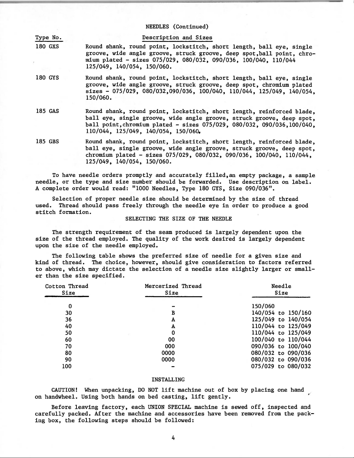
NEEDLES
(Continued)
Type No.
180
GXS
180
GYS
185
GAS
185
GBS
To
needle,
A
complete
Selection
used.
stitch
Round
groove,
mium
125/049,
Round
groove,
sizes -075/029,
150/060.
Round
ball
ball
110/044, 125/049,
Round
ball
chromium
125/049,
have
needle
or
the
type
order
of
Thread
formation.
should
shank,
wide
plated -sizes
140/054,
shank,
wide
shank,
eye,
single
point,chromium
shank,
eye,
single
plated -sizes
140/054,
orders
and
size
would
proper
pass
read:
needle
freely
Description
round
angle
round
angle
round
round
promptly
SELECTING
point,
groove,
075/029, 080/032,
150/060.
point,
groove,
080/032,090/036,
point,
groove,
plated -sizes
140/054,
point,
groove,
150/060.
and
number
"1000
should
Needles,
size
through
lockstitch,
lockstitch,
lockstitch,
wide
lockstitch,
wide
075/029,
accurately
should
the
THE
SIZE
and
Sizes
struck
struck
angle
150/060.
angle
080/032,
be
forwarded.
Type 180
be
determined
needle
OF
short
groove,
090/036,
short
groove,
100/040,
short
groove,
075/029, 080/032,
short
groove,
filled,an
GYS,
eye
THE
NEEDLE
length,
deep
length,
deep
110/044,
length,
struck
length,
struck
090/036,
empty
Use
Size
by
the
in
order
spot,ball
100/040,
spot,
description
090/036".
ball
eye,
single
point,
110/044
ball
eye,
chromium
125/049, 140/054,
reinforced
groove,
090/036,100/040,
reinforced
groove,
100/040,
package, a sample
size
of
thread
to
produce
chro-
single
plated
blade,
deep
spot,
blade,
deep
spot,
110/044,
on
label.
a good
The
size
of
upon
the
The
kind
of
to
above,
er
than
Cotton
CAUTION!
on
handwheel.
strength
the
thread
size
following
thread.
which
the
size
Thread
Size
0
30
36 A
40
50
60
70
80 0000
90
100
requirement
employed. The
of
the
table
The
may
dictate
specified.
When
unpacking,
Using
both
needle
shows
choice,
hands
of
the
quality
employed.
the
preferred
however,
the
selection
Mercerized
INSTALLING
DO
NOT
on bed
seam
should
Size
000
0000 080/032
lift
casting,
produced
of
the
size
give
of a needle
Thread
B 140/054
A 110/044
0
00
machine
is
largely
work
desired
of
needle
consideration
size
out
lift
gently.
of
dependent
is
largely
for a given
to
slightly
150/060
125/049
110/044
100/040
090/036
080/032
075/029
box by
placing
factors
larger
upon
the
dependent
size
and
referred
or
Needle
Size
to
150/160
to
140/054
to
125/049
to
125/049
to
110/044
to
100/040
to
090/036
to
090/036
to
080/032
one hand
small-
Before
carefully
ing
box,
leaving
packed.
the
following
factory,
After
the
machine and
steps
each
should
UNION
be
SPECIAL
accessories
followed:
4
machine
have
is
been
sewed
off,
removed from
inspected
the
and
pack-
Page 5
CLIIIIP
Foe
fA:>tt
':IOI..Et.aOI D vlti..VES
"'2E
3 ·
WAY
£ 4 'I¥Al
LEADS
<071F·I3
t;71 F·S
717
<;71
F· ll
Ee
R
lf()tJNf/116
SOlEIJOIO
RX>T
j
-10
<103
t
1111<;.
1'\.~EA!'>\
OF
ELECTeiCAL
PII.ET"'
01.1
EQUII'PE.O
Po'>ITIOIJt£!..
1\.I':>TI'\.\.Al\ON
1)
MO
U'-IT
""'
"'>\CWU.
Z)
MOUIJl
liiiDteS\tlE
SC·3Z~
A SCREWS
~)
MOOI.IT
REGUlA10R
LEF 1 R£-'11 ll<BI..E LE.(; .
IIJST.•lL
'I)
To
1"E
MA.C>III.I
t . P.
S)
PLI<Cii:
YOW
T
')
;3~
35 P
IF
....
-
FE
=~'!»\~[)
7)
C
OO<IJ
EC.T
8)
TO
DI
~COtJ~
L\
f:'T
, RO"'rtti
ll<t 3 •
IT W•TH
PLUEi
AS t•TI!A.
.-
lr!II(H
!IRC
JIIHE TO
•
/
RS
SHOWN
<;.\lOWS
11\E 1\.1';11<ll1<110\.l
A.IJ[) I'IJE\l"""11C
~Melo~\\.~t\.'(
WIT)\
BOo'fP-~2
eoo.,-P-~Z
SOLE.IJOIO
OF
'liE
MAC\III.IE
IIJ<;.H~UCT
EH.R
MA.C""'E
S
YIJC~IJI
fOOL
wr.; 1HE I>EFLtC10e PlATE
AOV:,
ALL
EC.T AI
"'"' •.;cu
(1\ • <071 F·c;.
sceew.
~[)
~ttliJ~E.
\JEEOLE
B~~ET
TABLE 130AeD
81!/loCKE.T
~"3470l.
A.CCESS
•
O"<;,
FU21o11'>\\tD
TO
Pl.·
~12.
o1.1
1\<
E ,\,jSo
ZE~
A>lD
TA.PE
-">JUST.
,.,_
RlE
~li~~~~~:I!\KIIOIJ"'
,.
~·1
\JS
E.,_
A~
~
10
l~E ~~S
"~C2' Ftlt'
\.l~
•
"'O
D V
,O.lVE
A!>t.I'Re
'"~"
,.
..
.,~
A.IJO
c...ec,• tlO<::O.
t;7HO
C#71C·I
~
t;71
F-9
.a.'>'>EK!ILY
1/Ai.l/€
11\I?EAD
~-375
1<.71
· 17
,a.';<;.El'ISLY
SOlEWOIO
"''"~''"'"..__
22~05
SECTIQI..l
A-A
L
~EGULA.TOR
~T
F..
,0.\ll.ILA.Bl.E.
·~~~
_:
'MlH
REGULA.Toe•c;7, o -7.
4WA.'f
---------------~
~E.T
.0.'>'1>E.I-I8LY
RtG~LA.TOI!
•
C.71
0 · 7
I~
CF
"Z'!l"BO!<L
A<;.
~~E&'T~~~~~c
1W
IJOT
I<JT,
EXT~
BUT
1
t~l=-::.-------=-=
.::::.-::,.
.
cr'
,..
...
7, f ·
!l
,-
"'I!·
Gi11 F·l'!.
/
FllTEI?
-1<.71F
1<.710
STIIJl
~
· 7 1
· 5
IYRSJI(RS
--
- l\JBII-IGt FRo>\ Tei.I
RELSASE
"t\o\E
-
"'
·
"'~
-GROOND
! '
SOLWOID
or
FOE
PRES'>U~
'HIPE'e. •
OF
"-~'f
~llJ..\1€
KU\f'€
.
WIRE
•J.'
f-----..,
!all!&
f.'
<;11!01"\l'IE. T TO
BE
SUI'f'I.IED
\IEEt".E I'OSii tOIJ
'OI0
\.1
SY
NOIRON!ZE
BRI/CKET.
?.·wA.Y
FOR
WITh
t;ROUND WJR£7fit:Jif
110
701<
fERJivrRL
.
~01'\PoutiJT
~~1.'\
IJ~EOLE
Po.,_I\IO
~U:
~"?.470'1'
TO
~\..C.
("\
TO
02 1
E.,_
A.~Cat!DIIJ(;
..,ITH
l~E
A.L<A.TIO>J
A.IJ[)
QlE<:I<I\l{:o
To
SEE
'i»>IWII
~Ee
,1\
Plt)O
F'
8 1
Qot'\
AIJD
IIEPUCE
,..., Vl.lZS71F
""'•
A.""'LA.Bl.-
ll'\
T
GI!EE\.1
<03"70Z
~to
WHITE.
E.\JLA.EGEO
>ne
T~E
?. ·
Te\6\0\.1
Ri.I.EASE.. SO...EIJOI[).
llJ..L
ELE<:lltiCAL. WIRE'!\
BE.
FA.'>lE.»ED
TI.BLE 80A.Rtl
VIEW
WA'f
OF
i " ·
5U:UI<!E.L'<
WIT\\
c...aLE
l\4£
WAY
ELEC.ll11c...L
50LE\JOIO
-""0
l'lO"Il:>R
10
~E
CLI<11P'!\
OlolNtC.
V,.LVE
"-110
CA.6l£.<;. MU'ST
INI:i£R·'!oiOE
I'I!OVIOEO.
Fig.
,,
TICIJS
eF
TilE
~
1KE:
1
IITTIICH
FOR
~sz
u-1+-
18j
,
<0'2.7
ZIC.57E
MOJ.ITI\.IG.
OF
RE.GU~"TO'e
~I<.E.T
lAI!U.
-oo
IIETII!N/NG
SrlfCHIIOII'IZ£R PLUG.
WJIIE
'60Af.'0
I.IEEDLE I'OSI"t\0\.IE'il ~~~E
S~O
ee.
"'ET
iO
UIJE.
TO
!tOll
"-\.l<i.LE
BE
WILL !lot PULLED
iO
ALI.DW
lO
'ltES l 1'0"'1"110\..l
l..OCJI.TE.
\JEEDLE f'O!.ITI0\1;1'!
SO
TI<E.
K.TUI\n\lc;.
I~
A
s"I'R,o."-111
ROD
Mot\oC~I'-IE
Bl!o\C:.l<ET
"""""'
liLTEO
OVE12
TeE.A.t>LE
\.!
B":"-
Page 6
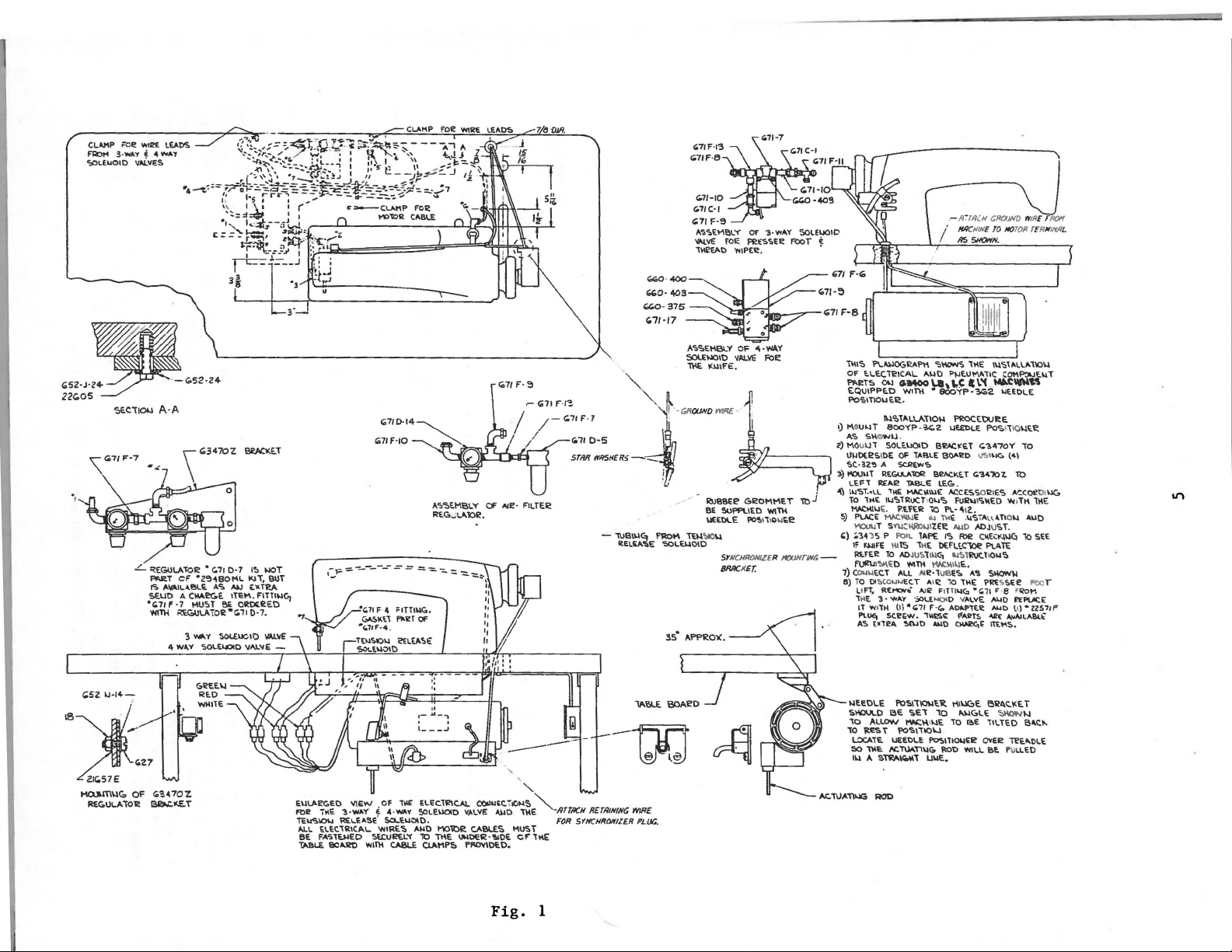
PREPARATION
OF
MACHINE
AND
TABLING
Included
bobbin
spring,
screw,
kit
for
sisting
two
hinge
one
synchronizer
er
lead
1.
Preparation
ing,
(a)
(b)
winder
one
four
"KLIPP-IT"
of
wire
Fasten
per
Cut
with
assembly,
knee
lifter
isolator
one
frame
studs,
two
bracket,one
clamp and clamp
of
turn
up
side
the
(Fig.
length
cylinders
(c)
Wire
(d)
Attach
(e)
Attach
(f)
2.
Machine Mounting Frame
leads
front
tions
Secure
frame
leg
electro
wire
that
electrical
using
each
machine
the
assembly
pads
and
thread
thread
screws
Electro
down
solenoid
1).
of
air
tubing
as
per
(Fig.
with
of
stripped
table
drive
coming from
come
with
cable
clamps and
is
machine
and
clips,
trimmer,
eyelet,
for
holding
synchronizer
for
tension
Drive
and
and
install
valves
desired
1).
ends
frame.
to
underside
switch
electro
and
screws
Installation.
a box
of
mounting
its
rubber
one
machine
also
one
included
eyelet
miscellaneous
release
Pneumatic
the
and
filter
and
to
switch
box
drive.
leads
provided.
STANDARD
frame,
pad,
rest
attaching
lead
wire
Accessories
following.
regulator
connect
box and mount
of
table.
to
electric
to
underside
Insert
ACCESSORIES-containing one
one
oil
bed
pin
is a bag
attachment
clamp,
solenoid
assemblies
all
drive
of
all
drain
positioning
and
of
screw,
one
lead
Kit
solenoid
as
tableboard
plugs
jar
and
spring
pneumatic
assembly
one
screw
to
parts,
extra
the
for
wire.
with a suitable
to
the
valves
switch
box
outlined
and
(Fig.
its
clamp
and
accessories
con-
bobbin,
bed
plate,
synchroniz-
table
and
air
to
right
in
instruc-
to
table
1).
tabl-
as
NOTE:
(a)
On a suitable
(21393
Insert
ly.
round
(21393
ly
(Fig.
(b)
Insert
(c)
Assemble
(d)
Place
1/16
sides,
grip
(e)
Tip
assembly
cone
(f)
Before
knee
set
fere
screw
63400
If
this
tableboard,
N)
in
the
the
countersunk
Assemble bed
head
wood
R)
to
outside
1A)
•
hinge
sewing
inch
rap
on
the
machine
bearings,
the
lifter
so
that
with
so
LB,
can
the
(1.59
the
the
underside
as
shown.
machine
rod
the
moving
that
LY
not
studs
upper
head
retaining
but
the
and
be
machine
wood
positioning
screw
and
front
in
holes
frame
in
the
mm)
clearance
of
back
against
All
end
must
is
put
should
be
maximum
parts
within
presser
1/2
inch
obtained
turn
cut-out
screw
tighten
of
provided
eyelet
frame
plate
the
play
not
bind
into
adjusted.
lift
bar
(12.70
check
right
with
through
spring
securely.
pan
section,
to
top
mounting,
between
smartly
board
the
rest
of
and
the
(Fig.
production,
The
of
the
presser
the
head.
raises
mm)
Presser
side
up
place
the
hinge
left
hinge
(63474
A)
over
Assemble
as
shown, and snug up
for
them
in
of
arm.
and
after
the
cloth
upward
tighten
pin,
cross
with
and
shaft
locking
assemble
1A).
the
bell
left
stop
bar
This
may
approximately
on 63400
Bar
Connection
LC.
machine
lugs
right
rear
being
plate
a hammer
should
screw
and
be
5/16
to
the
pad and
the
of
edge
nuts
the
crank
(22597 F)
its
parts
done
inch
page
mounting
rear
tighten
hinge
retaining
cloth
sure
there
a~1
to
securely.
knee
be
taken
(21665
do
by
setting
(7.93
9.
(Fig.
pad;
nuts
plate.
the
frame
insure
press
up
J)
should
not
mm)
frame
1A).
secureinsert
plate
light-
is
about
a good
by
of
the
interthe
stop
on
the
be
(g)
These
belt
machines
and
adjust
are
equipped
electro
drive
to
as
use
either
shown on
6
Ill
(Fig.
"Vee"
1).
or
round
belts.
Install
Page 7
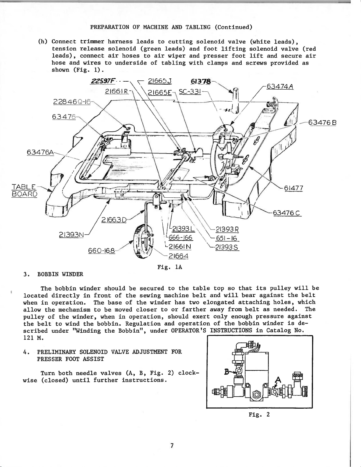
(h)
Connect
tension
leads),
hose
and
shown
PREPARATION
trimmer
release
connect
wires
(Fig.
1) .
22597F---
harness
solenoid
air
hoses
to
underside
OF
MACHINE
leads
(green
to
air
of
AND
to
cutting
leads)
wiper
tabling
TABLING
solenoid
and
foot
and
presser
with
clamps and
(Continued)
valve
lifting
foot
screws
(white
solenoid
lift
and
provided
leads),
valve
secure
(red
air
as
TABLE
BOARD
---
3.
22846Q-1
6347
BOBBIN
6
6
" }
213931\J
660-168
WINDER
216630
Fig.
61477
1A
The
located
when
allow
pulley
scribed
4.
wise
in
the
of
the
belt
121
M.
PRELIMINARY
PRESSER
Turn
(closed)
bobbin
directly
operation.
mechanism
the
winder,
to
wind
under
FOOT
both
"Winding
needle
until
winder
in
the
SOLENOID
ASSIST
should
front
The
to
be
when
bobbin.
the
valves
further
of
the
base
of
moved
in
Regulation
Bobbin",
VALVE
(A, B,
instructions.
be
secured
sewing
the
closer
operation,
ADJUSTMENT
machine
winder
to
under
Fig.
to
the
has
two
or
farther
should
and
operation
OPERATOR'S
FOR
2)
clock-
7
table
belt
exert
top
and
elongated
away from
only
of
INSTRUCTIONS
so
will
enough
the
that
its
bear
attaching
bobbin
belt
pressure
in
Fig.
against
as
winder
pulley
holes,
needed.
Catalog
2
will
the
belt
which
The
against
is
de-
No.
be
Page 8
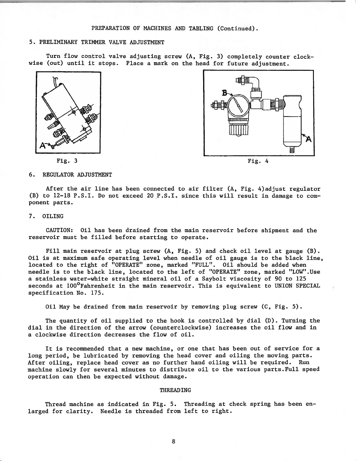
5.
PRELIMINARY
PREPARATION
TRIMMER
VALVE
OF
MACHINES
ADJUSTMENT
AND
TABLING
(Continued).
Turn
wise
6.
(B)
ponent
7.
(out)
REGULATOR
After
to
OILING
flow
until
Fig.
the
12-18
parts.
control
it
stops.
3
ADJUSTMENT
air
line
P.S.I.
Do
valve
has
not
exceed 20.
adjusting
Place
been
connected
screw
a mark on
P.S.I.
(A,
the
to
since
air
Fig.
head
filter
this
3)
completely
for
future
(A,
will
adjustment.
Fig.
Fig.
result
counter
4
4)adjust
in
damage
clock-
regulator
to
com-
CAUTION:
reservoir
Fill
Oil
is
at
located
needle
a
stainless
seconds
specification
dial
a
clockwise
long
After
machine
operation
to
is
at
Oil
May
The
quantity
in
the
It
is
period,
oiling,
slowly
Oil
has
must
main
maximum
can
be
filled
reservoir
safe
the
right
to
the
black
water-white
100°Fahrenheit
No.
175.
be
drained
of
direction
direction
recommended
be
lubricated
replace
for
several
then
be
been
before
at
operating
of
"OPERATE"
line,
straight
in
from
oil
supplied
of
the
decreases
that
by
head
expected
cover
minutes
drained
starting
plug
a new
screw
level
located
mineral
the
main
main
arrow
the
removing
as
without
from
zone,
reservoir
to
(counterclockwise)
flow
machine,
no
to
the
main
to
operate.
(A,
Fig.
when
to
reservoir.
the
the
further
distribute
damage.
THREADING
needle
marked "FULL".
the
left
oil
of a Saybolt
by
removing
hook
of
oil.
or
head
is
one
hand
cover
reservoir
5)
and
of
oil
of
"OPERATE"
This
oil
is
controlled
increases
that
has
and
oiling
to
before
check
Oil
plug
the
oil
gauge
should
viscosity
equivalent
screw
by
been
oiling
will
various
level
is
zone,
dial
the
out
the
be
shipment
at
to
the
be
added
marked "LOW".Use
of
90
to
UNION
(C,
Fig.
(D).
oil
of
service
moving
required.
parts.Full
and
gauge
black
when
to
5).
Turning
flow
parts.
the
(B).
line,
125
SPECIAL
the
and
in
for
Run
speed
a
Thread
larged
for
machine
clarity.
as
indicated
Needle
is
threaded
in
Fig.
5.
from
8
Threading
left
to
at
right.
check
spring
has
been
en-
Page 9
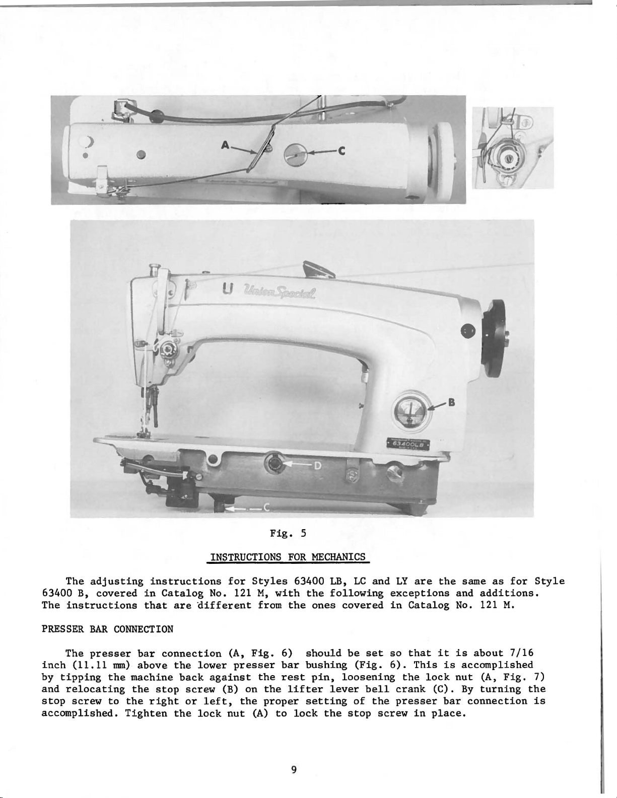
Fig.
5
The
adjusting
63400 B,
The
PRESSER
The
inch
by
tipping
and
relocating
stop
accomplished.
covered
instructions
BAR
presser
(11.11
the
screw
to
instructions
in
Catalog
that
are
CONNECTION
bar
connection
mm)
above
machine
the
the
Tighten
the
stop
right
the
different
lower
back
screw
or
lock
INSTRUCTIONS
for
Styles
No. 121
against
(B)
left,
(A,
Fig.
presser
on
the
nut
(A)
M,
with
from
the
the
proper
to
FOR
63400
the
6)
bar
rest
lifter
lock
the
should
bushing
setting
MECHANICS
LB,
LC
following
ones
pin,
covered
be
loosening
lever
the
stop
(Fig.
bell
of
9
and
exceptions
in
set
so
6).
the
screw
LY
are
Catalog
that
This
the
lock
crank
presser
in
the
same
and
No. 121
it
is
is
accomplished
nut
(C).
By
bar
place.
as
for
additions.
M.
about
connection
7/16
(A,
Fig.
turning
Style
7)
the
is
Page 10
PRESSER
BAR
GUIDE
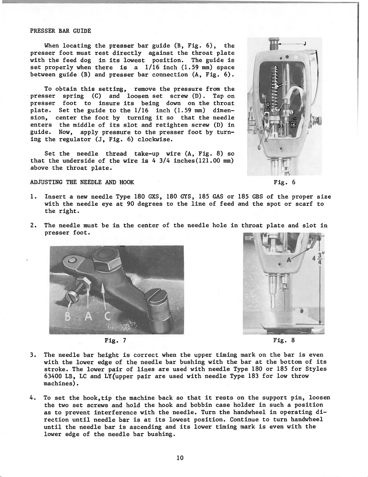
When
presser
with
set
between
foot
the
properly
guide
To
obtain
presser
presser
plate.
sion,
enters
guide.
ing
that
above
the
Set
the
the
Set
center
the
Now,
regulator
the
ADJUSTING
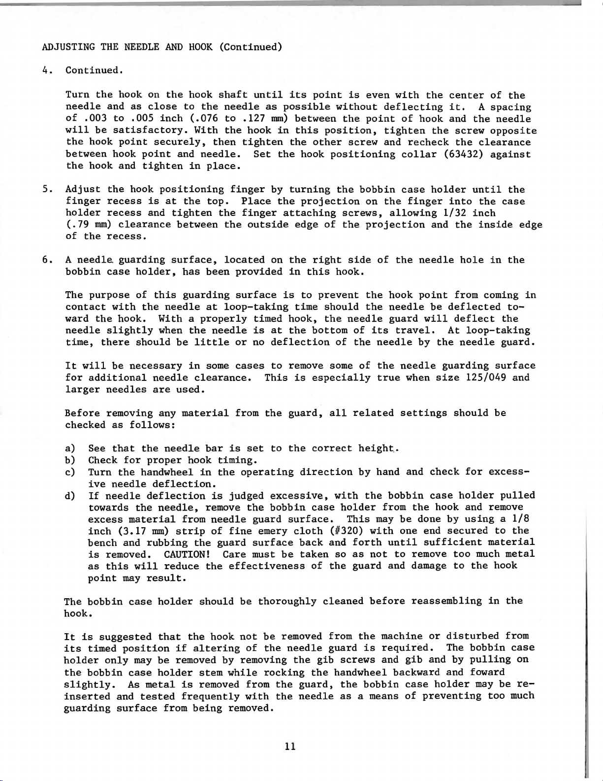
1.
Insert
with
the
right.
locating
must
feed
dog
when
(B)
this
spring
foot
the
to
guide
the
middle
apply
needle
underside
throat
THE
NEEDLE
a
new
the
needle
the
presser
rest
directly
in
its
there
and
presser
setting,
(C) and
insure
to
foot
by
of
its
pressure
(J,
Fig.
thread
of
the
plate.
AND
needle
eye
bar
lowest
is
a
bar
remove
loosen
its
being
the
1/16
turning
slot
and
to
6)
clockwise.
take-up
wire
HOOK
is 4 3/4
Type 180
at
90
degrees
guide
against
position.
1/16
inch
connection
the
set
down
inch
it
so
retighten
the
presser
wire
GXS,
180
to
(B,
Fig.
the
throat
The
guide
(1.59
(A,
mm)
Fig.
pressure
screw
(1.59
that
(D).
on
the
mm)
the
screw
foot
by
(A,
Fig.
inches(121.00
GYS,
the
185
line
6),
plate
space
from
Tap
throat
dimenneedle
(D)
turn-
8)
GAS
of
the
is
6).
the
on
in
so
mm)
or
feed
185
and
GBS
the
Moli-----
Fig.
of
spot
the
6
proper
or
J
scarf
size
to
2.
The
presser
3.
The
with
stroke.
63400
machines).
4.
To
the
as
rection
until
lower
needle
needle
the
LB,
set
two
to
prevent
the
edge
foot.
lower
The
the
set
until
must
be
Fig.
bar
height
edge
lower
LC
pair
and LY(upper
hook,tip
screws
interference
needle
needle
of
the
bar
needle
in
of
the
and
bar
is
the
center
7
is
correct
the
needle
of
lines
pair
machine
hold
with
is
ascending
bar
of
when
are
are
back
the
hook and
the
at
its
bushing.
the
bar
used
used
so
needle.
lowest
and
needle
the
upper
bushing
with
with
that
bobbin
position.
its
lower
hole
with
needle
needle
it
Turn
in
timing
the
Type 183
rests
case
the
Continue
timing
throat
mark
bar
on
at
Type 180
for
on
the
support
holder
in
handwheel
to
mark
is
plate
the
the
or
Fig.
bar
bottom
185
low
and
8
is
for
throw
pin,
slot
even
of
Styles
loosen
such a position
in
operating
turn
handwheel
even
with
the
in
its
di-
10
Page 11
ADJUSTING
4.
Continued.
THE
NEEDLE
AND
HOOK
(Continued)
5.
6.
Turn
needle
of
will
between
Adjust
finger
holder
of
A
bobbin
The
contact
ward
needle
time,
It
for
larger
.003
the
the
(.79
the
needle
will
the
be
hook
hook and
mm)
purpose
the
there
additional
hook on
and
as
close
to
.005
satisfactory.
point
hook
the
recess
recess
clearance
recess.
guarding
case
with
hook.
slightly
be
needles
securely,
point
tighten
hook
is
and
holder,
of
this
the
should
necessary
needle
are
the
hook
shaft
to
the
needle
inch
positioning
With a properly
when
(.076
and
in
at
the
tighten
between
surface,
has
guarding
needle
the
be
in
used.
to
With
the
then
needle.
place.
finger
top.
the
the
located
been
provided
surface
at
loop-taking
needle
little
clearance.
some
or
cases
until
as
.127
hook
tighten
Set
Place
finger
outside
timed
is
no
This
its
point
possible
mm)
between
in
this
the
other
the
hook
by
turning
the
projection
attaching
edge
on
the
right
in
this
is
to
time
hook,
at
the
bottom
deflection
to
remove some
is
especially
is
without
the
position,
screw
positioning
the
screws,
of
the
side
hook.
prevent
should
the
needle
of
of
the
even
with
deflecting
point
tighten
and
bobbin
on
the
allowing
projection
of
the
the
hook
the
needle
guard
its
travel.
needle
of
the
true
the
of
hook
recheck
collar
case
finger
needle
point
will
by
needle
when
center
it.
and
the
screw
the
(63432)
holder
into
1/32
and
the
from
be
deflected
deflect
At
the
guarding
size
of
A
spacing
the
needle
opposite
clearance
against
until
the
case
inch
inside
hole
needle
in
coming
the
loop-taking
guard.
surface
125/049
the
the
edge
the
in
to-
and
Before
checked
a)
See
b)
Check
c)
Turn
ive
d)
If
towards
excess
inch
bench
is
as
point
The
bobbin
hook.
It
is
suggested
its
timed
holder
the
bobbin
slightly.
inserted
guarding
removing
as
follows:
that
needle
needle
removed.
this
only
the
for
the
handwheel
the
material
(3.17
and
will
may
case
position
may
case
As
metal
and
tested
surface
any
material
needle
proper
deflection.
deflection
mm)
rubbing
result.
hook
needle,
from
strip
CAUTION!
reduce
holder
that
the
if
be
removed
holder
is
frequently
from
bar
timing.
in
the
is
remove
needle
of
the
guard
Care
the
should
hook
altering
by
stem
removed
being
from
the
is
set
to
operating
judged
fine
effectiveness
be
not
removing
while
removed.
excessive,
the
bobbin
guard
emery
surface
must
thoroughly
be
of
the
rocking
from
the
with
the
be
removed
guard,
the
correct
direction
case
surface.
cloth
back
taken
of
needle
the
gib
the
guard,
needle
all
related
height
by
with
holder
This
(#320)
and
forth
so
as
the
guard
cleaned
from
guard
the
screws
handwheel
the
as
a means
hand
the
bobbin
from
may
with
until
not
and damage
before
machine
is
required.
and
bobbin
settings
..
and
check
case
the
be
done
one
end
sufficient
to
remove
reassembling
or
gib
and
backward
case
holder
of
preventing
should
holder
hook
and
by
using a 1/8
secured
too
to
disturbed
The
by
and
for
excess-
remove
material
much
the
in
bobbin
pulling
foward
may
too
be
pulled
to
the
metal
hook
the
from
case
be
much
on
re-
11
Page 12
ADJUSTING
THE
NEEDLE
AND
HOOK
(Continued)
HOOK
ADJUSTING
1.
Check
CAUTION!
2.
3.
1.
OILING
damage
With
inch
tinue
definite
Should
front
the
change
be
run
Check
rise
teen
throat
oil
flow
Do
may
the
bobbin
(50.80 x 101.60
running
and
more
of
the
for
FEED
height
.040
or
less
plate.
to
hook.
not
run
result,
case
the
machine.
distinct
or
less
machine
required.
about
MECHANISM,
to
of
feed
.045
teeth
one
inch
the
machine
and
needle
in
the
hook,
mm)
piece
After
pattern
oil
be
required
just
below
After a change
minute
For
dog.
to
the
Styles
(1.02
inch
before
Feed
to
without
positioner
run
of
white
about
of
oil
spots
turn
the
cloth
in
checking
63400
dogs
1.14
should
having
mm)
the
paper
five
the
LB
rise
the
bobbin
adjusted
machine
directly
seconds,
should
the
hook
plate
hook
for
and
LC
twenty
above
the
throat
depth
case
for
one
be
observed.
oil
surface,
oil
flow,
desired
two
of
in
proper
full
minute.
under
remove
control,
in
the
oil
teeth
plate.
the
the
top
the
the
located
the
machine
flow.
per
Those
teeth
hook
as
speed.
Place
hook and
paper
direction
inch
should
having
above
hook
a 2 x 4
con-
and a
on
the
of
should
six-
the
.
At
their
the
line
2.
Adjust
3.
Set
stitch
a)
Press
b)
Holding
the
eccentric.
c)
Lengthening
operating
d)
Shortening
opposite
e)
Release
ADJUSTING
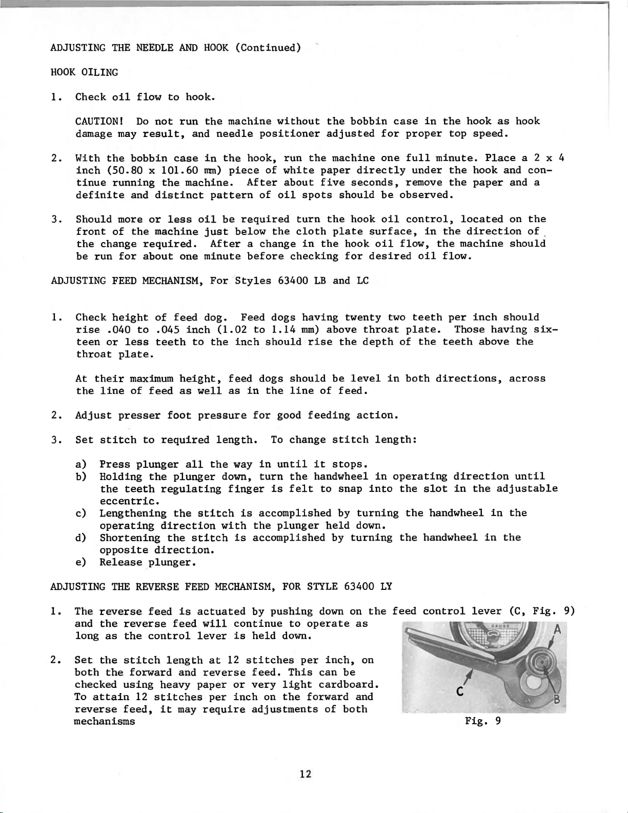
1.
The
reverse
and
the
long
2.
Set
the
both
checked
To
attain
reverse
mechanisms
presser
THE
reverse
as
stitch
the
using
feed,
maximum
of
feed
to
plunger
the
teeth
direction.
plunger.
REVERSE
feed
the
control
forward
12
stitches
height,
as
well
foot
required
regulating
direction
the
length
heavy
it
pressure
all
plunger
the
stitch
stitch
FEED
is
actuated
feed
will
lever
and
reverse
paper
may
require
feed
as
length.
the
down,
finger
with
MECHANISM,
at
12
per
dogs
in
for
way
in
turn
is
accomplished
the
is
accomplished
by
continue
is
held
stitches
feed.
or
very
inch
on
adjustments
should
the
line
good
To
change
until
the
is
felt
plunger
FOR
pushing
to
down.
This
light
the
be
of
feeding
stitch
it
stops.
handwheel
to
by
held
by
STYLE
down
operate
per
inch,
can
cardboard.
forward
of
level
feed.
action.
snap
turning
down.
turning
63400
on
as
be
and
both
length:
in
into
the
on
in
both
operating
the
the
the
LY
feed
directions,
direction
slot
in
handwheel
handwheel
control
lever
Fig.
the
adjustable
in
in
9
across
until
the
the
(C,
12
Page 13
ADJUSTING
2.
Continued
THE
REVERSE
FEED
MECHANISIM,
FOR
STYLE
63400
LY
(Cpntinued)
After
directions,
other.
"Adjusting
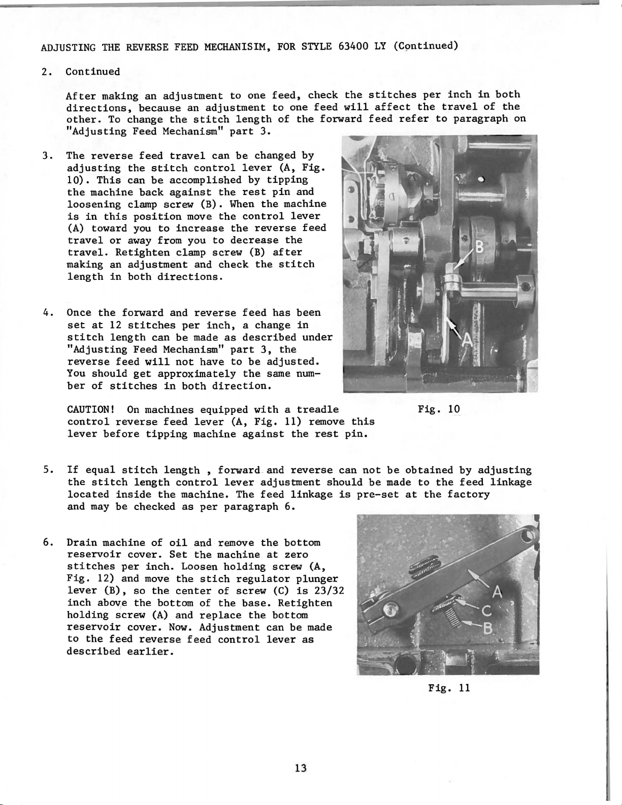
3.
The
adjusting
10).
the
loosening
is
(A)
travel
travel.
making
length
4.
Once
set
stitch
"Adjusting
reverse
You
ber
making
To
reverse
This
machine
in
this
toward
or
Retighten
an
in
the
at
12
length
feed
should
of
stitches
an
adjustment
because
change
Feed Mechanism"
feed
the
stitch
can
be
back
clamp
position
you
away from you
adjustment
both
directions.
forward
stitches
can
Feed Mechanism"
will
get
an
the
stitch
travel
control
accomplished
against
screw
move
to
increase
clamp
and
and
reverse
per
be
made
not
approximately
in
both
to
one
feed,
adjustment
length
part
can
the
(B).
When
the
to
screw
check
inch, a change
as
have
direction.
3.
be
changed
lever
by
tipping
rest
the
control
the
reverse
decrease
(B)
the
feed
described
part
3,
to
be
adjusted.
the
same num-
to
one
of
the
(A,
pin
and
machine
lever
the
after
stitch
has
been
in
the
check
feed
forward
by
Fig.
feed
under
the
will
stitches
affect
feed
refer
per
the
inch
travel
to
paragraph
in
of
both
the
on
5.
6.
CAUTION!
control
lever
If
the
located
and
Drain
reservoir
stitches
Fig.
lever
inch
holding
reservoir
to
described
before
equal
stitch
may
machine
12) and move
(B),
above
the
feed
On
machines
reverse
tipping
stitch
length
inside
be
checked
cover.
per
inch.
so
the
screw
cover.
reverse
earlier.
equipped
feed
lever
machine
length , forward
control
the
of
oil
Set
the
center
bottom
(A)
and
Now.
machine.
as
Loosen
the
feed
lever
per
paragraph
and remove
the
machine
holding
stich
of
of
the
replace
Adjustment
control
with a treadle
(A,
Fig.
against
and
adjustment
The
feed
the
at
screw
regulator
screw
base.
the
(C)
Retighten
bottom
can
lever
11) remove
the
rest
reverse
should
linkage
6.
bottom
zero
(A,
plunger
is
23/32
be
made
as
this
pin.
can
is
not
be
be
made
pre-set
Fig.
obtained
to
the
at
the
Fig.
10
by
adjusting
feed
factory
11
linkage
13
Page 14
ADJUSTING
7.
On
machines
lever
lever
to
stop
this
to
the
actuated
is
THE
REVERSE
(A,
Fig.
(B,
Fig.
against
position
feed
FEED
equipped
11),
9) and
the
with
adjusting
by
stepping
MECHANISIM,
with a treadle
hold
down
bed
lock
adjust
casting.
nut
screw,
on
the
(C).
when
the
the
reverse
stop
Lock
This
reverse
treadle.
FOR
STYLE
control
screw
stop
is
feed
screw
to
feed
63400
reverse
control
(B,
Fig.
(B)
prevent
is
LY
(Continued)
feed
11)
in
damage
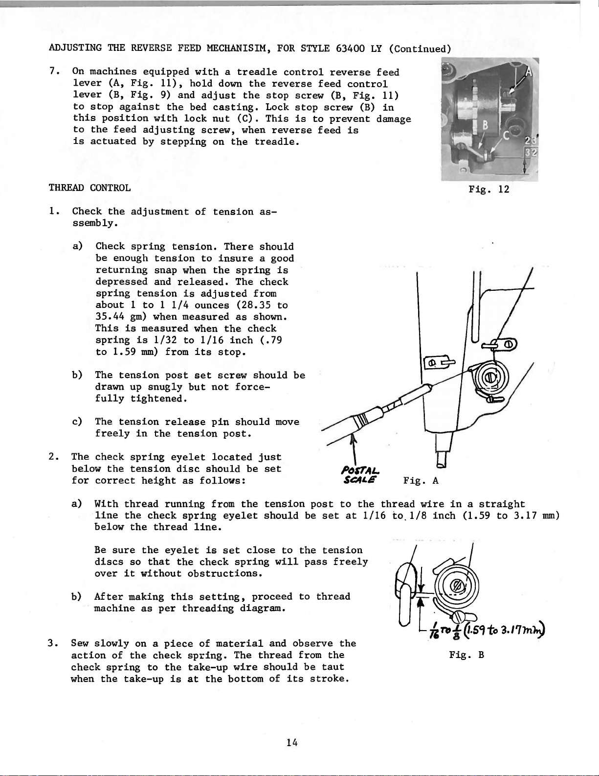
THREAD
1.
Check
ssembly.
a)
b)
c)
2.
The
below
for
CONTROL
the
adjustment
Check
be
returning
depressed
spring
spring
enough
tension
tension.
tension
snap
and
about 1 to 1 1/4
35.44
This
spring
to
The
drawn up
fully
The
freely
check
correct
is
1.59
tension
tension
the
gm)
when
measured
is
1/32
mm)
from
post
snugly
tightened.
release
in
the
spring
eyelet
tension
height
of
tension
to
when
the
released.
is
adjusted
ounces
measured
when
to
1/16
its
set
but
not
pin
tension
located
disc
as
follows:
should
There
insure
spring
The
(28.35
as
the
inch
stop.
screw
force-
should
post.
as-
should
a good
check
from
shown.
check
(.79
should
just
be
set
is
to
move
be
Fig.
A
Fig.
12
a)
3.
With
below
Be
discs
over
b)
After
machine
Sew
slowly
action
check
when
line
spring
the
thread
the
the
sure
so
it
making
of
the
take-up
check
thread
the
that
without
as
per
on a
check
to
running
spring
line.
eyelet
the
check
obstructions.
this
setting,
threading
piece
of
spring.
the
take-up
is
at
from
eyelet
is
set
material
the
bottom
the
tension
should
close
spring
proceed
diagram.
The
thread
wire
should
to
will
and
of
post
be
the
pass
to
observe
from
be
its
stroke.
to
set
tension
freely
thread
the
the
taut
at
14
the
1/16
thread
to.1/8
wire
inch
in a straight
(1.59
Fig.
to
B
3.17
mm)
Page 15

THREAD
3.
Continued
CONTROL
(Continued)
Slight
reasonable
The
tension
tension.
men~,
tension
changes
machines
on
but
can
tension
are
70-2
The
check
this
be
in
needle
should
sewn
cord
is a required
reduced.
off
or
similar
spring
thread
be
at 3 to 4 ounces
CB'I
used
will
setting
tension
to
thread.
feel
may
be
maintain a uniform
(85.05
Depress
heavy
for
I I
to
the
I
necessary
to
check
you when compared
63400 and
at
this
and
consistent
113.40
gm)
spring
as a result,
~
needle
when
to
point
checking
61400
the
but
a
stitch.
thread
adjust-
disc
the
PRESSURE
The
formly.
(61457 B
wise
TENSION
3.
1.
2.
Tension
decreases
Set
centered
Solenoid
lease
a minimum
(1.59
sembly
ine
screw
(.127
tension
ON
MATERIAL
presser
To
or
RELEASE
the
pin
mm).
in
arm and moving
release
in
mm)
disc.
spring
increase
63457
tension
N)
the
on
the
plunger
and
the
of
1/32
If
or
out
bracket.
clearance
pressure.
assembly
check
pin
adjustment
by
solenoid
should
the
pressure
in a clockwise
(E,
end
inch· (.79
loosening
stop
Solenoid
between
so
spring
Fig.
of
solenoid
is
screw
is
exert
that
eyelet
mm)
required
secured
plunger
it
Fig.
only
on
direction.
14) must
to a maximum
set
(B,
and
the
presser
the
tension
(A,
plunger
move
screw
Fig.
to
pin
the
C
enough
flat
Turning
Fig.
touch
pin
tension
located
13)
as
of
(E)
is
tension
pressure
foot,
discs
13).
tension
must
of
required.
turn
are
protrude
1/16
post
under
bushing
to
have
release
to
make
the
spring
the
regulator
reinch
as-
mach-
(F,
Fig.
approximately
pin
without
the
work
regulator
counterclock-
Fig.
14)
with a set
thread
feed
.005
13
inch
in
uni-
the
15
Page 16

TENSION
3.
Continued
RELEASE
(Continued)
This
spacer
end
should
it
taken
tension
4.
The manual
so
presser
The
and
ions.
to
the
NOTE:
oil
wick
The
wick
gauge
can
between
of
tension
then
contacts
not
that
tension
then
The
5/16
throat
Head
in
must
to
be
be
accomplished
be
the
to
exert
disc.
tension
it
will
foot
is
cam
raising
average
inch
(6.35
plate.
oiler
the
bracket
center
contact
sure
it
the
head
release
slipped
solenoid
too
After
release
not
release
raised
can
be
or
lowering
tension
to
Tighten
of
the
reads
by
placing
of
solenoid
pin.
The
onto
bushing
plunger
much
pressure
tightening
cam
thread
for
back
positioned
released
7.94
mm)of
screw
must
the
needle
full
locate
slot
bearings.
and
tension
pin.
set
(G,
tacking.
to
suit
presser
securely.
in
operates
a
.005
plunger
and moved
Care
thereby
screw
Fig.
tension
by
loosening
the
point
the
needle
the
connecting
inch(.127
pin
release
should
remove
14)
should
when
sewing
is
between
foot
Check
freely.
and
solenoid
in
until
opening
spacer.
the
screw
condit-
lift
bar
link
rod.
the
oil
TRIMMER
mm)
the
be
the
be
set
(H)
1/4
above
ADJUSTMENTS
Mil-----
Fig.
J
14
2.
knife
to
raise
Position
ing
finger.
If
this
(F)
until
pin
hole
side
of
Adjust
turn
it.
Fig.
upper
is
not
the
in
the
lower
flange
15
knife
Check
so,
knives
the
arm
knife
screw
(D)
to
see
loosen
are
eccentric
of
the
until
(G,
bly
1.
c
parallel
that
the
parallel.
bushing
positioning
it
Fig.
the
finger
just
15)
Remove
from
machine
There
knife
ment
the
can
pivot
excessive
the
case
with
the
lower
set
A good
(F)
located
finger
contacts
clockwise
the
positioning
should
pivot
be
release
end
may
left
knife
screw
starting
(Fig.
the
to
and
proceed
be
no
bind
carrier
made by
(A,
loosening
lever
play
or
be.
side
of
the
is
parallel
(E) and
turn
point
approximately
17).
upper
lower
knife.
knife
finger
or
Fig.
as
follows:
shake
and
15).
screw
(C)
and
relieving
arm
of
with
would
and
the
the
eccentric
be
90°
to
To
adjust
counterclockwise
knife
in
lower
This
(B) on
taking
the
bind
the
position-
upper
to
have
the
right
the
assem-
adjustup
the
as
knife.
bushing
the
lower
16
Page 17

TRIMMER
2.
Continued
ADJUSTMENTS
(Continued)
CAUTION!
justment
Fig.
finger
and
as
position
Be
sure
will
have
16
indicated
knife.
bushing
to
D
at
is
not
be
checked.
The
should
sitioning
adjustment
after
#5).
cutting
point
not
the
As
edge
(D).To make
turned
lower
extend
finger
will
trUnmer
the
lower
(C)
while
Fig.
knife
beyond
(B).
need
has
must
17
(A,
If
to
been
knife
coincide
these
making
Fig.
lower
be
moves
16)
the
left
made
assembled
adjustments
this
adjustment
in
its
side
of
knife
to
at a point
to
the
the
extends
trUnmer and
to
right,
loosen
extreme
the
beyond
the
machine
of
or
Fig.
left
arm
the
run
the
positioning
screws
parallel
18
position
of
the
this
air
cylinder
(See
out
(A,
po-
point
Item
of
Fig.
ad-
the
17)
3.
Assemble
case
a)
b)
c)
d)
e)
positioning
holder
Fig.
With
air
Tip
machine
Loosen
Adjust
(.127
This
out.
Position
with
holding
mm)
is
the
positioning
19
to
the
back.
screw
piston
done by
Retighten
in
(B,
mimimum
lower
left
place
finger
finger
machine
Fig.
rod
(C,
between
loosening
nut
knife
side
of
tighten
19.)
Fig.
after
(A,
the
and
knife
and
holder
the
finger
tighten
screw
ance
the
4.
5.
on and
20)
nut
nut
.005
Fig.
arm
screw
assembly
knife
projection
securely,
between
inside
Locate
as
line
If
the
finger,
be
electrical
to
(C,
(C) and
16)
of
until
into
the
far
of
the
left
made
stop
Fig.
(.127
in
the
(B,
assembly
edge
the
back
lower
Fig.
into
by
the
finger
(A,
Fig.
the
bobbin
finger
the
feed.
side
the
to
19)
turning
mm)
its
positioning
and
allowing
outside
of
bobbin
knife
as
possible
knife
of
following
the
tr~er
power
internally
and
space
extreme
19).
machine.
turning
recess
18) on
case
knife
1/32
edge
case
cylinder
(A,
the
arm
adjustment
off.
by
air
cylinder
the
piston
has
been
left
finger
Adjust
the
is
the
holder
assembly
inch
of
recess
bracket
and
parallel
Fig.
16)
of
the
and
air
leaving
rod
obtained.
position
(B)
the
bobbin
at
the
positioning
recess
attaching
(.79
mm)
projection
(Fig.
(A,
extends
positioning
will
cylinder.
.005
(D).
in
or
to
While
bobbin
case
top.
(B) and
clearand
18).
Fig.
with
beyond
need
inch
line
Place
19)
the
to
up
17
Page 18

TRIMMER
6.
Adjust
extreme
left
does
7.
Be
sure
out
wire
8.
The
has
from
off).
er
Foot
not
ADJUSTMENTS
the
lower
right
side
not
the
when
does
knife
become
opening
To
Assist
the
same
of
the
hit
the
spring
the
lower
not
return
critical.
up and
adjust
as
hand
make
Adjustment.
{Continued)
knife
needle
hook
spring
for
used
stop
position,
slot
point.
retainer
knife
contact,
is
(A,
The
interfering
the
slowest
on 63400
screw
the
in
wire
in
bend
Fig.
spring
NOTE:
KA,
(B,
left
the
(B,
its
extreme
retainer
20)
itself
with
knife
Knife
KB
Fig.
corner
bobbin
Fig.
may
be
is a safety
the
hook
return,
return
and
KC.
20)
so
when
(E,
Fig.
case
holder.
17)
enters
right
wire
removed when
hand
to
suit.
(if
the
see
Final
spring
the
16)
CAUTION!
the
bobbin
position.
bobbin
device
air
Trimmer
on 63400
lower
is
to
compressor
knife
in
line
Be
case
If
over-spinning
prevent
Valve
LB,
LC
with
sure
holder
the
the
should
and
and
is
in
the
knife
spring
knife
Press-
LY
its
cut-
be
are
Fig.
20
18
Page 19

800 YP-362
NEEDLE
POSITIONER
SETTINGS
TRANSFORMER
1.
Measure
2.
Disconnect
3.
Remove
CAUTION!
CONNECTIONS
line
bottom
Transformer
when removing
NOTE:
4.
Dummy
not
being
Connector
sponding
be
connected
tween .175-199
voltage
unit
from power
cover
taps
or 'replacing
connector
used,
and
lead
to
line
voltage.
to
the
VAC,
with
volbmeter.
source.
from
control
(A,
Fig.
connectors
(B)
MUST
to
prevent
(C) must
Examples:
tap
marked 215-229
remove
dummy
box.
21)
remain
any
be
connected
connector
are
very
(B
or
C).
on
the
possible
If
line
as
flexible
transformer
damage
to
the
proper
voltage
shown.
(B)
and
and
tap
to
unit.
measured
Should
connect
care
should
be
marked 175-199 when
transformer
219
line
voltage
(C)
to
tap
VAC,
tap.
(C)
measure
taken
corre-
should
be-
1.
Attach
ing
Place
synchronizer
bearing
the
bracket,
from
rubber
two
the
synchronizer
tension
grommet
onto
plate
set
screws
securely.
over
INSTALLATION
mounting
release
over
the
adaptor
grommet on
in
synchronizer.
(Position
solenoid
the
end
of
synchronizer
of
Fig.
bracket
handwheel
the
21
OF
THE
to
the
back
of
synchronizer
Tighten
synchronizer
SYNCHRONIZER
(63495
R),
of
machine,
assembly,
bracket
screws
importance).
2.
Pneumatic
NOTE:
NOTE:
Synchronizer
Remove
with
These
"KLIPP-IT"
the
trim
trim
disc
settings
Thread
comes from
disc
marked
marked
are
"air".
made
Trimmer
factory
Adjustment
set
"electric"
lo~king
from
for
the
electric
from
right
Of
the
19
ground
as
mounting
aligning
to
stabilize
holding
on
handwheel
Discs
"Klipp-It"
synchronizer
end
of
machine.
wire,
shown
bracket.
the
same and
the
synchronizer
adaptor
thread
and
clamp and
in
Figure
Assemble
slot
of
tighten
is
trimmer.
replace
tub-
1
front
of
no
it
Page 20

NEEDLE-DOWN
a)
With power
taking
until
POSITION
its
time,
opening
off,
with
turn
needle
is
the
handwheel
on
centered
in
upstroke.
in
the
operating
Rotate
synchronizer
the
direction
needle-down
head.
until
disc
hook
(A,
is
Fig.
at
loop
22)
NOTE:
NEEDLE-UP
b)
With power
is
1/8
(A,
finger
its
All
printed
should
the
handwheel.
POSITION
inch
Fig.
23)
(C)
smaller
face
off,
(3.18
in
with
opening
words
away from
turn
mm)
the
needle
on
the
before
hook
in
is
centered
discs
Fig.
handwheel
top
dead
deflector
the
up
position.
in
22
in
operating
center,OR
(B)
aligns-with
the
synchronizer
A
Rotate
direction
leading
front
the
needle-up
head.
until
edge
edge
thread
of
the
of
positioning
disc
first
(D)
0
take-up
screw
until
Fig.
23
TRIM
c)
Turn
NOTE:
tor
plate
the
positioning
trim
head.
Since
setting
handwheel
.(A,
disc
"up"
as
(C,
in
Fig.
finger
Fig.
and
"trim"
stated
operating
24)
i~
(B,
24)
until
discs
in
b)
direction
1/32"
Fig.
Needle-Up
its
are
(.79
15)
small
in
until
mm)
to
(needle
gap
constant
Position.
20
tip
the
on
is
centered
contact,
of
rear
upstroke).
finger
of
in
recheck
the
on
thread
rear
Then
rotate
the
synchronizer
"up"
deflec-
edge
disc
of
the
Page 21

A
8
f
(.
CID
1/32"
79mm)
CONTROL
PANEL
SETTINGS
Pl
P2
b3
b2
Fig.
24
1 -
5 -
b1 b2 b3 -
Thread
Thread
Foot
24
Control
Actuating
Synchronizer
Clutch
Accessory
vdc,
trimmer
wiper
lift
O.SA
box
shaft
and
Connections
9 &
receptacle
brake
1 & 2
1 & 3
10
6&
10
(10=+)
P1 -Potentiometer
P2 -Potentiometer
P3 -
Potentiometer
P6 -Potentiometer
P7 -Potentiometer
P6
and
P7
Both
are
Fig.
25
for
setting
for
setting
for
limiting
for
adjusting
for
adjusting
accessible
positioning
intermediate
top
speed
thread
presser
by
removing
speed
speeds
tension
foot
cover
21
release
lift
on
right
side
of
control
box.
Page 22

CONTROL
1.
POSITIONING
PANEL
SETTINGS
RPM'S
(Continued)
FOR
THREAD
TRIMMING
Independent
(Fig.
malfunctioning
2.
They
the
be
3.
reduced
P2.
as
machine
25),
should
INTERMEDIATE
P2 -Intermediate
can
be
speeds
adjusted
TOP
P3 -Maximum
NOTE:
operator
Use
leaving a larger
SPEED
to
that
Maximum
the
speed.
of
motor
be
of
thread
SPEED
either
according
training,
following
MACHINE
condensed
speed
of
step
3900
rpm
adjusted
trimmer
RANGES
speeds 2 to
rpm
to
the
limitation.
9.
Further
speed
RPM
adjustment
not
for
chart
SPEED
or
pulley
to
200
mechanism.
9.
or
expanded.
difference
sewing
continued
to
select
diameter,
RPM.
These
requirements.
By
adjustment
is
Setting
speeds
P2
turned
between
turning
recommended
use.
the
correct
adjustable
beyond
cannot
step
P3
against
is
then
only
pulley
PULLEY
this
be
to
the
9 and
the
controlled
for
size
60
SIZE
28602
via
potentiometer
speed
independently
left
step
left
exceptional
for
CYCLE
(U.S.
stop
10.
stop,
by
the
ONLY
AR-21
will
will
the
PART
lead
adjusted.
condense
This
step
setting
cases
desired
NO.)
P1
to
should
10
is
of
such
4.
THREAD
Adjustment
ometer
open
Adjustment
ometer
wiper
FINAL
TENSION
P6
(Fig.
until
has
TRIMMER
P7
the
(Fig.
returned
4100
4300
4700
4900
5200
5600
for
25).
trim
for
25) and
VALVE
RPM
RPM
RPM
RPM
RPM
RPM
RELEASE & PRESSER
the
knife
the
to
AND
length
The
presser
should
its
PRESSER
of
thread
potentiometer
has
finished
foot
be
adjusted
rest
position.
FINAL
TRIMMER
FOOT
FOOT
signal
ASSIST
LIFT
tension
should
cutting.
ADJUSTMENTS
release
be
set
after
so
ADJUSTMENTS
trimming
that
the
28602 AR-22
28602 AR-23
28602 AR-25
28602 AR-26
28602 AR-28
28602 AR-30
is
controlled
so
that
is
foot
lifts
the
tension
controlled
after
via
potentidiscs
via
the
are
potenti-
thread
1.
With
the
bed
slide
cover
removed,
sew on a
22
piece
of
material.
Page 23

2.
Turn
heeling
bobbin
complete
for
the
detecting
flow
control
back,
overspin,
observe
turns.
If
the
FINAL
flow
more
knife
TRIMMER
adjusting
the
return
control
than
hitting
ADJUSTMENTS
screw
action
valve
two
additional
the
(A,
adjusting
deflector
(Continued)
Fig.
of
the
screw
turns
plate
26)
1ower
are
in
three
knife.If
can
required,
will
be
need
complete
needed
turned
then
to
turns.While
to
in
two more
the
be
made.
overcome
check
Fig.
AIR
WIPER
Sew
up and remove
valve
needle
may
be
sition
flow
ADJUSTMENT
on a
·(B,
Fig.
thread
necessary
wiper
to
the
26
piece
material
27)
over
tube
needle
of
material
until
the
to
rotate
up
or
thread.
NOTE:
3.
While
should
needle
NOTE:
4.
Now
foot
too. late
Fig.
at
to
rear.
the
top
of
down
To
reduce
may
need
heeling
rise
valve
Do
not
will
rest
air
mounting
increase.
observe
raises
25
so
position,
and
Now
blows
the
presser
to
obtain
bobbin
to
remove
back
smoothly.
(A,
Fig.
open
(after
trim.Leave
knife
too
that
open
the
collar
proper
further
soon
knife
foot
needle
trimmed
foot.
spinning
observe
27).
return
(before
has
comes up
foot
It
or
poair
the
return
the
If
adjustment
than
necessary
and
cut)
on
presser
foot
knife
adjust
after
light
spring
raising
has
knife
weight
(A,
foot
is
needed,
since
returned
P-7
rise,
noise
time.
on
has
threads
Fig.
control
20).
the
adjust
and
If
and
come
you
foot
wear
presser
cut)or
box
to
its
NOTE:
sary
operating
TENSION
to
release
KNIFE
This
1.
2.
PROCEDURE:
1.
Do
not
since
Tension
be
moved.
INTERFERENCE
check
Flow
The 180-200 R.P.M.
Remove
this
cost.
RELEASE
release
on
time
must
control
needle,
open
will
"ON
This
for
be
needle
increase
TIME"
P-6
on
control.has
certain
CHECK
made
valve
presser
if:
adjusting
position
valve
ADJUSTMENT
control
foot,
more
air
consumption
box
been
provided
applications
screw
speed
throat
than
has
is
is
plate
neces-
and
been
to
and
threads
turned
not
maintained.
and
factory
increase
being
in
more
feed
preset
or
than
dog.
and
decrease
sewn.
five
Fig.
should
turns.
27
the
not
need
tension
23
Page 24

2.
The
tape
the
of
3.
With
Attach
of
checking
4.
Check
the
5.
Apply power
6.
At
7.
If
plate
if
8.
Go
precut
is
tape
the
aluminum
aligned
is
tape
ohm-meter
one
probe
the
tape.
for
to
see
meter
will
positioning
meter
white
through
pointer
have
come
potentiometer
check
KNIFE
with
aligned
along
left
check
to
Slowly
continuity.
that
when
indicate
to
the
machine.
speed
moves more
in
contact
again
INTERFERENCE
foil
tape
the
right
to
the
tailing
side
to
the
rotate
only
see
thread
If
the
a
short.
go
of
if
handwheel
meter
knife
than
with
has
been
to
see
is
attached
side
deflector
this
eyelet
comes
through
1/64
each
adjusted,
if
needle
CHECK
of
the
edge
of
p~ate.
is
properly
of
the
allowing
indicates
in
the
trim
inch
other.
moves.
(Continued)
to
the
hook.
deflector
the
deflector
isolated
machine
probe
a
short,
contact
with
cycle.
(.40
mm)
Readjust
readjust
plate
and
to
the
it).
The
and
plate.
from
place
ride
replace
the
deflector
knife
flow
control
right
the
the
the
on
the
and
side
wide
Fold
machine.
other
top
of
tape.
plate
deflector
valve
of
edge
left
tape
the
side
on
that
(or,
of
top
24
Page 25

Before
bility
low
for
this
machine
at
all
times.
suggestions
left
If,
which
the
factory,it
however,
may
prove
was
the
trimmer
beneficial
adjusted
has
to
been
you,
and
inspected
readjusted
so
and
as
is
to
not
give
trimming
the
utmost
properly,
satisfaction
see
the
and
chart
dura-
be-
Both
Condition
threads
not
trimmed
TRIMMER
Circuit
box open
Improper
Knife
air
Lower
knife
to
the
Lower
Knife
thread
Lower
Knife
off
slips
TROUBLESHOOTING
Causes
not
too
too
on
angle
not
moving
far
knife
far
knife
breakers
shear
cylinder
right
behind
when
control
on
knives
moving Check
far
enough
forward,
back,
returns
wipes
thread
circuit
Reset
Reset
knives
knife
for
correct
Check
air
and
leaks
Check
wire
positioner
Make
continuity
Check 4-way
test
button
moves, make
trim
cycle
Check
knife
for
correct
Reset
stop
Relocate
radius
Relocate
knife,
knife
Cures
breakers
air
pressure,
lines
leads
to
4-way
solenoid
on
voltage
48 . 0
air
pressure,
screw
cylinder
for
cracks,
from
solenoid
check
valve.
solenoid.
check
volts
cylinder
check
regulator
12
to
needle
If
during
regulator
12
to
for
nicks
20
P.S.I.
kinks
valve.
Press
knife
20
P.S.I.
on
Needle
thread
Bobbin
thread
Needle
random
thread
cut
thread
cut
thread
lengths
not
not
tears
on
cut,
but
cut,
but
and
starting
bobbin
needle
leaves
tail
Knife
Spring
ing
bobbin
catching
Spring
Incorrect
Bobbin
hole
in
Needle
big
or
Knife
returns
Excessive
_
eyelets
cone
Tension
Sharp
edges
knife
(front
are
the
coming
retainer
position
retainer
hook
thread
bobbin
hole
has
friction
and
disc
T.C. S.
too
case
in
been
in
not
on
point
late
wire
holder
wire
not
case
throat
altered
too
thread
opening
T.C.S.
of
or
not
when
missing
threaded
plate
fast
needle
in
pull-off
of
and
back
lower
too
contact-
through
lower
knife)
early
in
is
too
thread
at
edges
Reset
synchronizer
Bend
spring
Replace
63400
On
63400
on
Thread
Use
throat
hole
or
Decrease
Unthread
right
of
Check
setting
solenoid
sharp
Stone
knife
lower
retainer
spring
LB,
LC
use
properly
plate with
unaltered
knife
some
the
and
edges
disc
wire
retainer
LY
use
29474 T
only
29474 V
smaller
hole
return
of
tension
of
potentiometer
the
eyelets
post
tension
of
T.C.S.
rate
to sui t
wire
release
or
needle
to
of
29474 v
the
25
Page 26

TRIMMER
TROUBLESHOOTING
Needle
does
Bobbin
Needle
Needle
not
come up
Condition
unthreads
not
sew
thread
thread
thread
when
breaks
not
wiped
not
wiped.
starting
P.F.A.
or
does
Needle
positioned
stroke
Tension
Bobbin
Overspin
returning
Sharp
edges
knife
(front,
edges
are
knife)
Air
wiper
from
wiper,
Neither
Causes
thread
properly
disc
thread
on
bobbin
too
on
the
misaligned.
but
wiper
take-up
staying
too
fast
T.C.S.
point,
T.C.S.
P.F.A.
or
P.F.A.
at
open
short
thread,
and
of
not
top
of
lower
No
works
works
of
knife
lower
back
air
Check
position
take-up,
(3.17
Check
potentiometer
See
Adjust
valve
Reduce
12
Remove
Stone
knife
Readjust
(a)
(b)
Check
Check
to
mm)
setting
"Bobbin
flow
to
pressure
P.S.I.
safety
sharp
Check
kinks
Readjust
air
wire
3-way
must
bring
wiper:
lines
solenoid
be
of
Thread
control
return
edges
air
needle
leads
Cures
of
needle
within
tension
knife
but
of
lines
for
from
valve
1/8
Breaks"
on 4-way
back
not
lower
spring
T.C.S.
for
valves
leaks
needle
thread
inch
release
solenoid
slower
of
leaks
or
kinks
positioner
than
lower
or
NOTE:
Refer
to
information
Amco
regarding
Variostop
Catalogs
the
needle
furnished
positioner
with
and
each
needle
electric
positioner
circuitry.
Check 3-way
pressing
If
check
for
wiper
with
guardian
test
and
solenoid
button
P.F.A.
heel
depressed
maintenance
valve.
on
work,
Check
solenoid
make
48.0
and
by
valve.
voltage
volts
other
26
Page 27

E X P L 0 D E D V I E W S
AND
D E S C R I P T I 0 N 0 F P A R T S
P
E C U L I A R T 0
S T Y L E S 6 3 4 0 0 L B, L C a n d L Y
H I G H S P E E D L 0 C K S T I T C H M A C H I N E S
27
Page 28

28
Page 29

ROTATING
HANDWHEEL
HOOK
ASSEMBLY,
ASSEMBLY
AND
NEEDLE
POSITIONER
MISCELLANEOUS
ASSEMBLY,
PARTS
Ref.
+ -
10
11
12
1U
13
14
15
16
17
18
19
20
21
22
23
24
25
26
27
28
29
30
31
32
33
34
35
36
37
38
39
40
41
42
43
44
45
46
47
48
49
50
51
*
No.
2
3
4
5
6
7
8
9
Part
No.
29474 T
29474
63913 A
63913 B
63913
61414
22716 B
22564 E
61216 N
61216
61415 A
61415
61212
63414
63414
22716 A
63410
22569 H
63408
22716 H
61411 A
63421 A
61321
61421
22574
61421 c
660-254 D
63421
22894 v
J87 J
660-356
63495 R
376 A
660-352
63492 E
63492
RM-2997
671
63470 X
660-473
22516 D
63470 H
22743
22766
63970 A
63439 B
22775 A
22874
22571 G
22841 L
63982
BOO
YP-362
v
c
c
L
E
c
c
D
D
F-4
J
c
Description
Rotating
Rotating
Handwheel
Screw,
Synchronizer
Synchronizer
Screw,
Tension
Bushing,
Tension
Tubing,
Barbed
Wiper
Clamp,
Screw,
Thread Wiper Mounting
Screw-------------------------------------------------------
Needle Thread
Presser
Feed
Throat
Feed
Screw,
Plug
Stud
Oil
Needle
synchronizer
Hook
Assembly,
Hook
Assembly,
Bobbin
Bobbin
Bobbin------------------------------------------------Bobbin Case
Bobbin Case
Screw-------------------------------------------------Hook
Screw-------------------------------------------------Hook--------------------------------------------------Screw-------------------------------------------------Hook
Retainer
Handwheel
Screw-------------------------------------------------Handwheel---------------------------------------------Isolator
Pulley-------------------------------------------------
Tube--------------------------------------------------
Screw--------------------------------------------------
Dog
Dog
Screw-------------------------------------------------Screw--------------------------------------------------
Screw--------------------------------------------------
Reservoir
Case
Assembly-----------------------------------
Case
Assembly----------------------------------Bobbin
Bobbin
Tension
Screw--------------------------------------------Bobbin Case
Bobbin
Bobbin
Bobbin Case
Thread
Thread
Assembly------------------------------------------
Set
for
synchronizer
for
synchronizer
Release
for
Release
specify
Fitting---------------------------------------------for
wiper
for
clamp--------------------------------------------
Foot
(See
Plate
Holder
for
feed
Positioner
Case--------------------------------------Case
Regulating
Case
Case
Holder,
Holder,
Deflector----------------------------------
Retainer-----------------------------------
Plate-----------------------------------------
Isolator-------------------------------------
Washer---------------------------------------Screw-----------------------------------------
Lead Wire
Bracket----------------------------------------
Solenoid
tension
Plunger
56
tube
Pull-up
(See
Page
Pages
(See
Pages
Support------------------------------------dog
Cover-----------------------------------------
Assembly,
is
shown--------------------------------------
for
Styles
for
Style
Tension
Screw--------------------------
Latch
Latch
Latch
Latch---------------------------------
release
inch
-------------------------------------Collar--------------------------------
Bracket-------------------------------
37,
holder
Spring--------------------------
Hinge
Lever---------------------------
for
Styles
for
Style
lead
wire
Clamp--------------------------------
bracket--------------------------~--
Lead
plunger
Pin---------------------------------
(1422.40
41)----------------------------------
39)---------------------------------
37,
39)-----------------------------
support--------------------------
complete,
63400
LB
and
63400
LC------------------
Spring-------·----------------
Pin-----------------------
63400
LB
63400
LC-----------------
clamp---------------------
Clamp-------------------------
pin--------------------
mm)
length-----------------
although
LY----------
and
LY---------
only
the
Arnt.
Req
1
1
1
1
1
1
1
2
1
1
1
1
1
1
1
4
1
2
1
3
1
1
1
2
3
1
3
1
2
1
1
1
2
3
1
1
1
1
1
1
1
1
1
1
1
1
1
1
1
1
1
1
1
1
1
.
*
Refer
Special
information
+
Available
for
to
insert
number,
as
one each Nos. G22564
sheet
if
available.
regarding
extra
send
with
the
needle
and
F,
needle
Also
charge
G22716
positioner
refer
positioner
item,
B,
G61414 C and
for
to
insert
and
electrical
component
repair
sheet
parts
two
parts
for
are
No.
circuitry.
G22564 E.
29
and
order
guardian
the
same
under
maintenance
as
No.
the
63913 A
Union
and
except
other
Page 30

30
Page 31

THREAD
WIPER,
SOLENOID,
POSITIONING
CUTTING
MOUNTING
FINGER
SOLENOID,
BRACKET,
AND
KNIFE
TENSION
BOBBIN
ASSEMBLY
CASE
RELEASE
HOLDER
Ref.
No.
1
2
3
4
5
6
Part
No.
706
BJ
A
29475
63495 J
22585
22863
D
77
7 63470 w
8
9
10
11
12
13
14
15
16
17
18
19
20
21
22
23
24
25
26
27
28
29
30
31
32
33
34
35
36
37
38
39
40
41
42
43
73
63449 A
63471 B
G61414
G61441
907
671
22874
652 S-40
21233
63495 N
22760 c
63495 B
63495 E
22585 A
22777 A
61434 G
671
63495 L
41071 G
22585 B
63495 K
22575
41071 G
63495 M
660-219 N
18
63470 T
22596 D
660-113
651
29480
63458 H
660-360
670 G-18
670 G-23
A
KX
KX
A-3
FB
G-1
J-12
FM
44 660-347
Description
Bobbin
Case
Holder
Positioning
Finger
and
Assembly---------------------------------------------
Ball
Pivot
Stud----------------------------------------
Release
Lever------------------------------
Screw--------------------------------------Screw-------------------------------------------Screw--------------------------------------------
Upper
Screw,
Finger
Lower
Positioning
Eccentric
Knife,
for
Knife
Knife
marked
"AF"-------------------------
knives--------------------------------
and Thread
Carrier,
Finger,
Holder,
marked
marked
"E"------------------
"A"-------------------
Bushing--------------------------------
marked
Nut---------------------------------------------Knife
Screw,
Air
Cylinder------------------------------------
for
positioning
finger
and
knife
assembly-----Washer-----------------------------------------------Nut--------------------------------------------------Knife
Driving
Lever----------------------------------Screw------------------------------------------------Knife
Return
Screw,
Screw,
Return
Spring
for
for
knife
Spring-----------------------------------
Positioner------------------------------
return
spring
driving
positioner-------------------
lever------------------------
Washer------------------------------------------------
Clevis,
for
knife
air
cylinder-----------------------Link-------------------------------------------------Nut---------------------------------------------------
Screw,
Mounting
for
mounting
bracket---------------------------
Bracket--------------------------------------
Screw------------------------------------------------Nut--------------------------------------------------Cylinder
Stop-----------------------------------------
Roll
Pin----------------------------------------Nut--------------------------------------------------Thread Wiper
Set
Washer,
brass-----------------------------------------
Solenoid
Mounting
Bracket----------------
Screw----------------------------------------
Nut---------------------------------------------------
Rotary
Tension
Rotary
Rotary
Release
Solenoid
Solenoid----------------------------------
Female Connector
Male Wire
Solenoid
Terminal-------------------------------
Lead
Cover------------------------------
Solenoid
Assembly--------------
Cover----------------------------
Sleeve,
green-------------------
Knife
"AE"------
Amt.
Req.
1
1
1
1
1
1
1
4
1
1
1
1
1
1
2
1
1
1
2
1
1
1
1
1
1
1
2
2
1
1
1
1
1
1
1
1
4
4
1
1
1
2
2
1
31
Page 32

32
Page 33

FOOT
LIFTER
HEAD
LEVER
OILER
MECHANISM,
AND
OIL
SIPHON
NEEDLE
HEAD
BAR,
LIFTER
TUBE
LEVER
Ref.
No.
1
2
3
4
5
6
7
8
9
10
11
12
13
14
15
16
17
18
19
20
21
22
23
24
25
26
27
28
29
30
31
32
33
34
35
36
37
38
39
40
Part
No.
63468 B
660-245
660-397
63466 A
63493
HA
WI-30
666-191
27-876
22784 K
63451 B
63494
s
666-214
63457 N
63459 A
73
c
22570
63458·
B
63458 L
660-219
51-454
22513
63458 D
63458
DA
63417 A
22768 A
29486
u
63455
22757 D
63455 A
63452 B
61451 D-625
61451 D-626
61451 D-627
61451
63451 A
460
88
22784 E
61351
c
63468 c
660-142
53634
c
22894 w
63468 A
63454
Blk.
Blk.
Description
Lifter
Retaining
Air
Lifter
Head
Screw,
Take-up
Oil
Presser
Presser
Lever
Extension
Stud---------------------------
Ring----------------------------------------
Cylinder------------------------------------------
Lever,
Oiler
Oil
Wick,
Oil
Distribution
Oil
Shut-off
for
Lever
Siphon
Oil
Felt----------------------------------------Spring
Bar
Set
Screw----------------------------------------
for
Style
Assembly,
15
inches
for
63400
Style
(381
LC----------------------
63400
mm)
LC---------------
long----------------
Felt----------------------------
Bracket-----------------------------
head
oiler
Pin,
Head Tube,
Regulator,
assembly------------------------
for
Style
for
63400
Style
for
LC-----------------
63400
Style
LC--------------
63400
Guide-------------------------------------
Screw--------------------------------------------
Presser
Presser
Bar
Connection,
Bar
Connection,
Roll
Pin-----------------------------------------
for
for
Styles
Style
63400
63400
LC------------
Pin---------------------------------------------Screw,
Tension
Tension
Needle
Take-up
63400
for
Release
Release
Bar,
Screw,
Lever
tension
marked
for
and
Cam,
Cam,
release
for
for
"EW",
cam-----------------------Styles
Style
for
63400
63400
Style
LC---------------
63400
needle--------------------------------
Needle
Bar
Link
Assembly,
LC---------------------------------------------
Thrust
Washer------------------------------------
LB
Screw-------------------------------------------Needle
Take-up
Needle
Needle
Needle
Take-up
Take-up
Bar
Link----------------------------------
Lever
Bearing,
Bearing,
Bearing,
Crank
.0625
.0626
.0627
Pin,
inch
inch
inch
marked
(1.588
(1.590
(1.593
"K"--------------
mm)
mm)
mm)
Lever-----------------------------------Lever
Link-------------------------------
Collar-------------------------------------------
Screw-----~---------------------------------
Screw--------------------------------------------
Air
Cylinder
Cotter
Thrust
Pin,
Washer------------------------------------
Link-------------------------------------
for
air
cylinder
link---------------------
Washer------------------------------------------------
Set
Screw,
for
clevis---------------------------------
Clevis-------------------------------------------------
Needle Bar
Bushing,
for
Style
63400
LC-----------------
LC----------
LB
and
LY----
and
LY-------
LC-----------
for
Style
diameter--diameter--diameter---
Amt.
Req.
1
2
1
1
1
1
1
1
2
1
1
1
1
1
1
1
1
1
1
1
1
1
1
1
1
1
1
1
1
1
38
38
38
1
1
1
1
1
1
1
2
2
1
1
1
33
Page 34

34
Page 35

REVERSE
FEED·
MECHANISM
PARTS
(FOR
STYLE
63400
LY)
Ref.
No.
* 1
* 2
* 3
4
5
6
7
8
9
10
11
12
13
14
15
16
17
18
19
20
21
22
23
24
25
26
27
28
29
30
31
32
33
34
35
36
37
38
39
40
41
42
43
44
45
46
47
48
49
so
51
52
53
54
55
56
57
58
59
60
61
62
Part
No.
421
660-264
63444 A
64
64
22517
63444
22894 w
660-206
63444 D
22519 H
22539 M
86
63444 E
63444 F
22570 A
63432 H
22894
G61447
G61448
531
63432 F
22586
G61436
63435
G61436
G61436
22830
63433 B
99284
96505
63434 B
88
88
63439 B
22775 A
12934 A
G61436
99285
63436
22519 H
29126
61438 A
88
660-225
63437 c
95
63432 H
22894
660-207
99282
99283
63444 G
22894
22894 u
1246
97
63449
660-206
63444 B
63432 G
22651
D-28
B
A
c
w
A
C
D
B
u
EF
w
p
L-1/2
CD-S
Description
Treadle
''S'' Hook,
Reverse Feed
Collar,
"O"
Reverse
Plug
Screw,
Reverse
Reverse Feed
Collar,
Reverse Feed
Collar,
Feed
Feed
Feed Rocker
Reverse Feed Rocker,
Screw,
Reverse Feed Lever
Screw,
Link
Feed
Screw,
Feed
Nut,
Reverse
Reverse
Reverse
Feed
Thrust
"O"
Adjusting
Lock Nut,
Reverse Feed
Screw,
Reverse Feed
"O"
Reverse
Reverse
Screw,
22653
Chain,
Lock Nut,
Stop Screw,
Clamp
for
Set
Ring,
Feed
Screw----------------------------------------------------------------Screw,
for
Feed
Screw------------------------------------------------------------
right,
Set
left,
Screw----------------------------------------------------------Driving
Plug
Rocker--------------------------------------------------------------
Sliding
for
for
Pin,
Bar-------------------------------------------------------------------Set
feed
Dog
Screw,
for
Peed Rocker
Feed Rocker Link
Feed
Clamp
Driving
Connecting
Feed
Set
Collar,
Set
Ring,
Set
Spot
Drive
for
Ring,
Feed
Feed
for
D-6)--------------------------------------------------------
28
for
Screw-----------------------------------------------------------
Screw-----------------------------------------------------
for
reverse
Screw------------------------------------------------------
Screw-----------------------------------~----------------------
sliding
left
for
Screw-----------------------------------------------------------Holder
reverse
Screw----------------------------------------------------------
Set
Needle
Driving
Screw-------------------------------------------------------Screw--------------------------------------------------------------
for
Screw,
for
Screw-----------------------------------------------------------
Screw---------------------------------------------------------
Pin----------------------------------------------------------reverse
for
feed
inches
treadle
Foot
Control
for
foot
reverse
reverse
Control
for
reverse
Control
Shaft
for
Shaft
for
reverse
Shaft--------------------------------------------------------
Shaft-------------------------------------------------------
Block---------------------------------------------------------
reverse
reverse
dog
holder
Support-----------------------------------------------------
for
feed
feed
Shaft
Eccentric
Rod-------------------------------------------------------
Screw---------------------------------------------------------
Bearing---------------------------------------------------
Eccentric------------------------------------------------
left,
reverse
for
adjusting
Hand
Control
Stitch
reverse
Control
Shaft----------------------------------------------------------
driving
(711.20
chain---------------------------------------------
stop
feed
Lever,
reverse
Return
block
Link-----------------------------------------------
Lever,
feed
Operating
screw----------------------------------------------
control
feed
control
feed
Shaft
feed
control
Connecting
right--------------------------------------------
Spring-------------------------------------------feed
with
drive
(used
feed
feed
support------------------------------------------
dog
holder
rocker
Link--------------------------------------------------
Stud------------------------------------------
left----------------------------------------------
Assembly------------------------------------------
for
reverse
feed
adjusting
screw------------------------------------------
Operating
stitch
Control
feed
Shaft------------------------------------------
shaft
mm)
long-----------------------------------
Lever-----------------------------------
operating
shaft-------------------------------------
control
Rocker
shaft----------------------------------------
connecting
Link---------------------------------------
feed
shaft
shaft
crank----------------------------------
in
shaft
rocker
support-------------------------------~---
link
feed
shaft---------------------------------------
stitch
control
Flange----------------------------------------
stitch
sprocket
lever------------------------------
shaft------------------------------------
Lever-------------------------------------
link-------------------------
return
return
place
lever------------------------------------
link-------------------------------------
stud----------------------------------
shaft-------------------------------
length--------------------------------
Lever-----------------------------------
control
spring------------------------
spring--------------------------
of
screw
flange----------------------------
flange----------------------------
(used
in
No.
place
88
B)------------------
of
screw
No.
Amt.
Req.
1
2
1
1
1
1
1
2
1
1
1
1
2
1
1
1
1
2
1
1
2
1
1
1
1
1
1
1
1
1
1
1
1
1
1
1
1
1
1
1
1
1
1
1
1
1
2
1
2
1
1
1
1
1
1
1
2
1
1
1
1
2
* Not
furnished
desirable
for
with
machine,
operating
the
available
reverse
as
feed
an
extra
mechanism.
send and
charge
35
item,
where a
foot
treadle
is
Page 36

63405
K
61224
Specify
of
Needle
61424Y
Specify
of
Needle
c
Diameter
Hole
Diameter
Hole
63405
o~
iff!
~
~
G
V:
o
7~#4
@~o9@
61224
Specify
of
Needle
61424
Specify
of
Needle
F
Diameter
Hole
63405
AB
Diameter
Hole
E
61324
Specify Diameter
of
Needle
A
Hole
63405
63405
D
M
61324
Specify
of
Needle
B
Diameter
Hole
61324
Specify Diameter
of
Needle
c
Hole
63405
63405
F
N
63405
36
J
Page 37

Part
No.
THROAT
PLATE
AND
FEED
Description
DOG
COMBINATIONS
61224
61224 F-063
61324 A-063
61324 B-063
61324 C-083
61424 Y-053
C-043
With
.043
.063
inch
.083
inch
pants;
61320
With
.063
also
in
shirts;
inch
(2.16
With
.063
dungarees
dog
No.
Range 6
With
.063
vests;
needle
(2.16
With
.083
.093
inch
feed
dog
Stitch
With
.053
sizes
presser
18
S.P.I.
inch
(1.59
(1.85
feed
AB,
.085
inch
sizes
feed
inch
and
63405
to
inch
also
holes;
mm)
thick.
inch
(2.36
No.
Range 6
inch
.063
and
foot
(1.09
mm)
mm)
needle
and
2.11
dog Nos. 63405
inch
(2.11
(1.59
mm)
.083
and
dog
No.
63405 E,
mm)
thick.
(1.59
mm)
overalls;
M;
presser
18
S.P.I.
(1.59
mm)
in
sizes
feed
(2.11
63405
to
(1.37
.073
No. 61220
dog
Stitch
mm)
N;
18
.073,
mm)
needle
presser
S.P.I.
mm)
inch(1.59
needle
hole,
mm)
G,
mm)
needle
.093
Stitch
needle
also
foot
needle
.083 and
No.
63405
Range 6
needle
hole,
needle
J,
.085
hole,for
for
needle
63405
thick.
hole,
inch
(2.11
presser
Range 6
hole,
in
size
No. 61220
hole,
J;
to
hole,
for
foot
hole,
and
1.85
inch
seaming
seaming
holes,for
K;
presser
Stitch
for
and
feet
to
for
.093
P,
for
.093
presser
18
S.P.I.
for
hemming
No.
61320 C,
for
mm)needle
(2.16
and hemming
dresses;also
seaming work
feet
Range 6
setting
2.36
Nos. 61320
18
miscellaneous
inch
.125
edge
inch
hemming work
seaming
mm)
mm)
S.P.I.
(2.36
inch(3.18
stitching
(1.85,
foot
high
.125
thick.
pockets
No.
back
and hemming
holes;feed
silk
in
shirts
Nos. 61220
to
18
S.P.I.
of
dress
needle
mm)
2.11
61320,.085
inch
Stitch
holes,
AH,
61320
operations
needle
mm)
on
suit
and
pants;
overall
(3.18
shirts;also
dog No.63405
Range 7
and
sizes
also
.073
and
C,
61220
shirts,
for
AJ,.085
on
hole;
thick.
coats
2.36
mm)
inch
in
suspenders;
mm)
1/2
rayon;
and
dress
J,
work
pants,
feed
Stitch
and
size
thick.
in
D;
to
61424 AB-053
63405
63405 E
63405 F
63405 G
63405 J
63405 K
63405 M
D
With
.053
inch
medium
needle
(3.18
Marked
ming
Marked "HX",
on
Marked "CU",
seaming
No. 61424 AB-053;
Marked
hemming on
plate
Marked
suit
Marked "HU",
work
presser
Marked "HY",
operations
61324 A-063;
weight
hole;
mm)
"JB",
shirts;
shirts;
"HW",
No.
"CW",
coats
shirts,
thick.
teeth
teeth
throat
teeth
operations
teeth
dress
61224 C-043;
teeth
and
teeth
dress
feet
Nos. 61220 C, 61220
teeth
on work
presser
(1.37
mm)
needle
wash and wear
feed
dog No. 63405
Stitch
cut
22
throat
cut
plate
cut
presser
cut
shirts,
cut
vests;
cut
cut
plate
16
No. 61224
22
on medium
22
presser
16
throat
16
and
semi-dress
14
pants,
foot
hole,for
materials;
Range 7
per
inch
No.
61424 Y-053;
per
inch
per
inch
weight
foot
No.
per
inch
blouses,
feet
per
inch
plate
per
inch
per
inch
dungarees
No.
61220
miscellaneous
also
in
F;
presser
1/2
to
(1.15
(1.59
F-063;presser
(1.15
wash and wear
61420
(1.15
dresses
Nos. 61220 C, 61220
(1.
59
No.
(1.59
pants;
J,
61320
(1.
81
and
P.
foot
18
S.P.I.
mm
per
presser
mm
per
mm
per
BV.
mm
per
and
other
mm
per
61324 B-063;
mm
per
throat
AB.
mm
per
overalls,
size
.063
No.
61420
tooth),
foot
tooth),
feet
Nos. 61320 AH,61320
tooth),
materials;
tooth),for
light
tooth)
tooth),
tooth),
plate
throat
,for
presser
No.
seaming
for
No. 61220
for
for
J,
for
for
operations
inch
(1.59
BV,
.125
seaming and hem-
setting
miscellaneous
throat
plain
material;
61320 ~·
edge
stitching
foot
plain
61224 C-073,
miscellaneous
plate
No.
on
mm)
inch
J.
pockets
AJ
plate
seaming and
throat
on
No.
61320.
seaming
on
63405 N
Marked "HZ",
overall
teeth
suspenders;
cut
14
throat
per
inch
plate
(1.
81
No.
61324 C-083;
mm
37
per
tooth)
presser
,for
hemming
foot
No. 61320
high
back
C.
Page 38

61424
Specify
of
Needle
AA-063
Diameter
Hole
61424
AT-053
t::::=:'
61324
o==t~~l
L-093
63405
@
AA
@
:-loF
61424
AU-
053
63405
v
63405
AC
38
63405
w
Page 39

THROAT
PLATE
AND
FEED
DOG
COMBINATIONS
Part
No.
61324
61424 AA-063 With
61424 AT-053 With
61424 AU-053 With
63405 V Marked "EC",
63405 W Marked "ED",
L-093
With
.093
trousers,
63405
Range 6
.063
ations
inch
61420
.053
of
wash
61420
.053
of
wash and
61420 CP,
stitching
61424
stitching
61424
inch
AC,
to
inch
on medium
(1.37
BU,
inch
and
CN,
inch
AT-053,
AU-053,
(2.36
also
presser
collars
collars
18
mm)
.125
wear
.085
wear
.085
teeth
teeth
in
S.P.I.
(1.59
inch
(1.37
inch
(1.37
inch
presser
presser
Description
mm)
size
foot
mm)
weight
needle
(3.18
mm)
material;
(2.16
mm)
material;
(2.16
cut
made
cut
made
needle
.063
inch
No. 61320
needle
wash and
hole;
needle
feed
mm)
feed
mm)
needle
feed
mm)
22
per
inch
of
wash and
foot
No. 61420
22
per
inch
of
wash and
foot
No. 61420 CP.
hole,
(1.59
S,.085
hole,
wear
dog
thick.
hole,
dog
thick.
hole,
dog
thick.
for
for
materials,
No.
Stitch
for
No.
Stitch
for
No.
Stitch
(1.15
wear
CN.
(1.15
wear
seaming
mm)
needle
inch
63405
63405
mm
material;
mm
material;
(2.16
miscellaneous
63405
top
AA,
Range '9
stitching
V,
Range
top
stitching
W,
Range
per
tooth),
per
tooth),
heavy
hole;
mm)
also
in
presser
to
presser
10
to
presser
11
to
throat
throat
coats
feed
thick,
seaming
18
collars
18
collars
18
for
for
and
dog No.
size
foot
S.P.I.
foot
S.P.I.
foot
S.P.I.
top
plate
top
plate
Stitch
oper-
.053
No.
made
No.
made
No.
No.
No.
63405
63405
AA
AC
Marked "ET",
laneous
throat
Marked
heavy
No. 61320
seaming
plate
"PW,
coats
teeth
No. 61424 AA-063,
teeth
and
S.
cut
22
operations
cut
12
trousers;
per
inch
on medium
per
inch,
throat
(1.15
presser
(2.13
plate
mm
weight
foot
mm
No.
per
tooth),
wash and wear
No.
per
tooth),
61324
61420
BU.
L-093,
for
miscel-
materials;
for
seaming
presser
foot
39
Page 40

61220
Specify
c
Width
61220
J
61220
p
61320
61320
61420
c
BU
61320
s
61420
BV
61320
AB
61420
61320
CN
AH
61320
61420
AJ
CP
40
Page 41

Part
No.
PRESSER
Description
fEET
61220
61220
61220
61220
61220 J
61220 p
61320
61320
C-1/8
C-5/32
C-3/16
C-1/4
c
For
hemming
throat
For
throat
For
throat
For
throat
For
toe;
61424
bottom
For
raising
51930,
For
plate
For
No.
61330 B-39)
plate
hemming
plate
hemming
plate
hemming
plate
seaming
feed
Y-053(spring
No.
miscellaneous
shank
edge
No.
hemming
61324 C-083
shirts,
No.
61224 C-043
shirts,
No.
61224 C-043
shirts,
No.
61224 C-043
shirts,
No.
61224 C-043
light
dog Nos. 63405
61330
toe,
stitching
61324 B-063
high
and medium
Z)
operations
feed
No.
61330,
back
(shank
dog
on
1/8
inch
5/32
inch
3/16
inch
1/4
inch
D,
No. 61230
No.
63405
hinge
suit
coats
overall
No.
(3.18
mm)
(scroll
(3.97
(scroll
(4.76
(scroll
(6.35
weight
63405
on medium
61330,
mm)
(scroll
G,
AK,
shank
M;
pin
No.
and
suspenders;
bottom
hem;
No.
61230-5/32)
mm)
hem;feed
No.
61230-5/32)
mm)
hem;
No.
61230-5/32)
hem;
No.
61230-5/32)
woven
throat
materials;
63405
No.
weight
61330 B-35,
vests;
feed
No.
feed
dog Nos. 63405
dog Nos. 63405
feed
feed
dog Nos. 63405
K;
throat
61330,
materials;
plate
No.
feed
dog
dog No.63405
61330
dog Nos. 63405
has
spring
plate
hinge
61324 A-063
bottom
No.
C,
Nos.61224 C-043,
pin
No.
has
spring
No.
61330
63405
N;
hinge
pin
G,
63405
G,
63405
G,
63405
G,
63405
for
raising
61330 B-31,
for
(spring
AG)
J;
throat
throat
plate
No.
K;
K;
K;
K;
No.
61320 s
61320
61320
61320
61420
61420
AB
AH
AJ
BU
CN
For
seaming heavy
No.
61324 L-093
61330 B-39)
For
edge
needle;
For
edge
throat
bottom
For
throat
No.
For
ials;
hinge
bottom
For
feed
adjusting
No.
For
63405
screw
61430
plate
No.61330
edge
plate
61330 B-35,
miscellaneous
feed
adjusting
No.
miscellaneous
dog
61430
top
stitching
V,
No.
CN,
(shank
stitching
feed
dog Nos. 63405
stitching
No. 61224 F-063
AM,
stitching
No.
bottom
dog
No.
screw
61430
No.
63405
screw
AC,
throat
22565
spring
No.
spring
plate
D,
No.
coats
No.
on
pants
shirt
yielding
shirt
61224
seaming
AB,
seaming
collars
F-063(spring
No.
63405
No.
spring
F;
throat
22565 E,
No.
No.
nut
No.
61430
and
trousers;
61330,
flies,
G,
63405
pockets,
(spring
section,
pockets,
61330
operations
AA,
throat
22565 E,
No.
operations
plate
nut
61430
made
BB)
of
61424 AT-053
51430
BB)
feed
dog
bottom
guide
left
left
AR,
nut
61430
No.
No.
wash and wear
F,
No.
1/16
K;
throat
side
yielding;
No.
51930,
left
No.
side
yielding;
No.
51930,shank
yielding
on medium
plate
on wash and wear
shank
No.
No.
51430 F,
BB)
61424 AB-053
51430
F,
(screw
No.
No.
63405
61330 T,
inch
(1.59
plate
hinge
61330
No.
section,
weight
61424
shank
No.
61430
AA-063
shank
No.
materials;
226,
CM,
AC,
throat
hinge
No.
feed
pin
AN,
feed
wash and wear
shirts
(screw
pin
mm)
to
right
61224 C-073
dog
No.
No.61330 B-31,
shank
61230
left
61430
hinge
bottom
dog
No.
(screw
No.
and
No.
AA,
feed
adjusting
No.61330
No.
X,
61430
226,
dog
No.
plate
No.
63405 E;
63405
hinge
61330
mater-
No.226,
AA,
pants;
hinge
bottom
No.
of
AP)
E,
pin
AS)
61420
CP
For
63405
screw
61430
top
stitching
W,
throat
No.
22565
CP,
spring
collars
plate
D,
nut
No.
No.
No.
61430
made
61424
51430
BB)
of
wash and wear
AU-053
F,
(screw
shank
41
No.
materials;
No.
226,
61430
CM,
feed
hinge
bottom
dog
No.
adjusting
No.
Page 42

Page 43

lbal
Description
KITS:
Floor
10-13,
48, 57,
Traveling Mechanics
Nos.
ALLEN WRENCHES:
Screwdriver handle and 4
Sizes %2"·
Set Standard "L' shape Allen Wrenches
Set Metric "L" shape Allen Wrenches
Allen Cluster. . . . . . . . . . . . . . . .
BAGS:
Union
BRASS
4 X
BRUSH:
Cleaning brush 6"
BUCKLE:
Union
CLAMP:
C-
Ciamp6" ......
CUTIER:
Side cutters 5" . . . . . . . . . . . . . . . . . . . . . . . . . . . •
EMBLEMS:
TIC
FILES:
RoundS
FlatS'' .
Handles for files {not shown)
Diamond
FLASHLIGHT:
Pocket flashlight with clip . . . .
GAUGES:
Feeler or thickness gauge, .
Looper Gauges set of
%
Synchronizing gauge for flatbed machines (not
shown)
4
Vti"
Needle height gauge
Spreader height gauge for
and 57900 machines (not shown)
GRINDER:
Handee grinder kit
HAMMER:
4 oz.
MAGNET:
Pocket magnet
PLIERS:
Slip
Needle nose pliers
Needle nose
Plastic grips for pliers. . . . . . . . . . . . . . . . . . .
Snap ring pliers
Grooved pliers HLPUNCH:
Center punch
Drift punch . . . . . . .
SANDING CLOTH:
Emery cloth (not shown) . . . . . . . . . .
Crocus cloth (not shown)
Roll emery cord (not shown). . . . . . .
s &
Mechanics
15-20,22, 23, 27, 28, 30, 33. 35,
58,
72.
7,
43, 44, 49-56 . .
J1i'
Spec1al
ROD:
Yt
o"
..............
Special metal belt buckl e . . . . . . . .
emblem for coat
".,.........
.............
file for lockstitch needle guards
4",%2",
:Y,
e",
..................
gauge for flatbed machines (not shown)
ba
ll peen hammer
joint pliers 6" . . . . . . . . . . . . . .
pl
Gauges
Tool
Kit includes
73
................
Tool Kit same
".
Pou
:Y.
Allen Bits
a" . . .
ch . .
',
%2
Tool
...•.•....
.......................•....
.
001
10 sizes:
%2 ...
X.,,7'1eu···
for
39800 machines
......
.........
......................
8"
...........................
6" (serrated jaws)
iers 6" (smooth jaw)
.............................•
14P
...
. . . . . .
4" , . . . . . . . . . . . . . . .
.....................•....
...........
TIC
as
...
..
...........
..•...•...........
.
......•..........
.
.................
..................
.............
thru .
015
Y.
a", %t . %4
................
.
...............
52800, 52900. 57800
............
...........
............
.•..
Nos. 4,
36,37
.
TIC
..
.........
..
.....
..........
.......
......
.........
.........
.........
......•....
-1 plus
.......•
......
..
....
'.
~"
....
.......
....
• .
5,
-42,
..
.
.
.
..
...
. .
.
.
.
.
.
.
.
.
.
.
.
.
.
.
.
.
.
.
Order
Number
TIC
-1
TIC
-2
TIG-4
TIC-57
Tic-a
TIG-62
TIC-30
TIC
TIG-23
TIC-31
TIG-53
TIC-50
TIC-64
TIG-55
TIG-56
TIG-77
TIG-60
TIC
TIC-22
TIC
-33
TIG-34
TIC-35
TIG-61
TIG-68
TIG-74
TIC-38
TIC-10
TIC-12
TIC-13
TIC-49
TIC-14
TIC-69
TIC
-84
TIC-54
TIC-82
TIC-78
TIC-79
TIC-80
-19
-76
Description
SCALE:
Metal scale W' x 6" . . . . . . . . . . .
Metal scale
Metal scale
SCISSORS:
8"
........................................
SCREWDRIVERS:
Set
10", 2-8", 6", 14". 12" '
10" x
8" x
6" x
3" x
2" x %'' blade . . . . . . . . . . . . . .
8" x %" blade . . . . . .
Ouickwedge screw starter 5''
Ouickwedge screw starter
SOCKETS:
T-Handle, 6" extension %
all
W' socket, X" drive . . . .
Yt
a"
Screwdriver handle for sockets
T-Handle
STONES:
Triangle India Stone 4". .
Round
TACHOMETER:
Handheld digital tach
TEST LEADS:
Red Pomona type clip
Black Pomona type
TIMING LIGHT:
Strobe
TWEEZERS:
Sharp point . . . . . . . . . . . . . . . . . . . . . . . .
VISE GRIPS:
Small?
Large 10". . . . . . . . . . . . . . . . . . . . . . .
VOLT-OHM METERS:
Pocket VOM Multitester
Large
Case-sma
Case
WRENCHES:
Needle wrench
and looper nuts . . . . .
Looper avoid wrench for
(not shown)
o/32"
W' open and box end
%" open and box end
Yt
a"
}!(
" open and box end
Vt
a"
%" x
'Xo" x '%"open
:Y.
a" x %t open end
~
"
x
6" adjustable. . . . . . . . . . . . .
8" adjustable ...
Adjustable torque wrench
with screwdriver bit
Rod wrench for use with above torque wrench on
flatbed machines .
Adjustable torque wrench
W' x 6". inches and metric
7.1'
' x 6" . . . . . . . . . . .
various size wood handled screwdrivers: 4
:Y,
o" blade............
:Y,
blade. plastic handle Stanley
"
6
:Y.
a"
blade
:Y.
~
socket,
..............................
a"
blade .
....
"
drive . . . . . . . . . . . . . . .
~
"
drive_
W drive
India Stone 4" . _
light . . . ............................
" .
......•...................
VOM Multitester. . . . . . . . . . . . . . • . . . . . . • .
ll (not shown) .
- large (not shown)
..
...............
..........•..........
,''
.....................
...
_ . _ . . . . _ . _ . _ . _
..........................
.... _ ................
1-20,000
..............
clip. . . . . . .
......................
.....................
%t open end , curved for needle
. . . . . . . .
x
X"
open and box end
open and box end
o/,a"
%2"
............................
curved box end
open end .
end
open end . .
classes 35800 and 36200.
...
............
.......................
.................. _ ....
........................
........
....
...
.....
...........•..............
.................•..
.................
& W drive adapter
.......................
.............
...........
...............
' '
..............
. . . . .
.........
..........
. . .
...............
..................
3" . .
,
o/,
%"
" ,
6
...............
W orive
...................
RPM
...................
_ .
.....•........
. .
............
... ...
.................
0-75 in lb. di
0-36 in. lb. with bits
.......
.........
and W' sockets
......
........
_
......
.............
.......
...
......
.........
..........
.
.....
.....
..
..........
..............
...
........
al
indicator
.....
-. . .
.
.....
. . . .
_ . .
.....
...
. . .
_ . .
..
. . .
. . .
...
Number
.
.
.
.
",
.
.
.
.
.
.
.
.
.
.
.
.
.
.
.
.
.
.
.
.
.
.
. .
. .
.
.
. .
.
.
.
· TIG-36
.
.
.
Order
TIG-15
TIG-86
TIG-66
TIG-32
TIG-5
TIG-24
TIG-73
TIC-25
TIG-26
TIG-27
TIC-28
TIG-11
TIC-65
TIC-37
TIG-46
TIG-47
TIG-48
TIG-63
TIG-20
TIC-21
TIG-67
TIG-70
TIG-71
TIG-75
TIG-16
TIG-51
TIG-52
TIG-6
TIG-7
Tic-a
TIG-9
TIG-17
TIG-85
TIG-18
TIG-39
TIG-40
TIG-41
TIG-81
TIG-42
TIG-43
TIG-44
TIG-45
TIG-72
TIG-59
TIC-3
TIG-29
TIG-83
Page 44

WORLD'S
FINE
ST
QU
ALITY
*
INDUSTRIAL
SEWING
MACHINES
UNION
SPECIAL
maintains sales
and
facilities throughout the world. These offices
aid you
in
the selection of the right sewing
equipment for your particular operation. Union
and
Special representatives
tory trained
promptly
tion, there
serve you.
ATLANTA,
BOSTON, MASS.
CHICAGO,
DALLAS, TEXAS
LOS ANGELES, CAL.
NEW
PHILADELPHIA,
GA.
YORK,
and
is
Check with
ILL.
N.
PA.
and
a Union Special Representative to
Y.
are
efficiently. Whatever your loca-
service men
able
to serve your needs
him
today.
MONTREAL, CANADA
TORONTO, CANADA
BRUSSELS, BELGIUM
LEICESTER,
LONDON,
PARIS, FRANCE
sTunGART,
service
will
are
fac-
ENGLAND
ENGLAND
GERMANY
Representatives
industrial
UNION SPEC
400
N.
FRANKLIN
and
cities
IAL
distributors
throughout
CORPOR
ST.,
CHICAGO,
In
the
all
Important
world.
ATION
ILL.
60610
 Loading...