

Page 1
INDUSTRIAL
SEWING
I
NEST
STYLES
63400 E
63400 L
C 0 L U M B I A®
MACHINES
ATALOG
No.
121
E
Second
Edition
CL
ASS
S
TREAMLINED
H
IGH
SPEED
LOCKSTITCH
WITH
INTERMITTENT DIFFEREN
UNION SPECIAL
UNJ
Tr SEWING SUP
824
E.
63400
YJ~
~elea,
8th St.
CA9002l
-
PLy
--
MACHINE
TI
AL FEE
D
CORPORATION
CO.
C H
ICA
GO
Page 2
Catalog
INSTRUCTIONS
No.
FOR
121
E
ADJUSTING
LIST
CLASS
Streamlined
63400
First
E
AND
OF
Styles
Edition
OPERATING
PARTS
63400
Lockstitch
63400
L
Union
Rights
UNION
INDUSTRIAL
Copyright
Special
Reserved
1967
by
Corporation
in
All
Countries
SPECIAL CORPORATION
Printed
SEWING
CH
ICAGO
in
2
MACHINES
U.S.A.
June,1976
Page 3
IDENTIFICATION
OF
MACHINES
Each
into
the
name
special.
tain
the
letter
letter
suffixed
"Z
to
Styles
which
11
63400
differs
11
•
This
herein.
in
this
given
of
the
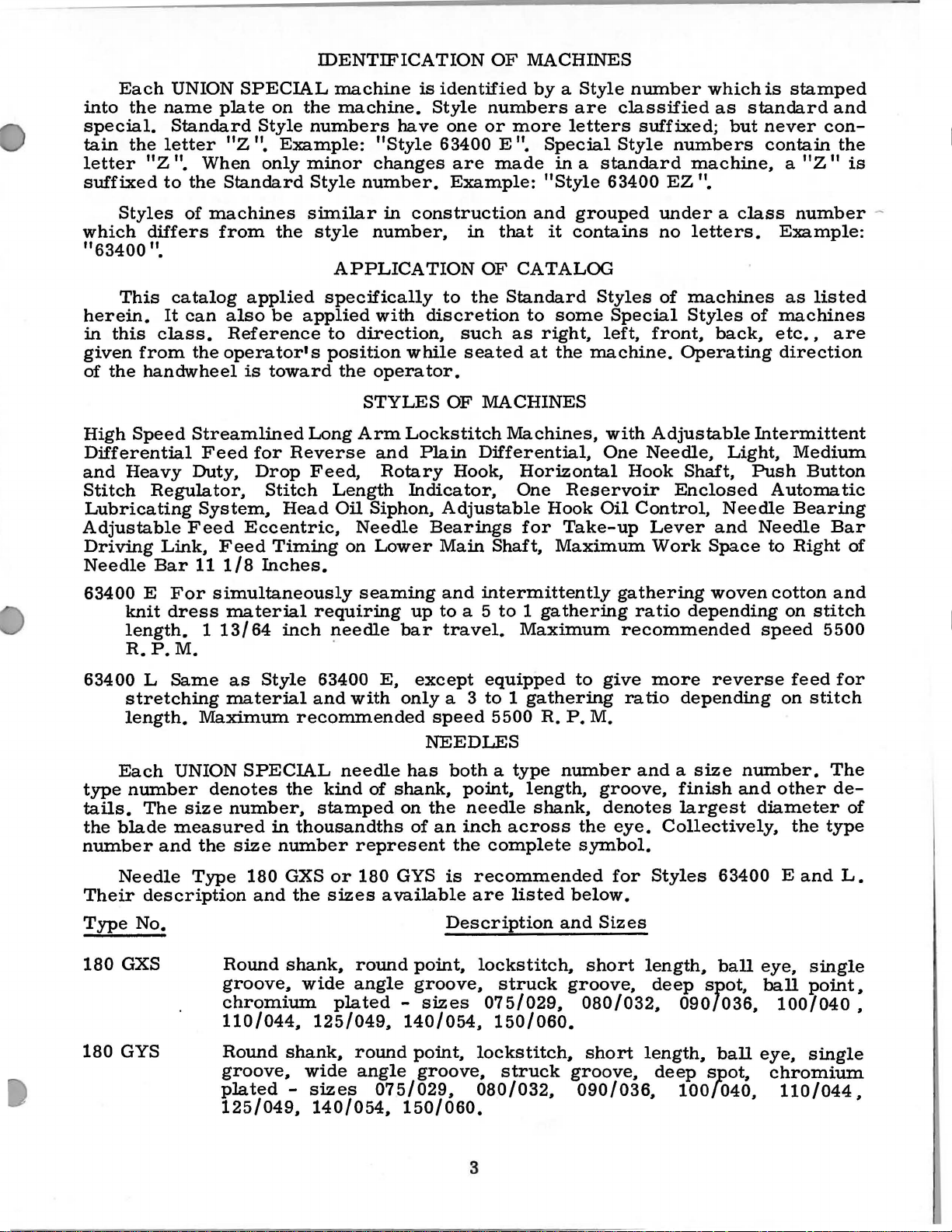
High
It
class.
from
handwheel
Speed
Differential
and
Heavy
Stitch
Regulator,
Lubricating
Adjustable
Driving
Needle
Link,
Bar
UNION
SPECIAL
plate
Standard
•
When
the
Standard
of
machines
"Z
11
from
catalog
can
also
Reference
the
operator's
Streamlined
Feed
Duty,
System,
Feed
Feed
111/8
on
the
Style
11
•
only
numbers
Example:
minor
Style
similar
the
style
applied
be
applied
is
toward
Long
for
Reverse
Drop
Feed,
Stitch
Head
Eccentric,
Timing
Inches.
machine
machine.
is
Style
have
"Style
changes
number.
in
construction
number,
APPLICATION
specifically
with
to
direction,
position
the
opera
discretion
while
tor.
STYLES
Arm
Lockstitch
and
Plain
Rotary
Length
Oil
Needle
on
Indicator,
Siphon,
Bearings
Lower
identified
numbers
one
or
more
63400
are
E ".
made
Example:
in
that
OF
CATALOG
to
the
Standard
such
as
seated
OF
MACHINES
Machines,
Differential,
Hook,
One
Adjustable
Main
Shaft,
by a Style
are
letters
Special
in a standard
"Style
and
grouped
it
contains
Styles
to
some
right,
at
the
machine.
Horizontal
Reservoir
Hook
for
Oil
Take-up
Maximum
number
classified
suffixed;
Style
63400
under a class
no
of
Special
left,
One
with
front,
Adjustable
Needle,
Hook
Control,
Lever
Work
which
as
numbers
machine,
EZ
".
letters.
machines
Styles
back,
Operating
Shaft,
Enclosed
Needle
and
Space
is
stamped
standard
but
never
contain
a
Example:
as
of
machines
etc.,
direction
Intermittent
Light,
Push
Automatic
Needle
to
and
con-
the
11
"Z
is
number
listed
are
Medium
Button
Bearing
Bar
Right
of
-
63400 E For
knit
dress
length. 1 13/64
R.P.M.
63400 L Same
stretching
length.
Each
type
number
tails.
the
blade
number
Needle
Their
Type
180
No.
GXS
The
description
Maximum
UNION
size
measured
and
the
Type
simultaneously
material
requiring
inch
as
Style
material
63400
and
recommended
SPECIAL
denotes
number,
size
Round
groove,
180
and
the
stamped
in
thousandths
number
GXS
the
shank,
wide
chromium
110/044,
125/049,
seaming
needle
.
with
needle
kind
represent
or
180
sizes
round
angle
plated
up
bar
E,
except
only
has
of
shank,
on
of
GYS
available
point,
groove,
-
sizes
140/054,
and
intermittently
to
a 5
to 1 gathering
travel.
equipped
a 3
to 1 gathering
speed
5500
NEEDLES
both a type
point,
the
needle
an
inch
the
complete
is
recommended
are
Description
lockstitch,
struck
075/029, 080/032, 090/036,
150/060.
Maximum
R.
P.M.
number
length,
shank,
across
listed
and
groove,
gathering
to
give
groove,
denotes
the
eye.
symbol.
for
below.
Sizes
short
woven
ratio
depending
recommended
more
ratio
reverse
depending
and a size
finish
largest
Collectively,
Styles
length,
deep
63400 E and
ball
spot,
cotton
on
speed
feed
on
number.
and
other
diameter
the
eye,
ball
100/040,
and
stitch
5500
for
stitch
The
de-
of
type
L.
single
point,
180
GYS
I
Round
groove,
plated
125/049,
shank,
wide
-
sizes
140/054,
round
angle
075/029,
point,
groove,
150/060.
lockstitch,
struck
080/032,
3
short
groove,
090/036,
length,
deep
100/040,
ball
spot,
eye,
single
chromium
110/044,
Page 4
To
have
sample
on
label. A complete
needle
needle,
or
orders
the
type
order
NEEDLES
promptly
and
size
would
read:
(Continued)
and
accurately
number
"1000
should
Needles,
filled,
be
forwarded.
Type
an
180
empty
GXS,
package,
Use
Size
a
description
080/032".
Selection
used.
stitch
Thread
formation.
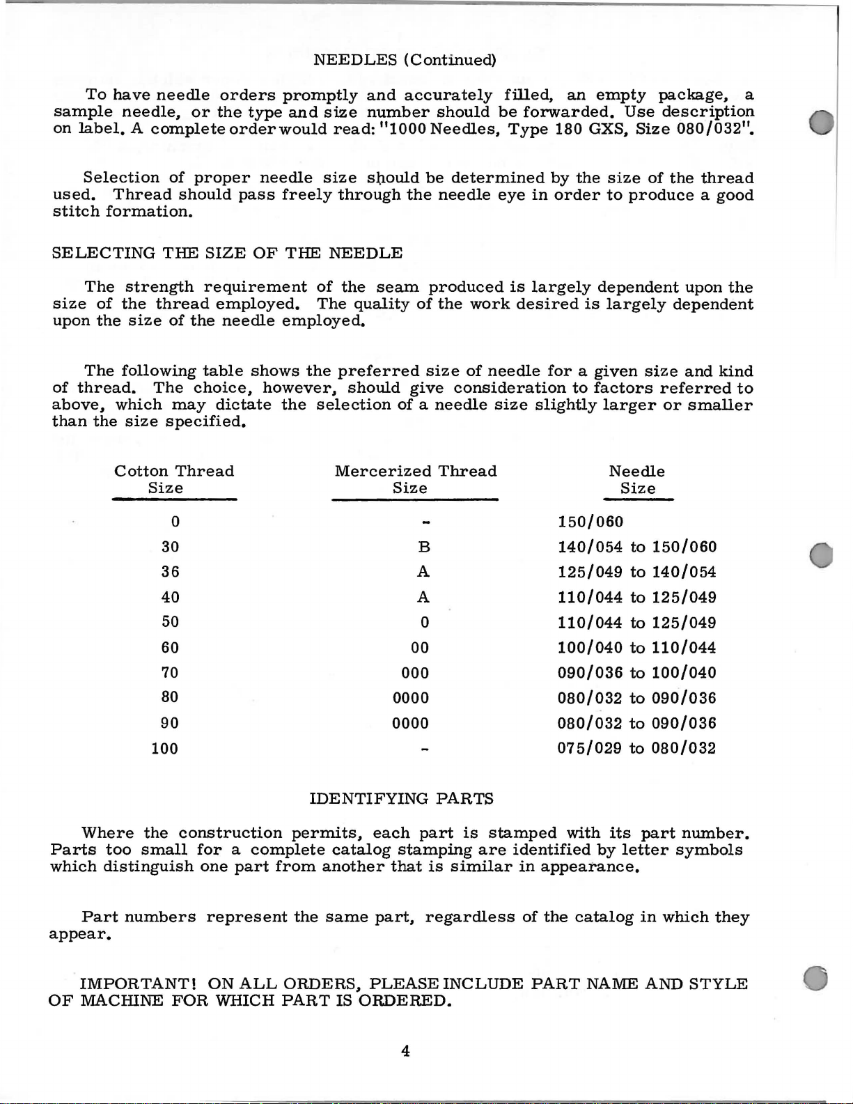
SELECTING
The
strength
size
upon
of
above,
than
of
the
the
The
following
thread.
which
the
size
size
Cotton
of
proper
should
THE
thread
of
the
The
choice,
may
specified.
Thread
Size
0
30
36
needle
pass
SIZE
freely
OF
requirement
employed.
needle
table
employed.
shows
however,
dictate
the
THE
the
size
sl;lould
through
NEEDLE
of
the
The
quality
preferred
should
selection
Mercerized
be
the
seam
produced
of
size
give
of a needle
Size
B
A
determined
needle
eye
is
the
work
of
needle
consideration
size
Thread
by
in
order
largely
desired
for a given
slightly
150/060
140/054
125/049
the
size
to
dependent
is
largely
to
factors
larger
Needle
of
the
thread
produce a good
upon
the
dependent
size
and
kind
referred
or
smaller
Size
to
150/060
to
140/054
to
Where
Parts
which
too
distinguish
Part
appear.
IMPORTANT!
OF
MACHINE
40
50
60
70
80
90
100
the
construction
small
numbers
FOR
IDENTIFYING
permits,
for a complete
one
part
from
represent
ON
ALL
WHICH
the
ORDERS,
PART
catalog
another
same
PLEASE
IS
ORDERED.
000
0000
0000
each
stamping
that
part,
A
0
00
PARTS
part
is
similar
is
regardless
INCLUDE
stamped
are
identified
in
110/044
110/044
100/040
090/036
080/032
080/032
075/029
with
appearance.
of
the
catalog
PART
to
to
to
to
to
to
to
its
by
letter
NAME
125/049
125/049
110/044
100/040
090/036
090/036
080/032
part
number.
symbols
in
which
AND
they
STYLE
4
Page 5
ILLUSTRATIONS
The
arrangement
Class
plate
position.
being
will
number
63400
Six
replacement
exploded
presents
Small
discussed
be
found a listing
of
pieces
a
view
sector
keyline
fit
in
required
ORDERING
of
this
parts.
plates
of
the
views
the
assembled
of
the
in
catalog
cover
machine,
show
parts
the
particular
OF
REPAIR
is
to
facilitate
the
Standard
parts
by a blackened
machine.
with
their
On
part
view
PARTS
Styles
being
the
being
easy
and
listed
aligned
area
exactly
page
numbers,
shown.
accurate
in
this
as
in
opposite
descriptions
catalog.
their
where
the
ordering
Each
assembled
the
parts
illustration
and
the
of
Numbers
the
position
in
ordering
exploded
view
Sub-assemblies,
bracket
lies,.
tions
30
31
32
33
34
catalog,.
parts
tioned
or a solid
which
under
29126
61437
61438
660-225
88
In
those
no
for
the
in
illustration.
At
the
in
this
book.
the
part
number
in
of
the
parts.
plate
can
the
description
DD
K
B
cases
specific
various
the
description,
back
This
the
first
part
Always
carries
line
be
furnished
Feed
where a part
usage
machines
of
the
will
is
known.
column
in
the
use
a
which
box
on
of
Driving
Feed
Feed
Needle
SetScrew-------------------------------------
will
and,
book
will
facilitate
are
reference
illustration.
the
part
reference
are
sold
the
picture
for
repairs,
the
main
Eccentric
Drive
Drive
Eccentric------------------------------
Eccentric
Bearing
is
common
be
mentioned
are
not
if
necessary,
be
found a numerical
locating
numbers
Reference
number
number
complete,
plate.
are
indicated
numbers
listed
for
each
or
Component
sub-assembly.
and
Connecting
Connecting
--------------------------------
to
all
of
in
the
description.
the
same,
the
illustration
the
the
difference
only,
in
the
part
by
separate
by
indenting
Example:
Rod
Rod
the
machines
specific
index
and
and
merely
should
second
for
never
column.
sale.
part,
parts
of
sub-assemb-
their
Assembly------
----------------
covered
However,
will
of
usage
all
be
the
will
shown
description
are
descrip-
when
be
parts
when
indicate
be
used
Each
in
by
this
the
men-
in
the
shown
only
a
1
1
1
1
1
USE
Success
UNION
ration,
to
the
SPECIAL
its
most
Maximum
Genuine
pair
parts
trademark
in
the
Needles
subsidiaries
approved
efficiency
needles
are
stamped
is
your
GENUINE
operation
and
and
scientific
and
durability
are
packaged
with
guarantee
NEEDLES
of
these
Repair
Parts
authorized
principles,
are
with
the
Union
of
the
highest
AND
machines
as
furnished
distributors.
and
assured.
labels
marked
Special
quality
REPAIR
can
are
trademark,
in
TERMS
ments
unless
Prices
are
otherwise
are
strictly
forwarded
directed.
f.
o.
net
b.
A
cash
and
shipping
charge
subject
point.
is
made
5
to
change
Parcel
to
cover
PARTS
be
secured
by
the
They
made
are
with
~.
materials
without
Post
shipments
the
postage
only
Union
designed
utmost
U S
and
notice.
with
genuine
Special
Corpo-
according
precision.
Genuine
Emblem.
Each
workmanship.
All
ship-
are
insured
and
insurance.
re-
Page 6
CAUTION!
Using
After
be
PREPARATION
extra
is
eyelet
STANDARD
winder
assembly
machine
TABLE
FLUSH
MACHINE MOUNTING
hinge
securely.
and
and
between
to
of
both
Before
the
machine
followed:
A
bag
bobbin,
packed
Insert
(A,
Included
assembly,
rest
TOPS
Lockstitch
with
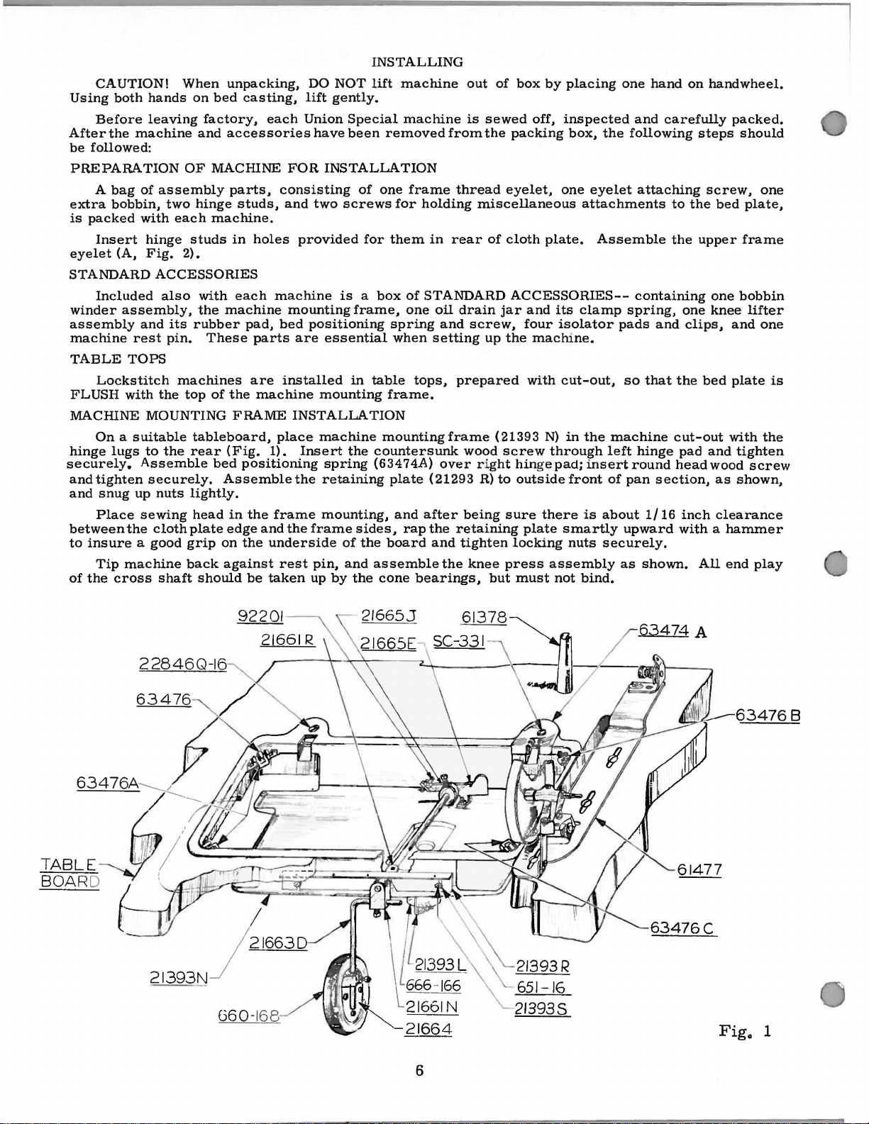
On a suitable
lugs
tighten
snug
up
Place
the
insure a good
Tip
machine
the
cross
When
hands
leaving
of
with
hinge
Fig.
and
to
Assemble
securely.
sewing
on
factory,
and
OF
MACHINE
assembly
two
hinge
each
machine.
studs
2).
ACCESSORIES
also
with
the
its
rubber
pin.
These
machines
the
top
of
tableboard,
the
rear
bed
nuts
lightly.
head
cloth
plate
grip
back
shaft
should
unpacking,
bed
casting,
each
accessories
parts,
studs,
in
holes
each
machine
the
FRAME
(Fig.
Assemblethe
in
edge
on
against
machine
pad,
parts
are
machine
1).
positioning
the
frame
and
the
underside
be
taken
DO
NOT
lift
gently.
Union
FOR
consisting
and
provided
mounting
bed
are
installed
INSTALLATION
place
Insert
the
rest
Special
have
been
INSTALLATION
of
two
screws
for
is a box
frame,
positioning
essential
in
mounting
machine
the
spring
retaining
mounting,
frame
up
pin,
by
sides,
of
and
the
the
INSTALLING
lift
machine
machine
removed
one
for
them
spring
when
table
frame.
mounting
countersunk
(63474A)
plate
and
rap
board
assemblethe
cone
from
frame
holding
in
rear
of
STANDARD
one
oil
and
setting
tops,
frame
over
(21293
after
the
and
bearings,
out
of
is
sewed
the
packing
thread
drain
prepared
retaining
tighten
eyelet,
miscellaneous
of
cloth
ACCESSORIES--
jar
screw,
up
the
(21393
wood
screw
r i
ght
R)
to
being
sure
locking
knee
press
but
box
by
placing
off,
inspected
box,
one
plate.
and
its
four
isolator
machine.
with
cut-out,
N)
in
through
hingepad;insertround
outside
plate
must
front
there
smartly
nuts
assembly
not
one
and
the
following
eyelet
attachments
clamp
the
is
bind.
attaching
Assemble
containing
spring,
pads
so
machine
left
hinge
of
pan
about
upward
securely.
as
hand
on
carefully
to
the
the
one
and
clips,
that
the
cut-out
pad
head
section,
1/16
inch
with a hammer
shown.
handwheel.
packed.
steps
should
screw,
bed
plate,
upper
All
frame
one
bobbin
knee
and
bed
plate
with
and
tighten
wood
as
shown,
clearance
end
lifter
screw
one
one
is
the
play
TABLE
BOARD
22846Q-16
63476
21393N
J
660
I
21663D
-168
63474
A
6
Page 7
INSTALLING
(Continued)
MACHINE
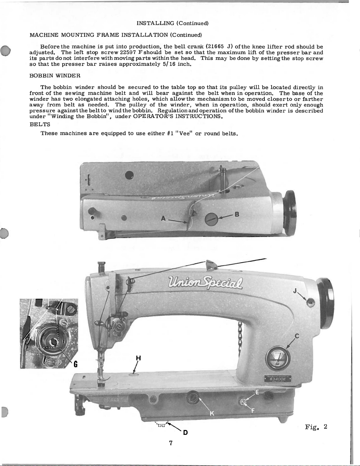
Before
adjusted.
its
parts
so
that
the
BOBBIN
The
bobbin
front
of
winder
away
pressure
under
BELTS
the
has
from
"Winding
These
MOUNTING
the
machine
The
do
WINDER
left
not
interfere
presser
winder
sewing
two
elongated
belt
against
machines
as
the
the
FRAME
is
stop
bar
Bobbin",
put
screw
with
raises
should
machine
attaching
needed.
belt
to
are
equipped
INSTALLATION
into
production,
22597 F should
moving
be
belt
The
wind
under
parts
approximately
secured
and
holes,
pulley
the
bobbin.
OPERATOR1S
to
use
will
of
either
(Continued)
the
be
within
the
5/16
to
the
table
bear
which
allow
the
winder,
Regulation
#1
bell
crank
set
so
head.
inch.
top
against
the
INSTRUCTIONS.
"Vee"
that
This
so
the
mechanism
when
and
operation
or
round
(21665
the
that
belt
J)
maximum
may
its
when
in
operation,
of
belts.
of
the
be
pulley
lift
done
in
operation.
to
be
moved
the
bobbin winder
knee
of
by
will
should
lifter
the
setting
be
located
closer
exert
rod
presser
the
The
to
only
is
should
bar
stop
screw
directly
base
of
or
farther
enough
described
be
and
in
the
7
Fig.
2
Page 8
LUBRICATION
CAUTION 1
the
reservoir
and
run
speed
Lubricate
slowly
operation
must
machine
for
RECOMMENDED
Use a stainless
to
125
Special
check
marked
It
an
extended
oil
the
place
Oil
OIL
GAUGE
The
Should
seconds
specification
oil
level
"full".
is
recommended
bearings
end
may
oil
an
at
at
period,
cover
be
gauge
adjustment
Oil
has
been
be
filled
thoroughly,
can
several
then
minutes
be
OIL
~ater-white
100
Fahrenheit
No.175.
gauge
Oil
(C);
should
be
that a new
be
lubricated
of
the
needle
as
no
further
drained
is
set
from
at
the
become
drained
before
starting
in
to
expected
straight
in
Fill
main
oil
is a maximum
added
machine,
as
bar
link,
hand
main
oiling
reservoir
factory
necessary,
from
the
to
accordance
distribute
without
mineral
the
main
reservoir
when
needle
follows:
take-up
will
to
show
the
main
operate.
the
damage.
reservoir.
level
is
or
one
Remove
and
be
required.
by
removing
the
proper
following
reservoir
with
instructions
oil
to
oil
of a Saybolt
at
plug
when
in
yellow
that
has
the
its
lever
oil
steps
before
the
This
screw
needle
band
been
end
and
plug
level
shipment
which
various
parts.
viscosity
equivalent
(B,
Fig.
is
in
yellow
marked
out
of
service
cover
and
needle
screw
should
in
(D,
the
be
and
follow,
Full
of
to
Union
2)
and
band
"low".
for
directly
bar.
Fig.
Re-
2).
reservoir.
followed:
90
1.
2.
3.
4.
5.
Place
the
Remove
bottom
Oil
should
below
the
Loosen
left
or
on
gauge
Tighten
machine
the
of
the
be
bottom
the
lock
right
(C
..
lock
Fig.
upright
reservoir
machine).
added
edge
nut
(E,
so
that
Fig.
nut
2).
and
3
plug
or
removed
of
the
Fig.
the
gauge
replace
on a level
screw
so
hole.
2)
on
the
needle
plug
screw.
cloth
through
is
tubular.
sprocket
plate
cover
reservoir
ment
very
the
servoir
point
with
just
table
or
(located
that
the
calibrating
rests
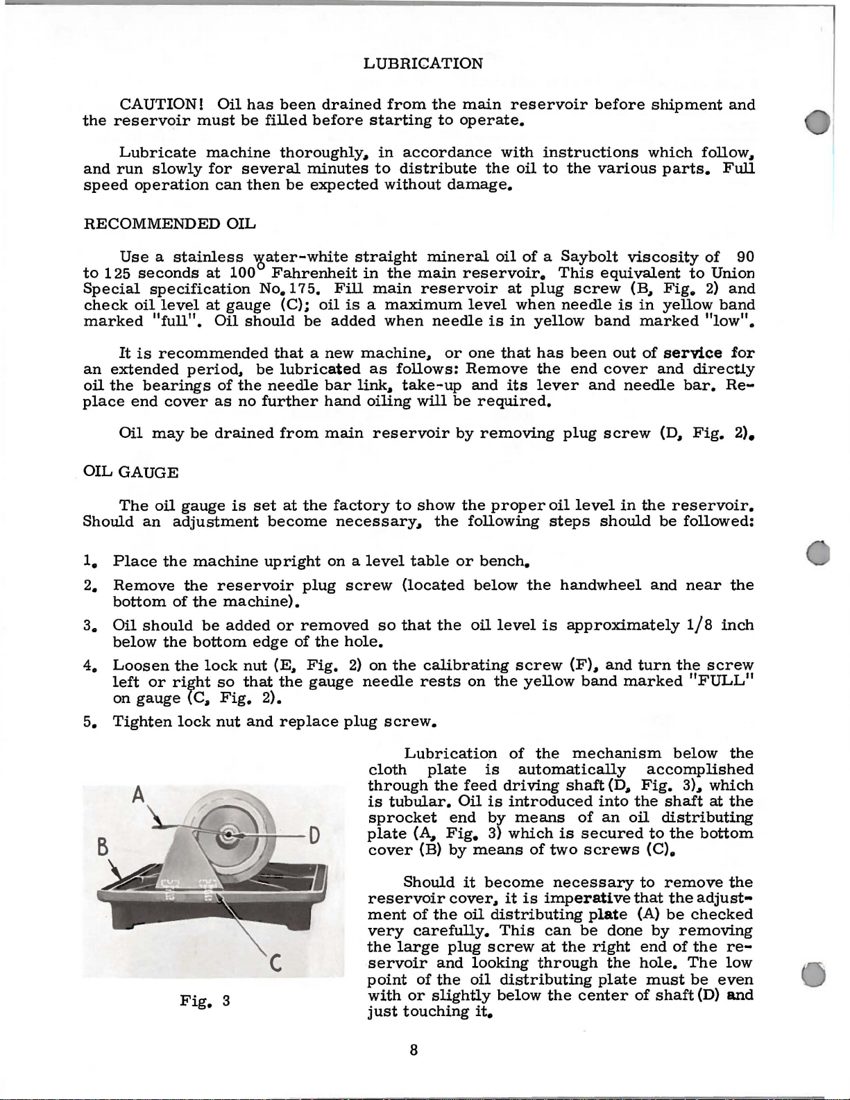
Lubricatiop
plate
the
feed
Oil
end
(A,
Fig.
(B)
by
Should
it
cover,
of
the
oil
carefully.
large
plug
and
of
the
or
slightly
touching
bench.
below
oil
level
screw
on
the
of
is
automatically
driving
is
introduced
by
means
3)
which
means
become
it
distributing
This
screw
looking
oil
distributing
below
it.
the
handwheel
is
approximately
(F),
yellow
the
shaft
is
of
two
necessary
is
imperative
can
at
the
through
the
and
turn
band
marked
mechanism
(D,
Fig.
into
the
of
an
oil
secured
screws
to
that
plate
be
right
center
done
the
plate
(A)
end
hole.
must
of
and
near
1/8
the
the
inch
screw
"FULL"
below
the
accomplished
3),
which
shaft
at
the
distributing
to
the
bottom
(C).
remove
the
be
by
removing
of
shaft
The
the
adjust-
checked
the
re-
low
be
even
(D)
and
8
Page 9
THREAD
INSTRUCTIONS
FOR
OPERA
TORS
While
ofthe
the
of
unwind,
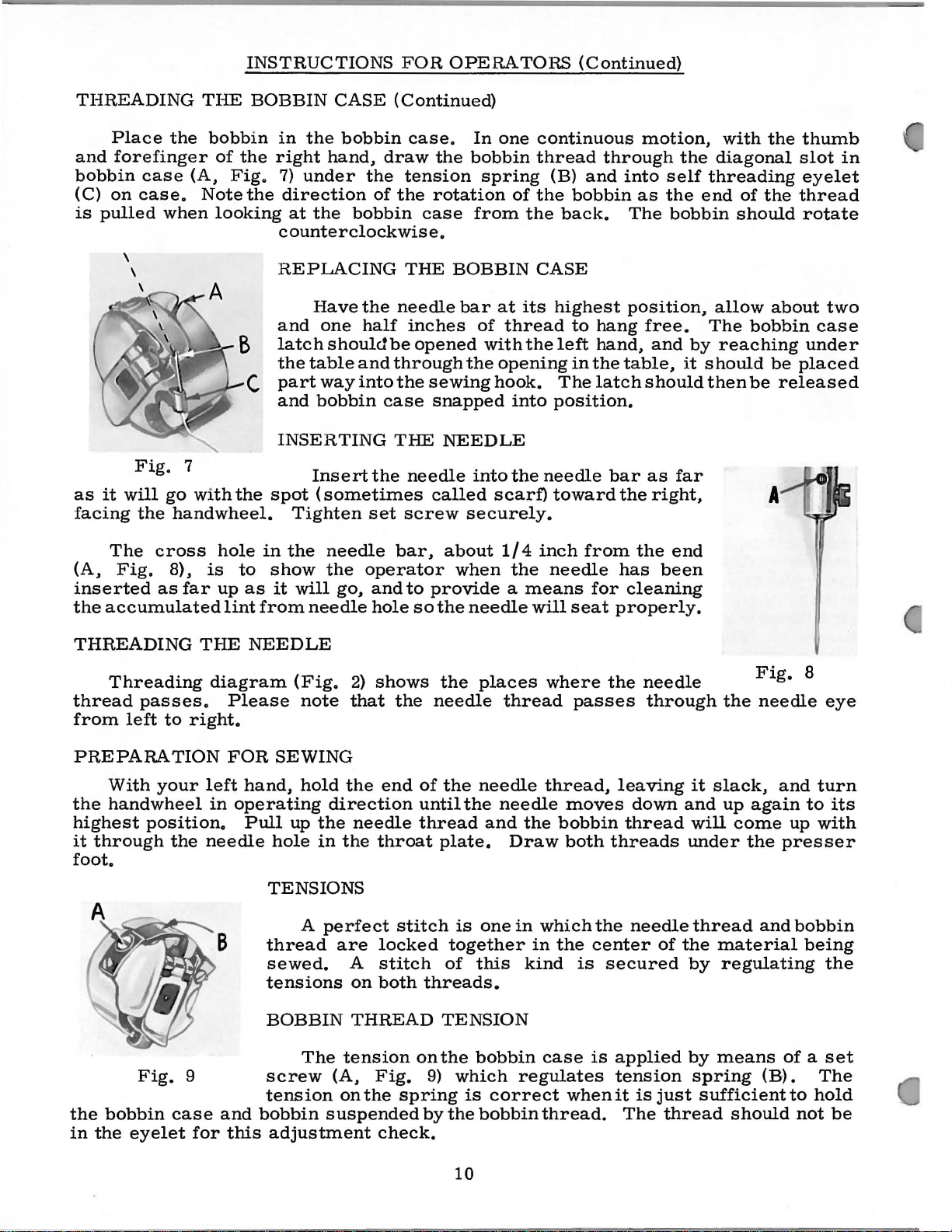
WINDING
from
down
post.
up
a
wardly
contact
position.
will
automatic
pulley.
varied
direction
each
Thread
the
between
to
the
few
turns
be
hook
hand.
Fig.
Press
on
rotated
by
the
direction
rotation
of
twist,
Turn
it
is a left
4
THE
supply
stop,
with
The
regulating
BOBBIN
the
bobbin
down
the
tension
an
empty
wind
in a clockwise
hand
When
throw-out
lever
machine
the
and
extent
of
favors
grasp a short
the
thread
twist,
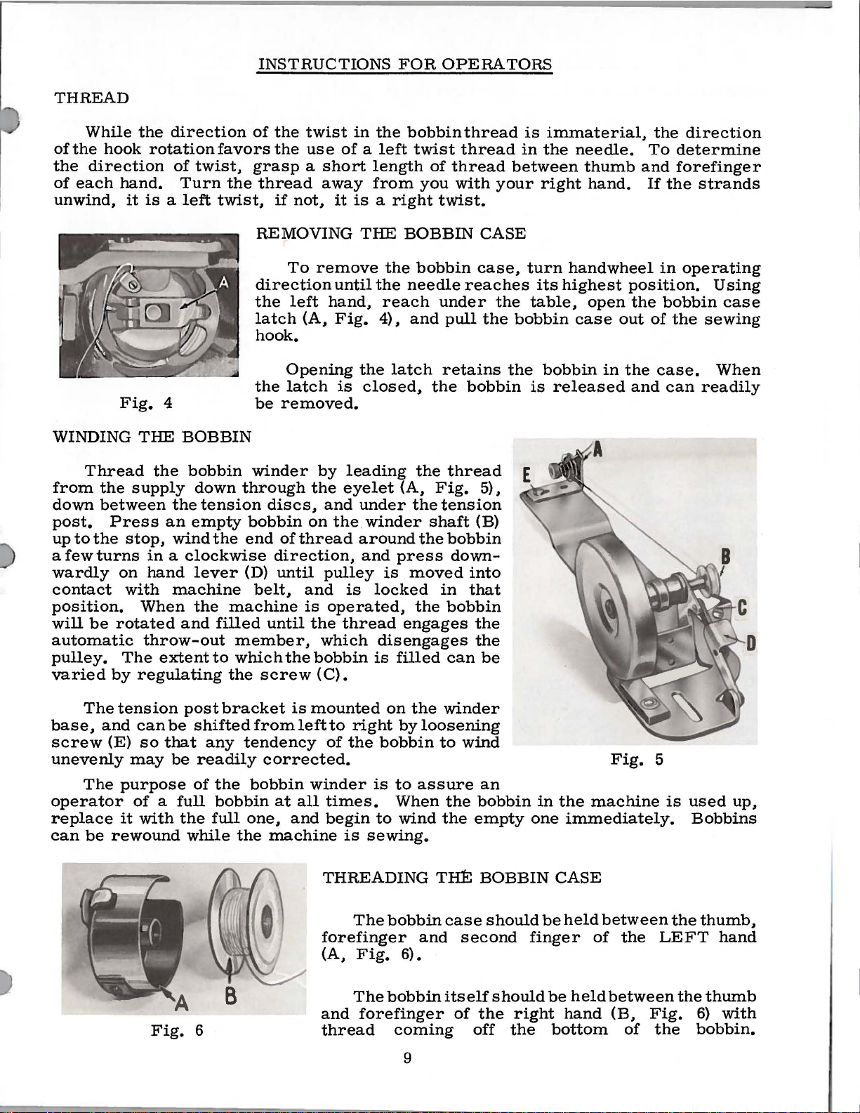
REMOVING
direction
the
latch
hook.
the
be
winder
through
discs,
bobbin
the
end
(D)
belt,
machine
filled
to
until
member,
which
the
screw
the
twist
the
use
away
if
not,
it
To
remove
until
left
hand,
(A,
Fig.
Opening
latch
removed.
of
direction,
until
the
is
by
the
and
on
the. winder
thread
pulley
and
is
operated,
the
which
bobbin
(C).
in
the
of a left
length
from
is a right
THE
the
the
reach
4),
the
latch
closed,
leading
eyelet
under
around
and
press
is
is
locked
thread
disengages
is
filled
bobbin
twist
of
thread
you
tWist.
BOBBIN
bobbin
needle
under
and
pull
retains
the
the
thread
(A,
Fig.
the
tension
shaft
the
bobbin
down-
moved
in
the
bobbin
engages
can
thread
thread
with
CASE
case,
reaches
the
bobbin
5),
(B)
into
that
the
the
be
is
in
between
your
turn
the
table,
bobbin
the
is
immaterial,
the
needle.
thumb
right
its
bobbin
hand.
handwheel
highest
open
case
released
position.
the
out
in
the
and
the
To
and
If
in
bobbin
of
case.
the
the
can
direction
determine
forefinger
strands
operating
Using
case
sewing
When
readily
The
base,
screw
unevenly
operator
replace
can
and
(E)
The
be
rewound
tension
can
so
may
purpose
of a full
it
with
be
that
be
Fig.
post
shifted
any
readily
of
the
while
6
bracket
from
tendency
the
bobbin
bobbin
full
one,
the
is
mounted
leftto
of
corrected.
winder
at
all
times.
and
begin
machine
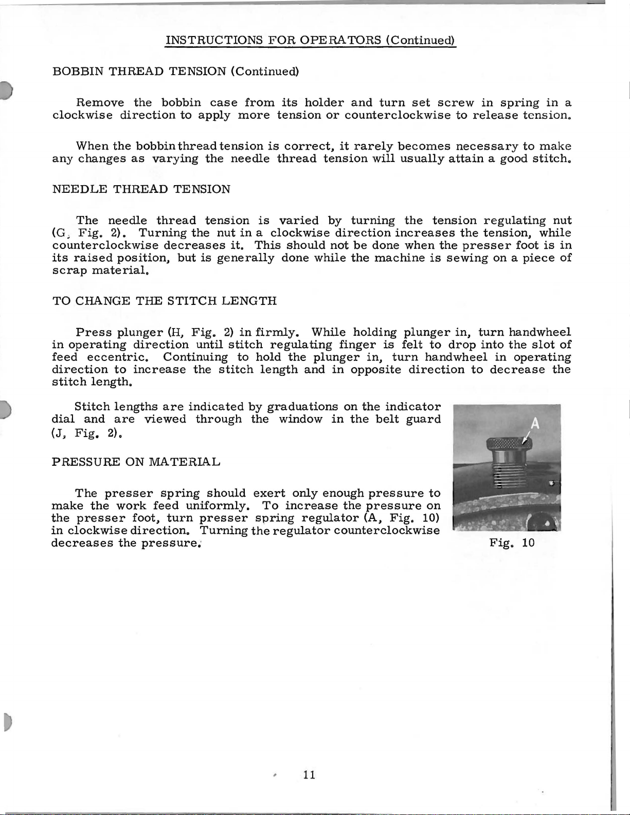
THREADING
forefinger
(A,
and
thread
on
right
the
bobbin
is
to
When
to
is
sewing.
The
bobbin
Fig.
The
bobbin
forefinger
coming
the
by
loosening
assure
wind
Tim
and
6).
9
winder
to
wind
the
bobbin
the
empty
BOBBIN
case
second
itself
of
the
off
an
should
should
in
one
finger
right
the
the
machine
immediately.
CASE
be
held
between
of
be
held
between
hand
botto:r:p.
Fig.
the
(B,
of
5
is
the
LEFT
Fig.
the
used
Bobbins
thumb,
hand
the
thumb
6)
bobbin.
up,
with
Page 10
INSTRUCTIONS
FOR
OPERA
TORS
(Continued)
THREADING
Place
and
forefinger
bobbin
(C)
on
is
pulled
as
it
facing
The
(A,
Fig.
inserted
the
accumulated
case
case.
Fig.
will
the
the
when
go
handwheel.
cross
8),
as
THE
(A,
Note
7
with
far
BOBBIN
bobbin
of
the
Fig.
the
looking
C
the
hole
is
to
up
as
lint
CASE
in
the
bobbin
right
7)
counterclockwise.
REPLACING
and
latch
the
part
and
INSERTING
spot
in
show
it
from
hand,
under
direction
at
the
Have
one
should
table
way
bobbin
Insert
(sometimes
Tighten
the
needle
the
will
go,
needle
the
of
bobbin
the
half
and
into
the
set
operator
and
hole
(Continued)
case.
draw
tension
the
case
THE
needle
inches
be
opened
through
the
case
THE
needle
screw
bar,
to
so
In
the
bobbin
rotation
from
BOBBIN
bar
the
sewing
snapped
NEEDLE
into
called
securely.
about
when
provide a means
the
needle
one
spring
of
at
of
thread
with
opening
hook.
into
the
scarf)
1/4
the
continuous
thread
(B)
and
the
bobbin
the
back.
CASE
its
highest
to
the
left
in
The
position.
needle
toward
inch
from
needle
for
will
seat
through
into
as
The
position,
hang
hand,
the
table,
latch
bar
the
the
has
cleaning
properly.
motion,
the
self
the
bobbin
free.
and
by
it
should
as
far
right,
end
been
with
diagonal
threading
end
of
should
allow
The
bobbin
reaching
should
then
be
the
thumb
slot
eyelet
the
thread
rotate
about
under
be
placed
released
A
in
two
case
THREADING
Threading
thread
from
PREPARATION
the
highest
it
through
foot.
the
in
passes.
left
With
handwheel
bobbin
the
your
position.
Fig.
eyelet
to
the
case
right.
9
for
THE
diagram
Please
FOR
left
hand,
in
operating
Pull
needle
B
and
this
NEEDLE
(Fig.
note
SEWING
hold
up
the
hole
TENSIONS
thread
sewed.
tensions
BOBBIN
screw
tension
bobbin
adjustment
in
A
The
2)
shows
that
the
the
end
direction
needle
the
throat
perfect
are
tension
(A,
on
suspended
stitch
locked
A
stitch
on
both
THREAD
Fig.
the
check.
the
needle
of
until
thread
plate.
threads.
TENSION
on
the
9)
spring
by
places
the
needle
the
and
is
one
together
of
this
bobbin
which
is
correct
the
bobbin
where
thread
thread,
needle
the
Draw
in
which
in
kind
case
regulates
thread.
passes
moves
bobbin
both
the
the
center
is
is
when
the
needle
through
leaving
down
thread
threads
needle
of
secured
applied
tension
it
is
just
The
it
and
will
under
thread
the
by
by
spring
sufficient
thread
Fig.
the
needle
slack,
up
material
regulating
means
should
and
again
come
the
and
(B).
8
eye
turn
to
its
up
with
presser
bobbin
being
the
of a set
The
to
hold
not
be
10
Page 11
INSTRUCTIONS
FOR
OPERA
TORS
(Continued)
BOBBIN
Remove
clockwise
When
any
NEEDLE
The
(G,
THREAD
the
changes
THREAD
needle
Fig.
2).
the
direction
bobbin
as
Turning
counterclockwise
its
raised
scrap
TO
CHANGE
Press
in
operating
feed
direction
stitch
position,
material.
THE
plunger
direction
eccentric.
to
increase
length.
TENSION
bobbin
to
thread
varying
TENSION
thread
the
decreases
but
STITCH
(H,
Fig.
until
Continuing
the
case
apply
tension
the
tension
nut
is
generally
LENGTH
2)
stitch
(Continued)
from
more
needle
is
is
its
tension
correct,
thread
varied
in a clockwise
it.
This
should
done
in
firmly.
stitch
to
regulating
hold
the
length
holder
or
tension
by
not
while
While
plunger
and
in
and
turn
set
counterclockwise
it
rarely
turning
direction
be
the
holding
finger
in,
opposite
becomes
will
usually
the
increases
done
when
machine
plunger
is
felt
turn
direction
screw
to
release
necessary
attain a good
tension
the
the
presser
is
sewing
in,
to
drop
handwheel
to
in
spring
regulating
tension,
foot
on a piece
turn
handwheel
into
the
in
operating
decrease
in
tension.
to
make
stitch.
nut
while
is
in
of
slot
of
the
a
Stitch
dial
(J~
and
Fig.
2).
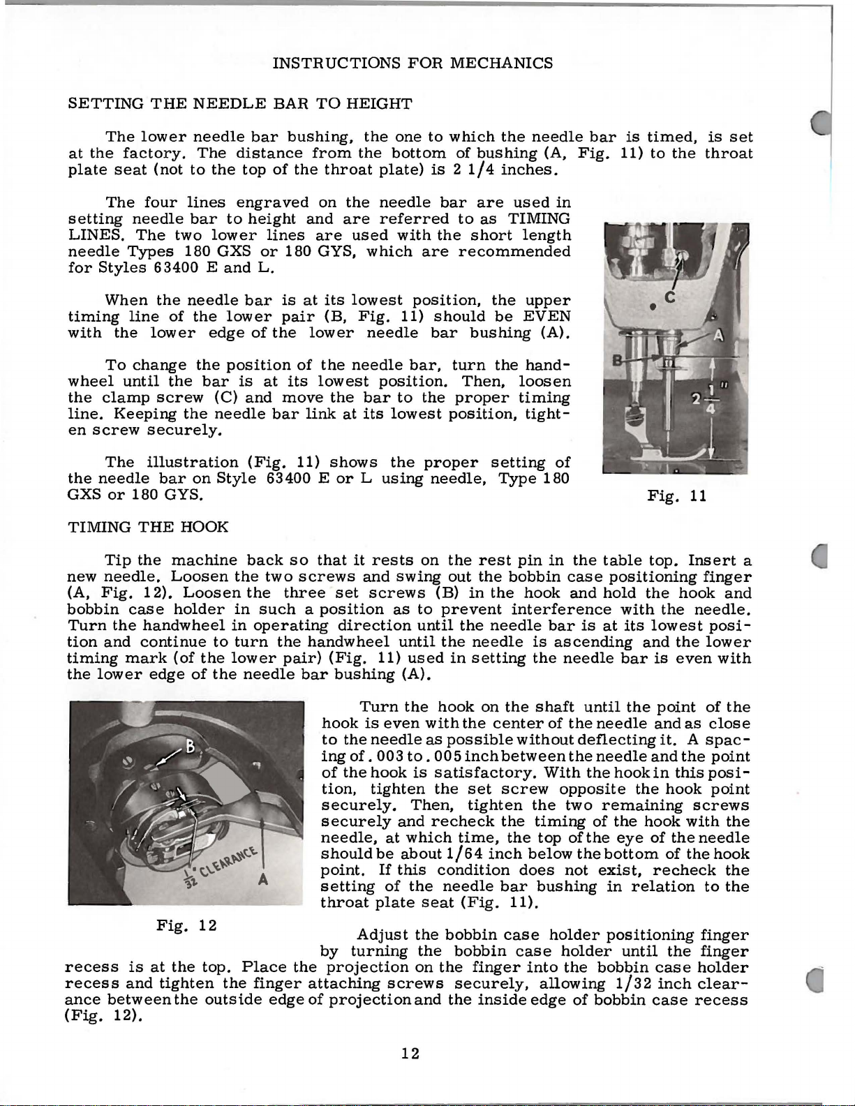
PRESSURE
The
presser
make
the
in
the
presser
clockwise
decreases
lengths
are
viewed
ON
work
foot,
direction.
the
pressure.
are
indicated
through
MATERIAL
spring
feed
turn
should
uniformly.
presser
Turning
·
by
graduations
the
window
exert
To
increase
spring
the
regulator
only
enough
regulator
on
the
indicator
in
the
belt
guard
pressure
the
pressure
(A,
Fig.
counterclockwise
to
on
10)
Fig.
10
11
;
Page 12
INSTRUCTIONS
FOR
MECHANICS
SETTING
The
at
the
factory.
plate
setting
LINES.
needle
for
timing
with
wheel
the
line.
en
the
GXS
seat
The
Types
Styles
When
the
To
until
clamp
Keeping
screw
The
needle
or
line
180
THE
lower
four
needle
The
lower
change
securely.
illustration
NEEDLE
needle
The
(not
to
lines
bar
two
180 GXS
63400 E and
the
needle
of
the
the
the
screw
the
bar
on
GYS.
the
to
lower
lower
edge
position
bar
(C)
needle
Style
BAR
bar
bushing,
distance
top
of
the
engraved
height
lines
or
180 GYS,
L.
bar
is
pair
of
the
is
at
its
and
move
bar
(Fig.
63400 E
TO
from
and
are
at
lower
of
lowest
link
11)
throat
on
its
(B,
the
the
shows
HEIGHT
the
one
the
bottom
plate)
the
needle
are
referred
used
lowest
needle
at
or L using
which
Fig.
needle
position.
bar
its
lowest
the
with
position,
11)
bar,
to
to
which
of
bushing
is 2 1/4
bar
are
to
the
short
are
recommended
should
bar
bushing
turn
Then,
the
proper
position,
proper
needle,
the
inches.
as
TIMING
the
be
the
setting
Type
needle
(A,
used
length
upper
EVEN
(A).
handloosen
timing
tight-
180
in
of
bar
Fig.
is
11)
timed,
to
the
Fig.
is
throat
11
set
TIMING
Tip
new
needle.
(A,
Fig.
bobbin
Turn
tion
timing
the
recess
recess
ance
(Fig.
the
and
lower
between
12).
THE
the
machine
Loosen
12).
case
mark
is
and
holder
handwheel
continue
(of
edge
Fig.
at
the
tighten
the
HOOK
Loosen
to
the
of
the
12
top.
outside
back
the
the
in
in
turn
lower
needle
Place
the
so
two
three
such a position
operating
the
pair)
the
finger
edge
that
it
screws
set
direction
handwheel
(Fig.
bar
bushing
Turn
hook
to
the
ing
of.
of
the
tion,
securely.
securely
needle,
should
point.
setting
throat
Adjust
by
turning
projection
attaching
of
projection
rests
and
swing
screws
as
until
11)
is
even
needle
003
hook
tighten
and
at
be
If
this
of
plate
screws
on
the
out
(B)
to
prevent
until
the
used
(A).
the
hook
with
as
possible
to.
005
is
satisfactory.
the
Then,
recheck
which
about
condition
the
seat
the
the
on
the
and
1/64
needle
bobbin
the
rest
the
in
the
the
needle
needle
in
setting
on
the
center
inch
between
set
screw
tighten
the
time,
inch
bar
(Fig.
case
bobbin
finger
securely,
inside
pin
in
the
bobbin
hook
interference
the
without
the
does
11).
case
case
and
bar
is
ascending
the
needle
shaft
of
the
the
With
opposite
the
two
timing
top
of
below
not
bushing
holder
holder
into
the
allowing
edge
deflecting
the
of
table
positioning
hold
with
is
at
its
bar
until
the
needle
needle
the
hook
remaining
of
the
the
eye
bottom
exist,
in
positioning
until
bobbin
1/32
bobbin
top.
the
hook
the
lowest
and
the
is
even
point
and
it. A spac-
and
in
this
the
hook
hook
of
the
of
recheck
relation
the
case
inch
case
Insert
finger
needle.
posi-
lower
of
as
close
the
point
posi-
point
screws
with
needle
the
to
finger
finger
holder
clear-
recess
a
and
with
the
the
hook
the
the
12
Page 13

INSTRUCTIONS
FOR
MECHANICS
(Continued)
In
(B,
Fig.
The
in
contact
toward
is
at
bottom
time,
there
For
of
size • 048
guarding
Before
related
1.
See
2.
Check
3.
Rotate
Check
cited
the
hook,
13)
is
purpose
with
the
hook
of
should
additional
and
su~face
metal
settings
that
the
for
handwheel
for
above
NEEDLE
at
GUARD
the
found a needle
of
this
guarding
the
needle
point.
its
The
vertical
be
little
needle
larger
may
needles,
be
necessary.
removal
should
be
needle
proper
hook
in
excessive
needle
as a desirable
INSTRUCTIONS
right
side
guarding
surface
(D)
at
needle
travel.
or
clearance,
removal
from
the
checked
bar
is
timing.
operating
deflection
condition.
of
the
surface
is
to
loop-taking
guard
no
will
if
the
deflection
especially
of
guarding
as
follows:
set
to
correct
direction
beyond
needle
prevent
time,
deflect
hook
some
surface.
by
FOR
(A,
is
properly
of
with
needle
height.
hand.
what
hole
Fig.
the
should
the
needle
use
all
is
NO.
in
13).
hook
needle
29474
the
bobbin
point
the
needle
slightly.
timed.
by
the
P
(C)
(At
needle
Fig.
case
from
be
when
holder
coming
deflected
needle
loop-taking
guard.)
13
4.
If
needle
(
1)
Remove
(
2)
Remove
using a 1/8
bench
is
the
needle
CAUTION!
needle
hook
guarding
The
base.
bobbin
When
REMOVED
Bobbin
pulling
on
slightly.
HOOK
LUBRICATION
CAUTION!
damage
may
deflection
bobbin
excess
and
removed.
bobbin
guarding
Damage
surface.
case
altering
or
disturbed
case
holder
bobbin
Do
result.
inch
rubbing
When
case
holder
holder
needle
case
not
is
excessive,
case
metal
strip
the
metal
is
obtained.
to
hook
guarding
from
only
stem
run
the
holder
from
offine
guarding
should
point
should
its
may
be
as
machine
follow
from
needle
emery
is
being
be
may
be
surface.
timed
removed
the
handwheel
steps 1 and 2 below.
hook.
guarding
cloth
surface
removed
re-inserted
result
thoroughly
position.
by
without
surface.
(#320),
back
and
from
frequently
if
too
cleaned
it
is
suggested
removing
is
rocked
the
bobbin
with
forth
needle
much
gib
This
one
end
until
guarding
and
tested
metal
before
is
re-assembly
the
screws
backwards
case
in
the
may
be
done
secured
sufficient
surface,
until
proper
removedfrom
hook
and
gib
and
hook
NOT
forwards
as
to
metal
into
and
hook
by
the
BE
by
With
piece
about
should
of
white
five
be
the
bobbin
paper
seconds,
observed.
case
directly
remove
in
under
the
the
hook,
the
paper
run
the
machine
hook
and
continue
and a definite
and
13
for a full
running
distinct
minute.
the
machine.
pattern
of
Place
oil
a
After
spots
Page 14

INSTRUCTIONS
FOR
MECHANICS
(Continu
ed)
Should
required,
adjusting
cated
chine
on
just
surface,
change
in
should
before
oil
the
flow.
required.
hook
be
checking
SETTING
The
14
should
depth
throat
of
slots
ximum
lower
of a full
plate
travel
of
feed
the
Tighten
backward
more
turn
shaft
the
below
in
the
oil
run
THE
main
be
at
and
the
throat
travel.
main
screw.
settings
or
less
the
oil
(K,
Fig.
front
the
of
the
cloth
direction
After a change
flow,
about
MAIN
feed
the
center
for
set
tooth
the
machine
one
the
FEED
dog
(A,
to
rise
above
highest
in
plate
To
raise
feed
dog,
The
feed
of
the
HOOK
oil
control
2),
lo-
ma-
plate
of
the
minute
desired
DOG
Fi
the
the
point
the
feed
at
rnaloosen
bar
main
LUBRICATION
be
g.
or
screw
has
been
feed
dog
set
are
(Continued)
(B)
and
at
the
factory
established.
set
Fig.
feed
so
14
dog
the
to
specified
lateral.,
height.,
forward
or
plate
Fig.
across
15
the
SETTING
line
of
set
at
of
this
the
screw
at
dog
The
with
ential
(F)
elongated
machine
screws
forward
properly.
the
can
feed.
THE
the
the
DIFFERENTIAL
The
differential
to
rise
highest
throat
the
teeth
top
surface
To
raise
(D)
specified
Loosen
forward,
sides
the
main
feed
and
move
back
(A,
or
differential
be
aligned
Tighten
the
depth
point
plate
of
of
or
and
adjust
height.
feed
backward
of
the
feed
dog
is
feed
slots
against
Fig.
backward
The
loosening
parallel
screws
feed
of a full
of
travel
at
maximum
the
differential
the
throat
lower
feed
Tighten
dog
holding
differential
dog.
required,
dog
of
feed
the
15)
and
as
feed
bar
securely.
FEED
dog
the
dog
or
If
more
so
that
dog.
rest
move
required
of
to
with
sideways
DOG
(C.,
Fig.
tooth
and
plate
center
feed
feed
across
above
travel.
should
differential
holder
screw.
screws
(F)
in
feed
dog
adjustment
first
loosen
screws
Tighten
pin.
Loosen
differential
to
screws
be
the
top
(A)
rotated
surface
14)
should
the
in
the
the
feed
(E)
to
to
space
the
should
holding
are
screws.
position
will
so
throat
feed
In
addition
be
parallel
line
dog
set
feed
the
thr0at
be
of
the
centered
Now
the
fe
ed
feed
also
the
feed
of
the
also
plate
slots
of
feed.
loosen
dog
feed
plate.
in
line
differ-
screws
two
set
bar
(B)
dog
allow
dog
throat
be
to
to
in
tip
14
Page 15

INSTRUCTIONS
FOR
MECHANICS (Continued)
Set
the
rear
(G,
Fig.
clockwise
wise
front
(J)
by
more
lesser
gathering
located
NOTE:
stops
engage
dogs
feed
contact
vel.
63400 E and 3 to 1 on
main
14)
by
for
for
less
intermittent
turning
gather
gathering
ratio
in
the
After
(G
and
the
differential
have
slot
The
feed
clearance
and
each
gathering
dog.
and
bed
J)
other
differential
turning
more
differential.
differential
screw
counterclockwise
ratio.
can
plate.
setting
turn
that
the
at
ratio
DIFFERENTIAL
feed
screw
differential
(K)
be
read
the
machine
to
at
two
the
is 5 to 1 on
Style
(H)
counter-
or
Then
feed
clockwise
The
be
the
back
differential
on
differential
by
hand
sure
front
feeds
end
63400
clock-
set
dial
the
end
do
of
L,
stop
stop
for
feed
feed
tra-
Style
FEED
the
for
a
(L)
and
of
not
depending
ADJUSTMENT
on
the
length
Fig.
of
16
stitch
set
at
the
The
presser
set
so
that
it
guide
back
16),
bell
left,
accomplished.
screw
(B).
against
and
relocating
crank
the
proper
in
place.
This
(C).
PRESSER
bar
is
about
is
accomplished
the
rest
the
By
turning
setting
Tighten
BAR
connection
1/16
pin,
inch
loosening
stop
screw
the
of
the
the
lock
CONNECTION
(A, Fig. 17)
below
by
(B)
stop
presser
nut
tipping
the
lock
on
screw
bar
(A)
the
the
to
to
should
presser
the
machine
nut
(A,
lifter
the
connection
lock
lever
right
the
be
bar
Fig.
or
is
stop
Fig.
17
15
Page 16

INSTRUCTIONS
FOR
MECHANICS
(Continued)
PRESSER
When
directly
set
is
t
he
top
To
l
oosen
plate.
the needle ente
pressure to
P
RESSER
The presser
press
presser
To
follows:
1.
Remove
2.
Insert
3.
Loosen
the
BAR
locating
against
properly
of the
obtain
s et
screw
Set the g
the presser
BAR
er feet.
bar
adapt
presser
the
screw
GUIDE
the
the
throat
wh n there
throat plate
this setting,
(C).
uide to
rs the mi
Howeve
is
adaptable.
the
presser
set
as a handle.
the
bar
machine
foot
foot
screw
presser
is
(Fig.
Tap
4 3 I 4
ddle
foot
No.
r,
should
to
and
screw
in
bar
plate
of
63457 J is
the
with
a 4 3 I 4
17)
remove
on
presser
inch
its
slot
by
turning
feet
receive
presser
in
the
presser
guide
the
inch
the
dimension,
and
presser
presser
(B,
feed
space
pressure
foot
to
retighten
the
regulator
designed
of a different
feet
foot
screw
bar
guide
Fig.
dog
in
between
from
insure
center
screw
primarily
of
from
bar
so
and
17),
the
presser
its
lowest
the
thread
the
presser
its
being
the
foot
(C)
(A,
Fig.
to
manufacture
other
it
rotate
manufacture,
presser
screws
presser
position.
take-up
down
by
turning
in
guide.
10)
clockwise.
receive
be
bar.
in
from
foot
must
The guide
spring
on
the
it
Now,
Union
required,
proceed
right
bar
180°
wire
(F)
throat
so
apply
Special
to
using
r e
st
and
and
that
th
as
left.
e
4.
Attach
the
5.
Check
CAUTION!
the
presser
Test
should
snap
it
located
assembly,
loosen
socket
wise
upper
tension
spring
proceed
desired
the
adjustment
the
be
when
require
tension
(C).
until
stop
post
again
tension
slotted
presser
needle.
the
guide
check
enough
spring
adjusting,
under
and
Turn
the
(E)
(D)
further
tension
post
of
end
foot
presser
When
height
spr
tension
is
arm
remove
post
the
check
and
in a clockwise
touches
in
is
set
the
check
of
bar
presser
TENSION
ing
tension
depressed
loosen
and
tension
set
tension
spring
has
the
the
obtained.
screw
the
to
the
bar
guide
feet
must
screw
no
(B)
spring
tension
be
(A,
to
assure a good
and
set
to
the
assembly.
(B)
post
moves
tension
upper
same
When
should
tension
and
align
for
correct
other
checked
ASSEMBLY
screw
(D)
direction
stop
direction
be
post
than
and
Fig.
18).
returning
released.
in
right
in
on
of
Partially
tension
counterclock-
away
drawn
from
it.
(E).
until
correct
can
be
(D)
the
needle
height
of
Union
reset
ADJUSTMENT
There
Should
the
tension
Turn
until
Then,
1
y
up
made
and
and
Special
where
head
post
the
the
the
the
set,
snugly,
by
turning
hole
or
tighten
manufacture
necessary.
yet
not
inserting
in
the
slot
of
the
set
screw
F"
lg.
18
forcefully.
a
screwdriver
required
foot
securely.
are
E
Further
direction.
with
used,
0
into
Replac.:etension
take-up
should
wire.
be
While
resting
assemblywith
the
tension
on
the
throat
the
post
plate.
check
assembly
spring
16
is
about
being
318
inch
replaced,
above
the
presser
the
thread
foot
Page 17

INSTRUCTIONS
FOR
MECHANICS
(Continued}
TENSION
The
seams
tension
insure a good
is
depressed
is
adjusted
with a postal
RELEASE
tension
or
when the
release
Fig.
19
and
from
release
cam
returning
released.
about 1 to 1 1/4
scale
whenthecheckspringis
The
tension
but
not
release
(D ~ Fig.
located
correct
post
forcefully
pin
should
18}.
just
height
The
below
as
set
tightened
follows:
should
presser
(D ~ Fig. 1 7}
are
when
(A~
the
position
screw.
positioned
raising
the
of
presser
release
THREAD
Check
snap
(C~
Fig.
1/32
screw
move
check
the
spring
tension
be
foot
required
The
in
the
tension
Fig.
flange
The
tension
or
average
cam
Check
spring
when
The
ounces
20}.
to1/16
should
(B~
Fig.
freely
discs~
set
so
that
is
raised
and
the
in
for
proper
and
out
position
discs
19}.
is
Set
the
of
the
tension
maintained.
release
by
loosening
lowering
release
foot
lift
set
screw
CONTROL
the
adjustment
tension.
spring
check
(B~
spring
when
This
is
inchfromitsstop.
be
drawn
18).
in
eyelet
the
The
tension
(A~
should
it
will
for
back
and
out
operation.
are
in
stop
Tighten
cam
set
the
cam
point
above
securely.
of
There
Fig.
tension
measured
measured
up
snugly
tension
post
Fig.
be
set
not
tacking.
position
of
the
tension
line
with
screw
assembly
(D ~ Fig. 1 7)
screw
to
suit
being
the
throat
tension
should
20)
19}
~
for
release
The
of
the
assembly
the
(B~
Fig.
rests
the
tension
(E~
the
between
plate.
assembly
be
C
when
adjustment
tension
check
19}
spring
so
against
assembly
should
Fig.
17)
sewing
1/4
to
Tighten
(A~
enough
sewing
over
of
assembly
is
correct
eyelet
that
when
it~
now
and
then
conditions.
5/16
inch
tension
Fig.
tension
the
this
set
be
20).
to
With a thread
thread
should
(Fig.
dis.cs
19).
so
without
to
thread
Class
63400,
wire
in a straight
be
set
Be
that
1/16
sure
the
obstruction.
machine
Fig.
and
running
from
line,
to
1/8
the
eyelet
check
After
as
spring
per
making
threading
21
as a result,
the
inch
is
will
the
the
tension
check
below
set
close
pass
this
setting~
spring
the
to
freely
post
thread
the
diagram
Sew
slowly
the
action
the
check
taut
when
stroke.
may
tension
Slight
be
necessary
should
consistent
with 3 to 4 ounces
cord
(A,
checking
heavy
or
Fig.
to
similar
the
adjustment,
disc
tension
17
to
eyelet
line
tension
over
proceed
(Fig.
on a piece
of
the
spring
the
take-up
changes
be
stitch.
21}.
tension.
you
when
but
can
be
the
it
2).
check
to
the
at
this
used
The
needle
thread
Depress
The
compared
this
is a required
reduced.
Fig.
of
material
spring.
The
take-up
is
at
the
in
needle
point,
to
maintain a uniform
but a reasonable
machines
thread
20
and
thread
wire
bottom
thread
are
tension
using a postal
check
check
spring
spring
to
Class
setting
observe
from
should
of
tension
sewn
on
70-2
scale
when
will
61400
for
be
its
and
off
feel
the
Page 18

BOTTOM
Before
accessible
clean
be
as
the
and
gaskets
place
1.
2.
temporarily
hard
be
position
measuring
the
needle
on a scale.
loosen
and
inch
and
bushing,
one
shaft
securely.
collar
press
pinion
and
securely.
quantity
travel
is
plate).
only
REMOVAL
1.
2.
3.
4.
5.
container.
tapped
the
gasket
CAUTION!
gasket
Before
dirt.
are
and
To
replace a damaged
Clean
The
gasket
the
cover
the
gasket
and
the
gasket
The
bolt
The
hook
steel
Should
disturbed,
hook
shaft
(G)
To
reposition
the
collar
dimension.
thrust
and
of
the
FLAT,
and
the
so
as
tighten
Hook
of
throu
controlled
The
to
feed
The
following
Remove
Remove
Apply
using Allen
to
drop
pump
Remove
Remove
COVER
removing
from
underneath.
free
with a wooden
may
When
seat
area
replacing
The
cover
used
tighten
cover
washers
can
and
set
and
washer
its
collar
oiling
finger
disc
gasket recess
in
resting
in
long
is
in
place.
sealing
cemented
shaft
the
hook
the
be
from
to
the
reading
screws
establish
after
set
screws
tighten
Liberally
washer
to
remove
both
is
oil
supplied
gh
the
by a dial
hook
oil
to
OF
OILING
hook
hook
wrench,
pivot
(F),
metering
cog
(H)
INSTRUCTIONS
the
bottom
Remove
Tipthemachineback,
block
become
of
the
gasket
to
seal
the
two
cross
the
middle
sloped
gaskets
(A,
(D)
shaft
left
determined
the
hook
point
the
of
Move
against
making
both
away
set
accomplished
metering
oil
feed
the
steps
oil
feed
oil
control
pressure to
pin
disc
from
damaged.
the
bottom
the
cover,
should
the
bolts
cover
section
as
it
does
edge
in
place
Fig.
22)
between
setting
and
end
of a new
35/64
hook
shaft,
the
pinion
the
35/64
the
pinion
the
certain
is
on
screws
coat
with
oil
from
all
end
screws
to
the
(P,
roller
unit
from
DEVICE
are
roller
loosen
located
is
free
cup
(G)
hook
machine
the
bolts
securely.
gasket,
of
is
in
of
the
inward.
may
have a tendency
by
is
held
the
right
by
of
inch
left
the
the
and
the
play
hook
feltofmetering
Fig.
(A,
the
necessary
(A,
finger
hook
set
in
the
to
along
oil
FOR
MECHANICS
cover,
or
cover
also
and
any
triangular
the
back
applying
long
by a high
is
23)
oil
(B).
oil
screw
fall.
with
control
place
this
plug
loosenandremovethetwocoverscrews.
mallet.
is
bottom.
machine
be
inspected
must
proceed
foreign
machine,
recess.
Continue
in
position
left
regulated
with
Fig.
23)
reservoir,
to
remove
Fig.
23).
control
(C).
end
of
oil
shaft.
the
screw
Do
removed,
gasket
be
cleaned
matter.
in
shape
oil
The
grease
HOOK
hand
bushing
speed
by
cup
(G,
an
arrow
which
shaft
Move
the
hook
supply
machine
and
catch
not
pry
care
seat
should
for
damage
before
as
follows:
with a groove
distributing
grooved
pressing
to
fall
out
to
their
SHAFT
by
the
pinion
(E)
rotary
the
longer
Fig.
23).
marked
rests
but
hook
felt
against
filters
oiling
(D)
to
assembly
oil
control
(K)
cover
should
the
when
recesses.
and
pump
or
prevent
and
(Continued)
on
bench
the
reservoir
loose
be
and
assembly.
plate
wide
gasket
installing
(B)
the
Fig.
on
shorter
(Increase
"INCREASE",
the
the
oil
device:
slowly
shaft.
air
with
be
taken
wiped
cleaned
in
the
to
your
edge
into
and
collar
short
22
the
end
path
metering
as
loss
of
to
When
seal
so
Carefully
top
of
or
well.
felt
that
oil
any
not
clean
of dirt.
or
right,
the
the
the
(C)
right
of
the
the
decrease
found
pump
right,
pivot
(J).
the
plug
in
some
convenient
The
cover
sharp
to
and
widest
gasket
cover
cover,
thrusting
hand
hook
oil
cup
disc
being careful
mar
free
Two
set
the
begin
should
recess
bushing
shaft.
is
required
of
below
felt
pivot
pin
is
instrument
or
of
additional
part.
but
oil
serves
screw
should
scratch
all
lint
cover
With
inserting
be
up
until
may
be
against
(F).
The
to
supply
the
cloth
not
pin
(E)
not
clear
of
is
in
18
Page 19

INSTRUCTIONS
FOR
MECHANICS
(Continued)
Before
disc
should
determine
re-assembly,
be
thoroughly
that
the
35/64
RE-ASSEMBLY
the
end
of
the
cleaned.
inch
dimension
Remove
OF
hook
has
OILING
shaft,
any
been
maintained
DEVICE
its
spiral
end
play
groove
found
(Fig.
in
and
hook
22).
the
shaft
pump
and
The
1.
Remove
2.
Make
behind
shaft
NOTE:
3.
Position
projection
4.
Position
5.
Insert
spring
spring
following
and
sure
felt
(S)
attached
with
The
small
hook
oil
extends
air
seal
pump
side
and
disc
of
center
steps
separate
end
open
shaft
supply
felt
(F)
tool,
in
to
cup.
end
felt
into
(J)
180
tool
are
the
of
air
toward
should
(K,
dovetail
on
i~o
assembly
from
(Fig.
necessary
air
seal
seal
Position
handwheel
pass
Fig.
of
hook
shaft.
handle.
25}.
Fig.
spring
through
24)
metering
23
to
re-assemble
felt
(J,
(R)
metering
end
on
hook
tool
No.
Insert
19
Fig.
is
cup
of
hole
cup.
located
machine
of
shaft
21227
disc
the
23)
from
on
(G)
and
air
(Fig.
felt
attached
making
BY,
with
approximately
hook
oil
boss
seal
oiling
supply
of
metering
spring
23).
to
metering
certain
stop
half
the
pin
device:
felt
on
felt's
on
way
(K).
cup
hook
cup.
the
into
Page 20

INSTRUCTIONS
FOR
MECHANICS
(Continued)
Insert
6.
is
located
disc
A
7.
metering
dovetail
has
tool
With
8.
the
centered
press
until
the
Press
9.
(L)
approximately
pump
at
the
assembly
hook
directly
pivot
pin
clearance
cup,
and
been
and
the
provided
should
fork
metering
about
the
felts
the
pump
end
of
the
hook
to
left
disc
center
tool.
RE-ASSEMBLY
oil
control
behind
(E).
cut
on
the
located
the
long
horizontal
for
be
facing
of
the
tool
cup
clearance
the
hook
to
the
left
disc
is
hook
oil
until
(F).
of
shaft.
control
control
1/16
Make
the
Be
sure
inch
sure
pump
shaft
the
edge
between
the
you
in
with
in
contact
shaft
shaft
away
the
disc.
air
OF
(D)
hook
pump
(Fig.
line
cut
shaft
the
bushing
control
seal
OILING
and
its
shaft,
of
the
the
slot,
disc
25).
with
and
end,
tool
with
(D)
is
from
Tighten
felt
bushing
shaft
(J)
has
DEVICE
(L)
being
careful
pivot
set
screw
seated
(Continued)
part
way
NOT
Fig.
pin(E)
(C,
seats
Fig.
against
into
TO
24
the
DROP
in
25)
pump
its
boss
the
depression
and
disc.
which
the
pump
withdraw
10.
11.
Turn
hook
Manually
Rotate
install
finger
into
over
the
complete
With
the
contact
permits
oil
rotate
metering
the
hook
the
short
Fig.
25
travel
oil
control
with
the
the
metering
control
pump
cup
oil
stop
slot
and
metering
so
control
pin
of
the
observe
adjusting
cup
shaft
disc
the
short
finger
(N)
and
metering
cup
felt
(D,
(F)
so
lowering
screw
control
tering
12.
13.
the
shaft
felt
to
Fig.
its
slot
(B)
cup.
Assemble
27),
roller
point
justing
direction
stop
install
control
tighten
Check
feed
the
feed
set
should
enter
26)
stop
(T)
by
first
Tighten
and
finger
cup.
and
pin
roller
oil
roller
at
the
until
pin
is
180°
hanging
to
insert
washer,
does
the
rotate
contacts
(U,
Fig.
shaft
until
(this
the
cog
shaft.
the
set
for
proper
and
control
turning
maximum,
be
at
metering
screw
(N)
is
from
the
finger
making
not
hook
the
the
27).
(P,
projection
is
maximum
(H,
After
screw
the
adjusting
as
the
mid-point
cup.
hole
the
90°
the
hooked
(M)
above
stop
projection
(B)
in
place
sure
bind
oil
or
feed
metering
metering
Turn
Fig.
Fig.
the
27)
27)
meshing
securely.
contact
metering
the
metering cup
the
feed
is
pin
portion
distort
roller
cup
oil
in
stops
oil
on
of
cup
shaft
roller
of
accessible.
screw
(N).
at
bottom
by
means
the
hook
the
(A,
so
that
cup
control
the
increase
against
supply)
the
hook _oil
the
the
hook
by
turning
through
point
the
slot
hole.
Now,
of
the
left
oil
me-
Fig.
the
felt
ad-
the
and
teeth,
oil
its
turns.
that
of
at
of
NOTE:
its
The
complete
feed
travel.
roller
should
be
in
contact
with
20
the
metering
cup
felt
through
Page 21

INSTRUCTIONS
FOR
MECHANICS
(Continued)
UPPER
In a high
important
Should
be
for
lever
bore
in
the
securely
the
checked
operation
hole
of
the
lever,
arm.
MAIN
speed
and
main
before
Fig.
of
with
the
take-up
making
There
tightened.
SHAFT
machine,
is
controlled
shaft
operating.
26
the
take-up
the
hole
lever.
should
position
in
sure
the
be
the
by
be
in
the
the
With
wick
no
alignment
the
altered,
TO
1.
2.
3.
4.
center
lever
the
is
end
of
the
take-up
left
and
right
it
is
CHECK
Remove
screw.
Rotatethe
at
the
bottom
Remove
With
take-uplevertothetake-uplever
should
between
outward
across
clearance
These
lateral
boss.
oil
in
play
of
the
wick
the
in
light
two
play
Insert
groove
groove
the
position
imperative
FOR
ALIGNMENT
the
presser
handwheel
of
the
take-up
inward
be
a
small
the
lever
finger
the
boss
between
tests
of
-the
lateral
take-up
play.
the
up,
and
mechanism
of
that
bar
so
its
stroke.
lever
finger
amount
and
pressure,
face.
the
in
effect
take-up
oil
wick
insert
press
lever
the
the
spring
that
pressure,
the
boss
Now,
about
the
the
after
upper
take-up
the
pin.
of
boss.
move
There
face
are
lever
line
1/2
take-up
pin
into
the
is
extremely
main
and
needle
boss.
interference
and
checking
and
up
the
inch
set
shaft.
alignment
regulator
bar
move
There
With
the
lever
should
lever.
provides
take-up
in
lever
its
hole
screw
is
the
light
be
the
the
pin
in
is
Should
shaft
handwheel
moved
Re-tighten
is
the
HAND
minimize
the
the
steps
1.
2.
3.
is
out
left
no
end
alignment
WHEEL
The
pulley
handwheel
should
Using
sothat
screws.
Place
Carefully
three
the
alignment
ofposition,
should
or
right
sprocket
play
in
the
check.
handwheel
noise
by
the
at
the
holes.
and
shock
is
be
used
upper
least 1 1/2
rubber
slide
test
the
upper
be
loosened
as
the
conditions
and
handwheel
upper
mounts.
disassembled,
main
is
constructed
is
therefore
for
re-assembly.
main
handwheel
shaft
inches
isolator
If
ring
show
shaft
for
as a mandrel,
of
down
the
sprocket
and
the
indicate.
so
that
and
so
isolated
any
the
following
the
shaft
on
the
the
repeat
as
reason
main
and
shaft
there
to
from
protrudes
pulley
shaft
assemble
face
and
to
contact
the
above
align
the
Fig.
pulley
it.
Tighten
holes.
isolator
27
thrust
and
face
the
down
two
align
set
the
21
Page 22

INSTRUCTIONS
FOR
MECHANICS
(Continued)
HANDWHEEL
4.
Three
plastic
handwheel.
5.
The
outer
6.
Insert
the
lightly.
7.
Loosen
8.
revolve
good
three
until
The
freely
noted,
screw
the
alignment.
screws
all
assembly
on
it
pressure
CAUTION!
assembly
not
to
the
shaft.
oiled
securely
on
damage
The
and
the
to
the
mechanism.
(Continued)
"O"
isolator
three
the
screws
two
whole
moving
are
snug.
should
the
shaft.
can
be
corrected
in
When
the
main
the
oil
seal
surface
handwheel
right
when
rings
ring
and
that
pulley
screws
assembly
Now,
gradually
from
run
If
any
the
three
replacing
shaft,
located
of
the
ring
worked
sliding
are
now
cap
are
several
one
true
as
sidewise
by
slight
isolator
the
care
must
near
should
over
handwheel
inserted
are
run
through
and
times
tighten
to
the
it
revolves
run-out
changes
screws.
handw
be
the
be
the
seal
now
slowly
other
heel
taken
end
lightly
gently.
over
into
their
assembled.
the
complete
for
the
is
of
of
Upper
seal
to
respective
main
prevent
assembly
Fig.
shaft
damage
holes
and
28
should
to
the
in
the
tightened
be
held
take-up
STITCH
After a feed
to
read
1.
Depress
2.
Turn
stitch
3.
Loosen
4.
With
window
5.
Tighten
TIMING
Tip
is
at
the
up
with
LENGTH
accurately:
the
the
handwheel
length.
the
stitch
the
change
on
the
indicator
THE
the
the
top
mark
machine
of
MACHINE
its
INDICA
timing
stitch
button
belt
back
stroke.
on
the
TOR
change,
length
toward
length
guard.
dial
set
against
The
wall
the
change
you
indicator
still
engaged,
screws.
the
timing
of
the
stitch
button
until
set
rest
line
casting
length
until
the
stop
screws.
set
pin
and
"4"
on
(A,
indicator
it
is
the
indicator
turn
the
feed
Fig.
28).
will
engages
reached,
handwheel
drive
have
in
to
the
indicating
dial
to
until
eccentric
be
re-adjusted
feed
read
the
should
eccentric.
the
longest
"L"
in
needle
bar
line
the
22
Page 23

TO
1.
2.
3.
4.
5.
6.
7.
SET
THE
Remove
Remove
Turn
Loosen
Hold
"4"
on
up
(A,
Press
press
hole,
in
the
A
small
before
FEED
the
large
the
handwheel
the
lower
the
handwheel
the
adjustable
Fig.
the
lower
the
lower
re-tighten
lower
quantity
they
are
INSTRUCTIONS
TIMING
needle
28).
main
from
plug
screws
sprocket
securelyand
main
sprocket
the
shaft.
of
lead
replaced.
until
feed
shaft
two
sprocket
seal
the
needle
below
the
needle
screws
driving
firmly
toward
should
FOR
the
turn
the
screws
MECHANICS
bar.
oil
gauge
bar
is
at
through
the
eccentric
toward
head
be
the
lower
the
of
securely.
applied
(Continued)
and
below
the
top
of
hole
below
main
and
handwheel
the
on
shaft
mark
machine.
There
the
threads
the
handwheel.
its
stroke.
the
oil
gauge.
until
on
and
should
thetiming
the
casting
with a screwdriver,
Through
be
of
both
the
no
plug
mark
wall
access
end
screws
line
play
CAUTION!
LOWER
Should
(61432
be
is
HEAD
points.
J),
located . 020
The
accessible
MECHANISM
The
Fig.
MAIN
the
located
belt
should
needle
30
After
SHAFT
lower
between
inch
through
bar
any
feed
main
the
from
be
LUBRICATION
link
the
assembled
the
large
(A,
1.
Thrust
positioned
across
washer.
loosening
Position
2.
(B.
through
(C)
with
wick
needle
strip
61454
timing
shaft
hook
bushing.
plug
Figs.
Fig.
must
the
support
(E)
B.
change,
position
driving
on
screw
ADJUSTMENT
29,
washer
the
Washer
left
bracket
30)
the
contact
needle
bar
to
the
30)
so
thin
so
center
link
the
be
gear
lower
(B.
that
hand
bracket
upper
the
altered,
and
sprocket
hole.
is
lubricated
Fig.
oil
wick
portion
is
screw
by
means
that
wick
of
the
the
needle
bearings
(D)
as
required.
needle
hook
29)
positioned
must
it
is
the
left
so
must
(C)
of
(D).
of
(C)
passes
slot
in
bearings.
can
closer
Be
bar
at
thrust
screw
be
be
important
lower
that
two
be
wipes
by
needle
obtained
or
further
sure
bushing
retimed.
main
the
second
bar
Proper
to
with
that
shaft
Fig.
link
wick
by
bending
away
secure
spring
the
collar
bushing,
set
screw
29
(A).
Wick
contact
from
the
the
the
felt
clip
23
Page 24

24
Page 25

MAIN
FRAME.
BUSHINGS.
OIL
WICKS
AND
HEAD
OIL
SIPHON
Ref.
**
**
10
11
12
13
14
15
16
17
18
19
20
21
22
23
24
25
26
27
28
29
30
31
32
33
34
35
36
37
38
39
**40
41
42
**43
44
45
46
47
48
49
50
51
52
53
54
55
56
57
*58
59
60
61
62
63
64
65
66
67
68
69
70
No.
1
lA
2
3
4
4A
5
6
7
8
9
Part
No.
C067
63494 R
61490 B
22569 B
666-200
63490 B
63494 D
666-237
61494 N
63494 N
56393
61471 F
666-194
61471 D
61494 L
61494 K
666-214
666-231
63490
18
-768
63432 E
63432
61457 K
61454
61432 E
61441
61441 A
61432
61496 p
63436 G
63490 A
61490 D
63494
61494 D
61494 E
21629 A
61293 N
61494 H
666-238
666-221
63494 E
63494
61432 B
660-221
22564
11635
61494 F
s
61496
666-212
63493
63493 H
666-191
22784 K
666-262
666-261
61493 A
666-109
666-263
660-409
63420 B
63430 K
22798 A
63430 G
61130 F
22799 N
63430 J
73 A
63430 H
63430 F
63493 J
666-273
660-456
B
B
u
c
c
c
c
Description
Cork
Plug----------------------------------------------------------------
Aluminum
Main
Screw,
Oil
Felt------------------------------------------------------------------
Main
Head
Retaining
Oil
Siphon
Take-up
Stud,
O
il
Siphon
Oil
Felt-----------------------------------------------------------------Differential
Drive
Oil
Shield----------------------------------------------------------------
Feed
Presser
Needle
Feed
Hook
Hook
Feed
Hook
Differential
Differential
Upper
Oil
Gauge
Screw,
Bed
Oil
Gau
Bed
Housing
OilGauge---------------------------------------------------------------Siphon
Feed Dri
"O"Ring----------------------------------------------------------------Screw,
Nut,
Float
Hook
Oil
Felt------------------------------------------------------------------
Hook
HeadOilerAssembly------------------------------------------------------
Screw,
Oil
Felt------------------------------------------------------------------
Oil
Felt------------------------------------------------------------------
Head
RollFelt-----------------------------------------------------------------
Plug--------------------------------------------------------------------Presser
Oil
Siphon
Felt
Push-onFastener-------
Bed
Shaft
for
Shaft
Oil
Felt
Oil
Tube-------------------------------------------------------------
Roll
Spring---------------------------------------------------------------
for
Oil
Felt--------------------------------------------------------------
Screw--------------------------------------------------------------
Driving
Bar
Driving Shaft
Shaft
Shaft
Driving
Oil
Main
Oil
Gauge
Oil
Gauge
for
Plug-----------------------------------------------------------------
ge
Oil
Drain
Oil
Primer
for
for
Lev
Oil
Shaft
Oil
Distributing Felt
for
Oil
Oil
Wick-------------------------------------------------------------
Ed
ge
Screw
Presser
Equalizer-----------------------------------------------------------Screw
Presser
Screw
Spring---------------------------------------------------------------
Presser
Disc
Plug-------------------------------------------------------
Bearing
main
Bearing Housing
Siphon
Disc
Grommet
Connecting
Lever
Felt-------------------------------------------------------------
oil
Head
Feed
Bar
Bushing,
Bushing,
Bushing, rig
Control
Feed
Feed
Shaft
Float
oil
Connecting Link-------------------------------------------------
Drain
ving Shaft
siphon
float
er
Pivot
Control
Bushing
head
Supply
Foot,
Guide-----------------------------------------------------------
---------------------------------------------------------------
---------------------------------------------------------------
---------------------------------------------------------------
Assembly
----------------------------------------------------------------
Housing------------------------------------------------
shaft
bearing
Assembly
------------------------------------------------------------
-------Tube
Hood
Oil Diverting Wick
siphon
Foot
Foot
Foot
head
Tube------------------------------------------------------
Shaft
Bushin
Shaft
Bushing,
Bushing------------------------------------------------------
Shaft
Hole
lever
lower
Bushing,
left---------------------------------------------------
ht--------------------------------------------------
Bushin
Shaft
Bushing---------------------------------------------
Shaft
Bu.:~hing,
Shaft
Bushin
Bushing,
Assembly
Float------------------------------------------------------Float
Lever-------------------------------------------------
gauge
float
Felt
Wick----------------------------------------------------
Position
Bushing,
primer
pivot
Stud
----------------------------------------------------
Adjusting Shaft
Oil
Tube
oiler
assembly
Line------------------------------------------------------
for
shirring
Bottom,
Shank---------------------------------------------------
Bottom,
------------------------------------------------------
housing
Gasket-----------------------------------------
-------------------------------------------------
--
---------------------------------------------
------------------------------------------------
tube ---
g,
left--------------------------------------------
-----------------------------------------------inner
g,
inner rig
g,
left---------------------------------------------
-------------------------------------------------
assembly-----------------------------------------
----------------------------------------------------1
Bracket--------------------------------------------
right
position
stud----------------------------------------------
-----------------------------------------------
--------------------------------------------------
------------------------------------------------
front--------------------------------------------
rear--------------------------------------------
-
-------------------------------------------------
--------------------------------------
and
Spring---------------------------
-------------------------------------------
left
and
inner
left
---------------------------
left--------------------------------------
ht-------------------------------------
inner
right
right---------------------------------------
-----------------------------------------bracket-----------------------------------
Bushing------------------------------------
--------------------------------------------
---------------------------------
Amt.
Req.
1
1
1
4
1
1
1
1
1
1
2
1
1
1
1
1
1
1
2
1
1
1
1
1
1
1
1
1
1
1
1
1
1
1
1
1
1
1
1
1
1
1
1
1
1
1
1
1
1
1
1
2
1
3
1
1
1
1
1
1
2
1
1
1
1
1
1
1
1
1
1
*
Available
**Replaced
as
by
an
Ref.
extra
Nos.
send
68,
and
69
char
and
ge
70 on
item.
new
machines.
25
Page 26

&v;Jl
67/
26
Page 27

MAIN
FRAME,
THROAT
PLATES,
MISCELLANEOUS
COVERS
AND
NEEDLE
TENSION
PARTS
Ref.
No.
1
2
3
4
5
6
7
8
9
10
11
12
13
14
15
16
17
18
19
20
21
22
23
24
25 63402 B
26
27 61273
28
29
29A
30
31
32
33
34
35
36
37
38
39
40
41
42
43
44
45
46
47
48
49
50
51
52
53
54
55
56
57
58
59
60
61
62
63
64
65
66
67
Part
No.
22539
63494
61449
22733 D
63494
22570 A
61470
63494 B
22815
22894 E
96
63482
61482
22516
61449
660-254
61449
660-254
61449 u
61449 X
22504 A
61414
22528
22742
91
63470 B
63424-043
63424-063
63424-073
63424
63424
376
63470
63470
90
222 D
63492
HS24 C
22597 E
22863 B
61471 A
22805
61471 B
22562
22564
63451
61470
22766
29475 AR
660-269
61492 E
22560
61492
61492
63453
109
61492 H
61392
61292
61494 R
22570
660-219
660-204
61482
63982
22571 G
22841 K
652-16
22644
p
E
T
A
D
A
G
v
y
A
A
R-0
R-073
A
c
G
G
F
F-14
c
J
c
K-48
A
B
53
A
A
Description
Plug Screw--------------------------------------------------------Oil
Gauge----------------------------------------------------------
Stitch
Length
Plug
Screw,
Gasket-------------------------------------------------------------
Screw,
Frame
Plug,
plastic------------------------------------------------------Screw,
Screw,
Screw,
Head
Cover
Head
Cover
Screw,
Stitch
Regulating
Retainer
Stitch
Regulating
Retainer
Stitch
Regulating
Pawl
Plunger
Screw,
Bobbin
Screw,
Screw,
Bed
Slide
Screw,
Bed
Needle
Throat
Throat
Throat
Throat
Throat
Screw,
Upper
Lower
Screw,
Screw,
Tension
Screw,
Set
Stop
Frame
Screw,
Take-up
Screw,
Screw,
Take-up
ThreadGuide
Screw,
Thread
Oil
Screw,
Roll
"O"
Oil
Oil
Plug
Plug Screw,
Washer,
Screw,
Thread
Thread
Screw,
Screw,
Quad
Tension
Tension
Tension
Take-up
Tension
Tension
Tension
TensionNut----------------------------------------------------
Distributing
Pin
Ring,
Reservoir
Reservoir
Screw,
for
Indicator----------------------------------------------
for
oil
filler
hole
---------------------------------------
for
frame
Thread
for
head
for
take-up
for
upper
for
head
Ring
Ring------------------------------------------------------
for
pawl
Case
for
bobbin
for
bobbin
Assembly-------------------------------------------------
Slide
Bar
Plate,
Plate,
Plate,
Plate,
Plate,
for
throat
for
lower
for
upper
Post
for
tension
for
Thread
for
frame
Lever
for
take-up
for
take-up
Shield
for
thread
Tension
Ring------------------------------------------------------
Set
for
oil
----------------------------------------------------------for
for
oil
thread
Eyelet-----------------------------------------------
oil
needle
Gasket--------------------------------------------------
-------------------------------------------------------cover
Plunger--------------------------------------------
-----------------------------------------------------Pawl
Pawl-----------------------------------------------
Spring------------------------------------------------
plunger
Holder
for
bed
Spring------------------------------------------------
Bushing
. 043
. 063
. 073
. 053
. 073
plate----------------------------------------------
Eyelet------------------------------------------------
Eyelet------------------------------------------------
thread
thread
Eyelet-------------------------------------------------
tension
for
tension
Eyelet
thread
Hood
-----------------------------------------------------
-----------------------------------------------------guide---------------------------------------------
Assembly-------------------------------------------
Post
Socket---------------------------------------------
Screw--------------------------------------------------
Release
Post---------------------------------------------------
Spring-------------------------------------------------
Disc--------------------------------------------------Release
Spring-------------------------------------------------
Plate-----------------------------------------------
distributing
oil
reservoir
Cover
Cover
for
oil
for
oil
oil
reservoir
reservoir
eyelet
supply
lever
pin-----------------------------------------
bar
----------------------------------------------
Stud------------------------------------------
spring---------------------------------------
Positioning
case
holder
case
holder
slide
spring--------------------------------------
Thread
inch
diameter
inch
diameter
inch
diameter
inch
diameter
inch
diameter
eyelet---------------------------------------
eyelet---------------------------------------
post
eyelet
assembly
assembly-------------------------------------
----------------------------------------------eyelet---------------------------------------
------------------------------------------------
lever
hood----------------------------------------
shield--------------------------------------------
Pin
--------------------------------------------
Washer
Gasket
------------------------------------------------
reservoir
reservoir
cover---------------------------------------
--------------------------------------
line---------------------------------------
bushing----------------------------------
Finger
positioning finger----------------------positioning
Guide
---------------------------------------
-------------------------------------
----------------------------------------
plate--------------------------------------
cover------------------------------------
----------------------------------------cover
cover----------------------------------
cover--------------------------------------
------------------------------finger-----------------------
-----------------------------------needle
needle
needle
needle
needle
hole
for
hole
for
hole
for
hole
for
hole
for
----------------------------------
Style
Style
Style
Sty
Style
63400 E
63400
E----------
63400 E ---------
le 63400 L
63400 L
----------
----------
----------
Amt.
Req.
3
1
1
1
1
1
1
3
1
1
1
1
1
2
1
1
1
1
1
1
1
1
1
1
1
2
1
1
1
1
- 1
1
1
2
1
1
1
1
1
1
1
1
1
1
1
2
1
1
1
1
1
1
1
1
1
1
1
2
1
1
1
1
2
1
2
1
1
1
1
2
2
27
Page 28

Page 29

PRESSER FOOT, UPPER SHAFT, PRESSER BAR, NEEDLE
BAR
AND
FOOT
LIFTER
MECHANISM
Ref.
.E£:..
*1
2
3
4
5
6
7
8
9
10
11
12
13
14
15
16
17
18
19
20
21
22
23
24
25
26
27
28
29
30
31
32
33
34
35
36
37
38
39
40
41
42
43
44
45
46
47
48
49
50
51
52
53
54
55
56
57
58
59
60
61
62
63
64
65
66
67
68
69
70
71
72
73
Part
No.
63420 c
61930 J
51930
61330
63430 L
22775
63457
230
61458 G
61458 FA
660-219 B
63457 R
61459
22570
73
63956
61256 G
61457 B
63466
22890 A
421
61468 B
652 B-20
660-269
22874 F
9937
61468 D
660-283 A
22817 A
15872 F
22758 B
61467
22712 G
61468 E
61468 F
29475
22894 v
22894 u
22839
63453
61454 A
61454 B
666-186
22564
61451 B
660-254
29486 L
22784 E
61351
61451 A
22757 D
63455
61455
61451 D-625
61451 D-626
61451 D-627
61452
61451
61255
22562 B
61417 E
22768 A
61460
22884
61421 F
22565
61421 B
61421 D
22894
61421 E
660-254 D
61421
22574 c
61421 G
61460 B
* NOTE: See
B-37
J
c
c
H
AN
c
c
c
v
c
Page
c
25
for
Description
Presser
Screw,
Presser
Screw, for tension
Tension
Presser
Presser
Presser
Presser
Washer
Presser
Lifter
Screw,
Lifter
Lifter
Lock
Quad Ring
Screw,
Nut,
Chain
Fastener--------Screw,
Lifter
Screw,
Lifter
Screw,
Bell
Li
Main Shaft
Oil Shield
Upper Needle
Felt
Oil
Screw,
Take-up
"O" Ring
Take-up
Needle
Needle
Main Shaft
Stitch Length
Handwheel
Feed
No. 63420 B
Foot
Assembly--------------------------------------------------------
Presser
Spring--------------------------------------------------------------------
Hinge
Presser
Roll
Screw--------------------------------------------------------------------
Screw--------------------------------------------------------------------
Washer
for
Hook-------------------------------------------------------------------
Crank
fter
Set
Spot Screw
Set
Holding Spring
Felt
Screw-------------------------------------------------------------------Thrust
Take-up
Screw--------------------------------------------------------------------
ThrustWasher-----------------------------------------------------------Needle
Needle Bearing,
Needle Bearing, • 0626
Needle
Take-up
Take-up
Screw-------------------------------------------------------------------Needle
Set
Set
Pulley-------------------------------------------------------------------Handwheel
Isolator
Handwheel---------------------------------------------------------------Screw--------------------------------------------------------------------
Hub
Driving
Foot Shank
Pin
----------------------------------------------------------------
Foot
for
presser
Bar---------------------------
Release
Bar
Pin-----------------------------------------------------------------Bar
Bar
Spring
----------------Spring Regulator------------------------------------------------------
Lever-------------
for
Lever
Lever
for
lifter
for
Lever
for
Lever
for
Lever
Screw----------------------------------------------------------------Screw-----------------------------------------------------------------
--------------------------
for
Lever
---------------------------------------------------------------------
Lever
Bar
Bar
Screw----------------------------------------------------------------Screw-----------------------------------------------------------------
Set
Washer
Cam----------------------------------------------------------
Connection
Spring
Guide------------------------------------------------------------
--------------
lifter
lever
Chain-----------------------------------------------------------Extension Stud and Hook
-----------------------------------------------------------------
----------------------------lifter
lever
lever
lifter
lever
Spring------------------------------------------------------------
lifter
lever
Link
lifter
lever
Roller
Bell
Assembly-----------------------------------------------------------
Diverting Felt-------------------------------------------------------
Drivin
Assembly-----------------------------------------------------------
Crank
---------------------------------------------------------------
Bar
oil
shield
Pin
and Needle
Washer------------------------------------------------------------
Lever
Bar
Link
Bearin
Lever
Lever------------------------------------------------------------
Connection---------------------------------------------------------
-------------------------------------------------------------------
Set
Screw----------------------------------------------------------
g Sprocket
Indicator---------------------------------------------------------
Screw-------------------------------------------------------------
Isolator
Washer-----------------------------------------------------------
--------------------------------------------------------------
Belt
-------------------------------------------------------------
presser
-------------------------------------------------------
Bottom------------------------------------------------------
foot
assembly-----------------------------------------------
release
Washer----------------------------------------------------
-
-------------------------------------------------------------
-------------------------------------------------------------
Bushing------------------------------------------------------
Clip--------------------------------------------------------
------------------------------------------------------------
Link
g, • 0627 inch
Crank
cam-------------------------------------------------
-------------------------------------------------------
-
------------------------------------------------
-
----------------------------------------------------
-
----------------------------------------------------
(left
thread)----------------------------------------------
bell
bell
-----------------------------------------------------------
crank-----------------------------------------------
crank--------------------------------------------------
bell
crank-----------------------------------------------
link-----------------------------------------------------
bell
crank---------------------.,.-------------------------
-------------------------------------------------------
diverting
----------------------------------------------------------
• 0625 inch
------------------------------------:--------------------
foot
felt
----------------------------------------------
Bar
Link
-------------------------------------------------------
diameter----------------------------------------
inch diameter----------------------------------------
diameter----------------------------------------
Pin
--------------------------------------------------
----------------------------------------------------
for
shirring.
-
--------------------------------------
-------------------------------------------
-
--------------------------------------
-
-------------------------------------------
Assembly------------------------------------
Amt.
Req.
1
1
1
1
1
1
1
1
1
1
1
1
1
1
1
1
1
1
1
1
1
1
1
1
1
1
1
1
1
1
1
1
1
1
1
1
2
1
2
1
1
1
1
1
1
2
1
1
1
1
1
1
1
38
38
38
1
1
1
1
1
1
1
2
1
2
1
1
2
2
3
1
3
1
1
29
Page 30

I
'
l~
58-----...t
30
Page 31

FEED
DOGS,
FEED
DRIVING
AND
STITCH
REGULATING
MECHANISM
Ref.
No. No.
1
2
3
4
5
6
7
8
9
10
11
12
13
14
15
16
17
18
19
20
21
22
23
24
25
26
27
28
29
30
31
32
33
34
35
36
37
38
39
40
41
42
43
44
45
46
to
92
Part
22716
61437
61437
22564
61449
61449
719
61437
61437
SC177
63482
63482
63436
22653
63436
35761
63437
63437
22894
63437
22560
63443
22894
63438
22894
660-212
61432
63436
22894
29126
61437
61438
660-225
39237
22593
39573
22894
63436
63436
61342
63440
63436-248
63436-249
63436-250
63432
73
88
88
A
M
L
H
B
s
B
A
E
G
J
B-8
L
D
B
F
A
A
c
w
J
c
K
w
DD
K
B
D
u
w
M
N
B
Description
Screw,
Retainer
Feed
Screw,
Stitch
Stitch
Screw,
Feed
Feed
Screw,
cover
Cover,
Gasket,
cover
Differential
Pivot
Oil
Differential
Differential
Thrust
Hook
Differential
"O"
Collar
Differential
Feed
Assembly-----------------------------------------
Differential
Screw,
Collar,
Feed
Feed
Feed
Feed
Sliding
Sliding
Sliding
Differential
See
for
retainer
Housing
Drive
Regulating
Regulating
Driving
Driving
Screw
Pin
Seal
Set
Set
Shaft
Set
Set
Ring,
-----------------
Set
Set
Drive
Feed
Feed
Set
Rocker
Rocker
Rocker
Set
Rocker
following
Eccentric
for
feed
for
feed
Eccentric
Eccentric
for
differential
--------------------------------------------
for
differential
for
differential
-------------------------------------------Feed
-----------------------------------------
------------------------------------------
Cap----------------------------------------
Feed
Feed
Screw--------------------------------------
Collar
Screw-------------------------------------Screw-------------------------------------Screw--------------------------------------
Screw-------------------------------------Screw--------------------------------------
Needle
Set
for
for
Screw--------------------------------------
Screw--------------------------------------
Block,
Block,
Block,
--------------------------------------
Drive
Feed
for
differential
Feed
Eccentric
Drive
Drive
Screw----------------------------------
Feed
differential
differential
Shaft,
Shaft
Thrust
--------------------------------------marked
marked
marked
Feed
page
housing
Spring
Retainer
drive
driving
Gear-------------------------------
Eccentric
Eccentric
Bearing-----------------------------
eccentric
Eccentric
Eccentric
feed
feed
Eccentric
Eccentric,
Eccentric,
Eccentric
Shaft
Bar
Shaft
Oil
and
Guide
feed
feed
for
stitch
---------------------------------Collar
"D",
"E",
"F",
------------------------------
spring
Cover-----------------------
Housing
Thrust
-------------------------eccentric
Pivot
Timing
feed
Pin--------------------drive
drive
drive
Link
for
for
Connectiilg
feed
shaft
------Seal
Connecting
--------------------------Connecting
Plate
bar
shaft---------------------
regulator
--------------------------
. 248
. 249
. 250
retainer
Spring
timing
Collar
shaft
shaft
shaft
---------------------
Style
Style
---
Collar
--------------------
guide
inch
inch
inch
cover--------------
--------------housing-------
-------------
collar
---------------housing
housing
housing
63400 E --------63400 L ---------
Rod------------
------------------
-------
----------------
Rod
Rod-------------
plate------------
---------------
wide-----------wide-----------wide------------
--------
--------
-----------
Amt.
Req.
2
1
1
3
1
1
2
1
1
4
1
1
1
1
1
1
1
1
2
1
2
1
2
1
1
1
1
2
1
2
1
1
1
1
1
2
4
2
2
1
1
1
2
1
1
1
1
1
31
Page 32

32
Page 33

FEED
DOGS,
FEED
DRIVING
AND
STITCH
REGULATING
MECHANISM
Ref.
No.
1
to
46
47
48
49
50 907
51
52
53
54
55
56
57
58
59
60
61
62
63
64
65
66
67
68
69
70
71
72
73
73A
74
75
76
77
78
79
-
79A
80
81
82
83
84
85
86
87
88
89
90
91 22586
Part
No.
45
63440
22653
63434
89
22559 M
63436
63436
39237
22565
22528
J79
29475
63436 D
39198
660-330
63436
63436 T
816
25
63436
63436
14077
63436 E
12982
42
9937
63405
63405
63405
15037
61434
63434
93 A
63439
63426 B
63426 c
61205
22768
22845
63433
61437
12935
61360
22884
61460 A
22653
22539
63432
A
B-8
F
c
c
J
BD
D
p
cc
s
B
A
A
B
R
A
G
A
AG
cc
K
N
A
G
D-6
p
D
Description
See
preceding
Differential
Screw------------------------------------------------
Feed
Nut,
Screw,
Differential
Differential
Differential
Screw,
Screw,
Differential
Main
Main
Main
Nut,
VVasher,
Differential
Screw,
Differential
Differential
Differential
Differential
Screw,
Stud,
Feed
Feed
Thrust
Feed
Plug
Lower
Bar-------------------------------------------------
Screw,
for
differential
for
Set
Screw---------------------------------------------
for
for
Adjusting
SpringVVasher
Retaining
Screw
Support
Screw------------------------------------------------
Screw------------------------------------------------
Treadle
Spacer
Nut
--------------------------------------------------
Intermittent
Nut
-------------------------------------------------Shoulder
Nut
--------------------------------------------------
Feed
Feed
Feed
for
feed
for
for
for
Lift
Driving
Set
Screw---------------------------------------------
Collar---------------------------------------------
Screw------------------------------------------------
Driving
Screw------------------------------------------------
Screw
Main
Screw------------------------------------------------
page
Segment
for
differential
Feed
Feed
Feed
main
differential
Feed
Screw---------------------------------------
Ring
Stop
Bracket---------------------------------------
Chain
Collar-----------------------------------------
Screw
Dog,
Dog,
Dog,
lift
for
feed
Feed
differential
Feed
Feed
Feed
Feed
differential
feed
lift
Link
--------------------------------------------
Eccentric
Shaft
----------------------------------------------Shaft------------------------------------------
---------------------------------------
feed
bar
-----------------------------------
feed
drive
feed
Drive
Drive
Bar
feed
Regulator
Lug----------------------------------------
Shirring
16
22
22
link
lift
Bar--------------------------------------
Dog
Dog,
Dog, 22
Dog,
link--------------------------------------
Stop
Link--------------------------------
Guide
dog-----------------------------------
feed
----------------------------------------
----------------------------------------
Disc------------------------------------
Spring
---------------------------------------
teeth
teeth
teeth
Sprocket
per
per
per
stud----------------------------------
link
stud
feed
Holder
16
22
feed
Thrust
link--------------------------
drive
--------------------------------
regulator
Assembly
dog
teeth
teeth
teeth
dog-----------------------------
--------------------------------
link-----------------------
Link
---------------------------
----------------------------
inch,
inch,
inch,
-----------------------------holder
------------------------------per
per
per
Collar
assembly---------------
-----------------------
for
Style
for
Style
for
Style
inch,
inch,
inch,
-----------------------
63400 E
63400 E
63400 L ----------
---------------------for
Style
for
Style
for
Style
----------
----------
63400 E
63400 E
63400 L
----
----
----
Amt.
Req.
1
1
1
1
1
1
1
1
1
2
1
3
1
2
2
2
2
1
1
2
1
1
2
1
1
1
1
1
1
1
1
1
1
1
1
1
1
1
2
1
1
1
2
1
2
1
2
1
1
1
33
Page 34

~6
3
5
34
Page 35

ROTATING
HOOK
ASSEMBLY
AND
HOOK
OILING
PARTS
Ref.
No.
1
2
3
4
5
6
7
8
9
10
11
12
13
14
15
16
17
18
19
20
21
22
23
24
25
26
27
28
29
30
31
32
33
34
35
36
37
38
39
40
41
42
43
44
45
46
47
48
49
50
51
52
53
54
55
56
Part
No.
29474
61413
61413
22564
61413
61414
22716
22564
61216
61216
61415
61415
22564
61212
63407
63414
63407
61411 A
22716
22569
22565
63408
61210
22716
61351
12865
88
61444
89
61440
63432
HA73 B
61496
63496
61496
61496
61496
53678
22516
61496
666-181
666-182
61496
61496
35857
61496
61496
22819
61496
22894
61496
39198
61496
22743
D
K
27-527Blk
p
N
660-221
D
M
p
E
G
F
F
c
B
E
N
A
E
A
H
H
M
B
A
c
v
B
E
G
F
N
B
J
c
R
L
R
Rotating
Bobbin
Bobbin
Hook,
Thrust
Thrust
Hook
Hook
Thrust
Hook
Metering
Hook
Pivot
Retaining
Washer
Screw
Air
Oil
Air
Pump
Pump
Spring
Hook
Hook
Washer
Screw
Hook
Screw.
Hook
Oil
Spring
Oil
Screw
Shaft
Screw
Shaft
Set
Shaft
Oil
Pin
Seal
Supply
Seal
Disc
Disc
Oil
Oil
Oil
Oil
Seal
Washer------------------------------------
Control
Set
Description
Hook
Bobbin
Washer------------------------------------
Collar,
Collar,
------------------------------------------
------------------------------------------Spring
Felt
------------------------------------------Control
Control
------------------------------------------
------------------------------------------Control
for
Control
Ring
Assembly---------------------------
Case
Eyelet
Screw
Bobbin
Bobbin
Tension
Screw
Bobbin
Bobbin
Bobbin
Bobbin
Stop
Thread
Bobbin
Hook,
Deflector
--------------------------------------
Pinion
--------------------------------------
---------------------------------------
Screw
Wick
Cup
Feed
----------------------------------------
Spring
Felt
---------------------------------------
Pivot
hook
-------------------------------------
Cog
Screw
Assembly-----------------------
--------------------------------
--------------------------------
Case--------------------------Case
--------------------------------Case
Case
Case
Case
Screw-----------------------------
------------------------------------Case
Case
Thread
Hook
Screw---------------------------Screw---------------------------Screw----------------------------
Hook
Hook
Screw----------------------------
left
--------------------------------
---------------------------------
right-------------------------------
----------------------------------Insert
------------------------------------Roller------------------------------
----------------------------------
-----------------------------------
-----------------------------------
------------------------------------Pin
Shaft-----------------------------
Finger
Shaft
oil
Adjusting
-----------------------------------
-----------------------------------
Tension
Regulating
Latch
Latch
Latch
Latch
Retainer,
Holder
- - - ---- - - - - - - - ---- - - - - - - - - -
control
Assembly---------------
Holder---------------------
Retainer
Assembly------------------Thread
----------------------------
Thread
Assembly-------------------
---------------------------
Bushing
shaft
Shaft--------------------
Spring-------------
Screw---------------
Spring--------------Hinge----------------
Lever----------------
---------------------
Thread
and
Retainer-------------
Deflector-------------
--------------------bushing
Deflector
Thread
------------
and
---
Amt.
Req.
1
1
1
1
1
1
1
1
1
1
1
1
1
1
1
1
1
1
3
2
1
1
1
4
2
1
2
1
2
1
1
2
1
1
1
1
1
1
1
1
1
1
1
1
1
1
1
1
1
1
1
1
1
1
2
1
35
Page 36

36
Page 37

BOBBIN
WINDER,
AND
MISCELLANEOUS
KNEE
PRESS,
OIL
PAN
ACCESSORIES
ASSEMBLY
Ref.
No.
1
2
3
4
5
6
7
8
9
10
11
12
13
14
>.'<15
16
17
18
19
20
21
22
23
24
25
:0:<26
27
28
29
30
>
!<
31
32
33
34
35
36
37
38
39
40
41
42
43
44
45
46
Part
No.
61477 M
61377
22878
63474
SC331
21665
21665
69
22597
18
22846
61375
63476
63476
21227
22789
421
660-211
B21290
660-168
21664
69
28504
660-128
63436
21227
22570
22585
61470
61212
21388
22653
21393
61378
21393
21663
21661
69
21393
666-166
651-16
21393
21661
88
63476
63476
28604
y
A
E
J
FD
F
Q-16
A
BZ
B
D-28
K
FD
A
BY
A
A
D
AV
E-20
N
R
D
N
FD
L
s
R
c
B
s
Description
Bobbin
Bed
Wood
Knee
Knee
Wood
Hinge
Isola
Isolator
Take-up
Duferential
long----------------------------------------
"S"
Foot
Knee
Knee
Return
Wood
Shirring
Felt
Screw,
Screw,
Frame
Bobbin--------------------------------------Bearing
Oil
Machine
Retaining
Knee
Knee
Oil
Oil
Nut------------------------------------------
Bolt
Knee
Isolator
Isolator
Can
Winder
Pulley
SetScrew----------------------------
Positioning
Screw,
Press
Press
Screw-----------------------------------Screw-----------------------------------Nut--------------------------------------
Screw,
Stud------------------------------------
tor
Chip,
Pad,
Eyelet
Screw------------------------------------
Hook,
Treadle
Press
Press
Screw------------------------------------
Spring,
Screw
Spring,
Assembly
for
for
Thread
Housing
Screw
Drip
Drain
Drain
Pan----------------------------------
Rest
Plate
Lifter
Press
Screw------------------------------------
Jar
Jar,
----------------------------------------Press
Screw------------------------------------
Clip,
Pad,
of
Oil,
Assembly-----------------------
----------------------------------Spring-------------------------
round
Spring
Luter
countersunk
left-----------------------------
left-----------------------------
Feed
for
operating
---------------------------------
Pad,
Plate
Eye,
Adaptor
frame
miscellaneous
Eyelet--------------------------
socket
Pin
Plate
Rod-------------------------------
Clamp
glass---------------------------
Rod
right----------------------------
right----------------------------
one
head-----------------------
----------------------------
Lever-----------------------
head
Replacement
Operating
chain
rubber-----------------------
-----------------------------
for
foot
treadle
for
return
minimum
------------------------
thread
Puller------------------------
type-------------------------
-----------------------------
------------------------------Rod
Collar
quart,
eyelet-----------------
attachments-----------
-------------------------
Spring
------------------------
Spec.
-----------------
Tool---------------
Chain,
------------------
-----------------
spring
---------------------
--------------------
17
5----------------
28
inches
-------------
Amt.
Req.
1
1
1
1
1
1
1
1
2
2
1
2
2
2
1
1
1
2
1
1
1
1
1
1
1
1
1
2
1
1
1
1
1
1
1
1
1
1
1
1
2
2
1
1
2
2
1
:O:<NOTE:
Not
charge
furnished
item.
with
machine,
but
may
37
be
ordered
as
an
extra,
send
and
Page 38

NUMERICAL
INDEX
OF
PARTS
Part
No.
18
••••••••••••••
18-768
HS24 C
25
cc
••••••••••••
...........
27-527 Blk
42 A ••••••••••••
C067 B
HA73 B
J79 J
109
SC177
222 D
230
SC331
376
••••••••••••
69
FD
•••••••••••
73 A
••••••••••••
73 c
............
••••••••••••
••••••••••••
88
••••••••••••••
89
••••••••••.•••
90
••••••••••••••
••..••...••.
91 A
93A
••••.••••.••
96
••••••••••••••
•.•••.•.•••••.
••••••••••••••
••••••••••••
•••••••.•.•••.
••••••••••••••
••••••••••••••
421 D-28
421 H
651-16
652-16
652
••••••••••••
•••••••••••
•••••••••••
B-20
660-128
660-168
660-204
660-211
660-212
660-219 A
660-219 B
660-221
660-225
660-254A
660-254 B
660-254 c
660-254 D
660-269
660-269A
660-283A
660-330
660-409
660-456
666-109
666-166
666-181
666-182
666-188
666-191
666-194
866-200
666-212
666-214
666-221
666-231
666-237
666-238
666-261
666-2112
666-263
••••••••••
•••••••
•••••••••
•••••••••
••••••••••
••••••••••
••••••••••
••••••••••
••••••••••
••••••••
••••••••
••••••••••
••••••••••
••••••••
••••••••
........
••••••••
••••••••••
••••••••
••••••••
••••••••••
••••••••••
••••••••••
••••••••••
••••••••••
••••••••••
••••••••••
••••••••••
••••••••••
••••••••••
••••••••••
•••••••••
••••••••••
••••••••••
••••••••••
••••••••••
••••••••••
••••••••••
••••••••••
••••••••••
Page
No.
3'1
25
27
33
35
33
25
37
25
29.
31
35
33
31, 35,
33,
35
27
27
33
27
27
31
27
29
37
27
37
29
37
27
29
37
37
27
37
31
27
29
25. 35
31
27
27
29
29
29
27
29
33
25
25
25
37
35
35
29
25
25
25
~25
25
25
25
25
25
25
25
25
37
Part
No.
666-27 3
719
••..•..•••••••
816
....••..•..•••
907
•••••..•..•.••
9937
••••••••••••••
11635 B
128
65
••••••••••••••
12935A
12982
14077
••••••••••••••
••••••••••••••
15037 A
15872 F
21227
BY
21227 BZ
B21290 K
21388 AV
21393 L
21393 N
21393 R
21393 s
21629 A
216.
61 N ••••••••••••
21661 R
21663 D
216
.64
•••••••••.••••
21665 E
21665 J
22504A
22516
••••••••••••••
22516 B
22528
••••••••••••••
22539 p
22559 M
22560A
22560 G
22562
••••••••••••••
22562 B
22564
••••••••••••••
22564 E
22564 F
22564 H
22565 c
22565 M
22569 B .
22569 H
22570
••••••••••••••
22570A
22571 G
22574 c
22585A
22586
22593
••••••••••••••
••••••••••••••
22597 E
22597 F
22644 K-48
22653
B-8
22653 D-6
22653
E-20
22712 G
22716 A
22716 B
22716 H
22733 D
22742
22743
••••••••••••••
••••••••••••••
••••••••••
•.••.••..•••
••••••••••••
••••••••••••
••••••••••••
•••••••••••
•••••••••••
••••••••••••
•••••••••••
••••••••••••
••••••••••••
••••••••••••
............
••••••••••••
••••••••••••
••••••••••••
••••••••••••
••••••••••••
••••••••••••
••••••••••••
••••••••••••
••••••••••••
••••••••••••
••••••••••••
••••••••••••
••••••••••••
••••••••••••
••••••••••••
............
••••••••••••
••••••••••••
••••••••••••
••••••••••••
••••••••••••
............
••••••••••••
••••••••••••
••••••••••••
•••••••••
••••••••••
••••••••••
•••••••••
••••••••••••
••••••••••••
••••••••••••
••••••••••••
••••••••••••
Page
No.
25
31
33
33
29.33
25
35
33
33
33
33
29
37
37
37
37
37
37
37
37
25
37
37
37
37
37
37
27
27
35
27.33
27. 33
33
31
27
27
29
25. 27.
35
35
31
29,33
35
25
35
27.29
27,37
27
29
37
33
31
27
37
27
31,
33
33
37
29
31.
35
35
35
27
27
35
29
Part
No.
227
57 D ••••••••••••••
22
.7
58 B ••••••••••••••
227
66
22768
22768A
22775
22784 E
22784 K
22789 B
22798 A
22799 N
22805
22815
22817 A
22819
22839
22841 K
22845 K
22846 Q-16
22863 B
22874 F
22878
22884
22890A
22894 c
22894 E
22894 F
22894 R
22894
22894 v
22894 w
28504
28604 s
29126
29474 p
29475 AN
29475 AR
29475
29486 L
35761 D
35857 R
39198 D
39237
39237 D
39573 u
51930
53678 N
56393 u
61130 F
61205
61210 B
61212
61216
61216 N
61255
61256 G
61273
61292 c
61293 N
61330 B-37
61342
61351 c
61360 G
61375
61377 y
••••••••••••••••
.•.••..••••.•••.
••••••••••••••
..•...••••..••..
••••••••••••••
••••••••••••••
••••••••••••••
••••••••••••••
••••••••••••••
•••..••.•••••...
••••.••.•••.•...
••••••••••••••
..•••.••..•...•.
••••••••••••••••
••••••••••••••
••••••••••••••
•••••••••••
••••••••••••••
••••••••••••••
••••••••••••••••
••••••••••••••••
••••••••••••••
..............
••••••••••••••
••••••••••••••
••••••••••••••
u
..............
..............
•.••••.•••••..
••••••••••••••••
..............
DD
•••••••••••••
••••••••••••••
•••••••••••••
..............
BD
•••••••••••••
••••••••••••••
••••••••••••••
••••••••••••••
••••••••••••••
•.•••••.••.•....
••••••••••••••
..............
••••••••••••••••
••••••••••••••
···~··········25
••••••••••••••
cc
.............
••••••••••••••
••••••••••••••••
•.••.••••••••••.
••••••••••••••
••••••••••••••••
••••••••••••••
••••••••••••••••
..............
••••••••••••••
•••••••••••
••••••••••••••.
..............
••••••••••••••
••••••••••••••••
••••••••••••••
Page
No.
29
29
27
33
29
29
29
25
37
25
25
27
27
29
35
29
27
33
37
27
29
37
29, 33
29
31
27
31
35
29
29
31
37
37
31
35
29
27
33
29
31
35
33,
35
33
31
31
29
35
25
33
35
35,
37
35
35
29
29
27
27
as
29
~31
29,
35
33
37
37
38
Page 39

NUMERICAL
INDEX
OF
PARTS
Part
No.
61378
61392
61411 A ••••••••••••
61413 E ••••••••••••
61413 F ••••••••••••
61413 G ••••••••••••
61414 A •.••••••••••
61414
61415
61415A
61417 E
61421 B
61421
61421 D ••••••••••••
61421 E ••••••••••••
61421 F ••••••••••••
61421 G
61432 B ••••••••••••
61432
61432 E ••••••••••••
614 32 J
61434 G •••.••••.•••
61437 A ••••••••••••
61437 B ••••••••••••
61437 K
61437 L ••••••••••••
61437 M ••••••••••••
614
61438 B ••••••••••••
61440
61441
61441 A ••••••••••••
61444
61449 B ••••••••••••
61449
61449 T ••••••••••••
61449
61449
61449 X ••••••••••••
61449
61451
61451 A ••••••••••••
61451 B ••••••••••••
61451
61451
61451
61452
61454 A ••••••••••••
61454 B ••••••••••••
61454
61455
61457 B ••••••••••••
61457 K ••••••••••••
61458 G ••••••••••••
61458
61459
61460
61460 A ••••••••••••
61460 B ••••••••••••
61467
61468 B ••••••••••••
61468 D ••••••••••••
61468 E ••••••••••••
61468 F ••••••••••••
61470
••••••••••••••
F-14
•••••••••
c
............
••••••••••••••
••••••••••••
••••••••••••
••••••••••••
c
............
••••••••••••
c
............
•..••...•..•
••••••••••••
37 N ••••••••••••
••••••••••••••
••••••••••••••
••••••••••••••
s
............
u
............
v
............
y
••...••.••••
••••••••••••••
D-625
D-626
D-627
••••••••••••••
c
••••••••••••••
FA
c
••••••••••••••
••••••••••••••
c
••••••••
••••••••
••••••••
............
•••••••••••
............
............
Page
No
37
27
35
35
35
35
27
35
35
35
29
29
29
29
29
29
29
25
25
25
31
33
31
31
31
31
31
33
31
35
25
25
35
31
31
27
27
27
27
27
29
29
29
29
29
29
29
29
29
25
29
29
25
29
29
29
29
33
29
29
29
29
29
29
27
Part
No
61470 D ••••••••••••
61471 A •••••••••.••
61471 B ••••••••••••
61471 D ••••••••••••
61471 F •••••••.••••
61477 M ••••••.•••••
61482 G ••••••••••••
61482 J .•.••.••••••
61490 B ••••••••••••
61490 D ••••••••••••
61492 E .•••••••••••
61492 F ••••••••••••
61492 G .•••••••••••
61492 H ••••••••••••
61493
61494 D ••••••••••••
61494 E ••••••••••••
61494 F ••••••••••••
61494 H ••••••••••••
61494 K ••••••••••••
61494 L ••••••••••••
61494 N ••••••••••••
61494 R ••••••••••••
61496
61496 D ••••••••••••
61496 E ••••••••••••
61496 F ••••••••••••
61496 G ••••••••••••
61496 J ..•......••.
61496 K ••••••••••••
61496 L ••••••••••••
61496 M ••••••••••••
61496 N ••••••••••••
61496
61496
61496
61930 J .•••••..•.••
63402 B ••••••••••••
63405 A ••••••••••••
63405 B ••••••••••••
63405 R •••• ~ •••••••
63407
63407 A ••••••••••••
63408
63414
63420 B ••••••••••••
63420
63424-04 3 ••••••••••
63424-063
63424-073
63424
63424
63426 B ••••••••••••
63426
63430 F ••••••••••••
63430 G ••••••••••••
63430 H ••••••••••••
63430 J •.•.•••.•..•
63430 K ••••••••••••
63430 L ••••••••••••
63432
63432. B
63432
63432 D ••••••••••••
63432 E ••••••••••••
A,
••••••••••••
c
............
p
•••.•.•..•••
s
............
v
............
••••••••••••••
••••••••••••••
••••••••••••••
c
............
••••••••••
••••••••••
R-053
R-073
c
••••••••••••••
c
•••.••••
••••••••
............
••••••••••••
............
Page
No
27,
27
27
25
25
37
27
27
25
25
27
27
27
27
25
25
25
25
25
25
25
25
27
35
35
35
35
35
35
35
35
35
35
25,
25
35
29
27
33
33
33
35
35
35
35
25
29
27
27
27
27
27
33
33
25
25
25
25
25
29
35
31
25
33
25
37
35
Part
No.
63433
63434
63434 A ••••••••••.•••
634
634
63436-250
63436A
63436 B ••••••••••••••
63436
63436 D •••••••••••.••
63436 E ••••••••••••••
63436 F •••.••••..••••
63436 G ••••••••••••.•
63436 K ••••••••••••••
63490 A •••••••••.••••
63490 B •••••.••••••••
63492
63493
63493 H ••••••••••••••
63493 J .•...•..••..•.
63494
63494 A .•••••••••••••
63494 B •••••••.••••••
63494
63494 D •••••.••••••••
63494 E •••.••••••••••
63494 N •.••••••••.•••
63494 R •••••••.•.••••
63496 B ••••••••••••••
63956
63982
••••••••••••••••
••••••••••••••••
36-248
36-249
63436 J ..............
63436 L •••.••••••••••
63436 M ••••••.•••••••
63436 N ••••••••••••••
63436
63436
63436 T •••••••••.••••
63437
63437 A •••••.••••••••
63437 B
63438
63439
63440
63440 A ••••••••.•••••
63443
63451
63453
63453
63455
63457 J ...••........•
63457 R •••••••••.••••
63466
63470
63470 A ••••••••••.••.
63470 B ••••••••••.•••
63474 A •••••••••••••.
63476
63476 A ••••••••••••••
63476 B ••••••••••••••
63476
63482 A •••••••••.••••
63482 E ••••••.••.••••
63482 G ••••••••••••••
63490
••••••••••••
••••••••••••
••••••••••••
.•••••••••••••
c
..............
p
....••.•..•...
s
..............
••••••••••••••••
•••••••..••.••
••••••••••••••••
AG
•••••••.••.••
••••••••.••.••••
••••••••••••••••
•••••••••••••••.
••••••••••••••••
c
..............
••••••••.•••••••
•••••.••••••••••
••••••••••••••••
••••••••••••••••
c
..............
••••••••.•••••••
••••••••••••••••
•••••••••.••..••
................
c
..............
••••••••••••••••
c
..............
Page
No
33
33
33
31
31
31
37
33
33
33
33
33
25
31
31
31
31
31
33
33
33
31
31
31
31
33
31
33
31
27
27
29
29
29
29
29
27
27
27
37
37
37
37
37
27
31
31
25
25
25
27
25
25
25
25
27
27
25
25
25,
27
25
25
35
29
27
39
Page 40

..
0
...
...
'
Q
WORLD'S
,_aLE
FIHEIT
QUALITY
*
,.
~'
INDUSTRIAL
SEWING
MACHINES
UNION
SPECIAL
maintains sales
and
facilities throughout the world. These offices
aid
you
in
the selection of the right sewing
equipment for your particular operation. Union
and
Special representatives
tory trained
promptly
tion, there
serve you.
ATLANTA,
BOSTON, MASS.
CHICAGO,
DALLAS,
LOS
ANGELES,
NEW
YORK, N.
PHILADELPHIA,
and
is
Check with
GA.
ILL.
TEXAS
CAL.
PA.
and
are
efficiently. Whatever your loca-
a Union Special Representative to
Y.
service men
able
to serve your needs
him
today.
MONTREAL,
TORONTO,
BRUSSELS,
LEICESTER,
LONDON,
PARIS,
STUnGART, GE
FRANCE
service
will
are
fac-
CANADA
CANADA
BELGIUM
ENGLAND
ENGLA~D
RMANY
Representatives
industrial
UNION SPECIAL
400
N.
FRANKLIN
and
cities
dlatrlbutora
throughout
CORPORATION
ST.,
CHICAGO,
In
the
all
Important
world.
ILL.
60610
 Loading...