

Page 1
~~m~~~ul0~
®
©®~U'
INDUSTRIAL
SEWING
FINEST
63400KS
QUALITY
STYLE
LE
W I S •
COLUMB
I A
MACHINES
CATALOG
No.
12lKS
HIGH
CLASS
STREAMLINED
SPEED
LOCKSTITCH
WITH
TOPDRIVEN
ROLLER
AND
"KLIPP-IT"
CHICAGO
63400
MACHINE
FEED
Page 2

Catalog
(Supplement
to
No.
Catalog
121
INSTRUCTIONS
FOR
KS
No.
121
M)
ADJUSTING
LIST
Streamlined
AND
OF
CLASS
Style
63400
First
OPE
PARTS
63400
Lockstitch
KS
Edition
RATING
Rights
Union
Reserved
Copyright
Special
@
1973
by
Corporation
in
All
CORPORATION
INDUSTRIAL
Printed
SEWING
CHICAGO
in
U
2
MACHINES
..
S.
Countries
A.
April~
1974
Page 3

IDENTIFICATION
OF
MACHINE
Each
the
name
Standard
"Z".
only
Style
which
63400
used
but
clarity,
parts.
number,
NOTE:
column.
Example:
minor
number.
Styles
differs
".
This
in
not
Opposite
Union
plate
Style
catalog
conjunction
used
certain
description
When
Special
on
numbers
"Style
changes
Example:
of
machines
from
on
Style
the
ordering
machine
the
machine.
have
one
63400
are
the
style
is a supplement
therewith.
63400 B are
63400 B parts
illustration
and
KS".
made
similar
repair
in a standard
"Style
number,
APPLICATION
pages,
amount
is
Style
or
Special
63400
in
to
Only
illustrated
are
required.
parts
identified
numbers
more
letters
Style
machine, a "Z"
KSZ".
construction
in
that
OF
Catalog
those
shown
the
always
No.
parts
in
parts
use
by a Style
are
classified
suffixed,
numbers
are
grouped
it
contains
CATALOG
121 M
which
and
listed
phantom
are
identified
the
part
number
as
but
contain
is
no
letters.
(Second
are
used
at
the
to
help
number
which
standard
never
the
suffixed
under a class
Edition)
back
locate
by
contain
letter
Example:
on
of
detail
listed
is
to
and
Style
this
the
number,
in
stamped
and
special.
the
"z".
the
Standard
number
"Class
should
63
400 KS,
book.
63400
the
second
into
letter
When
be
For
KS
part
Adjusting
Catalog
in
this
instructions
in.
class.
from
handwheel
High
to
Rear
Positioner,
zontal
servoir
Oil
Needle
Lower
63 400 KS
No.
catalog
The
catalog
It
can
Reference
the
Speed
of
Hook
Enclosed
Control,
Bearings
Main
tions
travel.
feed
dog,
guide.
and
121 M
are
that
pertain
applies
also
be
applied
operator's
is
toward
Streamlined
Needle,
One
Needle,
Shaft,
Automatic
Automatic
for
Shaft,
For
attaching
on
medium
Type
stitches
Maximum
operating
(Second
the
ones
specifically
specifically
to
direction,
position
the
operator.
Long
Thread
Medium
Push
Maximum
180
Button
Head
Take-up
sleeve
to
medium
GXS
per
recommended
instructions
Edition)
that
are
with
discretion
such
while
STYLES
Arm
Undertrimmer
Lubricating
or
inch,
and
Stitch
Oiling,
Lever
Work
facings
180
thread
Lockstitch
heavy
GYS
for
or
Style
different
to
Style
to
the
to
as
right,
seated
OF
Heavy
Regulator,
System,
Needle
and
Needle
Space
to
work
weight
needle.
size,
speed
Style
63400
from
63400
Standard
some
at
MACHINES
Machine,
and
Duty,
to
Right
5500
63400
B.
Style
KS.
Style
Special
left,
the
machine.
Thread
Drop
Stitch
Head
Bearing
Bar
of
and
dress
material.
Specify
needle
R.
P.
KS
The
only
63400
of
Styles
front,
with
Wiper,
Feed,
Length
Oil
Adjustable
Driving
Needle
shirts
1
presser
type
and
M. -
are
similar
instructions
B,
or
machines
of
machines
back,
Operating
Top
Driven
Prepared
Rotary
Indicator,
Siphon,
Link,
Bar
11
and
13/64
foot,
size,
depending
to
those
included
are
additional
as
listed
etc.,
Adjustable
Feed
Feed
1/8
similar
inch
attachment
are
direction
Roller
for
Hook,
One
Eccentric,
Timing
Inches.
needle
throat
on
operation.
in
here-
in
this
given
of
Feed
Needle
Hori-
Re-
Hook
on
opera-
bar
plate,
and
3
Page 4
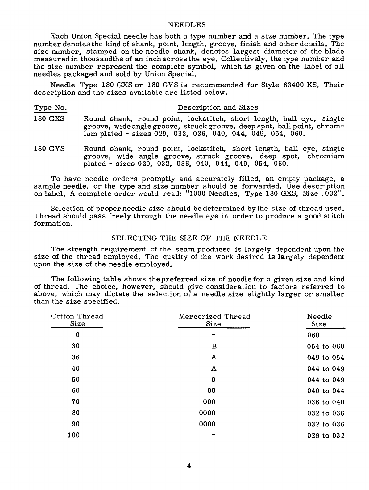
NEEDLES
Each
number
size
measured
the
needles
description
Type
180
180
sample
on
label.
Thread
formation.
denotes
number,
size
number
packaged
Needle
No.
GXS
GYS
To
have
needle,
Selection
should
Union
in
A
Special
the
stamped
thousandths
represent
and
Type
and
the
Round
groove,
ium
plated -sizes
Round
groove,
plated -sizes
needle
or
complete
of
proper
pass
kind
180
sizes
shank,
shank,
the
freely
needle
of
on
of
sold
GXS
available
wide
wide
orders
type
order
needle
has
shank,
the
needle
an
inch
the
complete
by
Union
or
180
round
angle
round
angle
029,
promptly
and
would
size
through
both a type
point,
shank,
across
Special.
GYS
is
are
listed
Description
point,
groove,
029, 032,
point,
groove,
032,
size
number
read:
should
the
036,
and
needle
number
length,
the
symbol,
lockstitch,
struck
lockstitch,
"1000
groove,
denotes
eye.
recommended
below.
groove,
036, 040, 044,
struck
040, 044,
accurately
should
Needles,
be
determined
eye
and a size
finish
largest
Collectively,
which
and
groove,
in
is
for
Sizes
short
deep
short
049,
filled,
be
forwarded.
Type
by
order
given
length,
spot,
049,
length,
deep
054,
the
to
number.
and
other
diameter
the
on
Style
ball
054,
060.
an
empty
180
GXS,
size
produce a good
type
the
63400
ball
point,
060.
ball
spot,
Use
of
thread
details.
of
number
label
KS.
eye,
eye,
chromium
package,
description
Size . 032".
The
the
single
chrom-
single
type
The
blade
and
of
all
Their
used.
stitch
a
The
size
upon
The
of
thread.
above,
than
the
Cotton
of
the
the
which
size
SELECTING
strength
thread
size
following
The
Thread
Size
0
30
36
40 A
50
60
70
80
requirement
employed.
of
the
needle
table
choice,
may
specified.
dictate
employed.
shows
however,
the
THE
of
the
The
quality
the
preferred
should
selection
SIZE
seam
Mercerized
OF
produced
of
the
size
give
of a needle
000
0000
THE
consideration
Size
B
A
0
00
work
of
needle
size
Thread
NEEDLE
is
largely
desired
dependent
is
for a given
to
factors
slightly
largely
size
larger
upon
dependent
and
referred
or
smaller
Needle
Size
060
054
to
049
to
044
to
044
to
040
to
036
to
032
to
the
kind
to
060
054
049
049
044
040
036
90
100
0000
4
032
029
to
to
036
032
Page 5
IDENTIFYING
PARTS
Where
Parts
which
appear.
OF
replacement
listed
Each
bled
with
cular
throat
too
distinguish
Part
IMPORTANT!
MACHINE
The
arrangement
Exploded
in
this
plate
position.
their
view
plate,
the
construction
small
numbers
presents a sector
part
being
for a complete
one
part
represent
ON
FOR
parts
view
catalog
On
feed
WHICH
for
plates
and
the
page
numbers,
shown.
dog,
of
Style
and
permits,
from
ALL
ORDERING
this
at
Style
opposite
descriptions
Following
presser
another
the
ORDERS,
PART
catalog
63 400 KS.
the
back
63400 B covered
of
the
catalog
same
IS
ORDERED.
OF
is
cover
machine,
the
illustration
and
the
foot
each
part,
PLEASE
exploded
part
stamping
that
is
similar.
regardless
REPAIR
to
facilitate
the
differences
in
parts
the
number
combinations
is
stamped
are
identified
in
of
INCLUDEPARTNAMEANDSTYLE
PARTS
easy
Catalog
being
will
view
No.
be
of
pieces
plates,
available
with
its
by
letter
appearance.
the
catalog
and
accurate
between
121 M
aligned
found a listing
are
the
(Second
as
in
required
plates
for
these
part
Standard
number.
symbols
in
which
ordering
Edition).
their
assem-
of
the
in
the
covering
machines.
Style
parts
parti-
they
of
the
Numbers
the
position
in
ordering
exploded
Sub-assemblies,
or a solid
can
be
furnished
description
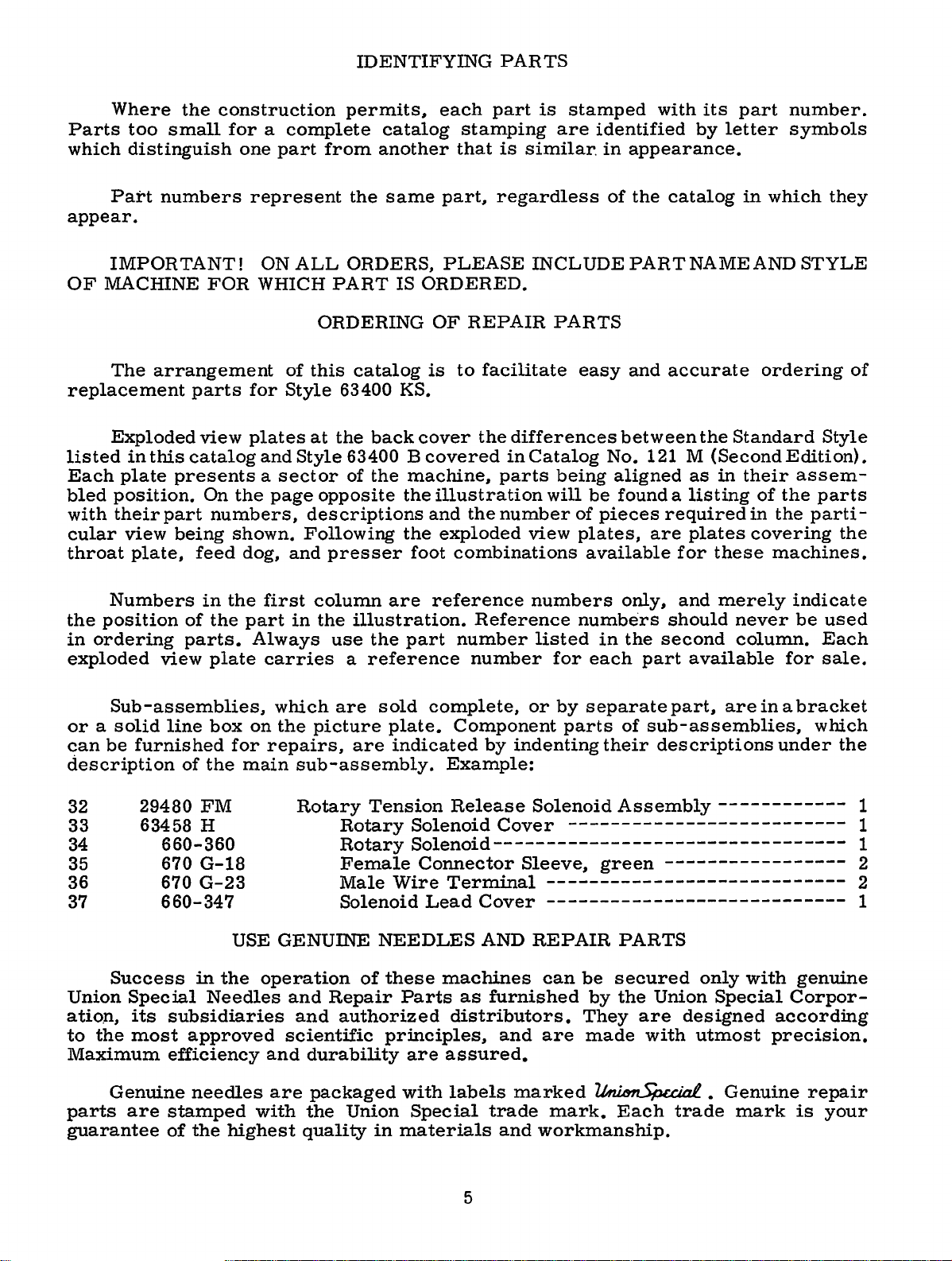
32
33
34
35
36
29480
63458 H
37
Success
Union
ation,
to
Maximum
the
Special
its
most
in
the
of
the
part
parts.
view
660-360
670
670
line
of
plate
box
for
the
FM
G-18
G-23
main
660-347
USE
in
the
Needles
subsidiaries
approved
efficiency
first
Always
carries
on
operation
column
in
the
which
the
picture
repairs,
sub-assembly.
Rotary
GENUINE
and
and
scientific
and
durability
are
reference
illustration.
use
the
part
a
reference
are
sold
plate.
are
indicated
Tension
Rotary
RotarySolenoid---------------------------------
Female
Male
SolenoidLeadCover
of
Repair
authorized
Solenoid
Connector
Wire
NEEDLES
these
Parts
principles,
are
Reference
number
number
complete,
Component
Example:
Release
Terminal
AND
machines
as
distributors.
assured.
numbers
listed
or
by
indenting
Solenoid
Cover
Sleeve,
----------------------------
----------------------------
REPAIR
can
furnished
and
are
only,
numbers
in
for
each
by
separate
parts
their
Assembly
-------------------------green
PARTS
be
secured
by
the
They
made
should
the
second
part a vail
part,
of
sub-assemblies,
descriptions
-----------------
Union
are
with
and
merely
never
column.
able
are
------------
only
Special
designed
utmost
indicate
be
for
in a bracket
which
under
with
genuine
Corpor-
according
precision.
used
Each
sale.
the
1
1
1
2
2
1
Genuine
parts
guarantee
are
needles
stamped
of
the
highest
are
with
packaged
the
Union
quality
with
Special
in
materials
labels
trade
5
marked
mark.
and
workmanship.
~
Each
•
trade
Genuine
mark
repair
is
your
Page 6
TERMS
Prices
are
forwarded
otherwise
CAUTION!
on
hand
Before
carefully
packing
PREPARATION
A
bag
attaching
cellaneous
lead
wire
tension
Insert
the
upper
are
directed.
wheel.
leaving
packed.
box,
of
screw,
attachment
clamp,
release
hinge
frame
the
strictly
f. o.
b.
A
When
Using
assembly
solenoid
both
factory,
After
following
OF
MACHINE
one
one
studs
eyelet
net
cash
shipping
charge
unpacking,
the
parts,
extra
to
screw
lead
in
to
hands
each
machine
steps
bobbin,
the
for
holes
top
is
bed
wire.
of
and
subject
point.
made
DO
on
Union
should
FOR
consisting
plate,
synchronizer
provided
arm.
Parcel
to
INSTALLING
NOT
bed
casting,
Special
and
be
INSTALLATION
two
one
to
change
Post
cover
lift
accessories
hinge
for
the
machine
lift
machine
followed:
of
one
studs,
synchronizer
lead
them
without
shipments
postage
out
gently.
have
frame
two
wire
in
rear
and
of
box
is
sewed
been
thread
screws
bracket,
clamp
of
notice.
are
insurance.
by
placing
off,
removed
eyelet,
for
one
and
three
cloth
plate.
All
shipments
insured
one
inspected
from
one
holding
synchronizer
clamps
Assemble
unless
hand
and
the
eyelet
mis-
for
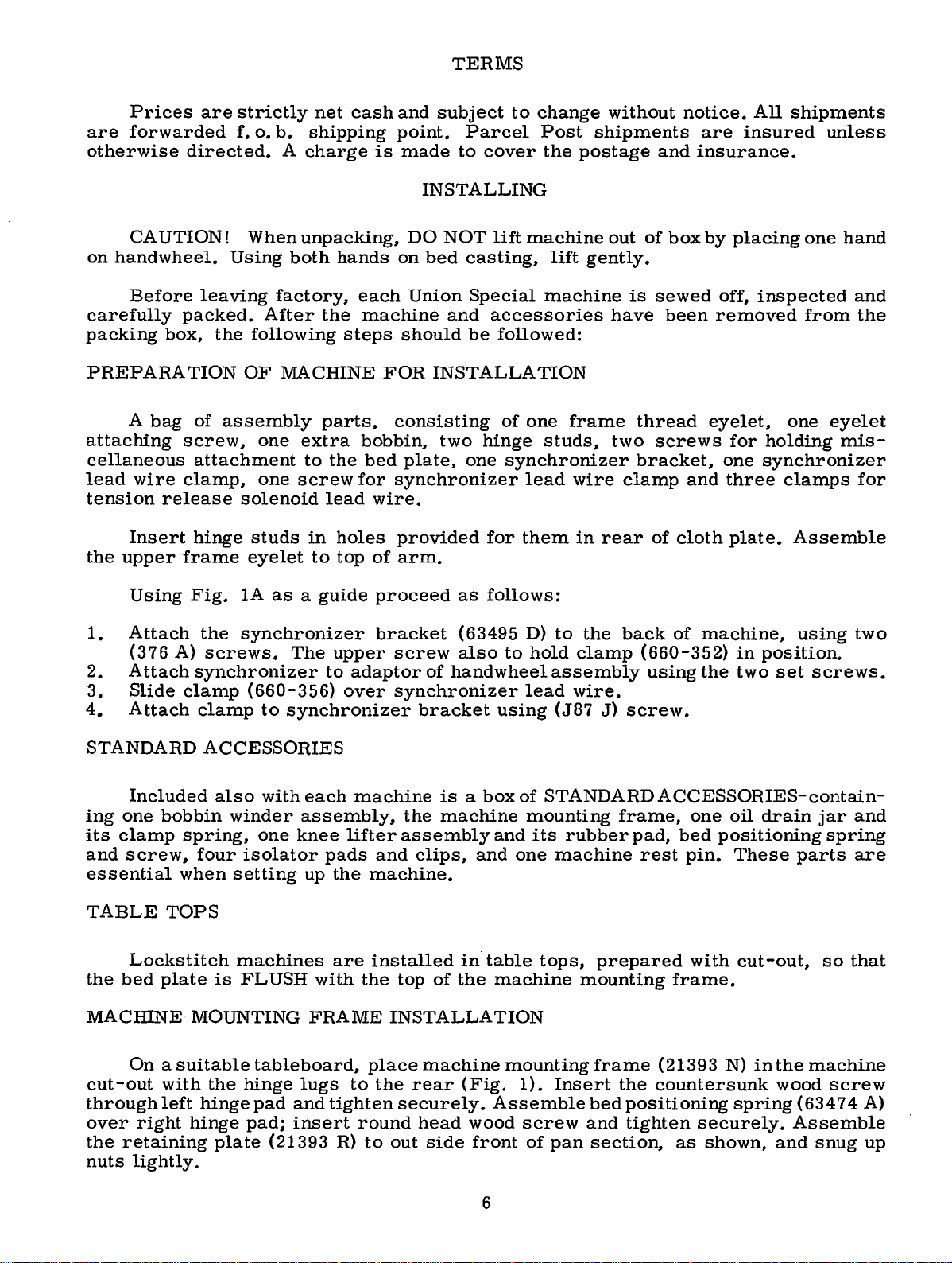
Using
1.
Attach
(376
A)
2.
Attach
3.
Slide
4.
Attach
STANDARD
Included
ing
one
its
clamp
and
screw,
essential
TABLE
Lockstitch
the
bed
MACHINE
clamp
bobbin
spring,
when
TOPS
plate
Fig.
MOUNTING
lA
as a guide
the
synchronizer
screws.
synchronizer
clamp
ACCESSORIES
also
winder
four
isolator
setting
machines
is
FLUSH
The
(660-356)
to
synchronizer
with
each
assembly,
one
knee
up
FRAME
upper
to
over
pads
the
are
with
proceed
bracket
screw
adaptor
machine
lifter
and
machine.
installed
the
of
synchronizer
bracket
is a box
the
machine
assembly
clips,
top
of
INSTALLATION
as
follows:
(63495
also
hand
wheel
and
and
in
table
the
machine
D)
to
hold
assembly
lead
using
of
STANDARD
mounting
its
one
tops,
to
the
clamp
wire.
(J87
J)
frame,
rubber
machine
prepared
mounting
back
of
machine,
(660-352)
using
screw.
ACCESSORIES-contain-
pad,
bed
rest
pin.
frame.
in
the
two
one
oil
positioning
These
with
cut-out,
position.
set
drain
using
screws.
jar
spring
parts
so
two
and
are
that
On a suitable
cut-out
through
over
the
nuts
right
retaining
lightly.
with
left
hinge
hinge
the
plate
hinge
pad;
tableboard,
lugs
pad
and
tighten
insert
(21393 R)
place
to
the
round
to
machine
rear
securely.
head
out
side
mounting
(Fig.
Assemble
wood
front
6
1).
Insert
screw
of
pan
frame
the
bed
positioning
and
tighten
section,
(21393
countersunk
as
N)
spring
securely.
shown,
in
the
wood
and
machine
screw
(63474
Assemble
snug
A)
up
Page 7
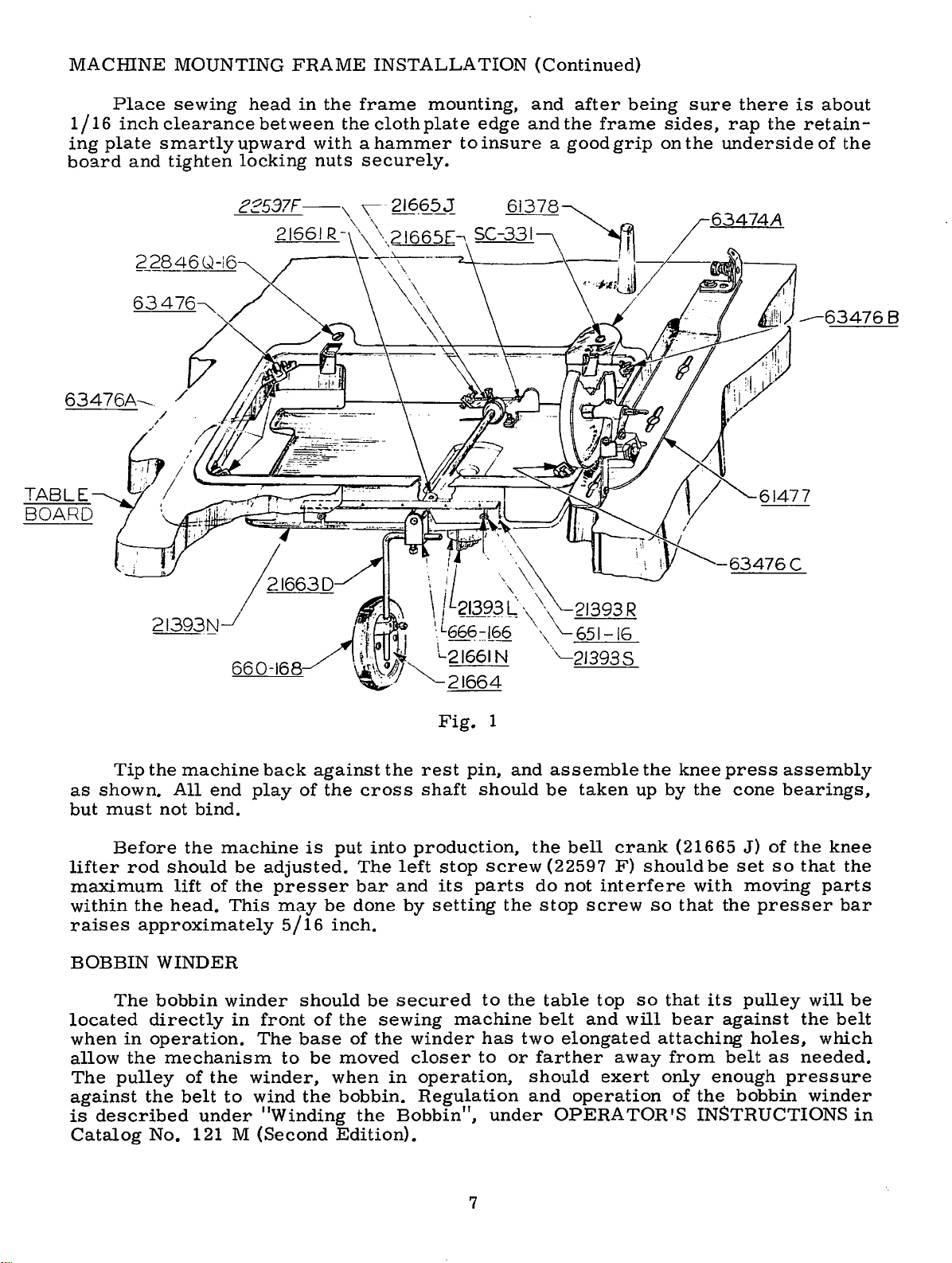
MACHINE
MOUNTING
FRAME
INSTALLATION
(Continued)
1/16
ing
plate
board
Place
inch
and
sewing
clearance
smartly
tighten
head
between
upward
locking
in
the
frame
the
cloth
with a hammer
nuts
securely.
mounting,
plate
edge
to
insure a good
and
and
after
the
being
frame
grip
sure
sides,
on
the
there
rap
the
underside
-63476C
is
about
retain-
of
the
Tip
as
shown.
but
must
Before
lifter
rod
maximum
within
raises
the
approximately
BOBBIN
The
located
when
allow
The
in
the
pulley
against
is
described
Catalog
the
machine
All
end
not
bind.
the
should
lift
of
head.
WINDER
bobbin
directly
operation.
mechanism
of
the
the
belt
under
No.
121 M
back
play
machine
be
adjusted.
the
presser
This
may
5/16
winder
in
front
The
to
winder,
to
wind
"Winding
(Second
against
of
the
is
put
be
inch.
should
of
the
base
be
moved
when
the
bobbin.
Edition).
cross
into
The
bar
done
be
sewing
of
the
the
Fig.
the
rest
shaft
production,
left
stop
and
its
by
setting
secured
winder
closer
in
operation,
Regulation
Bobbin",
1
pin,
and
should
screw
parts
the
to
the
machine
has
to
or
under
assemble
be
the
(22597
do
not
stop
table
belt
two
elongated
farther
should
and
OPERA
taken
bell
crank
F)
interfere
screw
top
and
will
away
exert
operation
TOR'S
the
knee
up
by
(21665
should
so
that
so
that
bear
attaching
from
only
of
press
the
be
with
the
its
against
belt
enough
the
cone
assembly
bearings,
J)
of
set
so
moving
presser
pulley
holes,
as
pressure
bobbin
the
that
parts
will
the
which
needed.
winder
INSTRUCTIONS
knee
the
bar
be
belt
in
7
Page 8
CLAMP
J87J
*
SCREW
!''
DIA.
(BRACKET)
SEE DETAIL
DRILL
00
UNDERTRIMMER
FOR
63400
TilE
&.
SHOWN
z<?J48DJII
BUT
SWITCH
*INDICATES
DIMENSIONS
NOT EQUIPPED
**INDICATES
800L
T-362
KNEE
I"
if
DIA.
E.LE.CTRONIC. EQUIPMENT
&!J900
SERIES
DRILLED
·KNEE
MACHINE
IN
IN
SWITCHj
PART
INCLUDED
FOR
WITH
STANDARD
PART
INCLUDED
I~
QV~\Lj:\BLE.
f!LIMINAT£5
L FROM
J RELEASE SOLENOID
).,
FROM
) SOLENOID
PART
PACKING.
HOLES.
29480HP
(EXTRA
HOLES
WHICH
BOX
ARE
S£ND
TREADL\Nt
TENSION-
C.UTTING.
NUTS
SECURE
* *
TRIMME:'R
BOARD W/TI-4
NOTE
: REMOVE PQWE.R
FlroM
BOX AND
PRINTtrD
CIRCUIT
WITH
SCR£115.
Na
800LT-3G2
FOR INSTALLATIONS
IS
NOT
PART
&
CHARGE).
5WITC.\4
TO
CIRCUIT'
RELAYS
INSERT
TRIMMER
BOARD
OF
BOX
----'-_....
PACK
/tSECUR£
II"
(APPROXJ-____,.~
SCREW.S
PUSH
BUTTON
CONNECTED
INSIDE.
OF
SWITCH
SOX
Fig.
lA
Page 9
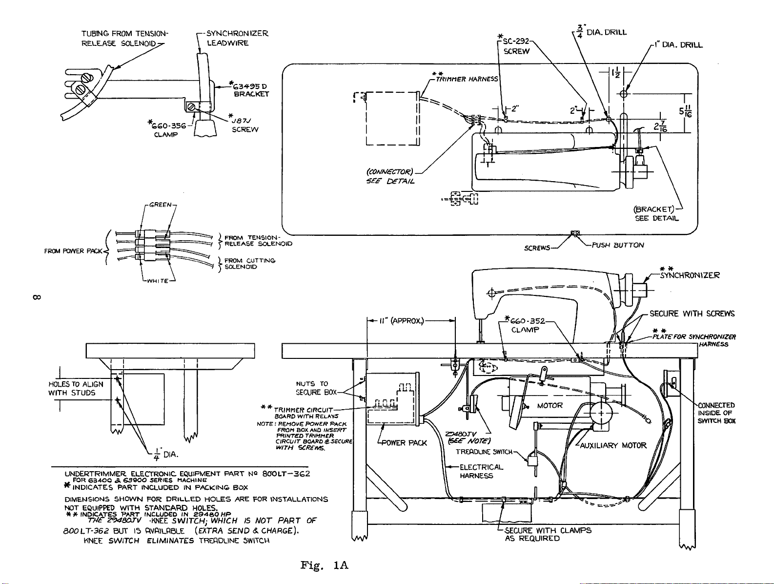
BELTS
Th
ese
machines
PREPARATION
Once
1.
Wi
l
2. A
Drill
3.
Attach
4.
Secure electrical
using
clutch
5.
Connect
release
green
6.
Assemble relays
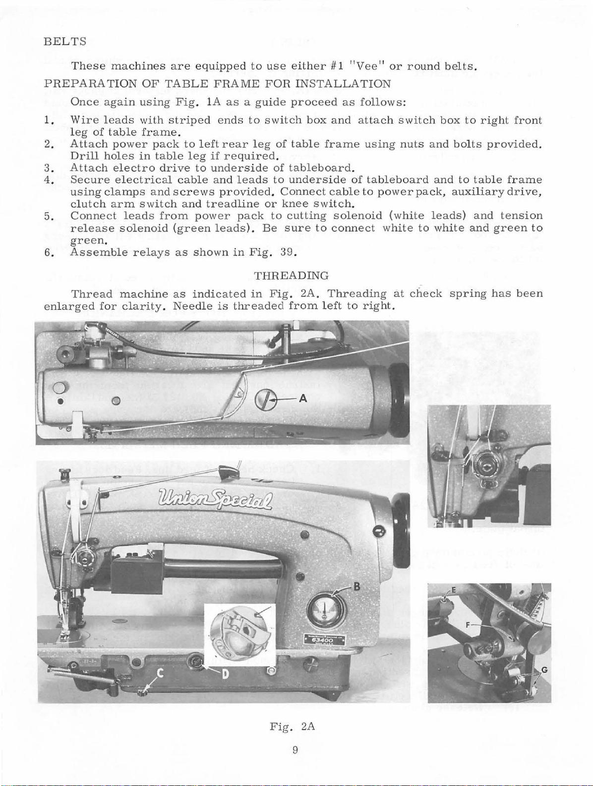
Thread
enlarg
eg
tt
ed
re
of
ach
again
leads
tab
power
holes
electro
clamps
arm
leads
solenoid (green
.
machine
for
clarity.
OF
TAB
using
with
stri
le
frame.
pack
in
table
drive
and
switch and
from
are
equipped
LE
Fig
.
ped
to
left
leg
to
cable
screws
power
as
shown
as
indicated
Needle
FRAME
lA
as a guide
ends
to
rear leg
if
required
underside
and leads
to use
either
FOR
proceed
switch
of
tab
.
of
tableboard
to
und
provided. Connect
tread
line or
pack
leads).
in
Fig
Be
.
knee
to
cutting
sure
39.
THREADING
in
Fig.
is
threaded
from
# 1 "Vee
11
INSTALLATION
as
follows:
box
and
attach
le
frame
using
.
erside
switch
cab
of
tableboard
l e
to
power
.
solenoid (white
to
connect
2A.
Threading
left
to
right.
or
round
switch
nuts
pack, auxiliary drive,
white
to
at
check spring
belts
box
and
bolts
and to
leads)
white
.
to
table
and
and
right
front
provided
frame
tension
green
has
been
.
to
Fig
. 2A
9
Page 10
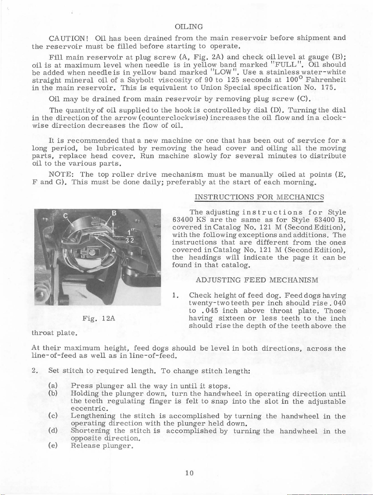
OILING
CAUTION!
the
reservoir
Fill
oil
is
be
added
straight
in
the
Oil
The
in
the
wise
long
parts,
oil
F
direction
It
period,
to
NOTE:
and
main
at
maximum
when
mineral
main
direction
is
the
G).
reservoir.
may
be
quantity
recommended
replace
various
The
This
Oil
has
been
must
reservoir
be lubricated
be
level
needle
drained
of
decreases
head
must
is
oil
of a Saybolt
of
oil
the
arrow (counterclockwise)
cover. Run machi
parts
top
roller
be
filled
at plug
when
in
This
from
supplied
that a new
.
done
drained
before
yellow
is
the
flow
by
drive
daily;
starting
screw (A,
needle
band
viscosity
equivalent
main
reservoir
to
the
of
machine
removing
mechanism
preferably
from
is
hook
oil.
63400
covered
with
instructions
covered
the
found
the
main
to
operate.
Fig.
2A)
in
yellow
marked ''LOW".
of
90
to
to
Union
by
removi
is
controlled
increases
or
one
the
head
ne slowly
must
at
INSTRUCTIONS
The
adjusting
KS
are
in
Catalog
the
following
in
Catalog
headings
in
that
reservoir
and
band
125
Special
that
cover
for
be
the
start
the
that
will
catalog
before
check oil
marked "FULL". Oil
Use a stainless
seconds
specification
ng
plug
by
dia
the
has
been
and
several
manually oiled
of
FOR
instructions
same
No
. 1
exceptions
are
different
No
. 121 M
indicate
.
level at gau
at
screw
l (D).
oil
flow
out
oiling
minutes
each
MECHANICS
as
for
21
M (
the
100°
Turning
and
of
all
morning
Sty
Second
and
additions.
from
(Second
page
shipment
water-white
Fahrenheit
No.
(C).
in a clock
service
the
to
at
le
and
ge
(B);
should
175.
the dial
for
moving
distribute
points
.
for
63400
Edition),
the
Edition),
it
(E,
Sty
The
ones
can
-
a
l e
B,
be
throat
At
line-of-feed
2.
their
Set
(a)
(b)
(c)
(d)
(e)
plate.
maximum
stitch
Fig.
as
Press
Holding
the
eccentric.
Lengthening
operating
Shortening
opposite
Release
well
to
required
plunger
teeth
12A
height,
the
regulating
direction.
plunger.
feed
as
in
line-of-feed.
length. To
all
plunger
the
stitch
direction
the
stitch
the
down,
finger
with
1.
dogs
should
change
way
in
until
turn
is
is
accomplished
the
plunger
is
accomplished
ADJUSTING
Check
twenty-two
to . 045
having
should
the
felt
height
rise
be
level
stitch
it
stops
handwheel
to
snap
held
of
teeth
inch
sixteen
the
in
length:
.
into
by
turning
down
by
turning
FEED
feed
per
above
or
depth
both
in
operating
the
.
MECHANISM
dog.
Feed
inch
should
throat
less
of
the
directions,
slot
the
the
plate.
teeth
teeth
direction
in
the
handwheel
handwheel
dogs
having
rise.
Those
to
the
above
across
until
adjustable
in
in
040
inch
the
the
the
the
10
Page 11
ADJUSTING
FEED
MECHANISM
(Continued)
NOTE:
Stitch
through
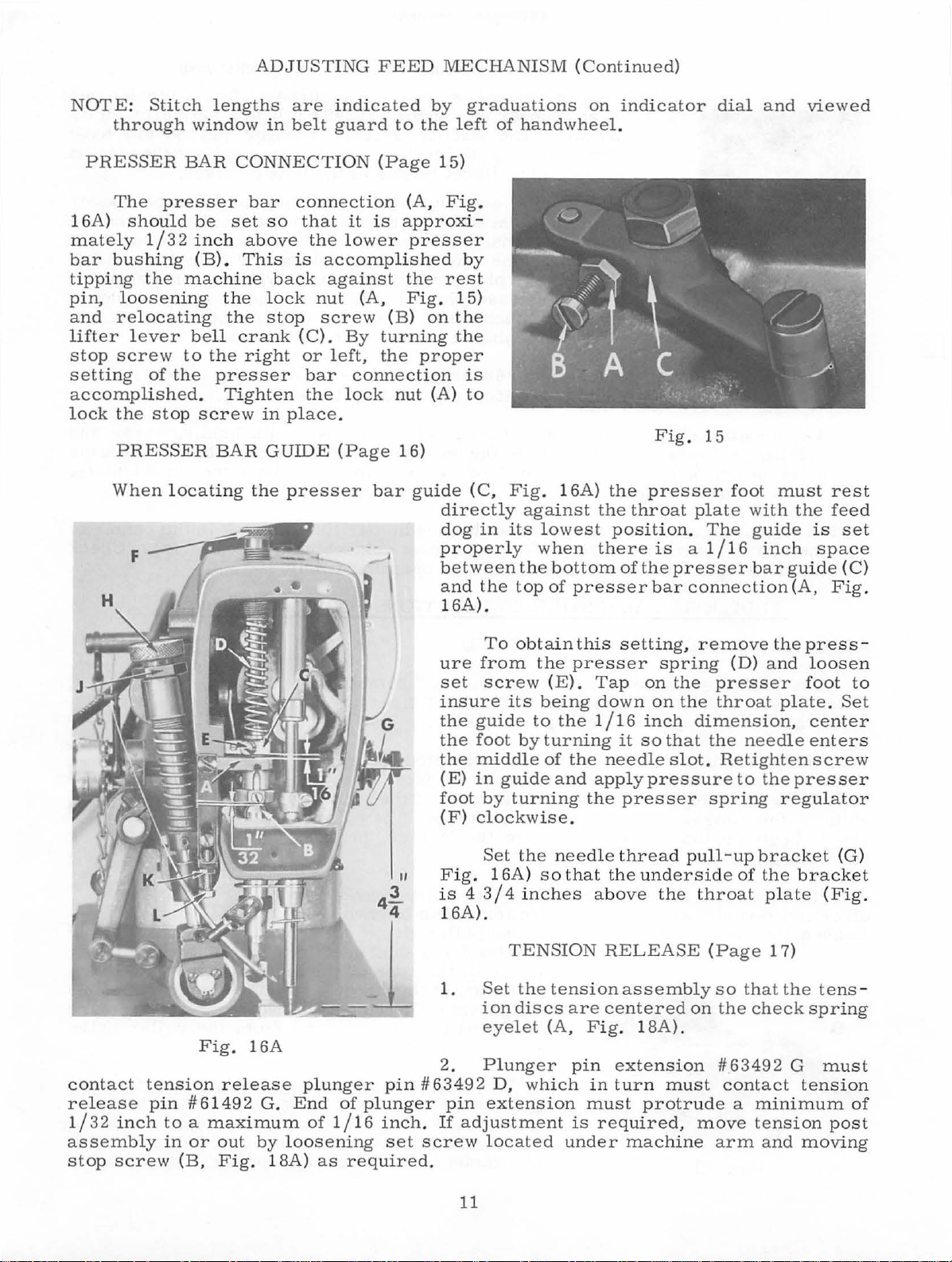
PRESSER
The
16A)
mately
bar
bushing
tipping
pin,
and
lifter
stop
setting
presser
should
1/32
the
loosening
relocati
lever
screw
of
accomplished
lock
the
stop
PRESSER
When
lengths
window
BAR
be
set
inch
(B).
machine
the
ng
the
bell
to
the
the
presser
.
Tighten
screw
BAR
locating
are
indicated
in
belt
guard
to
CONNECTION (Page
bar
above
This
crank
right
connection
so
that
it
the
low
is
accomp
back
against
lock nut (A,
stop
screw
(C).
or
By
left,
bar
the
lock
in
place.
GUIDE
the
presser
(Page
(A,
is
approx
er
presser
lished
the
Fig.
(B)
turning
the
proper
connection
nut
16)
bar
guide
by
the
left
15)
Fig.
by
rest
15)
on
the
the
(A)
directly
dog
properly
between
and
16A).
graduations
of
handwheel.
i-
is
to
(C,
Fig.
against
in
its lowest
wh
the
bottom
the
top
of
on
16A)
en
presser
indicator
Fig.
the
presser
the
throat
plate
position. The
there
of
is
the
bar
presser
a 1
connection
15
dial
foot
/16
and
must
with
guide
inch
bar
viewed
the
is
space
guide
(A,
rest
feed
set
(C)
Fig
.
contact
release
1
/32 inch
assembly
stop
screw
Fig. 16A
tension
release
pin #61492
to a maximum
in
or
out
(B,
Fig.
plunger
G.
End
of plun
of
1/ 16
by loosening
18A)
as
required.
ure
set
insure
the
the
the
(E)
foot
(
F)
F ig.
is 4 3 I 4
16
1.
2.
pin
#63492
ger
pin
inch.
set
If
screw located
To
obtain
from
the
screw (E). Tap
its
being
guide
foot
middle
in
by
to
by
guide
turning
the
turning
of
the
and
clockwise.
Set
the
needle
16
A)
so
that
inches
A).
TENSION
Set
the
tension
ion
discs
eyelet
are
(A,
Plunger
D,
which in
extension
adjustment
under
this
setting,
presser
down
1 I
needle
app
the
spring
on
on
16
inch
it
so
ly
pressure
presser
the
the
that
slot. Retighten
thread
the und
above
erside
the throat
RELEASE (Page
assemb
centered
Fig
. 18A) .
pin
extension
turn
must
is
required,
must
protrude a minimum
mac
hine arm and
remove
(D)
presser
throat
dim
ension, center
the
needle
to
the
spring
pull-up
bracket
of
the
plate (Fig
ly
so
that
on
the
check
#63492
contact
move
tension
the
press
and
loosen
foot
plate.
ente
screw
presser
regulator
bracket
1 7)
the
tens
spring
G
tens
moving
-
to
Set
rs
(G)
.
-
must
ion
of
post
11
Page 12
3.
Tension
l
ease
bracket.
approximately
release
TENSION
release
plunger
The
pin
without
RELEASE
solenoid
pin
bushing
tension
.
005
inch
thread
(Page
is
#63492 F with a set
release
clearance
in
1 7)
secured
plunger
between
the
tension
(Continued)
to flat
pin
it
discs
of
tension
screw
should
and
.
the
re-
in
its
have
tension
Fig.
4.
NOTE:
ADJUSTING
18A
The
manual
thread
The
tension
raising
point
Tighten
the
the
is
Head
slot
oil
ADDITIONAL ADJUSTING
tens
tension
or
lowering
between
screw
oiler
in
the
gauge
TOP
ion
when
release
1/4
securely.
bracket
connecting
to
be
sure
DRIVEN
This
between
end
should
contacts
tension
exert
After
release
the
presser
cam
it
to
to
must
it
ROLLER
can
be
the
of
the
tension
then
the
release
too
much
tightening
cam#
can
be
suit
sewing
5/16
rod.
inch
locate
The
reads
INSTRUCTIONS
accompli
head
be
slipped
plunger
plunger
pressure
set
63458 J should
foot
is
positioned
of
the
wick
full
and
FEED
shed
of
the tension
release
pin
screw
raised
conditions. The
presser
needle
must
operates
by
pin.
on
to
bushing
extension,
pin.
thereby
remove
be
for
by
loosening
foot
bar
contact
FOR
placing
release
The
Care
opening
set
so
back
lift
link
the
freely.
STYLE
a . 005 inch
plunger
tension
and
which
should
spacer.
that
tacking.
its
average
above
oil
wick
need
le
63400
release
moved
in
turn
be
the
tension
it
will
holding
tension
the
throat
in
the
bearings.
pin
in
taken
not
screw
center
KS
spacer
and
the
solenoid
until
contacts
release
release
it
not
to
discs.
and
plate.
of
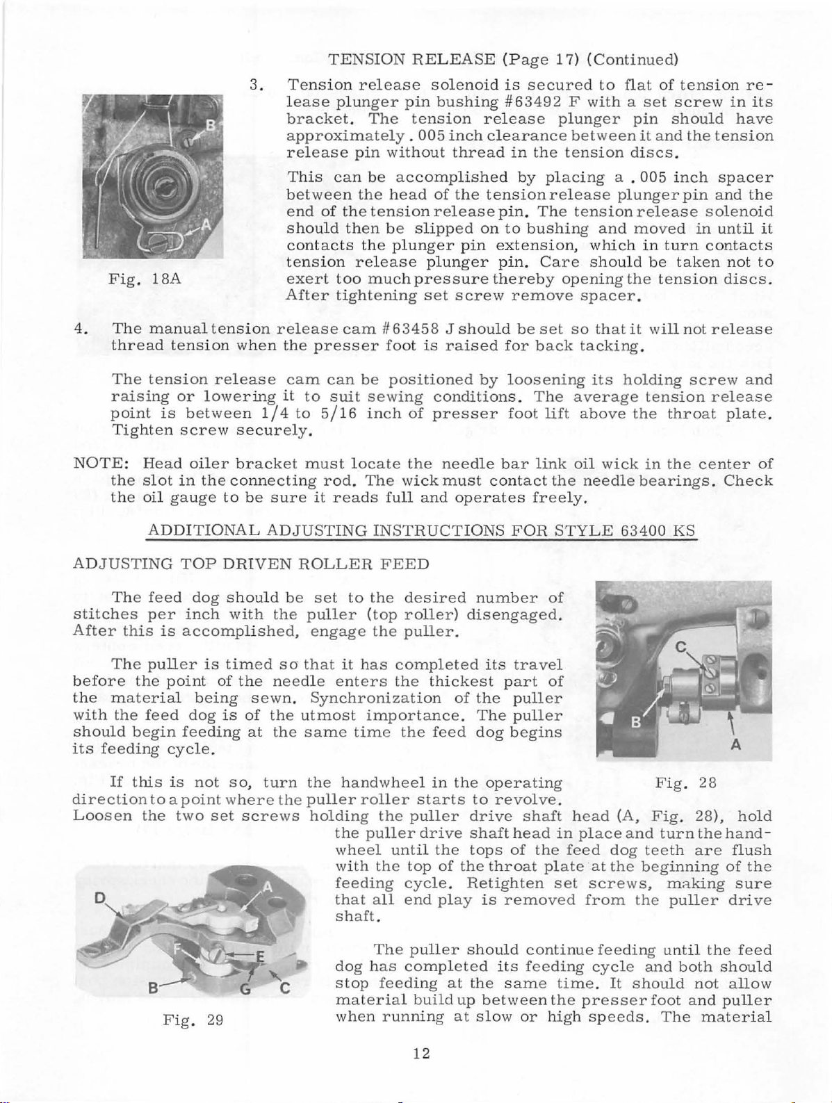
Check
The
stitches
After
before
the
with
should
its
direction
Loosen
this
The
material
the
feeding
If
feed
per
is
puller
the
point
feed
begin
cycle
this
is
to a point
the
Fig.
dog
should
inch
accomplished,
feeding
two
is
being
dog
.
not
set
29
of
is
with
timed
the
sewn.
of
at
so,
turn
where the
screws
be
set
the
puller
engage
so
that
it
needle
the
the
enters
Synchronization
utmost
same
the
handwheel
puller
holding
the
wheel
with
feeding
that
shaft.
dog
stop
material
when
to
the
desired
(top
roller)
the
puller.
has
completed
the
importance.
time
roller
the
puller
until
the
all
The
has
feeding
running
the
top
cycle.
end
completed
thickest
feed
in
starts
puller
drive
the
of
play
puller
build
number
disengaged.
its
part
of
the
The
dog
the
operating
to
revolve.
drive
shaft
tops
the
throat
Retighten
is
removed
shou
ld
its
at
the
same
up
between
at
slow
of
travel
of
puller
puller
begins
shaft
head
of
the
plate
continue
feeding
or
high
in
feed
set
time
the
head
place
dog
at
the
screws,
from
feeding
cycle
.
It
presser
speeds.
Fig
(A,
Fig
and
teeth
beginning
the
and
shou
foot
. 28
. 28),
turn
the
are
m;:tking
puller
until
both
ld
not
and
The
material
hand-
flush
of
sure
drive
the
should
allow
puller
hold
the
feed
12
Page 13
ADJUSTING
TOP
DRIVEN
ROLLER
FEED
(Continued)
should
feed
hand
decre
travel.
under
be
dog.
This
thread)
ase
Retighten
Make
the
kept
adjustment
the
sure
puller
uniformly,
feeding.
creases
Locking
Turning
the
nut
NOTE: Top
slightly
(
K)
and
tions. Ret
taut
at
is
on
the
end
puller
roller
lock
PRESSURE
there
is
roller. The
but
be
sure
the
pressure and
(J)
is
provided
roller
before
raising
ighten
can
or
or lowering
nut.
all
times.
accomplished
of
the
puller
travel
nut
(B).
ON
TOP
enough
pressure
puller
there
is
enoughpressure
regulator
counterclockwise
to
maintain this
be
adjusted
after
the
screw
The
puller
by
loosening
regulating
or
counterclockwise
ROLLER
on
should
(H,
Fig.
to
lift simult
presser
foot,
(L)
should
FEED
th e
cross
16A)
acts
setting
by
to suit
not
lock
stud.
Turn
to
material
over
to
insure
clockwise
the
reverse.
.
aneously
loosening
sewing
feed
nut
increase
going
seams
good
with
condi-
faster
(
B,
screw
in-
nut
Fig.
,
than
28) (
it
(C)
clockwise
the
puller roll
that
of
has a left
the
to
er
D
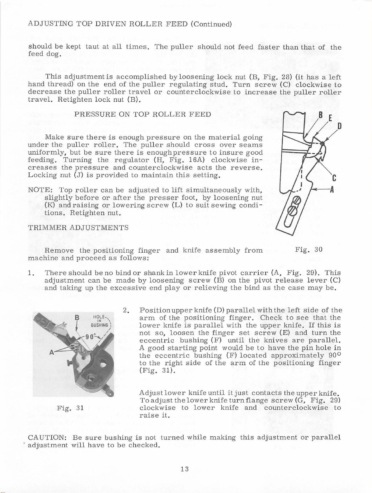
TRIMMER
Remove
machine
1.
Th
ere
adjustment
and
taking
F ig. 31
ADJUSTMENTS
the
positioning
and
proceed
should
can
up
be
the
no
be
finger
as
follows:
bind
or
made
by
excessive
2.
lower
A
Adjust
and
shank
in
loosening
end play
Position
arm
of
knife
not
so,
eccentric
good
the
to
(Fi
starting
eccentric
the
right
g.
31).
lower
To
adjust
clockwise
raise it.
knife
lower
or
upp
er knif
the
positioning
is
loos
en
bushing
side
the
lower
to lower
assembly
knife pivot
screw
relieving
e (D)
parallel
the
finger
(F)
point
bushing
of
knife
until
knife turn
from
carrier
(B)
on
the
pivot
the
bind
parallel
finger.
with
the
set
screw (E)
until the knives
wo
uld
be
(F)
loca
the
arm
of
it
just
contacts
flange
knife
and
Fig
(
A,
Fig.
release
as
the
case
with the left
Check
upper
knife
to
side
see
.
and
are paralle
to
have
ted
the
the pin hole
approximate
positioning
the
upper
screw
(G,
counterclockwise
.
30
29).
lever
may
that
If
th
turn
ly
finger
knife.
Fig.
This
be.
of
is
90°
(C)
the
the
is
the
l.
in
29)
to
CAUTION:
·
adjustment will
Be
sure
have
bushing
to
be
is
not turned
checked.
while
making
13
this adjustm
ent
or
parallel
Page 14

TRIMMER
Place
bobbin
ing
screws
projection
4.
Locate
as
far
of
feed.
ing
the
releaselever
ance
Fig
. 33)
ADJUSTMENTS
Fig. 32
the
projection
case
holder
securely,
and
the
the
cutting
forward
With
cutting
to
be
is
as
possible
the
cutting
solenoid
(D),
maintained
in
position.
(Continued)
(A,
Fig.
recess
(B)
allowing
inside
edge
solenoid
and
soleno
plunger
sothatthereis
when
knife
treme
the
ger (B).
the
cide
dicated
ments
tion
3.
12A,
and
1/32
of
Page
tighten
inch
bobbin
bracket
parallel
id lever
(C),
adjust
a1/32inchclear
return
The
lower
left
left
side
As
run
out
at a point
at
loosen
knife
.
Assemb
assemb
case
holder
assemb
holder
10)
the
clearance
case
(A,
Fig. 3 2)
with the
(B)
contact-
the
spring
knife
position
of
the
the
lower
of
the
of
point
screws
le
positioning
ly
into
ly
by
until
the
on
the
finger
recess
line
pivot
-
(A,
(A,
Fig.
shou
ld
not
arm
of
the
knife
cutting
the
positioning
(D).
To
(A,
moves
edge
make
Fig.
machine.
positioning
turning
finger
recess
positioning
and
knife
between the
(Fig.
12A).
30)
extend
positioning
to
(C)
must
finger
these
31)
finger
Adjust
the
finger
the
bobbin
is
finger
assembly
outside
in
the
and
and
and
at
into
its ex-
beyond
fin
right,
coin
as in-
adjust
pos
i-
knife
bobbin
knife
case
the
top
the
attachedge
of
-
-
-
.
5.
Adjust
when
position,
the
holder.
CAUTION:
making
the
the
lower
the
left
side
this adjustm
Fig.
lower
left
of
Be
sure
34
knife
knives
corner
the
needle
ent.
stop
in
(E,
cutting
Also
screw
its
Fig.
slot
(B,
extreme
30)
in
the
is
solenoid lever
be
sure
6.
Be
sure
contacts
knife
the
spring
retainer
NOTE:
ting solenoid
ine
or
7.
Knifereturnspring(A,
tension
knifereturnspringloosenscrew(C)
tension
crease
tension
Fig.
right
in
line
bobbin
knife
the
the
is
in
wire
If
position
to
spring
tension
.
33)
so
hand
with
case
contacts
does
not
spring
bobbin
its
extreme
wire
to
does
suit
positioning
bracket are
changed,
cut
threads.
bracket
or
the
lower
hit
the
retainer
case
holder
right
not
.
finger
removed
Fig.
To
(D)
to
the
Fig
knife
hook
wire
hand
make
assembly
check
33) t
adjust
to the
left
. 33
stop
point
when
(B,
.
Fig.
the
position
contact,
from
step
5.
ohaveproper
tension
and
right
to
decrease
when
lower
bend
or
mach
move
to in-
31)
.
cut
the
If
-
-
of
14
Page 15

SYNCHRONIZER
(a)
(b)
Rotate
deflector
with
At
band
front
make
and
(
a),
handwheel
the
needle
this
time
(A,
edge
this
deflector
then
plate
Fig.
loosen
chronizer
(c)
The
needle
power
needle
at
off
rotate
bottom
bottom. Then
of
synchronizer
(d)
from
its
plastic
The
or
in
end
the
positions
left
(E)
brush
band.
needle
1/8
inch
operating
of
synchronizer
midd
l e
of
ADJUSTMENT
in
(C,
Fig.
on
the
the
brass
34}
should
of
the
brush
adjustment
plate
as
set
and
move
positioner
of
handwheel
loosen
and
in
operating
is
in
the
positioner
from
the
direction
of
the black
the
needle
operating
12A,
up
stroke
contact
be
holder
position
described
screws
as
required
should
stroke.
screw
rotate
direction
middle
should
top
of
until
and
rotate
plastic
bar.
direction
Page
of
of
flush
with
(B).
need
(C)
in
.
position
If
not,
until
(D)
third
of
the
position
its
up
it
is
at
fourth
band. Turn
10)
the
the
left
the
To
l e
bar
in
step
syn
with
it
is
at
end
band
until
black
needle
stroke.
the
until
on
needle
-
at
If
top
band
the
not,
of
from
on
the
rotating
bar.
thread
with
its
stroke.
power
needle
take-up
power
left
and
hook
Then
(F)
check
clearance
assembly
Fig. 35
at
top
off
rotate
loosen
until
its
the
cut
is
in
of
its
stroke
handwheel
screw
brush
up
and
in
the
line
at
is
in
down
Fig.
36
"Lock Motor
Adjust
as
screw
described
")
just
located
above.
CLUTCH
(a)
(b)
8
2
(c)
A
3
ADJUSTING
(a}
(b)
enough
near
the
Tighten
Set
needle
Adjust
will
ARM
return
SWITCH
in
clutch
approximately
Close
adjusting
it
needle
treadline
and
screw (C),
the
position
setting.
CLUTCH
Depress
indicates
Adjust
1/16
Loosen
to
unlock
top
lock
treadle
switch
clutch
to 1/8
lo
ck
it,
on
right
screw (E).
ADJUSTMENT
work
.
arm
spring
to
stop
1/2
(wing
inch
switch
until
microswitch.
up. Tighten
unit
until
is
open
so
that
clutch
inch
travel
screw
which
end
is
of
motor,
(
A,
Fig
nut
from
and
end
loosen
there
Then
nut
one
click
.
arm
before
(E,
Fig
. 35)
approximate
until
. 3 5)
washer
of
clutch
is
no
contact
tighten
(D)
is
has
clutch
ly
clutch
so
that
treadle
(B)
is
to
stud}.
lever
switch
between
screw
to
until
maintain
heard, which
approximately
is
engaged.
(wh
ere
it
says
one
full
turn.
is
engaged
be
CAUTION!
motor
running;
Clutch
one
must
click
not
must
engage
be
heard
when clutch
before
lever
clutch
15
switch is
is
engaged.
closed
or
auxiliary
Page 16

THREAD
1.
Rotate
( 63 4 70 M)
the
WIP ER
thread
needle
ADJUSTMENTS
wiper
and
the
thread
mounting
thread wiper
when
the
collar
guide
take-up
(63470
holder ( 634
is
at
the
H)
top
and
of
adjust
70
N),
its
the
so
that
stroke.
thread
the
wiper
hook
guide
catches
2. Th
3.
Form thr
(63470 M
rea
d wiper leve
ead
).
r (
6347
0 E)
must
wiper wire (63470 V)
CAUTION!
solenoid
gui
de (
plast
ing
thread
wi
ll
I
NSTALLATION
6347
ic
t~be
result
from
Wheninstallinginching
to
remove
pi
n # 2
and
inch
ing
switc
Should
date, the
or
the
needle
ret
urn
with a snap
for
free
Thread
returning
0 M)
.
Be
so
sure
that
movement
wiper
to
wire
to
its
the
hook
loosen
wiper lever. Premature
if
it
is
not
allowed
OF
INCIDNG
switch,
jumper
pin
h pl
the
jumper
positioning
wire
# 3
on
ug
or
inching
wire
(A,
socket
it
will
switch
(A,
unit
Fig
(B)
Fig.
when
in
released
thread
hook
stop.
Move
does
set
screws
failure
to
return
SWITCH
(670
. 36)
before
not
function
be
removed
36)
will
not
wiper
must not
thread
not
stop
when
completely
B-2
located
connecting
properly
must
be
position
.
prevent
against
adjust
of
solenoid
1)
be
between
at
a l
replaced
up
guide
wiper
.
sure
the
.
ate
.
-
r
or less
Fig. 37
accordingly
by
moving
PUSH
edge
of
the
the
enables
with the
trimmed
BUTTON
If
the
of
the
the
synchronizer
treadle
needle
the
the
push
need
TREADLINE
To
adjust
l
oosen
more
moved
located
the
the
the
adjustment
and
to
obta
If
more
treadle,
pitm
an
FUNCTION
button,
table
is
heeled
will
operator
l e
threads.
SWITCH
the l en
two
Allen
the
three
in
or l
ess
the
rod
spring
which
board, is
is
interrupted
whi
position
to
readjust
out
of
ADJUSTMENT
gth
set
is
necessary
bushings
the
desired
pressure
spring
tension
depressed,
le
the
up
without
the
work, but
of
the
screws
length.
(B)
can
is
mounted
.
Therefore
pushbutton
trimming. This
or
realign
pitman
rod
in the
the
cover
inside
is
required
be
compressed
bushing
(C)
on
the
the
cutter
,
is
depressed,
the
garment
without
(A,
back
must
the
having
Fig. 37)
panel.
be re-
switch re-
when heeling
up
or
front
band
when
more
down
If
.
16
Page 17

TREADLINE
If
more
bushings, micro-switch
s
hould
The
switch
(E).
be
r oller
actuator
SWITCH
travel is
taken
on
the switch
so
that
bushing
ADJUSTMENT
requir
only
ed
in
the treadle
actuato
should not
(D). T
r (D) a
enough travel is
his
is
(C
ontinued
for
nd
stop bushing
provided
be a
llow
ed
accomplished
)
actuating
to
ride over
by
the
(E),
must
to
actuate
the
adjustment
trim
bevel
of
cycle
be lowered. Care
the
micro
on
the
the
stop
the
-switc
micro-
bushing
two
h.
F i
g.
38
17
Page 18

FUSING THE
POWER
PACK
Fig.
39
The
safety
fuses
feature
of
ing type
and the t
5
AMP
Fig.
the
the
the
(B )
outpu
th
loc
side of
3
8)
AC
input
transformer
full
loca
t side
e a
uxiliary motor
ate
d u
the
solenoid,
the
relay
po
wer
pack
consisting
which
and
two are
are
rated
hird a straight
at
250
V.
The
loc
ated
in
the
for
the
as well
wave
rectifie
ted under the
of the
full
. The 5
nder the
rectifier
(30
coil
chassis
for
VDC
)
cutter
control circuit
in
of
the
2
AMP
bl ow
2
AMP
front
primary
as
r .
The 2 AMP
chassis
wave
fuses
the thr
solenoid,
corporates
of
three
slow
at
fuse
blow
250
rated
fuse
panel
fuses
winding
the
inpu
fuses
rectifier
AMP
fuse
the
output
ead wiper
(
24
VDC).
(
3)
V
(A,
of
t to
fuse
the
for
(C)
and
a
-
18
Page 19

Before
at
suggestions
all
this
times.
machine
If,
however,
which
left
may
the
prove
factory
the
trimmer
beneficial
it
was
to
adjusted
has
been
you.
and
inspected
readjusted
and
so
is
as
not
to
give
trimming
you
the
utmost
properly,
satisfaction
see
the
and
chart
durability
below
for
Both
Needle
thread
Bobbin
thread
Lower
the
way
Needle
random
Needle
Bobbin
NOTE:
information
threads
thread
cut
thread
cut
knife
thread
lengths
unthreads
thread
Refer
Condition
not
cut
not
cut,
not
cut,
does
tears
of
starting
breaks
to
Amco
regarding
not
and
when
but
but
return
tail
starting
or
Quick
the
bobbin
needle
all
leaves
needle
TRIMMER
Solenoid
Lower
to
the
Lower
threads
Lower
slip
Spring
bobbin
position
Lower
enough
Hook No. 29474 R
Bobbin
bobbin
Needle
big
Not
return
rough
tension
Lower
Too
tension
needle
pull-off
Tension
Needle
tioned
Needle
big.
Bobbin
Overspin
Too
ion
Sharp
knife.
are
Catalogs
furnished
positioner
knife
right
knife
knife
off
when
retainer
case
to
thread
case
or
has
enough
spring.
thread
on
knife
m u c h
thread
properly
thread
much
edges
(Front,
the
T.
TROUBLESHOOTING
·Causes
not
working
not
moving
too
far
behind
holder
knife
right
hole
been
tension
knife
rubbing
and
at
cone
disc
thread
hole
on
bobbin
knife
C.
and
electrical
knife
S.
forward,
knife
too
far
knife
returns
wire
when
does
or S used
not
threaded
in
throat
altered
Dense
will
return
ret
excessive
eyelets
not
open
take-up
at
in
throat
too
short
thread
return
on
T.
C.
point
of
lower
with
each
back,
not
not
on
require
hook
top
and
far
threads
contacting
in
catching
move
plate
lower
material
spring
point
urn
friction
and
in
not
of
plate
spring
S.
of
back
knife).
needle
circuitry.
enough
wipes
far
thru
is
too
knife
and
more
spring
thread
posi-
stroke
is
too
tens-
lower
edges
positioner
in
in
Check
lead
Make
continuity
Reset
stop
Relocate
radius
Relocate
Bend
spring
Adjust
ting.
Operate
determine
contacting
position
Use
Thread
Use
hole,
Increase
turn
right
Raise
Unthread
right
tension
ly.
Check
solenoid
this
Check
up.
top
Use
hole,
See
Check
in
Decrease
spring
to
Stone
knife.
are
for
Check
only
throat
if
spring
lower
of
Check
solenoid
position
Must
of
its
throat
if
bobbin
wind
bobbin
the
left
sharp
(Front,
the
guardian
stop
properly
on
slightly,
T.
Cures
connections
check
screw
knife.
Check
knife
retainer
screw
position
machine
if
solenoid
stop
plate
by
knife
some
tension
knife
thread
tin g of
electrical
be
within
plate
thread
of
bobbin
holder
tension
edges
C. S.
maintenance
screw
if
with
moving
of
return
of
with
by
point
of
solenoid
No. 29474 T
available
tension
the
s e t
and
upstroke.
available
case
to
with
pi
necessary
hook
smaller
on
lower
the
eyelets
post.
pull-off
tension
needle
1/8
smaller
breaks
and
on
moving
ofT.
and
lower
for
nicks
wire
standard
of
solenoid,
belt
vat
lever
and
then
knife
bracket
Decrease
spring
at
operation
thread
inch
fit
of
knife
C.
S.
of
back
knife).
and
to
suit.
set-
off,
re-
needle
re-
to
the
to
the
slight-
cones.
release
take-
of
the
needle
bobbin
return
bracket
lower
edges
other
on
to
is
of
19
Page 20

Before
satisfaction
and
ficial
ing
needle
(Fig.
and
this
is
not
to
you.
any
components
positioner
39)
square
machine
and
durability
positioning
NOTE:
and
square
relay
left
properly
A.
on
portion,
relay
#4
and
the
C.
the
#5.
factory
at
all
voltage
printed
check
#6.
All
it
was
times.
see
the
200-250
circuit
positioner
the
adjusted
If
however,
chart
volts.
boards.
circuit
trimmer
below
Remove
If
circuitry
and
inspected
the
needle
for
suggestions
difficulty
board
all
670
is
so
as
positioner
relays
should
E-9,
on
the
to
give
has
which
before
be
encountered
round
trimmer
you
been
may
testing
relays
board
the
utmost
readjusted
prove
or
check-
with
#1,
#2,
670
bene-
the
#3
E-5
Unit
does
Unit
positions
position,
tion
down
Unit
turns
or
shatters
the
fuse
!Jnit
blows
few
hours
days
Condition
not
position
up
but
does
the
fuse
the
the
fuse
or
every
in
not
glass
TYPICAL
second
posi-
black
of
every
few
NEEDLE
Bad
fuse
Synchronizer
ged
Dirty
Treadle
properly
No
Burnt
armature
Tight
teeth
Bad
Diodes
The
opening
Diodes
Grounded
touching
in
brushes
input
on
relays
treadle
properly
jack
power
or
fiber
fiber
shorted
are
armature,
field
POSITIONER
Causes
jack
not
or
not
plugged
(220
V)
dirty
brushes
gear
or
gear
out
switch
shorted
out
tie
PROBLEMS
plug-
broken
in
and
broken
not
is
bolt
Replace
Check
chronizer
necessary
Clean
Clean
connection
jack
Check
Clean
or
Take
housing
cessive
replace.
Check
Fig.
Replace
circuit)
The
the
er
back
Replace
with
board
Insulate
short
input
armature
replace.
fiber
39)
unit
first
is
turned
on
1000
Cures
fuse
(A,
connection
jack
or
or
replace
power
gear
andre
stock
from
relays
with
diodes
will
time
again
diodes,
PIV
tie
bolt
(Nos.
tester
(220V. A. C.
position
after
off
Fig.
of
replace
brushes
of
treadle
of
brushes
out
of
move
hub,
1 &
down
the
pow-
and
preferably
and
fiber
and
remove
38)
syn-
if
bell
ex-
or
2,
then
Oil
Unit
an
keeps
inching
on
speed
stitching
at
saturated
Tight
fiber
Low
voltage
Operator
excessively
Bad
relay
Synchronizer
ged
in
properly
Damaged
iary
motor
Synchronizer
wheel
Very
loose
armature
gear
fluttering
jack
field
coil
loose
"V"
belt
not
in
on
treadle
plug-
auxil-
hand-
20
Clean
armature
Take
fiber
housing
cessive
Use 2 amp.
Caution
Check
with
Check
chronizer
Replace
Tighten
handwheel
Reposition
stock
operator
relay
tester
connection
auxiliary
gear
fusetron
(No.
jack
motor
out
remove
from
1,
motor
and
synchronizer
of
hub
Fig.
of
to
bell
ex-
39)
syn-
on
suit
Page 21

TYPICAL
NEEDLE
POSITIONER
PROBLEMS
(Continued)
Auxiliary
clutch
is
motor
Unit
positions
Auxiliary
hot
Condition
motor
engaged
runs
slowly
motor
with
runs
while
main
very
Clutch
opening
Clutch
Armature
mutation
ed
and
Tight
fiber
Bad
relays
Improper
arm
switch
Operator
arm
switch
Grounded
Bad
relays
arm
arm
or
dirty
field
Causes
switch
switch
has
poor
is
partly
gear
setting
fluttering
coil
of
is
not
broken
com-
short-
clutch
clutch
Adjust
properly
Replace
Dress
dressing
Take
fiber
housing
cessive
Check
Fig.
39)
Adjust
properly
Caution
Check
sulate
Check
Fig.
39)
Check
times
move
brush
thereby
to
only
the
end
This
life
and
tenance
Cures
clutch
switch
armature
stone
gear
and
stock
relays
with
clutch
operator
with
tie
bolt
relays
with
operation.
it
is
the
on
two
using
raise
of
will
greatly
minimize
arm
out
remove
from
(Nos.
tester
arm
tester
(Nos.
tester
possible
down
position
the
positioner
the
the
operation.
switch
of
hub
1 & 2,
switch
and
1 & 2,
Some-
to
position
units,
needle
prolong
main-
with
bell
ex-
in-
re-
at
Unit
blows
tioning
fuse
.Auxiliary
lurn
!<nO".'
Unit
to
one
is
first
over
PC
does
solenoids
fuse
time,
motor
't'l'
not
after
not
put
in
although
is
feeding
provide
will
power
posi-
when
not
you
Lead
rubbing
Brush
armature
it
holders
Bad
relays
Bad
armature
Tight
fiber
Solenoids
to
power
Bad
relays
Diodes
voltage
No
secondary
blue,
gray
shorted
gear
are
pack
on
and
in
brush
brushes
not
connected
out
from
transformer
white
armature
against
trimmer
leads
Isolate
Remove
motor
holders
Check
sulate
Check
Fig.
Replace
ary
Take
housing
cessive
Check
Check
6,
Replace
circuit
Check
er,
transformer
from
end
and
with
tie
relays
39)
motor
fiber
stock
connections
relays
Fi.g. 39)
board
output
if
defective -replace
armature
cap
relocate
tester
bolt
with
tester
brushes
gear
and
(Nos.
with
diode
of
of
auxiliary
and
(Nos.
on
out
remove
from
hub
on
3,
tester
on
trimmer
transform-
brush
in-
1 & 2,
auxili-
of
bell
ex-
leads
4, 5,
21
Page 22

On
the
and
switch
These
ing
with
1.
ating
2.
the
bottom,
The
that
3.
30
A.
explanations
the
circuits
The
legend
the
various
DIODE
The
diodes
current
RELAY
A
relay
eight
(8)
as
relay
relay.
TRANSFORMER
The
transformer
volt
A.
C.
is
converted
following
systems
and
found
allow
(A.
is
nothing
prongs
shown
coil
and
C.
as
indicated
CIRCUITS
pages
incorporated
will
be
switch
in
the
electrical
current
C.)
to
direct
more
at
its
in
the
legend,
all
of
reduces
to
D.
you
followed
systems.
lower
terms
base
the
on
C.
(direct
.AND
will
in
left
listed
to
flow
current
than
an
(which
represents
switches
220
volt
the
schematic.
current).
SWITCHING
find a brief
the
needle
by
schematic
hand
corner
below,
only
one
(D.
C.).
automatic
are
numbered
the
directly
A.
C.
(alternating
Then
SYSTEMS
explanation
positioner
drawings
of
the
should
direction,
switch.
accordingly).
relay
above
coil
the
through
of
and
that
schematic
prove
beneficial.
thereby
The
small
which
coil
are
current)
the
use
the
various
trimmer
will
assist
drawings,
converting
numbers
The
activates
an
integral
to
24
of
the
circuits
powerpack.
in
together
altern-
indicate
coil
the
switch.
part
volt
A.
C.
diodes
trac-
at
this
the
of
and
4.
CAPACITOR
In
most
the
relay
the
relay.
electrical
NOTE:
of
the
As
mitting
through
#1
is
contacts
motor
in
yellow,
until
brush
opens
When
24
volt
coil
#3
the
contact
switch
charge
The
wire
the
the
thesynchronizerbrushes
energized,
within
circuit
the
needle
# 2
falls
the
yellow
the
D.
C.
and
continuing
relay
# 3,
current
synchronizer
# 1
is
energized,
in
turn
energizes
D.
C.
to
drive
stroke.
ing
cycle
the
At
control
is
stopped.
cases,
One
colors
used
treadle
24
volt
relay # 1,
supply
(Fig.
onto
treadline
to
flow
through
points
to
supply
brushes
the
this
point,
circuit
the
capacitor
is
closed
other
important.
as a battery
in
the
used
the
is
D.
various
heeled,
C.
green
in
to
220
A)
is
completed.
reaches
the
insulated
motor
circuit
switch
through
the
contacts
complete
24
volt
is
again
#1
the
green
relay
coil
positioning
the
which
is
or
opened.
function
does
the
schematic
and
circuits.
the
treadle
flow
through
#2
section
of
energizing
volts
D.
C.
This
the
bottom
barrier
(Fig.
is
closed,
the
control
of
the
the
self-locking
D.
C.
to
supplied
and
#3,
portion
# 2.
through
thus
of
Contacts
motor,
synchronizer
in
turn
used
The
then
to
suppress
capacitor
of
the
discharging
do
not
switch
control
and
#3and
the
control
relay
to
the
coil
auxiliary
rotates
of
its
stroke.
opening
A)
causing
contacts
circuit
de-energized
feature
relay
coil
the
energizing
the
control
within
until
the
brush# 1 falls
opens
the
22
the
arc
also
capacitor
at a specified
necessarily
contacts
circuit,
to
relay
circuit
# 2.
As
# 1
(indicated
coils
(Fig.
relay
positioning
the
machine
At
this
the
red
control
the
auxiliary
# 3
and
# 14
(indicated
relay
#3.
Through a second
red
control
relay
circuit
relay
take-up
motor
of
onto
#6.
the
coils
(Fig.
# 2
lever
the
circuit
which
helps
is
its
indicate
and
#1
A)
# 2
in
time,
motor
are
in
blue,
As
blue
control
circuit,
#1
B)
close,
reaches
insulated
and
would
to
extend
ability
the
# 2
are
in
and
#6.
is
completed
is
energized,
motor,
operating
the
circuit
to
closed
Fig.
coil
#3
set
(Fig.
and
#6.
is
completed
supplying
barrier
the
up
appear
the
life
to
hold
time.
actual
closed
red,
When
color
per-
Fig.
relay
through
the
indicated
direction
synchronizer
which
in
turn
stop.
permitting
B)
to
relay
is
energized,
circuit,
of
B)
When
thus
points
through
relay
which
220
volt
the
top
of
open-
positioning
as
of
an
A),
in
its
Page 23

:2
I
r
-
~
-1'-
1
I
I
;Z
I
I
I
I
I
I
47f2
L
Fig
. A
Page 24

- - - - -
I
I
-
- - -
PRINT£1!
~tl
--
C'I
RC't/
:11'670£-9
--
IT
POSIIitJN£R
I
I
I
I
I
I
L
BI(OW'N
7
220
I#
PUT
R£D
rl.IS£ -
r
I
I
1 _
__
4 s ' 3 J
~
z
I
RIS
~
- -
I
I
I
I
I
I
I
/
~
____
£
.t
O
RAN
If 2
411
YEU.OW' ,3(J{JHA.
I~
Z4V.
IJR££A!
I~
30V:
BL.t/£
ll
30v.'WI/IT
G
RAV
-
4L
IZ
~~
20 /1F(J. - -
~rv.
I
~
_r
;IJ
;o
16
r
~
G£
::JOOMA.
.2A.
£
Z-4
.
9
- - -
--------------------
~f01f9
.9
NV
z.Y
;z.Y
I
I
-r
/2
-
I
I I
I
L
l
10
6
- - -
L
,
INCHI
NtJ
S'
VITCH
-
_~J---4
_
--
-
I
!
I
I
I
--
---
---
I
L-
---------
--
--
----
-J--
--
--
---
7'(
I
I
I
I
'----'
o I
._
I
I I
I
I
L---
I
I
L
15Y
_
__ __
w,y-
1 '6
s ..r-=:4
§=
~~2
-3l
5
--
---4------~~-8
8
- -
.--- .z
"V'
[
.3..
c
r-4
:
:
lln!
_
..,
_
~
14 8
Y?
--·
- --
--
--
---- -
--
- -----
j
/8
-
-
- -
I
-
~
;~y
_
_,_
-
-----
-
--
---
-
-----..,
--
--
~~
7
§__j:t
/3
7
-
--
~~
PRINTElJ
C
t/T
/ElC B0hf!tJ
11'6?
REL
0£-6
S
---
I
.5
;;.c:
_L
R£L
--
C/.RCt/IT
~
(G
3
R
1ill
I-
1>-
1-
1---
--
-
----
-t
6
"1
4
---
t
16
//
- - -
1.
~
·
-
l
c~
/0
.9
1
1
-<>2
;,....-r-" 6
,
__,
,......r-<'
_i
,-
r,-.....,.,.--
~
~
!
6
.4
/
-
-_
R£
-
/4
_
l
L 6
r-
15
.A,
.......
2
8
II
I ·
IT
~
I
-
~
5.
4
0?
70?"'-
~
~
90
6
0
I
~
~
2[F
':»--
·>--
)<>-
,.
.
-<
·
--
-...
~
!--,
-<
!
__Q_
~
c.
~
~WHEEL
22 0
2 • WHIT£
4
s
o<
I
p:
-
~
TR
£/f{)LINE S
A.C.
I
Rca
3
BLA
0 '
.,
6'REEIV
~
!I'IPtiT
] FIEL.lJ
CK
0 AR
1
WITCH
I'PI
Tt.l
.eE
Fig
. B
Page 25

': - - - - - - P
..---
--
---<
l
-;
s-,
r-_
::-
_
RISE
----
t Z
1
4V:
f .Z4V.
I t
5011.
I
~
30
7
220
4
BIKJWN
INPUT
RE
()
FLIS£
r
I
I
I
I
I
I
I
I
I
L
z
I
RIN'-;£lJ-
/ I
t:';CL/ITPOSITttJN£R
~ll
""
670£-
9
1
~
_
~
::-_
= R
:1e
~
l
r:
t:F~Y
c-----
~
--
af'AN'G£ I
Y£li0W
6'R££AI
BL.L/1:
v.
W
I/IT£
GR
AY
.2A.
Z
.3(J(J
3<JOHA.
.l/
----
~
HA.
--
-----
L-~~·
I
~
--r~-~~
I i : I 7
I
I
I
I
I
I
I
I
I
I
I
L--
1
'NCH,
S'lv'ITCH
1
-
~
-
:::
: I :
r-~·r-
------
I I I
L-
--:---
+--------
~ ---,----------:---
I L _
~-
-----
--------~
---
- -z---;-;--
----
-
r
-~-J
s~
NO
~;
~
-
--=-
-r
I 6
4
.l
~7
l=t
RffL
I
>ot----
)o-----l--
J11r'M:f
r--;-r--1--t--~
---
-r---
~-
- -
-
- - -
2 B
-
-----
-
-+--
,
1a
-
-t
---_-_-
-t
---
------
.__
r-
-f==l=
1---~-~
---
-4
-
l-
---_-_-_-_-_-_-_-
----
-
----
----
- - .. I
~~-~
.;- 6 : 6 4 ARI-PITt.l-e£
~4
1
7
...1.
_j=tR££.
;-
--
-
-
---
~
If
l-
-
-7-
~-~---
- I
:
L-
1
' /
-jr--
--~
-
--
---
_
----~-~-~f~
~-
---
- ---- - -
~
;:=:
;:J\
CL{/R:/1
;
4~~
•>
>o
J
~ ~ ! »::.
--
====
-
~
~
><><>---«<
-
~
>o>o---«
TRc:;-r{)LIN£ SWI
-
Z20
A. C. INPUT
:~:
w:~;e
,~
&Ac~
•(
CR££/11
...
/Wrf
3 FIELl)
IWP£R
StlL..£/o/tlllJ
C(ITTCR
.%1(.6V01{)
SW'Il?'/1
TCH
Fi
g. C
Page 26

II
- - - - - - - - - - - - - I
PIC!NT£/J C'IRC'Utr
BQoofRll
I / I
:
.------4(v
,c:osmoNCR
#'
6
7CJ.e-
9
~~IJ
I !NCIItAitJ
sw;
rc
H
L---------,
~
~Rf:;..>-----1--f---+--+--+'"=--:_~-+1---_g/'-d'>,
~:
7
~
--
~
...__=.\
,.___..,.
)o
~
CL.fl/?)1/
~
Sw?/2'/1'
l~~=~~~-!-~_:_i_:_~-~~~---~-:-~-~-z-~.---:--~-~---_-_-_-_-_-_-_-_-~-~-----~~;~~-~~L:._J~-
(
ru~'E
------.1\NJ\
leo
Bllf)M_IM<E='Pt.JT~w-+--t-<~-,f""lll:=;
R£1' } !
u
rtkt,.....~-~1n,J:
r
-':i
1
I
~
2
I
I
-11--
I
I
I
I
I
I
I
47.12
L
. t . . -t I I I I
t'RANt>£ :
4
_'4_
-~~._~=)1....;.;~-~:~:;.:~:=.3i:dd-x,_
IJ:
50V:
&t/€
J 301/.WI/IT£
6'RAV
IZ
~~-------------------------------~--------------~
...
_:=~~-
+-.-+---+--+--:!--.
.2A.
t4.
L4--~-----~~~~====~~========+=t=~~~~-------~~+---~5~~
/()
9
\
6
J
: : I
1 I I I I
I I I I 1
L---!----!-
I I I
L.--
---------
/2
.3
1'\
_________
r--
-'c
=::
L------------
--~-J
s~;
Ft.
~-+---~--~------r--r------~-+---------r-+-+------~~:
~I
A
-:__
-
-8
________________
1
= =
===!=~:
1
---~--
I 6 •
*'5£-
2 8
!.-
-
=----=
/~ -~3
---------
= = = = = =
==
--~/:
s I 6 : 6 4 tlR£EN ARJV!AT(f,eE
1
_ ~ ____________
=:-
-i
-3
-y4
~
J::tRat
r--+--------~----------~-r-+-----~6~.'
I_
? '
/I
:~
~-bd4
/0
REL.
PR/NT£/j
CI/T!EJ€
#
S
6?0£-
(!//!CUlT
BOA!eiJ
6
.9
-----
I
'--
-------
T- -
~--
---
/4/5,
I?
-~~>;:><.----o:;o/~&AC¢
-~
,_a
z 3 I
-o7
I 2 I
~6
,-
.,......r-
~
i-
rr-
..........
-----'
~~
R£L
6
4~
)o--
7~)o-
~
~
-~:::
220
>>----:/
)o
;'
-='"
.z
J.£8£1/{J
/)/()1)£
I
(}APAC177JR:
K£91.S rtJte :
A.C.
/IVPUT
R.ca
·
.~:
••
wmd
•<
~ ~S~LeVOm
~
: l
:
~
---f~
-.tVv-
fi~
H1P£R
3~~~
Page 27

As
the
contacted.
brushes
coil
#4.
to
the
cutting
within
ism
# 4
brush
control
This
cycle
within
tension
coil# 5 is
and
contacts
operate.
treadle
relay
to
close
#4
opens
through
the
thread
If
the
the
circuit,
release
switch,
machine
This
#1
and
As
relay
solenoid,
#4.
loop
which
on
relay
energized,
within
treadline
charges a capacitor.
the
synchronizer
the
a
wiper
relay
CIRCUITS
is
rotating
completes
#4,
(indicated
coil
#4
(indicated
The
cutting
catching
(indicated
cutting
spring
# 4
circuit
solenoid
relay
solenoid
close,
the
# 5.
switch
#6
AND SWITCHING SYSTEMS
to
the
up
position,
the
cutting
in
is
energized,
solenoid
position.
engages
in
green,
circuit
return
discharging
(dotted
power
(indicated
This
will
system.
green,
circuit
causes
should
prevent
green,
in
At
be
control
Fig.
the
power
yellow,
system
the
During
an
Fig.
allowing
the
Fig.
for
in
dotted
the
closed
the
Fig.
then
same
the
insulated
C)
Simultaneously,
previously
C)
supplying
tension
before
unit
C)
time a second
completion
is
opened
energizing
yellow,
from
(Continued)
band
circuit,
supplying
circuit
C)
is
carries
barrier.
the
cutter
charged
30
volt
Fig.
disc
to
closing
stopping
#4
on
the
through
24
for
supplying
completed
the
of
At
de-energizing
to
the
capacitor,
relay
D.
C)
open
contacts
the
volt
through
knife
set
of
the
up
this
point,
complete
second
coil
C.
to
is
completed
and
up
without
synchronizer·
synchronizer
D.
C.
to
relay
30
volt
D.
contacts
cutting
points
position
the
thread
# 1
mechan-
the
relay
its
set
of
through
# 5.
As
tension
wiper
and
# 2
trimming.
in
relay
cycle,
cutting
coil
cutting
points
relay
through
of
is
C.
#4.
the
disc
to
the
As
energizes
the
blue
# 3
from
After
the
insulated
(Fig.
due
to
B).
the
the
treadle
relay
circuit
activating
the
machine
barrier,
If
the
closed
is
coil
(Fig.
and
knee
blue
heeled,
# 6
(red
A & B)
causing
has
relay
switch
circuit
contacts
circuit
is
opened
the
machine
positioned
#6
is
de-energized
is
closed,
(Fig.
# 1
Fig.
preventing
down
the
B).
and
A).
to
stop
and
machine
# 2
of
the
Through
in
synchronizer
closing
the
the
self-locking
the
up
will
treadle
contacts
position
brush
the
blue
now
switch
within
feature
before
# 2
circuit
position
close
trimming.
has
contacted
of
up
which
relay
of
relay
relay
and
# 6
# 3
trim
23
Page 28

24
Page 29

TOP
DRIVEN
ROLLER
FEED
MECHANISM
AND
MISCELLANEOUS
PARTS
Ref.
No.
1
2 29475
3
4
5
6
7
8
9
10
11
12
13
14
15
16
17
18
19
20 22591
21
22
23
24
24A
25
26
27
28
29
30
31 269
32
33
34
35
36
37
38
39
40
41
42
43
44
Part
No.
63494
22894
228~4
22894
63439
22651
63493
63439
22525
22894
22711
63439
22657
63979
666-244
63479
666-198
63479
63439
63439
63479
54277
35733
63439
22656
22894
22519
51235
51235
20
63439
51236
660-169
63439
22730
51236
51236
22768
82
51054
666-149
77
B
AZ
w
u
v
u
CD-3
A
v
c
J
X
E-24
A
c
D
R
y
A
c
G
L
D-12
c
c
G
A
AE
D
AD
G
B
Amt.
Description
Plug,
Mainshaft
Puller
Bed
Puller
Screw,
Guard,
Screw,
Oil
Roller
Felt
Roller
Screw,
Roller
Roller
Roller
Presser
Nut
Upper
Screw,
Set
Screw,
Washer,
Feed
Nut,
Washer,
Feed
Screw,
Feed
Feed
Screw,
Adjusting
Feed
Screw,
plastic,
Set
Screw
Spot
Screw
Screw-----------------------------------------
Driving
Set
Screw
Plug
Screw-----------------------------------------
Set
Shield,
Felt
----------------~------------------------------
Screw,
arm
arm
Feed
Needle
Ferrule
Felt
------------------------------------------
Driven
Screw
for
for
for
Lining
Drive
Oil
Wick,
Drive
for
Drive
Drive
Drive
Spring
Puller
for
for
-------------------------------------------for
--------------------------------------------
Rocker
for
feed
for
Crank
for
Crank
Crank
for
Link
Wick
for
for
arm------------------------------
and
Counterweight
-------------------------------------
------------------------------------
Gear
-------------------------------------
Gear---------------------------------
-------------------------------------
guard----------------------------------roller
roller
for
roller
Shaft
for
Shaft
roller
Shaft
Shaft----------------------------------
Shaft
Adjusting
Roller
puller
for
puller
feed
feed
Arm
crank
feed
Link
Crank
Bearing
---------------------------------------
oil
shield--------------------------------
Stud
Stud
feed
Screw,
Crank
-------------------------------------
feed
--------------------------------
drive
drive
drive
-----------------------------------Bushing,
roller
Bushing,
drive
Head----------------------------Sleeve
Guide
mechanism
roller
rocker
rocker
----------------------------------
crank
Assembly
Link
-----------------------------------
Cap
crank
for
Pin
rocker
arm
stud
-------------------------------
--------------------------------
------------------------------stud
feed
-------------------------------
arm-------------------------
Assembly
shaft
shaft
drive
shaft
arm
----------------------------
stud-------------------------
-----------------------
bracket-----------------
shaft
---------------------------
Screw
--------------------------
cap-----------------------
crank
bushing
right
left
guides------------------and
-------------------------
--------------------
shaft------------------
---------------------
head--------------------
---------------------
main
and
support
clutch
clutch
stud
-----------------
---------------
-------------
-----------
puller
puller
rocker
rocker
Req.
2
1
1
1
2
1
2
1
1
3
2
1
1
2
1
1
1
1
1
2
1
1
1
1
1
1
1
2
4
4
1
1
1
1
1
1
1
1
1
1
2
1
1
1
1
45
to
91
following
page
25
See
Page 30

26
Page 31

TOP
DRIVEN
ROLLER
FEED
MECHANISM
AND
MISCELLANEOUS
PARTS
Ref.
No.
1
to
45
46
47
48
49
50
51
52
53
54
55
56
57
58
59
60
61
62
63
64
65
66
67
68
69
....
.....
70
71
72 86
73
74
75
76
77
78
79
80
81
82
83
84
85
86
87
88
89
90
91
Part
No.
44
63439
53564
482
98
22652
63485
54277
63439
12934
63439
51770-56
51771
54277
T38
63439
22894
22892
22894
605 A
63439
660-208
29480
63439
63439
63439
63439
63439
22757
63439
907
99245
22516
61482
63482
22766
63970
63458
660-219
63459
73
22570
61439
376
63439
63439
22894
63439
w
G
D-20
A
B
E
A
D
J
s
p
A
c
J
KP
M
N
z
H
p
AK
GA
K
A
E
B
c
p
c
K
c
AF
See
Spacer,
Dowel
Collar,
Screw,
Bushing,
Presser
Puller
Nut,
Clutch
Drive
Ferrule,
Presser
Screw,
Roller
Set
Screw,
Screw1 for
Screw,
Upper
Truarc
Clutch
Feed
ClutchRoller
Feed
Feed
Clutch
Screw,
Screw1 for
Roller
Nut,
Screw,
Screw,
Head
Head
Screw,
Needle
Tension
B
Presser
Feed
Screw,
Upper
Lower
Description
the
preceding
for
puller
Pin,
Screw
for
Link----------------------------------------
Screw,
Puller
Clutch
Roller,
Roller,
for
Cover
Cover
Roll
Set
Screw
Plate,
Roller
Screw
Guide
for
for
puller
----------------------------------------
for
puller
for
Spring,
Rocker
drive
Puller
for
Bar,
for
roller
Presser
for
for
roller
upper
for
feed
Ring,
Roller
Disc
Driving
for
drive
roller
Lifter
No.
for
63439
for
head
---------------------------------------
Gasket
for
needle
Thread
Release
Pin
Bar
Screw-------------------------------------
---------------------------------------for
for
feed
Puller
----------------------------------------
Bar
page
mechanism
puller
puller
for
Arm
link
Rocker
drive
for
Bar
roller
clutch
Roller
for
Spring
-------------------------------------
rubber
steel
Lever------------------------------
link
Link
99245
cover-----------------------------
Pull-off
Bushing
--------------------------------------
Guide
top
plate
and
Roller
------------------------------------
mechanism
rocker
mechanism
mechanism
puller
Shaft
screw---------------------------
link----------------------------puller
presser
and
lifter
roller
upper
----------------------------------
tooth
lifter
---------------------------------
--------------------------------
AK
--------------------------------
thread
--------------------------------
feed
Puller
---------------------------
Arm--------------------------
roller----------------------
Lifter
presser
link
and
disc
Shaft
puller
and
Wear
------------------------------(not
-----------------------------link
-------------------------------
pull-off
Bracket
and
roller----------------------
------------------------------
Clutch
Guide
main
arm
shaft
main
main
roller
bar
and
----------------------
bar
------------------------
puller
-------------------------
-------------------------roller
Cap
shown)
------------------------
---------------------
Guide------------------
Bracket--------------
-------------------------
support
main
-------------------
and
bracket
support
-----------------
support-----------
support
lifter
lifter
clutch
shaft------------
Assembly---------
-----------------
----------
---------
-------------
----------
bracket
------------
-------
-----
Amt.
Req.
1
1
2
1
1
1
1
1
2
1
1
2
1
1
1
1
1
2
6
1
2
6
2
6
1
1
1
2
1
1
1
1
2
1
1
1
1
1
1
1
1
1
1
2
1
1
1
1
*Available
as
an
extra
send
and
charge
item
27
only.
Page 32

28
Page 33

ROTATING
HOOK
ASSEMBLY, NEEDLE POSITIONER ASSEMBLY,
HANDWHEEL ASSEMBLY AND MISCELLANEOUS PARTS
Ref.
No.
1
2
3
4
5
6
7
8
9
10
11
12
13
14
15
16
17
18
19
20
21
22
23
24
25
26
27
28
29
30
31
32
33
34
35
36
37
38
39
40
41
42
43
44
45
46
47
48
49
50
51
*
Part
No
1
29474 T
63913 A
63913
61414
c
22716 B
22564 E
61216 N
61216
61415 A
61415
61212
63414
22716 A
63410
22569 H
63408
22716 H
61411 A
63421 A
61321 L
61421 E
22574 c
61421 c
660-254 D
63421 c
22894 v
J87 J
660-356
63495 D
376 A
660-352
63492 F
63492 G
63466
63492 D
230
63458 J
63402 B
61273
91
A
22874 J
63439 A
63439 B
22775 A
63982 c
22571 G
22841 K
41071 G
HS82
800
LT-362
Description
Rotating Hook
Bobbin
Bobbin
Tension
Assembly--------------------------------
Case
Bobbin
Assembly----------------------------Case---------------------------------Case
Tension
Regulating
Spring
Screw
--------------------
---------------------Screw---------------------------------------Bobbin
Bobbin
Bobbin
Bobbin
Bobbin
Bobbin
Screw
Hook
Thread
Screw
Case
Case
Case
Case
Latch
Latch
Latch
Spring---------------------Hinge
Lever
Pin
-------------------
----------------------
Latch-----------------------------
------------------------------------------Case
-------------------------------------------
Holder
-------------------------------
Deflector,
marked
1
~
11
-----------------
-------------------------------------------
Hook--------------------------------------------Screw-------------------------------------------Hook
Handwheel
Retainer
Handwheel
Thread
Retainer-----------------------------
Assembly
Plate
Isolator
----------------------------------
------------------------------------
-------------------------------Screw-------------------------------------------Handwheel---------------------------------------Isolator
Washer-----------------------------------
Pulley--------------------------------------------
Set
Screw------------------------------------Screw,
Synchronizer
Synchronizer
Screw,
Tension
Bushing,
Tension
Luter
Tension
for
synchronizer
Lead
Wire
lead
wire
clamp
----------------
Clamp-------------------------
Bracket----------------------------------
for
synchronizer
Release
for
Release
Solenoid
tension
Plunger
bracket------------------------
Lead
release
Pin
Clamp
plunger
-------------------
pin-----------------
Extension------------------
Lever------------------------------------------
Release
Plunger
Pin
--------------------------Screw-----------------------------------------------Tension
Feed
Throat
Release
Dog (See
Plate
Cam----------------------------------
Pages
(See
33
Pages
and
33
35)
-------------------------
and
35)
----------------------
BedSlide---------------------------------------------
Bed
Slide Spring
----------------------------------
Screw-------------------------------------------Screw,
Feed
Feed
for
feed
dog
holder
Dog
Holder--------------------------------------
Dog
Holder
Support-------------------------------
and
feed
dog
holder
Screw--------------------------------------------
Oil
Reservoir
Plug
Screw
Cover-----------------------------------
-------------------------------------------
StudScrew-----------------------·-------------------Nut
--------------------------------------------------
Screw-----------------------------------------------Presser
Needle
the
Foot
(See
Positioner
synchronizer
Page
37)-----------------------------
Assembly,
is
shown
complete,
although only
----------------------------
support----
Amt.
Req.
1
1
1
1
1
2
1
1
1
1
1
1
4
1
2
1
3
1
1
1
2
3
1
3
1
2
1
1
1
2
3
1
1
1
1
1
1
1
1
1
1
2
2
1
1
1
1
1
1
1
1
1
1
*
Refer
Special
to
insert
number,
sheet
if
available.
with
needle
positioner
29
for
repair
parts
and
order
under
the
Union
Page 34

30
Page 35

THREAD
SOLENOID,
WIPER,
POSITIONING
CUTTING
MOUNTING
FINGER
SOLENOID,
BRACKET,
AND
TENSION
BOBBIN
KNIFE
RELEASE
CASE
ASSEMBLY
HOLDER
Ref.
No.
1
2
3
4
5
6
7
8
9
10
11
12
13
14
15
16
17
18
19
20
21
22
23
24
25
26
27
28
29
30
31
32
33
34
35
36
37
38
39
40
41
42
43
44
45
46
47
Part
No.
29475
63495
22585
G61441
G61414
77
G61470
73 A
G61449
63450
22863
22874
22777
63495
61434
63495
22585
63495
22585
12982
63495
18
22517
660-354
670
63470
63470
63470
22743
660-113
651
29480
63458
660-360
670
670
660-347
63470
22738
22894
63470
22596
63470
79048
22513
63470
22743
BG
c
R
KX
KX
KX
KX
B
c
G
G
B
A
E
B
H
E-8
v
M
N
J-12
FM
H
G-18
G-23
E
y
T
D
u
H
Description
Bobbin
Assembly
Screw,
Screw,
Cutting
Washer--------------------------------------------
Knife
Screw,
Return
Screw,
Nut
Mounting
Nut,
Screw,
Cutting
Thread
Needle
Needle
Set
Washer,
Nut
Rotary
Thread
Thread
Needle
Screw
Screw
Thread
Case
Pivot
Eccentric
Positioning
Screw
Upper
Screw,
Lower
Lower
Screw,
for
for
Solenoid
Return
for
Spring
for
----------------------------------------------for
for
Solenoid
Hook-up
Wiper
Thread
Thread
Screw------------------------------------------
-----------------------------------------------
Tension
Rotary
Rotary
Female
Male
Solenoid
Wiper
Screw
Set
Wiper
Set
Thread
---------------------------------------------
-------------~-------------------------------
Wiper
Set
Holder
----------------------------------------
Release
Screw
Bushing
----------------------------------------Knife,
for
Knife
Knife
for
positioning
cutting
Spring---------------------------------
return
Positioner
cutting
Bracket,
cutting
cutting
Wire,
Wire
Wiper
Wiper
brass
Solenoid
Solenoid
Connector
Wire
Lead
Lever
-----------------------------------------
Screw--------------------------------------
Solenoid
Screw--------------------------------------
Wiper
Mounting
Screw--------------------------------------
Positioning
Lever
------------------------------------Finger,
marked
knives
and
Carrier,
adjusting
solenoid
Lever
spring
solenoid
for
solenoid
solenoid
-----------------------------------for
---------------------------------
------------------------------------Release
Terminal
Cover
----------------------------
-----------------------------marked
"GB"
------------------------------
Thread
marked
eccentric
finger
------------------------------
positioner
----------------------------
cutting
lever
cutting
Guide-------------------------Guide
Solenoid
Cover
-------------------------------Sleeve,
----------------------------
----------------------------
--------------------------------
Mounting
Bracket------------------------
Collar
Finger
"A"
----------------------
Holder,
"D"
bushing------------
and
knife
lever---------------------
------------------
mounting
solenoid----------------
screw
-------------------------solenoid
Holder
--------------------------
-------------------
Assembly
green
Bracket--------------
-----------------------
and
Knife
-----------------
marked
---------------
assembly-------
bracket
-----------------
---------------
-----------------
"GA"
----------
-----------
----
Amt.
Req.
1
1
1
1
1
1
1
4
1
1
1
2
1
1
1
1
1
1
2
2
1
1
2
1
2
1
1
1
1
4
4
1
1
1
2
2
1
1
1
2
1
1
1
1
1
1
1
31
Page 36

63405
K
61224
Specify
of
Needle
61424
Specify
of
Needle
C
Diameter
Hole
y
Diameter
Hole
63405
63405
D
G
Specify
of
I\eedle
61424
Specify
of
Needle
61224
Diameter
Diameter
F
Hole
AB
Hole
63405
63405
E
F
61324
Specify
of
Needle
A
Diameter
Hole
63405
Specify
M
of
61324
Diameter
Needle
32
B
Hole
63405
Specify
of
J
61324
Diameter
Needle
c
Hole
63405
N
Page 37

Part
No.
THROAT
PLATE
AND
FEED
Descriptions
DOG COMBINATIONS
61224
61224
61324
61324
61324
61424
61424
C-043
F-063
A-063
B-063
C-083
Y-053
AB-053
With
With
With
With
With
With
. 043
inch
rayon;
. 073
pants;
61220
also
feed
(. 085
dungarees
dog
vests;
dog
. 093
feed
in
presser
With
on
inchneedlehole;feed
(.
and.
feed
J,
. 063
in
dog
inch
. 063
No.
. 063
No.
. 083
inch
dog
. 053
sizes
. 053
medium
125
inch
. 063
083
61320
inch
sizes
No.
inch
63405
inch
also
63405
inch
needle
No.
inch
. 063
foot
inch
inch
inch
dog
. 083
thick).
needle
and
in
needle
63405 N;
needle
and
No.
needle
weight
thick).
needle
needle
needle
Nos.
63405
AB
(. 085
needle
and
63405
needle
sizes
E,
hole,
overalls;
M;
presser
J;
presser
hole
. 073
61220
wash
hole,
hole,
hole,
. 073, . 083
hole,
for
presser
hole,
hole,
dogNo.
hole
hole
G,
inch
. 093
presser
for
also
foot
for
hemming
for
inch
needle
J (. 085
for
and
for
for
for
63405
thick).
for
inch
miscellaneous
in
foot
for
No.
foot
miscellaneous
wear
63405
seaming
seaming
seaming
K;
setting
needle
foot
size
. 093
No.
edge
stitching
and
. 093
61320
hemming
high
No.
seaming
holes;
inch
thick).
materials;
F;presserfoot
and
hemming
dresses;
work
shirts
presser
pockets
holes,
Nos.
61220
work
back
61320 C (.125
and
foot
61320
operations
inch
P (.
inch
needle
(. 085
pants;
overall
hemming
feed
seaming
of
for
needle
on
inch
dog
also
also
Nos.
dress
work
AH,
hole;
125
inch
suit
holes;
thick).
also
suspenders;
inch
shirts;
No.
operations
in
No.
silk
in
and
61220
shirts,
shirts;
61320
on
thick).
coats
in
thick).
63405
size
61420
and
sizes
dress
C,
AJ
pants,
feed
and
feed
size
also
D;
. 063
BV
63405
63405
63405 F
63405 G
63405
63405
63405
D
E
J
K
M
Marked
shirts;
Marked
throat
61320
Marked
operations
plate
No.
Marked
ming
throat
Marked
Marked
Marked
61320
coats
61320.
shirts,
presser
on
work
063
presser
on
and
"JB",
throat
"HX",
plate
AJ.
"CU",
"HW",
dress
plate
AB.
"CW",
"HU",
dressandsemi-dresspants;throatplateNo.
foot
"HY",
pants,
teeth
plate
teeth
No.
teeth
on
medium
61424
teeth
No.
vests;
Nos.
teeth
foot
cut
No.
cut
61224
cut
AB-053;
cut
shirts,
61224
teeth
cut
throat
teeth
cut
61220
cut
dungarees
No.
61220
22
per
61424
16
per
F-063;
22
per
weight
presser
22
per
blouses,
C-043;
16
per
plate
16
per
C,
14
per
and
P.
inch,
Y-053;
inch,
inch,
wash
foot
inch,
dresses
presser
inch,
No.
61324
inch,
61220
inch,
overalls,
for
presser
for
presser
for
and
No.
for
foot
for
for
J,
61320
for
seaming
foot
setting
miscellaneous
wear
plain
and
B-063;
miscellaneous
throat
foot
61420
other
Nos.
edge
plain
AB.
pockets
Nos.
materials;
BV.
seaming
light
61220
stitching
presser
seaming
plate
and
hemming
No.
on
61320
and
material;
C,
61224
operations
No.
61324
61220
shirts;
AH,
seaming
throat
hem-
61220
on
suit
foot
No.
on
work
C-073;
A·
J
J,
63405 N
Marked
all
suspenders;
61320
"HZ",
c.
teeth
throat
cut
14
per
plate
inch,
No.
33
for
61324
hemming
C-083;
high
presser
back
foot
over-
No.
Page 38

61424
Specify
of
Needle
AA-063
Diameter
Hole
61424
AT-053
63405
AA
o7~
@I
61424
lol
AU-053
I@
63405
v
63405
34
w
Page 39

THROAT
PLATE
AND
FEED
DOG
COMBINATIONS
Part
61424
61424
61424
63405
63405
63405
No.
AA-063
AT-053
AU-
v
w
AA
053
With • 063
on
medium
inch
61420
With.
and
61420
needle
BU
053
wear
CN
With • 053
and
wear
61420
CP
Marked
made
ofwash
presser
Marked
made
of
presser
Marked
"ET",
operations
plate
No.
inch
weight
(.
125
inch
material;
(.
085
inch
material;
(.
085
"EC",
foot
"ED",
wash
foot
on
61424
needle
hole;
inch
needle
inch
needle
inch
teeth
and
No.
61420
teeth
and
No.
teeth
medium
AA-063,
hole~
wash
feed
thick)
hole~
feed
thick)
hole~
feed
thick)
cut
wear
cut
wear
61420
cut
Descriptions
for
miscellaneous
and
wear
dog
No.
for
top
dog
No.
for
top
dog
No.
22
per
material;
CN
22
per
inch,
material;
CP
22
per
inch,
weight
wash
presser
seaming
materials~
63405
stitching
stitching
inch,
throat
throat
foot
AA~
collars
63405
V~
collars
63405
for
W,
top
plate
for
top
plate
for
miscellaneous
and
wear
No.
61420
also
presser
made
presser
made
presser
stitching
No.
61424
stitching
No.
61424
materials;
BU
operations
in
size
foot
of
foot
of
foot
collars
AT-053,
collars
AU-053,
seaming
throat
• 053
No.
wash
No.
wash
No.
35
Page 40

61220
Specify
Wi
c
dth
61220
J
61220
p
61320
61320
61420
c
BU
61320
61420
AB
BV
61320
61420
AH
CN
61320
61420
AJ
CP
36
Page 41

Part
61220
61220
61220
61220
61220
61220
61320
61320
61320
61320
61320
61420
61420
61420
61420
No.
C-1/8
C-5/32
C-3/16
C-1/4
J
p
c
AB
AH
AJ
BU
BV
CN
CP
For
hemming
throat
For
hemming
throat
For
hemming
throat
For
hemming
throat
For
seaming
for
raising
plate
No.
61330,
For
miscellaneous
raising
(spring
bottom
For
edge
throat
For
hemming
throat
hinge
For
edge
feed
dog
For
edge
63405
pin
No.
No.
61330
For
edge
63405
No.
61230
yielding
For
miscellaneous
wear
(screw
shank
For
miscellaneous
pants;
No.
shank
For
top
No.
63405
adjusting
bottom
For
top
63405 W,
adjusting
bottom
226,
PRESSER
shirts,
plate
plate
plate
plate
Nos.
plate
plate
pin
E;
E,
materials;
No.
No.
stitching
No.
61224
shirts,
No.
61224
shirts,
No.
61224
shirts,
No.
61224
light
toe;
61224
hinge
toe,
feed
No.
No.
section,
No.
feed
stitching
No. 61430 CN,
No.
51930,
6133"0
stitching
No.
high
No.
No.
61330 B-39)
stitching
Nos.
63405
stitching
throat
61330
AN,
stitching
throat
X,
hinge
226,
61430
dog
hinge
61430
V,
throat
screw
throat
screw
61430
61324
61324
B-31,
shank
feed
hinge
AA,
No.
collars
No.
collars
No.
1/8
C-043
5/32
C-043
3/16
C-043
1/4
C-043
and
medium
feed
dog
C-043,
pin
No.
operations
dog
No.
shank
AG)
on
suit
B-063
back
on
plate
shirt
plate
right
seaming
seaming
adjusting
AA,
plate
CP,
overall
C-083
pants
G,
63405 K;
shirt
No.
bottom
No.
No.
pin
No.
dog
adjusting
bottom
63405
bottom
made
plate
22565 D,
spring
made
No.
22565
spring
FEET
Description
inch
hem;
(scroll
inch
hem;
(scroll
inch
hem;
(scroll
inch
hem;
(scroll
Nos.
61424
61330
on
63405
No.
coats
(shank
flies,
pockets,
61224
No. 61330
61330
pockets,
61224
No.
61330 AS)
operations
No.
63405 AA,
No.
operations
F;
throat
screw
No.
of
No.
nut
No.
of
61424
D,
nut
No.
feed
No.
feed
No.
feed
No.
feed
No.
weight
63405 D,
Y-053
B-31,
medium
61330,
suspenders;
throat
AP)
61330
screw
wash
61424
wash
(spring
bottom
M;
throat
and
No.
guide
left
F-063
left
F-063
B-35,
No.
61430
plate
No.
61430
AT-053
No.
51430
61430 BB)
and
AU-
No.
51430
61430
dog
Nos.
61230-
dog
Nos.
61230-5/32)
dog
Nos.
61230-
dog
Nos.
61230-
woven
63405
No.
weight
plate
hinge
vests;
1/16
plate
side
side
on
throat
AB,
on
22565
and
053
BB)
feed
feed
61330,
inch
No.
yielding;
(spring
AM,
yielding;
(spring
bottom
medium
plate
22565
spring
wash
No.
AC,
wear
(screw
F,
wear
(screw
F,
63405
5/32)
63405
63405
5/32)
63405
5/32)
materials;
G,
63405 K;
No.
61230
61330 Z)
materials;
No.
pin
No.
dog
dog
bottom
to
right
61224
No.
yielding
No.
No.
weight
No.
E,
nut
No.
and
wear
61424
E,
nut
spring
shank
material;
shank
No.
materials;
No.
No.
No.
No.
G,
G,
G,
G,
has
AK,
61324
61330
No.
No.
No.
C-073
feed
51930,
section,
feed
51930,
61424
No.
61430
AB-
No.
feed
226,
63405
63405
63405
63405
has
63405
63405
61330
of
needle;
dog
dog
61330
wash
AA-
51430
BB)
shirts
053
(screw
51430
61430
feed
226,
61430
dog
61430
K;
K;
K;
K;
spring
throat
shank
spring
A-063
B-35,
J;
N;
C,
No.
hinge
left
No.
shank
AR,
and
063
F,
and
F,
BB)
dog
hinge
CM,
No.
hinge
CM,
37
Page 42

BOOST
PRODUCTION
WITH
WORK
UNION
THESE
AIDS
SPECIAL
FROM
PNEUMATIC
conv
ent
ional
scissor-action
po
sitive
cut.
AIR
FABRIC
signed
for
remove
materials
Style
Class
curls
2899 B-1
to
knit
area.
CHAIN-CUTTER-
Cla
ss
39500
mechanism
Sty
le
2899
A-1
UNCURLER-Th
39500
machines,
from top and
as
fabric
passes
and
39600
that
bottom
for
use
is a durable
makes a clean
u
is unit,
through
uses
pli
air
es
of flat
sewing
de-
jets
PNEUMATIC
on
operated
mach
ines
simply
CHAIN
sma
ll
for
installation
36200 Flatseamers.
FOOT
foot
lifter
as
the
chain
an
Styl
for
operator
accessory
e 2899A-6
all
ows
by
knee-touching
CUTTER-The above
pneumatic
use
an
cutt
LIFTER
er
- The a
on
Class
to
raise
actuating
photo
shows the
that
is
unit
~---
.-
~
39500
the
foot
switch.
available
on
Class
ir-
KNIFE
GRINDER
type knives.
nates defec tive
is
sim
garments
ple and easy
sharpens straight
to
caused by
operate,
dull
®
AMCO
fiNEST
QUALifY
wheel
in
suring
ELECTRONIC
to
move th
better
e needle up
control,
NEEDLE
uniform quality
POSITIONERS
or
down
CORPORATION
...
or
and
angle
elimi-
knives.
this
increased
HEAT
unit (arrow) is
oil temperature
quires
eliminate
allows
the
productio
DISPELLER
an e
it.
Style 2899
the
necessity
operator
n.
where
to
-Union
ffective
E-1
keep
heavy
of
reaching
both
Special's
means
duty
hands
auxil
for
reducing
servic
for the ha
on
the
iary
e re-
nd-
work
,
 Loading...