

Page 1
I N
DUSTRIAL
FINEST QUA
STYLES
63400
63400
LITY
KA
KB
®
ltnum~
L E W I
S®
• C 0 L U M B I A®
SE WI N G
M
ACHI
N ES
CATALOG
No.
121
KA
Fourth
Edition
HIGH
THREAD
STREAMLINED
SPEED
CLASS
LOCKSTITCH
63400
MACHINES
WITH
"KLIPP-IT
~
UNDERTRIMMER
UNION SPECIAL
CH
I C A
CORPORATION
GO
Page 2

C a t a 1 o g N
( S u p p 1 e m e n t t o C a t a 1 o g N
o.
1 2 1 K A
I N S T R U C T I 0 N S
F 0 R
A D J U S T I N G A N D 0 P E R A T I N G
L I S T 0 F P A R T S
C
L A S S 6 3 4 0 0
S t r e a m 1 i n e d L o c k s t i t c h
S t y 1 e s
6 3 4 0 0 K A 6 3 4 0 0 K B
o.
1 2 1 M )
F o u r t h E d i t i o n
C o p y r i g h t 1 9 6 7 & 1 9 7 8
b y
U n i o n S p e c i a 1 C o r p o r a t i o n
R i g h t s R e s e r v e d i n A 1 1 C o u n t r i e s
UNION
SPECIAL CORPORATION
INDUSTRIAL
SEWING
MACHINES
CHICAGO
P r i n t e d i n
U.
S.
A.
2
March,
1981
Page 3
Each
into
the
special.
the
letter
"Z".
the
Standard
name
Standard
When
UNION
plate
"Z".
only
Style
IDENTIFICATION
SPECIAL
Style
Example:
minor
machine
on
the
numbers
changes
machine.
"Style
number. Example:
is
have
63400
are
identified
Style
one
KA".
made
in a standard
"Style
OF
MACHINES
by a
numbers
or
more
Special
63400
Style
are
letters
Style
machine,
KAZ".
number
classified
suffixed,
numbers
a "Z"
which
as
but
contain
is
is
stamped
standard
never
the
suffixed
and
contain
letter
to
Styles
which
differs
"63400".
This
junction
but
not
book.
the
63400
Opposite
number,
NOTE:
column.
Adjusting
those
ions
in
included
and B,
and
KB.
The
herein.
in
this
given
of
from
handwheel
of
machines
from
catalog
therewith.
used
on
For
clarity,
KA
and
the
description,
When
ordering
and
Catalog
in
or
are
additional
catalog
It
can
class.
the
operator's
is
similar
the
style
is a supplement
Only
Styles
those
63400 A
certain
KB
parts.
illustration
and amount
repair
operating
No. 121 M
this
for
catalog
instructions
applies
also
Reference
specifically
be
applied
to
position
toward
the
operator.
in
construction
number,
in
APPLICATION
to
Catalog
parts
which
or B are
63400 A
page,
or B parts
par~s
required.
parts
always
instructions
Styles
are
63400 A and B
the
ones
that
to
with
discretion
direction,
while
that
it
OF
CATALOG
No.
are
illustrated
are
are
identified
use
the
for
Styles
that
pertain
the
Standard
such
as
seated
are
grouped
contains
121 M and
used
on
and
shown
part
number
63400
respectively.
are
different
specifically
Styles
to
some
right,
at
the
under a class
no
letters.
should
Styles
listed
in
phantom
by
detail
listed
KA
of
Special
left,
front,
machine.
be
63400
at
the
and
KB
The
from
Styles
to
Styles
machines
Styles
Operating
number
Example:
used
KA
and
back
to
help
number,
in
the
are
similar
only
as
of
back,
in
con-
KB,
of
this
locate
part
second
instruct63400 A
63400
KA
listed
machines
etc.,
are
direction
to
High
Speed
Thread
Duty,
Stitch
Oil
Siphon,
ustable
Link,
11
1/8
63400
KA
work, 1 9/64
needle.
thread
speed
63400
KB
weight
GYS
thread
speed
STYLES
Wiper,
Drop
Length
Feed
Streamlined
Prepared
Feed,
Rotary
Indicator,
Adjustable
Eccentric,
Long
for
Hook,
One
Hook
Needle
Arm
Needle
Horizontal
Reservoir
Oil
Feed Timing on Lower Main
inches
needle.
(282.58
For
miscellaneous
inch
Specify
size,
needle
5500 R.P.M. -
For
miscellaneous
work, 1
Specify
size,
needle
5500 R.P.M. -
mm).
(28.98
presser
13/64
plain
mm)
foot,
type
and
depending
plain
inch
presser
type
and
depending
OF
Lockstitch
Positioner,
Control,
Bearings
Shaft,
seaming
needle
throat
size,
on
operation.
seaming
(30.56
mm)
foot,
size,
on
operation.
MACHINES
Machines,
One
Hook
Shaft,
Enclosed
Automatic
for
Take-up
Maximum
Work
operations
bar
travel.
plate,
attachments
operations
needle
throat
plat
attachments
with
Needle,
Push
Automatic
Head
Lever
Space
on
Type 183
feed
dog,
and
Thread
Light,
Button
Lubricating
Oiling,
and
to
light
stitches
guides.
Undertrimmer
Medium and Heavy
Stitch
Needle
Needle
Right
of
and medium
GXS
or
Maximum
on medium and medium heavy
bar
travel.
e ,
feed
and
guides.
Type 180 G
dog, stitch
Maximum
Regulator,
Sy
stem, He
Bearing
Bar
Driving
Needle
weight
183
GYS
per
inch,
recommended
XS
or
es per i
r ecommended
and
ad
Adj-
Bar
180
nch,
3
Page 4
Each
needle
of
shank,
on
the
Collectively,
point,
needle
has
length,
shank,
the
type
both a type
groove,
denotes
number and
largest
NEEDLES
and
size
finish
diameter
the
and
size
number.
other
of
number
The
type
details.
the
blade
represent
number
The
size
measured
the
complete
denotes
number,
across
the
stamped
the
symbol.
kind
eye.
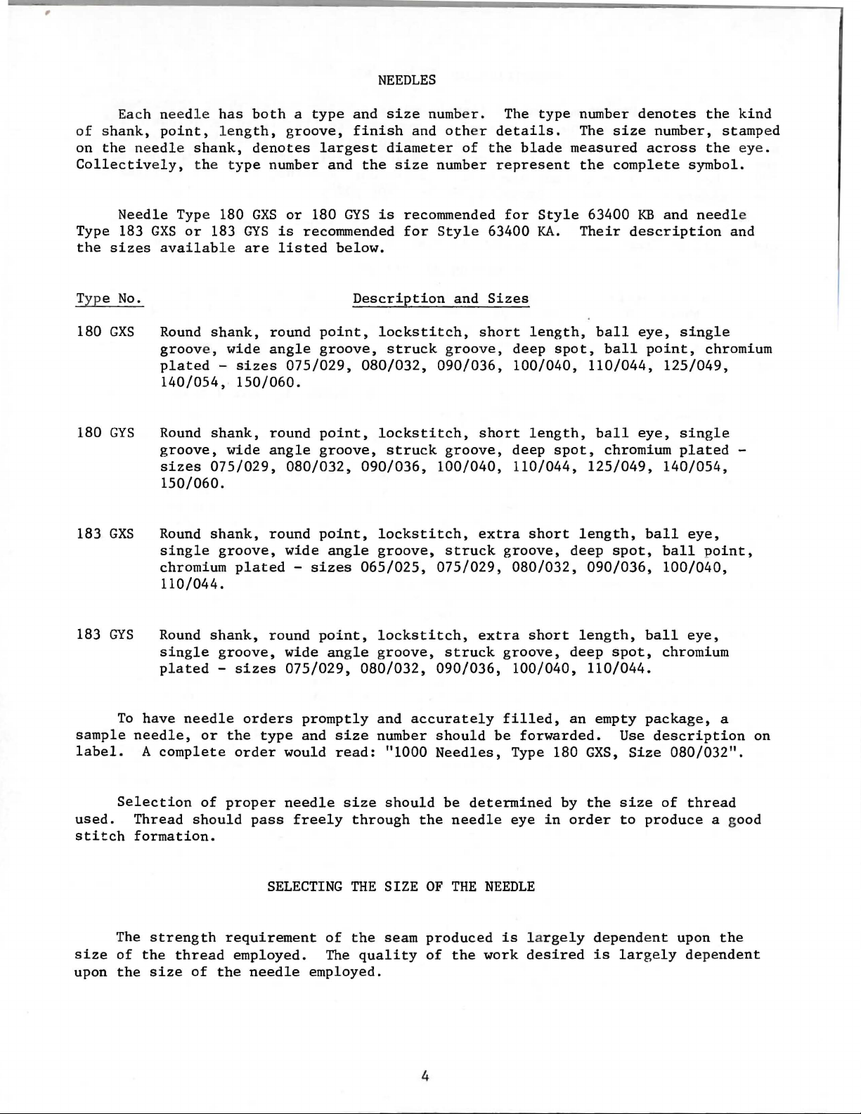
Needle
Type 183
the
sizes
Typ e
180
180
183
No.
GXS
GYS
GXS
Type 180
GXS
or
183
GYS
available
Round
groove,
plated -sizes
140/054,
Round
groove,
sizes
150/060.
Round
single
chromium
110/044.
are
shank,
wide
150/060.
shank,
wide
075/029,
shank,
groove,
plated
GXS
or
180
GYS
is
recommended
is
recommended
listed
round
angle
075/029, 080/032, 090/036,
round
angle
080/032,
round
wide
-
below.
Description
point,
groove,
point,
groove,
point,
angle
sizes
for
lockstitch,
struck
lockstitch,
struck
090/036,
lockstitch,
groove,
065/025,
Style
groove,
groove,
100/040,
struck
075/029,
and
63400
Sizes
short
short
extra
for
Style
KA.
length,
deep
100/040,
length,
deep
110/044,
short
groove,
080/032,
Their
spot,
spot,
length,
deep
63400
ball
110/044,
ball
125/049,
090/036,
KB
description
eye,
ball
eye,
chromium
spot,
and
single
point,
125/049,
single
plated
140/054,
ball
ball
100/040,
needl
and
chromium
eye,
point,
e
-
183
GYS
sample
label.
used.
stitch
size
upon
Round
single
plated -sizes
To
have
needle,
A
complete
Selection
Thread
formation.
The
strength
of
the
the
size
shank,
needle
or
of
should
thread
of
round
groove,
the
order
proper
requirement
employed.
the
wide
075/029,
orders
type
would
needle
pass
SELECTING
needle
point,
angle
promptly
and
size
read:
freely
of
The
employed.
lockstitch,
groove,
080/032,
and
number
size
through
THE
the
quality
accurately
"1000
should
the
SIZE
seam
extra
struck
090/036,
should
Needles,
be
determined
needle
OF
THE
produced
of
the
short
groove,
100/040,
filled,
be
forwarded.
Type 180
eye
NEEDLE
is
l a
work
desired
deep
an
by
in
order
rgely
length,
spot,
110/044.
empty
Use
GXS,
Size
the
size
to
dependent
is
largely
ball
package,
produce
eye,
chromium
description
080/032".
of
thread
upon
dependent
a
on
a good
the
4
Page 5
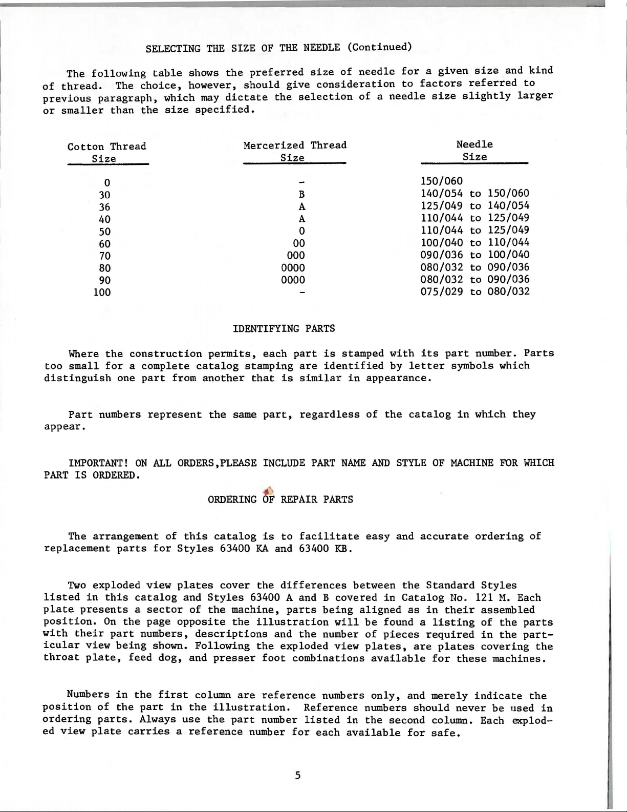
The
of
thread.
previous
or
smaller
following
The
paragraph,
than
SELECTING
table
choice,
which
the
size
THE
shows
however,
the
may
dictate
specified.
SIZE
preferred
should
OF
THE
give
the
NEEDLE
size
of
consideration
selection
(Continued)
needle
of a needle
for a given
to
factors
size
size
referred
slightly
and
larger
kind
to
Cotton
Size
100
Where
too
small
distinguish
Part
appear.
Thread
0
30
36
40
50
60
70
80
90
the
construction
for a complete
one
part
numbers
represent
from
permits,
catalog
another
the
Mercerized
Size
00
000
0000
0000
IDENTIFYING
each
part
stamping
that
is
same
part,
Thread
B
A
A
0
PARTS
is
stamped
are
identified
similar
regardless
in
appearance.
of
the
with
by
150/060
140/054
125/049
110/044
110/044
100/040
090/036
080/032
080/032
075/029
its
letter
catalog
Needle
Size
to
to
to
to
to
to
to
to
to
part
number.
symbols
in
which
150/060
140/054
125/049
125/049
110/044
100/040
090/036
090/036
080/032
Parts
which
they
IMPORTANT!
PART
replacement
listed
plate
position.
with
icular
throat
position
ordering
ed
IS
The
Two
in
presents
their
view
plate,
Numbers
view
ORDERED.
arrangement
exploded
of
parts.
plate
this
On
part
ON
parts
catalog
a
the
being
feed
in
the
the
carries
ALL
ORDERS,PLEASE
of
for
Styles
view
sector
page
numbers,
part
Always
plates
opposite
shown.
dog,
first
in
a
ORDERING
this
catalog
63400
cover
and
Styles
of
the
descriptions
Following
and
presser
column
the
illustration.
use
the
reference
INCLUDE
•
OF
REPAIR
is
to
KA
and 63400
the
differences
63400 A and B
machine,
the
are
part
number
parts
illustration
and
the
exploded
foot
reference
number
PART
N.M1E
PARTS
facilitate
KB.
between
covered
being
will
the
number
view
combinations
numbers
Reference
listed
for
each
in
available
AND
easy
in
aligned
be
found a
of
pieces
plates,
available
only,
numbers
the
second
STYLE
and
accurate
the
Catalog
as
are
and
should
for
OF
MACHINE
Standard
l~o.
in
their
listing
required
plates
for
these
merely
never
column. Each eKplodsafe.
FOR
ordering
Styles
121
M.
assembled
of
the
in
the
covering
machines.
indicate
be
used
WHICH
of
Each
parts
part-
the
the
in
5
Page 6
ORDERING OF REP
AIR
PAR
TS
(Continued)
Sub-a
a
solid
be
furnished
description
34
35
36
37
38
39
In
catalo
parts
ed
tration.
UNION
sidiaries
proved
and
g , no spe
for
in
the
Success
SPECIAL Repair
scientific
durability
sse
mblies,
lin
e bo x on the
for
of the
29480
63458 H
those
the
description,
and
FM
660-360
670 G-18
670 G-23
660-3
cas
cific
vario
in the ope
authoriz
are assured.
which are sold compl et e,
picture
repa i r s , are
main
sub-assembly. Exampl
Rotary
47
es whe
principles, a
re a part
usa
ge
will
us
machines are not the same ,
and,
ration
Part
s as
ed dis
plat
indicated
Tension
Rotary
R
otary
Fema l e
Male Wire Te
Solenoid Lead
i s
common
be me
if
necessary,
US
E G
ENUINE
of
these
furnished
tributor
nd
s . They ar e designed
are
e.
Sol
Sol
Connector Sle
ntion
or
by
separate
Component
by inde
Rel ea
eno
id Cover
eno i
d-------------------------------------
rminal----------------------------
Cover---------------------------------
t o
ed i n
the di
REPAIR PART
machin
by
th
made
with
parts
nting
e :
se Solenoid
-------------------------------
eve, green----------------------
all
of the machin
the
the
ffe
r ence
S
es
can be secur
Uni
on Spe
utmos t precisi
of
their
Asse
description.
spe
cific
will
cial
part,
sub-a
descriptions
mbly---------
usage will
be shown i n the
ed
Corpor
according to the mos t
on. Maximum
sse
es
only
are
mblies,
cov
er ed
Howeve
wit
at i
on,
in
bracket
which
under
-
-------
by
r, when
be me
h ge
nuine
i t s s
eff
-
-----
this
iciency
or
can
the
1
1
1
2
2
1
the
ntionillus-
ub-
ap-
Prices
are
forward
wise
handwheel.
carefully
ing
PREPARATION
attachin
laneous
lead
tension
the
directed.
CAUTION! When
Befor
box, 'the
A bag
wire
Insert
upper
e l e
packed.
g screw, one
attachment
clamp,
releas
fram
are strictly
ed
f.o.b.
A
char
Using both hands
aving factory, each
Aft
followin
OF
MACHINE FOR
of asse
hin
mbly parts, co
to the bed plat
one
e sole
e eyel et
ge
noid
studs
ne t cash
shipping point.
ge
is made
unpackin
er the
g s t eps
extra
scr
ew f
l e
in
(A, Fig.
TERMS
and
subject
Parcel Post
t o
cover the postage
INSTALLING
g ,
DO
NOT
lift machine
on bed ca
machin
should
INSTALLATION
nsis
bobbin,
or synchroniz
ad
wir
hol
es
provided
2
stin
UNION
e and
be f
ting of one
two hi nge s
e,
one s
e .
A)
to
to
chan
shipments ar e
out
g, lif t gently.
SPECIAL
acc
ollowed:
ynchronizer
er lead
for them
top
machine is sewed
ess
ories
f rame
tud
s , two
wire
in
of
arm.
ge without
and insuranc e .
of
box
have been removed from the
thr
ead eye
scr
bracket,
clamp
r e
ar
of
by pla
ews f
and
cloth
notice.A
insur
ed
cing one
off,
let,
or
holdin
one
synchroniz
thr
ee
plat
l l shi
unless
in
spected
one e
g mi
clamps
e .
yel
Assemble
pments
other-
hand
and
pack-
et
sce
ler
for
on
6
Page 7
STANDARD
ACCESSORIES
Included
bobbin
spring,one
four
when
TABLE
the
6347
winder
isolator
setting
TOPS
Lockstitch
bed
228
634
6A
knee
plate
46Q-16
76
also
with
assembly,
lifter
pads
up
is
and
the
machines
FLUSH
each
the
assembly
clips,
machine.
are
with
machine
machine
and
and one machine
installed
the
top
is
mounting
its
in
of
the
a box
rubber
table
machine
of
STANDARD
frame,
pad,bed
rest
tops,
ACCESSORIES-containing
one
oil
positioning
pin.
mounting
These
prepared
drain
parts
with
frame.
jar
spring
are
cut-out,
and
essential
its
and
clamp
screw,
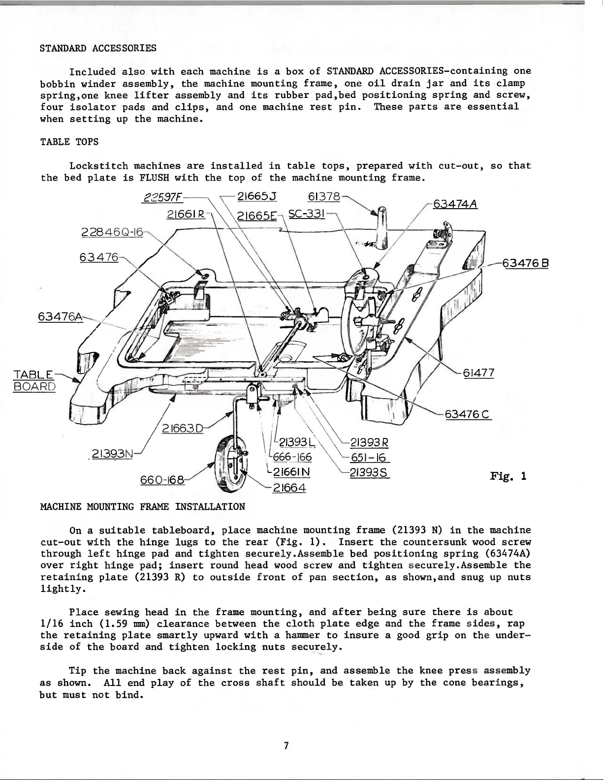
so
that
one
TABLE
BOARD
MACHINE
cut-out
through
over
retaining
lightly.
1/16
the
side
MOUNTING
On a suitable
with
right
Place
inch
retaining
of
left
plate
(1.59
the
the
hinge
hinge
sewing
plate
board
FRAME
tableboard,
hinge
pad
pad;
(21393
head
mm)
clearance
smartly
and
INSTALLATION
place
lugs
to
the
and
tighten
insert
R)
in
tighten
round
to
outside
the
upward
frame
between
locking
machine
rear
securely.A
head
with
(Fig.
wood
front
mounting,
the
cloth
a hammer
nuts
mounting
1).
Insert
sse
mble
screw
of
pan section,
and
plate
sec~~ely.
and
after
to
bed
insure
frame
tighten securely.Assemble
edge
(21393
the
countersunk
positioning
as
shown,and
being
sure
and
the
a good
N)
in
the
wood
spring
snug
there
frame sides,
grip
is
on the und e
about
Fig.
machine
(63474A)
up
1
screw
the
nuts
rap
r-
Tip
the
as
but
shown.
must
All
not
machine
end
bind.
back
play
against
of
the
the
r e
st
pin,
cross shaft should
7
and
be
assemble
taken
the
up by
knee
the
press assembly
cone
bearings,
Page 8
MACHINE
MOUNTING
FRAME
INSTALLATION
(Continued)
Before
lifter
the
maximum
within
raises
BOBBIN
The
located
when
allow
pulley
scribed
BELTS
larged
the
in
belt
These
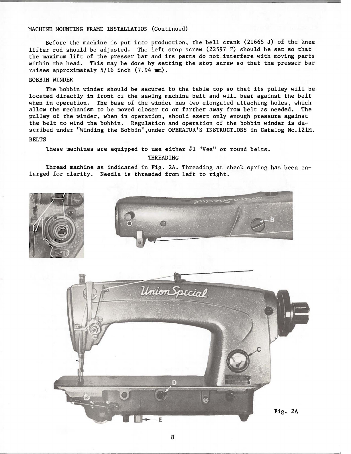
Thread
the
machine
rod
should
lift
the
head.
approximately
WINDER
bobbin
directly
operation.
the
mechanism
of
the
to
under
for
winder
winder,
wind
"Winding
machines
machine
clarity.
be
of
This
in
the
is
adjusted.
the
presser
may
5/16
should
front
The
base
to
be
when
bobbin.
the
are
equipped
as
indicated
Needle
put
into
production,
The
left
bar
and
be
done
by
inch
of
moved
(7.94
be
secured
the
sewing
of
the
winder
closer
in
operation,
Regulation
Bobbin",under
to
use
THREADING
in
Fig.
is
threaded
stop
its
setting
mm).
to
machine
to
or
should
and
OPERATOR'S
either
2A.
from
the
screw
parts
the
the
table
belt
has
two
farther
exert
operation
Ill
Threading
left
bell
do
stop
elongated
"Vee"
to
crank
(22597 F)
not
interfere
screw
top
so
and
will
away from
only
enough
of
the
INSTRUCTIONS
or
round
at
check
right.
(21665
should
with
so
that
that
attaching
its
bear
belt
pressure
bobbin
in
belts.
spring
against
J)
of
be
set
moving
the
presser
pulley
holes,
as
needed.
winder
Catalog
has
the
knee
so
that
parts
bar
will
the
belt
which
The
against
is
de-
No.121M.
been
en-
be
8
Fig.
2A
Page 9
OILING
CAUTION!
reservoir
Fill
oil
is
added
straight
in
dial
a
long
After
when
the
Oil
The
in
clockwise
It
period,
oiling,
must
main
at
maximum
needle
mineral
main
reservoir.
may
quantity
the
direction
direction
is
recommended
Oil
be
reservoir
oil
be
drained
be
lubricated
replace
Fig.
has been
fill
ed bef
at
level
is
of
12
when
in
yellow
of a Saybolt
This
from main
oil
supplied
of
the
decreases
that a new
head
A
drain
ore
plug
needle
band
is
arrow
by
removing
cover
ed from the main re
starting
screw
marked
viscosity
equivalent
reservoir
to
(counterclockwise)
the
machine,
as
to
(B,
is
in
the
hook
flow
of
the
no
further
machine
bute
operation
63400
63400 A
No. 121
additions.
from
the
found
operat
Fig.
yellow
headings
2A)
"LOW".
of
90
to
Union
by
removing
is
oil.
or
one
head
hand
slowly
oil
to
INSTRUCTIONS
The
adjusting
KA
and
and B respectively,
M,
the
ones
in
that
servoir
e .
and
band
cover
can
with
The
marked "FULL".Oil
Use a
to
125
Special
controlled
increases
that
has
and
oiling
for
the
various
then
KB
are
the
instructions
covered
will
catalog.
before
check
plug
indicate
oil
stainless
seconds
specification
screw
by
dial
been
oiling
will
several
parts.
be
expected
FOR
MECHANICS
instructions
the
same
following
in
Catalog
shipment
level
water-white
at
1000
(E,
(D).
the
oil
out
of
the
moving
be
required.
minutes
Full
without
for
as
for
covered
exceptions
that
the
page
and
at
gauge(C);
should
Fahrenheit
No.
Fig.
2A).
Turning
flow
service
parts.
to
distri-
speed
Styles
Styles
in
Catalog
are
different
No.
121
it
can
the
be
175.
the
and
in
for
Run
damage.
and
M,
be
a
The
so
that
presser
tipping
lock
nut
the
lifter
to
the
right
connection
lock
the
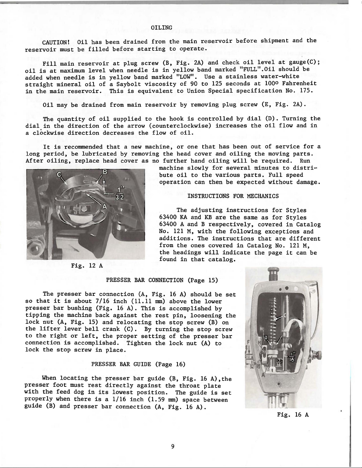
When
presser
with
properly
guide
foot
the
(B) and
presser
it
is
bar
bushing
the
machine
(A,
lever
is
stop
locating
feed
when
bar
connection
about
Fig.
or
accomplished.
screw
must
dog
there
presser
7/16
(Fig.
back
15)
bell
left,
in
PRESSER
the
rest
in
is a 1/16
and
crank
the
directly
its
bar
PRESSER
inch
16
A).
against
relocating
(C).
proper
Tighten
place.
BAR
presser
lowest
connection
BAR
(A,
(11.11
This
the
By
setting
GUIDE
bar
against
position.
inch
CONNECTION
Fig.
16
A)
mm)
above
is
accomplished
rest
pin,
the
stop
turning
the
(Page 16)
guide
(1.59
(A,
of
lock
(B,
the
mm)
Fig.
9
the
the
Fig.
throat
The
space
(Page
should
the
lower
loosening
screw
stop
presser
nut
(A)
16
plate
guide
between
16
A).
15)
be
by
(B) on
screw
bar
to
A),the
is
set
set
the
Fig.
16
A
Page 10
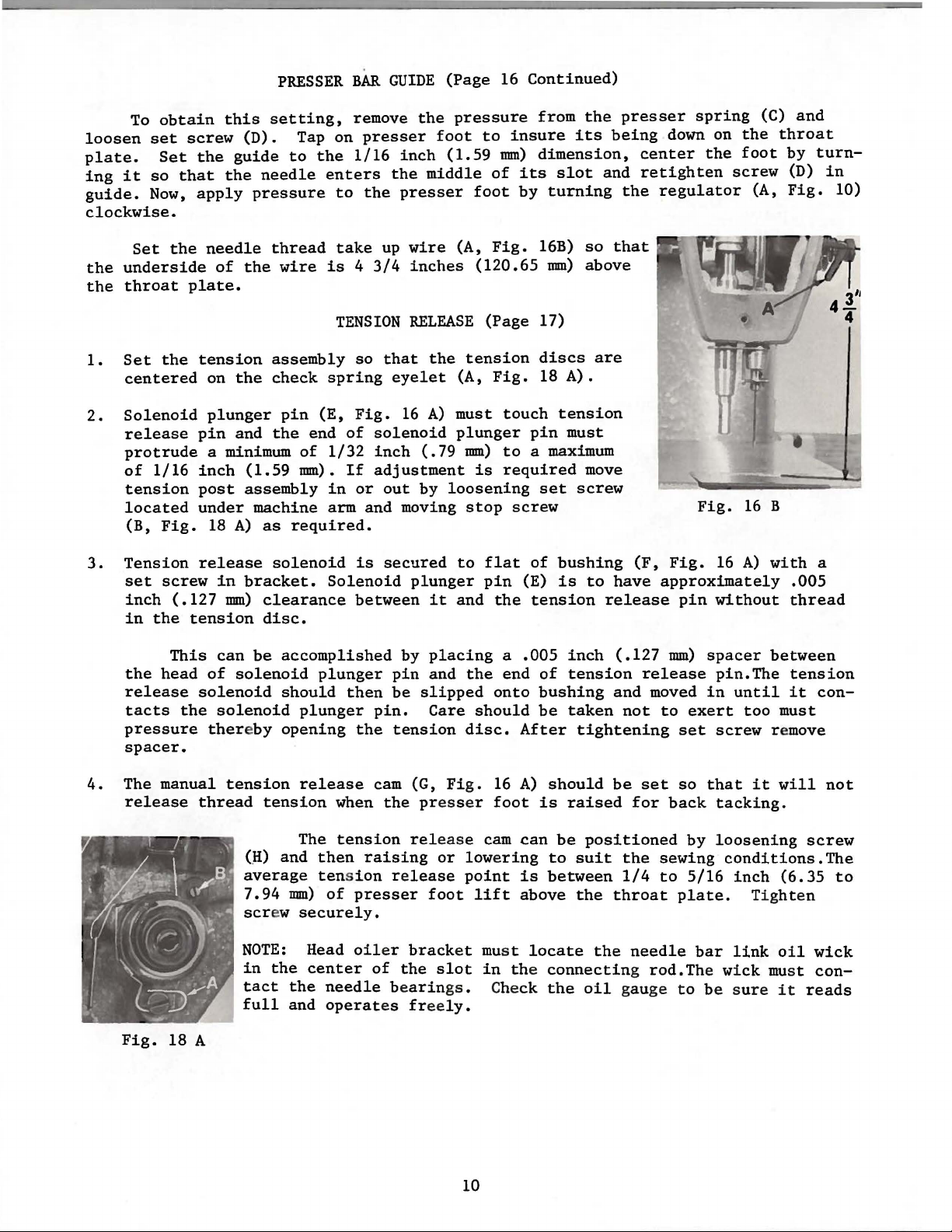
To
loosen
plate.
ing
guide.
clockwise.
the
the
set
it
so
Now,
Set
underside
throat
obtain
screw
Set
the
that
apply
the
plate.
this
(D).
guide
the
needle
of
the
PRESSER
setting,
Tap on
to
needle
pressure
thread
wire
BAR
remove
presser
the
1/16
enters
to
the
take
is 4 3/4
GUIDE
inch
the
presser
up
wire
inches
(Page
the
pressure
foot
(1.59
middle
to
foot
(A,
(120.65
16
Continued)
insure
mm)
of
its
by
Fig.
from
dimension,
16B)
the
its
slot
turning
so
mm)
above
being
and
that
presser
down on
center
retighten
the
regulator
spring
the
screw
(C)
the
foot
(A,
and
throat
by
turn(D)
Fig.
in
10)
1.
2.
3.
Set
the
centered
Solenoid
release
protrude
of
1/16
tension
located
(B,
Fig.
Tension
set
screw
inch
in
the
release
tacts
pressure
spacer.
(.127
the
This
head
the
tension
on
the
plunger
pin
and
a minimum
inch
post
under
release
tension
solenoid
(1.59
assembly
18
A)
in
bracket.
mm)
can
of
solenoid
solenoid
thereby
TENSION
assembly
check
the
machine arm
as
solenoid
clearance
disc.
be
spring
pin
(E,
end
of
of
1/32
mm).
required.
accomplished
should
opening
If
in
Solenoid
plunger
then
plunger
RELEASE
so
that
eyelet
Fig.
or
between
16
solenoid
inch
adjustment
out
and
moving
is
secured
plunger
by
pin
be
pin.
the
tension
the
tension
(A,
A)
must
plunger
(.79
mm)
by
loosening
stop
to
it
and
placing
and
the
slipped
Care
disc.
(Page 17)
discs
Fig.
is
flat
pin
onto
should
18
touch
pin
to a maximum
required
set
screw
of
(E)
the
tension
a
.005
end
of
bushing
be
After
are
A).
tension
must
move
screw
bushing
is
to
release
inch
tension
taken
tightening
(F,
have
(.127
release
and
not
Fig.
Fig.
approximately
mm)
moved
to
pin
exert
set
16
A)
without
spacer
pin.The
in
until
screw
16
B
with
between
too
remove
.005
thread
tension
it
must
a
con-
4.
The manual
release
Fig.
18 A
tension
thread
tension
(~)
and
average
7.94
mm)
scr
ew
NOTE:
in
the
tact
the
full
and
release
The
then
tension
securely.
Head
center
needle bearings. Che
operat
when
tension
raising
of
presser
oil
cam
(G, Fig.
the pres
rel
r e
lease
er
brack
of
the
es free
ease cam
or
foot
slot
ly.
16
ser
foot
lowe
ring
point
lift
et must
in the
10
A)
should
is
can
be
to
is
between
above
locate
connecting rod.Th
ck
the
be
raised
positioned
suit
the
throat
the
oil gau
the
1/4
set
for
back
sewing
to
needle
ge
so
that
tacking.
by
loosening
conditions.The
5/16
inch
plate.
bar
link
e wi
t o be su
it
will
(6.35
Tight
oi l
ck must
re
it
not
screw
to
en
wick
con-
reads
Page 11
ADDITIONAL
INSTRUCTIONS
FOR
63400
KA
and 63400
KB
TRIMMER
follows:
1.
2.
should
tioning
run
positioning
adjustments,
ADJUSTMENTS
Remove
There
adjustment
taking
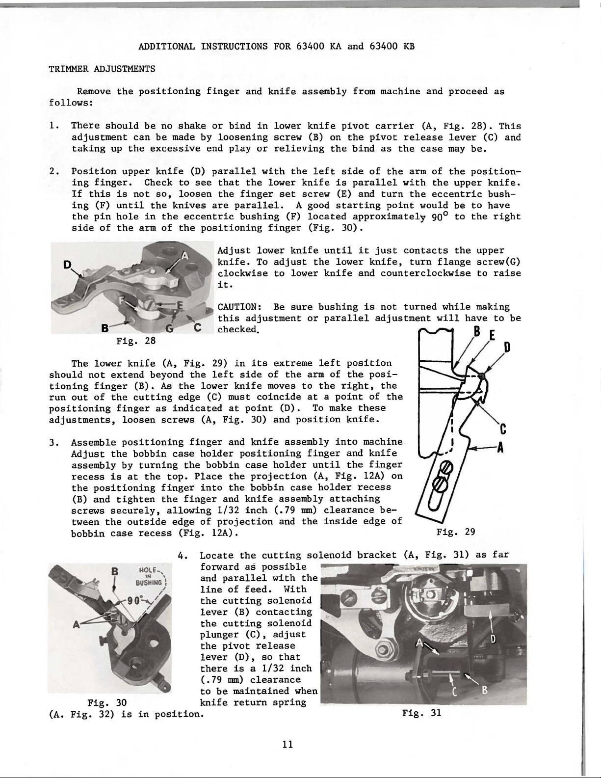
Position
ing
finger.
If
this
ing
(F)
the
pin
side
of
The
lower
not
finger
out
of
the
should
up
the
upper
is
until
hole
the
Fig.
knife
extend
the
finger
loosen
positioning
be
no
can
be
made
excessive
knife
Check
not
so,
the
knives
in
the
arm
of
28
(A,
beyond
(B).
As
cutting
as
indicated
screws
finger
shake
by
end
(D)
to
see
loosen
eccentric
the
positioning
Fig.
the
the
lower
edge
(C) must
(A,
and
or
bind
loosening
play
parallel
that
the
the
finger
are
parallel.
bushing
Adjust
knife.
clockwise
it.
CAUTION:
this
adjustment
checked.
29)
in
left
side
knife
at
point
Fig.
knife
in
lower
screw
or
relieving
with
lower
finger
lower
To
adjust
to
Be
its
extreme
of
moves
coincide
30)
and
the
set
A good
(F)
knife
lower
sure
the
(D).
position
assembly
knife
(B) on
knife
screw
located
(Fig.
or
arm
to
at a point
To
the
left
is
(E)
starting
until
the
lower
knife
bushing
parallel
left
of
the
make
pivot
side
30).
right,
from
machine
carrier
the
pivot
bind
as
the
of
the
parallel
and
approximately
it
knife,
and
is
position
the
posiof
these
knife.
with
turn
point
just
counterclockwise
not
adjustment
the
the
and
(A,
release
case
arm
of
the
the
eccentric
would
90°
contacts
turn
flange
turned
will
proceed
Fig.
lever
may
the
upper
be
to
the
while
have
as
28).
This
(C) and
be.
position-
knife.
bush-
to
have
the
right
upper
screw(G)
to
raise
making
to
D
be
3.
(A.
Assemble
Adjust
assembly
recess
the
positioning
(B)
and
screws
tween
bobbin
Fig.
the
Fig.
32)
positioning
the
bobbin
by
turning
is
at
the
tighten
securely,
outside
case
recess
30
is
in
finger
case
the
top.
finger
the
finger
allowing
edge
(Fig.
4.
position.
holder
bobbin
Place
into
1/32
of
projection
12A).
Locate
forward
and
line
the
lever
the
plunger
the
lever
there
(.79
to
be
knife
and
knife
positioning
case
the
projection
the
bobbin
and
knife
inch
the
as
parallel
of
feed.
cutting
(B)
contacting
cutting
(C),
pivot
mm)
release
(D),
is a 1/32
clearance
maintained
return
assembly
holder
case
assembly
(.79
mm)
and
the
cutting solenoid
possible
with
the
loli
th
solenoid
solenoid
adjust
so
that
inch
when
spring
finger
until
(A,
holder
attaching
clearance
inside
into
Fig.
machine
and
the
12A)
recess
edge
bracket
knife
finger
on
be-
of
(A,
Fig.
Fig.
Fig.
31
31)
29
as
f ar
11
Page 12
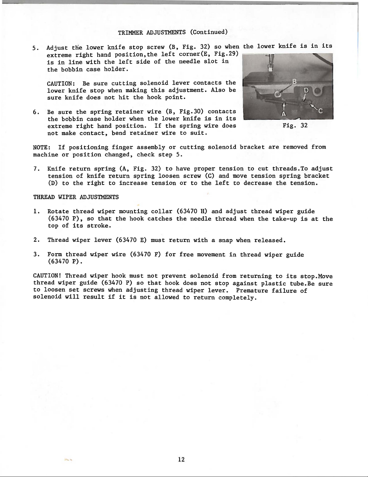
5.
Adjust
extreme
is
in
the
bobbin
t~e
right
line
lower
hand
with
case
TRIMMER
knife
position,the
the
left
holder.
ADJUSTMENTS
stop
screw
side
of
(B,
left
the
(Continued)
Fig.
32)
corner(E,
needle
slot
so
when
Fig.29)
in
the
lower
knife
is
in
its
CAUTION:
lower
sure
6.
Be
the
extreme
not
NOTE:
machine
7.
Knife
tension
(D)
THREAD
1.
Rotate
(63470
top
2.
Thread
3.
Form
(63470
knife
knife
sure
If
WIPER
the
bobbin
right
make
positioning
or
position
return
of
to
the
thread
P),
of
its
wiper
thread
P).
Be
sure
cutting
stop
when making
does
not
hit
spring
case
contact,
spring
knife
right
ADJUSTMENTS
so
stroke.
lever
wiper
holder
hand
bend
finger
changed,
return
to
wiper
that
wire
retainer
position.
(A,
increase
mounting
the
(63470
solenoid
this
the
hook
wire
when
the
If
retainer
assembly
check
Fig.
32)
spring
tension
collar
hook
catches
E)
must
(63470 F)
lever
adjustment.
point.
(B,
lower
the
wire
or
step
to
loosen
return
for
5.
have
(63470
the
contacts
Fig.30)
knife
spring
to
suit.
cutting
proper
screw
or
to
the
H)
needle
with a snap
free
movement
Also
contacts
is
in
wire
does
solenoid
tension
(C)
and
left
and
thread
the
be
its
bracket
move
to
adjust
when
when
in
thread
to
cut
tension
decrease
thread
the
released.
wiper
Fig.
are
removed from
threads.To
spring
the
tension.
wiper
take-up
guide
32
bracket
guide
is
adjust
at
the
CAUTION!
thread
to
solenoid
wiper
loosen
Thread
guide
set
will
wiper
screws
result
hook must
(63470 P)
when
if
adjusting
it
is
so
not
not
that
allowed
prevent
hook
thread
solenoid
does
wiper
to
return
not
from
stop
lever.
completely.
returning
against
Premature
to
plastic
failure
its
stop.Move
tube.Be
of
sure
12
Page 13

ADJUSTING
INSTRUCTIONS
FOR
TELEDYNE
Variostop
AMCO
13
Page 14

ALL
ELECTRICAL
BE
FASTENED
TABLE
BOARD
GAlE
'&N-
RED
WNnE
~;!b:
~
......
226
.p.
6N'~'<
()!;
SECrt0/11
A-A
''
WIRES
SECVRELY
WITH
CABLE
,-.:.-:.--
,~,-
:g:
./
(/(--
:_.._
,.
~
" I
., '\,
'\':, ,,
,,,
::••,;;
I \ Q
,
-:_,.-=
AND
M(ffOR
CABLES
TO
THE
UNDERSIDE
CLAMPS
PROVIDEn
'
~;;----
'•
_ T
___
1::.
- 1 e
;:
l~;;~:::~:~
MUST
OF
THE
.
I
--
t,l
:~
o:
o
:
!::
-~----,.
~~=-
. 0 \
.,
1
J i
),""
.
·.
t
~fh'
---- -
'\
STIIR
WIIS/IE~-=-:_'1/A/
1\
GROIJHD
WIRE
I \
\
Til
BING
REL£,115£ SOLENOID
FROM
SYNCHRONIZER
MOIINTING
RVBBER
BE
SVPPUED
NEEDLE
TENSION
BRACKET
GROMMET
WITH
POSITIONER
TO
THIS
PLANOVRAPH
INSTALLATION
COMPONENT
KB
1\AACHINES
NEEDLE
POSITIONER
OF
PARTS
WITH
SHOWS
TH£
ELECTRICAL
ON
6~'100XA
•800)'P-36Z
.
(
UNION SPECIAL
CHICAGO
ILL
CO
f1POIIAT!ON
INOI
!i
GREEN-
WHITE -
60610
REo
- ,
LIS
"-.
"-.
ENLARGED
FOR
THREAD
A
THE
VI
EW
TFN.SI
ON
CVTTING
OF
THE
ELECTRICAL CONNECTIONS IITT/ICH
RELEASE
SOLENOID
SOLENOID
.
~
AND
THE FOR
Fig.
lA
RET/liNING
SYNCHRONIZER
WIRE.
PLUG
NEEDLE POSITIONER HI
SHOIILO
8£
ALLOW
TO
NEEDLE
BE
PVLLED
FIEST
SO
SET
MACHINE
THE
PRINTED
TO
BAC.X
C.OCI\TE
TREADLE
WI
LL
.
NGE
TO
ANGLE
ro
POSITION.
POSITIONER
IICTLIATING
IN
A
STRA
tN
BRA.CX£T
SHOWN
8£
TILT£D
OVER
ROO
IGHT LINE.
V.S.A.
Page 15

Figure
Assemble
1A.
needle
positioner
motor
to
underside
of
tableboard
as
shown
in
1.
Measure
2.
Disconnect
3.
Remove
CAUTION:
when
NOTE:
being
4.
removing
Dummy
used,
Connector
ponding
be
connected
tween 175-199
line
voltage
unit
bottom
cover
Transformer
or
replacing
connector
to
prevent
and
lead
to
line
to
VAC,
with
from power
from
taps
(A,
connectors
(B)
MUST
any
possible
(C)
must
voltage.
the tap
marked 215-229
remove
TRANSFORMER
CONNECTIONS
voltmeter.
source.
control
Fig.
box.
33)
remain
(B
are
or
on
damage
be
connected
Example:
dummy
If
connector
very
C).
the
transformer
to
unit.
to
line
as
shown.
(B)
flexible
the
proper
voltage
and
and
tap
measures
Should
connect
care
should
be
marked 175-199 when
transformer
219
line
voltage
(C)
to
tap
VAC,
tap.
(C)
measure
taken
not
corres-
should
be-
MACHINE
for
The
the
SPEED
following
desired
"POSITIONING
WORKING
FUNCTIONS
Sewing
Stopping
cond
in
position
pedal.
machine
RPM'S
by
activating
the
first
along
chart
should
speed,
FOR
THREAD
MACHINE
3900
4100
4300
4700
4900
5200
5600
position
with
the
TRIMMING".
SPEED
RPM
RPM
RPM
RPM
RPM
RPM
RPM
the
sewing
by
trimmer
Fig.
be
used
before
heeling
33
for
proceeding
machine
the
and
thread
15
selecting
PULLEY
pedal
pedal
wiper
the
to
adjustments
60
28602
28602 AR-22
28602 AR-23
28602 AR-25
28602 AR-26
28602 AR-28
28602 AR-30
forward
to
the
is
correct
CYCLE
SIZE
(U.S.
AR-21
from
neutral
acheived
motor
ONLY
the
position.
by
pulley
described
PART
NO.)
normal
position.
heeling
size
under
The
the
se-
Page 16

WORKING
FUNCTIONS
(Continued)
CONTROL
PANEL
1 -
5 b1 b2 b3 -
Control
Actuating
Synchronizer
Clutch
Accessory
Thread
Thread
Foot
24
lift
vdc,
box
shaft
and
Connections
trimmer
wiper
9 &
O.SA
receptacle
brake
1 & 2
1 & 3
10
6 &
10
(10=+)
P1 -
Potentiometer
P2 -Potentiometer
P3 -Potentiometer
P6 -Potentiometer
P7 -Potentiometer
Both
P6
and
P7
are
POSITIONING
Independent
(Fig.
functioning
INTERMEDIATE
They
the
be
duced
34)
P2 -Intermediate
can
speeds
adjusted
P3 -
to
RPM'S
should
of
thread
SPEED
be
either
leaving a larger
according
Maximum
that
of
Fig.
for
for
for
for
for
accessible
FOR
of
motor
be
adjusted
RANGES
condensed
speed
step
34
setting
setting
limiting
adjusting
adjusting
THREAD
rpm
trimmer
speeds 2 to
to
the
limitation.By
9.
Further
positioning
intermediate
by
TRIMMING
or
to
mechanism.
or
rpm
difference
sewing
top
speed
thread
presser
removing
pulley
200
expanded.
adjustment
diameter,
RPM.
9.
These
requirements.
turning
speed
speeds
tension
foot
cover
Setting
speeds
P2
turned
between
P3
is
release
lift
on
adjustable
beyond
against
then
right
cannot
step 9 and
side
this
be
to
the
left
the
controlled
via
left
of
control
potentiometer
speed
independently
stop
step
stop,step
by
will
10.
the
lead
will
This
setting
box.
Pl
to
adjusted.
condense
should
10
is
of
mal-
re-
P2.
NOTE:
operator
Maximum
training,
speed
not
adjustment
for
continued
is
recommended
use.
only
16
for
exceptional
cases
such
as
Page 17

THREAD
TENSION
RELEASE & PRESSER
FOOT
LIFT
Adjustment
eter
P6
until
ometer
wiper
NOTE:
presser
ing
Place
chronizer
plate
screws
(Position
NOTE:
the
Adjustment
has
Attach
from
rubber
over
(Fig.
P7
This
foot
in
These
34).The
trim
(Fig.
returned
adjustment
lift
the
tension
grommet
onto
grommet on
synchronizer.
of
the
settings
for
the
length
potentiometer
knife
for
synchronizer
the
has
the
presser
34)
and
should
to
its
is
kit.
release
over
adaptor
synchronizer
synchronizer
are
of
thread
should
finished
rest
only
INSTALLATION
mounting
solenoid
the
of
Tighten
SETTING
made
cutting.
foot
signal
be
adjusted
position.
necessary
to
end
of
handwheel
bracket
screws
on
handwheel
THE
looking
tension
be
set
after
so
that
for
machines
OF
SYNCHRONIZER
bracket
the
synchronizer
assembly,
holding
SYNCHRONIZER
from
back
to
adaptor
the
(63495
of
stabilize
release
so
that
trimming
the
R),
machine,
mounting
aligning
the
synchronizer
is
right
is
controlled
the
is
foot
equipped
of
end
lifts
ground
as
bracket.
the
same
no
importance).
of
via
potentiom-
tension
controlled
with a pneumatic
wire,
shown
slot
and
machine.
discs
after
clamp and
in
Figure
Assemble
of
tighten
bracket,
via
the
front
the
securely.
are
open
potenti-
thread
tub-
lA.
syn-
bearing
two
set
HEEDLE-DOWN
With power
taking
its
NEEDLE-UP
time,
opening
NOTE:
POSITION
POSITION
off,
with
is
All
should
the
needle
centered
printed
handwheel.
turn
face
the
on
in
the
words
away
handwheel
upstroke.
synchronizer
on
discs
from
in
Rotate
Fig.
operating
the
needle-down
head.
35
direction
until
disc
(A,
hook
Fig.
is
at
35)
loop
until
With power
is
1/8
(A,
Fig.
(C)
with
opening
inch
36)
needle
is
off,
(3.18
in
the
in
centered
turn
mm)
hook
the
in
the
before
deflector
up
position.
the
synchronizer
handwheel
top
dead
(B)
Rotate
in
operating
center,
aligns
head.
OR
~h
the
direction
leading
front
needle-up
17
edge
edge
disc
until
of
the.first
of
positioning
(D)
until
thread
take-up
screw
its
finger
smaller
Page 18

NEEDLE-UP
TRIM
POSITION
(Continued)
Fig.
D
A
36
With power
the
hook
edge
until
synchronizer
contact,
NOTE:
(C)
in a clockwise
check
CAUTION:
disc
thread
of
positioning
the
recheck
If
needle
NEEDLE-UP
If
must
be
off,
trailing
head
machine
marked
turn
deflector
finger
edge
(Fig.
NEEDLE-UP
thread
POSITION.
tail
direction,
is
equipped
ELEC
A
the
(A,
(B),
of
its
37).
POSITION.
is
handwheel
Fig.
37)
with
needle
smaller
Since
not
gradually,
with
the
long
an
in
operating
is
1/32
inch
on
upstroke.
opening
"needle-up"
enough
until
electric
proper
ClD
direction
(.79
coincides
and
for
proper
tail
"Klipp-It"
mm)
Rotate
with
"trim"
starting,
length
thread
until
to
the
discs
the
the
left
is
triunner,
tip
of
rear
of
trim
disc
corner
are
in
rotate
acquired.
finger
the
(C)
of
constant
trim
the
disc
Re-
trim
c
of
rear
the
t
1/32"
(.
79mm)
Fig.
37
18
Page 19

Both
Needle
thread
threads
thread
cut
Condition
not
cut
not
cut,
but
bobbin
TRIMMER
Circuit
not
Solenoid
Lower
enough
Lower
wipes
Lower
slip
Spring
ing
catching
Lower
enough
Hook No. 29474 R
TROUBLESHOOTING
Causes
breakers
open
not
working
knife
not
to
the
knife
too
threads
knife
when
retainer
position
knife
to
right
too
case
does
off
bobbin
right
behind
knife
control
in
moving
far
forward,
knife
back,
far
returns
wire
not
holder
move
not
or S used
far
contact-
when
box
threads
in
far
Reset
Check
Make
continuity
Reset
Relocate
nicks
Relocate
Bend
spring
suit
.
Adjust
setting.
solenoid.
belt
off,
solenoid
tacting
position
Use
only
Cures
circuit
lead
stop
knife.
radius
on
knife
stop
Check
Operate
pivot
stop
solenoid
No.
breakers
connections
check
screw
Check
retainer
screw
to
position
to
machine
determine
lever
screw
if
29474 T hook
for
wire
standard
if
is
and
then
necessary
to
of
with
con-
re-
Bobbin
thread
Lower
the
way
Needle
random
Needle
Bobbin
NOTE:
not
thread
cut
does
knife
thread
lengths
unthreads
thread
Refer
information
breaks
to
not
tears
of
when
Amco
cut,
but
return
and
leaves
starting
starting
Variostop
regarding
needle
all
tail
Catalog
the
needle
Bobbin
in
bobbin
Needle
or
big
Not enough
return
rough
tension
Lower
knife
Too
much
tension
needle
pull-off
Tension
Needle
ed
properly
Needle
big
Bobbin
Overspin
Too
much
tension
Sharp
edges
knife.
are
the
furnished
positioner
thread
case
hole
has
spring.
thread
on
knife
and
thread
at
disc
thread
hole
thread
on
knife
(Front,
T.c.s.
with
not
throat
in
been
altered
tension
Dense
will
knife
rubbing
return
excessive
eyelets
cone
not
take-up
at
top
in
throat
too
bobbin
return
on
T.C.S.
point
of
each
and
electrical
threaded
on
material
require
return
hook
open
of
short
thread
and
lower
needle
plate
lower
more
spring
point
spring
friction
and
in
not
position-
stroke
plate
spring
of
lower
back
knife)
positioner
circuitry.
thru
is
knife
thread
is
too
and
in
too
edges
Thread
Use
throat
needle
Increase
return
to
the
Raise
Unthread
the
right
Decrease
turn
thread
Check
solenoid
tion
Check
take-up.
inch (3. 18
upstroke
Use
throat
needle
See
bobbin
Check wind
bobbin
Decrease
spring
bracket
Stone
lower
back
lower
for
guardian
properly
hole,
spring
right
lower
spring
pull-off
setting
of
this
position
Must
hole,
in
tension
slightly,
to
sharp
knife.
edges
knife)
plate
with
if
available
tension
by
knife
some
of
of
the
tension
slightly.
at
of
and
electrical
solenoid
of
be
within
mm)
of
plate
with
if
available
thread
of
bobbin
bobbin
case
on
by
the
left
edges
(Front,
are
the
maintenance
smaller
on
lower
knife
moving
on
bracket
eyelets
the
tension
tension
needle thread
the
breaks
of
knife
Check
cones
top
smaller
and
holder
knife
moving
T.C.S.
point
T.C.S.
and
post.
re-
release
opera-
1/8
of
fit of
return
and
of
other
to
its
of
19
Page 20

Page 21

ADJUSTING
INSTRUCTIONS
FOR
ELECTRO
DRIVE
QUICK
and
STOP
NEEDLE
POSITIONER
21
Page 22

COCOO·SSG.
<:l.AW'
fO~
\o'()"(QR
J'"M<4'
fll~E
6aM'D
\
<-LJ<M,..
\{
N
N
65?v·2#
1
rZN$
t:).r
A'tl'
i>hH4'KJ
~~Fw.s
II
29~
q,
.6V
RJI'r
ECX
SC333A
SC!i'EW
9!l304=-;p
~E
iO
~fl-.l,/ol,u.tqA!S
.M£Sifi~.EO
.IYI/71'
I \ \ . .
?>?>&-2'=>1
N0TI:
BIJXILIARV
CONTROL
WITHOUT MOUNTING
BOX,•
AVAILI\'BLE
CUS1'011ER
PANEL,
998-2.98
REPAIR.
FOR
IS
U H
1-/
IACHIN6Q£WC£----~
TO
B£
CCWN~CT£0
TO
PINS7f8
-J
.3
F)
OIA.
Dli'IL
L
-i_aA. # DC£P
(F"Oii?
EXPOI?I
&.·472
p~
10
•HS·~
.
fr
FOil!
I
,~PIIIfi>
,;,
938-Z70
IS
/£X71?A
/M:HIN6 Ll€Vtt'£
AVAILABLE
.sENDi-CIIARt;~)
TUB/Nf!i
lii'EL£A:3£
.376A
Pt.IIG
15
l/l'llll
SCQ£W
ALL
'ROU~D
71-1
02/LLED
G»>POIIIENT
/1&£
N££DL£
TRIM
FaE'
CAaLE
/S
MEH
ONLY)
CIISroME~r
*~=~·PARTS
I
CAUTION
.:SYNCHRONIZ£.@
PEP
PUS\'\
'39578
f:'fii>OM
TE:.NSION
SOL£NOI
CLAHPS
1\
U..tl
PLAN06/i!APH
HOLES
POSI770NEE: 4
CIRClii
A
~!3400
AIXTUS77N~
USE
WOOt>
C:.C!;!E'NS
AND
RI/RTS
TH'r'-N11800.ST-36Z
DE!
NOTE
:
SJTiQI.l
e.
~
C:.C
~SSA
SHOWSDIHENSIONSf:'OE!
INSTALLATIONS
ON
Qli/CK-STOP
KLIPP-IT
~!3900
/NCLUO£D
CHECK
SETTIN6
.SUP!i?IN~S
INSTPUCTICNS.
Of:'
n-IHEAD
MACHIN£.
IN~~
OF
.A.S
INS7i4LLATION
I.
INSTALi
ALJXIL/AI7Y
Z.
PLACE
MACHIN£.
Af:'TE!i?
INSTALL/N~
ACCOE?DIN6
FU!i?NISI-IED
3.AFTEE'
7Z>
ACCORDIN4
TtONS,
L:LECTRICAL
I.
AND
i?.
S£CUii?IN4
TH£
HAND
~
a)
~K£
7l:)
77£
WI~
RE:CCP7ill£J.£
b) E'I.JN
WII?ES
8:l4.e'O
AT174CJI
WHITE(CLEAPJ
71-1£
HA~NI!SS
t:,,eEEN
Pt.ACE
/.~OLE
AI.IX!Ll"'IIZY
FOR
EXPOI:'T"ONI..Y- 1/SE
MOUlT
SH/111
~q._u_§E
IN
Pl.A(:£
OE'fLJ. NE.W
3~
FROM
WI~
RIGHT
U.SIN4
.£AR6£
71-1£
QUCK-STOP
CONTROL
TO
WITH
WHEEL
TO
·
TJ.I.C Fl:JLLt:::J#VI
CONNECTIONS.
77-1£
£NO
ANO
PLU4
niE
TENSION
1t>
711£
7HROU6H
Til£
7WO
SC/t.£NOI
Jl-"
£
~¥/-liT£
-f-IJE
,t;!£CFPrA~LE
.;3495F
CY
IWCJN<13~
li?EST
LIP
n-1/t?EAD
Ql4
.
845£-
PROCEDUI?E
MOlDR'
AS
IND!CAn:D.
TIHING
INSTE?UC-
N4
TWO
PLU6
ATUIOI£.0
THE
Fl:JIJe
SOLENOID
OF
/A.
711£
F7C'OftiT
7HC
l.'-0-4ZO
t'4.e£EN
tr&) lfN O
THE
rJ.Uf
BDJ<'.
NOZ9480FV
BED
SCE"n.t.S
IIPPE'OX-
/..IN£
,ONLY
WITH
AND
TH_E
HOLE,
WHEN
80><'
IN
lJfE
TA8/..£/3CIAICO
T/4£
714£
THE.
F1:>Uii?
OF TilE SYNCJ.IIi?ONIZE/i?
IN
TUO
SI.E.EVED W/E'£3
CONT~DL
H/N6E
ACCESSOE'i£S
INST!i?UCTIONS
71-IE
MACHINE..
TI-lE .SYNCHE'ON/Z£1?
ANO
ADJ7J5TIN4
P/i3:JNC.
IT
INTD
TI-lE /'10TCRFNV£L
EE:LEASE
UNO~
THE ~ D
6I!£EN AND
DS
70
INDICATED
To
w u
PLLA$ /NT()
TWO
PIN
DF 0
:!.TANO
KIT
BETW£EN
HCL£
".
PIN
IN
~Z596.5CaWS
R4N'IN
IT
HOLE
TWO
ro
:51'1.
.
;g~OL<N<>O
Fii!O/>I
CUTTIN6
}
.SOL.£NOIO
LI
N /
ON
CH!CA40,
.sPECIAL
ILL!
NaS.
CoRPORATION
60610
,
U.~
.
Fig.
lB
-•'lltO (51
11'
CYf
EYPORT
61i0:379
8COQT·3·2. OR EXPORT
PIIII'C.IAf)
!137<i-2M
(fOCIA
PQINTE:D
PIN
FOR
PLU6)
IN
USE
OR
FOR.
!1976-200•
U.5.A.
OH
9S7G
USE
SOGIST-31>2.
-210,
ON
Page 23

The
synchronizer
hub,
band
anism".
position.
"needle-down"
(A,
Band (B)
Band (D)
Fig.
38)
is
adjustable
is
position.
is
composed
is
also
SYNCHRONIZER
of
three
fixed
on
the
by means
adjustable
ADJUSTMENTS
slip
rings
synchronizer
of
by
screw
means
(C) and
of
and
and
screw
four
carbon
controls
controls
(C) and
brushes.
the
"cutting
the
"needle-up"
controls
The
mech-
the
Assemble
synchronizer
synchronizer
be
moved
NOTE:
on
the
freely.
The
downstroke,
the
brush
to
the
hub,
following
holder
handwheel
band
(A)
settings
with
SETTING
at
the
and
adapter.
this
should
hook
THE
SYNCHRONIZER
bracket
Do
time.Loosen
be
made
point
at 9:00
c
to
not
the
with
1
(47.
machine
tighten
screw
the
o'clock.
11
7/8
82mm)
as
screws
(C)
so
motor
r
I
shown
(E,
that
switch
19/32"j
32,54
f_t.u
LP.adtng
Non-Cond.
''B-1"
rr
bands
mm)
7/16"
Edge
Seg.
in
Fig.
Fig.
turned
mm)l
Of
38)
(B
off,
lB and
in
the
and
D)
needle
TOP
EDGE
the
may
Figure
sional
of
the
used
contact
as
to
the
the
the
(Fig.
follows:
for
operator's
machine,
39
is
relationships
synchronizer.
making
sketch
39)
is
over
made
in
position
placing
the
Fig.
these
FLUSH
38
provided
for
A
Fig.
the
top
to
setting
plastic
settings
39.
Visualize
while
top
of
the
with
the
shown
rule
as
seated
edge
bands
edge
dimen-
the
bands
may
compared
from
at
of
sketch
until
of
the
be
23
brushes
(NOT
''A-l"
THE
Fig.
BRUSH
_l
39
HOLDER)and
(84.
3
5/18"
14mm)
proceed
Page 24

SETTING
THE
SYNCHRONIZER
(Continued)
Rotate
til
the
inches
by
screws
Rotate
NON-CONDUCTING
ING
BAND
TRAILING
es
(84.14
WHILE
With
tween
has
now
Each
NEEDLE-DOWN
With
ing
direction
handwheel
approximately
(D,
Fig.
hub,band
LEADING
(47.62
(E).
band (B,
(B)
EDGE
mm).
HOLDING
bands
the
"cutting
been
of
the
in
38)
mm).
segment
IN
of
acquired.
the
SETTING
power
until
the
5/64
should
(A,
EDGE
of
Secure
Fig.
aligns
THIS
(A, B and
POSITION,
its
NON-CONDUCTING
BANDS
mechanism",
settings
off,remove
the
operating
inch
be
on
Fig.
38)
its
CONDUCTING
the
synchronizer
38)in
with
(B
and
D)
set
can
be
the
needle
direction
(1.98
mm).
brush
of
the
synchronizer
segment
the
operating
("B-1",
rotate
D)
to
"needle-up"
checked
has
(F).
band
segment
IN
THIS
their
throat
reached
until
At
this
aligns
to
the
direction
Fig.
(D)
aligns
POSITION,
respective
position
as
follows:
plate
its
the
point,
handwheel
39) 7 I
in
the
with
tighten
positions,
and
and
turn
lowest
hook
point
the
in
the
operating
with
16
operating
position;
NON-CONDUCTING
("A-1",
until
inch
("C-1",
the
the
has
Fig.
adapter
the
LEADING
(11.
11
direction
Fig.
screw
"needle-down"
handwheel
(C)
the
continue
passed
direction
39) 1
in
this
position
EDGE
mm)
.
HHILE
until
39)3
relationship
5/16
securely.
position
in
the
to
the
needle
segment
turn
un-
7/8
of
its
HOLD-
the
inch-
be-
operat-
the
by
of
band
NEEDLE-UP
With
point
EDGE
brush
must
Adjustment
motor
have
.
firmly.
rotated
arm
flywheel
for
is
of
the
holder
Clutch
be
taken
and
been
If
the
When
freely
is
lifted
Inching
location
SETTING
the
power
at
9:00
NON-CONDUCTING
(G)
free
can
the
provided
clutch
in
disc,
Device
and
off,
o'clock,
by
approximately
play
to
assure
be
accomplished
clutch.
for
arm
lifting
without
excess
which
No. 998-270
Fig.
should
is
turn
that
Two
this
is
the
the
of
clearly
40
with
segment
normally
.012
purpose.
in
braking
clutch
clutch
.010
for
wiring
the
handwheel
needle
of
1/4
CLUTCH
the
clutch
by
removing
inch
position,
arm, a
or
inch
recognizable
INCHING
is
an
connections.
in
the
on
its
downstroke.
band
inch
ADJUSTMENTS
be
(.305
brake
(.254
extra
(B)
(6.35
.020-
is
never
spacers
mm)
position
engaging
mm),
when
SWITCH
send
should
.028
and one
the
the
and
operating
have
mm).
inch
engaged
as
required,
"V"
belt
at
which
must
clutch
turning
charge
At
(.508-
at
.020
be
the
direction
this
passed
any
inch
pulley
the
"V"
obtained.
disc
"V"
item.
point,
the
.711
time
with
located
(.508
must
belt
should
belt
Refer
until
the
top
of
mm),
between
mm)
be
braked
pulley
If
the
engage
pulley.
to
Fig.
the
LEADING
the
but
the
brake.
spacers
can
clutch
the
hook
care
the
be
lB
24
Page 25

If
pressed,
treadle
without
the
needle
the
pushbutton,
the
cutter
is
heeled
trimming.
out
of
band
while
This
the
which
of
the
enables
work,
PUSHBUTTON
is
mounted on
the
synchronizer
pushbutton
the
operator
but
without
FUNCTION
the
is
is
depressed,
to
having
front
trimmed
edge
interrupted.
the
readjust
needle
or
the
of
the
Therefore,
realign
threads.
table
will
board,
when
position
the
garment
is
the
up
de-
with
HOTOR
Before
main
ing.
designed
motor
supply
The
200
volts,
Stop
Catalog.
The
direction
sible.This
ing
the
plate,
required,
CLUTCH
Adjustment
ed
on
the
arm,
which
should
treadle
screw
ion
auxiliary
rection
the
setting
be
(A,
until
set
AND
CLUTCH
starting
voltage
terminal
to
accommodate
three
clutch
of
the
can
three
in
to
screw
of
socket
reposition
retighten
AND
MICRO
right
actuates
made
"rest
Fig.
the
switch
control
the
counterclockwise
the
ARM
to
operate,
with
strip
phase
arm
pitman
be
of
hand
as
position".
41)
position
switch.
A.C.
should
accomplished
head
screws.
SWITCH
the
micro
side
the
follows;
in a clockwise
closes
starts
ADJUSTMENTS
check
the
motor
of
the
connection
See
point
rod,
when
screws
the
clutch
ADJUSTMENTS
switch,locat-
of
the
magnetic
with
Turn
and
running.
where
motor
in
by
the
the
the
1/2
wirfor
Quick
the
pos-
loosen-
on
arm
clutch
clutch,
the
direct-
Now,
auxiliary
to 1 complete
is
the
the
as
set
turn
the
set
control
revolution
screw
stops
Fig.
in a counterclockwise
running.
to
40
obtain
Continue
the
correct
to
di-
turn
Fig.
41
25
Page 26

CLUTCH
AND
MICRO
SWITCH
ADJUSTMENTS
(Continued)
Adjustment
clutch
a
short
Heel
position,
clockwise
treadle
wise
position,
as
micro
switch
automatic
present
will
arm,
Be
sure
treadle
However,if
However,if
to
A method
follows:
If
the
switch
If
the
remains
Screw
affect
which
that
distance
and
this
until
is
heeled,
the
point
and
open
for
down
is
up
only
(C,
Fig.
presser
time.
the
of
the
actuates
all
connections
and
stop
needle
the
needle
indicates
micro
the
needle
this
where
when
making
only
open.
It
function
position
closed
position
41)
foot
should
micro
with
should
travels
micro
switch
only
indicates
the
the
this
when
is
for
lifting
be
of
switch,
the
up and
are
treadle
position
right
switch
is
closed
positions
micro
micro
treadle
unit
treadle
is
remembered
screw
switch
a one
is
desired,
desired,
adjustment
mechanism.
(B).
located
trim
plugged
in
up
through
is
open.
when
down
switch
is
is
heeled.
position,
is
in
turn
of
not
to
the
position,
into
rest
position.Needle
and
trim.
the
Screw (B,
treadle
and
is
closed
turn
screw
the
rest
screw
the
micro
This
assist
to
turn
rear
on
should
the
main
down
position
is
in
will
open.
positioner
not
Turn
when
position.
this
the
(B,
Fig.
(B)
counterclockwise
switch
is
screw
the
underside
be
made
control
should
Fig.
41)
rest
position.
position
screw
treadle
(either
41)
which
not
available
all
of
as
follows:
panel.Run
position
to
the
up
should
up
and
(B)
counterclock-
is
in
up
or
clockwise
until
activates
at
the
way
the
machine
and
be
turned
trtm
the
down)
until
an
the
in
as
down.
trim
when
rest
is
micro
it
Screw (D,
treadle
This
(E,
Fig.
Position
up
to
sitioning
Machine
Speed
5500
5000
4500
4000
3500
to
give
the
unit
41).
you
speed
Fig.
41)
rest
position
incorporates
speed
the
is
Cycle
should
correct
not
60
50
60
50
60
50
60
50
60
50
should
maintained,
have
after
FUSING
a 2
1/2
SYNCHRONIZER
be
kept
pulley
SPEED
Amco
only
it
has
THE
POWER
AMP,
between
sizes
trimmer
Part
250 V
for
VS
Motor
Number
634
643
632
640
630
635
626
632
623
626
enough
been
ADJUSTMENT
180-200 R.P.M. The
CYCLES
tension
heeled.
PACK
fuse
50
and 60
may
not
Pulley
on
as a safety
cycle.
work
correctly.
the
Quick
Pulley
for
spring
feature
following
If
to
180-200
Stop
Part
180-200
995-254-37
995-254-37
995-254-42
995-254-42
995-254-46
995-254-46
995-254-50
995-254-50
995-254-61
995-254-61
return
located
chart
R.P.M.
Positioning
Number
R.P.M.
is
the
at
set
po-
26
Page 27

QUICK-STOP
TROUBLESHOOTING
NOTE:
If
the
Condition
does
Unit
Machine
position
treadle
stops
only
in
position
~lachine
after
will
sewing
continues
at
inching
difficulties
positioner
not
position
in
up
with
rest
not
stop
and
to
rotate
speed
in
on
needle
the
motor
Blown
Synchronizer
connected
Synchronizer
connected
Micro
arm
not
Microswitch
side
adjusted
positioning
control
Causes
fuse
plug
leads
to
plug
switch
in
opening
on
of
clutch
properly
are
panel
not
clutch
right
arm
encountered,
only.
not
not
check
circuitry
Cures
Replace
Plug
into
main
Check
between
fuse
in
synchronizer
the
right
motor
control
leads
brush
continuity
plug
Turn
motor,
direction
machine
after
Adjust
of
is
arm
the
setscrew
located
to
the
in
rear
in a clockwise
until
stops
sewing.
screw
clutch
arm
on
counterclockwise
until
then
machine
make
one
socket
holder
which
the
clutch
of
the
needle
right
in
a
direction
stops,
more
for
plug
of
panel
and
the
down
side
and
turn
Unit
does
positions
Solenoids
energize
Machine
only
Unit
positioner
trims
out
Too
and
of
much
needle
clearance.
not
up
do
stop
thread
pull
trip
not
down
up and
lever
but
pulls
Microswitch
Defective
Blown
control
fuse
panel
Synchronizer
adjusted
properly
Relay 4 not
due
to
bent
Microswitch
arm
closed
Defective
Tension
Ball
lever
the
opening
head
worn
sliding
sluggish.
defective
push
button
in
main
not
energizing
contacts
in
clutch
at
all
times.
microswitch
late
screw
out,
of
or
the
bore
sleeve
pull
of
Replace
Replace
Replace
microswitch
push
fuse
Readjust
instructions
Reshape
contacts
3
Replace
Relay
Replace
Renew
sliding
grees
sleeve
microswitch
4
is
board
ball
sleeve
for
has 3 bores.
button
synchronizer
of
sticking.
head
screw
around
new
bore.
per
Relay
or
120
Sliding
turn
de-
27
Page 28

...
1
, I
)
I
I
I
Page 29

ROTATING
HANDWHEEL
HOOK
ASSEMBLY,
ASSEMBLY
AND
NEEDLE
POSITIONER
MISCELLANEOUS
ASSEI1BLY,
PARTS
R
ef.
No.
1
2
t -
3
4
5
6
7
8
9
10
11
12
13
14
15
16
17
18
19
20
21
22
23
24
25
26
27
28
29
30
31
32
33
34
35
36
37
38
39
40
41
42
43
44
45
46
47
48
49
50
51
52
53
54
55
56
57 22766
58
29474 T
63913 A
63913 B
63913
61414
22716 B
22564 E
61216 N
61216
61415 A
61415
61212
63414
22716 A
63410
22569 H
63408
22716 H
61411 A
63421 A
61321 L
61421 E
22574 c
61421
63421 c
22894 v
63495 D
63459 A
22570
63492 E
63492 D
63458 B
22513
63458 D
63402 B
61273
63432 E
22874 J
63439 A •
63439 B
63982 c
22571 G
22841 K
41071 G
HS82
63970 A
*
*
*
Refer
to
if
needle
insert
available.
positioner
Part
No.
c
BC
660-254 D
J87 J
660-356
376
A
660-352
73
c
660-219 B
91
A
18-768
800 XT-362
BOO
YP-362
sheet
Also
and
Description
Rotating
Handwheel
Screw,
Synchronizer
Synchronizer
Screw,
Tension
Presser
Bushing,
Tension
Tension
Screw-------------------------------------Tension
Bed
Feed
Throat
Oil
Drive
Screw,
Feed
Feed
Oil
Plug
Stud
Presser
Nut----------------------------------------------------------------------
Screw---------------------------------------------------Screw--------------------------------------------------------------------
Needle Thread
Needle
is
Needle
with
refer
needle
to
electrical
Hook
Bobbin Case
Bobbin Case
Bobbin--------------------------------------------------------------Bobbin Case
Screw----------------------------------------------------------------
Hook
Screw---------------------------------------------------------------Hook----------------------------------------------------------------Screw---------------------------------------------------------------Hook
Retainer
Handwheel
Screw---------------------------------------------------------------Handwheel------------------------------------------------------------
Isolator
Pulley---------------------------------------------------------------
for
for
Set
Screw----------------------------------------------------------------
Roll
Slide-----------------------------
Bed
Screw-----------------------------------------
Dog
Plate
Shield---------------------------------------------------------------
Screw--------------------------------------------------------------
for
Dog
Dog
Reservoir
Screw--------------------------------------------------------------Screw---------------------------------------------------------------
Positioner
shown----------------------------------------------------------------
Positioner
insert
circuitry.
Assembly---------------------------------------------------
Assembly-------------------------------------------------
Bobbin
Bobbin Case Tension
Tension
Screw-----------------------------------------------------------Bobbin Case Latch
Bobbin Case Latch Hinge
Bobbin Case
Bobbin Case
Thread
Thread
Set
Release
Bar
Screw------------------------------------------------------------
for
Release
Release
Pin-----------------------Release
Slide
(See Pages 33 and
Holder----------------------------------------------------------
Holder
Foot (See Page37
positioner
Assembly-------------------------------------------------
Case------------------------------------------------------
Regulating
Latch
Latch-----------------------------------------------Holder--------------------------------------------------Deflector------------------------------------------------
Retainer-------------------------------------------------
Assembly-------------------------------------------------------
Plate-------------------------------------------------------
Isolator---------------------------------------------------
Washer------------------------------------------------------
Screw--------------------------------------------------------
synchronizer
Lead Wire
Bracket-----------------------------------------------------
synchronizer
Solenoid
Guide--------------------------------------------------------
tension
Spring------------------------------------------
(See Pages
feed
Cover------------------------------------------------------
Pull-up
sheet
release
Plunger
Bushing and
Cam------------------------------------------------------
dog
holder
Support-------------------------
Assembly,
Assembly,
for
for
guardian
Spring---------------------------------------
Screw-----------------------------------------
Spring-----------------------------------------
Pin--------------------------------------
Lever------------------------------------------
lead
wire
Clamp---------------------------------------------
bracket------------------------------------------
Lead
Pin----------------------------------------------
35)
33
and
and
)-----------------------------------------------
Bracket--------------------------------------------
repair
clamp----------------------------------
Clamp--------------------------------------
plunger
Guide----------------------------------------
----------------------35
complete,
complete,
parts
maintenance and
pin---------------------------------
-
----------------------------
--
-
----------------
)-----------------------------------
feed
dog
holder
although
(not
shown)------------------------
and
order
---------------------------
-
--------------
-
---------------
-
-----------------
support--------------
--
-----------------------
only
the
under
other
the
information
--
--
--------------
synchronizer
Union
Special
regarding
-
-------
---------
-
------
-
--
Amt.
Req.
1
1
1
1
1
1
2
1
1
1
1
1
1
4
1
2
1
3
1
1
1
2
3
1
3
1
2
1
1
1
2
3
1
1
1
1
1
1
1
- 1
1
--
- 1
1
2
--
1
---
1
1
1
---
2
1
1
1
1
1
1
1
1
1
1
1
1
number,
the
t
Available
Nos.
G22564
as
an
F,
extra
G22716
send and
B,
G61414
charge
C and
item,
two
component
No.
G22564
parts
E.
are
the
29
same
as
63913 A
except
for
one each
Page 30

30
Page 31

THREAD
WIPER,
SOLENOID,
POSITIONING
CUTTING
MOill~TING
FINGER
SOLENOID,
BRACKET,
AND
BOBBIN
KNIFE
TENSION
CASE
ASSEMBLY
RELEASE
HOLDER
Ref.
No.
1
2
3
4
5
6
7
8
9
10
11
12
13
14
15
16
17
18
19
20
21
22
23
24
25
26
27
28
29
30
31
32
33
34
35
36
37
38
39
40
41
42
43
44
45
46
47
48
Part
29475
63495 c
22585 R
G61441
G61414
77
G61470
73
G61449
63450
22863 B
22874
63495 G
22777
61434 G
63495 B
63495 E
22585
12982
22585 B
63495 H
18
61434 G
22517
660-354
670 E-8
63470 F
63470
63470 N
22743
63470 H
22743
660-113
651
29480
63458 H
660-360
670
"670 G-23
660-347
63470 E
22738
22894
63470 T
22596 D
79048
63470 G
22513
No.
BG
KX.
KX.
KX.
A
KX.
c
A'
p
J-12
FM
G-18
y
Description
Bobbin Case
Pivot
Release
Holder
Positioning
Finger
and
Knife
Lever-------------------------------------
Screw-----------------------------------------------
Eccentric
Positioning
Bushing---------------------------------------
Finger,
marked
"A"--------------------------
Screw---------------------------------------------------
Upper
Screw,
Lower
Lower
Screw,
Screw,
Cutting
Screw,
Knife,
for
Knife
Knife
for
for
positioning
Solenoid
for
cutting
marked
"GB"--------------------------------
knives---------------------------------------
and
Thread
Carrier,
adjusting
Holder,
marked
eccentric
finger
marked
"GA"--------------
"D"-------------------------
bushing------------------
and
kn~fe
assembly------------
Lever--------------------------------------
solenoid
lever--------------------------Washer-----------------------------------------------------Knife
Return
Screw,
Return
Spring
for
return
Spring-----------------------------------------
Positioner------------------------------------
spring
positioner-------------------------
Nut---------------------------------------------------------
Screw,
Mounting
Nut,
Washer,
Screw,
Cutting
Thread
Needle
Needle Thread Wiper Guide
Set
Thread
Washer,
for
for
for
cutting
Bracket,
cutting
for
Style
cutting
solenoid
for
cutting
solenoid
63400
mounting
bracket----------------
solenoid----------------------
lever
KB
only-----------------------------
screw-----------------------
solenoid---------------------------------
Solenoid---------------------------------
Hook-up
Wire,
Wiper
Thread
for
cutting
solenoid----------------------
Wire-------------------------------------------
Wiper
Guide-------------------------
Holder----------------------------
Screw-------------------------------------------------
Wiper Mounting
Set
Screw-----------------------------------------------
Collar-------------------------
brass-----------------------------------------------
Nut---------------------------------------------------------
Rotary
Thread
Tension
Rotary
Rotary
Female
Solenoid
Solenoid-----------------------------------------
Connector
Male Wire
Solenoid
Wiper
Release
Solenoid
Assembly--------------------
Cover-----------------------------------
Sleeve,
green--------------------------
Terminal--------------------------------------
Lead
Cover-------------------------------------
Lever-----------------------------------------Screw--------------------------------------------------Set
Screw-----------------------------------------------
Thread Wiper
Set
Screw------------------------------------
Solenoid
Mounting
Bracket----------------------
Screw-----------------------------------------------------Needle Thread Wiper
Screw----------------------
Bracket--------------------------------
- --
-----------------------------
Assembly----
-
----------
-
---------
-
------
-
----------
Amt.
Req.
1
1
1
1
1
1
1
4
1
1
1
2
1
1
1
1
1
1
2
2
1
1
1
2
1
2
1
1
1
-- 1
1
1
4
4
1
1
1
2
2
1
1
1
2
1
1
1
1
1
31
Page 32

o
7
/~&
6340
5 K
61224
Specify
of
Needle
61424Y
Specify
of
Needle
c
Diameter
Hole
Diameter
Hole
63405
G
o~
l"h
~;..;
63405
D
@
p='o9@
61224
Specify
of
Needle
Specify
of
Needle
Diameter
61424
Diameter
F
Hole
AB
Hole
63405
63405
E
F
61324
Specify
of
Needle
A
Diameter
Hole
6340
5 M
61324
Specify
of
Needle
B
Diameter
Hole
63405
32
Specify
of
J
61324
Diameter
Needle
c
Hole
63405
N
Page 33

Part
No.
61224 C-043
61224
61324 A-063
61324 B-063
61324 C-083
F-063
With
.043
.063 i nch (1 .
.083
inch
pants;
61320
With
in
feed
thick.
With
dungarees
No.
6
With
vests;
holes;
Stitch
With
inch
No.
6
.063
sizes
.063
63405
to
.063
.083
63405
to
feed
AB,
dog
Stitch
18
S.P.I.
also
feed
Range 6
(2.36
18
S.P.I.
THROAT
inch
(1.09
59
mm)
(1.85
and
dog Nos. 63405
.085
inch
inch
(1.59
.083
and
.093
No.
63405 E,
Range 6
inch
(1.59
and
overalls;
M;
presser
inch
(1.59
in
sizes
dog
No.
to
18
inch
(2.11
mm)
needle
N;
presser
PLATE
mm)
needle
2.11
(2.11
mm)
inch
presser
to
mm)
foot
mm)
.073,
63405
S.P.I.
mm)
hole,
foot
AND
FEED
Description
needle
hole,
mm)
needle
G,
mm)
needle
(2.11
18
S.P.I.
needle
also
in
No.
needle
.083
J;
presser
needle
for
No.
hole,
for
63405
thick.
hole,
feet
hole,
size
61220
hole,
and
hole,
hemming
61320
DOG
COMBINATIONS
for
seami ng and hemming
seaming
holes,
K;
presser
Stitch
for
setting
and
2.36
Nos. 61320
for
miscellaneous
.093
inch
P,
.125
for
edge
.093
inch
foot
No.
for
hemming work
high
C,
.125
dresses;
for
seaming
feet
Range 6
mm)
needle
AH,
(2.36
inch
stitching
(1.85,
61320,.085
back
inch
silk
also
in
sizes
work
shirts
Nos. 61220 C, 61220
to
18
S.P.I.
pockets
61320
(3.18
overall
(3.18
of
holes,
AJ,.085
operations
mm)
needle
mm)
on
2.11
and
inch
pants;
suspenders;
mm)
dress
for
thick.
suit
2.36
(2.16
also
thick.
and
and
shirts,
work
inch
on
hole;
Stitch
coats
mm)
in
Stitch
rayon;
.073
shirts;
(2.16
pants,
feed
and
mm)
size
feed
and
dress
J,
also
mm)
dog
Range
needle
thick.
.093
dog
Range
61424 Y-053
61424 AB-053
63405
63405 E
63405 F
63405 G
63405 J
63405 K
D
With
.053
inch
sizes
presser
18
With
medium wei g
hole; fee
thick.
Marked
shirts;
Marked "HX",
shirts;
Marked
ing
61424 AB-053;
Marked
hemming on
plate
Marked
suit
Marked "HU",
work
presser
.063
foot
S.P.I.
.053
inch
d dog
St i
"JB",
throat
throat
"CU",
operations
"HW",
No.
"CW",
coats
shirts,
feet
(1.37
mm)
needle
and
.073
inch
No.
61220
(1.37
ht
wash and wear
No.
tch
Range 7
teeth
plate
teeth
plate No. 61224
teeth
on medium
presser
teeth
dress
61224 C-043;
and
shirts,
teeth
vests;
teeth
dress
Nos. 61220 C, 61220
mm)
63405
cut
No.
cut
cut
cut
cut
cut
and
J,
needle
1/2
22
16
22
weight
foot
22
blouses,
presser
16
per
throat
16
per
semi-dress
hole,
(1.59
and
1.85
.085
inch
hole,
materials;
F;
presser
to
18
S.P.I.
per
inch
(1.15
61424 Y-053;
per
inch
(1.59
F-063;
per
inch
(1.15
wash and wear
No. 61420
per
inch
(1.15
dresses
feet
inch
(
1.
plate
inch
No.
(1.59
pants;
J,
for
seaming
mm)
(2.16
mm)
for
miscellaneous
also
foot
No.
mm
per
presser
mm
per
presser
mm
per
BV.
mm
per
and
Nos. 61220 C, 61220
59
mm
per
61324 B-063;
mm
per
throat
61320
AB.
and hemming
needle
thick.
in
size
61420
tooth),
foot
tooth),
feet
tooth),
materials;
tooth),
other
tooth),
tooth),
plate
holes;
Stitch
.063
BV,
No. 61220
Nos. 61320
light
presser
feed
Range 7
seaming
inch
.125
inch
for
seaming
for
setting
for
miscellaneous
throat
for
plain
material;
J,
61320
for
edge
foot
for
plain
No.
61224 C-073,
shirts;
dog No.63405
operations
(1.59
J.
AH,
also
1/2
mm)
(3.18
and hemming
pockets
61320 AJ.
plate
seaming and
throat
AB.
stitching
No.
61320.
seaming on
in
D;
to
on
needle
mm)
on
seam-
No.
on
63405 M
63405 N
Marked "HY",
operations
61324
Marked "HZ",
overall
A-063;
suspenders;
teeth
on work
presser
teeth
cut
pants,
cut
throat
14
foot
14
per
inch
dungarees
No.
61220
per
inch
plate
(1.81
mm
and
overalls,
P.
(
1.
81
mm
No. 61324 C-083;
33
per
tooth),
per
tooth) , for
for
throat
presser
miscellaneous
plate
No.
hemming high
foot
No.
61320
back
C.
Page 34

61424
Specify
of
Needle
AA-063
Diameter
Hole
61424
AT-053
@
61324
L-093
63405
AA
@
61424
AU-
053
63405
v
63405
AC
34
63405
w
Page 35

THROAT
PLATE
AND
FEED
DOG
COMBINATIONS
Part
61324 L-093 With
No.
.093
inch
trousers,
63405
Range 6
61424 AA-063 With
ations
inch
61420
61424 AT-053 With
of
61420
61424 AU-053 With
of
AC,
to
.063
inch
on medium
(1.37
BU,
.053
inch
wash and wear
CN,
.053
inch
wash and
61420 CP,
63405 V Marked "EC",
stitching
61424 AT-053,
63405 W Marked "ED",
stitching
61424 AU-053,
(2.36
also
in
presser
18
S.P.I.
(1.59
mm)
needle
.125
inch
(1.37
.085
inch
(1.37
wear
.085
inch
teeth
collars
presser
teeth
collars
presser
mm)
size
foot
.063
No.
mm)
weight
hole;
(3.18
mm)
material;
(2.16
mm)
material;
(2.16
cut
22
made
of
foot
cut
22
made
of
foot
Descriptions
needle
needle
wash and
needle
needle
per
inch
61320
feed
mm)
feed
mm)
feed
mm)
hole,
(1.59
S,
hole,
wear
dog
thick.
hole,
dog
thick.
hole,
dog No. 63405
thick.
inch
wash and
No.
61420
per ·inch
wash and
No.
61420 CP.
for
.085
for
materials,
No.
Stitch
for
No.
Stitch
for
Stitch
(1.
15
wear
CN.
(1.15
wear
seaming
mm)
needle
inch(2.16
miscellaneous
63405
AA,
Range 9
top
stitching
63405
V,
Range
top
stitching
W,
Range
mm
per
tooth),
material;
mm
per
tooth),
material;
heavy
hole;
mm)
also
presser
to
presser
10
presser
11
throat
throat
coats
feed
thick.
seaming
in
size
foot
18
S.P.I.
collars
foot
to
18
collars
foot
to
18
for
top
plate
for
top
plate
and
dog
Stitch
oper-
.053
No.
made
No.
S.P.I.
made
No.
S.P.I.
No.
No.
No.
63405
63405
AA
AC
Marked "ET",
laneous
throat
seaming
plate
Marked "PW",
heavy
No.
coats
61320
S.
teeth
No.
teeth
and
cut
22
per
operations
61424 AA-063,
cut
12
per
trousers;
throat
inch
(1.15
on medium
presser
inch,
plate
weight
(2.13
mm
foot
mm
No.
per
tooth),
wash and
No. 61420
per
tooth),
61324
L-093,
for
wear
BU.
for
presser
miscel-
materials;
seaming
foot
35
Page 36

61220
Specify
c
Width
61220
J
61220
p
61320
61320
61420
c
BU
61320
s
61420
BV
61320
AB
61420
61320
CN
AH
61320
61420
AJ
CP
36
Page 37

Part
61220
No.
C-1/8
For hemming
throat
plate
shirts,
No.
PRESSER
Description
1/8
inch
61224 C-043
FEET
(3.18
(scroll
mm)
hem;
No.
61230-5/32)
feed
dog Nos. 63405
G,
63405
K;
61220
61220
61220
61220 J
61220 P
61320
61320 C
61320
C-5/32
C-3/16
C-1/4
S
For
hemming
throat
For
throat
For
throat
For
toe;
61424
bottom
For
raising
51930,
For edge
plate
For
No.
61330 B-39)
For
No.
61330 B-39)
plate
hemming
hemming
plate
seaming
feed
Y-053(spring
No.
miscellaneous
shank
No.
hemming
61324 C-083
seaming heavy
61324 L-093
shirts,
No.
shirts,
plate
shirts,
No.
light
dog Nos. 63405
61330
toe,
feed
No.
stitching
61324 B-063
high
5/32
61224 C-043
3/16
No.
61224 C-043
61224 C-043
and medium
No.
Z)
operations
dog
61330,
on
back
(shank
coats
(shank
1/4
No.
suit
overall
inch
inch
inch
D,
61230
63405
hinge
coats
No.
and
No.
(3.97
(scroll
(4.76
(scroll
(6.35
rnm)
(scroll
weight
63405
AK,
shank
on medium
M;
pin
and
suspenders;
61330,
trousers;
61330,
bottom
bottom
mm)
hem;feed
No.
rnrn)
hem;feed
No.
hem;
No.
woven
G,
63405
No.
weight
throat
No.
61330 B-35,
vests;
feed
dog Nos. 63405
61230-5/32)
dog Nos. 63405
61230-5/32)
feed
dog Nos. 634
61230-5/32)
materials;
K;throat
61330,
plate
feed
feed
No.
dog
No.
hinge
materials;
No.
bottom
dog
dog No.63405
61330
No.
63405
61330 T,
has
plate
61324
No.
C,
G,
G,
spring
pin
has
No.
63405
hinge
AC,
hinge
for
Nos.61224 C-043,
No.61330 B-31,
spring
A-063(spring
61330
J;
N;
throat
pin
No.
throat
pin
No.
63405
63405
raising
for
AG)
throat
plate
plate
K;
K;
No.
61320
61320
61320 AJ
61420
61420
61420
61420
AB
AH
BU
BV
CN
CP
For
edge
needle;
For
edge
throat
bottom
For
edge
throat
No.
61330 B-35,
For
miscellaneous
ials;
hinge
bottom
For
miscellaneous
feed
dog
adjusting
No.
61430
For
top
63405
screw
61430
For
top
63405
screw
61430
stitching
feed
stitching
plate
No.61330
stitching
plate
feed
dog
adjusting
No.
61430
No.
screw
AC,
stitching
V,
throat
No.
22565
CN,
spring
stitching
W,
throat
No.
22565
CP,
spring
on
pants
dog Nos. 63405
shirt
No.
61224 F-063
AM,
shirt
No.
61224
bottom
seaming
No.
screw
AB,
seaming
63405 F;
No.
spring
collars
plate
D,
No.
collars
plate
D,
No.
pockets,
yielding
pockets,
F-063(spring
No.
63405
No.
spring
throat
22565 E,
No.
No.
nut
No.
61430
made
No.
nut
No.
61430
operations
AA,
operations
61430
made
flies,
G,
61330
22565 E,
No.
61424 AT-053
51430 F,
BB)
61424
51430
BB)
guide
63405
left
(spring
section,
left
No.
AR,
on medium
throat
plate
nut
of
of
plate
nut
61430
on wash and wear
No.
No.
BB)
wash and wear
shank
wash and wear
AU-053
F,
shank
1/16
inch
K;
throat
side
yielding;
No.
51930,
left
No.
side
yielding;
51930,shank
yielding
No.
No.
51430
BB)
61424 AB-053
51430
F,
(screw
No.
(screw
No.
(1.59
plate
hinge
61330
No.
section,
weight
61424
shank
No.
61430
No.
61430
AA-063
F,
shank
(screw
No.
materials;
226,
CM,
materials;
226,
CM,
rnm)
to
No.
61224 C-073
feed
dog
pin
No.61330 B-31,
AN,
shank
feed
dog
61230
right
wash and
(screw
No.
shirts
and
No.
61430
feed
hinge
bottom
feed
hinge
bottom
right
No.
63405 E;
No.61330
No.
63405 E,
X,
hinge
No.
61330
wear
mater-
No.226,
61430
pants;
226,
AA,
bottom
dog
No.
adjusting
No.
dog
No.
adjustin
No.
of
AP)
pin
AS)
AA,
hinge
g
37
Page 38

Union Special is offering two practical systems to help pinpoint and
reduce your sewing machine maintenance costs: a
system to help spot machines requiring
and a parts inventory system to speed routine repai
Machine Maintenance Records
Repair-prone machines
up your maintenan ce
Union Special suggests two variations of a simple maintenance
re
cord keeping system using cards provided by Union Special.
The first system uti li
(Form
237) for each sewing machine in a plant. When a repair
required, the card is pulled from the file and the repair date, parts used,
and their cost are entered in the spaces provided and the card is refil
..
.....
....
.....
. ,
CI
AU
or
inexperienced competent operators can eat
dollars in short order.
zes
a "Machine Maintenance Record" card
MACHINE MAINTI NANCC
ft
no
I I I I
.. -.,..,wrwtD
abnormally high maintenanc
RICOfi
fYNNC~
~
..
-·
re
cord keeping
rs.
To
help spot these problems,
is
D
..
. .
....
fiiO
DA
U..Uitt
N
SYiii
iiOI.
..
.unus
na
-·
ed.
'2)1-
fOtlfl\ tel\al\ce
!'\all\
1'\ll
c\\ll\e catd
\!.ecotd
-
The second system is normally used when more detailed information
on repair costs is desired. Two record cards are used: a
Request Card''
233). When a machi
out the top
fills
in the
(Form
234), and a "Machine Repair Record"
ne
of
a "Repair Request Card'' and gives
lime
the repair work is started, the parts used and their cost,
requires servi
ce,
the forelady
it
.....
-·-
"Repair
(Form
or
foreman fills
to a mechanic. He
and the completion
"Machine Repair Record" kept in the off ice.
e,
Whichever system is used, management now has an invaluable tool
to reduce needless maintenance costs.
Repair
Part
While record keeping tells management which machines require
abnormally high maintenance,
caused by routine repairs.
recommends that manufacturers establish a formal parts inventory
system for each type
Excessive machine downtime and wasted hours
be eliminated with an orderly in-plant inventory
needed parts. There is no longer a need to cannibalize other machines
for spare parts. Long waits for deliveries are avoided and machine
downtime is kept to a minimum. The cost
when the overall savings are considered .
MACHINE
-"···-
-··
time
Inventories
of
REPAIR
RECORD
"'1111
'
~"''"
. This data Is then transferred to the permanent
it
does little to help reduce the
To
alleviate this situation, Union Special
sewing machine they operate.
of
CARO
:;;w
:::w h O
& I•
·
m~
I
I
"KP
-.
....
--·
Ooooaot
..
--
by
of
the most
a parts inventory is small
.
...
..
AIR RltQUKST CARD
...
•-
~AJtTSUBI
D
- -·
f0\t
\\11\e
1'\IIC
fl\ '2.33-
\tel>"''
f-
f-
~
f-
1--
For free sample copies
inventory lists for a variety
local Union Special Representati
6
. \!.ecol-
of
the machine record cards and spare part
of
the most popular machines, contact
- - -
,atd
'
- - fl\ 2 .
f...--
-
fOtl
=-;
ell"''
,
_.,
...
TtMII
COM
~
A
..
ve
or
write direct
lii;IINO--H M
3A-
t
. \!.eques
~
-- -----
to
Union Special.
downtime
mechanics can
commonly
1-
I
~
1-
I=
-·
I=
-
I=
11-
catd
-
I=
1-
I=
I=
I=
--
I=
your
Part
Number
61220
22775
22768
63405
61424
376
22874
29474
61212
63913
61414
22716
22564
63414
22716
61210B
22716
180
J
D
y
GXS
J
_T
A
c
B
E
H
A
90
63453
22768
• The parts and quantities listed above are intended to ass1st you in
setting up the initial inventory of spare parts. An effic ient inventory
can only
sewing operation
A
be
Description
Presser foot (depending
Presser
Feed dog
Feed dog (depending on operation)
Throat
Throat
Needles
Feed dog
Sew
Bobbin
Bobbin case assembly
Bobbin case tension spring
Tension spring regulating
Tension spring attaching
Bobbin case holder
Hook thread retaining
Hook thread
Screws
Screw
Check spring
Needle scr
established according to actual usage. The natu
will
foot
attaching
screws
plate
(depending on operation)
plate
screws
(specify
ing hook assembly
for
for
determine actual usage.
size)
holder
screw
deflector
hook thread
upper
thread
ew
screw
Minimum
on
operation)
screw
screw
screw
deflector
eyelets
Per 5 Machin
Quantity
1
2
2
1
1
4
100
4
1
2
1
2
6
4
1
4
1
6
2
2
4
re
of the
es
Style
Part
Number
29486
22562
29475
G
73
G
63450
29480
660-360
63470
22513
63492
660-367
22775
63913-B
G
G
G
61449
A
61470
61411A
29484
61414
22716-B
22564-F
L
B
BG
A
FM
F
A
-C
63400
Su
ggest
ed
Mini
mum
Description
Take
up
lever and needle bar link
assembly
Needle bar clamp
Bobbin case holder
and knife assembly
Lower
KX
KX
knife and thread holder
Knife attaching screws
Upper kni
Thread retaining w i
Rotary tens ion release solenoid
Rotary solenoid
Thread wi
Screw
Tension post
Spring and brush
Screw
Hook thread retainer
Screw assortment
Magnetic
Bobbin case
Tension spring regulating screw
Tension spring attaching screw
fe
assembly
per
for
Optional
wire
wiper
eyel
Parts
bobbin case assem
tension
Spar
screw
positioning
re
for
bracket
et
spring
KB
~arts
Ust•
Minimum
Per 5 Machines
finger
knife
carri
bly
er
Quantity
1
2
1
4
6
4
4
1
1
2
4
1
1
1
1
1
1
2
2
2
 Loading...