

Page 1
IN
SEW
DUST
ING
RI AL
F
INEST QUALITY
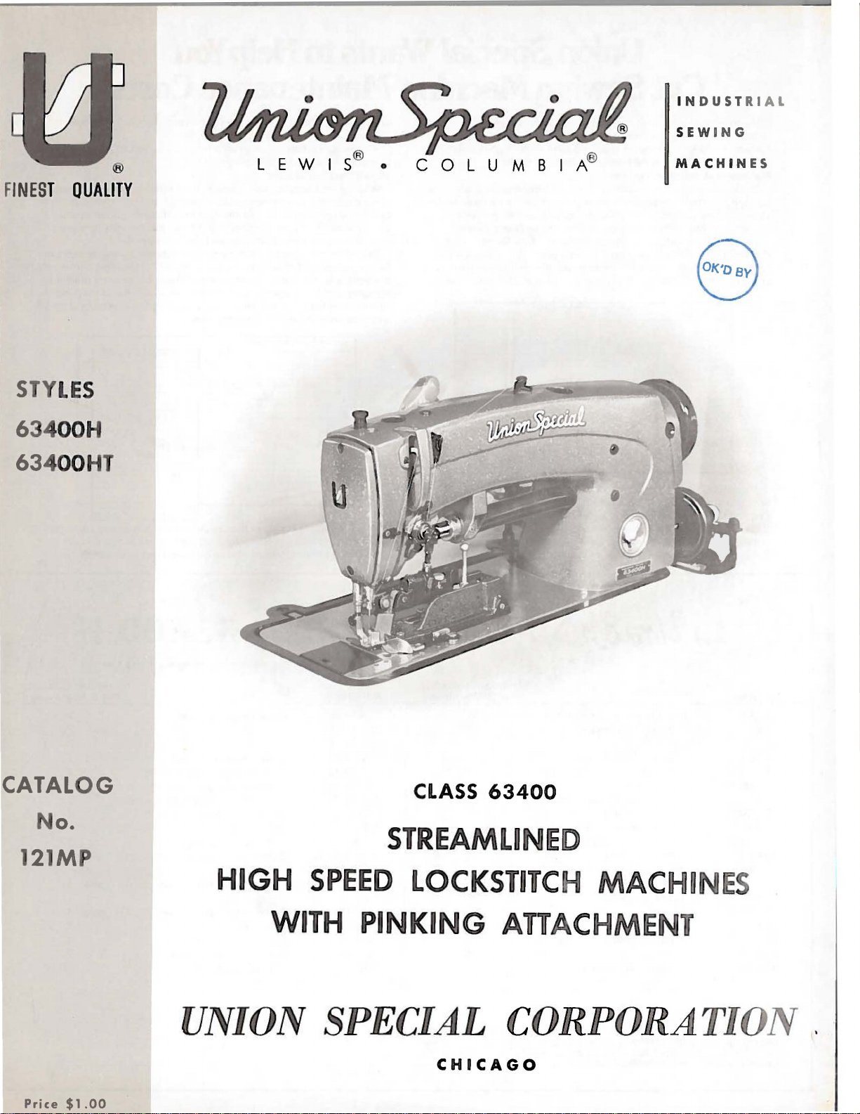
STY
LES
6 4
00H
634
00HT
C 0 L U M B I A®
MACHIN
8
ES
CATALOG
No.
121MP
HI
GH S
PEED
WITH
PINKING
CLASS
S
TREAMLI
63400
LOCKSTIT
AT
UNION SPECIAL CORPOR
CHICAGO
Price
$1.00
ED
C
AC
MA
C
HME
~
AT
S
Page 2
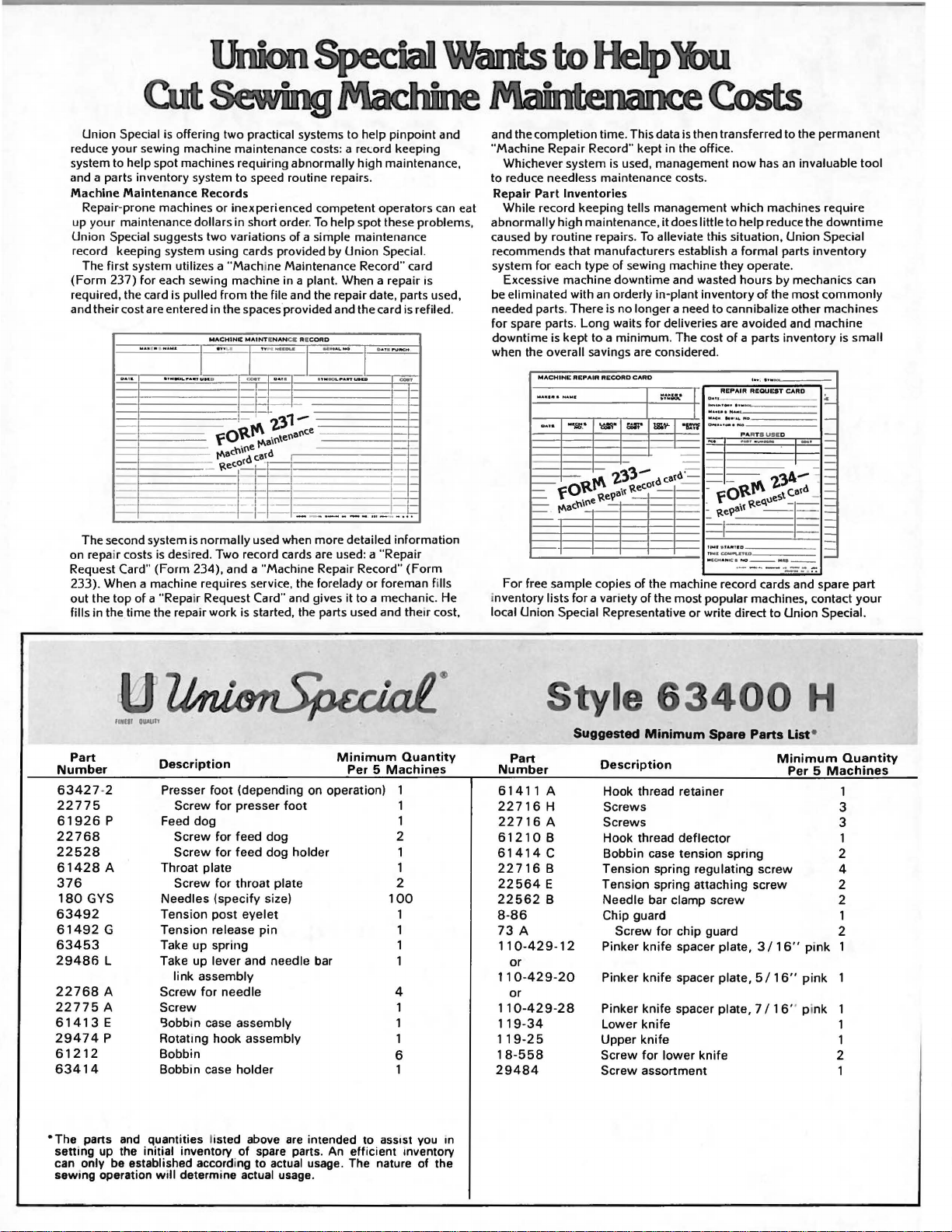
Union Special is offering two practical systems to help
reduce your sewing machine maintenance costs: a
system to
and a parts inventory system to speed routine repairs.
Machine
up your maintenance
Union Special suggests two variations
record keeping system using cards provided by Union
(Form
required, the card is pulled
and their cost are entered in the spaces'provided and the card is
on repair costs is desired. Two record cards are used: a "Repair
Request
233). When a machine requires service, the forelady
out
fills in the time the repair work is started, the parts used and
help spot machines requiring abnormally high maintenance,
Maintenance Records
Repair-prone machines
The first system utilizes a "Machine Maintenance Record" card
237) for each sewing machine in a plant. When a repair IS
........
........
IYM.OI..P'AitTUIIt
D4
"
The second system is
Card"
(Form
the top
of
a "Repair Request Card" and gives it to a mechanic. He
or
inexperienced competent operators
dollars in short order.
from
the file and the repair date, parts used,
MACHINC
MAINTI
.
..
u
'
I I I I
D
-
+
~:J ~
ottl'\
f . \enan
1'\8'"
1'\acnine catd
~tec.otd
.
1-
normally
234), and a "Machine Repair Record"
used when more detailed information
To
help spot these problems,
of
a simple maintenance
NAN
CC AICOAD
1 . ,
M•IAL NO
..
.,
L~oiiiiTUSCD
~~
D41
-
13
-:e
-
_
-
pinpoint
relord
keeping
Special.
D.&? I
PUKM
-
__
'"
_ _
__
)7
-1~
1-
(Form
or
foreman fills
the1r
and
can
refiled.
cost,
and the
completion time . This data is then transferred to the permanent
"Machine Repair Record" kept in the office .
Whichever system is used, management
to reduce needless maintenance costs.
Repair
Part
While
eat
abnormally high maintenance, it does little to help reduce the
caused by routine repairs.
recommends that manufacturers establi
system
Excessive machine downtime and wasted hours
eliminated with an orderly in-plant inventory
be
needed parts. There is no longer a need to cannibalize other machines
for spare parts. Long waits for
downtime
when the overall savings are considered .
Inventories
record keeping tells management which machines require
To
alleviate this situation , Union Special
for
each type
is
kept
MACHINE
"'""''"'
........
-··
=
fO~~el'ait
~
-
1'\ac."'"
f--
REPAIR
-a;
of
sewing machine they operate .
deliveries are avoided and machine
. The cost
CARD
:::~
!&
'I'-
~
~tec.otd
c,at
"L"l'f
d'
-
_•
to a
RECORD
'<::!"
minimum
2'3'3-
- -
For
free sample copies
inventory
local
lists
Union
for
Special Representative
a variety
of
the machine record cards and spare part
of
the most popular machines, contact
now
has
an
invaluable tool
sh
a formal parts inventory
by
mechanics can
of
the most
of
a parts inventory is
....
;
•..
REPAIR
RltQUUT
Daoo
I
,_,
......
...
..
...
...
I
'""""
.......
-···-·-
-
-
fO~f'\
- .
~t
~'t
t
...
l'
l f AfU I D
,
...
coo."'-&T&D
M
ICH•HOCihO--H·--
·--····----
or
write direct to Union Special.
CARD
-.
PA
RT S
USE
D
·-·
~teq\les
2'3A-
\
catd
I
-·
..
downtime
commonly
~
-
-
=
~
=
-
=
-
-
I=
I=
-
small
your
holder
intended to
Minimum
Per 5 Machines
Part
Number
63427
-2 Presser
22775
61926
22768
22528
61428
376
180
63492
61492
63453
29486
22768
22775
61413
29474
61212
63414
"The
sett
can only be established according to actual usage. The nature of the
sew
p
A Throat plate 1
GYS
G
L Take
A
A
E
p
parts and
ing up the initial inventory
ing operation
Description
foot
Screw
Feed
Screw
Screw
Screw
Needles
Tension
Tension
Take
link
Screw
Screw
'3obbin case assembly 1
Rotatmg hook assembly
Bobbin
Bobbin case
quant1t1es
will
determine actual usage.
(depending on operation) 1
for
presser
dog
for
feed
for
feed
for
throat
(specify
post
release
up
spring 1
up
lever
assembly
for
needle
holder
listed above
foot
dog
dog
plate
size)
eyelet
pin
and needle bar
of
are
spare parts. An efficient mventory
Quantity
1
1
2
1
2
100
1
1
1
4
1
6
1
ass1st
you
1n
Part
Number
61411A
22716
22716
61210
61414
22716
22564
22562
8-86
73
110-429-12
H
A
B
c
B
E
B
A
or
110-429-20
or
110-429-28
119-34
119-25
1
8-558
29484
tyle
Suggested
Minimum
Description
Hook thread retainer
Screws
Screws
Hook thread
Bobbin case
Tension
Tension
Needle
Chip guard
Pinker
Pinker
Pinker
Lower
Upper
Screw
Screw
spring attaching
bar clamp
Screw
knife
knife
knife
knife
knife
for
assortment
400
Spare
deflector
tension
spring regulating
for
chip guard
spacer plate, 3 I
spacer plate, 5 I
spacer
lower
spring
screw
plate,
knife
Parts
Ust
Minimum
Per 5 Machines
screw
screw
16"
16"
7 I 16" pi
•
pi
nk
pink
nk
Quantity
1
3
3
1
2
4
2
2
1
2
1
1
1
2
1
Page 3
Catalog
(Supplement
No.
to
Catalog
INSTRUCTIONS
FOR
121
MP
No.
121
M)
ADJUSTING
Streamlined
63400
Union
Rights
LIST
CLASS
H
First
Copyright
Special
Reserved
AND
OF
Styles
Edition
by
in
OPERATING
PARTS
63400
Lockstitch
63400
19
6 3
Corporation
All
Countries
HT
October~
1977
UNION SPECIAL
INDUSTRIAL
CHICAGO
Printed
CORPORATION
SEWING
in
3
MACHINES
U.S.
A.
Page 4
IDENTIFICATION
OF
MACHINES
Each
into
the
special.
contain
the letter
is s
uffixed
Styles
which
differs
This
junction
not
on Style
clarity,
63400
Hand
Opposite
number,
use
the
part
Adjusting
with
Styles
UNION
name
plate
Standard
the
letter
"Z".
of
When
to
the
machines
from
catalog
therewith.
s
63400
certain
HT
the
description,
number
and
63400
SPECIAL
on
Style
"Z''.
only
standard
machine
the
machine.
numbers
Example:
minor
Style
similar
the
style
number,
APPLICATION
is a supplement
Only
A
63400
those
or B are
A
or
parts.
illustration
and
amount
listed
operating
H
and
in
instructions
HT.
is
"Style
changes
number.
in
construction
to
parts
illustrated
B
parts
page,
required.
the
second
identified
Style
have
in
one
63400
that
Catalog
which
are
parts
column.
included
by a Style
numbers
or
H".
are
made
Example:
are
it
contains
OF
CATALOG
No.
are
used
and
listed
shown
are
identified
When
are
classified
more
letters
Special
in a standard
"Style
grouped
no
letters.
121
M
and
on
Styles
at
the
in
phantom
ordering
represent
number
which
suffixed,
Style
63400
numbers
HZ".
under a class
Example:
should
63400
back
of
to
by
detail
repair
only
areas
is
as
standard
machine,
be
used
Hand
this
book.
help
number,
parts
concerned
stamped
but
never
contain
number
"63400".
in
HT
locate
always
and
a 112
con-
and
For
the
part
11
The
herein.
in
this
given
of
High
and
Hook
from
handwheel
Speed
Heavy
Shaft,
Enclosed
Control,
Feed
Feed
63400
Eccentric,
Timing
H
similar
the
throw-out
63400
HT
ranging
catalog
It
can
class.
the
is
Streamlined
Duty,
Push
Automatic
Automatic
on
For
garments
width
Same
from
applies
also
specifically
be
applied
Reference
operator's
toward
the
LongArmLockstitch
with
Pinking
Button
Stitch
Lubricating
or
Manual
Needle
Lower
Bearings
Main
simultaneously
made
of
pink
for
ranging
pinking
as
Style
3/8
to
knife.
7/8
with
to
direction,
position
operator.
STYLES
Attachment,
Shaft.
seaming
of
light
from
63400
of
an
to
the
discretion
such
while
seated
OF
Regulator,
System.
Head
for
Oiling
Take-up
and
to
medium
3/16
H,
except
inch.
Standard
to
some
as
right,
at
the
MACHINES
Machines,
Drop
Stitch
Head
Length
Oil
Control,
Lever
pinking
weight
to
3/4
of
three
rows
Styles
Special
left,
machine.
One
Feed,
Siphon,
and
on
materials.
an
inch
of
of
front,
Needle,
Rotary
Indicator,
Needle
Needle
house
and
feed
machines
Styles
back,
Operating
Light,
Hook,
One
Adjustable
Bearing
Bar
Driving
dresses,
Two
rows
manually
and
the
width
as
of
machines
etc.,
direction
Medium
Horizontal
Reservoir
Hook
Adjustable
slips
of
operated
of
listed
are
Oil
Link,
and
feed,
pink
NOTE:
The
pinking
width
knife.
of
pink
is
measured
from
4
the
centerline
of
needle
to
the
point
of
Page 5
Each
type
number
The
size
blade
number
UNION
denotes
number,
measured
and
the
SPECIAL
the
stamped
in
thousandths
size
number
kind
needle
of
shank,
on
the
represent
has
needle
of
an
NEEDLES
both a type
point,
inch
shank,
the
length,
across
complete
number
groove,
denotes
the
symbol.
and a size
finish
the
largest
eye.
Collectively,
number.
and
other
diameter
The
details.
of
the
type
the
Needle
and
sizes
Type
180
GYS
To
needle,
A
complete
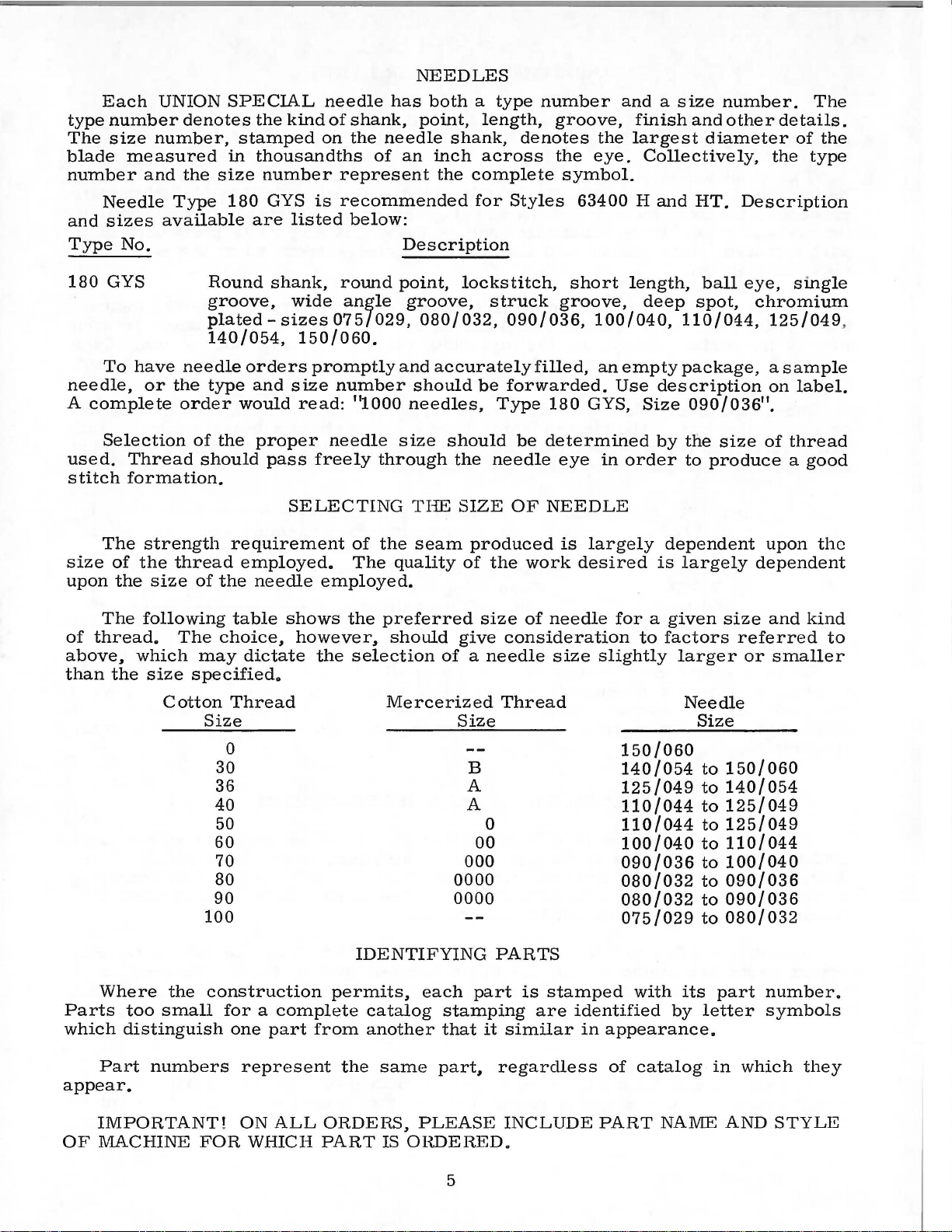
Selection
used.
stitch
The
size
upon
The
of
thread.
above,
than
the
available
No.
have
or
Thread
formation.
strength
of
the
the
size
following
which
size
Type
the
order
thread
The
180
GYS
is
recommended
are
listed
Round
groove,
plated140/054,
needle
type
of
the
should
of
the
choice1 however1 should
may
specifiedo
shank,
wide
sizes
150/060.
orders
and
would
proper
requirement
employed.
needle
table
dictate
promptly
size
read:
pass
freely
SELECTING
shows
the
round
angle
075/029,
number
needle
employed.
below:
Description
point,
groove,
and
"1000
size
through
of
the
The
quality
the
preferred
selection
lockstitch,
080/032,
accurately
should
needles,
should
the
THE
SIZE
seam
of
give
of a needle
for
Styles
struck
090/036,
filled,
be
forwarded.
Type
be
needle
OF
produced
the
work
size
of
consideration
63400
short
groove,
100/040,
an
empty
Use
180
GYS,
determined
eye
in
order
NEEDLE
is
largely
desired
needle
size
for a given
slightly
Hand
length,
deep
110/044,
package,
description
Size
by
dependent
is
largely
to
factors
larger
HT.
Description
ball
eye,
spot,
090/036".
the
size
to
produce a good
size
referred
or
single
chromium
125/049
as
ample
on
of
thread
upon
dependent
and
smaller
,
label.
the
kind
to
Where
Parts
which
appear.
OF
too
distinguish
Part
IMPORTANT
MACHINE
Cotton
Size
100
the
construction
small
numbers
FOR
Thread
0
30
36
40
50
60
70
80
90
for a complete
one
part
from
represent
!
ON
ALL
WHICH
PART
Mercerized
IDENTIFYING
permits,
catalog
another
the
same
ORDERS,
IS
Thread
Size
B
A
A
0
00
000
0000
0000
PARTS
each
PLEASE
ORDERED.
part
stamping
that
it
similar
part1 regardless
INCLUDE
is
stamped
are
150/060
140/054
125/049
110/044
110/044
100/040
090/036
080/032
080/032
075/029
with
identified
in
appearance.
of
catalog
PART
Needle
Size
to
to
to
to
to
to
to
to
to
its
by
letter
NAME
150/060
140/054
125/049
125/049
110/044
100/040
090/036
090/036
080/032
part
in
which
AND
number.
symbols
they
STYLE
5
Page 6

The
arrangement
replacement
parts
for
ORDERING
of
this
Styles
OF
catalog
is
to
63400 H and
REPAIR
facilitate
63400
HT.
PARTS
easy
and
accurate
ordering
of
Two
listed
presents
On
the
part
view
Numbers
the
position
in
ordering
exploded
Sub-assemblies~
or a solid
can
description
1
2
3
4
5
6
7
exploded
in
this
catalog
a
sector
page
numbers~
being
opposite
shown.
in
of
parts.
view
line
be
furnished
of
29482
447-137
22729 c
1012
71-29
869 L
4124-33
descriptions
the
the
plate
box
for
the
B
L
view
of
part
plates
and
Style
the
machine~
the
illustration
first
column
in
the
Always
carries
which
on
the
picture
repairs~
main
sub-assembly.
Pinking
cover
63400 A covered
parts
will
and
the
number
are
reference
illustration.
use
the
part
a
reference
are
sold
complete~
plate.
are
indicated
Attachment~
Ball
Joint
Screw-----------------------------------
Nut#
Connecting
Nut~
Ball
Joint#
the
differences
being
aligned
be
found a listing
Reference
number
number
Component
by
Example:
Connecting
right
hand
Rod---------------------------
left
hand
lower-------------------------
in
Catalog
as
of
pieces
numbers
numbers
listed
for
or
by
separate
parts
indenting
between
in
required
only#
in
the
each
of
their
the
No.
121
their
assembled
of
the
in
and
should
second
part
available
part1 are
sub-assemblies~
descriptions
complete--------------------
Rod
thread
Assembly
--------------------
-----------
thread----------------------
Standard
M.
Each
parts
the
with
particular
merely
never
column.
in a bracket
Styles
plate
position.
their
indicate
be
used
Each
for
sale.
which
under
the
1
1
1
1
1
2
1
In
those
catalog#
the
parts
mentioned
illustration.
Success
UNION
oration,
to
the
SPECIAL
its
most
Maximum
Genuine
repair
parts
trademark
Prices
are
forwarded
otherwise
cases
no
specific
for
the
in
the
in
subsidiaries
approved
efficiency
needles
are
is
your
are
strictly
f.
directed.
where a part
usage
various
description#
USE
GENUINE
the
operation
Needles
and
scientific
and
durability
are
stamped
guarantee
net
o.
b.
shipping
A
is
will
machines
and~
NEEDLES
of
and
Repair
authorized
principles,
packaged
with
the
of
cash
and
point.
charge
common
be
mentioned
are
not
if
necessary~
these
machines
Parts
distributors.
and
are
assured.
with
labels
Union
the
highest
TERMS
subject
Parcel
is
made
to
all
in
the
AND
as
REPAIR
furnished
are
marked
Special
quality
to
change
Post
to
cover
of
the
machines
the
description.
same#
the
the
difference
PARTS
can
be
secured
by
the
They
made
trademark~
in
materials
are
with
~
without
shipments
the
postage
specific
will
only
Union
designed
the
utmost
U S
and
notice.
are
covered
by
However#
usage
be
shown
with
Special
will
in
genuine
Corp-
according
precision.
®
•
Genuine
Emblem.
workmanship.
All
shipments
insured
and
unless
insurance.
this
when
be
the
Each
6
Page 7

INSTALLING
CAUTION!
on
hand
wheel.
Before
carefully
packing
leaving
packed.
box~
the
PREPARATION
A
bag
of
assembly
attaching
screw~
miscellaneous
Insert
the
upper
STANDARD
Included
ing
one
its
clamp
and
screw~
washers
up
the
hinge
frame
ACCESSORIES
also
bobbin
spring~
four
and
nuts~
machine.
When
Using
unpacking~
both
factory~
After
following
OF
MACHINE
parts~
one
extra
attachments
studs
eyelet
with
winder
one
in
(A~
each
assembly~
knee
isolator
and
one
hands
each
the
machine
steps
FOR
consisting
bobbin~
to
the
holes
provided
Fig.
machine
lifter
pade
machine
DO
NOT
on
bed
Union
should
lift
casting~
Special
and
accessories
be
followed:
INSTALLATION
of
two
hinge
bed
plate~
for
2).
is a box
the
machine
assembly
and
rest
and
clips~
pin.
machine
lift
machine
one
frame
studs~
is
packed
them
of
in
STANDARD
mounting
its
rubber
one
chip
These
parts
out
of
box
gently.
is
sewed
have
been
thread
and
two
with
each
rear
of
ACCESSORIES-
frame~
pad~
chute~
are
by
off~
removed
eyelet~
screws
machine.
cloth
plate.
one
bed
positioning
its
attaching
essential
placing
inspected
for
oil
drain
when
one
hand
and
from
one
the
eyelet
holding
Assemble
contain-
jar
and
spring
screws~
setting
TABLE
Lockstitch
the
bed
TABLE
BOAR
D
TOPS
plate
machines
is
FLUSH
are
with
installed
the
top
of
in
the
table
tops~
machine
prepared
mounting
with
frame.
cut-out~
so
that
66 0 -168
7
Fig.
1
Page 8

INSTALLING
(Continued)
MACIITNE
MOUNTING
On a suitable
c
ut-out
t
hrough
o
ver
t
he
n
uts
1/ 16
r
etaining
s
ide
m
achine
f
all
play
with
left
right
retaining
lightly.
Place
sewing
inch
plate
of
the
Tip
the
mounting
away
from
of the
the
hinge
hinge
plate
clearance
board
machine
cross
Before the
lifter
maximum
within the
bar
rod
should
lift
head.
raises approximately
tableboard,
hinge
pad
pad;
( 213 9 3 R)
head
smartly
and
back
frame
the
operator.
shaft
machine
be
adjusted.
of
the
This
FRAME
lugs
to
and
tighten
insert
in
the
between
upward
tighten
against
with
should
is
put
presser
may
5/16
INSTALLATION
place
the
machine
rear
(Fig.
securely.
round
to
head
outside
frame
the
mounting,
cloth
with a hammer
locking
the
nuts
the
rest
attaching
Assemble
be
taken
into
production,
The
left
stop
bar
and
its
be
clone
by
inch.
mounting
Assemble
wood
front
plate
securely.
pin,
holes
the
knee
up
by
screw
parts
setting
1).
screw
of
pan
and
edge
to
and
the
the
do
the
frame
Insert
bed
and
the
positioning
tighten
section,
after
and
being
the
insure a good
assemble
to
the
right,
press
cone
(22597
bell
not
stop
assembly
bearings,
crank
F)
interfere
screw
(21393
U)
countersunk
spring ( 63474
securely.
as
shown,
sure
frame
sides,
grip
chip
chute
so
that
as
shown.
but
(21665
should
be
with
so
that
in
the
wood
and
there
on
(51278
the
must
J)
of
set
so
moving
the
machine
screw
Assemble
snug
is
about
rap
the
under-
F)
chips
will
All
not
bind.
the
knee
that
parts
presser
A)
up
the
to
end
the
BOBBIN
WINDER
The bobbin
located directly
when
allow
The
against
is
Catalog
in operation.
the
mechanism
pulley
the
described
No.
of
belt
under
121
BELTS
These
Thread
enlarged
machines
machine
for
clarity.
CAUTION!
the
reservoir
winder
in
the
to
M.
Oil
must
should
front
The
to
winder,
wind
"Winding
are
as
indicated
Needle
has
be
filled
be
of
the
base
be
of
moved
when
the
bobbin.
the
equipped
is
been
drained
before
secured
sewing
the
winder
closer
in
operation,
Regulation
Bobbin",
to
use
THREADING
in
Fig.
threaded
OILING
from
starting
to
the
machine
has
to
or
under
either
2.
Threading
from
the
to
table
belt
and
two
elongated
farther
should
and
operation
OPERATOR'S
# 1
"Vee"
left
to
right.
main
reservoir
operate.
top
will
away
exert
or
at
so
that
bear
attaching
from
only
of
round
check
before
its
puller
against
belt
enough
the
bobbin
holes.
will
the
as
needed.
pressure
winder
which
INSTRUCTIONS
belts.
spring
has
been
shipment
be
belt
in
and
Fill
oil
is
be
added
straight
in
the
main
at
maximum
when
mineral
main
reservoir
level
needle
oil
reservoir.
at
plug
is
when
in
needle
yellow
of a Saybolt
This
is
screw
(B,
is
band
marked
viscosity
equivalent
in
Fig.
yellow
11
of
90
to
2)
and
band
LOW".
to
Union
125
8
check
marked
oil
"FULL".
Use a stainless
seconds
Special
at
specification
level
100°
at
gauge
Oil
(C);
should
water-white
Fahrenheit
No.
17
5.
Page 9

OILING
(Continued)
It
is
a
long
After
period,
oiling,
machine
speed
operation
The
The
oil
control
manual
and
five
oiling
turn
or
preferably
Oil
may
The
quantity
dial
in
the
clockwise
NOTE:
lever
shaft
bearings
recommended
be
lubricated
replace
slowly
for
can
machine
is
stud
of
the
stud
180°
six
drops
at
starting
be
of
drained
of
direction
direction
All
moving
front
and
knife
and
holder
that a new
head
several
then
be
provided
(D,
Fig.
head
to
mechanism
expose
oil
should
time
from
oil
supplied
of
the
arrow
decreases
parts
rear,
shaft.
by
removing
cover
minutes
expected
with
2)
is
the
manual
be
and
mid-day.
main
to
the
of
pinking
also
oil
Major
Fig.
machine,
as
no
to
without
automatic
shown
be
introduced
reservoir
the
2
or
the
head
further
distribute
damage.
or
in
the
desired,
oiling
hook
is
one
cover
hand
manual
automatic
remove
port.
into
by
removing
controlled
(counterclockwise)
flow
of
oil.
attachment
two
oil
holes
oiling
9
for
points
that
has
and
oiling
oil
to
head
oiling
In
the
the
oiling
increases
to
be
oiled
lubricating
are
marked
been
oiling
will
the
various
mechanism
position,
locking
manual
port
plug
screw
by
dial
the
once
both
in
out
the
be
required.
screw
oiling
(E).
oil
daily.
red
of
service
moving
parts.
oil
control.
and
(G,
position,
twice
(F,
daily
Fig.
Turning
flow
and
Oil
sides
on
of
attachment.
for
parts.
Run
Full
should
Fig.
2)
2).
the
in
knife
lever
-
a
Page 10

INSTRUCTIONS
FOR A TTACIDNG
AND
ADJUSTING
PINKING
ATTACHMENT
29"
132
Fig.
2A
NOTE:
Styles
6_;3400
addition
All
63400 H and
Ii
covered
a 1
attachment.
ATTACIDNG
Check
lower
ing
rod
(Fig.
and
turn
to
obtain
Insert
in
end
(G)
against
Place
joint
tighten
Insert
washer
screw
(B)
the
ball
joints
assembly.
2A).
the
1
29/32
the
of
pinker
washer
and
screw
the
(M)
into
the
instructions
HT
in
instructions
PINKING
center
(A~
The
To
make
connecting
inch
upper
ball
driving
the
flat
on
(H)
then
screw
(K).
large
in
base
base
of
pertaining
are
the
Catalog
No.
pertain
ATTACHMENT
distance
B~
Fig.
2A)
distance
any
adjustment,
rod
(E)
in
dimension.
joint
(A)
shaft
ball
over
(F)
stud.
ball
into
hexagonal
of
pinking
machine.
to
the
same
121
as
M.
only
between
of
the
should
loosen
the
direction
Tighten
into
the
and
tighten
stud
of
the
pinker
head
screw
attachment
adjustment
those
The
to
the
the
upper
pinker
be
1
29/32
nuts
nuts
eccentric
set
the
lower
arm
(L)
and
of
for
Style
following
pinking
and
connect-
inch
(C,
D)
required
securely.
hole
screw
ball
(J)
and
and
its
tighten
SETTING
To
attachment
of
pink
NOTE:
point
may
bind
graph
SETTING
Set
Fig.
below
pinker
of
travel.
THE
set
and
of
pinking
and
"Setting
THE
the
2B)
so
top
edge
arm
the
to
The
upper
(B)
make a pencil
1/32
(Fig.
turn
tion
lowest
the
knife
of
inch
2B),
handwheel
until
point
1/32
so
it
lower
from
the
inch
coincides
knife.
WIDTH
width
the
left
to
the
width
knife.
it
may
Pinker
UPPER
pinking
its
point
of
lower
is
at
For
this
line
lower
loosen
inoperating
pinker
of
travel.
pencil
Tighten
OF
PINK
of
pink~
or
right
right
of
In
be
necessary
Driving
loosen
as
increases
pink
is
setting
Shaft".
KNIFE
knife
is
1/32
knife
its
lowest
adjustment~
on
upper
front
screw
(A~
inch
when
point
knife~
point
(C)
and
direc-
arm
line
with
is
at
Now~
on
upper
top
screw
its
set
edge
(C).
screw
required.
the
measured
pinking
to
move
(L~
Fig.
Moving
width
from
of
the
attachment
the
pinker
2A)
base
pink.
center
for a wide
driving
and
to
the
Tighten
line
move
left
of
pink
shaft:
base
decreases
screw
the
needle
the
refer
of
pinking
width
securely.
to
the
ball
joint
to
para-
NOTE:
both
Knife
ends.
can
be
sharpened
on
10
Fig.
2 B
Page 11

TIMING
upper
top
advance
The
knife
edge
THE
pinker
of
the
repositioning
Access
Fig.
loosen
wrench
moving.
feed
2C).
the
in
dog,
to
Using a 1/8
two
the
Turn
or
relationship
screws
securely
FINKE
is
timed
(in
its
lower
material.
the
pinker
this
gear
screws
last
the
backward
mentioned
and
R
correctly
upward
knife
This
driving
is
obtained
inch
in
the
screw
loosened
handwheel
to
above
replace
travel)
when
the
timing
gear
hexagonal
hub
of
forward
retard
the
is
attained.
plug.
when
is
1/16
feed
can
on
by
removing
socket
driving
to
prevent
feed
the
inch
dog
be
the
gear,
to
advance
dog,
Tighten
point
of
above
begins
changed
main
shaft.
plug
key
wrench
leaving
gear
until
the
the
to
by
(A,
from
the
the
both
SETTING
Moving
margin
bind.
To
should
(B,
Fig.
shaft
and
There
timing
as
tighten
should
has
PINKER
the
may
eliminate
be
relocated.
2C)
required
screws.
not
pinking
cause
and
be
no
been
DRIVING
attachment
the
ball
this
Loosen
loosen
and
while
Push
end
play
changed.
SHAFT
joints
bind
screws
holding
thrust
in
the
(A,
the
pinker
screws
in
shaft
collar
pinker
to a wide
B,
Fig.
driving
in
thrust
the
hub
in
position
(N,
Fig.
driving
of
pinking
2A)
to
shaft
collar
driven
move
2A)
against
shaft.
(N,
gear.
gear
Check
Fig.
Move
lug
to
Fig.
2A),
pinker
against
and
tighten
be
sure
2 C
remove
bed
screws.
the
plug
driving
casting
pinker
11
Page 12

12
Page 13

PINKER
THROAT
DRIVE
MECHANISM,
PLATES
AND
PRESSER
FEED
FEET,
DOGS
Ref.
No.
1
2
3
4
5
6
7
8
9
10
11
12
13
14
14A
15
16
17
18
19
20
21
22
23
24
25
26
27
28
29
30
31
32
33
34
35
36
37
37A
37B
38
39
40
41
42
43
44
45
46
47
48
Part
No.
61926
61428 B
63427-3
63430
63430
61330
63430
63430-3
22798
61926
61428
110-429-12
110-429-20
110-429-28
63427-2
63430
63430
61330
63430
63430-2
22798
63494
63479 F
22894
22525
63493
63479
22651
29475
22894
22839
22894
63479
63479 A
63479
63979
22730
63479
22657
21705
22894
21393
SC182
51278
N
A
E
B-39
B
8-66
p
A
73 A
8-86
A
E
B-35
B
8-66
B
J
c
A
E
CD-3
BK
v
u
G
c
A
666-244
D
E-24
666-198
c
93
u
F
652
B-12
651 H
Description
Feed
Throat
Presser
Feed
Throat
Pink·~r
Pinker
Pinker
Presser
Plug,
Pinker
Bed
Pinker
Main
Pinker
Pinker
Bushing,
Oil
Screw---------------------------------------------Bushing,
Screw---------------------------------------------Felt
Thrust
Screw,
Oil
Screw----------------------------------------------
Chip
Lock
Nut
Dog,
Presser
Spring
Hinge
Yielding
Presser
Screw------------------------------------------
Presser
Dog,
Screw------------------------------------------
Chip
Presser
Spring
Hinge
Yielding
Presser
Screw------------------------------------------
Presser
Screw-----------------------------------------Screw------------------------------------------
Plug
Screw------------------------------------------
Shaft
Screw-----------------------------------------Screw-----------------------------------------Screw------------------------------------------
Shield,
Felt
Oil
Screw------------------------------------------
Drip
Disposal
Washer----------------------------------------
------------------------------------------------
22
teeth
Plate,
Foot,
Plate,
Knife
Knife
Knife
Foot,
for
Shaft
Shaft
Driving
Driving
Liner--------------------------------------
left
Wick,
Collar---------------------------------------
for
Pan----------------------------------------
for
Foot
-----------------------------------------
Pin
Section--------------------------------Foot
Foot
22
teeth
for
Guard
Spacer
Spacer
Spacer
Foot
-----------------------------------------
Pin
Section--------------------------------Foot
FootGuard
pinker
Driven
------------------------------------------Driving
Assembly---------------------------------
right
for
---------------------------------------
61414
Chute
per
inch,
Style
for
Shank
-------------------------------------Bottom,
Guard
Style
-------------------------------------
for
Shank
-------------------------------------Bottom,
driving
Shaft---------------------------------
Shaft
--------------------------------------
pinker
for
pinker
A----------------------------------
63400
Style
Style
63400
per
inch,
63400 H -----------------------
Plate,
Plate,
Plate,
63400 H ----------------------
Gear
Gear----------------------------
Sleeve---------------------------
driving
---------------------------------
for
Style
HT
---------------------
HT
---------------------
-----------------------------
marked
----------------------------for
3/16
5/16
7/16
-----------------------------
marked
-----------------------------
gear
access
----------------------------
shaft
driving
''AE-3
Style
inch
inch
inch
"AE-2"
hole--------------
bracket
shaft-----------------
13
63400
63400 H ---------
pink
pink
pink
HT
11
-------------
-------------
-------------
-------------
-------------
------------
--------
Amt.
Req.
1
1
1
1
1
1
1
1
2
1
1
1
2
1
1
1
1
1
1
1
1
1
1
2
1
2
1
2
3
1
1
2
1
2
2
1
1
1
1
1
1
1
1
2
1
1
2
1
1
2
1
2
2
Page 14

24
14
Page 15

PINKING ATTACHMENT
Ref.
No.
1
Part
No.
29482 B
2 447-137
3
4
22729
1012 L
5 71-29
6
869 L
7 4124-33
8
9
10
11
12
13
14
15
16
17
18
19
20
21
22
23
24
25
26
27
28
29
30
31
32
33
34
35
36
37
38
39
40
41
42
43
44
45
40-57
39536
1160
18-844
45-248
46-108
1776 L
18-71
CS331
CS231
40-101
45-249
34-26
18-558
119-25
3-46
119-34
475-68
99-143
21210 A
810 L
99-329
40-86
18-353
18-422
14-171
76-18
1203 L
45-247
14-172
99-134
18-178
21-309
18-547
1012 L
18-501
40-46
18-544
c
AD
L
Description
Pinking
Attachment,
Ball
Joint
complete
Connecting
--------------------
Rod
Assembly----------Screw---------------------------------Nut,
Connecting
Nut,
Ball
right
left
hand
Joint,
hand
thread
-------------------
Rod--------------------------
thread---------------------
lower-----------------------VVasher------------------------------------VVasher-------------------------------------
N~
----------------------------------------
Screw--------------------------------------
Lever,
Link,
for
for
throw-out
knife
throw-out---------------------
------------------------
Screw-------------------------------------Screw-------------------------------------Screw,
Nut,
for
for
No. 34-26
4124-33
--------------------------
-------------------------VVasher------------------------------------Lever,
Cam
Screw,
for
knife
Throw-out,
for
lower
throw-out
for
upper
cam--------------knife
knife----------------------UpperKnife--------------------------------Base--------------------------------------Lower
Edge
Edge
Knife
Guide
Guide
--------------------------------
---------------------------------
Holder--------------------------VVasher------------------------------------Screw--------------------------------------
Holder
-------------------------------------
VVasher------------------------------------Screw-------------------------------------Screw-------------------------------------Shaft,
for
base------------------------------
PinkerHandle-------------------------------
Screw,
for
No. 14-171
----------------------
PinkerArm---------------------------------
Shaft,
Holder,
Screw,
Flat
for
lever
for
for
-----------------------------
upper
No. 14-172
knife
----------------------
-----------------------
Spring---------------------------------
Screw------.--------------------------------
N~
----------------------------------------
Attaching
Screw,
for
No. 29482 B
VVasher-------------------------------------
Screw,
for
upper
knife-----------------------
--------------
-------------
Amt.
Req.
1
1
2
1
1
1
1
1
1
1
1
1
1
2
1
1
1
1
1
1
2
1
1
1
1
1
1
1
1
1
1
1
1
1
1
1
1
1
1
2
1
1
1
1
1
15
Page 16

WORLD'S
FINEST
QUALITY
*
INDUSTRIAL
SEWING
MACHINES
UNION
SPECIAL
maintains sales
facilities throughout the world. These offices
aid
you
in
the selection of the right sewing
equipment for your
Special representatives
tory trained
promptly
tion, there
and
and
is
a Union Special Representative
serve you. Check with
ATLANTA, GA.
BOSTON, MASS.
CHICAGO,
DALLAS,
LOS ANGELES, CAL.
NEW YORK, N.
PHILADELPHIA, PA.
ILL.
TEXAS
Y.
particular operation. Union
and
service men
are
able
to serve your needs
efficiently. Whatever your loca-
him
today.
MONTREAL,
TORONTO, CANADA
BRUSSELS,
LEICESTER,
LONDON, ENGLAND
PARIS, FRANCE
STUnGART,
and
service
are
CANADA
BELGIUM
ENGLAND
GERMANY
will
fac-
to
Representatives
industrial
UNION SPECIAL
400
N.
FRANKLIN
ancl cllstrlbutora In
cities
throughout
CORPORATION
ST.,
CHICAGO,
all
the
Important
world.
ILL.
60610
 Loading...