

Page 1
®
INDUSTRIAL
SEWING
F
INEST
STYLES
63
4000
63
400KD
QUALITY
LEWIS
•
COLUMBIA
MACHINES
CATALOG
No.
121KD
Second
Edition
CLASS
STREAMLINED
HIGH
THROW-OUT
SPEED
LOCKSTITCH
TRIMMING
63400
WITH
UNl'a
"
SEWING
~24
~
JM
'Aa1etea,
E.
,.~
SUPPLY
8th St.
..
CA
MACHINES
MECHANISM
CO.
90021
CORPORATION
CHICAGO
Page 2
Catalog
(Supplement
AD
JUST
No.
to
Catalog
INSTRUCTIONS
FOR
ING
AND
121
OPERATING
KD
No.
121
M)
Union
Rights
LIST
CLASS
Streamlined
63400
Reserved
D
Second
Copyright
Special
OF
Styles
Edition
by
in
PARTS
6
34
0 0
Lockstitch
63400
1970
Corporation
All
Countries
KD
CORPORATION
INDUSTRIAL
Printed
SEWING
CHICAGO
in
U.S.A.
2
MACHINES
May,,
1975
Page 3
IDENTIFICATION
OF
MACHINES
Each
into
the
special.
the
letter
11 Z11
•
When
to
the
Standard
Styles
which
"Class
This
junction
not
on
certain
parts.
Opposite
number,
NOTE:
Adjusting
those
in
catalog
ions
that
Union
name
Standard
11
11
Z
only
of
differs
63400".
catalog
therewith.
Style
63
63400 B
description
When
column.
Catalog
are
the
pertain
Special
plate
•
on
the
Style
numbers
Example:
minor
Style
number.
changes
machines
from
the
is a supplement
Only
400 B
the
are
parts
are
illustration
and
ordering
and
repair
operating
No. 121 M
ones
that
specifically
machine
is
machine.
have
"Style
63400 D
are
Example:
similar
style
in
number,
APPLICATION
to
those
parts
illustrated
shown
pages,
amount
required.
parts
instructions
for
Style
are
different
to
Styles
identified
Style
one
made
numbers
or
more
11
•
Special
in a standard
"Style
construction
in
that
OF
Catalog
which
and
listed
in
phantom
parts
always
No. 121 M
are
are
use
for
63400
from
B.
Style
63400 D
by a style
are
letters
Style
63400
are
it
DZ".
grouped
contains
CATALOG
used
at
to
the
help
on
back
identified
the
part
Styles
The
63400 D
only
63400 B,
or
KD.
number
classified
suffixed,
numbers
machine,
under a class
no
and
should
Styles
of
locate
number
63400 D
this
the
by
detail
and
book.
listed
KD
instructions
or
are
additional
which
as
standard
but
never
contain
a
"Z"
letters.
be
used
63400 D
number,
in
are
included
is
stamped
the
is
suffixed
number
Example:
and
KD,
For
clarity,
and
the
similar
instruct-
and
contain
letter
in
con-
but
KD
part
second
to
in
this
The
herein.
this
from
wheel
High
It
class.
the
is
toward
Speed
operator's
Trimming
Rotary
Hook,
Indicator,
Adjustable
Feed
Timing
Eccentric,
on
Inches.
63400 D
materials.
in
1/16,
Specify
recommended
63400 KD
trimmer)
catalog
can
also
Reference
the
Streamlined
Mechanism,
Horizontal
One
Reservoir
Hook
Needle
Lower
For
simultaneously
1
1/8,
width
Same
as
and
applies
be
applied
to
position
operator.
Oil
Control,
Main
13/64
3/16
of
speed
Style
Thread
specifically
direction,
while
Long
One
Needle,
Hook
Enclosed
Bearings
Shaft,
inch
and
trim
needle
1/4
margin
5500
63400 D,
Wiper,
with
discretion
such
seated
STYLE
Arm
Lockstitch
Light,
Shaft,
Automatic
Automatic
for
Maximum
seaming
bar
inch
R.
width
P.M.
except
prepared
to
the
as
right,
at
the
OF
MACHINES
Push
Button
Head
Take-up
Work
and
trimming
travel.
of
desired.
equipped
for
Standard
to
some
left,
machine.
Machines,
Medium
Stitch
Lubricating
Oiling,
Lever
Space
and
to
Type
trim
from
Seam
with
use
with
Styles
Special
front,
Operating
with
and
Heavy
Regulator,
System,
Needle
Needle
Right
on
light
180
the
Spec.
"Klipp-It
Needle
of
machine
Styles
back,
direction
Vertical
Duty,
Head
Bearing
Bar
of
Needle
to
medium
GYS
needle.
center
line
301-SSa-1.
11
Positioner.
as
of
machines
etc. , are
of
Throw-out
Drop
Stitch
Oil
Siphon,
Adjustable
Driving
Bar
Available
of
needle.
Maximum
(thread
listed
in
given
hand-
Feed,
Length
Link,
11
1/8
weight
under-
NEEDLES
I
Each
denotes
number,
Union
the
kind
stamped
Special
of
shank,
on
the
needle
point,
needle
has
both a type
length,
shank,
groove,
denotes
3
and a size
finish
largest
number.
and
other
diameter
The
details.
of
the
type
The
blade,
number
size
mea-
Page 4
NEEDLES
(Continued)
sured
the
size
needles
Needle
and
sizes
Type
180
To
sample
on
label.
Selection
used.
stitch
The
size
upon
of
above,
than
of
the
The
thread.
the
in
thousandths
number
packaged
Type
available
No.
GYS
have
needle,
Thread
formation.
the
which
size
needle
A
complete
of
should
strength
thread
size
of
following
The
may
specified.
of
represent
and
sold
180
GYS
are
Round
single
chromium
060.
orders
or
the
type
order
the
proper
pass
SELECTING
requirement
employed.
the
needle
table
choice,
dictate
an
inch
the
by
Union
is
recommended
listed
shows
however,
below.
shank,
groove,
promptly
and
would
needle
freely
The
employed.
the
the
selection
across
complete
plated -sizes
size
through
THE
of
the
preferred
should
the
Special.
round
wide
and
number
read:
size
SIZE
seam
quality
of a needle
eye.
symbol,
for
point,
angle
accurately
"1000
should
the
of
give
Collectively,
which
Styles
Description
028,
should
needle
OF
produced
the
size
consideration
63400 D and
lockstitch,
groove,
032,
be
Needles,
be
determined
THE
work
ofneedle
size
is
given
struck
036,
filled,
forwarded.
Type
eye
in
order
NEEDLE
is
largely
desired
for a given
slightly
the
short
040,
an
180
by
is
to
factors
KD.
type
on
length,
groove,
empty
the
to
dependent
largely
larger
number
the
label
The
description
deep
044, 048,
package,
Use
description
GYS,
size
size
produce a good
dependent
size
referred
or
ball
040"
of
thread
upon
and
smaller
and
of
all
eye
spot,
054,
the
kind
to
,
a
Cotton
Where
Parts
which
Part
appear.
Thread
Size Size Size
0
30 B
36
40
50
60
70
80
90
100
the
construction
too
small
distinguish
numbers
for a complete
one
part
from
represent
Mercerized
000
0000
0000
IDENTIFYING
permits,
catalog
another
the
same
each
part,
Thread
A
A
0
00
PARTS
part
stamping
that
is
regardless
is
stamped
are
similar
with
identified
in
appearance.
of
the
catalog
Needle
060
054
to
048
to
044
to
044
to
040
to
036
to
032
to
032
to
028
to
its
part
by
letter
060
054
048
048
044
040
036
036
032
in
number.
symbols
which
they
IMPORTANT!
OF
MACHINE
FOR
ONALL
WHICH
ORDERS,
PART
IS
PLEASE
ORDERED.
4
INCLUDEPART
NAMEAND
STYLE
Page 5
The
arrangement
replacement
parts
for
ORDERING
of
this
Styles
catalog
63400 D
OF
is
and
to
REPAIR
facilitate
KD.
PARTS
easy
and
accurate
ordering
of
Four
listed
presents a sector
On
the
part
view
the
in
exploded
or a solid
can
description
18
19
20
are
commended,
numbers,
being
Numbers
position
ordering
Sub-assemblies.
be
It
not
exploded
in
this
page
shown.
of
parts.
view
line
furnished
of
29126
63487
22894
will
DZ
c
J
be
listed.
catalog
opposite
in
the
plate
box
the
noted
The
so
view
ofthe
descriptions
the
first
part
Always
on
for
main
in
reason
the
complete
plates
and
machine,
the
illustration
in
carries
which
the
picture
repairs.
sub-
Knife
Knife
Set
the
cover
Style
column
the
use
Drive
above
is
63400 B covered
parts
and
the
are
illustration.
the
a
reference
are
sold
plate.
are
indicated
assembly.
Eccentric
Drive
Screw
example
that
sub-assembly
the
differences
in
being
will
number
reference
part
complete.
Component
Example:
Eccentric
-----------------------------------------
replacement
aligned
be
found a listing
of
numbers
Reference
number
number
or
by
indenting
Assembly
Connecting
that
the
of
should
pieces
listed
by
these
between
Catalog
as
in
required
numbers
in
for
each
separate
parts
their
•.
144
eccentric
parts
be
ordered.
No.
their
of
only,
the
part
of
sub-
descriptions
inch
Rod----------
and
individually
the
Standard
121 M.
assembled
the
parts
in
and
merely
should
second
available
part,
are
assemblies.
throw---------
the
needle
Each
position.
with
the
particular
indicate
never
column.
be
for
in a bracket
under
----
bearing
is
not
Styles
plate
their
used
Each
sale
which
the
--
re-
.
1
1
2
Success
Union
ation.
to
Maximum
repair
your
are
otherwise
hand
carefully
packing
Special
its
the
most
Genuine
parts
guarantee
Prices
forwarded
CAUTION!
on
Before
in
the
Needles
subsidiaries
approved
efficiency
needles
are
of
are
strictly
f.
directed.
When
handwheel.
leaving
packed.
box,
the
following
USE
GENUINE
operation
and
scientific
and
are
stamped
the
highest
o.
b.
shipping
A
charge
unpacking.
Using
factory.
After
Repair
and
authorized
durability
packaged
with
quality
net
cash
is
both
each
the
machine
steps
NEEDLES
of
these
Parts
principles.
are
the
Union
in
and
subject
point.
made
INSTALLING
DO
hands
on
Union
and
should
AND
machines
as
furnished
distributors.
and
assured.
with
TERMS
Parcel
to
NOT
be
labels
Special
materials
to
cover
lift
bed
casting.
Special
accessories
followed:
REPAIR
can
are
marked
trade
and
change
Post
shipments
the
postage
machine
machine
PARTS
be
secured
by
the
Union
They
made
workmanship.
without
lift
have
are
with
mark.
and
out
gently.
is
sewed
been
~
Each
notice.
are
insurance.
of
only
with
Special
designed
utmost
trade
All
insured
box
by
off,
inspected
removed
genuine
Corpor-
according
precision.
.
Genuine
mark
shipments
unless
placing
from
is
one
and
the
5
Page 6
A
bag
attaching
miscellaneous
The
bracket,
clamp
and
screw,
bag
one
three
PREPARATION
of
assembly
one
attachment
of
assembly
synchronizer
clamps
parts,
extra
for
bobbin,
to
the
parts
lead
tension
OF
MACHINE
consisting
two
bed
plate,
for
Style
wire
clamp,
release
of
hinge
are
63400
one
solenoid
FOR
one
studs,
packed
KD
screw
INSTALLATION
frame
also
and
with
lead
thread
two
each
include
for
synchronizer
wire.
eyelet,
screws
machine.
one
synchronizer
one
for
eyelet
holding
lead
wire
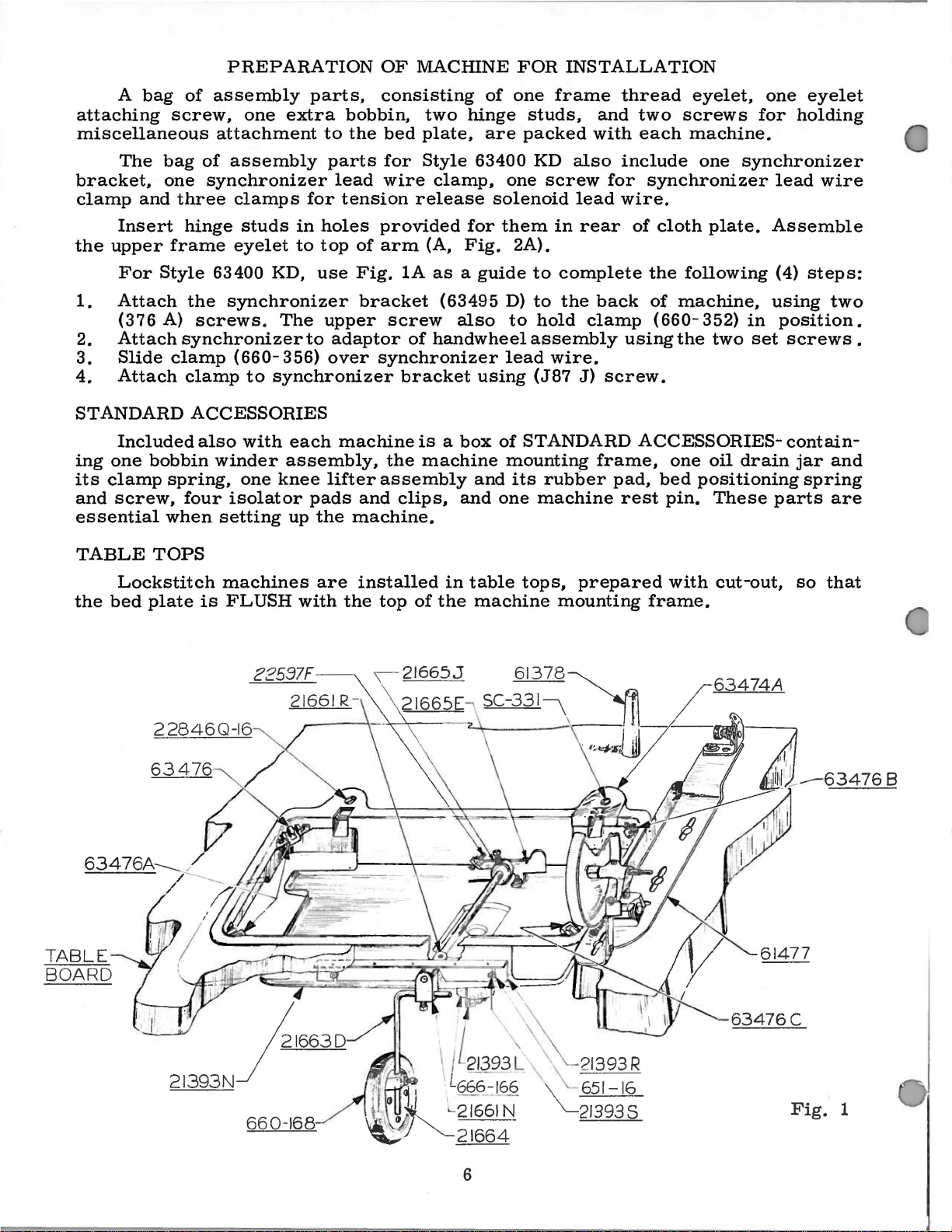
Insert
the
upper
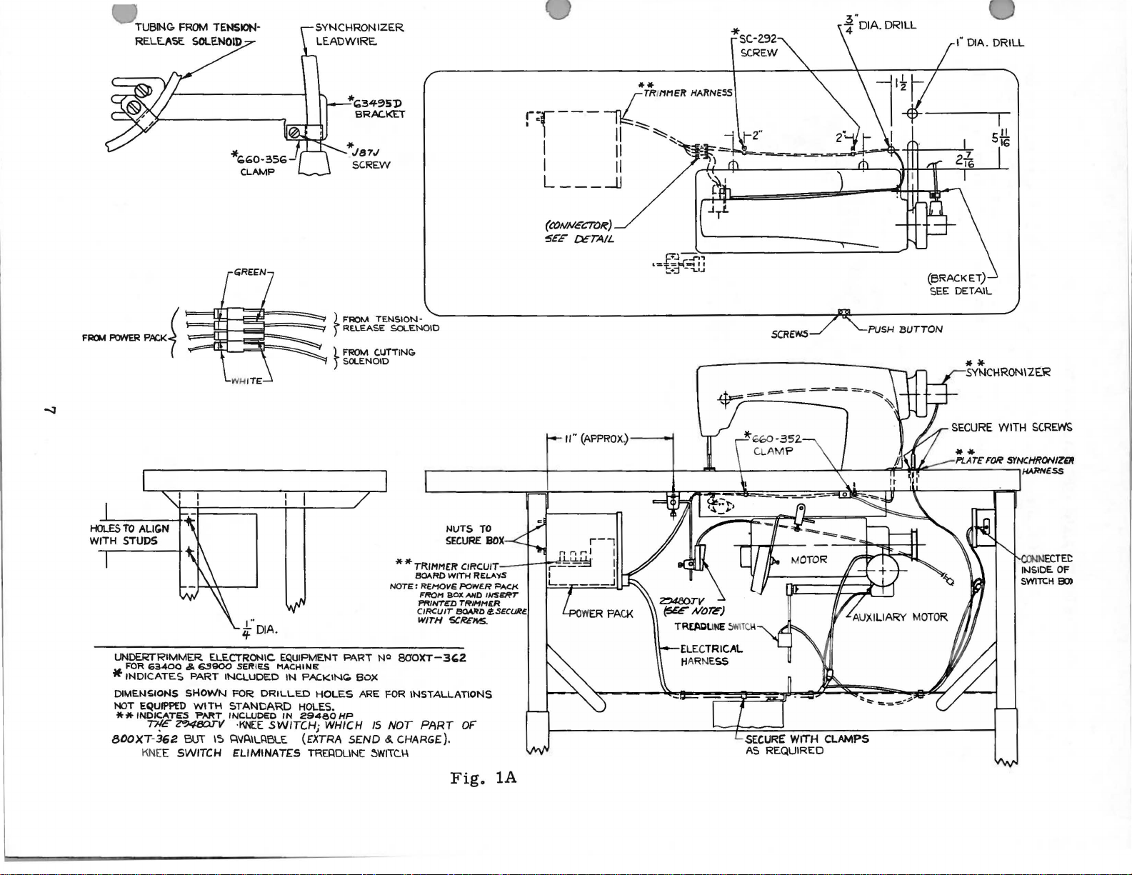
For
1.
Attach
(376
2.
Attach
3.
Slide
4.
Attach
STANDARD
Included
ing
one
its
clamp
and
screw,
essential
TABLE
Lockstitch
the
bed
frame
Style
A)
clamp
bobbin
spring,
when
TOPS
plate
hinge
the
synchronizer
clamp
ACCESSORIES
four
studs
eyelet
63400
synchronizer
screws.
(660-
to
also
with
winder
one
isolator
setting
machines
is
FLUSH
in
to
KD,
The
356)
synchronizer
each
assembly,
knee
up
with
holes
top
use
upper
to
adaptor
over
lifter
pads
the
are
provided
of
arm
Fig.
bracket
screw
synchronizer
machine
the
assembly
and
clips,
machine.
installed
the
top
(A,
lA
as a guide
(63495
of
handwheel
bracket
is a box
machine
in
of
the
for
them
Fig.
also
using
of
and
and
one
table
machine
in
rear
2A).
to
complete
D)
to
the
to
hold
assembly
lead
(J87
STANDARD
mounting
its
machine
tops,
clamp
wire.
J)
rubber
prepared
mounting
of
cloth
the
back
frame,
of
machine,
(660-
using
screw.
pad,
rest
the
ACCESSORIES-
one
bed
pin.
with
frame.
plate.
following
352)
in
two
set
oil
drain
positioning
These
cut-out,
Assemble
(4)
steps:
using
position.
parts
two
screws
contain-
jar
and
spring
are
so
that
.
TABLE
BOARD
22846Q-16
63476
,,
.
21393N
}16630
6
?1393R
\
'--
651-16
\_21393S
Fig.
1
Page 7
.
TUBING
RE.LE.ASE.
FROM
SOLENOID
TENSION·
CLAMP
---~r~
...:J
.,..(;34~5))
BRACKET
*Jsu
SCREW
L FROM TENSION-
)
RE.L£ASE
)_
FROM
)
SOLENOID
SOLENOID
CUTTING.
II''
(APPROX)
E~~,
':::~<~u
-------4
*sc.-2.92
SCREW
SCREWS
PUSH
(BRACKET)
SEE DETAIL
BUTTON
I"
DIA.
DRILL
NUTS
TO
SEGUR£
BOX
* * TRIMMEit CIRCUIT I 1'::':
Ba.\RD
WITH
R£1.AYS
BOX
'iiCREMS.
l='ACI<
MD
IWSeRT
TRIMHiiR
SOARD /l.SECURE.
OF
Fig.
lA
r·
iF
DIA.
UNDERTRIMMER ELECTRONIC
FOR
63-400 & SS900
*INDICATES
DIMENSIONS
NOT
EQUIPPED
**INDICATES
77fE'
800XT-362
KNE
E SWITCH
PART
SHOWN
WITH
~BDTV
BUT
SE,IES
INCLUDED
FOR
DRILLED
STANDARD
'PART
INCLUDED
·KNEE
IS
Q'IP.IL~BLE
ELIMINATES
EQUIPMENT
MACHINE
IN
PACKIN<;.
HOLES.
IN
29480HP
SWITCHj
(EXTRA
TRE~DLINE:
HOLES
WHICH
NOTE:
PART
NQ
80'0XT-3c;Z
BOX
ARE
FOR INSTALLATIONS
IS
NOT
SEND&.
CHARGE).
~WITC.\-1
REMOVE POWE.R
Ff't0/'1
~INT~D
CIRCUIT
WITH
PART
N
ECTE.t:
flJSIDE.
SWITCH
OF
EDl
Page 8
·
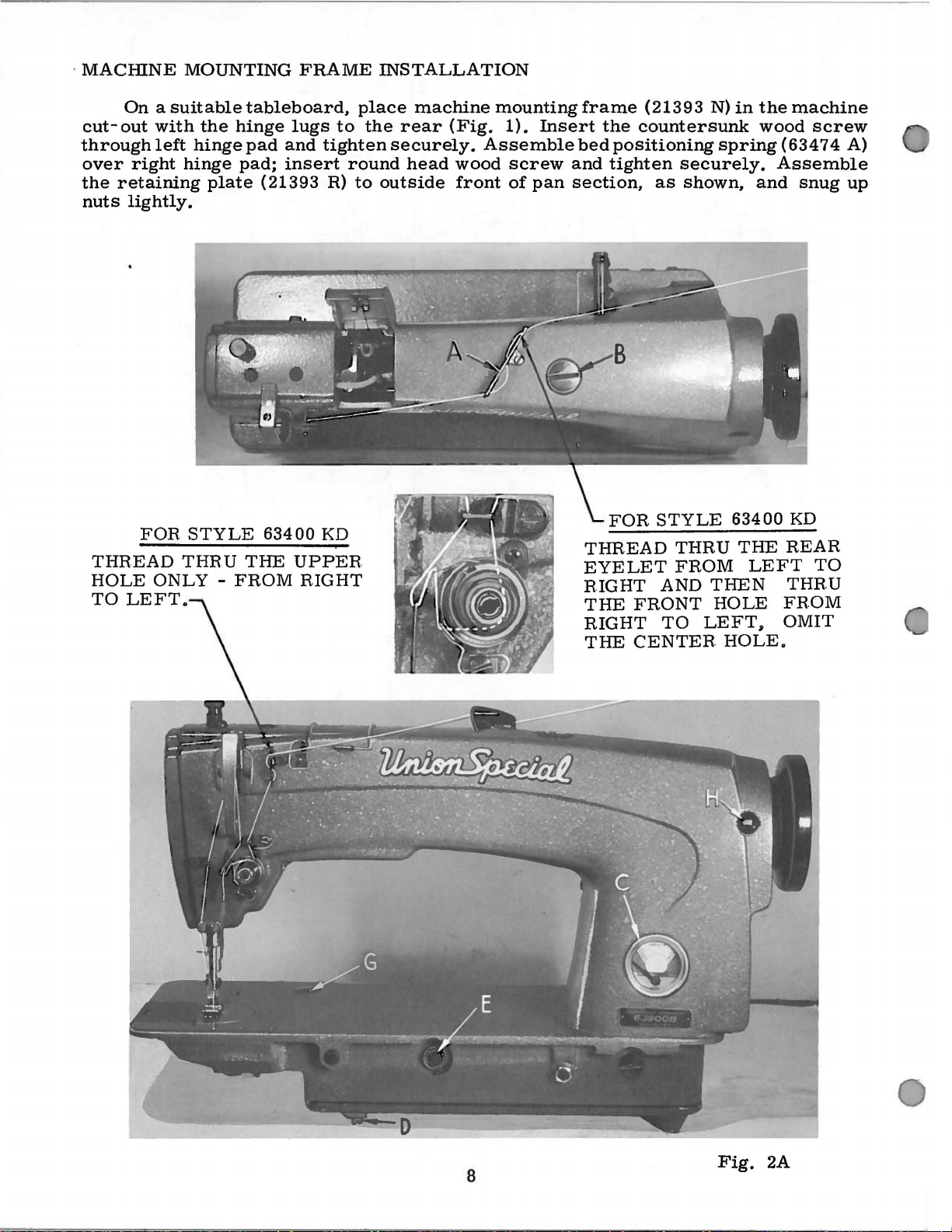
MACinNE
On
cut-out
through
over
the
nuts
right
retaining
lightly.
MOUNTING
a
suitable
with
the
left
hinge
hinge
plate
FRAME
tableboard.
hinge
pad;
pad
(21393
lugs
and
insert
place
to
the
tighten
round
R)
to
INSTALLATION
machine
rear
securely.
head
outside
(Fig.
Assemble
wood
front
mounting
1).
screw
of
Insert
pan
frame
the
bed
positioning
and
tighten
section.
(21393
N)
countersunk
spring
securely.
as
shown.
in
the
wood
and
machine
screw
(63474
A)
Assemble
snug
up
FOR
THR.EAD
HOLE
TO
ONLY-
LEFT
STYLE
THR U THE
634 00 KD
FROM
UPPER.
RIGHT
FOR
THREAD
EYELET
RIGHT
THE
RIGHT
THE
FRONT
CENTER.
STYLE
THR U THE
FROM
AND
TO
THEN
HOLE
LEFT,
HOLE.
63400
LEFT
KD
REAR
TO
THRU
FR.OM
OMIT
8
Fig.
2A
Page 9
MACHINE
MOUNTING
FRAME
INSTALLATION
(Continued)
Place
1/16
retaining
of
as
but
lifter
maximum
within
raises
BOBBIN
located
when
allow
The
against
is
Catalog
inch
the
board
Tip
shown.
must
Before
rod
the
approximately
The
in
the
pulley
described
sewing
clearance
plate
the
not
WINDER
bobbin
directly
operation.
the
No.
smartly
and
machine
All
end
bind.
the
machine
should
lift
of
head.
mechanism
of
the
belt
under
121
head
tighten
back
play
be
adjusted.
the
presser
This
winder
M.
in
front
The
winder,
to
wind
''Winding
may
5/16
in
the
between
upward
locking
against
of
the
is
put
be
inch.
should
of
base
to
be
when
the
frame
the
with a hammer
nuts
cross
into
The
bar
done
be
the
of
the
moved
bobbin.
the
mounting,
cloth
securely.
the
rest
shaft
production,
left
stop
and
its
by
setting
secured
sewing
winder
closer
in
operation,
ReRulation
Bobbin , under
plate
to
pin,
and
should
screw
parts
the
to
the
machine
has
two
to
or
and
after
edge
insure a good
assemble
be
taken
the
bell
(22597
do
not
stop
table
belt
elongated
farther
should
and
OPERA
being
and
the
up
crank
F)
interfere
screw
top
and
will
away
exert
operation
TOR1 S
sure
frame
grip
the
knee
by
the
(21665
should
so
th3;t
so
that
bear
attaching
from
only
of
there
sides,
on
the
press
cone
J)
be
set
with
INSTRUCTIONS
moving
the
its
pulley
against
belt
enough
the
bobbin
underside
assembly
bearings
of
so
presser
holes,
as
pressure
is
about
rap
the
knee
that
parts
will
the
which
needed.
winder
the
,
the
bar
be
belt
in
I
BELTS
These
PREPARATION
Once
1.
Wire
leg
2.
Attach
Drill
3.
Attach
4.
Secure
using
clutch
5.
Connect
release
green.
6.
Assemble
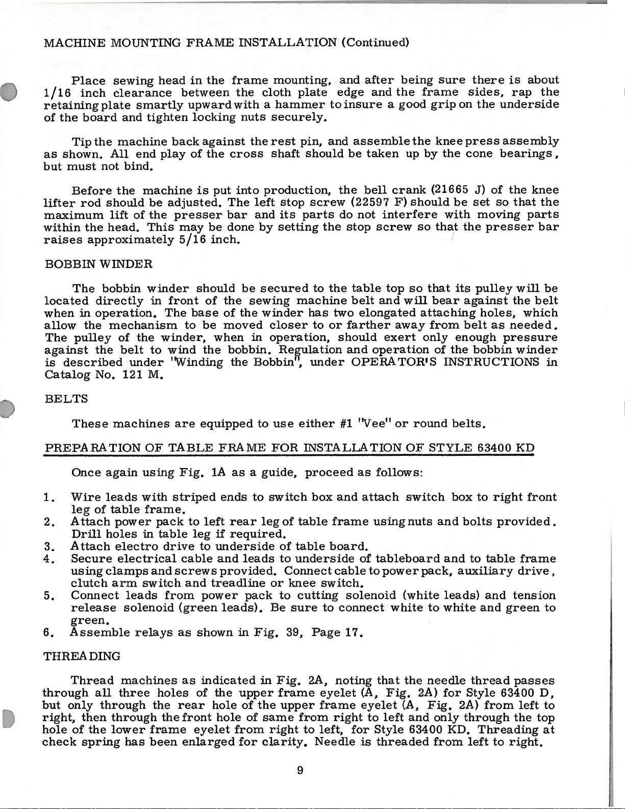
THREADING
Thread
through
but
only
right,
hole
check
then
of
spring
machines
again
leads
of
table
power
holes
clamps
arm
all
through
through
the
lower
electro
electrical
solenoid
machines
three
OF
using
with
frame.
in
switch
leads
relays
has
are
TABLE
striped
pack
table
drive
and
screws
from
holes
the
the
frame
been
equipped
Fig.
(green
as
rear
1A
to
left
leg
to
underside
cable
and
treadline
power
shown
as
indicated
of
the
hole
front
eyelet
enlarged
to
FRAME
as a guide,
ends
if
and
provided.
hole
to
rear
required.
leads
pack
leads).
in
Fig.
upper
of
the
of
from
for
use
FOR
switch
leg
of
of
to
Connect
or
knee
to
Be
sure
39,
in
Fig.
frame
upper
same
right
clarity.
either
INSTALLATION
proceed
table
table
underside
cutting
2A,
from
to
#1
box
and
frame
board.
cable
switch.
to
connect
Page
noting
eyelet
frame
right
left,
Needle
''Vee"
as
attach
using
of
to
solenoid
17.
(A,
eyelet
to
for
Style
is
or
round
OF
follows:
switch
nuts
tableboard
power
that
Fig.
left
threaded
(white
white
the
(A,
and
63400
pack,
to
needle
2A)
Fig.
belts.
STYLE
box
and
bolts
and
auxiliary
leads)
white
for
2A)
only
through
KD.
from
63400
to
right
provided.
to
table
and
and
green
thread
Style
left
63400
from
Threading
to
KD
front
frame
drive,
tension
passes
D,
left
the
top
right.
to
to
at
9
Page 10
CAUTION!
the
reservoir
Fill
Oil
is
at
to
the
right
is
to
the
stainless
at
1000
fication
Oil
The
dial
in
clockwise
It
is
long
parts.
Run
speed
period,
After
machine
operation
Oil
must
main
reservoir
maximum
of
"OPERATE ' zone,
black
line,
water-white
Fahrenheit
No.
175.
may
be
drained
quantity
the
direction
direction
recommended
be
lubricated
oiling,
slowly
can
has
be
filled
safe
located
straight
in
the
of
oil
of
the
decreases
that a new
replace
for
several
then
been
at
o~erating
drained
before
plug
starting
screw
level
marked
to
the
left
mineral
main
from
supplied
reservoir.
main
arrow
the
reservoir
to
the
(counterclockwise)
oil
machine,
by
removing
head
cover
minutes
be
expected
without
OILING
from
(B,
the
Fig.
when
''FULL".
of
''OPERATE"
oil
of a Saybolt
This
hook
flow.
or
the
as
no
to
distribute
main
to
operate.
2A)
the
needle
is
equivalent
by
removing
is
controlled
one
that
head
further
damage.
reservoir
and
check
Oil
should
zone,
viscosity
increases
has
cover
hand
oil
is
and
to
to
the
marked
to
plug
by
been
oiling
the
before
oillevel
black
be
added
of
90
Union
screw
dial
(E).
the
oil
out
of
oiling
will
various
shipment
at
gauge
line,
when
''LOW".
to
125
Special
(D,
Turning
flow
service
all
the
be
required.
parts.
located
needle
Use
seconds
speci-
Fig.
and
for
moving
and
(C) .
a
2A) .
the
in
a
a
Full
The
adjusting
63400 B
covered
instructions
headings
will
in
that
are
indicate
INSTRUCTIONS
instructions
Catalog
No.
different
the
page
for
Styles
121
M,
from
it
can
the
be
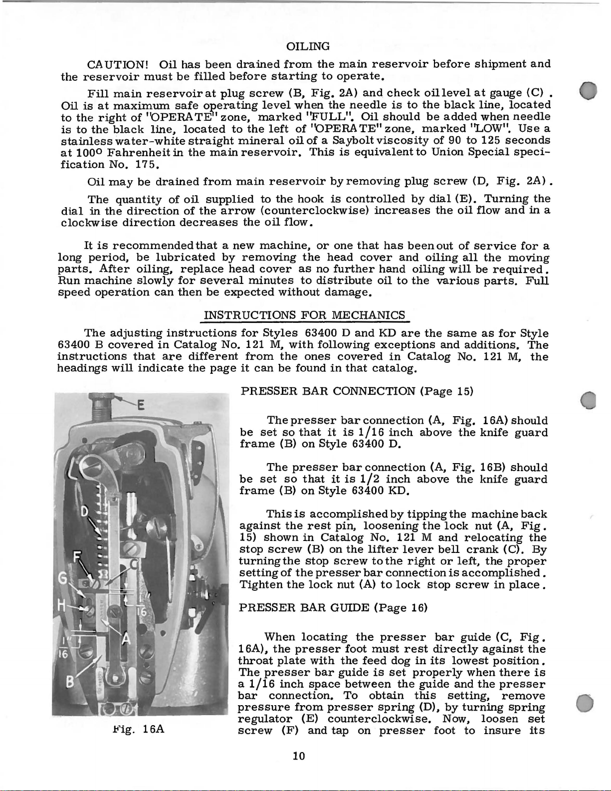
PRESSER
The
be
set
so
frame
(B)
The
be
set
so
frame
(B)
This
against
15)
shown
stop
screw
turning
setting
the
of
Tighten
FOR
63400 D
with
following
ones
found
BAR
presser
that
it
on
Style
presser
that
on
Style
is
accomplished
the
rest
in
Catalog
(B)
stop
the
presser
the
lock
MECHANICS
and
KD
are
exceptions
covered
in
that
in
catalog.
CONNECTION
bar
connection
is
it
1/16
63400
bar
is
inch
D.
connection
1/2
inch
63400 KD.
by
pin,
loosening
No.
121 M
on
the
screw
nut
(A)
lifter
to
bar
lever
the
connection
to
lock
the
and
Catalog
(Page
(A,
above
(A,
above
tipping
the
and
bell
right
or
stop
same
as
additions.
No. 121
15)
Fig.
Fig.
the
lock
the
the
machine
nut
16A)
knife
16B)
knife
relocating
crank
left,
the
is
accomplished
screw
for
M,
(A,
(C).
proper
in
place
Style
The
the
should
guard
should
guard
back
Fig
the
By
.
.
.
PRESSER
When
16A),
throat
The
presser
a
1/16
bar
connection.
pressure
regulator
screw
the
plate
inch
(F)
BAR
locating
presser
with
bar
space
from
presser
(E)
counterclockwise.
and
GUIDE
the
foot
the
guide
between
To
tap
on
10
(Page
presser
must
feed
is
obtain
spring
presser
rest
dog
set
the
16)
bar
directly
in
its
properly
guide
this
(D),
setting,
by
Now,
foot
guide
lowest
when
and
the
turning
to
(C,
against
position
there
presser
remove
spring
loosen
insure
Fig.
the
.
is
set
its
Page 11

PRESSER
BAR
GUIDE
(Page
16,
Continued)
being
the
1116
foot
by
middle
guide.
by
turning
wise.
Set
16B)
so
inches
ment
wire
1.
as
The
should
thread
when
tacking.
release
tension
operation.
down
on
inch
turning
of
its
Now
apply
the
the
needle
that
the
above
merely
required
TENSION
FOR
tension
be
tension
the
arm
assembly
the
throat
dimension,
it
so
slot
and
pressure
presser
thread
under
the
throat
loosen
and
RELEASE
STYLE
release
set
so
when
presser
The
adjustment
and
plate.
center
that
the
retighten
spring
take-
side
plate.
screw
retighten
63400 D
arm
that
it
sewing
foot
the
in-
are
required
Set
the
needle
set
to
the
presser
regulator
up
wire
of
the
wire
To
make
(D),
move
screw.
(Page 1 7)
(G,
will
not
over
is
raised
of
out
position
the
guide
presser
enters
screw
( C, Fi& .
is
adjust-
take-
Fig.
release
seams
for
the
tension
for
proper
the
foot
clock-
4
3{4
up
16A)
the
or
back
of
the
to
in
Fig.
16B
2.
The
is
correct
move
adjust
it,
the
machine.
3.
The
the
conditions.
the
throat
Fig.
Fig.
approximately.
thread
in-
out
tension
stop
tension
tension
holding
18A
16B)
between
position
when
the
assembly
screw
so
assembly
release
screw
The
plate.
(H)
average
Tighten
TENSION
1.
2.
3.
with a set
005
the
tension
of
the
tension
tension
loosen
that
when
arm
(G,
and
release
screw
is
then
assembly
discs
set
the
properly
Fig.
raising
point
(H)
RELEASE
Set
the
tension
centered
Solenoid
release
on
the
plunger
pin
and
trude a minimum
If
adjustment
or
out
by
loosening
and
Tension
screw
inch
clearance
moving
stop
release
in
bracket.
discs.
are
in
screw
flange
set.
16A)
should
or
being
securely.
(Page
assembly
check
pin
the
end
of
is
required
set
screw
solenoid
between
line
with
located
of
the
Tighten
lowering
5116
1 7)
FOR
spring
(E,
of
1 I 3 2
inch
screw
(B,
is
Solenoid
it
and
the
tension
under
tension
assembly
set
now
be
positioned
the
arm
inch
of
STYLE
so
that
the
eyelet
Fig.
16B)
solenoid
to a maximum
move
tension
located
Fig.
18A)
secured
plunger
the
tension
arm
screw
to
presser
63400
tension
(A,
Fig.
must
plunger
post
under
as
required.
to
flat
pin
release
post
of
machine
rests
under
by
suit
foot
KD
18A).
touch
pin
of
assembly
machine
of
bushing
(E)
is
eyelet.
against
arm
loosening
the
sewing
lift
above
discs
tension
must
1 I 16
pin
pro-
inch
to
have
without
To
and
of
are
.
in
arm
(F,
11
Page 12

TENSION
RELEASE
(Page
1
7}
FOR
STYLE
63400 KD
(Continued)
4.
This
solenoid
solenoid
solenoid
thereby
The
manual
release
The
raising
point
Tighten
NOTE:
of
Check
is
the
can
plunger
should
plunger
opening
thread
tension
or
lowering
between
screw
Head
slot
the
oil
be
tension
tension
securely.
oiler
in
the
gauge
accomplished
pin
and
the
then
be
slipped
pin.
the
release
1/4
connecting
Care
tension
release
when
cam
to
suit
to
5/16
bracket
to
be
with
the
must
sure
plate
throat
are
The
in
by
placing
end
of
tension
onto
bushing
should
disc.
cam
the
can
sewing
inch
rod.
it
ADDITIONAL
The
insert,
fastened
throat
the
the
needle
be
After
(G.
presser
be
positioned
of
locate
The
reads
lower
plate
plate
upper
Fig.
presser
to
a.
005
release
and
taken
tightening
foot
conditions.
the
wick
full
knife
which
insert
the
knife,
hole
not
16B)
is
needle
must
and
INSTRUCTIONS
63400
(A,
also
fits
throat
and
insert
and
in
the
inch
spacer
moved
to
set
should
raised
by
loosening
The
foot
lift
bar
contact
operates
D AND KD
Fig.
contains
onto
plate
must
the
throat
pin.
in
exert
screw
be
set
for
average
above
link
oil
freely.
28)
is
the
throat
seat
be
needle
plate
between
The
until
too
so
back
screw
the
wick
the
needle
FOR
built
the
needle
with
in
must
insert.
the
tension
it
contacts
much
remove
that
tacking.
(H)
tension
throat
in
STYLES
into
plate
two
line
and
be
head
release
pressure
spacer.
it
will
and
then
release
plate.
the
center
bearings
the
throat
hole.
and
both
screws
square
centered
of
the
not
.
The
.
left
or
be
set
allow
knife
pressure
to
gaging
(H),
upper
If
get
To
that
the
is
the
knife
Fig.
28
right
so
additional
engage
lever
as
it
is
snug
pilot
engaged
adjusting
desired
(G).
will
release
must
required.
against
of
the
to
the
pressure
screw
cutting.
the
upper
Just
release
holder
attached
vertically
up
upper
edge
the
loosening
to
With
upper
cutting
(F)
knife
above
or
disengage
freely
The
upper
(C)
to
by
or
down
knife
should
lower
The
the
the
knife
position.
on
the
may
the
knife.
upper
upper
the
upper
lower
to
strike
upper
be
merely
upper
the
with a snappy
knife
with
the
upper
loosening
as
is
in
extend
screws
knife
knife,
knife
turned
press
knife
upper
(B)
two
screws
knife
screws
required.
its
lowest
1/64
knife
bar
knife
on
can
(E)
that
and
in
but
not
top
is
in
slightly
downwardly
engaging
knife
movement;
is
attached
and
bar.
Tighten
position,
inch
below
be
hold
then
its
lowest
to
have
of
the
required
lever
by
pushing
the
The
(D)
and
moved
the
moving
enough
lower
to
against
on
the
is
no
to
the
upper
holder
knife
movingthe
screws.
the
the
horizontally
upper
the
position,
knife
get a clean
the
upper
the
in
this
bind
in
can
front
cutting
knife
holder
pressure
when
upper
release
button.
is
permitted
turn
be
moved
When
cutting
edge
holder
to
it
should
the
cut, a
knife
knife
button
knife
is
knife
the
of
by
the
to
top
en-
The
.
NOTE:
CATALOG
THE
APPLY
REMAINDER
ONLY
TO
OF
THE
STYLE
ADJUSTING
63400 KD.
12
INSTRUCTIONS
IN
TillS
Page 13

TRIMMER
ADJUSTMENTS
1.
2.
Remove
assembly
There
pivot
can
release
end
be.
Position
side
to
loosen
are
bushing
finger
should
carrier
be
made
play
of
the
see
that
the
parallel.
(Fig.
from
lever
or
upper
arm
the
finger
(F)
the
positioning
machine
be
no
(A,
by
loosening
(C)
and
relieving
knife
of
the
lower
set
A
good
located
31).
Adjust
the
knife
D
CAUTION:
adjustment
and
bind
or
Fig.
lower
29).
screw
taking
the
bind
(D)
parallel
positioning
knife
screw
starting
approx.
lower
and
finger
proceed
shake
This
(B)
up
as
is
parallel
(E)
and
point
90°
knife
knifeturnflange
counterclockwise
Be
sure
or
parallel
and
as
in
lower
adjustment
on
the
the
excessive
the
case
with
finger.
turn
would
to
the
until
bushing
follows:
the
with
the
right
it
adjustment
knife
knife
pivot
may
left
Check
the
eccentric
be
to
side
just
screw
to
upper
have
contacts
raise
is
the
of
(G,
not
will
knife.
bushing
pinhole
the
arm
the
upper
Fig.
it.
turned
have
Fig.
29)
29
If
this
is
(F)
until
the
in
the
of
the
positioning
knife.
clockwisetolower
while
to
be
checked.
making
not
so,
knives
eccentric
To
adjust
this
4.
Fig.
recess
assembly
allowing
outside
edge
Locate
Fig.
parallel
cutting
cutting
pivot
a
when
in
of
32)
release
1/3 2 inch
knife
position.
30
(B)
and
attaching
1/32
edge
bobbin
the
cutting
as
far
with
solenoid
solenoid
return
The
should
ing
finger
out
of
tioning
ments
3.
Assemble
machine.
and
the
Fig.
tioning
bobbin
tighten
inch
of
the
lever
clearance
clearance
projection
case
solenoid
forward
line
lever
plunger
(D),
spring
lower
not
the
cutting
finger
loosen
knife
finger
12A)
the
finger
screws
recess
as
of
(B)
(C),
so
to
(A,
knife
extend
(B).
finger
and
feed.
contacting
that
be
beyond
As
edge
as
indicated
screws
positioning
Adjust
assembly
recess
on
the
case
and
securely,
between
the
(Fig.
bracket
possible
With
adjust
there
maintained
Fig.
(A,
the
(A,
the
posi-
into
holder
knife
inside
12A).
33)
the
lower
(C)
bobbin
by
is
the
the
(A,
and
the
the
the
is
is
Fig.
left
knife
must
at
Fig.
finger
turning
at
the
30)
side
coincide
point
31)
case
top.
in
its
of
moves
(D).
and
position
and
holder
the
bobbin
Place
Fig.
extreme
the
arm
to
the
at a point
To
make
knife
positioning
the
12A
left
of
the
right,
of
these
knife.
assembly
case
holder
projection
position
position-
the
run
the
posi-
adjust-
into
finger
until
(A,
13
Page 14

TRIMMER
5.
Adjust
the
left
the
the
lower
corner
needle
ADJUSTMENTS
lower
knife
(E,
slot
knife
is
Fig.
in
in
the
stop
its
30)
bobbin
(Continued)
screw
extreme
is
in
case
right
line
(B,
Fig.
hand
with
holder.
33)
position,
the
left
so
side
when
the
of
Fig.
solenoid
machine
step
5.
7.
Knife
have
To
proper
adjust
loosen
spring
crease
the
tension.
SYNCHRONIZER
(a)
Rotate
until
the
deflector
needle
31
bracket
or
position
return
spring
tension
tension
screw
bracket
tension
(C)
(D)
or
handwheelin
needle
plate ( C,
on
the
up
stroke
CAUTION:
lower
sure
6.
Be
sure
the
bobbin
extreme
not
make
NOTE:
are
removed
changed,
(A,
Fig.
to
cut
threads.
of
to
knife
and
to
the
the
left
return
move
right
to
decrease
ADJUSTMENT
operating
clearance
Fig.
12A)
of
the
direction
cut
on
needle
knife
knife
the
right
If
from
check
33)
spring
tension
to
in
the
Be
sure
stop
when
does
not
spring
case
holder
hand
contact,
positioning
to
in-
the
rotating
bar.
cutting
making
hit
the
retainer
when
position.
bend
retainer
hook
solenoid
hook
wire
the
finger
assembly
this
adjustment.
point.
(B,
lower
If
the
wire
assembly
Fig.
lever
Fig.
spring
to
32
is
in
contacts
31)
knife
suit.
or
line
Also
contacts
is
wire
cutting
with
in
does
the
be
its
the
(c)
Fig.
set
screws
required.
The
needle
bottom
of
handwheel
screw
third
until
plastic
(D)
band
its
band.
33
(C)
in
positioner
stroke.
until
at
end
from
brush
(b)
synchronizer
should
If
not,
it
is
at
of
synchronizer
left
(E)
is
in
the
At
brass
the
Fig.
flush
front
brush
To
adjustment
tion
deflector
described
(a),
position
with
bottom.
in
operating
middle
this
left
34)
edge
holder
make
needle
then
and
power
Then
of
time
contact
band
should
with
of
bar
plate
in
loosen
move
needle
off
rotate
loosen
and
rotate
direction
the
black
14
the
(A ,
be
the
the
(B) .
this
posi-
and
as
step
as
of
at
Fig.
34
Page 15

SYNCHRONIZER
(d)
The
needle
or
If
in
top
end
from
middle
on
positions
needle
1/8
not,
operating
of
of
synchronizer
left
power
(Continued)
positioner
thread
inch
with
its
of
take-up
from
power
direction
stroke.
(F)
the
and
of
the
ADJUSTMENT
should
at
top
the
top
ofits
off
rotate
until
Then
and
until
black
check
needle
loosen
rotate
its
brush
plastic
the
bar.
position
of
its
up
handwheel
it
is
screw
fourth
is
band.
up
and
stroke
stroke.
at
the
band
in
the
Turn
down
at
(a)
(b)
(c)
CLUTCH
Set
needle
Adjust
that
washer
Close
there
needle
clutch
treadle
treadline
is
positions
ARM
(B)
no
in
work.
arm
will
is
to
contact
SWITCH
spring
return
be
approximately
switch
between
up.
Tighten
(a)
(b)
ADJUSTMENT
(A,
Fig.
to
stop
and
loosen
it
nut
ADJUSTING
Depress
indicates
Adjust
1/16
Loosen
Motor")
mately
top
described
(win&
and
(D)
to
on
35)
1j2
clutch
clutch
lock
one
right
so
nut
inch
lever
the
microswitch.
to
maintain
CLUTCH
treadle
switch
so
1/8
inch
screw
just
enough
full
end
above.
from
unit
is
open.
that
travel
(E,
turn.
of
motor,
Tighten
end
switch
setting.
until
clutch
before
Fig.
to
unlock
Adjust
Fig.
of
stud).
adjusting
Then
one
click
arm
35)
(where
it,
screw
until
lock
screw
35
tighten
is
has
clutch
which
located
clutch
screw
approximately
(E).
screw
heard,
is
it
says
is
is
engaged
(C),
which
engaged.
"Lock
approxi-
near
until
until
the
as
2.
Thread
3.
Form
(63470
CAUTION!
stop.
of
Premature
Fig.
thread
Move
tube.
36
wiper
M).
Be
lever
wiper
Thread
thread
sure
failure
1.
(63470
wire
wiper
wiper
to
of
solenoid
CAUTION!
lever
one
THREAD
Position
thread
thread
take-up
E)
(63470
hook
guide
loosen
click
must
must
(63470
set
will
switch
wiper
wiper
V)
result
Clutch
must
WIPER
thread
is
at
return
for
not
M)
screws
must
is
closed
be
heard
ADJUSTMENTS
wiper
guide
wire
the
free
prevent
if
(63470
catches
top
of
with a snap
movement
so
that
when
it
is
not
adjusting
15
not
or
auxiliary
before
bracket
M),
the
its
stroke.
when
solenoid
hook
does
allowed
engage
clutch
(63470
so
that
needle
released.
in
thread
from
not
thread
to
return
when
motor
is
L)
and
the
hook
thread
wiper
returning
stop
against
wiper
completely.
clutch
running;
engaged
adjust
of
the
when
the
guide
to
its
end
lever.
.
Page 16

INSTALLATION
OF
INCHING
SWITCH
When
be
sure
treadle
the
needle
enables
with
trimmed
the
installing
to
remove
is
heeled
will
the
operator
needle
the
threads.
inching
jumper
while
position
to
out
of
switch,
wire
between
socket
ing
the
or
it
properly.
S h o u 1 d t h e
switch
later
(A,
Fig.
placed
tioning
up.
PUSHBUTTON
If
which
front
board,
cutter
chronizer
T h e r e
the
pushbutton
up
without
readjust
the
or
work,
(Amco
(A,
Fig.
pin
# 2
and
(B)
before
inching
will
date,
or
unit
thepushbutton,
is
edge
band
for
realign
not
be
removed
the
36)
the
will
mounted
is
depressed,
is
e,
is
trimming.
but
without
jumperwire
must
needle
not
FUNCTION
of
of
interrupted
depressed,
the
No. M6665)
36)
located
pin
# 3
on
connect
switch
function
inching
be
position
on
the
the
w h
en
garment
having
plug
at
re-
posi-
the
table
the
syn-
the
This
-
a
.
TREADLINE
To
adjust
loosen
more
moved
located
can
bushing
the
adjustment
and
to
obtain
If
more
be
compressed
(C)
SWITCH
the
two
Allen
the
three
or
less
up
or
length
set
is
necessary
the
desired
pressure
more
down.
ADJUSTMENT
of
the
pitman
screws
bushings
or
less
in
the
inside
length.
is
required
accordingly
rod
the
cover
the
(A,
back
must
switch
Fig.
panel.
be
when
by
37)
If
rere-
heeling
moving
the
the
treadle
pitman
Fig.
rod
37
the
spring
spring
(B)
tension
16
Page 17

TREADLINE
SWITCH
ADJUSTMENT
(Continued)
If
more
for
actuating
micro-switch
(E),
must
so
that
uate
switch
bevel
(D).
This
stop
bushing
the
be
only
micro-switch.
should
on
the
is
travel
the
is
trim
required
cycle
actuator
lowered.
enough
not
travel
be
allowed
micro-switch
accomplished
(E).
(D)
Care
is
The
by
in
the
the
two
bushings,
and
stop
should
provided
roller
to
ride
actuator
adjustment
treadle
bushing
be
taken
to
act-
on
the
over
the
bushing
of
the
.
winding
fuses
the
solenoid
ofthe
output
and
Fig.
38
transformer.
side
the
relay
of
the
coil
The 5 AMP
rectifier
control
circuit
FUSING
The
feature
two
are
1
1/4
AMP
blow
AMP
panel
fuse
fuse
fuses
positioner
AMP
fuse
chassis
fuse
(B,
for
the
thread
(24
THE
POWER
power
pack
consisting
of
the
slow
at
250
rated 5 AMP
(A,
Fig.
the
auxiliary
circuit
(A,
Fig.
fuses
Fig.
the
38)
wiper
VDC).
PACK
incorporates
of
three
blowing
V
and
type
the
at
38)
located
motor
components.
39)
located
AC
input
located
under
solenoid
a
(3)
fuses
and
of
are
third a straight
250
V.
The
in
the
as
well
The
on
top
for
the
primary
the
chassis,
(30
VDC)
safety
which
rated
1
1/4
front
as
the
1
1/4
of
the
cutter
Fig.
39
17
Page 18

Before
satisfaction
and
ficial
is
not
to
this
you.
machine
and
durability
positioning
NOTE:
left
the
properly
A.
C.
factory
at
all
voltage
it
times.
see
the
200-250
was
If,
chart
adjusted
however,
below
volts.
and
the
for
inspected
needle
suggestions
positioner
so
as
which
to
give
has
you
been
may
the
utmost
readjusted
prove
bene-
Unit
Unit
cond
not
C
ondition
does
positions
position,
position
not
up
down
position
in
but
does
TYPICAL
se-
NEEDLE
Bad
Synchronizer
plugged
broken
Dirty
Treadle
in
properly
No
input
Burnt
and
Tight
en
teeth
The
opening
POSITIONER
Causes
fuse
in
brushes
jack
power
or
armature
fiber
on
treadle
jack
properly
not
(220
dirty
gear
or
fiber
switch
not
or
plugged
V)
brushes
brok-
gear
is
not
PROBLEMS
Replace
Check
chronizer
if
Clean
Clean
le
Check
Clean
es
Take
housing
cessive
or
T h e
down
the
and
connection
necessary
or
connection
jack
input
armature
or
replace
fiber
replace
unit
the
power
then
Cures
fuse
jack
replace
gear
and
stock
w
first
back
(A,
or
power
or
out
remove
from
ill
time
is
turned
on
Fig.
38)
of
syn-
replace
brushes
of
tread-
brush-
of
bell
ex-
hub,
position
after
off
again
Unit
blows
few
hours
days
Unit
keeps
at
an
inching
Auxiliary
while
with
clutch
main
the
fuse
or
on
speed
motor
is
motor
every
every
stitching
runs
engaged
few
Grounded
bolt
touching
Oil
saturated
Tight
Operator
treadle
Synchronizer
plugged
Damaged
auxiliary
Synchronizer
handwheel
Very
Clutch
opening
fiber
excessively
in
motor
loose
arm
armature,
field
armature
gear
fluttering
j a c k
properly
field
''V"
coil
1 o o s e
belt
switch
is
tie
not
on
not
in
Insulate
move
Clean
Take
bell
excessive
Caution
Check
chronizer
Replace
Tighten
handwheel
Reposition
Adjust
properly
short
armature
fiber
housing
connection
clutch
tie
bolt
andre-
gear
and
remove
stock
operator
auxiliary
synchronizer
jack
motor
arm
from
of
to
switch
out
hub
syn-
motor
on
suit
of
Clutch
arm
switch
broken
18
Replace
switch
Page 19

TYPICAL
NEEDLE
POSITIONER
PROBLEMS
(Continued)
Condition
Unit
positions
A u x
ilia
very
hot
Unit
positioning
when
blows
fuse
r y
is
slowly
motor
fuse
one
first
runs
after
time, .not
put
in
Armature
mutation
shorted
Tight
Improper
arm
Operator
arm
Grounded
Lead
Brush
against
fiber
switch
switch
rubbing
Causes
has
poor
or
and
dirty
gear
setting
fluttering
field
in
holders
armature
com-
is
partly
of
clutch
clutch
coil
armature
brush
Dress
dressing
Take
bell
excessive
Adjust
properly
Caution
Check
sula
Isolate
Remove
iary
brush
fiber
housing
with
te
tie
motor
holders
Cures
armature
stone
stock
clutch
operator
tester
bolt
from
end
cap
and
gear
and
armature
from
arm
of
relocate
out
remove
switch
and
auxil-
with
of
hub
in-
Auxiliary
turn
over
know
Unit
power
power
does
to
motor
although
is
feeding
.not
solenoids
will
.not
you
provide
it
Bad
armature
Tight
Solenoids
ed
Bad
Diodes
No
secondary
er
leads
fiber
to
power
relays
shorted
voltage
blue,
gear
are
pack
from
on
gray
brushes
not
connect-
out
trimmer
transform-
and
white
Replace
iary
motor
Take
fiber
housing
cessive
Check
leads
Check
3,
Fig.
Replace
circuit
Check
former,
place
transformer
brushes
gear
and
stock
c o
.n
relays
39)
diode
board
output
if
defective-
remove
from
n e c t
(Nos.
with
o.n
of
on
auxil-
out
of
hub
ions
1, 2,
tester
trimmer
trans-
bell
ex-
on
re-
19
Page 20

Before
bility
for
suggestions
at
this
all
machine
times.
which
left
If,
however,
may
the
prove
factory,
the
beneficial
it
was
trimmer
adjusted
has
been
to
you.
and
inspected
readjusted
and
so
is
as
not
to
give
trimming
the
utmost
properly.
satisfaction
see
the
and
chart
durabelow
Both
Needle
thread
Bobbin
thread
threads
thread
cut
thread
cut
Condition
not
cut
not
cut,
not
cut,
but
but
bobbin
needle
TRIMMER
Solenoid
Lower
enough
Lower
wipes
Lower
slip
Spring
ing
catching
Lower
enough
Hook No. 29474 R
Bobbin
in
bobbin
Needle
big
TROUBLESHOOTING
Causes
not
working
knife
not
to
the
right
knife
too
when
case
position
knife
to
right
thread
case
in
been
too
behind
knife
does
throatplate
threads
knife
off
retainer
bobbin
hole
or
has
far
far
back,
wire
holder
not
or S used
not
threaded
altered
moving
forward,
knife
returns
not
contact-
move
far
threads
when
far
thru
is
too
in
Check
lead
Make
continuity
Reset
stop
Relocate
on
radius
Relocate
Bend
spring
Adjust
setting.
noid.
Operate
off,
to
determine
lever
is
and
then
necessary
Use
only
Thread
throat
Use
needle
hole,
Cures
connections
check
screw
knife.
Check
knife
retainer
stop
screw
Check
contacting
reposition
No. 29474 T hook
properly
plate
if
wire
to
position
machine
if
solenoid
stop
with
available
solenoid
for
nicks
to
suit.
standard
of
sole-
with
belt
pivot
screw
smaller
if
Lower
the
way
Needle
random
Needle
Bobbin
does
knife
thread
lengths
unthreads
thread
breaks
not
tears
of
when
return
and
starting
starting
all
leaves
tail
Not
enough
return
and
rough
te.nsion
more
spring
Lower
much
Too
tension
needle
thread
Tension
Needle
tioned
properly
Needle
big
Bobbin
Overspin
much
Too
tension
tension
spring.
thread
knife
rubbing
knife
and
excessive
thread
pull-off
disc
thread
hole
in
thread
on
bobbin
knife
Dense
on
eyelets
at
not
open
take-up
at
throat
too
on
lower
will
knife
hook
return
cone
top
plate
short
thread
return
knife
material
require
return
point
spring
friction
and
not
posi-
of
stroke
is
spring
in
in
too
Increase
return
to
the
right
Raise
lower
Unthread
the
right
crease
spring
pull-off
Check
setting
solenoid
tion
of
Check
take-up.
of
the
top
throat
Use
needle
See
bobbin
Check
wind
bobbin
Decrease
spring
slightly,
et
to
the
tension
spring
knife
some
of
the
tension
slightly.
at co.
nes
and
this
solenoid
position
Must
of
its
plate
hole,
if
thread
of
in
bobbin
tension
left
on
by
moving
of
the
tension
on
knife
Check
of
tension
electrical
of
needle
be
within
upstroke
with
available
breaks
bobbin
case
on
knife
by
moving
lower
bracket
eyelets
post.
release
1/8
smaller
and
holder
knife
Dereturn
thread
opera-
thread
inch
fit
return
brack-
to
of
Sharp
edges
on
T.
C.
S.
of
and
S.
of
needle
lower
back
lower
positioner
circuitry.
NOTE:
Refer
to
information
Amco
or
Quick
regarding
knife.
edges
knife)
Catalogs ·furnished
the
needle
positioner
(Front,
are
with
and
the
point
T.
C.
each
electrical
20
for
Stone
lower
back
edges
lower
guardian
sharp
edges
knife.
are
knife)
maintenance
(Front,
the
ofT.
T.
C.
point
C.
and
S.
and
S.
other
of
of
Page 21

EXPLODED
AND
VIEWS
HIGH
DESCRIPTION
PECULIAR
STYLES
SPEED
OF
63400
LOCKSTITCH
TO
D
PARTS
and
MAC
KD
HINES
21
Page 22

22
Page 23

PRESSER
FEET,
FOR
THREAD TENSION ASSEMBLY, OILING AND MISCELLANEOUS
STYLES 63400 D and
KD
UNLESS OTHERWISE
SPECIFIED
PARTS
Ref.
No.
>,\l
2
3
4
..,
"
6
7
8
9
10
11
12
13
14
15
16
17
18
19
20
21
22
23
24
25
26
27
28
29
30
31
32
33
34
35
36
37
38
39
40
41
42
43
44
45
46
47
48
49
50
51
52
53
54
55
56
57
58
59
60
61
62
63
64
Part
No.
29475
AS
61292 c
61392 F-9
61492 H
109
63453
61492 F
61492 G
61492 E
22560 G
660-269 A
63971 A
666-222
63982 A
90
63982 F
61982
c
61982 D
666-254
63984
c
666-223
63493 G
63493
c
63493 B
666-225
666-224
61985 G
666-228
61985 H
666-246
666-245
c
63470
22513
22766
63970 A
666-241
AD
63487
63493 E
666-214
63482
63482 D
63459 B
22570
63458
63458 A
22585
22775
63420-1/16
63420
63420
63420
63430
51930
61330 B-31
63417
29475 BB
22894
22894 w
22894 v
63401
c
22516 A
73
c
660-219
A-1/8
A-3/16
A-1/4
28
c
C067
D
u
87
A
s
Description
Thread
Take-up
Top
Top
Top
Fell
Wire
Hood
Knife
Head
Oil
Roll
Roll
Bushing,
Roll
Bushing,
Felt,
Felt
Lower
Screw,
Screw,
Needle
Felt
Knife
Oil
Head
Screw,
Presser
Presser
Tension
Screw,
Screw,
Presser
Presser
Presser
Presser
Needle
Mainshaft
Auxiliary
Screw,
Tension
Tension
Tension
Tension
Tension
Take-up
Tension
Tension
Tension
Screw
"Quad"
Lever
Fell
Pad---------------------------------------------------------
Cover
Screw
Spring
Cover
Cover
Baffle,
Spring
Contacting
Driving
Oiler
Supply
Fell,
Fell,
left,
Felt,
right,
for
needle
Pad,
Needle
for
for
Thread
Pad,
Release
Siphon
Oil
Felt----------------------------------------------------------
Cover
Gasket
for
Bar
Screw
Screw
Bar
Pin
Roll
Release
for
for
Foot,
Foot,
Foot,
Foot,
Presser
Spring----------------------------------------------------------Hinge
Bar-----------------------------------------------------------
Screw-----------------------------------------------------------Cork
Spot
Screw-------------------------------------------------------
Set
Screw--------------------------------------------------------
Set
Screw--------------------------------------------------------
Cloth
for
Assembly----------------------------------------------
Nut-----------------------------------------------------Spring
Release
Disc
Spring---------------------------------------------------
Post
Release
Post
Ring------------------------------------------------------
-----------------------------------------------------------
----------------------------------------------------------Clip-------------------------------------------------------
rlinge-----------------------------------------------------Hinge
for
Clip,
Assembly-------------------------------------------------Line
for
for
for
for
lower
needle
for
Head
----------------------------------------------------------
----------------------------------------------------------
head
Guide,
-----------------------------------------------------------
----------------------------------------------------------Lifter
---------------------------------------------------------
tension
presser
Foot
Pin--------------------------------------------------------
-----------------------------------------------------------and
auxiliary
--------------------------------------------------Washer
--------------------------------------------------
----------------------------------------------------Pin
Socket-----------------------------------------------
-------------------------------------------------------
Hood
--------------------------------------------------
Pin--------------------------------------------------
main
shaft
for
fell----------------------------------------------
Fell--------------------------------------------------
Eccentric
-------------------------------------------------------
oil
supply
upper
knife
diverting
Thread
bottom
Pin
Counterweight
mainshaft
for
knife
drive
for
knife
bar
oiling
oil
Eyelet
needle
thread
Pull-up
Tube--------------------------------------------------
cover
Arm,
for
for
for
for
Plate--------------------------------------------------
Bracket-----------------------------------------
of
Bushing
------------------------------------------------
Style
Connection,
for
release
foot
Styles
Styles
Styles
Styles
Shank
cloth
------------------------------------------
----------------------------------------------
assembly
Connecting
line
-------------------------------------------
drive
rocker
rocker
drive
--------------------------------------------from
-------------------------------------------
thread
pull-up
head
-------------------------------------------
---------------------------------------------
63400 D
Style
arm,
----------------------------------------------63400
63400
63400
63400
-----------------------------------------------
Assembly----------------------------------
plate
------------------------------------
Rod
Oiler----------------------------
bearing,
shaft-----------------------------------
rocker
take-up---------------------------------
eyelet-----------------------------------
bracket--------------------------------
for
63400 D
for
D-1/16,
D-1/8,
D-3/16,
D-1/4,
----------------------------------------
left
shaft-------------------------------
--------------------------------------
Style
Style
-----------------------------
shaft
-----------------------------
63400 D
-------------------------------63400
KD-1/16
KD-1/8
KD-3/16-------------------------
KD-1/4---------------------------
------------------------
D------------------------
------------------------
--------------------------
Amt.
Req.
--"" 2
1
1
1
1
1
1
1
1
1
1
1
1
1
1
1
1
2
1
1
1
1
1
1
1
1
1
1
1
1
1
1
1
1
1
1
1
1
1
2
1
3
1
1
1
1
1
1
1
1
1
1
1
1
1
1
1
2
4
1
1
1
1
1
1
1
'~
Same
as
used
on Style 63400 B.
23
Page 24

24
Page 25

THROAT
PLATE,
FOR
FEED
STYLES
DOGS,
63400
D,
KD
TRIMMER
UNLESS
AND
TRIMMER
OTHERWISE
DRIVING
SPECIFIED
PARTS
Ref.
No.
1
2
3
4
5
6
7
8
9
10
11
12
13
14
15
16
17
18
19
20
21
22
23
24
25
26
27
28
29
30
31
32
33
34
35
36
37
38
39
40
41
42
43
44
45
46
47
48
49
50
51
51
52
53
53
54
55
56
57
22557 D
63487
63487
22576
63496
63487
22790 A
39550
63487 u
22894
51773
22881
63487 D
22839
29126
63487 c
22894
60038
63491 B
22894
14077
63487 A
63487 AA
63487
63487 X
63487 K
22581 B
63487 R
63487 L
63487
63487 H
63487 G
63487
63487
63487 F
63487
63487 J
63487 T
22874
63487
22768
6340 5 s
63405
63405
A
63428
63428
63428 C-1/4
63428 C-1/8
63428 A-1/16
A
63487 AC
22564
Part
No.
v
87 u
s
A
E
164
-22
J
y
88
B
DZ
J
18
20
G
J
w
u
87
Q
B
25
87
AE
AE
AF
c
73
J87
J
E
T
C-3/16
376
G
666-186
- 2
- 3
Description
Screw,
Knife
Screw,
Upper
Screw,
Needle
Knife
Shim,
Screw,
Sprin
Knife
Collar,
Stud,
Knife
Knife
Nut,
Washer,
Bearing
Counterweight,
Nut,
Knife
Knife
Knife
Upper
Knife
Screw,
Upper
Screw,
Upper
Knife
Knife
Screw,
Shim, . 002
Shim,
Knife
Upper
Knife
Upper
Screw,
Screw,
Knife
Screw,
Feed Dog,
Feed
Feed
Thro~ Pl
Throat
Throat
Throat
Throat
Screw,
ChipGuard-------------------------------------------------------Screw,
Oil
for
knife
Release Pin--------------------------------------------------------
for
Knife
for
Bar
Bar
Retainer
for
knife
for kni
g,
for
Release
Set
Screw------for
Set
Screw
for
bearing
Rocker
Screw--------------------------------
Drive
Knife
Drive
Set
Screw--------------------------------------------
for
bearing
for
Sleeve
Set
Screw
for
knife
Drive
Return
Return
Knife
Drive
for
Knife
for
Knife
Knife
Drive
Screw--------------------------------------------------------------
Drive
Bar
Retaining Fork-------------------------------------------------
for knife
.003
Driving
Knife-------------------------------------------------------------
Driving
Knife
Set
Screw-----------------------------------------------------------
for
for
Guide
for
D-
3/16,
D-1/4---------~----------------------------------------------
Dog,
D-
3/16,
D-1/4---------------------------------------------------------
Dog,
ate--------------------------------~---------------------------
Plate
KD-
3/16
(. 073
Plate
KD-1/
4 (. 073
Plate
KD-1/
8 (. 073
Plate
KD-1/16
Felt
(.073
for
for
Plug,
return
upper
Engaging
knife
bar
Oiling
bar
fe
return
knife
release
Button-------------
knife
drive
------------------
Shaft
Eccentric
Eccentric
sleeve
bearing
---------------------for
----------------------------------------------------------drive
Rocker
Spring
Spring------------------------------------------------------
Bar---------------------------------------------------------
Ferrule
knife
drive
Clamp
upper
Drive
Connecting
Pin
Spring---------------------------------------------------
bar
inch
thick,
inch
thick,
Arm
Pin--------------------------------------------------------
Holder------------------------------------------------------
upper
knife
guide
Frame
feed
dog------------------------------------------------------
marked
marked
marked
Insert,
inch
Insert,
inch
Insert,
inch
Insert,
inch
throat
chip
guard----------------------------------------------------
for
spring
knife
engaging
Lever
retainer ---
Bracket------
------------retainer--------
spring
- - rocker
sleeve--------
Driving
Assembly,
stud
sleeve
knife
rocker
Shaft-------------------------------------------------
Bracket----------------------------------------------
----------------------------------------------------ferrule
Plate-------------
knife---------------
Connecting Rod
retaining fork----------------------------------------
for
for
Guide-------------------------------------------------
knife
bar
frame
-----------------------------------------------------"DE",
"DF",
"BM",
marked
dia.
marked
dia.
marked
dia.
marked
dia.
plate
and
oiling
needle
-------------------------------------------lever
----------
bracket--
pin------- -
----------shaft
Arm--
Connecting
--------------------------------------------
stud-------------------------------------------
drive
eccentric-----------------------------------
shaft
--------------------------------------------
Rod
retaining fork---------------------------retaining
-----------------------------------------------
---------------------------------------------
16
teeth
22
teeth
12
teeth
"C-3/16",
needle
"C-1/4",
needle
needle
hole)
"C-1/8",
hole)
"A-1/16",
needle
throat
bar----------------------------------------
-------------------------------------
- - -
- -
--- ---
--
---------
-- -
- -
-------
-----
-- ----------------------------------------
----
.144
------------------------------------------
Assembly
Oiler
fork----------------------------
per
per
per
hole) -------------------------------------
hole)-------------------------------------
plate
------------------------
-----
-----------------------------
---------
---
------
---
---
-------------------------------------
Rod ------
Bracket------------------------------
inch,
inch,
for
-------------------------------------for
-------------------------------
---
----------
---
-----------------------------------
----------
------
inch
-
-----------------------------------
-
-----------------------------------
-
---------------------------------
inch,
for
for
insert
-----
- - - -
-------------------------
----
- - -
---
throw------------
-------------------------------
for
Styles
for
Styles
for
Style
Styles
Styles
Styles
Styles
------------------------------
----------------------------
----------------------------
---------------------
63400
63400
-----------------
-
-----------------
--
-----------------------
------
---------------------------
------------
63400
63400
63400
--
-------------------
-
----------
-
--------------
-
--------------
63400
D-1/8,
63400
D-1/8,
D-1/16
D-3/16,
D-1/4,
D-1/8,
D-1/16,
-
--------
-
-----as
--
-
------
as
as
----------
-
------
-
-----
required
-----
-
---
- - 1
- - 2
required
required
-
Amt.
Req.
1
1
1
1
1
1
1
1
1
1
1
1
1
1
1
1
1
1
2
1
1
1
2
1
1
1
1
1
1
1
1
1
1
1
1
1
2
1
1
1
1
1
2
3
1
2
1
1
1
1
1
1
1
1
2
1
1
1
*
Available
as
extra
send
and
charge
item.
25
Page 26

26
Page 27

Ref.
No
ROTATING
HAND
FOR ST
Pa
.
rt
No.
HOOK
WI-IEEL ASSEMBLY
YLE
ASSEMBLY, NEEDLE POSITIONER ASSEMBLY,
63400
KD
ONLY, UNLESS OTHERWISE
AND
MISCELLANEOUS PARTS
Description
SPECIFIED
Amt.
Req.
1
2
3
4
5
6
7
8
9
10
11
12
13
14
15
17
18
19
20
21
22
23
24
25
26
27
28
29
30
31
32
33
34
35
36
37
38
39
40
41
t
41A
42
43
44
45
46
47
48
49
50
51
52
53
54
55
56
*
29474 T
63913 A
63913
61414
c
22716 B
22564
E
61216 N
61216
6141 5 A
61415
61212
63414
22716 A
63410
22569 H
63408
22716 H
61411 A
63421 A
61321 L
61421 E
22574
c
61421 BC
660-254 D
c
63421
22894 v
J87 J
660-356
376 A
63495 D
660-352
63492 E
63458 G
660-219
63459 A
73
c
22570
22513
63458 D
63405 y
63405 z
63405 X
63432 E
18-768
22874 J
63439 AH
63439 B
63982
c
22571 G
22841 K
41071 G
HS82
A
63970
22766
63492 D
800
XT-362
s
Rotatin
Handwheel
Screw,
Synchronizer
Screw,
Synchronizer
Tension
Bushing,
Tension
Presser
Screw----------------------------
Tension
Feed Dog
Feed
Feed
Throat
Hook
Drive
Screw,
Feed Dog
Feed Dog
Oil
Plug Screw--------------------------------------------------------
Stud
Nut-------------------------------------:-------------------------
Screw---------------------------------------Presser
Needle
Screw,
Tension
Needle
g Hook
Bobbin
Bobbin---------------------------------------------------Bobbin
Screw------------Hook
Screw---------------------------------------------------------
Hook---------------------------
Screw---------------------------------------------------------
Hook
Retainer
Handwheel
Screw--------------------------------------------------------Handwheel----------------------------------------------------Isolator
Pulley---------------------------------------------------------
for
for
Roll
Set
Screw------------------------------------------------------
Screw---------------------------------------------------------
63400 KD-118, KD-3116, KD-114 (See
Style 63400
Dog,
63400
KD
Dog,
Plate
Oil
Screw,
for
Reservoir
Screw
Thread
for
Release Plunger
Positioner
synchronizer
Assembly---------------------------------------------
Case
Assembly------------------------------------------
Case
Bobbin
Bobbin
Tension
Screw----------------------------------------------------Bobbin
Bobbin
Bobbin
Bobbin
Case
Thread
Thread
Assembly
Plate
Washer------------------------------------------------
Set
Screw
synchronizer
Lead
synchronizer
Bracket
Release
for
tension
Release
Pin-------------------------------------------------------
Bar
Guide-------------------------------------------------
Release
marked
D)
marked
-1 I
8,
marked
(See Page
Shiel
d,
for
feed
Holder--------------------------------------------------Holder
Cover---------
---------------
Foot
(See
Pull-up
Styles
is
---------------------------
Case
Tension
Regulating
Case
Latch
Case
Latch
Case
Latch
Case
Latch
Holder
Deflector-----------------
Retainer
-------------------------------------
-------------------------------------------------
Isolator
-------------------------------------------------
Wire
----------------------------------------------
Solenoid
release
Bushing and Guide
Cam-----------------------------------------------
"EK", 16
---------------------------------------------------"EL ",
KD- 3116, KD-1 I 4
"EJ",
for
dog
Support--------------------------------------------
shown------------------------------------
27)
Styles
Styl
es 63400
holder
Page
Bracket,
63400
D,
Assembly,
Spring---------------------------------
Screw-----------------------------------
Spring----------------------------------Hinge
Pin--------------------------------
Lever
-----------------------------------------
--------------------------------------------
-
-------------------------------------------
------------------------------------------
---------------------------------------------
lead
Clamp--------------------------------------
bracket-------------------------------------
Lead
teeth
22
12
teeth
-----------------------------------------63400
and feed dog
-- -
23)-KD----
Pin
-----------------------------------
-
------------------------
-
------------------------------
wire
clamp--------------------------
Clamp--------------------------------
plunger
teeth
D,
- --
------------
----------------------complet
pin------------------------------
----------------------------------
-
--------------------------------
per
inch,
for
Page
per
inch,
·-
---------------------------------
per
inch,
D,
KD
KD---------------------------------
------------------------------------
--------------------------------------
for
------------------------------
holder
Styles
-----------------------, although only
Styles
25
for
for
Styles
for
Style 63400 KD-1116
support-----------------
---63400
-
-----------------------D,
-
-------------------
feed
-------------------KD-----
-
the
-
-
---------
dog
for
----
-- -
--------
-
----------------
----------
-
-------
---
---1
1
1
1
1
1
1
1
1
1
1
2
1
1
1
1
1
1
1
1
1
1
1
- 1
1
1
1
1
1
2
1
1
1
1
1
1
4
1
2
1
3
1
1
1
2
3
1
3
1
2
1
2
1
3
1
1
1
1
*
Refer
to
number,
t
Available
insert
if
as
sheet
available.
ext
ra
send
with
and
needle
charge
positioner
item.
for
repair
parts
and order
27
Wld
er
the Union Spe
cial
Page 28

28
Page 29

THREAD
SOLENOID,
WIPER,
POSITIONING
CUTTING
MOUNTING
FINGER
FOR
STYLE
SOLENOID,
BRACKET,
AND
63400
BOBBIN
KNIFE
KD
ONLY
TENSION
CASE
ASSEMBLY
RELEASE
HOLDER
Ref.
No.
1
2
3
4
5
6
7
8
9
10
11
12
13
14
15
16
17
18
19
20
21
22
23
24
25
26
27
28
29
30
31
32
33
34
35
36
37
38
39
40
41
42
43
44
45
Part
No.
29475
63495
22585
G61441
G61414
77
G61470
73 A
G61449
G61471
22863 B
22874
63495
22777
61434
63495
63495
22585
12982
22585
63495
18
22517
660-354
670
63470
22743
63470
63470
22848
63470
651J-12
660-113
29480
63458 H
660-360
660-347
670
670 G-23
63470
22738
22894
63470
22596
22513
BG
c
R
KX
KX
KX
KX
KX
G
c
G
B
E
A
B
H
E-8
M
N
L
v
FM
G-18
E
y
T
D
Description
Bobbin
Assembly----------------------------------------
Screw.
Cutting
Screw,
Washer
Knife
Return
Screw,
Nut-----------------------------------------------
Screw.
Mounting
Nut,
Screw,
Cutting
Needle
Set
Needle
Needle
Screw.
Thread
Nut----------------------------------------------Washer,
Rotary
Thread
Thread
Screw,
Case
Pivot
Eccentric
Positioning
Screw-----------------------------------------
Upper
Screw,
Lower
Lower
Screw,
for
Solenoid
for
Return
Spring
for
for
for
for
Solenoid-----------------------
Hook-up
Thread
Screw,
Thread
Thread
for
Wiper
Tension
Rotary
Rotary
Solenoid
Female
Male
Wiper
Screw----------------------------------------Set
Screw
Wiper
Set
Screw
for
Holder
Release
Screw-------------------------------------
Bushing
Knife,
for
Knife
Knife
for
positioning
cutting
------------------------------------------Spring
Positioner----------------------------
return
cutting
Bracket,
cutting
cutting
Wire----------------------------------
Wiper
for
needle
Wiper
Wiper
needle
Wire---------------------------------
brass-------------------------------------
Solenoid
Solenoid
Lead
Connector
Wire
Terminal----------------------------
Lever--------------------------------
-------------------------------------
Solenoid
-------------------------------------
needle
Positioning
Lever
Finger,
marked
knives------------------------------
and
Carrier,
adjusting
Lever----
solenoid
--------------------------------
spring
solenoid
for
solenoid
solenoid--------------------------
thread
Release
Cover--------------------------
-----------------------
Cover----------------------------
thread
---------------------------
----------------------------marked
"GB"----------------------
Thread
marked
eccentric
finger
-----------------------
positioner
cutting
lever
Guide
thread
Guide
Bracket------------------------
wiper
Solenoid
Sleeve,
Mounting
wiper
Finger
"A"-----------------
Holder,
"ME"
bushing
and
knife
lever
mounting
------------------------wiper
Holder-------------------
--------------------
solenoid----------------
screw-----------------
guide
bracket---------------
Assembly
green-----------------
Bracket
guide
and
Knife
marked
assembly
-----------------bracket----------
holder
"GA"
-------------
-----------
·
-------------
-------------
-----------
-
--------
-------------
----------
----
------
---
Amt.
Req.
1
1
1
1
1
1
1
4
1
1
1
2
1
1
1
1
1
1
2
2
1
1
2
1
2
1
1
1
1
1
1
4
4
1
1
1
1
2
2
1
1
2
1
1
1
29
Page 30

BOO
ST
PRODUCTION
WITH
WORK
UNION
THESE
AID
SPECIAL
S
FROM
PNEUMATIC
conventional Class
scissor-action mechanism that makes a clean
positive
AIR
FABRIC
signed
to remove curls from
knit materials as
area. Style
CHAIN-CUTTER-lor
cut.
Style
lor
UNCURLER-This
Class
39500
Iabrie passes
2899
B-1
39500
and
39600
2899
A-t
machines, uses air jets
top
and
bottom
through
use on
is
a durable
unit, .e·
plies of flat
sewing
PNEUMATIC
operated foot
machines allows the operator to raise the
simply
by
CHAIN
small pneumatic chain cutter that
lor
installation as an accessory unit on Class
36200
Flatseamers. Style 2899A-6
FOOT
lifter
knee-touching an actuating
CUTTER-
LIFTER-The
for use on Class
The above photo shows the
is
switch.
ava
air-
39500
loot
ilable
KNIFE
GRINDER
type knives, is simple and easy to operate,
nates defective garments caused
sharpens straight
by
dull knives.
®
AMCO
IIH!ST
QUALITY
ELECTRONIC
wheel
to
move
insuring better control, uniform qua lity and increased production.
the
needle
NEEDLE
up
or
POSITIONER&
down
CORPORATION
or
angle
elimi-
•••
this
allows the operator
HEAT
DISPELLER-Union
unit
(arrow)
is
it.
Style
2899
to
an effective means
E-1
keep both hands on the work,
il
temperature where heavy duty service re-
o
quires
eliminate the necessity
Special's auxiliary
of
reaching for the
lor
reducing
hand-
Page 31

Helpful,
cient
machine sewed
Sales
esting,
obligation
authoritative
types
of
Promotion
illustrated
are the
information
equipment
article
is
available
Department.
bulletins
following
for
making
from
Among
that
are available
:
on
the
virtually
Union
the
many
most
effi-
Special's
inter-
without
any
HERE
ARE
HELPFUL
No.
240,
"Men's,
No. 249,
No.
No. 251,
No.
No.
No.
No.
No.
No. 260,
No.
No.
No.
No.
No.
No.
No.
No.
No.
No.
No.
No.
No.
No.
No.
No.
No.
"Columbia
ing Machines"
No.
"Rainwear"
250,
"Men's
"Service
252,
"Men's
253,
"Overalls, Coveralls,
254,
"Men's
256,
"Knit
259,
"Men's
"Work
262,
"Cotton,
Bags"
263,
"Men's
264,
"Men's
265,
"Women's
266,
"Women's
26 7, "Corsets, Girdles, Brassieres"
268,
"Children's
269,
"Mattresses,
Upholstery"
271,
"Awnings,
273,
"Curtains & Drapes"
610,
"Kiipp-it"
710,
"MCS
730,
"MCS
Hemmer"
740,
"MCS
750,
"Fusing
1100,
"Lewis
stitch,
1105,
"Button
1500,
"Alteration
Women's,
Dress
Shirts
Shorts
Knit
Outerwear"
Sports
Gloves"
Burlap,
Clothing"
Women's,
Wear"
Wear
Canopies, Tents,
ForMation
Automatic
Automat
Presses"
Blindstitch,
Machines"
Sewers-
Blindstitch,
Shirts"
and
and
Underwear"
Shirts"
Jute,
Children's
And
Wear"
Slip
Covers,
Unit"
Dual
ic
Rib-Knit
Ticket
Saddle
Department
Children's
Pants"
Pajamas"
and
Dungarees"
and
High
Fashion"
Furniture
Underfront
Cuff
Chainstitch,
Tackers"
Stitch,
Machines"
Footwear"
Multiwall
Jackets"
Tarps"
Machine"
Lock
and
Tie
Paper
Shirt
Clos-
BULLETINS
TO
HELP
SEWING
·
and
YOU
CATALOGS
SOLVE
PROBLEMS
®
fiN
EST
QUALITY
CORPORATION
Page 32

WORLD'S
FINEST
QUALITY
*
INDUSTRIAL
SEWING
MACHINES
UNION
facilities throughout the
aid
you
SPECIAL
maintains sales
and
world. These offices
in
the selection of the right sewing
equipment for your particular operation. Union
and
Special representatives
trained
tory
promptly
tion, there
and
and
is
a Union Special Representative to
serve you. Check with
ATLANTA,
BOSTON, MASS.
CHICAGO,
DALLAS,
LOS ANGELES,
NEW YORK, N.
PHILADELPHIA, PA.
GA.
ILL.
TEXAS
CAL.
Y.
are
efficiently. Whatever your loca-
service men
able
to
serve your needs
him
today.
MONTREAL, CANADA
TORONTO, CANADA
I
BRUSSELS, BELGIUM
LEICESTER,
LONDON,
PARIS, FRANCE
STUnGART,
service
will
are
fac-
ENGLAND
ENGLAND
GERMANY
Representatives
Industrial
and
cities
distributors
throughout
In
the
all
Important
world.
CORPORATION
400
N.
FRANKLIN
ST.,
CHICAGO,
ILL.
60610
 Loading...