

Page 1
INDUSTRIAL
SEWING
FINEST
STYLES
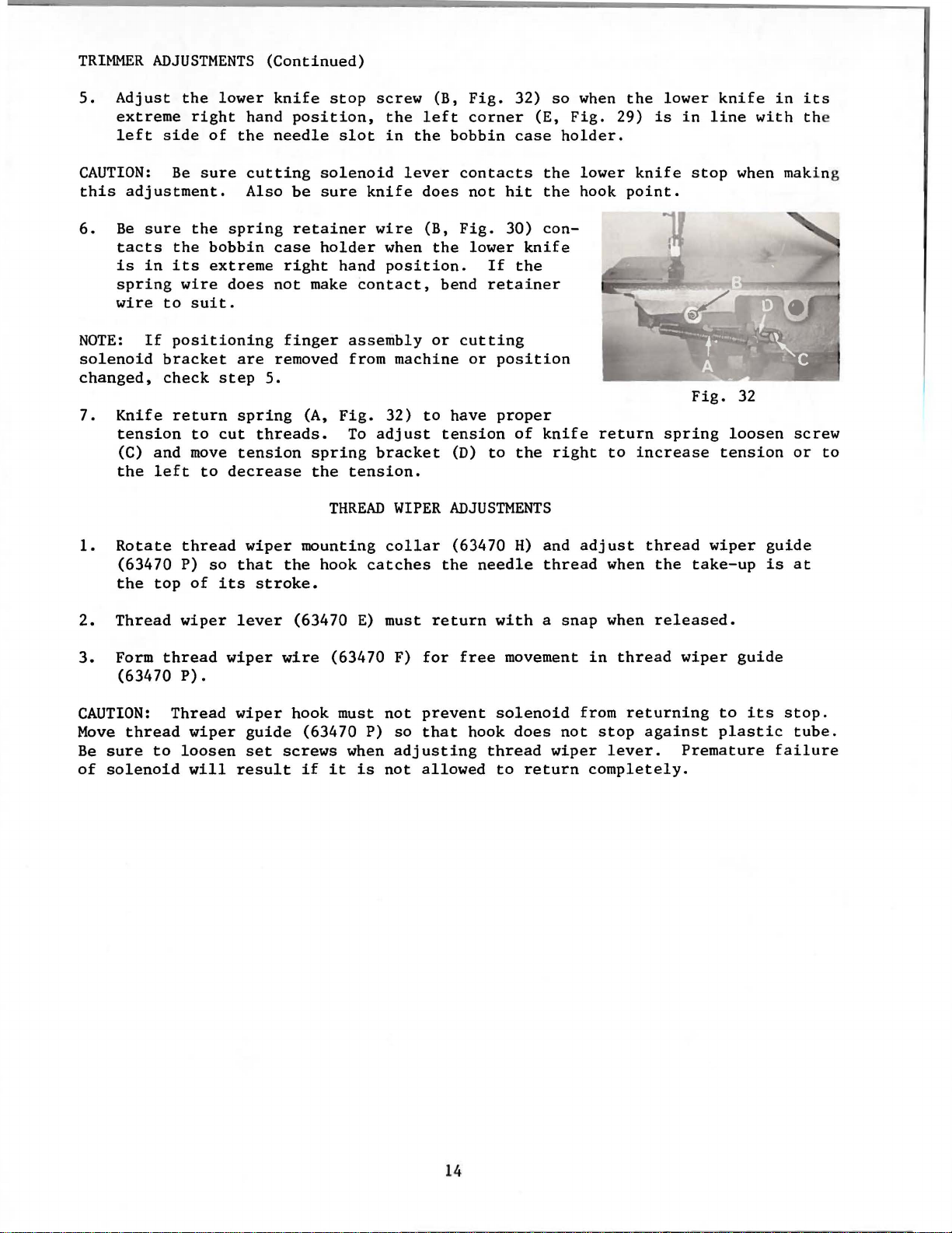
63400
63400
®
QUALITY
c
KC
MACHINES
CATALOG
No.
121
KC
.
CLASS
STREAMLINED
HIGH
HIGH
SPEED
LOCKSTITCH
THROW
UNION SPECIAL
63400
MACHINES
CORPORATION
CHICAGO
Page 2
C a t a 1 o g N
(
S u p p 1 e m e n t t o C a t a 1 o g N
o.
1 2 1 K C
I N S T R U C T I 0 N S
F 0 R
A D J U S T I N G A N D 0 P E R A T I N G
S T 0 F P A R T S
L I
C L A S S 6 3 4 0 0
S t r e a m 1 i n e d L o c k s t i t c h
S t y 1 e s
o.
1 2 1 M )
6 3 4 0 0 C 6 3 4 0 0 K C
F i r s t E d i t i o n
@ 1 9 7 7
b y
U n i o n S p e c i a 1 C o r p o r a t i o n
R 1 g h t s R e s e r v e d i n A 1 1 C o u n t r i e s
UNION SPECIAL CORPORATION
INDUSTRIAL
SEWING
CHICAGO
MACHINES
P r i n t e d i n
2
U.
S.
A.
April,
1977
Page 3
Each
into
special.
tain
letter
fixed
the
the
UNION
name
Standard
letter
"Z".
to
the
SPECIAL
plate
Style
"Z".
When
Standard
only
machine
on
the
numbers
Example:
minor
Style
IDENTIFICATION
is
identified
machine.
have
"Style
changes
number. Example:
Style
one
63400
are
OF
MACHINES
by a
numbers
or
more
C".
made
Style
are
letters
Special
in a standard
"Style
number
classified
suffixed,
Style
63400 CZ".
which
as
numbers
machine,
is
standard
but
never
contain
a "Z"
stamped
and
con-
the
is
suf-
Styles
which
"63400".
junction
not
clarity,
KC
number,
NOTE:
column.
those
catalog
structions
herein.
in
given
of
differs
This
used
parts.
Opposite
When
Adjusting
in
This
this
from
handwheel
of
machines
from
catalog
therewith.
on
Style
certain
description,
ordering
Catalog
are
that
catalog
It
can
class.
the
the
and
the
ones
pertain
also
Reference
operator's
is
toward
63400 B
No. 121 M
similar
the
style
is a supplement
Only
63400 B
illustration
and amount
repair
operating
that
applies
be
the
number,
APPLICATION
those
are
illustrated
parts
specifically
applied
position
are
page,
parts
instructions
for
Style
are
different
specifically
to
direction,
operator.
in
construction
in
to
Catalog
parts
required.
always
with
which
shown
parts
63400 B. The
to
discretion
while
that
OF
and
in
use
for
from
Styles
to
the
such
seated
are
grouped
it
contains
CATALOG
No. 121 M and
are
used
listed
phantom
are
identified
the
Styles
Style
63400 C and
Standard
as
part
only
63400 B
to
some
right,
at
the
to
under a class
no
letters.
should
on
Styles
at
the
back
help
number
63400 C and
Styles
left,
machine.
locate
by
detail
listed
instructions
or
are
KC.
of
Special
front,
be
used
63400 C
of
this
the
number,
in
KC
are
included
additional
machines
Styles
back,
Operating
number
Example:
in
con-
and
KC,
but
book.
63400 C and
part
the
second
similar
in
in-
as
listed
of
machines
etc.,
direction
For
to
this
are
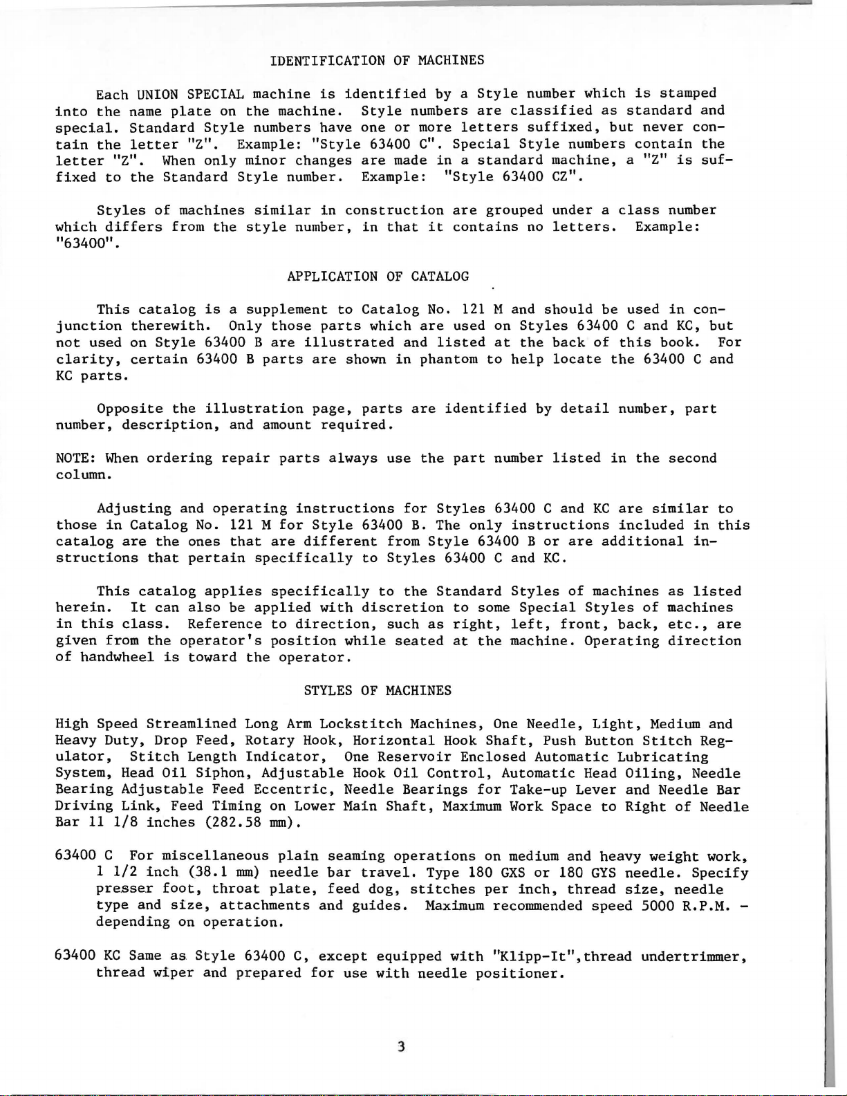
High Speed
Heavy
ulator,
System,
Bearing
Driving
Bar
63400 C
63400
Duty,
Stitch
Head
Adjustable
Link,
11
1/8
For
1
1/2
pre.sse
type
depending
KC
Same
thread
Streamlined
Drop
Feed,
Length
Oil
Siphon,
Feed Timing on Lower Main
inches
miscellaneous
inch
.r
and
foot,
size,
on
as
wiper
(38.1
Style
Long
Rotary
Indicator,
Adjustable
Feed
(282.58
throat
operation.
and
Eccentric,
mm)
attachments
63400 C,
prepared
Arm
mm).
plain
needle
plate,
STYLES
Lockstitch
Hook,
and
except
for
OF
Horizontal
One
Hook
Needle
seaming
bar
travel.
feed
dog,
guides.
use
with
MACHINES
Machines,
Reservoir
Oil
Control,
Bearings
Shaft,
operations
Type 180
stitches
Maximum
equipped
needle
One
Hook
Shaft,
Enclosed
for
Maximum
on
per
recommended
with
"Klipp-It",thread
positioner.
Needle,
Push
Automatic
Automatic
Take-up
Work
medium
GXS
or
inch,
Space
180
Light,
Button
Head
Lever
to
and
heavy
GYS
thread
speed
Medium and
Stitch
Lubricating
Oiling,
and
Needle
Right
needle.
size,
of
weight
needle
5000 R.P.M. -
undertrimmer,
Reg-
Needle
Bar
Needle
work,
Specify
Page 4
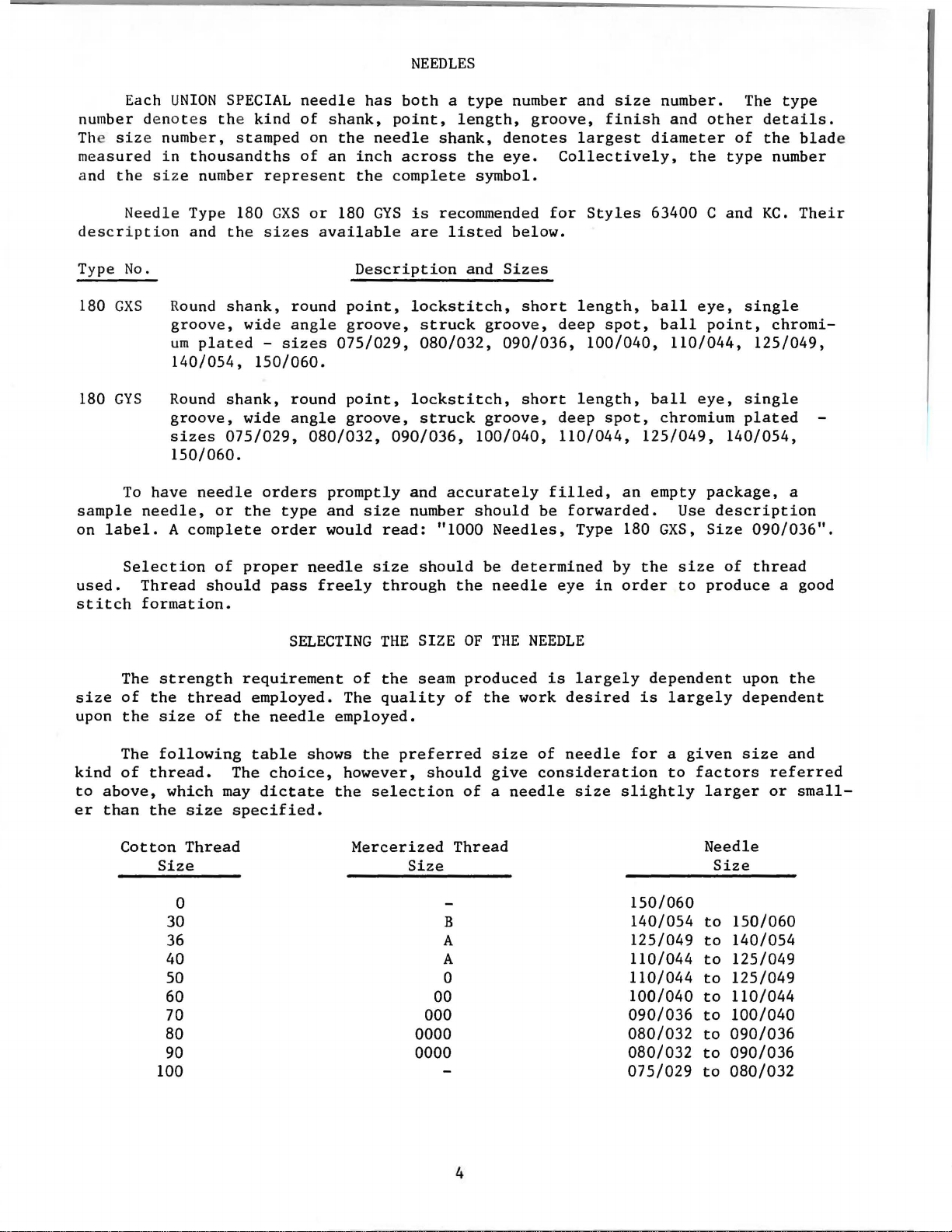
NEEDLES
Each U
number denot es the
The size number,
measured
the
and
Needle
description
Type
180
180
sample
on
No.
GXS
GYS
To
label.
NION
SPECIAL
in
thousandths
size
number
Type 180
and
the
Round
groove,
um
140/054, 150/060.
Round
groove,
sizes
150/060.
have
needle,
A
shank,
plated -sizes
shank,
075/029,
needle
or
complete
kind
stamped
represent
GXS
sizes
round
wide
wide
the
angle
round
angle
orders
type
order
needle
of
on
of
or
080/032,
has
both a type
shank,
the
an
180
available
075/029, 080/032,
promptly
and
would
point,
needle
inch
across
the
complete
GYS
Description
point,
groove,
point,
groove,
090/036,
size
read:
length,
shank,
the
symbol.
is
recommended
are
listed
and
lockstitch,
struck
lockstitch,
struck
100/040,
and
accurately
number
should
"1000
number and
groove,
denotes
eye.
below.
Sizes
short
groove,
090/036,
short
groove,
be
Needles,
size
finish
largest
Collectively,
for
Styles
length,
deep
100/040, 110/044,
length,
deep
110/044,
filled,
forwarded.
Type 180
diameter
63400 C and
ball
spot,
ball
spot,
125/049,
an
empty
number. The
and
other
of
the
type
eye,
ball
eye,
chromium
Use
GXS,
single
point,
125/049,
single
plated
140/054,
package,
description
Size
090/036".
type
details.
the
blade
number
KC.
Their
chromi-
a
used.
stitch
size
upon
kind
to
above,
er
than
Selection
Thread
formation.
The
strength
of
the
the
size
The
following
of
thread.
which
the
Cotton
Size
30 B
36 A
40
should
thread
of
size
Thread
0
of
proper
pass
requirement
employed.
the
needle
table
The
choice,
may
dictate
specified.
needle
freely
SELECTING
of
The
employed.
shows
however,
the
Mercerized
so
60 00
70 000
80
90 0000
100
size
through
THE
the
seam
quality
the
preferred
selection
Size
0000
should
the
SIZE
OF
produced
of
should
of a needle
Thread
A
0
be
determined
needle
THE
NEEDLE
the
work
size
give
by
eye
in
order
is
largely
desired
of
needle
consideration
size
for a given
slightly
150/060
140/054
125/049
110/044
110/044
100/040
090/036
080/032
080/032
075/029
the
size
to
dependent
is
largely
to
factors
to
to
to
to
to
to
of
thread
produce
upon
dependent
size
larger
Needle
Size
to
150/060
to
140/054
to
125/049
125/049
110/044
100/040
090/036
090/036
080/032
a good
the
and
referred
or
small-
4
Page 5
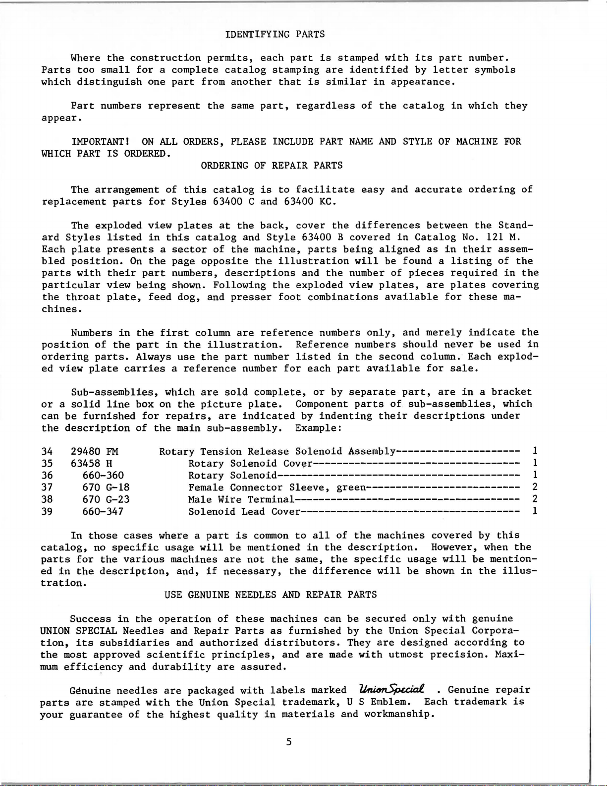
IDENTIFYING
PARTS
Where
Parts
which
too
distinguish
Part
appear.
IMPORTANT!
WHICH
PART
The
arrangement
replacement
The
ard
Styles
Each
plate
bled
position.
parts
with
particular
the
throat
chines.
Numbers
position
of
ordering
ed
view
plate
the
construction
small
numbers
IS
ORDERED.
parts
exploded
listed
presents
On
their
view
plate,
in
the
parts.
carries
permits,
for a complete
one
part
from
represent
ON
ALL
the
ORDERS,
ORDERING
of
this
for
Styles
view
part
being
the
part
Always
in
a
the
feed
first
this
in
plates
catalog
sector
page
opposite
numbers,
shown.
dog,
and
column
the
illustration.
use
the
a
reference
each
part
catalog
another
same
PLEASE
catalog
stamping
part,
INCLUDE
OF
REPAIR
is
that
is
regardless
to
facilitate
63400 C and 63400
at
the
and
of
the
machine,
the
descriptions
Following
presser
are
back,
reference
cover
Style
63400 B
illustration
and
the
exploded
foot
parts
combinations
Reference
part
number
number
for
listed
each
is
stamped
are
similar
PART
PARTS
KC.
the
the
numbers
in
part
identified
in
of
the
NAME
AND
easy
differences
covered
being
aligned
will
number
view
plates,
only,
numbers
the
second
available
with
its
by
part
letter
appearance.
catalog
STYLE
and
OF
accurate
between
in
Catalog
as
be
found a listing
of
pieces
are
available
and
merely
should
column. Each
for
number.
symbols
in
which
MACHINE
ordering
the
No. 121
in
their
required
plates
for
these
indicate
never
sale.
they
FOR
Stand-
assemof
in
covering
ma-
be
used
explod-
of
M.
the
the
the
in
Sub-assemblies,
or a solid
can
be
furnished
the
description
29480
34
35
63458 H
36
37
38
39
660-360
670 G-18
670 G-23
660-347
In
catalog,
parts
ed
in
for
the
tration.
Success
UNION
tion,
the
mum
SPECIAL
its
most
effici~ncy
line
FM
those
no
cases
specific
the
various
description,
in
Needles
subsidiaries
approved
and
which
box on
for
repairs,
of
the
Rotary
where a
usage
USE
the
operation
scientific
durability
are
the
picture
main
sub-assembly.
Tension
Rotary
Rotary
Female
Male Wire
Solenoid
part
will
machines
and,
if
GENUINE
and
Repair
and
authorized
principles,
sold
are
complete,
plate.
indicated
or
by
Component
by
indenting
separate
parts
their
part,
of
sub-assemblies,
descriptions
Example:
Release
Solenoid
Solenoid
Cov~r-----------------------------------
Assembly---------------------
Solenoid----------------------------------------Connector
Sleeve,
green--------------------------
Terminal--------------------------------------
Lead
is
be
are
necessary,
NEEDLES
of
these
Parts
are
assured.
Cover-------------------------------------
common
mentioned
not
distributors.
to
all
in
the
same,
the
difference
AND
REPAIR
machines
as
furnished
and
are
of
the
the
description.
the
specific
PARTS
can
be
by
They
made
machines
will
secured
the
are
with
Union
designed
utmost
usage
be
only
are
in a bracket
covered
by
However, when
will
be
shown
Special
with
in
the
genuine
Corpora-
according
precision.
which
under
1
1
1
2
2
1
this
the
mention-
illus-
to
Maxi-
parts
your
Genuine
are
guarantee
needles
stamped
of
with
the
are
packaged
the
highest
Union
quality
with
Special
in
labels
trademark,
materials
5
marked
U S Em
and workmanship.
~
blem.
. Genuine
Each
trademark
repair
is
Page 6
TERMS
!'rices
.tru
forwarded
wisu
directed.
CAUTION!
handwheel.
Before
carefully
box,
the
A
bag
attaching
cellaneous
The
bracket,
clamp
and
Insert
the
upper
are
f.o.b.
A
~1en
Using
leaving
packed.
following
of
assembly
screw,
attachment
bag
of
one
synchronizer
three
hinge
frame
strictly
shipping
charge
unpacking,
both
factory,
After
steps
PREPARATION
one
extra
to
assembly
clamps
studs
eyelet
net
is
hands
the
should
parts,
the
parts
lead
for
in
to
top
cash
point.
made
DO
on bed
each
machine
OF
consisting
bobbin,
bed
for
wire
tension
holes
of
and
subject
Parcel
to
cover
INSTALLING
NOT
lift
casting,
UNION
and
be
followed:
MACHINE
two
hinge
plate,
Style
clamp,
release
provided
arm (A,
to
Post
the
postage
machine
lift
SPECIAL
accessories
FOR
INSTALLATION
of
one
studs,
are
packed
fi3400
one
KC
screw
solenoid
for
them
Fig.
2A
change
shipments
and
out
gently.
machine
have
frame
thread
and
with
also
for
lead
in
rear
or
2B).
without
are
insurance.
of
box
by
is
sewed
been
eyelet,
two
screws
each
machine.
includes
synchronizer
wire.
of
cloth
notice.All
insured
placing
off,
unless
one
inspected
removed from
one
eyelet
for
holding
one
synchronizer
lead
plate.
shipments
other-
hand
on
and
packing
mis-
wire
Assemble
STANDARD
Included
one
bobbin
clamp
and
are
TABLE
spring,
screw,
essential
TOPS
Lockstitch
the
bed
plate
ACCESSORIES
also
with
winder
four
one
isolator
when
assembly,
knee
setting
machines
is
FLUSH
each
lifter
pads
are
with
machine
the
assembly
and
up
the
installed
the
is a box
machine
clips,
machine.
top
of
mounting
and
its
and
in
table
the
machine
of
STANDARD
frame,
rubber
one
machine
tops,
one
pad,
rest
prepared
mounting
ACCESSORIES-containing
oil
bed
positioning
pin.
with
drain
jar
These
cut-out,
and
spring
parts
so
its
frame.
that
6
Page 7
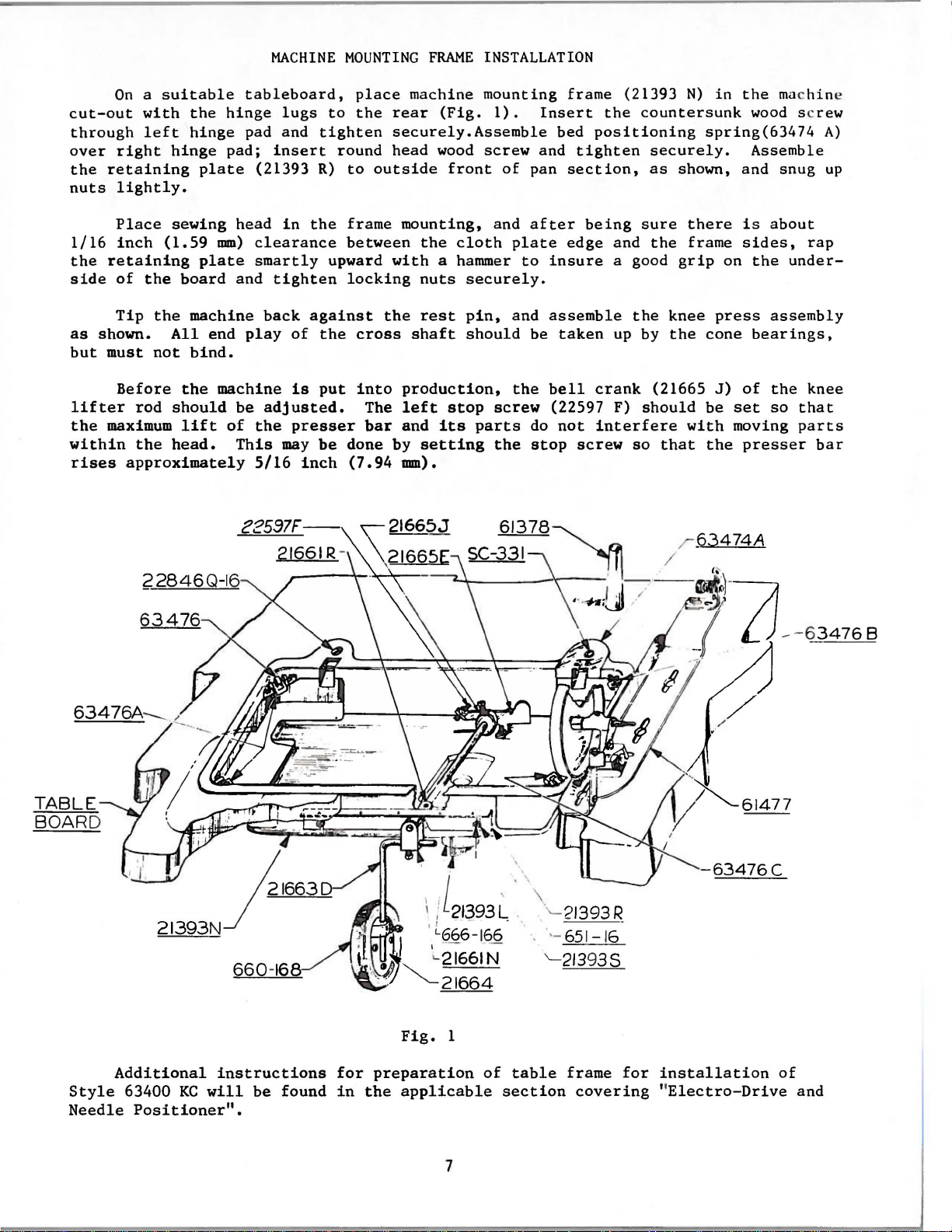
MACHINE
MOUNTING
FRAME
INSTALLATION
On a suitable
cut-out
through
over
right
the
retaining
nuts
side
as
but
within
1/16
the
shown.
lifter
the
rises
lightly.
Place
inch
retaining
of
Tip
must
Before
maximum
approximately
with
left
the
the
not
rod
the
the
hinge
hinge
plate
sewing
(1.59
plate
board
machine
All
bind.
the
should
lift
head.
tableboard,
hinge
pad and
pad;
(21393
head
mm)
clearance
smartly
and
end
play
machine
be
of
the
This
5/16
lugs
tighten
insert
R)
in
the
tighten
back
against
of
the
is
put
adjusted.
presser
may
be
inch
place
to
the
round
to
outside
frame
between
upward
locking
cross
into
The
bar
done
(7.94
machine
rear
securely.Assemble
head
mounting,
the
with
nuts
the
rest
shaft
production,
left
and
by
setting
mm).
mounting
(Fig.
wood
a hammer
stop
its
1).
screw
front
and
cloth
securely.
pin,
should
screw
parts
the
of
Insert
and
pan
after
plate
to
and
be
the
do
stop
frame (21393
the
bed
positioning
tighten
section,
being
edge
and
insure
assemble
taken
bell
(22597 F)
not
a good
up by
crank
interfere
screw
N)
countersunk
spring(63474
securely.
as
shown, and
sure
the
so
the
grip
knee
the
(21665
should
that
there
frame
cone
be
with
the
in
the mac
is
sides,
on
press
J)
of
set
moving
presser
hin
wood
Assemble
screw
snug
about
rap
the
under-
assembly
bearings,
the
knee
so
that
parts
e
A)
up
bar
TABLE
BOARD
22846Q-16
63476
·.'-21393R
. ·-65
'-
213935
1-1
6
-
63476C
Fig.
1
Additional
Style
Needle
63400
Positioner".
instructions
KC
will
be
found
for
preparation
in
the
applicable
7
of
section
table
frame
covering "Electro-Drive
for
installation
of
and
Page 8
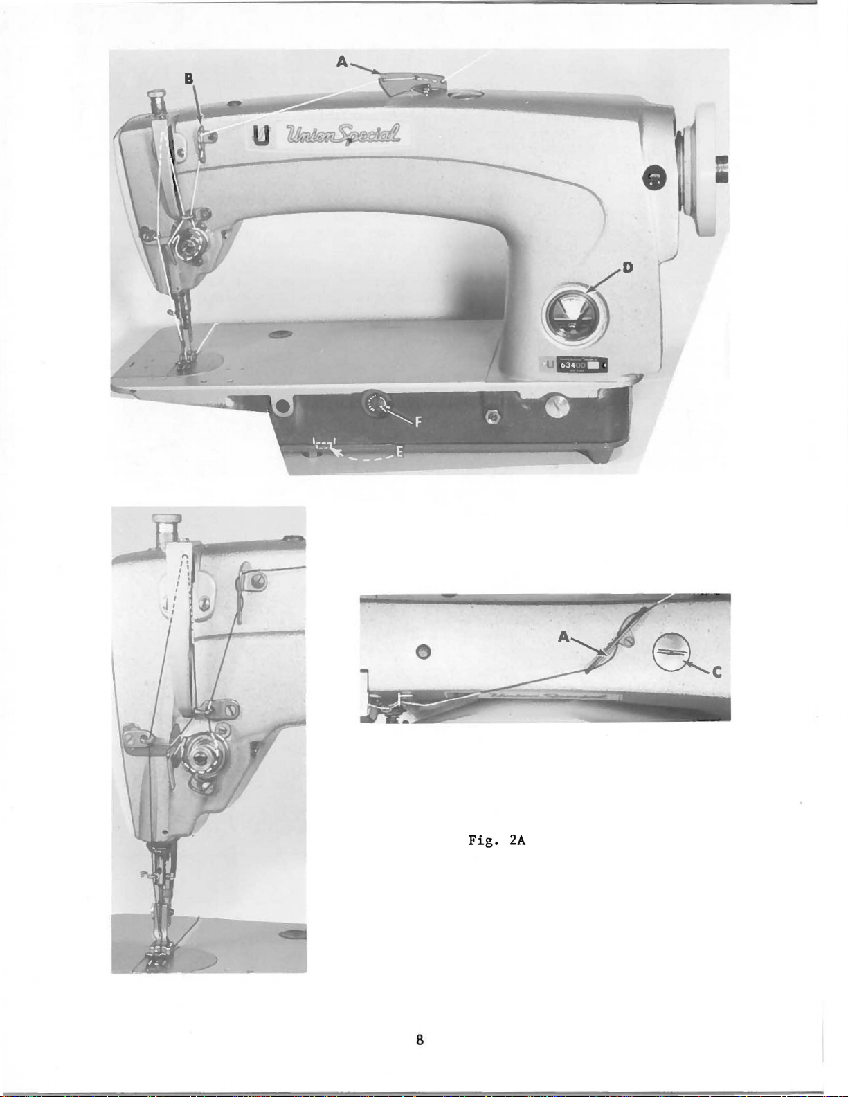
Fig.
8
2A
Page 9
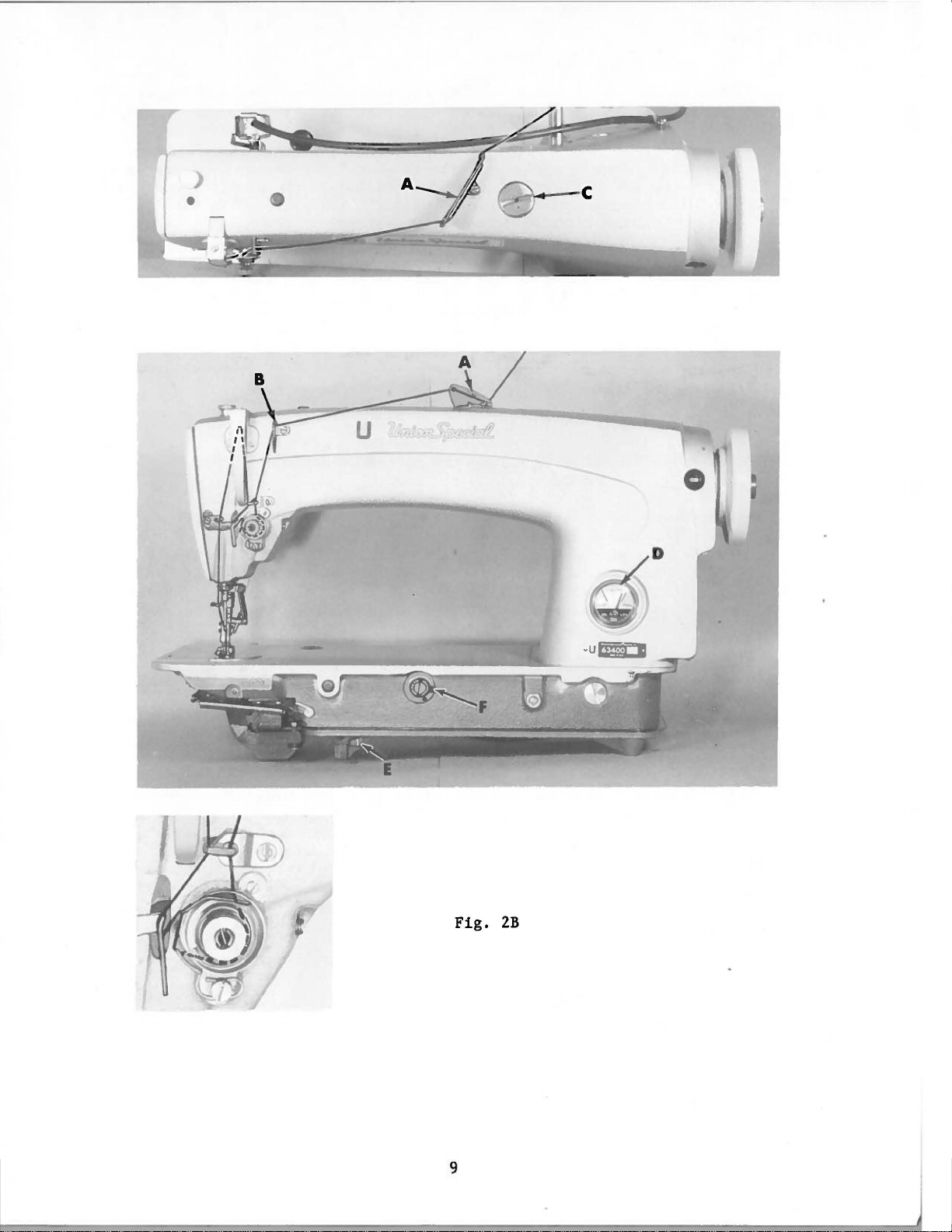
B
Fig.
2B
Page 10

The
located
when
in
allow
pulley
the
belt
scribed
121
M.
bobbin
directly
operation.
the
mechanism
of
the
to
under
winde
winder,
wind
"Winding
in
the
BOBBI
r sho
uld
be
secured
f ront
The b
to
of
t he sewi ng machi ne
ase
of the wi nd e r has two
be moved closer to
when
bobbin.
the
in
operation,
Regulation
Bobbin",
N WI NDER
to Lhe t
should
and
under
BELTS
able
belt
elongated
or
farther
exert
operation
OPERATOR'S
top
so
that
and
will
away from
only
of
INSTRUCTIONS
bear
attaching
enough
the
bobbin
belt
its
pulley
against
holes,
as
needed.
pressure
winder
in
Catalog
will
the
belt
which
against
is
de-
No.
be
The
These
Thread
tively.
threaded
reservoir
gauge
line,
when
"LOW".
90
Union
2B).
the
and
Threading
CAUTION!
Fill
(D).
located
needle
Use a
to
125
Special
Oil
The
dial
in a clockwise
machines
machine
from
left
must
main
Oil
to
is
stainless
seconds
specification
may
be
quantity
in
the
are
Styles
at
the
to
Oil
has
be
filled
reservoir
is
at
the
right
to
the
at
100°
drained
of
oil
direction
direction
equipped
63400 C
check
right.
been
maximum
black
drained
before
at
plug
of
line,
water-white
Fahrenheit
No.
from
supplied
of
to
THREADING
and
spring
OILING
starting
screw
safe
operating
"OPERATE"
located
175.
main
decreases
the
reservoir
to
arrow
use
either
KC
has
from
straight
the
to
(C,
zone,
in
the
the
hook
(counterclockwise)
the
as
indicated
been
main
operate.
Fig.
level
to
the
mineral
main
by
oil
Ill
enlarged
marked
removing
is
flow.
"Vee"
reservoir
2A
or
2B)
when
"FULL".
left
of
oil
reservoir.
controlled
or
round
in
Figs.
for
clarity.
before
and
check
the
needle
Oil
"OPERATE"
of a Saybolt
This
plug
screw
by
dial
increases
belts.
2A
and
shipment
is
should
zone,
is
(E,
2B
respec-
Needle
oil
level
to
the
be
marked
viscosity
equivalent
Fig.
(F).
the
Turning
oil
is
and
at
black
added
of
2A
or
flow
the
to
It
is
a
long
recommended
period,
be
Fig.
that
lubricated
12A
a new
by
machine,
removing
parts.
further
chine
oil
can
or
the
slowly
to
then
10
one
head
After
hand
the
be
that
cover
oiling,
oiling
for
various
expected
has
and
will
several
parts.
without
been
out
oiling
replace
be
minutes
Full
of
service
all
the
head
required.
to
speed
damage.
moving
cover
as
Run
distribute
operation
for
no
ma-
Page 11
The
63400 B
instructions
headings
covered
adjusting
that
will
indicate
instructions
in
Catalog
are
INSTRUCTIONS
No.
different
the
page
for
121
from
it
Styles
H,
the
can
FOR
HECHANICS
63400 C and
with
following
ones
be found
covered
in
that
KC
are
exceptions
in
Catalog
catalog.
the
same
and
No.
as
for
additions.
121
M,
Style
The
the
The
(11.11
This
dimension
by
tipping
and
relocating
stop
screw
be
obtainable.
NOTE:
this
adjustment,
as
possible
presser
mm)
If
above
the
to
the
without
bar
the
should
machine
the
stop
the
right
Tighten
1/32
inch
the
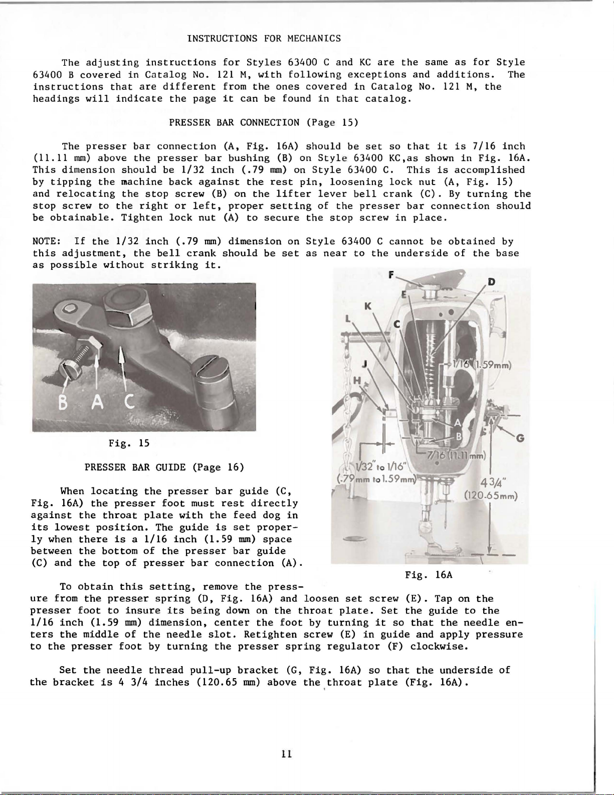
PRESSER
connection
presser
be
1/32
back
screw
or
left,
lock
(.79
bell
striking
crank
BAR
(A,
bar
inch
against
(B) on
proper
nut
(A)
mm)
should
it.
CONNECTION
Fig.
bushing
(.79
the
to
dimension
the
secure
be
16A)
(B) on
mm)
rest
lifter
setting
on
set
(Pag
should
on
pin,
the
Style
as
e 15)
Styl
Style
loosening
lever
of
stop
near
be
set
so
that
e 63400 KC,as shown
63400 C.
bell
the
presser
screw
63400 C
to
the
This
lock
crank
bar
in
place.
cannot
underside
nut
(C).
connection
be
it
is
7/16
in
Fig.
is
accomplished
(A,
Fig.
By
turning
obtained
of
the
inch
16A.
15)
the
should
by
base
When
Fig.
against
its
ly
between
ure
presser
1/16
ters
to
the
(C)
16A)
lowest
when
and
To
from
inch
the
the
Set
bracket
PRESSER
locating
the
the
position.
there
the
the
obtain
the
foot
(1.59
middle
presser
the
is 4 3/4
Fig.
BAR
presser
throat
is a 1/16
bottom
top
of
this
presser
to
insure
mm)
of
foot
needle
15
GUIDE
the
presser
foot
plate
The
inch
of
the
presser
setting,
spring
its
dimension,
the
needle
by
turning
thread
inches
(Page
must
with
guide
presser
bar
(D,
being
pull-up
(120.65
16)
bar
guide
rest
the
feed
is
set
(1.59
remove
slot.
mm)
bar
connection
Fig.
down on
center
the
presser
bracket
(C,
directly
dog
proper-
space
guide
(A).
the
press-
16A)
Retighten
mm)
the
above
and
the
foot
in
loosen
throat
by
screw
spring
(G,
Fig.
the,throat
set
plate.
turning
(E)
in
regulator
16A)
screw
Set
it
guide
(F)
so
that
plate
Fig.
(E).
the
so
that
and
clockwise.
the
(Fig.
16A
Tap on
guide
the
apply
underside
16A).
the
to
the
needle
pressure
G
en-
of
11
Page 12
1.
2.
3.
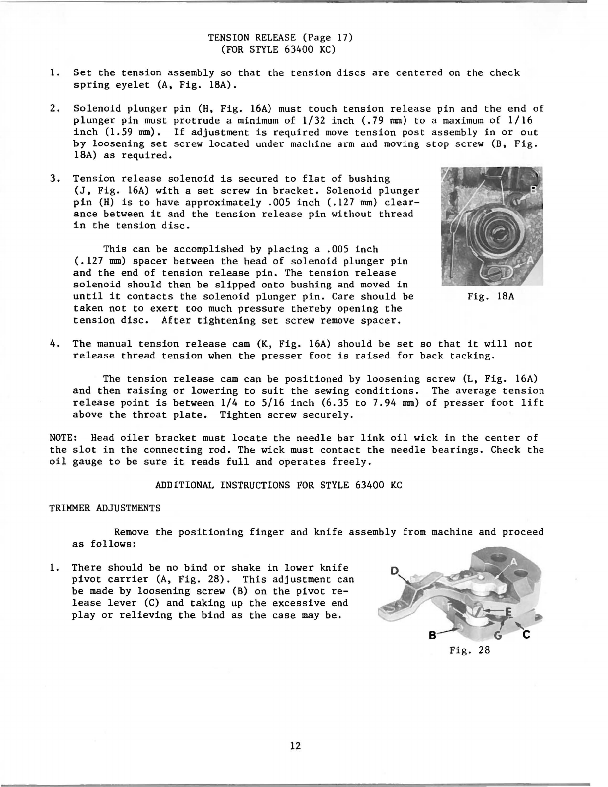
Set
the
spring
Solenoid
plunger
inch
by
18A)
Tension
(J,
pin
ance
in
(.127
and
solenoid
until
taken
tension
(1.59
loosening
as
Fig.
(H)
between
the
This
mm)
the
it
not
tension
eyelet
plunger
pin
must
mm).
required.
release
16A)
is
to
tension
can
spacer
end
of
should
contacts
to
disc.
assembly
(A,
Fig.
pin
protrude
If
adjustment
set
screw
solenoid
with a set
have
approximately
it
and
the
disc.
be
accomplished
between
tension
then
the
exert
too
After
TENSION
(FOR
so
that
18A).
(H,
Fig.
a minimum
located
is
secured
screw
tension
the
release
be
slipped
solenoid
much
pressure
tightening
RELEASE
STYLE
the
16A)
is
under
in
.005
release
by
placing
head
pin.
onto
plunger
set
(Page
63400
tension
must
of
1/32
required
machine
to
flat
bracket.
inch
of
solenoid
The
bushing
pin.
thereby
screw
17)
KC)
discs
touch
inch
move
arm
of
Solenoid
(.127
pin
witl1out
a
.005
tension
and moved
Care
opening
remove
are
tension
(.79
tension
and
bushing
mm)
inch
plunger
release
should
spacer.
centered
release
mm)
post
moving
plunger
clear-
thread
pin
in
be
the
on
the
pin
and
to a maximum
assembly
stop
screw
Fig.
check
the
of
in
(B,
18A
end
1/16
or
of
out
Fig.
4.
The
release
and
release
above
NOTE:
the
slot
oil
gauge
TRIMMER
as
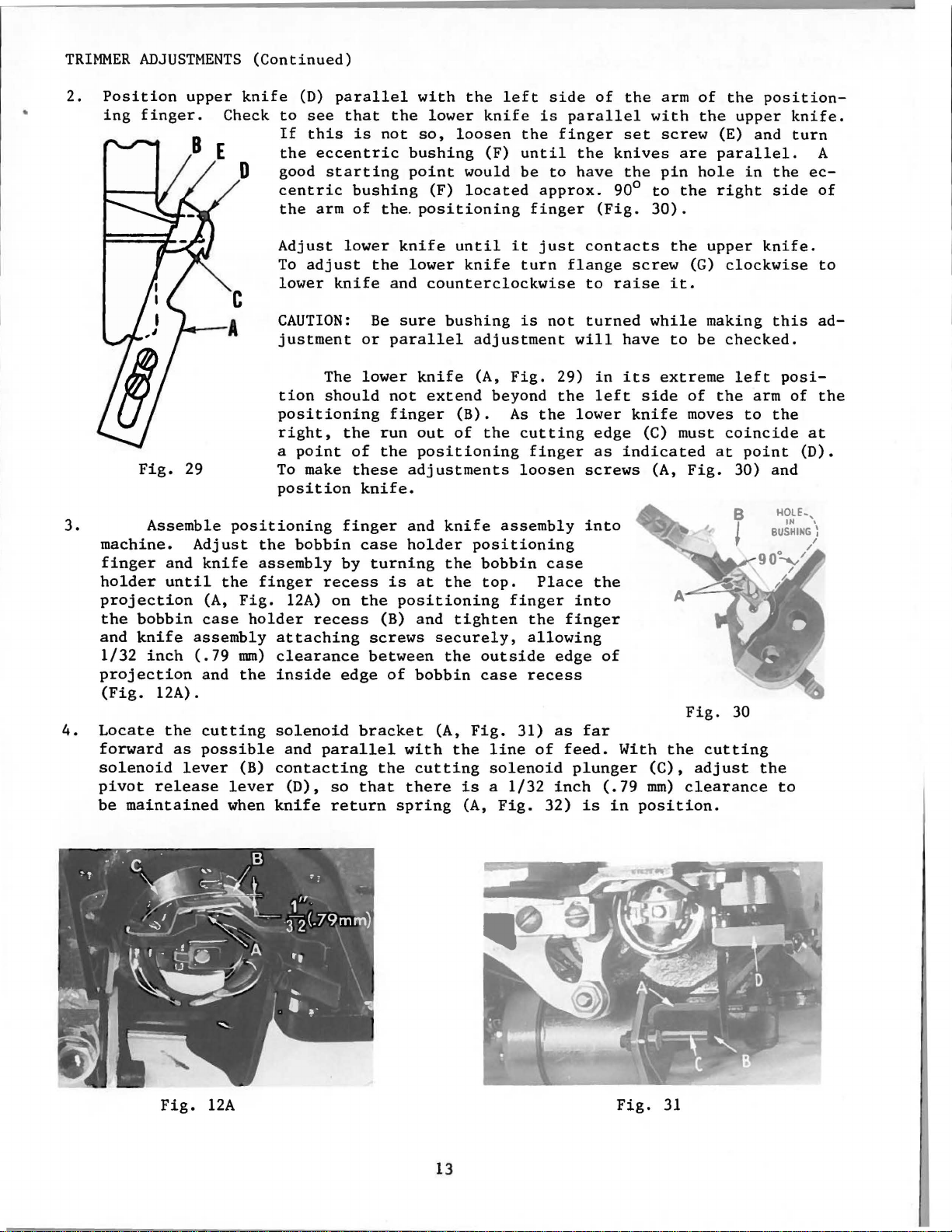
1.
There
pivot
be
made
lease
play
manual
The
then
Head
in
ADJUSTMENTS
follows:
should
carrier
lever
or
thread
tension
raising
point
the
throat
oiler
the
to
be
Remove
by
relieving
tension
connecting
sure
be
loosening
(C)
release
tension
release
or
is
between
plate.
bracket
it
ADDITIONAL
the
no
(A,
Fig.
and
the
when
lowering
must
rod.
reads
positioning
bind
28).
screw
taking
bind
cam (K,
the
presser
cam
can
be
to
suit
1/4
to
5/16
Tighten
locate
The
full
INSTRUCTIONS
or
shake
(B)
up
as
wick
and
finger
This
on
the
the
screw
in
adjustment
the
excessive
case
Fig.
foot
positioned
the
inch
securely.
the
needle
must
operates
FOR
and
lower
pivot
may
16A)
sewing
(6.35
contact
freely.
STYLE
knife
knife
reend
be.
should
is
raised
by
loosening
conditions.
to
bar
link
the
63400
assembly
can
be
7.94
set
for
mm)
oil
wick
needle
KC
from
so
that
back
screw
The
of
presser
in
bearings.
machine
it
tacking.
(L,
average
the
and
will
Fig.
tension
foot
center
Check
proceed
not
16A)
lift
of
the
12
Fig.
28
Page 13
TRIMMER
2.
Position
ing
ADJUSTMENTS
upper
finger.
knife
Check
0 good
(Continued)
(D)
parallel
to
see
If
this
the
eccentric
starting
centric
the
arm
with
that
the
is
not
so,
bushing
point
bushing
of
the. positioning
lower
loosen
would
(F)
the
left
knife
(F)
located
side
is
the
until
be
to
approx.
finger
of
parallel
finger
the
have
(Fig.
the
with
set
knives
the
90°
to
30).
arm
screw
are
pin
the
of
the
the
(E) and
parallel.
hole
right
position-
upper
in
knife.
turn
the
side
A
ec-
of
3.
4.
Fig.
Assemble
machine.
finger
holder
projection
the
and
1/32
projection
(Fig.
Locate
forward
solenoid
pivot
be
and
until
bobbin
knife
inch
12A).
the
release
maintained
29
Adjust
knife
(A,
case
assembly
(.79
and
cutting
as
possible
lever
Adjust
To
lower
CAUTION:
justment
tion
positioning
right,
a
To
position
positioning
the
assembly
the
finger
Fig.
mm)
the
(B)
lever
when
12A)
holder
attaching
clearance
inside
solenoid
and
contacting
(D),
knife
adjust
knife
The
should
point
make
bobbin
recess
on
recess
edge
parallel
so
return
lower
the
Be
or
lower
the
of
these
knife.
finger
case
by
turning
the
screws
between
bracket
the
that
knife
lower
and
sure
parallel
not
finger
run
the
adjustments
and
holder
is
positioning
(B) and
of
with
there
spring
until
counterclockwise
bushing
knife
extend
(B).
out
of
positioning
knife
the
at
the
tighten
securely,
the
bobbin
(A,
the
cutting
it
knife
adjustment
positioning
Fig.
is a 1/32
(A,
(A,
Fig.
beyond
As
the
cutting
loosen
assembly
bobbin
top.
finger
outside
case
31)
line
solenoid
Fig.
turn
is
finger
the
allowing
recess
just
flange
not
29)
the
the
case
Place
finger
edge
as
of
feed.
inch
32)
contacts
to
raise
turned
will
lower
into
plunger
have
in
its
left
edge
as
indicated
screws
into
the
of
far
With
(.79
is
in
the
screw
it.
while
to
extreme
side
knife
(C) must
(A,
the
(C),
mm)
position.
upper
(G)
clockwise
making
be
checked.
left
of
the
moves
Fig.
Fig.
adjust
clearance
to
coincide
at
point
30) and
30
cutting
knife.
this
arm
the
the
to
posi-
of
at
(D).
to
ad-
the
Fig.
12A
13
Fig.
31
Page 14
TRIMMER
5.
Adjust
extreme
left
ADJUSTMENTS
the
lower
right
side
of
hand
the
(Continued)
knife
needle
stop
position,
slot
screw
the
in
left
the
(B,
bobbin
Fig.
corner
32)
(E,
case
so
when
Fig.
holder.
the
29)
lower
is
in
knife
line
in
its
with the
CAUTION:
this
adjustment.
6.
Be
sure
tacts
is
in
spring
wire
NOTE:
solenoid
changed,
7.
1.
2.
If
Knife
tension
(C)
the
Rotate
(63470 P)
the
Thread
Be
sure
the
the
bobbin
its
extreme
wire
to
suit.
positioning
bracket
check
return
to
and
move
left
top
to
thread
so
of
wiper
cutting
Also
spring
does
are
step
cut
its
5.
spring
threads.
tension
decrease
wiper
that
stroke.
lever
solenoid
be
sure
retainer
case
holder
right
not
make
finger
removed from
(A,
spring
the
mounting
the
hook
(63470
knife
wire
hand
contact,
assembly
Fig.
To
adjust
bracket
tension.
THREAD
catches
E)
lever
does
(B,
when
position.
32)
collar
must
the
bend
or
machine
to
tension
WIPER
the
return
contacts
not
Fig.
lower
If
retainer
cutting
or
position
have
proper
(D)
to
ADJUSTMENTS
(63470
needle
with a snap
hit
30)
the
of
the
H)
the
the
con-
knife
knife
right
and
thread
lower
hook
return
to
adjust
when
when
knife
point.
spring
increase
thread
the
released.
stop
when making
Fig.
32
loosen
tension
wiper
take-up
screw
or
guide
is
at
to
3.
Form
(63470
CAUTION:
Move
Be
of
thread
sure
solenoid
thread
P).
Thread
to
loosen
wiper
will
wiper
wiper
guide
set
result
wire
screws
(63470 F)
hook must
(63470 P)
when
if
it
is
not
not
for
prevent
so
that
adjusting
allowed
free
hook
movement
solenoid
does
thread
to
return
in
from
not
wiper
completely.
thread
returning
stop
lever.
wiper
against
Premature
guide
to
its
plastic
stop.
tube.
failure
14
Page 15

ADJUSTING
AMCO
INSTRUCTIONS
FOR
ELECTRO
DRIVE
and
15
NEEDLE
POSITIONER
Page 16

......
0\
TU~G.
FR
RE.LU~
OM
TENSION
SOLENOID
-
-
CLAMP
- SY
NCHRONIZER
·~34~5D
SRAC..KET
J87J
*
S
CRE
.W
(CON
'SEE
I<I
ECTOI?)
a:rA/L
{:;
-.
=
,J
----:r.
,
-
..,.
,.
::::,
~,_,_,
*sc-
SC
2.92
REW
SCREWS
( DIA.
(BRACKET
S
EE
DETAIL
)-'
DRILL
R
ONI
ZE.R
NUTS TO
SECUR£
BOX
**
TRIMM
E!t
CiRCUIT I
WI
TH
RELAYS
FROM 8 0)( N/0 tWS
f¥11/'i
T£0
T,.
CIRCUIT
WI
IHM
eaAR
TH SCKE"S.
D /l.SECuRI!.
3~Z
ATIONS
OF
'FI.
UNDERTR
* IN DICA
DIM
NOT EQ
**
IMMER ELECTRONI
FOR 63<10
TES PART
ENSIONS
UIPPED WITH
INDIC
ATES 'PM T INCLUDED IN
Tf/E
800XT 362
NEE S
0
&.
6.3900 SEit
SHO
WN
Z<?J4tJDTV
BUT
IS
WI
TCH
1
..
ij: DIA.
C. EQUI
iES
INCLUDE
STANCARD
1=\
MACHINE
D IN
FOR
DRILLED
·KNE
E S
WI
\lr::\IL
~BL.
IM JN
E.
AT£S
E:L
P MENT
PAC
H
OLES
294eO
TCH;
(
EXTRA
TR
K IN
HOL
E:A
.
WHI
DLIN
PART
<;.
BOX
ES
AI<
E FOR INSTALL
HP
CH
IS NOT PART
SEND&.
E :JWITC.
BQ.\RD
NOTE
: REMOVE POWER PAC/<
NO
800XT-
CHARG£ ).
I-I
.
GRT
1':::::!
UNION
C
HIOI40,~
Fi
SPE
g . lA
CIAL
CO~f'O~ATION
ACII
S
?.Oi>/
0 U.
S.A
(.()IN
ECT
ED
1
1-JSIDE.
OF
SWITCH
EOX
.
AI?INT£0
U.
IN
S.A.
Page 17

PREPARATION
OF
TABLE
FRAME
FOR
INSTALLATION
Using
1.
Attach
2.
Attach
3.
Slide
4.
Attach
5.
Wire
leg
6.
Attach
ed.
7.
Attach
8.
Secure
using
drive,
9.
Connect
lease
(376
Fig.
the
A)
screws.
synchronizer
clamp
clamp
leads
of
table
power
Drill
electro
electrical
clamps
clutch
leads
solenoid
green.
10.
Assemble
SYNCHRONIZER
(a)
Rotate
handwheel
deflector
needle
on
1A
as a guide,
synchronizer
The
to
(660-356)
to
synchronizer
with
striped
frame.
pack
holes
in
to
table
drive
cable
and
screws
arm
switch
from power
(green
relays
as
shown
ADJUSTMENT
in
plate
the
up
(C,
stroke
proceed
bracket
upper
screw
adaptor
over
synchronizer
ends
left
rear
leg
to
underside
and
provided.
and
pack
leads).
in
operating
Fig.
12A)
of
(63495
also
of
bracket
to
switch
leg
if
required.
leads
treadline
to
cutting
Be
Fig.
direction
on
the
needle
as
follows:
D)
to
hold
handwheel
lead
using
box
of
table
of
table
to
underside
Connect
or
solenoid
sure
to
38.
until
the
rotating
bar.
to
the
clamp
assembly
wire.
(J87
and
attach
frame
board.
of
cable
knee
switch.
connect
the
hook
back
(660-352)
using
J)
screw.
using
tableboard
to
power
(white
white
needle
assembly
of
machine,
switch
nuts
pack,
leads)
to
clearance
in
the
box
and
and
white
is
using
position.
two
set
to
right
bolts
to
table
auxiliary
and
tension
and
green
cut
in
line
two
screws.
front
provid-
frame
re-
to
in
the
with
the
Then
its
loosen
brush
up and
Fig.
down
screw
is
in
positions
33
at
the
end
middle
of
(b)
(C)
(d)
of
synchronizer
of
the
the
needle
At
this
(A,
Fig.
of
the
brush
position
scribed
in
synchronizer
Down
hook
needle
time".
to
this
position
point
by
If
synchronizer
in
operating
middle
The
thread
(3.18
with
of
needle
take-up
mm)
power
rection
and
black
plastic
bar.
time
33)
needle
in
step
has
5/64
not,
point.
the
positioner
from
off
until
rotate
the
brass
should
holder
bar
(a),
and
should
passed
of
an
with
Then
and
rotate
direction
black
at
top
the
top
rotate
it
is
fourth
band.
contact
be
flush
(B).
To
and
deflector
then
loosen
move
as
be a point
the
center
inch
power
(1.
off,
loosen
third
until
plastic
should
of
its
of
its
handwheel
at
the
top
band from
Turn
on power and
of
with
make
required.
at
98
mm)
rotate
screw
band
its
brush
band.
position
stroke
up
stroke.
in
of
the
left
the
front
this
adjustment
plate
set
screws
which
line
of
"loop
handwheel
(D)
at
from
needle
or
operating
its
stroke.
left
check
as
end
left
is
1/8
(F)
band
edge
de-
(C)
the
the
taking
of
in
inch
If
not,
until
the
(E)
the
di-
17
Page 18

CLUTCH
(a)
Set
(b)
Adjust
nut
(c)
Close
there
needle
ARM
needle
washer
treadline
is
SWITCH
in
clutch
{B)
no
contact
positions
ADJUSTMENT
work.
arm
spring
is
to
be
approximately
switch
up.
and
between
Tighten
(A,
loosen
Fig.
it
and
nut
34)
so
1/2
clutch
the
(D)
to
that
lever
microswitch.
maintain
inch
treadle
(12.70
switch
will
mm)
adjusting
Then
setting.
return
from end
screw
tighten
to
stop
of
screw
stud}.
(C),
until
(wing
until
ADJUSTING
(a)
Depress
(b)
Adjust
3.18
(where
one
the
clutch
Tighten
CAUTION!
lever
running;
clutch
INSTALLATION
No. M6665)
(A,
Fig.
#3
on
inching
properly.
full
top
switch
is
When
socket
switch
CLUTCH
clutch
mm)
it
is
Clutch
one
engaged.
installing
be
35)
treadle
travel
says
turn.
on
right
engaged
lock
must
is
closed
click
OF
INCHING
sure
located
(B)
plug
unit
so
that
before
"Lock
Adjust
end
screw
not
must
inching
to
between
before
or
until
clutch
clutch
Motor")
screw
of
motor,
as
described
(E).
engage
or
auxiliary
be
heard
SWITCH
remove
connecting
it
will
one
arm
is
just
located
when
before
switch,
jumper
pin
#2 and
not
click
has
engaged.
enough
near
until
above.
clutch
motor
(Amco
wire
pin
the
function
is
heard,
approximately
to
which
Loosen
unlock
indicates
1/16
lock
it,
to
screw
which
Fig.
switch
1/8
inch
(E,
Fig.
is
approximately
34
is
(1.59
34)
open.
to
Should
35)
must
PUSHBUTTON
edge
of
the
treadle
the
ables
with
trimmed
be
If
the
of
the
synchronizer
is
needle
the
operator
the
needle
the
"the
inching
replaced
FUNCTION
pushbutton,
table
heeled
will
threads.
board,
while
position
out
or
is
interrupted.
to
readjust
of
the
switch
the
needle
which
is
depressed,
the
pushbutton
up
without
work,
be
removed
positioning
is
mounted on
Therefore,
trimming.
or
realign
but
the
is
depressed,
the
without
18
at a later
unit
the
front
cutter
when
This
garment
having
date,
will
band
the
en-
not
the
jumper
position
Fig.
wire
up.
35
(A,
Fig.
Page 19

TREADLINE
To
adjust
36)
loosen
Adjust
adjustment
the
tain
the
less
tension
actuating
switch
ered.
is
on
bevel
is
rods
three
the
If
more
treadle,
accordingly
bushing
If
more
actuator
Care
provided
the
switch
on
accomplished
SWITCH
the
as
is
necessary
bushings
desired
or
the
travel
the
trim
should
to
should
the
micro-
ADJUSTMENT
the
length
two
Allen
required
inside
length.
less
pressure
spring
by moving
(C) up
(D)
actuate
by
or
is
cycle,
and
be
taken
the
not
switch
adjustment
of
the
set
screws
and
retighten
the
cover
the
switch
is
(B)
can
be
the
pitman
down.
required
the
stop
be
in
two
bushing
so
that
micro -switch.
allowed
actuator
of
pitman
in
the
screws.
must
be
relocated
required
compressed
rod
the
treadle
bushings,
(E),
only
to
ride
bushing
the
stop
rod
(A,
Fig.
back
removed
when heeling
spring
must
enough
bushing
If
to ob-
more
for
micro
be
travel
The
over
(D).
panel.
roller
more
and
or
low-
the
This
(E).
FUSING
consisting
The 1
in
as
slow
chassis
of
(B,
thread
relay
THE
The power
1/2
the
front
the
positioner
blow
the
transformer.
Fig.
wiper
coil
POWER
of
AMP
fuse
fuses
37)
control
PACK
pack
two
(2)
circuit
panel
located
solenoid
(A,
the
fuses
circuit
Fig.
AC
circuit
incorporates
fuses
breaker
input
The 5
under
(30
and a circuit
the
auxiliary
components.
38)
located
for
AMP
the
VDC),
(24
a
(A,
Fig.
the
primary
straight
chassis,
cutter
VDC).
safety
37)
motor
The 1
on
top
solenoid
feature
breaker.
located
of
winding
blow
for
as
1/4
fuse
the
the
well
AMP
and
Fig.
36
Fig.
37
19
Fi
g. 38
Page 20

Before
bility
for
suggestions
Both
N
eedle
thread
Bobbin
thread
Lower
the
way
this
at
all
threads
thread
cut
thread
cut
knife
machine
times.
which
Condition
not
cut
not
cut,
not
cut,
does
not
left
If
,
however,
may
but
but
return
the
factory,
prove
bobbin
needle
all
the
trimmer
beneficial
it
was
THii\1!\IEH
Solenoid
Lower
enough
Lower
wipes
Lower
slip
Spring
ing
catching
Lower
enough
Hook
Bobbin
in
Needle
big
Not
return
and
more
spring
adjusted
has
been
to
you
.
not
knife
to
knife
threads
knife
off
when
retainer
bobbin
position
knife
to
No.
thread
bobbin
case
hole
or
has
enough
spring. Dense
rough
tension
and inspected
readjusted
THOUBLESIIOOTING
Causes
working
moving
not
the
right
too
far
behind
too
far
back,
knife
returns
wire
case
holder
does
not
in
throat
altered
thread
on
not
threaded
on
knife
right
29474 H or S used
been
tension
knife
not
plate
lower
will
so
and
is
forward,
threads
contact-
when
move
thru
is
knife
material
r equi
return
as
not
far
in
far
too
re
to give
trimm
the
utmost
ing
properly,
Check
!\
lake
continu
Heset
stop
Hclocatc
on
radius
Helocatc
Bend
spring
Adjust
setting
noid.
Operat
off,
to
dcte
lever
is
and
the n
ne
cessary
U
se
only No.
Thread
Us c
throat
needle hole,
Incr
ease
r e
turn
to
the righ
satisfaction
sec
Cures
lead
connections
ity
screw
knife.
knife
retainer
stop
screw
.
Check
e m
rm inc
contact
reposition
properly
plate
if
tens
sprmg
t
the
char~
check
Check
wire
to
position
achine with
if
solenoid
ing
stop
29474
T
with
available
ion
on
lower
by
moving
and
dura
below
for
nicks
to
standard
of
sole-
pivot
screw
solenoid
hook
smaller
knif
brackP
-
suit.
belt
if
e
t
Needle
random
Needle
Bobbin
NOT
E :
thread
unthreads
thread
tears
lengths
breaks
Ref
er
to
information
of
starting
when
Amco
r e g
and
leavt!s
starting
or
QuicK
arding the
tail
Catalo
needle
Lower
Too
tension
needle
thread
Tension
Needle
tioned
Needle
b
ig
Bobbin
Overspin
Too
tension
Sharp edg
knif
edges
kmfe)
gs
furnish
position
knife
much
and
thread
pull-off
disc
thread
properly
hole
thread
much kni
(F
e.
are
ed
er
rubbing
knife
return
excessive
eyelets
at
cone
not
open
take-up
at
top
in
throat
too
short
on
bobb
in
thre
fe
return spring
es
on
T.
ront,
with
and
C.
point
the
T.
C.
each nee
electrical circuitry
hook
friction
not
of
plate
ad
S.
of
a
nd
of
S.
dl
point
spr
ing
in
and
in
posi-
stroke
is
too
lower
back
lower
positioner
.
Hais
U
nthrcad
the
r Lg
crease
spring slightl
pull-off
Ch
ec k s e
s
olenoid
h
on
Check pos
take-up
of
the
t.:
sc thr oa t
ne dlc ho
Sec
bobbin
Check
bobbin
Decreas e t
sprtng
et
to
Ston
e s ha
low
e r knife .
back
low
e r k
for guar
e lowe r knife
some of
ht
of
the tension
tension
y.
at cones
tting of tension
and
of
this solenoid
lop
wm d
in
slightl
the le
edges
mfe
riian
elec
iti
on of
. . lus t
be
of its ups
pla
tc
le,
if a va
thread
of
bobbin
bobbin case
ension
y,
by mon ng br
ft
rp edg
(F
are
)
maint nance and
the
on kni fe
C
heck
trical
needl
witlnn
troke
w ith
ilabl
break
holder
on kn ife r
es
of
T . C . S. of
ront
,
the
T.
cvel
cts
pos t. De-
r !'
turn
thread
r e
lease
opera-
e t
hrPad
1
/B
in
s ma
ll<
e
s
and
ftt
ctu
ad-
p
oin
t a nd
C. S.
oth
to
ch
·r·
of
r·n
;-
of
er
20
Page 21

1.
2.
3.
4.
5.
6.
7.
8.
9.
10.
1.
FOR
Unit
does
Unit
positions
Unit
trips
Unit
trips
Unit
keeps
Auxiliary
Unit
positions
Auxiliary
Unit
trips
Auxiliary
FOR
Check
the
TYPICAL
UNITS
not
position.
up
in
circuit
the
on
motor
motor
circuit
motor
UNITS
following:
breaker.
circuit
stitching
runs
slowly.
runs
breaker
will
TYPICAL
WITH
second
breaker
at
while
very
not
WITH
NEEDLE
PRINTED
position,
every
an
inching
clutch
hot.
after
turn
NEEDLE
PRINTED
positioning
over
POSITIONER
CIRCUIT
but
does
few
hours
speed.
is
engaged
one
although
POSITIONER
CIRCUIT
you
PROBLEMS
BOARD
not
position
or
every
with
main
time.
know
SOLUTIONS
BOARD
CONSTRUCTION
down.
few
days.
motor.
power
CONSTRUCTION
is
feeding
it.
Circuit
Synchronizer
Treadle
Input
Auxiliary
Loose
PrintedCircuitBoard(Check
nal
2.
The
the
3.
SCR
4.
Check
Grounded
Oil
Field
Operator
5.
Check
breaker
jack
power
motor
connection
End).
treadle
power
is
saturated
deteriorated.
the
switch
is
shorted.
the
following:
armature
fluttering
following:
jack
turned
armature.
and
brushes
brushes
(check
is
not
off
Replace
(tie
Replace.
treadle
and
soldered
forlooseconnection
opening.
and
then
board.
bolt
touching
excessively.
armature
connections)
The
back
unit
on
again.
field).
will
or
oxidation
position
down
on
the
Plug
first
in
Termi-
time
after
Synchronizer
Brush
Damaged
Synchronizer
Very
Defective
location
loose
field
V-belt.
brake
male
loose
and
on
synchronizer.
coil
in
on
SCR
female
auxiliary
handwheel.
circuit.
jacks.
motor.
Replace
Clean
printed
synchronizer.
circuit
21
board.
Page 22

6.
Treadle
7.
Armature
ture
8.
Check
switch
has
dressing
the
following:
is
not
poor
stone).
commutation
opening,
or
is
defective.
or
is
partially
shorted
and
dirty.
(Use
arma-
Setting
Opera
Grounded
Brake
No.
Check
two
position
of
the
9.
Check
Lead
Brush
10.
Check
Armature
The
of
treadle
tor
fluttering
field
gear
9855.
operation.
units,
operation.
the
rubbing
holder
the
following:
Chassis
switch.
coil
seized
Sometimes
thereby
This
following:
brushes
is
will
in
armature.
jammed
Equipped
the
(tie
on
and
treadle.
bolt),
hub.
greatly
against
brush
Replace
it
is
using
the
armature.
holder.
Voltage
With A Dual
or
defective
possible
positioner
prolong
field
with
new
to
remove
to
life
and
Adjustment
Value
Power
coil.
gear
only
and
the
raise
minimize
Resistor
Replace
brake
down
the
maintenance.
(See
field.
assembly,
position
Needle
Figure
brush
at
the
Part
on
end
(39).
As
Figure
portion
portion
is
is
39
to
be
used
shows
used
when
the
when
the
75
50
Ohm
resistor
the
supply
Ohm
over
220
has a value
line
voltage
voltage
Volt
Fig.
220
and
is
Volt
39
is
220
above
of
50
volts
220
ohm
or
volts.
and
75
lower,
ohm.
second
The
the
50
75
ohm
ohm
22
Page 23

ADJUSTING
INSTRUCTIONS
FOR
ELECTRO
DRIVE
QUICK
and
STOP
NEEDLE
POSITIONER
23
Page 24

G~O·
SSG.
~p
FO~
l'll~E
\1()\QR
TA4t&6M~O
,
...
L.,..M....
\(
N
~
65E'·J-~4
I t'Z#t?$ .x,e;Jo'S
()/"
A''T
/#hHcRJ
K ?9<1ti:)
""''
&V
/Nt'T
acx
~I!.E
10
SC333A
:SCI?EW
~fl-,/Oo'-'SNFA!S
~LSP,-'/'JI/£0
N l
nr'
9~304=7P
I \ i ' I
~~e>-20:,\
NOn:
BUXILIRRY
CONTR'OL
IJITH OUT
BOX, •
AVAILI\'BLE
CUST0l1ER
998-
PANEL,
MOU
NTING
Z98
FOR
REPAIR.
IS
O:.C·47Z
.
fr
tOP~PLVG
-~98·~15
FOI!
,.~Pil
1
;,,
TUBINt;
li'£L£A3£
376A
SC/i!£W
!ILL CAaU:: CLAI-IPS
'ROll
SC33SA
SC2E:W
/WIIIl
/1&£
CVSn:::J
M
E~
i
P
*
I
Pli?OM T£NS/ON
.SOLE:NOI
l.J.
'O
~
EAO
71·1/S
PLAN06eAPI-I
Dli!ILLEO
COMPDN£NTR4/CTS
NEE:OL£
TR
FOR
IMM
A
Eii'
~3400
I-IOLE:S
POSITIDN£1?.4
Clli'CIJ/Tii'Y-NR
~~:.r::~.
CAUTION
.SYNCHii?ONIZEI?
PER
ADJUS77N~
PUS~
aJTIO~
9'3578
B
WOO'O
AND
PARTS
NOTE:
UO:.E
&I!.EWS
SHOf..IS
O.e
/NCLUD£0
CHECK
SI.IPRIN4S
':>C
~33A
OI,.,ENS/ONS
INSTALLATIONS
ON
QUICK-STOP
KLIPP·!T
800.ST-~2
C.3900
IN.STI?UCTIONS.
THii'EAD
lvtAC/-IINE:.
IN
S£TTIN6
AS
R4C~
Poe
OF"
OF
INS1}1jLLATION PROCEDI.Ji?E
I.
INSTALL
AUXILIAii"Y
Z.
APT£/e
ACCO/i?DIN/;
f:'UIZNISI-IED
3.~7EP
TO
ACCORDIN4
T/ON5,
L:LLCTRICAL.
FOE'
I.
MOt.NT
AND
IN
Z.
Df?YLL
.3~
Wt"n-11?16HT
LI.SIN4
LAR4£
71-1£
PLACE:
a)
CONT..aL
MACHIN£
INS77J.LL/N4
TO
WITH
SE:CU.f?IN4 71-1£ .SYNCHRONlZEJi?
71-1£
HAIVD
TO
~·
774K£
71-1£
7D
77£
£NO
Wlli£
AND
R£CE:P'Ti4C.L£:
b)
PUN
ruE
Wlli?ES
71:>
~,eo
77-IROU6H
A~C#
TH£
/.11/ITE(CLEAP)
77-1£
7WO
HAii!NJ:SS
r..eetFN £ 14'/-IIT,.
PLA~
-f-1-1£'
1-/0L.£
l<!tCFPTACL.I!:
IJi,~XtLIJIIIeY
EXPOI!'TONL-Y-1./S£
SHI"'
~
Pi.AC£
or
NEW
I?£ST
FROM
n-t.e£AD
£:¥.'1.
CUC~·STOP
IN
TI-l~
WHE'EL
71-1£.
THC
R:JfJ...OWIN4
CONNECTIONS.
FDU.e PE.rxw:. PLU4AT'Ulai£D
Dr
Pt.ut:;
IN
TENSION
7H£
LIN0£RSJI)I£
TWO
SLEEVED
SCY-E:NOIOS
4.::S
tNOit::ATED
PLLA$
t::ONT~DL
.:;f349SF
USE
7M::5
LIP
OF
H/N4£
84SC.
M07?:Jii?'
80><'
7J.t£
TA8/L8DI'RD
TI-l£
ACC£55021£$
IN:571i!UCTIONS
THE
HACHtNE:.
AND
ADJ'USTIN4 INSTJ<?UC-
7U£ :SYNCHE'ONIZE:.f?
IT
INTO
TI-l£
1'1f:JnPRIW£J...
EEL.E:ASE SOL£1\K)lO
THE ~ 0/..4.
6li?££N
1D
TO
WI·IIT£)
:NT()
IN
KIT
BETW££N
TWO
CZ596.s£2DNS
N"
3:i!>A
PIN
HOI..£
OIL
.A4N'IN
PIN
:STANO
AND
AS
INDICA'Tt:O.
TIMING
IT
TWO
THE
R:JUiii>
or
THE
HOi.£,
AND
7H£
7HC
6l:.0-4ZO
1'4~£€/V
1/NO
TH£
:SI'A.
TN£'
NO~OFV
B£:0
SCREWS.
,APP.f?OX
LINE
WH£N
TWO
WIE£'3F1i?OM
B!:lX:
,ONLY
WITH
HOLE
T"o
-
99tr270
/t..cHINC, .ll£V/C£
AVAILABLE
.saiD i CIIARl;£)
UN I
ON
.sPE:CIAL
CH/CACtO,
CORPORI'ITION
ILLINCIS.60610,
U..::?A
/S
(£X7PA
.
Fig.
lB
==~~~~~~~~~=§~~~£A~~L£NOID
_ } FROM
CUTTIN6
.SO
!.£NOlO
·4ZO
Clf
EtPORT
660::379
SOOQT-362.
(Sill' PIN
I'LU&)
FCJft
IN
U.S.A.
USE
USE
~76--200•
!137G·20'J Oli' 9S7G -210.
(RII/11 PIN ft.UGol FOR
OR
EXPORT
Pll!NTED
OH
800ST·362.
ON
Page 25

The
synchronizer
hub,
band (A,
anism".
position.
"needle-down"
Band (B)
Band
Fig.
40)
is
(D)
is
position.
SYNCHRONIZER
is
composed
is
f~xed
adjustable
also
adjustable
of
three
on
the
by means
ADJUSTMENTS
slip
rings
synchronizer
of
screw
by means
of
and
and
(C) and
screw
four
controls
controls
(C) and
carbon
the
the
controls
brushes.
"cutting
"needle-up"
the
The
mech-
SETTING
to
synchronizer
not
synchronizer
Loosen
may
NOTE:
with
the
o'clock.
sional
of
used
to
the
the
the
til
proceed
THE
Assemble
the
machine
tighten
screw
be
moved
The
the
motor
downstroke,
Figure
relationships
the
synchronizer.
for
making
sketch
operator's
machine,
contact
as
SYNCHRONIZER
the
brush
as
shown
to
the
handwheel
screws
hub,
(C)
freely.
following
41
in
placing
is
follows;
(E,
band
so
that
settings
switch
with
is
provided
these
Fig.
position
made
FLUSH
holder
in
Fig.
(A)
bands
turned
the
hook
for
setting
A
plastic
settings
41.
while
the
top
and
Fig.
adapter.
40)
at
this
(B
should
off,
point
to
show
rule
as
Visualize
seated
edge
with
the
bracket
1B
and
in
the
time.
and
be
needle
at
dimen-
the
bands
may
compared
from
at
of
sketch
edge
the
Do
D)
made
9:00
be
of
on
(Fig.
the
41)
brushes
over
(NOT
Fig.
the
THE
40
top
of
BRUSH
D
the
bands
HOLDER)
un-
and
Rotate
synchronizer
til
the
LEADING
ment
aligns
inches
to
by
ating
its
("B-1",
WHILE
rotate
until
ING
3
5/16
POSITION,
respective
tween
position
has
(47.62
the
handwheel
screws
Rotate
NON-CONDUCTING
segment
WHILE
With
now
(E).
direction
Fig.
HOLDING
band
the
TRAILING
inches
tighten
bands
the
"cutting
and
been
hub,
band
in
the
EDGE
with
band (B,
(D)
aligns
HOLDING
positions,
("A-1",
mm).
adapter
until
41)
7/16
BAND
in
(84.14
screw
(A, B and
the
"needle-down"
acquired.
(A,
Fig.
operating
of
its
CONDUCTING
Fig.
Secure
Fig.
the
segment
inch
(B)
the
EDGE
with
mm).
BANDS
the
mechanism",
the
in
this
40)
LEADING
aligns
(11.11
IN
THIS
operating
of
its
("C-1",
(B
and
(C)
securely.
D)
relationship
40)
of
the
direction
41) 1
synchronizer
in
POSITION,
NON-CONDUCT-
set
"needle-up"
position
7/8
position
the
operEDGE
with
mm).
direction
Fig.
41)
D)
IN
to
their
THIS
be-
un-
seg-
of
1
(47,
7/8"
62mm)
19/32"~
32.54mm)
r
I
LP.ading
Non-Cond.
7/16"
f1.11mm)l
Edge
Seg.
''B-1"
TOP
Of
rr
3
5/16
·~-1"
I
c::
.;.
..
z~
0~
Ql Ql
1>0(/)
'tiQI
1.:1>
llO::
c u
1!8
~.g
r-u
''C-1"
(84,14mm)
l
---
Fig.
41
EDGE
11
25
Page 26

SETTING
Each
THE
SYNCHRONIZER
of
the
settings
(Continued)
can
be
checked
as
follows:
NEEDLE-DOWN
With
ating
the
handwheel
by
approximately
band
NEEDLE-UP
With
hook
point
LEADING
of
the
Clutch
must
be
Adjustment
motor
have
been
If
firmly.
rotated
arm
is
flywheel
the
direction
(D,
Fig.
SETTING
the
EDGE
brush
taken
and
the
provided
the
When
freely
lifted
disc,
is
can
SETTING
power
until
in
the
5/64
40)
power
at
9:00
of
the
holder
free
clutch
play
to
assure
be
accomplished
clutch.
lifting
without
in
excess
which
off,
should
off,
NON-CONDUCTING
for
arm
remove
the
needle
operating
inch
be
turn
o'clock,
(G)
by
should
that
Two
this
is
in
the
clutch
the
of
is
clearly
(1.98
on
the
approximately
GLUTCH
normally
the
.012
purpose.
braking
clutch
.010
the
throat
has
reach
ed
direction
mm).
brush
handwheel
with
segment
clutch
by
removing
inch
arm, a position
or
inch
recognizable
until
At
this
(F).
needle
1/4
ADJUSTMENTS
be
.020 -.028
is
(.305
position,
brake
(.254
mm)
plate
on
of
never
spacers
engaging
mm),
its
in
its
band
inch
when
and
lowest
the
point,
the
engaged
and
the
at
the
turn
the
position;
hook
point
the
NON-CONDUCTING
ope
rating
downstroke.
(B)
should
(6.35
turning
inch
as
required,
one
.020
"V"
belt
which
must
clutch
mm).
(.508 -.711
at
the
be
disc
the
handwheel
continue
has
passed
direction
At
this
have
any
time
located
inch
pulley
obtained.
"V"
'V"
(.508
belt
should
belt
until
point,
passed
mm),
with
mm)
must
pulley
If
engage
pulley.
in
the
to
the
needle
segment
the
the
but
the
between
spacers
be
braked
can
the
oper-
turn
of
the
top
care
brake.
the
be
clutch
the
Inching
extra
Fig.
wiring
mounted
band
ed.
heeled
pressed,
without
operator
garment
work,
threads.
1B
If
table
of
Therefore,
but
INCHING
Device
send
and
for
location
connections.
PUSHBUTTON
the
pushbutton,
on
the
board,
while
trimming.
with
is
the
synchronizer
the
the
needle
to
readjust
the
without
SWITCH
No.
charge
and
FUNCTION
front
when
edge
depressed,
the
pushbutton
will
This
or
needle
having
998-270
item.
Fig.
which
is
treadle
position
enables
realign
out
trimmed
Refer
42
is
of
the
the
interrupt-
is
of
is
for
cutter
is
de-
up
the
the
the
the
an
to
Fig.
42
26
Page 27

MOTOR
AND
CLUTCH
ARM
ADJUSTMENTS
Before
The
terminal
three
This
plate,
arm,
in
the
in a counterclockwise
running.Continue
to
phase
The
can
Adjustment
which
"rest
switch
obtain
starting
strip
A.C.
clutch
be
accomplished
reposition
actuates
position".
closes
the
correct
See
arm
the
of
and
to
to
operate,check
of
the
Quick
should
clutch
CLUTCH
the
micro
the
magnetic
Turn
the
direction
turn
setting
motor
Stop
point
by
loosening
arm
AND
switch,
the
set
auxiliary
the
set
of
is
designed
catalog.
in
the
as
required,
MICRO
clutch,
screw
control
to
the
screw
the
the
main
direction
the
three
SWITCH
located
should
(A,
position
counterclockwise
switch.
supply
to
accomodate
socket
retighten
ADJUSTMENTS
on
the
be
Fig.
starts
where
voltage
of
the
pitman
head
screws.
right
made
as
43)
in a clockwise
running.
the
1/2
with
connection
screws
hand
follows;
Now,
auxiliary
to 1 complete
the
rod,
on
side
turn
motor
for
220
when
of
with
direction
control
possible.
the
motor
the
the
the
revolution
wiring.
volts,
clutch
treadle
until
set
screw
stops
Fig.
43
Adjustment
clutch
ine a short
down.
trim
turned
when
clockwise
rest
arm,
Be
sure
Heel
However,
position,
clockwise
However,
treadle
position,
to
of
which
distance
treadle
is
that
if
this
if
the
and
actuates
all
the
until
the
heeled,
point
the
micro
connections
and
and
needle
needle
indicates
micro
needle
this
where
open
when
the
stop
travels
only
switch,
up and
are
with
micro
switch
indicates
the
the
treadle
should
positions
micro
treadle
located
trim
plugged
position
right
switch
is
closed
micro
switch
to
position,
in
through
is
down
switch
is
heeled.
27
the
into
rest
up
open.
when
and
is
closed
rear
should
the
position.
and
the
down
Screw (B,
treadle
will
is
on
main
trim.
not
open.
when
the
underside
be
made
control
Needle
position
Fig.
is
in
position
Turn
the
as
panel.
should
to
43)
rest
position.
up
screw
treadle
of
follows:
Run
position
the
up and
should
and
(B)
counter-
is
in
the
mach-
be
trim
the
Page 28

CLUTCH
AND
MICRO
SWITCH
ADJUSTMENTS
(Continued)
A method
as
follows:
If
micro
switch
If
switch
Screw (C,
automatic
present
will
affect
Screw (D,
treadle
This
(E,
Fig.
Position
up
to
give
sitioning
the
down
the
up
remains
presser
time.
the
to
the
unit
43).
you
speed
for
making
only
is
closed
only
position
open.
Fig.
43)
foot
It
should
function
Fig.
rest
43)
position
incorporates
speed
the
is
should
correct
not
this
unit
position
when
treadle
is
is
for
lifting
be
remembered
of
screw
should
after
FUSING
a 2
SYNCHRONIZER
be
kept
pulley
maintained,
a one
is
desired,
is
in
desired,
adjustment
mechanism.
not
(B).
have
only
it
has
THE
1/2
AMP,
between
sizes
trimmer
position,
turn
screw
the
rest
turn
enough
POWER
250 V
of
This
to
been
screw
the
micro
assi~t
turn
tension
heeled.
PACK
fuse
ADJUSTMENT
180-200
for
50
and
may
not
positioner
(B,
Fig.
position.
(B)
counterclockwise
switch
is
not
this
screw
on
the
as a safety
R.P.M. The
60
cycle.
work
correctly.
(either
43)
clockwise
which
activates
available
all
the
spring
feature
following
If
180-200
up
at
way
to
located
chart
R.P.M.
or
down)
until
until
the
in
as
return
micro
an
it
the
at
is
set
po-
is
Machine
Speed
5500
5000
4500
4000
3500
3000
Cycle
60
50
60
50
60
50
60
50
60
50
60
50
SPEED
Amco
Part
VS
Motor
Number
634
643
632
640
630
635
626
632
623
626
620
623
CYCLES
Pulley
Quick
Pulley
for
Stop
Positioning
Part
180-200
Number
R.P.M.
995-254-37
995-254-37
995-254-42
995-254-42
995-254-46
995-254-46
995-254-50
995-254-50
995-254-61
995-254-61
995-254-71
995-254-71
28
Page 29

QUICK-STOP
TROUBLESHOOTING
NOTE:
Condition
does
Unit
t-1achine
position
treadle
position
Machine
after
continues
at
sewing
inching
If
difficulties
the
positioner
not
stops
only
in
rest
will
to
speed
position
in
up
with
not
stop
and
rotate
on
in
needle
the
Blown
Synchronizer
connected
Synchronizer
connected
Micro
arm
Microswitch
side
adjusted
positioning
motor
not
of
control
Causes
fuse
to
switch
opening
clutch
properly
plug
leads
plug
in
on
are
panel
not
clutch
right
arm
encountered,
only.
not
not
check
Replace
Plug
into
main
Check
between
plug
Turn
is
located
arm
motor,
direction
machine
after
Adjust
of
clutch
counterclockwise
until
then
circuitry
Cures
fuse
in
synchronizer
the
right
motor
the
to
sewing.
machine
make
control
leads
continuity
brush
setscrew
in
the
rear
in a clockwise
until
stops
screw
on
arm
one
socket
holder
which
the
of
the
needle
right
in
a
direction
stops,
more
for
plug
of
panel
and
clutch
the
down
side
and
turn
Unit
does
positions
Solenoids
energize
Machine
only
Unit
positioner
trims
out
Too much
clearance.
of
and
needle
not
up
do
stop
thread
pull
trip
not
down
lever
up
pulls
but
and
Microswitch
Defective
Blown
control
Synchronizer
adjusted
Relay 4 not
due
Microswitch
arm
Defective
Tension
Ball
lever
the
sluggish.
fuse
panel
to
bent
closed
opening
head
worn
sliding
properly
defective
push
button
main
in
not
energizing
contacts
in
clutch
at
all
times.
microswitch
late
screw
out,
of
or
sleeve
the
bore
pull
of
Replace
Replace
Replace
Readjust
instructions
Reshape
3
Replace
Relay
Replace
Renew
sliding
grees
sleeve
microswitch
push
fuse
contacts
microswitch
4
is
board
ball
sleeve
for
has
button
synchronizer
of
sticking.
head
screw
around
new
bore.
3
bores.
per
Relay
or
120
Sliding
turn
de-
29
Page 30

30
Page 31

UPPER
SHAFT,
PRESSER
BAR,
NEEDLE
BAR,
HEAD
OILER
AND
FOOT
LIFTER
LEVER
Ref.
No.
1
2
3
4
5
SA
6
6A
7
7A
8
9
10
11
12
13
14
15
16
17
18
19
20
21
22
23
24
25
26
27
28
29
30
31
32
33
34
35
36
37
38
Part
No.
63417 A
C067
D
22768 A
230
22513
61458
63458
GA
DA
63458 K
63458 L
63457 R
63459 A
22570
73
c
63457 N
63493
HA
WI-30
666-191
27-876
63466 A
63970 A
22766
63454
63457
p
63494 s
666-214
29475
BH
22894 v
22894 u
22839
29486
u
22784 E
61351
c
63451 A
61451 D-625
61451 D-626
61451 D-627
63452 B
61451
63455
A
63455
22757 D
63451 B
Blk.
Description
Needle
Bar,
marked
"EW"-------------------------------
Cork---------------------------------------------
Screw-------------------------------------------Presser
Screw,
Screw,
Tension
Tension
Tension
Tension
Presser
Presser
Foot (See Page
for
No.
61458
for
No.
63458
Release
Release
Release
Release
Bar
Bar
Cam,
Cam,
Bushing and Guide,
Bushing and Guide,
Spring
Guide-------------------------------------
41)---------------------------GA------------------------------DA-------------------------------
for
for
Style
Style
63400
63400
Washer-----------------------------
C---------------KC---------------
for
Style
for
Style
Screw--------------------------------------------
Set
Screw--,-------------------------------------Presser
Head
Spring
Oiler
Oil
Wick-----------------------------------------
Oil
Distributing
Regulator------------------------------
Assembly-----------------------------------
Felt----------------------------
Bracket------------------------------------------
Lifter
Needle
Lever-----------------------------------------Thread
Pull-up
Bracket-------------------------
Screw------------------------------------------------Needle Bar
Presser
Oil
Siphon Head
Oil
Mainshaft
Set
Spot
Set
Take-up Lever and Needle Bar
Bushing,
Bar
Bushing-----------------------------------
lower-----------------------------
Tube----------------------------------
Felt-----------------------------------------
and
Counterweight
Assembly------------------
Screw----------------------------------------
Screw---------------------------------------
Screw----------------------------------------
Link
Assembly------------
Screw--------------------------------------------
Thrust
Take-up
Needle
Needle
Needle
Take-up
Take-up
Needle Bar
Thrust
Washer------------------------------------
Lever
Bearing,
Bearing,
Bearing,
Lever
Link-------------------------------
.0625
.0626
.0627
Crank
inch
inch
inch
Pin,
(1.588
(1.590
(1.593
marked
mm)
mm)
mm)
"K"--------------
Lever------------------------------------
Link----------------------------------
Washer------------------------------------
Screw--------------------------------------------
Take-up
Lever
Pin-------------------------------------
63400
63400
diameter---
diameter---
diameter---
C-KC-
Amt.
Req.
1
1
1
1
1
1
1
1
1
1
1
1
1
1
1
1
1
1
1
1
1
1
1
1
1
1
1
2
1
2
1
1
1
1
38
38
38
1
1
1
1
1
1
31
Page 32

32
Page 33

ROTATING
HANDWHEEL
HOOK
ASSEMBLY,
ASSEMBLY
FOR
AND
STYLE
NEEDLE
POSITIONER
MISCELLANEOUS
63400
KC
ASSEMBLY,
PARTS
Ref.
No.
1
2
+-
3
4
5
6
7
8
9
10
11
12
13
14
15
16
17
18
19
20
21
22
23
24
25
26
27
28
29
30
31
32
33
34
35
36
37
38
39
40
41
42
43
44
45
*
*
*
Refer
Special
other
Part
No.
29474
63913 A
63913
63913
61414
22716 B
22564
61216 N
61216
61415
61415
61212
63414
22716 A
63410
22569 H
63408
22716 H
61411 A
63421 A
61321 L
61421 E
22574
61421 c
63421 c
22894 v
63495 D
63492 E
63492 D
63439 A
22874
63439
22571 G
22841
63982
41071 G
to
information
T
B
c
E
A
c
660-254
J87 J
660-356
376 A
660-352
88 D
J
B
K
c
HS82
800 XT-362
800 ST-362
insert
number,
D
sheet
if
available.
regarding
Description
Rotating
Handwheel
Screw,
Synchronizer
Synchronizer
Screw,
Tension
Bushing,
Tension
Feed
Throat
Screw,
Feed
Screw,
Feed
Plug
Stud
Oil
Nut--------------------------------------------------------Screw------------------------------------------------------Presser
Needle
synchronizer
Needle
with
needle
Hook
Assembly--------------------------------------
Case
Bobbin
Bobbin
Bobbin
Bobbin
Tension
Screw--------------------------------------------Bobbin
Bobbin
Bobbin
Bobbin
Bobbin------------------------------------------------Bobbin
Screw-------------------------------------------------Hook
Thread
Screw-------------------------------------------------Hook--------------------------------------------------Screw--------------------------------------------------
Hook
Thread
Assembly-----------------------------------------Retainer
Handwheel
Screw--------------------------------------------------
Handwheel----------------------------------------------
Isolator
Pulley-------------------------------------------------
Set
for
synchronizer
for
synchronizer
Release
for
Release
Dog
(See Pages
Plate
for
feed
Dog
Holder---------------------------------------------
for
feed
Dog
Holder
Screw-------------------------------------------------Screw--------------------------------------------------
Reservoir
Foot (See Page
Positioner
Positioner
positioner
Also
refer
the
needle
Assembly-----------------------------------
Case
Assembly----------------------------------Case---------------------------------------
Case
Tension
Regulating
Case
Latch
Case
Latch
Case
Latch
Case
Latch---------------------------------
Case
Holder------------------------------------Deflector----------------------------------
Retainer-----------------------------------
Plate-----------------------------------------
Isolator-------------------------------------
Washer---------------------------------------Screw-----------------------------------------
lead
Lead Wire
Bracket----------------------------------------
Solenoid
tension
Plunger
(See Pages
dog
dog
Support-------------------------------------
Cover-----------------------------------------
is
shown--------------------------------------
to
positioner
Clamp--------------------------------
bracket-----------------------------
release
Pin---------------------------------
37
and
37
holder
holder
41)----------------------------------
Assembly,
Assembly,
for
insert
Spring------------------------
Screw--------------------------
Spring-------------------------Hinge
Lever---------------------------
Lead
39)-----------------------------and
support---~----------------------
and
complete,
complete,
repair
sheet
and
Pin-----------------------
wire
clamp---------------------
Clamp-------------------------
plunger
39)--------------------------
feed
electrical
pin--------------------
dog
holder
although
(not
parts
for
and
guardian
support------
only
the
shown)-----------
order
circuitry.
under
maintenance
the
Amt.
Req.
1
1
1
1
1
1
2
1
1
1
1
1
1
4
1
2
1
3
1
1
1
2
3
1
3
1
2
1
1
1
2
3
1
1
1
1
1
1
1
1
1
1
1
1
1
1
1
1
Union
and
+
Available
except
for
as
one
an
extra
each
send and
Nos.
G22564
charge
F,
G22716
item,
component
B,
G61414
parts
C and
33
two
are
No.
the
G22564
same
as
63913 A
E.
Page 34

34
Page 35

THREAD
WIPER,
SOLENOID,
POSITIONING
CUTTING
MOUNTING
BRACKET,
FINGER
FOR
STYLE
SOLENOID,
BOBBIN
AND
KNIFE
63400
KC
TENSION
CASE
ASSEMBLY
ONLY
RELEASE
HOLDER
Ref.
Part
No. No.
1 29475
2
3
4
5
6
7
8
9
10 63450
11
12
13
14
15
16
17
18
19
20
21
22
23
24
25
26
27
28
29
30
31
32
33
34
35
36
37
38
39
63495
22585 R
G61441
G61414
77
G61470
73
G61449
22863
22874
63495
22777
61434
63495 B
63495 E
22585 A
12982
22585 B
63495 H
18
22517
660-354
670 E-8
63470 F
63470 p
63470 N
22743
63470 H
22743
660-113
651
29480
63458 H
660-360
670 G-18
670 G-23
660-347
J-12
FM
40 63470 E
41
42
22738
22894 y
43 63470 T
44
45
46
47
22596 D
79048
63470 G
22513
BG
c
KX
KX
KX
A
KX
B
G
c
G
Description
Bobbin Case
Holder
Positioning
Finger
and
Assembly---------------------------------------------
Pivot
Release
Lever------------------------------
Screw--------------------------------------Eccentric
Positioning
Bushing--------------------------------
Finger,
marked
"A"------------------Screw-------------------------------------------Upper
Screw,
Lower
Lower
Screw,
Screw,
Cutting
Screw,
Knife,
for
Knife
Knife
for
for
positioning
Solenoid
for
cutting
marked
"GB"-------------------------
knives--------------------------------
and Thread
Carrier,
adjusting
marked
eccentric
finger
Holder,
"D"------------------
and
marked
bushing-----------
knife
assembly------
Lever--------------------------------
solenoid
lever--------------------Washer-----------------------------------------------Knife
Return
Screw,
Return
Spring
for
return
Spring-----------------------------------
Positioner------------------------------
spring
positioner-------------------
Nut---------------------------------------------------
for
Screw,
Mounting
Nut,
for
Screw,
Cutting
Hook-up
Thread Wiper
Needle
cutting
Bracket,
cutting
for
cutting
Solenoid--------------------------------------
Wire,
Wire-------------------------------------
Thread Wiper
Needle Thread Wiper Guide
Set
Screw---------------------------------------------
Thread Wiper Mounting
Set
Screw----------------------------------------
Washer,
brass-----------------------------------------
solenoid
for
cutting
solenoid
mounting
bracket----------
solenoid----------------
lever
screw-----------------
solenoid--------------------------for
cutting
solenoid---------------
Guide-----------------------------
Holder----------------------
Collar--------------------------
Nut---------------------------------------------------
Rotary
Thread Wiper
Tension
Rotary
Rotary
Female
Solenoid
Solenoid---------------------------------Connector
Male Wire
Solenoid
Lever------------------------------------
Release
Solenoid
Assembly--------------
Cover----------------------------
Sleeve,
green-------------------
Terminal-------------------------------
Lead
Cover------------------------------
Screw-------------------------------------------Set
Screw----------------------------------------
Thread Wiper
Set
Solenoid
Mounting
Bracket----------------
Screw---------------------------------------Screw------------------------------------------------Needle Thread Wiper
Bracket---------------------------
Screw-------------------------------------------------
Knife
"GA"-------
Amt.
Req.
1
1
1
1
1
1
1
4
1
1
1
2
1
1
1
1
1
1
2
2
1
1
2
1
2
1
1
1
1
1
1
4
4
1
1
1
2
2
1
1
1
2
1
1
1
1
1
35
Page 36

6340
5 K
61224
Specify
of Needle
Specify Diameter
of
Needle
c
Diameter
Hole
61424Y
Hole
6340
5 G
o~
~
~
~
63405
D
v,
Specify
of
Needle
61424
Specify
of
Needle
61224
Diameter
Diameter
F
Hole
AB
Hole
6340
63405
5 E
F
61324
Specify
of
Needle
A
Diamet
Hole
er
63405
Specify
M
of
Needle
61324
Diameter
B
Hole
63405
36
Specify
of
J
61324
Diameter
Needle
c
Hole
63405
N
Page 37

Part
No.
THROAT
PLATE
AND
FEED
Description
DOG
COMBINATIONS
61224
61224
61324 A-063
61324 B-063
61324
61424 Y-053
C-043
F-063
C-083
With
.043
.063
inch
.083
inch
pants;
61320
With
.063
in
sizes
feed
dog
thick.
With
.063
dungarees
No.
63405
6
to
18
With
.063
vests;
holes;
Stitch
With
.083
inch
(2.36
No. 63405
to
18
6
With
.053
sizes
presser
18
S.P.I.
inch
(1.59
(1.85
feed
AB,
.085
inch
.083
No.
Stitch
inch
and
M;
S.P.I.
inch
also
feed
Range 6
inch
N;
S.P.I.
inch
.063
foot
(1.09
mm)
mm)
needle
and
2.11
dog Nos. 63405
inch
(2.11
(1.59
mm)
and
.093
63405 E,
Range 6
(1.59
overalls;
presser
(1.59
in
sizes
dog
to
(2.11
mm)
needle
presser
(1.37
and
.073
No.
No.
mm)
mm)
63405
18
mm)
mm)
inch
61220
presser
foot
.073,
S.P.I.
hole,
foot
needle
mm)
mm)
needle
inch
to
18
needle
also
No.
needle
J;
needle
No.
needle
(1.59
J,
.085
hole,
needle
G,
63405
thick.
(2.11
feet
S.P.I.
in
61220
.083
presser
for
61320 C,
hole,
for
hole,
and
Nos. 61320
hole,
size
hole,
and
hole,
hemming
hole,
and
1.85
inch
for
seaming
seaming
holes,
K;
presser
Stitch
for
setting
2.36
for
miscellaneous
.093
inch
P,
.125
for
edge
.093
inch
foot
No.
for
hemming work
high
.125
for
seaming
mm)
(2.16
mm)
dresses;
for
seaming
feet
Range 6
mm)
needle
AH,
(2.36
inch
stitching
(1.85,
61320,.085
back
inch
needle
thick.
and hemming
also
work
Nos. 61220 C, 61220
to
pockets
holes,
61320
operations
mm)
(3.18
mm)
2.11
pants;
overall
(3.18
mm)
and hemming
holes;
Stitch
silk
in
sizes
shirts
18
S.P.I.
of
dress
for
AJ,.085
needle
thick.
on
suit
and
2.36
inch
(2.16
also
suspenders;
thick.
shirts;
feed
Range 7
dog No.63405
and
and
shirts,
work
inch
on
hole;
Stitch
coats
mm)
in
Stitch
rayon;
.073
shirts;
(2.16
pants,
feed
and
mm)
size
feed
also
1/2
and
dress
J,
also
mm)
dog
Range
needle
thick.
.093
dog
Range
in
D;
to
61424 AB-053
63405 D
63405 E
63405 F
63405 G
63405 J
63405 K
63405 M
With
.053
inch
medium
hole;
thick.
Marked
shirts;
Marked "HX",
shirts;
Marked "CU",
ing
61424 AB-053;
Marked
hemming on
plate
Marked
suit
Marked
work
presser
Marked "HY",
operations
61324 A-063;
weight
feed
Stitch
"JB",
throat
throat
operations
"HW",
No.
"CW",
coats
"HU",
shirts,
feet
(1.37
mm)
wash and
dog
No.
63405
Range 7
teeth
teeth
teeth
teeth
dress
61224 C-043;
teeth
and
teeth
teeth
on work
cut
plate
cut
plate
cut
on medium
presser
cut
shirts,
cut
vests;
cut
dress
Nos. 61220
presser
and
cut
pants,
needle
wear
F;
1/2
to
22
per
No.
61424 Y-053;
16
per
No.
61224
22
per
weight
foot
No.
22
per
blouses,
presser
16
per
throat
16
per
semi-dress
C,
61220
14
per
dungarees
foot
No. 61220
hole,
materials;
presser
18
S.P.I.
inch
(1.15
inch
(1.
F-063;
inch
(1.15
wash and wear
61420
inch
(1.15
dresses
feet
Nos. 61220 C, 61220
inch
(1.59
plate
inch
inch
No.
(1.
pants;
J,
61320
(1.81
and
P.
for
miscellaneous
also
foot
No.
mm
per
presser
59
mm
per
presser
mm
per
BV.
mm
per
and
mm
per
61324 B-063;
59
mm
per
throat
AB.
mm
per
overalls,
in
size
61420
tooth),
foot
tooth),
feet
tooth),
materials;
tooth),
other
tooth),
tooth),
plate
tooth),
throat
seaming
.063
inch
BV,
.125
for
seaming
No. 61220
for
setting
Nos. 61320
for
miscellaneous
throat
for
plain
light
presser
material;
J,
61320
for
edge
foot
for
plain
No.
61224 C-073,
for
miscellaneous
plate
operations
(1.59
inch
J.
AH,
plate
stitching
No.
on
mm)
needle
(3.18
mm)
and hemming
pockets
61320 AJ.
seam-
No.
seaming and
throat
AB.
on
No.
61320.
seaming on
on
63405 N
Marked "HZ",
overall
teeth
suspenders;
cut
14
throat
per
inch
plate
(1.
81
mm
No. 61324 C-083;
37
per
tooth),
presser
for
hemming
foot
No.
high
61320
back
C.
Page 38

61424
Specify
of
Needle
AA-063
Diameter
Hole
61424
AT-053
@
63405
r==='o=l~~j
61324
L-093
· ©
AA
@
:loC
61424
AU-
4 ©
053
63405
v
63405
AC
38
63405
w
Page 39

Part
No.
THROAT
PLATE
AND
FEED
Descriptions
DOG
COMBINATIONS
61324 L-093 With
.093
inch
trousers,
63405
Range 6
61424 AA-063 With
ations
inch
61420
61424 AT-053 With
of
61420
61424 AU-053 With
of
61420
AC,
to
.063
inch
on medium
(1.37
BU,
.053
inch
wash and wear
CN,
.053
inch
wash and wear
CP,
63405 V Marked "EC",
stitching
61424 AT-053,
63405 W Marked "ED",
stitching
61424 AU-053,
(2.36
also
in
presser
18
S.P.I.
(1.59
mm)
needle
.125
inch
(1.37
.085
inch
(1.37
.085
inch
teeth
collars
presser
teeth
collars
presser
mm)
size
foot
.063
No.
mm)
weight
hole;
(3.18
mm)
material;
(2.16
mm)
material;
(2.16
cut
22
made
of
foot
cut
22
made
of
foot
needle
hole,
inch
61320
needle
hole,
wash and
feed
mm)
thick.
needle
hole,
feed
rnrn)
thick.
needle
hole,
feed
rnrn)
thick.
per
inch
wash and
No. 61420
per
inch
wash and
No.
61420 CP.
(1.59
S,
wear
dog
dog
dog
(1.15
(1.
for
mm)
.085
for
materials,
No.
Stitch
for
No.
Stitch
for
No.
Stitch
wear
CN.
15
wear
seaming
needle
heavy
hole;
inch(2.16
miscellaneous
also
63405
AA,
Range 9
top
stitching
63405
V,
presser
Range
top
stitching
63405
W,
presser
Range
mm
per
tooth),
material;
rnrn
per
tooth),
material;
throat
mm)
in
presser
to
10
to
11
to
throat
coats
feed
and
dog
thick.
seaming
size
foot
18
S.P.I.
collars
foot
18
S.P.I.
collars
foot
18
S.P.I.
for
top
plate
for
top
plate
No.
Stitch
oper-
.053
No.
made
No.
made
No.
No.
No.
63405
63405
AA
AC
Marked "ET",
laneous
throat
seaming
plate
Marked "PW",
heavy
No.
coats
61320 S.
teeth
cut
operations
No.
61424 AA-063,
teeth
and
cut
trousers;
22
12
per
per
inch
on medium
presser
inch,
throat
(1.15
(2.13
plate
rnrn
weight
foot
mm
No.
per
tooth),
wash and
No.
61420
per
tooth),
61324
L-093,
for
wear
BU.
for
presser
miscel-
materials;
seaming
foot
39
Page 40

61220
Specify
c
Width
61220
J
61220
p
61320
61320
61420
c
BU
61320
s
61420
BV
61320
AB
61420
61320
CN
AH
61320
61420
AJ
CP
40
Page 41

Part
No.
PRESSER
Description
FEET
61220
61220
61220
61220
61220 J
61220 P
61320
61320 C
C-1/8
C-5/32
C-3/16
C-1/4
For hemming
throat
For
throat
For
throat
For
throat
For
toe;
61424
bottom
For
raising
51930,
For
plate
For
No.
61330 B-39)
plate
hemming
plate
hemming
plate
hemming
plate
seaming
feed
Y-053(spring
No.
miscellaneous
toe,
shank
edge
stitching
No.
hemming
61324 C-083
shirts,
No.
shirts,
No.
shirts,
shirts,
No.
light
dog Nos. 63405
61330
feed
No.
61324 B-063
high
1/8
61224 C-043
5/32
61224 C-043
3/16
No.
61224 C-043
1/4
61224 C-043
and medium
No.
Z)
operations
dog
61330,
on
back
(shank
No.
suit
overall
inch
inch
inch
inch
D,
61230
63405
hinge
coats
No.
(3.18
mm)
(scroll
(3.97
(scroll
(4.76
(scroll
(6.35
weight
63405
on medium
61330,
mm)
(scroll
G,
AK,
shank
M;
pin
No.
and
suspenders;
bottom
hem;
No.
61230-5/32)
mm)
hem;feed
No.
61230-5/32)
mm)
hem;feed
No.
hem;
No.
61230-5/32)
woven
throat
materials;
63405
No.
weight
61330 B-35,
vests;
feed
No.
feed
dog Nos. 63405
dog Nos. 63405
dog Nos. 63405
61230-5/32)
feed
dog Nos. 634
K;throat
61330,
plate
feed
hinge
materials;
No.
bottom
dog
dog No.63405
61330 C,
has
plate
61324
No.
hinge
G,
63405
G,
63405
G,
63405
spring
pin
has
No.
63405
for
raising
Nos.61224 C-043,
No.61330 B-31,
spring
A-063(spring
61330
N;
pin
J;
throat
throat
No.
for
AG)
K;
K;
K;
No.
plate
61320 S
61320
61320
61320 AJ
61420
61420
61420
AB
AH
BU
BV
CN
For
seaming heavy
No.
61324 L-093
61330 B-39)
For
edge
needle;
For
edge
throat
bottom
For
throat
No.
For
ials;
hinge
bottom
For
feed
adjusting
No.
For
63405
screw
61430
plate
No.61330
edge
plate
61330 B-35,
miscellaneous
feed
adjusting
No.
miscellaneous
dog
61430
top
stitching
V,
No.
CN,
stitching
feed
dog Nos. 63405
stitching
No.
stitching
No.
dog
No.
61430
No.
63405 F;
screw
AC,
spring
throat
22565
spring
coats
(shank
61224 F-063
AM,
61224
bottom
seaming
screw
AB,
seaming
No.
collars
plate
D,
No.
and
No.
on
pants
shirt
yielding
shirt
F-063(spring
No.
63405
No.
spring
throat
22565 E,
No.
No.
nut
No.
61430
pockets,
pockets,
trousers;
61330,
flies,
G,
61330
operations
AA,
22565 E,
No.
operations
61430
made
61424 AT-053
51430
BB)
bottom
guide
63405
left
(spring
section,
left
AR,
throat
61430
plate
nut
No.
BB)
of
wash and wear
F,
feed
dog
No.
No.
61330
1/16
inch
K;
throat
side
No.
51930,
left
side
No.
51930,shank
yielding
on medium
plate
nut
No.
BB)
on wash and wear
No.
61424 AB-053
51430
(screw
shank
plate
yielding;
No.
61330
yielding;
section,
weight
No.
61424
51430
F,
shank
materials;
No.
No.
61430
hinge
63405
F,
226,
AC,
T,
hinge
(1.59
mm)
No.
61224 C-073
feed
pin
AN,
shank
feed
No.
61230
right
wash and wear
AA-063
shank
shirts
(screw
No.
61430
hinge
CM,
bottom
throat
pin
to
dog
No.61330 B-31,
dog
No.
(screw
No.
and
No.
feed
adjusting
plate
No.
right
No.
63405
No.61330
No.
63405 E,
X,
hinge
61330
mater-
No.226,
61430
pants;
226,
AA,
bottom
dog
No.
No.
of
AA,
hinge
E;
AP)
pin
AS)
61420
CP
For
63405
screw
61430
top
W,
No.
stitching
throat
22565
CP,
spring
collars
plate
D,
nut
No.
No.
No.
61430
made
61424
51430
BB)
of
wash and wear
AU-053
F,
shank
(screw
No.
41
materials;
No.
226,
61430
CM,
feed
hinge
bottom
dog
No.
adjusting
No.
Page 42

Union Speclal
Wants
Union
Special is offering
help
pinpoint
maintenance costs: a record keeping system
spot machines requiring
and a parts
Machine
Repair-prone machines
eat
up
spot these problems,
variations
system using cards provided by
The
Record" card
inventory
Maintenance
your
maintenance dollars
of
a simple maintenance record keeping
first system utilizes a
to
and reduce
system
Union
(Form
237)
Help\bu Cut Sewing Machine
two
practical systems
your
sewing machine
to
help
abnormally
to
Records
or
inexperienced operators can
Special suggests
"Machine
for
each sewing machine
high
maintenance,
speed routine repairs.
in
short
order. To help
two
Union
Special.
Maintenance
plant. When a repair is required, the card is pulled
the file and the repair date, parts used, and
in
are entered
MAKI:R-aNAMI:
DATI:
the spaces provided and the card is refiled.
MACHINE
SYN.OL
PART
I
Uai[D
OTY
U
MAINTENANCE
TYNHI:I:DLI:
I I
COO
T
RECORD
DATI:
ei:RIAL.NO
aYMDOL
PART
their
I
UaiiD
2'31-
fO~~aintenance
tf\ach\f\e
Record car
d
to
in
from
cost
DATI:PUACH
COOT
Costs
forelady
Request Card" and gives
the
their
transferred
kept
invaluable
Repair
machines require
little
a
repairs. To alleviate this situation,
recommends
parts
machine
.
mechanics can be eliminated with an orderly
inventory
is
spare parts.
machine
parts
considered.
Style .39500 QB
or
foreman fills
time
the repair
cost, and the completion time.
to
the permanent "Machine Repair Record"
out
the
top
of
a "Repair
it
to
a mechanic. He fills
work
is started, the parts used and
This
data is
in the office.
Whichever system is used, management
tool
to
reduce needless maintenance costs.
Part
Inventories
While
record keeping tells management which
abnormally
to
help reduce the
that
manufacturers establish a
inventory
they
system
operate.
Excessive machine
of
the
most
no
longer
inventory
a need
Long
downtime
to
waits
is
is small when the overall savings are
downtime
commonly
cannibalize other machines
kept
high maintenance,
downtime
for
each type
caused by
Union
Special
of
sewing
and wasted hours
needed parts.
for
deliveries are avoided and
to a minimum.
now
routine
formal
in-plant
The
in
then
has an
it
There
for
cost
does
by
of
a
-
The
second system is
detailed
information
on
record cards are used: a
(Form
(Form
234), and a
"Machine
233). When a machine requires service, the
MACHINE
REPAIR
RECORD
CARD
MAKI R . NA"U
.......
M
I.~.
OAT&
=-
--
--
·
fORft\
n·
ne
tf\aC'
M"
coo•
~~~;rd
Re\>
-
...
.......
-
more
normally
--
_
.....
··-·
used when
repair costs is desired. Two
"Repair Request Card"
Repair Record"
'""
·
........
NA K
IIt.
•
.,
...
~1
IK)C.
L
oi'J~I.
I
I
...
IN
VILOITGIIT aYNita
·~~f"
M.to•U• NAN
MAC
O,.III.TOII
-
I
REPAIR
". a&III1A&. No.
'. NO.
PART
~
REQU
..
IIYNUIII-
N•u~::
~~'iit
EST CARD
S USED
card
2'34-
fORft\
. Reques
RePa'r
TIM
IE
STARTlED
TIMI: COM"-IET
MI:Ct1AN1Ce NO
•·-
t
I:D
.--
Hn.--
_c,
....
•-•-
- - - · e N
-
...........
P8~~f:.
I
-·
card
_
1
1-
-
1--
-
1--
Part Number
39520A
39530
39597 A
39524 B
3/32
or
39524 B
1/B
22524
39526 B
39505 B
39505
22528
93 A
22797 A
39!i70
14077
39549
2258BA
39508 B
39508 A
225646
39551 F
14077
22596 E
1/8
21225
154GAS
For
free sample copies
and spare part
popular
machines, contact
Representative
Description
Presser foot
Presser foot hinge spring
Presser foot stitch tongue marked
Throat plate markPd
Throat plate marked
Throat plate screw
Differential feed dog, 16 teeth per inch
Main feed dog marked
Chaining feed
Scrpu•
•
fJ\l'\..J....
Sl\
L S\'are
N •. upper knife clamp stud
Lower knife
Screw for lower knife clamp
Lower looper
Upper looper marked
Screw
for
Needle clamp stud
Nut
Screw for needle driving arm
Looper guage
Needles (specify size)
upper looper
for needle clamp stud
inventory
"V·3/32"
or
"V·1/8"
B.
rt~-
1::::
\)arts \..\st
"CC"
of
the machine record cards
lists
for
your
or
write direct
to
I
I'
•1eth per inch
a variety
local
Union
"OS"
Union
of
2
1
2
1
1
1
2
2
2
4
1
4
1
1
1
2
1
1
2
1
100
the
Spare
1
1
most
Minimum
Parts Per Machine
Special
Special.
 Loading...