

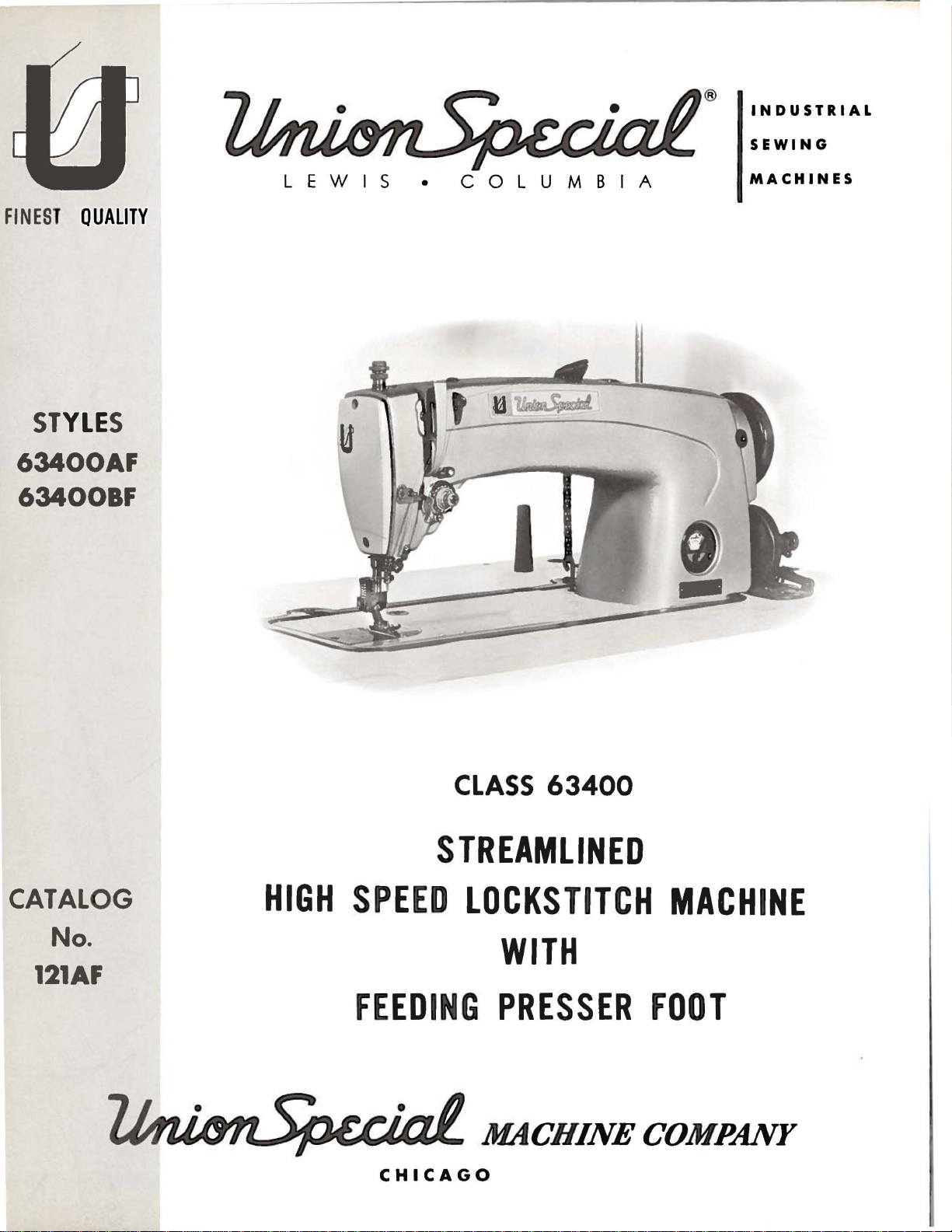
Page 1
®
INDUSTRIAL
SEWING
FINEST QUALITY
ST
YLE
S
63400AF
63400BF
LEWIS
•
COLUMBIA
MACHINES
CLASS
63400
STREAMLINED
CATALOG
No.
HIGH
SPEED
LOCKSTITCH
WITH
121AF
FEEDING
CHICAGO
PRESSER
MACHINE
FOOT
Page 2
(Supplement
Catalog
to
No.
Catalog
INSTRUCTIONS
FOR
121
AF
No.
121
M)
ADJUSTING
LIST
Streamlined
63400
First
AND
OF
CLASS
Styles
AF
OPERATING
PARTS
63400
Lockstitch
63400
Edition
BF
Union
Rights
Copyright
by
Special
Reserved
1971
Machine
in
All
MACHINE COMPANY
INDUSTRIAl
Printed
SEWING
CHICAGO
in
2
MACHINES
U.S.
Co.
Countries
A.
July,
1971
Page 3
IDENTIFICATION
OF
MACIDNES
Each
the
machine.
numbers
Example:
only
minor
Style
number.
Styles
which
differs
"Class
This
junction
not
used
Opposite
number,
NOTE:
Adjusting
those
ions
B.
in
included
or
are
Union
Style
have
"Style
changes
of
machines
63400".
catalog
therewith.
on
Styles
the
description
When
ordering
column.
and
Catalog
in
additional
Special
machine
numbers
one
or
more
63400
Example:
are
AF".
made
"Style
similar
from
the
style
is a supplement
Only
63400
those
A
illustration
and
amount
repairparts
operating
No.
121
M
this
catalog
instructions
is
identified
are
classified
letters
Special
suffixed,
Style
in a standard
63400
in
AFZ".
construction
number,
APPLICATION
to
Catalog
parts
and B are
page.
which
illustrated
parts
required.
always
instructions
for
Styles
are
that
the
63400
ones
pertain
by a Style
as
standard
but
never
numbers
machine. a "Z"
are
grouped
in
that
OF
are
are
use
for
A
that
it
contains
CATALOG
No.
121
used
and
on
listed
identified
the
part
Styles
63400
and B respectively.
are
different
specifically
number
and
contain
is
M
and
Styles
number
AF
from
to
Styles
on a name
special.
contain
the
suffixed
the
letter
to
under a class
no
letters.
should
63400
at
the
by
be
AF
back
detail
listed
and
BF
are
The
Styles
63400
plate
Standard
letter
"Z".
the
Standard
number
Example:
used
and
of
in
BF.
this
number.
in
the
similar
only
instruct-
63400
AF
and
on
Style
"Z".
When
con-
but
book.
part
second
to
A
and
BF.
This
herein.
this
from
It
class.
the
handwheel
High
Speed
Medium
Button
matic
matic
for
Stitch
Lubricating
Head
Take-up
Equipped
Work
63400
Space
AF
work,
stitches
recommended
63400
BF
weight
Specify
Maximum
catalog
can
also
Reference
operator's
is
toward
Streamlined
and
Heavy
Regulator,
Oiling.
Lever
with
Feeding
to
Right
For
miscellaneous
1
9/64
per
For
miscellaneous
work.
stitches
recommended
applies
be
the
Duty.
System.
Needle
and
of
inch
inch,
speed
1
13/64
specifically
applied
to
direction.
position
operator.
Long
Drop
Stitch
Needle
Presser
Needle
needle
thread
5500
inch
per
inch,
with
while
STYLES
Arm
Feed,
Length
Head
Oil
Bearing
Bar
Foot
Bar
plain
bar
travel.
size,
R.
P.
plain
needle
thread
speed
to
the
discretion
such
as
seated
OF
MACHINES
Lockstitch
Rotary
Indicator.
Siphon,
Adjustable
Driving
and
Rotary
11
1/8
Inches.
seaming
Type
needle
M.
seaming
bar
travel.
size,
5500
R.
Standard
to
some
right.
at
left,
the
Hook,
Adjustable
Feed
Link,
Feed
Needle
operations
180
type
and
operations
Type
needle
P.M.
Styles
Special
front.
machine.
Machines,
Horizontal
One
Reservoir
Hook
Eccentric,
Timing
Thread
on
light
GXS
or
180
size
and
on
medium
180
GXS
type
and
of
machines
Styles
back,
etc
Operating
One
Needle,
Hook
Enclosed
Oil
Control.
Needle
on
Lower
Tension,
and
medium
GYS
needle.
edge
guide.
and
or
180
size
and
as
of
machines
.•
are
dir2ction
Shaft,
Bearin
Main
Maximum
Maximum
medium
GYS
edge
listed
in
given
of
Light.
Push
AutoAuto-
gs
Shaft.
weight
Specify
heavy
needle.
guide.
3
Page 4
NEEDLES
Each
denotes
number,
sured
the
size
needles
Needle
The
description
Type
180
180
No.
GXS
GYS
To
sample
on
label.
Selection
used.
stitch
formation.
Union
the
kind
stamped
in
thousandths
number
packaged
Type
have
needle,
A
complete
Thread
Special
of
on
needle
shank,
the
of
an
represent
and
sold
180
GXS
and
sizes
Round
groove,
shank,
wide
chromium
Round
groove,
shank,
wide
plated -sizes
needle
or
orders
the
type
order
of
the
proper
should
pass
point,
needle
inch
the
by
Union
or
180
available
round
angle
plated
round
angle
029,
promptly
and
would
needle
freely
has
both a type
length,
shank,
across
complete
Special.
GYS
are
are
point,
groove,
-
sizes
point,
groove,
032,
size
number
read:
size
through
and a size
groove,
denotes
the
eye.
symbol,
finish
largest
Collectively,
which
recommended
listed
below.
Description
lockstitch,
struck
029, 032, 036,
lockstitch,
struck
036,
and
040, 044,
accurately
should
"1000
should
the
Needles,
be
needle
number.
and
diameter
is
for
Styles
and
Sizes
short
groove,
040,
short
groove,
049,
filled,
be
forwarded.
Type
determined
eye
in
order
other
the
given
length,
deep
044, 049,
length,
deep
054,
an
180
by
The
type
details.
of
the
type
on
the
63400
ball
spot,
The
blade,
number
label
AF
eye,
ball
054,
ball
eye,
spot,
chromium
060.
empty
Use
GXS,
the
to
package,
description
Size
size
of
produce a good
number
size
mea-
and
of
and
BF.
single
point,
060.
single
".
036
thread
all
a
11
•
The
size
the
size
The
of
thread.
above,
than
Cotton
of
the
thread
which
size
strength
employed.
of
the
needle
following
The
choice,
may
specified.
Thread
Size
0
30
36
40
50
60
70
80
SELECTING
requirement
The
employed.
table
shows
however,
dictate
the
THE
of
the
quality
the
preferred
should
selection
Mercerized
SIZE
seam
of
produced
the
work
OF
size
give
of a needle
Size
B
A
A
0
00
000
0000
THE
NEEDLE
is
largely
desired
of
needle
consideration
size
slightly
Thread
dependent
is
largely
for a given
to
factors
larger
upon
dependent
size
and
referred
or
Needle
Size
060
054
to
060
048
to
054
044
to
048
044
to
048
040
to
044
to
to
040
036
036
032
the
upon
_,
kind
to
smaller
90
0000
100
4
032
028
to
to
036
032
Page 5
IDENTIFYING
PARTS
Where
Parts
which
too
distinguish
Part
numbers
appear.
IMPORTANT!
OF
MACHINE
The
arrangement
replacement
An
exploded
Styles
The
position.
their
view
listed
plate
part
being
presents a sector
On
the
construction
small
for a complete
FOR
parts
view
in
this
the
page
numbers.
shown.
one
part
represent
ON
ALL
WHICH
of
for
Styles
plate
catalog
opposite
descriptions
permits,
catalog
from
the
another
same
ORDERS,
PART
IS
ORDERING
this
catalog
63400
at
the
back,
and
Styles
of
the
machine,
the
illustration
and
each
stamping
that
part.
PLEASE
ORDERED.
OF
REPAIR
is
to
facilitate
AF
and
BF.
covers
63400 A
parts
the
number
part
is
stamped
are
is
similar
regardless
INCLUDEPART
PARTS
easy
the
differences
and B covered
being
will
be
found a listing
of
pieces
with
identified
in
appearance.
of
the
and
in
aligned
as
required
its
part
number.
by
letter
catalog
in
symbols
which
NAMEANDSTYLE
accurate
between
Catalog
in
of
their
the
in
the
ordering
the
Standard
No. 121 M.
assembled
parts
particular
they
of
with
Numbers
the
position
in
ordering
exploded
Sub-assemblies.
or a solid
can
be
furnished
description
Success
Union
Special
Company,
to
the
most
Maximum
Genuine
parts
are
guarantee
in
of
the
parts.
view
line
of
plate
box
the
in
the
Needles
its
subsidiaries
approved
efficiency
needles
stamped
of
the
the
first
part
Always
carries
which
on
the
for
repairs,
main
USE
operation
and
are
with
highest
column
in
the
illustration.
use
the
a
reference
are
sold
picture
are
sub-assembly.
GENUINE
of
these
and
Repair
and
authorized
scientific
durability
packaged
the
Union
quality
in
are
reference
part
number
number
complete,
plate.
Component
indicated
NEEDLES
machines
Parts
as
distributors.
principles,
are
assured.
with
labels
Special
materials
TERMS
numbers
Reference
listed
for
or
by
by
indenting
AND
REPAIR
can
furnished
and
are
marked
trade
and
mark.
workmanship.
numbers
each
separate
parts
their
be
by
They
made
~
only,
and
should
in
the
second
part
available
part,
of
sub-assemblies,
descriptions
PARTS
secured
the
Union
are
designed
with
Each
utmost
trade
merely
never
are
only
Special
.
Genuine
mark
indicate
be
used
column.
for
The
sale.
in a bracket
which
under
with
the
genuine
Machine
according
precision.
repair
is
your
Prices
are
forwarded
otherwise
are
strictly
f.
o.
directed.
b.
shipping
A
charge
net
cash
is
and
point.
made
subject
Parcel
to
cover
5
to
change
Post
the
shipments
postage
without
and
notice.
are
All
insured
insurance.
shipments
unless
Page 6

INSTALLING
CAUTION!
on
handwheel.
Before
carefully
packing
A
attaching
packed.
box,
bag
screw,
miscellaneous
the
Insert
upper
hinge
frame
Included
ing
one
bobbin
its
clamp
and
screw,
essential
spring,
when
When
Using
leaving
both
factory,
After
the
following
PREPARATION
of
assembly
one
attachments
studs
eyelet
also
with
winder
one
four
isolator
setting
unpacking,
hands
each
the
machine
steps
parts,
extra
in
(A,
bobbin,
to
holes
Fig.
the
STANDARD
each
machine,
assembly,
knee
lifter
pads
up
the
machine.
DO
on
bed
Union
should
OF
MACHINE
consisting
bed
provided
2A).
is a box
the
machine
assembly
and
clips,
NOT
lift
machine
casting,
Special
and
accessories
be
followed:
FOR
of
one
two
hinge
plate,
for
is
packed
them
ACCESSORIES
of
STANDARD
mounting
and
its
and
one
out
of
lift
gently.
machine
is
have
INSTALLATION
frf3_me
studs
thread
and
with
in
rear
of
ACCESSORIES--contain-
frame,
rubber
machine
pad,
rest
box
sewed
been
two
each
cloth
one
bed
pin.
by
placing
off,
inspected
removed
eyelet,
screws
machine.
plate.
oil
drain
positioning
These
one
from
one
eyelet
for
holding
Assemble
jar
spring
parts
hand
and
the
and
are
Lockstitch
the
bed
On a
cut-out
through
over
the
nuts
right
retaining
lightly.
Place
1/16
inch
taining
of
the
Tip
shown.
must
not
plate
sui~abl
with
left
hinge
hinge
sewing
clearance
plate
board
machine
All
end
bind.
machines
is
FLUSH
.
e
tableboard,
the
hinge
pad
pad;
plate
smartly
and
tighten
back
play
TABLE
are
with
installed
the
top
of
in
the
MACHINE MOUNTING
lugs
and
tighten
insert
(21393 R)
head
in
between
upward
locking
against
of
the
place
to
the
round
to
the
frame
the
with a hammer
cross
machine
rear
securely.
head
outside
mounting,
cloth
nuts
securely.
rest
pin,
shaft
(Fig.
wood
front
plate
should
TOPS
table
machine
FRAME
mounting
1).
Assemble
screw
of
edge
to
and
assemble
be
tops,
prepared
mounting
INSTALLATION
Insert
pan
and
and
frame
bed
and
section,
after
the
(21393
the
countersunk
positioning
tighten
being
frame
insure a good
the
knee
taken
up
by
with
frame.
securely.
as
shown,
sure
sides,
grip
press
the
cone
cut-out,
N)
in
spring
there
on
the
assembly
bearings,
so
the
machine
wood
screw
(63474
Assemble
and
snug
is
rap
the
underside
that
A)
up
about
re-
as
but
6
Page 7

MACHINE
MOUNTING
FRAME
INSTALLATION
(Continued)
Before
lifter
maximum
in
raises
located
in
the
pulley
the
under
121
al
"THREAD
rod
the
head.
approximately
The
directly
operation.
mechanism
of
belt
to
"Winding
M.
These
Thread
requirements.
the
machine
should
lift
bobbin
the
wind
machines
machine
CONTROL".
be
of
the
This
winder
in
The
to
winder,
the
the
adjusted.
presser
may
5/16
front
base
be
moved
when
bobbin.
Bobbin",
are
as
has
been
is
put
The
bar
be
done
inch.
should
of
the
sewing
of
the
winder
closer
in
operation,
Regulation
under
equipped
indicated
enlarged
Needle
into
production,
left
stop
and
its
by
setting
BOBBIN
be
secured
machine
has
to
and
OPERATOR'S
BELTS
to
use
THREADING
in
Fig.
for
is
threaded
screw
parts
WINDER
to
two
or
farther
should
operation
either
2A.
clarity
from
the
(22597
do
not
the
stop
the
table
belt
elongated
exert
#1
Check
and
left
bell
crank
F)
interfere
screw
top
and
will
bear
attaching
away
of
INSTRUCTIONS,
"Vee"
spring
from
only
the
bobbin
or
threading
described
to
right.
(21665
should
with
so
that
so
that
against
belt
enough
winder
round
under
J)
be
set
moving
the
its
pulley
holes,
as
pressure
in
belts.
with
paragraph
of
the
so
that
parts
presser
will
the
belt
which
needed.
against
is
described
Catalog
dimension-
knee
the
with-
bar
be
when
allow
The
No.
on
6347
'
21393N
6
} 16630
660-
168
Fig.
1
\ '-651-16
"'-213
93S
6
3476
61477
C
7
Page 8

OILING
CAUTION!
the
reservoir
Fill
oil
is
be
added
straight
in
the
Oil
left
in
The
of
the
arrow
the
flow
It
long
period,
parts.
Run
machine
speed
Oil
has
main
at
maximum
when
mineral
main
may
the
oil
quantity
machine
must
reservoir
reservoir.
be
reservoir
be
level
needle
oil
drained
of
just
of a Saybolt
oil
below
(counterclockwise)
of
oil.
is
recommended
be
lubricated
After
operation
oiling,
slowly
can
replace
for
then
been
filled
at
before
plug
when
is
in
yellow
This
from
cover.
supplied
the
increases
that a new
by
head
several
be
expected
drained
screw
needle
band
viscosity
is
equivalent
main
reservoir
to
the
cloth
the
machine,
removing
cover
minutes
from
starting
(B,
is
in
marked
hook
plate.
oil
as
to
without
the
main
to
operate.
Fig.
2A)
yellow
"LOW".
of
90
to
Union
by
is
controlled
Turning
flow
and
or
one
the
head
no
further
distribute
damage.
reservoir
and
check
band
marked
Use a stainless
to
125
seconds
Special
removing
plug
by
the
dial
in a clockwise
that
has
cover
and
hand
oil
to
before
oil
level
"FULL".
at
100°
specification
screw
dial
located
in
the
direction
direction
been
out
oiling
oiling
the
will
various
shipment
at
gauge
Oil
water-white
Fahrenheit
located
on
decreases
of
service
all
the
be
required.
parts.
should
No.
on
the
front
of
for
moving
and
(C);
175.
the
the
a
Full
WR
AP
THREAD
ROTARY
2
1/2
TURNS
THEN
POST
THREAD
EYELET
TENSION
AROUND
DISC
CLOCKWISE
TENSION
Fi
g. 2A
8
Page 9

The
adjusting
63400 A and B covered
instructions
INSTRUCTIONS
for
Styles
in
Catalog
TO
No.
SET
121 M,
THE
FOR
63400
FEED
MECHANICS
AF
and
BF
with
the
additions
TIMING
are
the
same
as
follows:
as
for
Styles
NOTE:
needle
the
screws
gauge.
needle
Hold
the
mark
eccentric
on
screws
sure
lower
ing.
ADJUSTING
feed
in
both
feed
should
above
stroke.
plunger
right
While
wheel
regulating
slot
plunger
ting
and
stitch
The
be
set
To
reset
and
oil
gauge.
through
Turn
bar
the
lower
"9"
on
the
bed
in
that
main
The
feed
slots
directions,
as
well
rise
the
To
(located
and
rear
holding
in
operating
of
feed
down,
direction
in
opposite
length.
feed
eccentric
at
"9
".
the
large
handwheel
lines
there
of
throat
change
finger
plug
Loosen
the
the
is
at
the
main
casting
the
shaft.
FEED
eccentric.
shaft
the
adjustable
up
lower
is
Recheck
dog
must
the
throat
as
in
approximately
plate
the
in
of
needle
plunger
is
turn
to
increase
direction
Release
timing
feed
MECHANISM
direction
timing,
screw
the
hole
handwheel
securely
with
wall.
no
across
the
stitch
the
felt
handwheel
located
lower
below
top
of
until
the
Retighten
sprocket,
end
the
be
centered
plate
line
at
the
length,
bed
bar)
down,
to
drop
Continuing
the
to
decrease
plunger.
its
the
feed
timing
play
hook
and
the
of
3/64
top
base
in
turn
until
in
stitch
line
remove
below
sprocket
the
until
and
the
stroke.
turn
timing
driving
line
the
being
in
the
tim-
in
the
leveled
line
feed.
inch
of
its
press
to
the
firmly.
handstitch
into
the
to
hold
opera-
length
the
to
oil
of
It
.
Stitch
uations
ed
through
next
to
Adjust
threads
lengths
on
the
the
the
handwheel.
the
are
visible
are
indicator
window
ADJUSTING
presser
above
indicated
dial
and
in
the
spring
the
by grad-
are vie
belt
guard
THE
regulator
bed
casting.
w-
FEEDING
(A,
Fig.
9
PRESSER
16A)
so
Fi
g.
16A
FOOT
that
approximately
thr
ee (3)
Page 10

ADJUSTING
THE
FEEDING
PRESSER
FOOT
(Continued)
Back
flat
on
adjusting
Tighten
the
lock
off
throat
lines
nut
stop
on
screw
plate
the
(D).
(B)
and
presser
in
feed
foot
feeding
dog
bottom,
presser
down,
adjust
line
foot.
up
With
stop
with
the
nut
the
centerline
(C.
presser
Fig.
foot
16A)
of
the
resting
until
needle.
the
Loosen
presser
lifter
above
machine
screw
or
the
required
the
the
adjust
needle
lever.
Set
left,
lock
guide
needle
Remove
bar
the
the
back
in
the
the
nut
to
stop
slot
screw
(G),
presser
throat
lifter
proper
to
reset
and
before
nut
nut
will
depress
plate
against
lever
setting
lock
the
presser
tightening
(A.
(C)
so
not
(E.
Fig.
bar
seat
the
the
stop
presser
bar
Fig.
that
touch
16A)
presser
connection
(See
rest
pin.
bell
crank
for
the
screw
bar
guide
connection.
screw
18C)
when
the
and
the
needle.
Fig.
in
presser
foot
(A.
Fig.
loosening
(61468
presser
in
place.
(E).
presser
presser
lifter
Fig.
16B).
(F.
be
Lock
10
16B
bar
lever
16B)
This
F).
By
bar
connection
Release
Fig.
sure
spring
foot
in
guide
and
so
is
the
lock
turning
1)
allowing a 1/16
the
presser
(B)
is
pushed
position
(F),
while
retighten
its
top
accomplished
nut
and
the
stop
is
accomplished.
pressure
foot
of
the
feeding
forward.
with
lock
holding
screw
surface
relocating
screw
on
presser
inch
is
in
presser
nut
down
(E).
Release
is 5 1/8
by
tipping
the
to
the
Retighten
spring
space
alignment
the
rear
(D).
between
foot
Replace
inch
stop
right
with
and
of
on
the
as
the
Page 11

ADJUSTING
THE
FEEDING
PRESSER
FOOT
(Continued)
presser
between
stop
screw
of
1164
Lift
Should
loosen
18C)
as
spring
the
inch
feeding
adjustment
screw
required
top
(F)
on
(B)
in
throat
in
and
of
the
feeding
presser
be
bottom
to
obtain
adjusting
yoke
plate
(E)
foot
so
when
foot
and
necessary,
of
presser
proper
nut
and
top
that
foot
check
remove
foot
position.
(A)
on
of
presser
is
lifted
to
shank
presser
spring
foot
with
see
if
the
presser
to
Retighten
foot,
(B)
with
bottom
bottom
reposition
feed
screw.
slides
dog
foot
and
the
down.
is
parallel
leveling
adjust
feed
rearward a maximum
from
dog
to
the
spring
to
45164
down.
throat
machine
(G,
inch
Adjust
plate.
Fig.
and
Set
to
top
Set
1
I 64 ,;.nch
thread
the
thread
spring
check
thread
Thread
thread
tension
Set
spring
bottom
ine
is
at
Set
light
being
as
sure
Fig.
needle
of
cloth
tension
running
not
spring
pull-up
machine
2 112
dis
check
overthrows
of
speed.
needle
possible
plate
clearance
pull-up
threaded
times
c.
spring
checkspring
check
thread
post
from
bracket,
1 I 2
bracket
as
clockwise
and
bobbin
to
spring
18C
THREAD
pull-upbracket4
(See
Fig.
eyelet
between
the
(See
inch
shown.
tension
threadline
motionwhen
produce a good
is
so
rotary
with
Fig.
above
(See
around
so
thread
acting
16A).
there
it
tension
the
18D).
bottom
Fig.
Wind
that
slightly
tension
properly.
is
and
check
18E).
needle
rotary
check
mach-
stitch
CONTROL
19/32
the
to
Set
of
at
as
inchfrombottom
a
Fig.
(underside)
Fig.
18E
18D
ofbracket
may
to
feed
When
have
the
sewing
to
be
bottom
various
changed
ply
materials,
to
faster
get
good
and
vice-versa.
the
ply
matching.
pressure
11
of
Increasing
the
feeding
the
foot
presser
pressure
spring
will
tend
Page 12

12
Page 13

The
are
used
Use
catalog.
parts
on
Styles
Catalog
illustrated
63400
No.
121 M
on the
AF
and
BF,
(Styles
opposite
but
63400 A or
page
not
used
and
on
B)
described
Styles
for
all
on
this
not
page,
illustrated
63400 A or B respectively.
parts
represent
or
the
described
parts
in
that
this
Reference
descriptions,
Ref.
No.
1
3
5
9
10
11
12
13
14
15
16
17
18
19
20
21
22
23
24
25
26
27
28
29
30
31
32
33
33A
34
35
36
37
38
39
39A
40
41
42
43
44
45
46
47
48
49
50
51
52
53
54
55
56
57 73 c
Part
No.
63457
63457
2
61257
51257
4
63957
21390
6
7
8 57
57 WD
57
22564
63471
63471
90
12935
63992
HS24 C
22513
63970
29475
660-269
63992
22560
63492
63492
63453
61492
61492
61492
63492
61292
61405
61424
63420
63420
63430
22785
22560
63430
56330
63430
63430
22799
22798
56330
56330
56330
56330
604
52930
51430
61377
41071
563
30
63430
61405
61424 AB-063
63459
22570
AP
s
AB
A
AS
AJ
AG
AF
AC
F
Q
G
AD
v
AB
B
numbers
indicate
M
L
G
G
A
BE
we
WB
B
A
A
A
A
BE
A
G
A
B
N
T
s
H
C-4
c
AA
AA-063
J
H
u
B
T
w
that
are
they
are
Lock
Stop
Nut
Presser
Presser
Presser
Nipper
Screw,
Nipper
Nipper
Screw--------------------------------------------------------
Nipper
Nipper
Screw,
Screw,
Tension
Screw-----------------------------------------------------------Screw,
Thread
Rotary
Quad
Tension
Tension
Tension
Take-up
Felt
Rotary
Tension
Tension
Tension
eed Dog, 22
F
hroat
T
Presser
Pr
esser
Yoke---------------------------------------------------------
Presser
Presser Foot
Presser Foot Bottom,
Hin
Screw,
Hin
flin
Regulating Screw---------------------------Link Hin
Scr
Cha
N
Washer
Lock
Compressi
Regulating
F
eed Dog,
Throat
P
ress
Screw-------------------------------------------------------Screw--------------------------------------------------------
inside a bracket
component
Nut
---------------------------------------------------------
---------------------------------------------------------
Spring
Bar------------------------------------------------------
Bar
Spring Assembly
for
Spring------------------------------------------------Spring Plate
Base
Spring
for
nipper
for
tension
Post
for
thread
Pull-up
Needle
Ring ----------------------------------------------------
Set
\Vas
Tension
Plate, . 063 inch
Foot,
Foot, for
Screw---------------------------------------------------Screw----------------------------------------------------
Bu
shing
63420
J - -
63420
1-I----------------------------------------------------- 1
ge
Pin
for
ge
Spring ----------------------------------------------
ge P
in---------------------------------------------
ew, f
in
Cutting
ut
---------------------------------------------------------Nut
22 t e e
Plate, . 063
er
Bar Gui
parts
Regulator
Bushin
Socket
Post
Screw
Post
Release
Spring ----------------------------------------------her
Release
Spring-----------------------------------------------Nut
Foot
g,
lower
nipper
Bracket--------------------------------------------
Tension
teeth
for
spring---------------------------------------
-------------------------------------------------Mounting Bracket
spring assembly----------------------------------
assembly
Eyelet
pull-up
Socket
------------------------------------------------
------------------------------------------------P 'n
-------------------------------------------------Disc
Washer---------------------------------------
--------------------------------------------------
per
wide
nar
r ow
Link, marked
-------------------------------------------------Bottom,
---------------------------------------------------
Screw----------------------------------------------
hinge spring
ge
Screw----------------------------------------------
or chain cut
Knife,
------------------------------------------------------
----------------------------------------------------on
Spring -------------------------------------------
Nut
--------------
th
per i
inch needle hole, for
de------------------------------------------------
or
box
on
the
of a complete
Description
and
Bushing-------------------------------
---------------------------------------
- -
-----------------------------------------
-------------------------------------------
--------------------------------
---------------------------------------
----------------------------------------
bracket-----------------------------------
Assemb
inch,
needle
feed
tin
nch, for
ly
-----------------------------------
-------------------------------------------
------------------------------------------
------------------------------------------
for
wide
hol
combination
feed com
m a r k
marked "BU",
----------------------------------------
g knife
ma
r ked "D"
feed
e,
for
bination
"C"
--------------------------------
ed
"BV", for
---------------------------------
--------------------------------
-
---------------------------------
narr
ow f
picture
part
or
combination
wide
----------------------------
--------------------------
for
eed
narrow feed com
assembly.
feed
pre
presser
combination-------------
plate
combination
sser foot
-
and
have
---------------
foot
-----------------
binati
--------
o.
No.
-
on
-------
------
indented
Amt.
Req.
1
1
1
1
1
1
1
1
1
1
1
1
1
1
1
1
1
1
1
1
1
1
1
1
1
2
1
1
1
1
1
1
1
1
1
1
2
1
1
1
1
1
---1
1
1
1
- - 1
1
1
1
1
1
1
1
1
1
1
1
13
Page 14

BOOST
PRODUCTION
WITH
WORK
UNION
THESE
AIDS
SPECIAL
FROM
PNEUMATIC
conventional Class
scissor-action
posi
live
AIR
FABRIC
signed
to
remove curls
knit materials as fabric passes
area. Style
CHAIN-CUTTER-lor
mechanism
cut.
Style
2899
lor
UNCURLER-This
Class
39500
from
2899
B-1
39500
and
that
A-1
machines, uses air jets
top
and bottom plies of
39600
is
a durable
makes a clean
"--"
unit,
through
use on
de·
flat
sewing
PNEUMATIC
operated
machines
simply by knee-touch ing an actuating
CHAIN
CUTTER-
small pneumatic chain cutter that is available
lor
Installat ion as an accessory
:16200
Flalseamers. Style 2899A-6
FOOT
fool
lifter
lor
allows
use on Class
the operator to raise the
The above photo
LIFTER-The
shows
unit
on
39500
loot
switch
Class
air-
the
.
KNIFE
GRINDER
kn
ives, is simple and easy to operate, elimi-
type
nates defective g11rments caused
sharpens
straight
by
dull knives.
®
u
II
NISTQUALITY
MACHINE
ELECTRONIC
wheel
to
insurmg better
move the needle
NEEDLE
control,
uniform quality and increased
up
or
down
POSITIONERS
AMCO
or
angle
..• this allows
HEAT
DISPELLER-
unit (arrow) is an effective means
oil temperature where heavy duty service re-
quires i
t.
Style
el
iminate
the
operator
necessi
the
production.
Union Special's auxiliary
2899
E-1
ty
of
to
reaching
keep both hands on
lor
lor
reducing
the
hand·
the
work,
Page 15

Helpful,
cient
types
machine
Promotion
Sales
esting,
obligation
illustrated
authoritative
of
equipment
sewed article
are the
Department.
bulletins
following:
information
for
is
available
Among
that
on
the
making
are available
from
virtually
Union
the
many
most
effi
Special's
inter-
without
any
-
HERE
ARE
HELPFUL
No.
240,
"Men's,
No.
249,
"Rainwear"
No.
250,
"Men's
No.
251,
"Service
No.
252,
"Men's
No.
253,
"Overalls, Coveralls, and Dungarees"
No.
254,
"Men's
No.
256,
"Knit
No.
259,
"Men's
No.
260,
"Work
No.
262,
"Cotton,
No.
263,
"Men's
No.
264,
"Men's
No.
265,
"Women's
No.
266,
"Women's
No.
267,
"Corsets, Girdles, Brassieres"
No.
268,
"Children's
No.
269, "Mattresses,
Upholstery"
No.
271,
"Awnings,
No.
273,
"Curtains & Drapes"
No.
610,
"Kiipp-it"
No.
710,
"MCS
No.
730,
"MCS
Hemmer"
No.
740,
"MCS
No.
750,
"Fusing
No.
1100,
No.
1105,
"Columbia
ing
Machines"
No.
1500,
Women's,
Dress
Shirts
Shorts
Knit
Outerwear"
Sports
Gloves"
Bags"
"Lewis
stitch,
"Button
Blindstitch,
"Alteration
Burlap,
Clothing"
Women's,
ForMation
Automatic
Automatic
Presses"
Blindst
Machines"
Children's
Shirts"
and
Pants"
and Pajamas"
Underwear"
Shirts"
Jute,
and
Children's
Wear"
Wear
And
High
Wear"
Slip
Covers,
Canopies, Tents,
Unit"
Dual
Underfront
Rib-Knit
itch,
Chainstitch,
Sewers-
Ticket
Saddle
Stitch,
Department
Footwear"
Multiwall
Jackets"
Fashion"
Furniture
Tarps"
Cuff
Machine"
Lock-
Tackers"
and
Tie
Machines"
Paper
Shirt
Clos-
BULLETINS
TO
SEWING
HELP
PROBLEMS
YOU
and
CATALOGS
SOLVE
®
Page 16

,..o
...
...
'
0
WORLD'S
,..&lf
FINEST
QUALITY
*
INDUSTRIAL
SEWING
MACHINES
UNION
SPECIAL
maintains sales
and
facilities throughout the world. These offices
aid
you
in
the selection of the right sewing
equipment for your particular operation. Union
Special representatives
tory trained
promptly
tion, there
and
and
is
a Union Special Representative
serve you. Check with
ATLANTA,
BOSTON, MASS.
CHICAGO,
DALLAS,
LOS ANGELES, CAL.
NEW
PHILADELPHIA,
GA.
ILL.
TEXAS
YORK, N.
Y.
PA.
efficiently. Whatever your loca-
are
and
service men
able
to serve your needs
him
today.
MONTREAL, CANADA
TORONTO, CANADA
BRUSSELS, BELGIUM
LEICESTER,
LONDON,
PARIS, FRANCE
STUnG
ART, GERMANY
service
will
are
fac-
to
ENGLAND
ENGLAND
400
Representatives
MACHINE
N.
FRANKLIN
industrial
and
cities
distributors
throughout
COMPANY
ST.,
CHICAGO,
in
the
all
Important
world.
ILL.
60610
 Loading...