

Page 1
®
INDUSTRIAL
SEWING
FINEST QUALITY
STYLES
63400AB
LEWIS
•
COLUMBIA
MACHINES
CLASS
63400
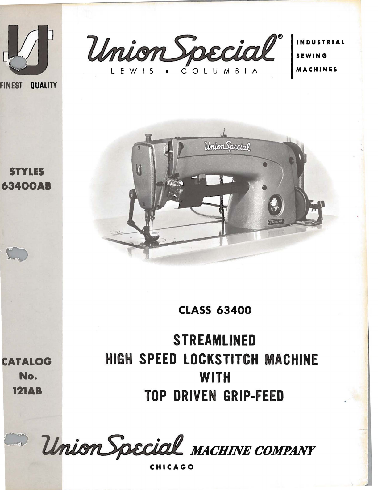
STREAMLINED
ATALOG
No.
121AB
HIGH
SPEED
TOP
CHICAGO
LOCKSTITCH
DRIVEN
WITH
GRIP-FEED
MACHINE
Page 2

Page 3
Catalog
(Supplement
No.
to
Catalog
INSTRUCTIONS
FOR
121
AB
No.
121
M)
ADJUSTING
Streamlined
Union
Rights
LIST
CLASS
63400
First
Copyright
Special
Reserved
AND
OF
Style
Edition
by
in
OPERATING
PARTS
63400
Lockstitch
AB
1970
Machine
All
Countries
Co.
August.
MACHINE
INDUSTRIAL
CHICAGO
Printed
1970
COMPANY
SEWING
in
MACHINES
U.S.
3
A.
Page 4
IDENTIFICATION
OF
MACHINE
Each
the
machine.
numbers
Example:
only
minor
Style
which
"Class
junction
on
certain
number,
NOTE:
Catalog
are
that
number.
Styles
This
Style
Opposite
Adjusting
the
pertain
Union
Style
have
"Style
differs
63400".
catalog
therewith.
63400 B
63400 B
description
When
column.
No. 121 M
ones
one
changes
Example:
of
machines
from
parts
the
ordering
and
that
specifically
Special
63400
are
is a supplement
Only
are
illustration
operating
for
are
machine
numbers
or
more
AB".
made
"Style
similar
the
those
illustrated
are
shown
and
amount
repair
Style
different
to
are
Special
style
APPLICATION
instructions
63400
Style
is
identified
classified
letters
in a standard
63400
in
number,
parts
in
pages,
required.
parts
from
63400
suffixed,
Style
ABZ".
construction
to
Catalog
which
and
listed
phantom
parts
always
B.
The
Style
AB.
by a Style
as
standard
but
never
numbers
machine, a "Z"
are
in
that
OF
CATALOG
No. 121 M
are
used
at
the
to
help
are
use
the
for
Style
only
instructions
63400
contain
grouped
it
contains
on
back
locate
identified
part
63400
B,
or
number
and
contain
is
and
Style
of
this
the
number
AB
are
on a name
special.
the
suffixed
under a class
no
should
63400 AB,
63400
by
detail
listed
are
included
additional
Standard
the
letter
to
letters.
be
book.
AB
similar
in
used
For
number,
in
plate
Style
letter
"Z".
the
but
parts.
the
to
this
instructions
"Z"
Whe
Standard
number
Example:
in
con-
not
used
clarity,
part
second
those
catalog
on
.
in
The
It
can
also
Reference
operator's
is
toward
High
One
Hook
Enclosed
Control,
Bearings
Main
63400
denotes
number,
sured
the
needles
Speed
Needle,
Shaft,
Shaft,
AB
as
vinyls,
1
13/64
SeamSpec.
speed
Each
in
size
catalog
be
to
position
the
Streamlined
Automatic
Automatic
for
For
5500
Union
the
kind
stamped
thousandths
number
packaged
applies
applied
direction,
operator.
Light,
Push
Take-up
Maximum
miscellaneous
foam
inch
301-SSa-1.
R.
Special
of
specifically
with
while
Long
Medium
Button
Lubricating
Head
Lever
Work
laminates,
needle
P.
M.
needle
shank,
on
the
of
an
represent
and
sold
discretion
such
bar
needle
as
seated
STYLE
Arm
and
Stitch
Oiling,
and
Space
seaming
travel.
Type
point,
inch
the
by
Union
has
to
the
to
some
right,
at
the
OF
Lockstitch
Heavy
Regulator,
System,
Needle
Needle
to
Right
operations
wash
shank,
across
complete
and
Top
180 GXS
NEEDLES
both a type
length,
denotes
Special.
Standard
Special
left,
the
front,
machine.
MACHINE
Machine,
Duty,
Bearing
Bar
wear,
driven
or
groove,
symbol,
Drop
Stitch
Head
Driving
of
Needle
and
grip-feed
180GYSneedle.
and a size
largest
eye.
Collectively,
Style
Operating
Length
Oil
Adjustable
on
material
finish
which
Styles
back,
with
Feed,
Siphon,
Link,
Bar
hard
and
diameter
of
to
number.
is
machine
of
machines
etc.,
direction
Top
Rotary
Indicator,
Adjustable
Feed
Feed
11
1/8
handle
made
independently
Maximum
other
the
given
as
are
given
Driven
Hook,
One
Eccentric,
Timing
Inches.
materials,
of
natural
The
details.
of
the
type
on
the
listed
in
of
recommended
type
blade,
herein
this
class
from
handwheel
Grip-
adjustable.
number
label
Feed,
Horizontal
Reservoir
Hook
Needle
on
Lower
such
fibers.
number
The
size
mea-
of aft
the
Oil
a J
.-.....__.
-....,--...
4
Page 5
NEEDLES
(Continued)
Needle
description
180
GYS
To
have
sample
on
label.
needle,
Selection
used.
stitch
Thread
formation.
The
size
of
thread
the
size
of
The
following
of
thread.
above,
than
the
which
size
Type
and
Round
groove,
chromium
Round
groove,
sizes
needle
A
complete
of
should
strength
employed.
the
needle
The
may
specified.
180
GXS
sizes
available
shank,
wide
plated -sizes
shank,
wide
028, 032,
orders
or
the
type
order
the
proper
pass
SELECTING
requirement
employed.
table
choice,
dictate
or
180 GYS
round
angle
round
angle
groove,
036, 040,
promptly
and
would
needle
freely
of
The
quality
shows
the
however,
the
selection
are
listed
point,
groove,
point,
size
read:
size
through
THE
the
preferred
should
is
recommended
below.
Description
lockstitch,
struck
028,
032,
lockstitch,
struck
044,
number
and
048,
accurately
should
"1000
should
the
needle
SIZE
seam
of
produced
the
work
OF
size
give
of a needle
and
Sizes
short
groove,
036,
040,
short
groove,
deep
054, 060.
filled,
be
forwarded.
Needles,
be
determined
THE
Type
eye
in
NEEDLE
is
largely
desired
of
needle
consideration
size
slightly
for
Style
length,
deep
spot,
044, 048,
length,
spot,
chromiumplated
an
empty
180 GXS,
by
the
order
to
dependent
is
largely
for a given
to
factors
larger
63400
ball
eye,
ball
AB.
single
point
054,
ball
eye,
single
package,
Use
description
size
".
036
size
of
thread
produce a good
upon
dependent
size
upon
and
referred
or
smaller
The
060.
11
the
kind
to
,
-
a
•
Parts
which
_......_.
~
.appear.
Cotton
Size
30 B
36
40
50 0
60
70
80
90
100
Where
too
small
distinguish
Part
numbers
Thread
0
the
construction
for a complete
one
represent
part
Mercerized
IDENTIFYING
permits,
catalog
from
another
the
same
Thread
Size Size
A
A
00
000
0000
0000
028
PARTS
each
part,
part
stamping
that
is
regardless
is
stamped
are
similar
with
identified
in
appearance.
of
the
catalog
by
Needle
060
054
to
048
to
044
to
044
to
040
to
036
to
032
to
032
to
to
its
part
letter
in
060
054
048
048
044
040
036
036
032
number
symbols
which they
.
IMPORTANT!
OF
MACHINE
FOR
ON
ALL
WHICH
ORDERS,
PART
IS
PLEASE
ORDERED.
INCLUDEPART
5
NAME
ANDSTYLE
Page 6

The
arrangement
replacement
parts
for
ORDERING
of
this
Style
63400
catalog
AB.
OF
is
to
REPAIR
facilitate
PARTS
easy
and
accurate
ordering
o
Exploded
Style
plate
listed
presents a sector
position.
their
view
part
being
Numbers
the
position
in
ordering
exploded
Sub-
assemblies,
or a solid
can
be
furnished
description
view
in
this
On
the
numbers.
shown.
in
of
the
parts.
view
line
of
plate
box
the
plates
catalog
page
opposite
descriptions
the
first
part
Always
carries
which
on
the
for
repairs,
main
USE
at
the
back,
and
Style
of
the
machine,
the
and
column
in
the
illustration.
use
the
a
reference
are
sold
picture
are
plate.
indicated
sub-assembly.
GENUINE
NEEDLES
cover
63400 B
parts
illustration
the
number
are
reference
Reference
part
number
number
complete,
Component
the
covered
being
will
or
by
indenting
AND
differences
in
aligned
be
found a listing
of
pieces
numbers
numbers
listed
for
by
in
each
separate
parts
their
REPAIR
between
Catalog
as
in
required
only,
and
should
the
second
part
available
part,
of
sub-
descriptions
PARTS
the
No. 121 M.
their
of
in
assembled
the
parts
the
particular
merely
never
column.
for
are
in a bracket
assemblies,
under
Standard
Each
with
indicate
be
used
Each
sale.
which
the
Success
Union
Special
Company,
to
the
most
Maximum
Genuine
parts
are
guarantee
Prices
are
forwarded
otherwise
in
the
Needles
its
subsidiaries
approved
efficiency
needles
stamped
of
the
highest
are
strictly
f.
o.
directed.
operation
and
scientific
and
durability
are
packaged
with
the
quality
net
b.
shipping
A
charge
of
Repair
and
authorized
Union
cash
is
these
Parts
principles,
are
with
Special
in
materials
TERMS
and
subject
point.
made
Parcel
to
machine
as
furnished
distributors.
and
assured.
labels
marked
trade
and
to
Post
cover
6
can
be
secured
by
the
They
are
made
~.
mark.
workmanship.
change
without
shipments
the
postage
are
with
Each
and
only
Union
Special
designed
utmost
trade
notice.
are
insured
insurance.
with
according
precision
Genuine
mark
All
shipment
genuine
Machine
repair
is
your
unless
.
-----
Page 7

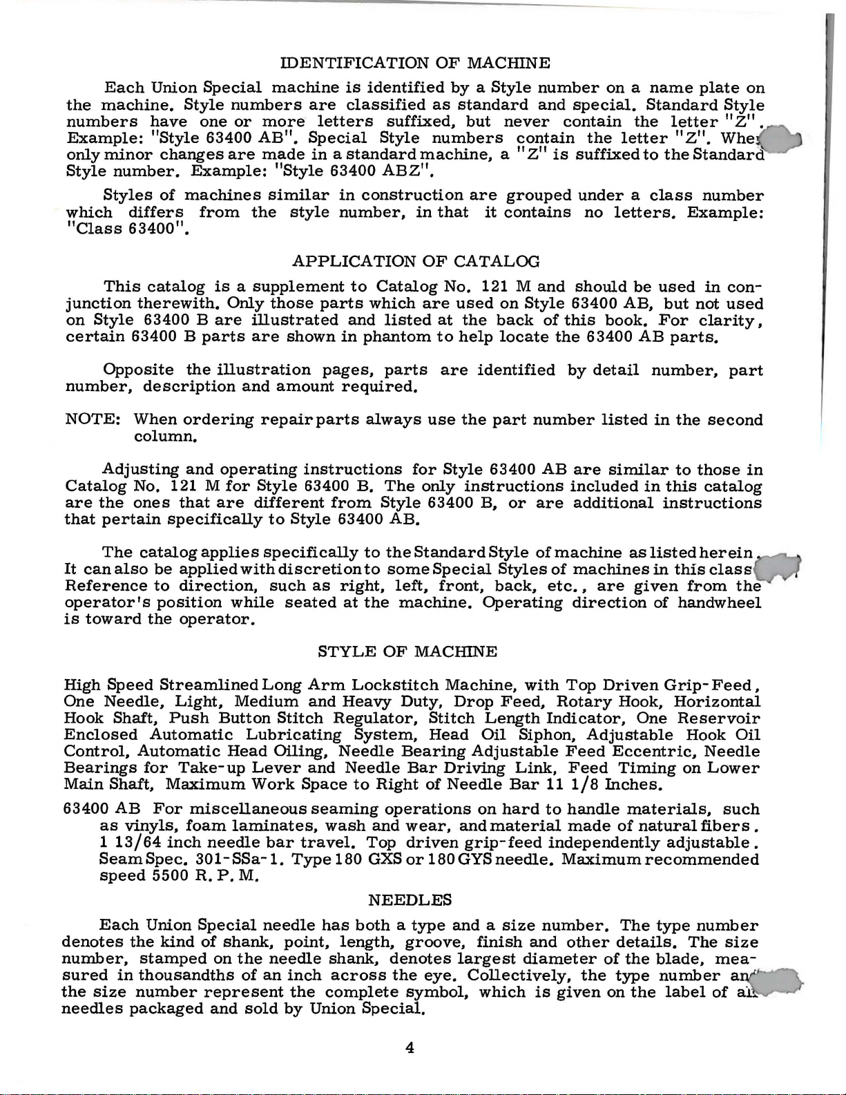
INSTALLING
CAUTION!
n
handwheel.
Before
carefully
packing
A
attaching
miscellaneous
Insert
the
upper
Includedalsowith
ing
one
its
clamp
and
screw,
essential
packed.
box,
bag
of
screw,
hinge
frame
bobbin
spring,
when
When
Using
leaving
the
PREPARATION
assembly
attachments
winder
four
setting
both
factory,
After
following
one
studs
eyelet
one
isolator
unpacking,
hands
each
the
machine
steps
parts,
extra
in
(A,
eachmachine
assembly,
knee
up
bobbin,
to
the
holes
pads
the
provided
Fig.
STANDARD
lifter
and
machine.
DO
NOT
on
bed
casting,
Union
should
OF
consisting
bed
2A).
the
assembly
clips,
Special
and
be
MACillNE
two
plate,
is a box
machine
lift
machine
lift
gently.
machine
accessories
followed:
FOR
of
one
hinge
is
for
them
ACCESSORIES
of
STANDARDACCESSORIES--contain-
mounting
and
its
and
one
INSTALLATION
frame
studs,
packed
machine
with
in
rear
rubber
out
of
is
have
thread
and
of
frame,
pad,
rest
box
sewed
been
two
each
cloth
one
bed
pin.
by
placing
off,
inspected
removed
eyelet,
screws
machine.
plate.
oil
positioning
for
drain
These
one
hand
from
one
eyelet
holding
Assemble
jar
and
spring
parts
are
and
the
Lockstitch
the
bed
On a suitable
cut-out
through
over
the
nuts
1/16
taining
of
shown.
must
right
retaining
lightly.
Place
inch
the
board
Tip
not
plate
with
the
left
hinge
hinge
sewing
clearance
plate
and
machine
All
end
bind.
machines
is
FLUSH
MACHINE MOUNTING
tableboard,
hinge
pad
pad;
plate
head
smartly
tighten
back
play
are
with
lugs
to
and
tighten
insert
(21393 R)
in
the
between
upward
locking
against
of
the
cross
TABLE
installed
the
top
place
the
rear
securely.
round
to
the
head
outside
frame
cloth
with a hammer
nuts
rest
shaft
in
of
the
machine
(Fig.
wood
front
mounting,
plate
securely.
pin,
should
TOPS
table
machine
FRAME
mounting
1).
Assemble
screw
of
edge
to
and
assemble
be
tops,
Insert
pan
and
insure a good
taken
prepared
mounting
INSTALLATION
frame
bed
and
section,
after
and
the
up
(21393
the
countersunk
positioning
tighten
being
frame
the
knee
by
with
frame.
securely.
as
shown,
sure
sides,
grip
press
the
cone
cut-
N)
in
spring
there
on
the
assembly
bearings,
out,
so
the
machine
wood
and
rap
screw
(63474
Assemble
snug
is
the
underside
that
A)
up
about
re-
as
but
7
Page 8

MACIDNE
MOUNTING
FRAME
INSTALLATION
(Continued)
Before
lifter
rod
should
maximumlift
in
the
head.
raises
located
in
the
pulley
the
under
approximately
The
bobbin
directly
operation.
mechanism
of
the
belt
to
"Winding
121 M.
These
Thread
enlarged
for
the
machine
be
of
the
This
winder
in
The
to
winder,
wind
the
the
machines
machine
clarity.
adjusted.
presserbar
may
be
5/16
should
front
base
be
of
of
moved
when
bobbin.
Bobbin",
are
as
Needle
is
put
into
The
and
done
inch.
be
the
sewing
the
winder
closer
in
operation,
Regulation
under
equipped
indicated
is
threaded
production,
left
stop
itsparts
by
setting
BOBBIN
secured
machine
has
to
or
and
OPERATOR'S
BELTS
to
use
THREADING
in
Fig.
from
the
screw
donot
the
stop
WINDER
to
the
belt
two
elongated
farther
should
operation
either
2A.
#1
Threading
left
bell
(22597
crank
F)
(21665
should
be
J)
set
interferewithmovingpartswith-
screw
table
and
will
away
exert
of
the
INSTRUCTIONS,
"Vee"
to
right.
so
top
so
bear
attaching
from
only
enough
bobbin
or
round
at
check
that
that
against
holes,
belt
winder
the
its
pulley
the
as
needed.
pressure
in
belts.
spring
of
the
so
that
presser
will
belt
which
against
is
described
Catalog
has
knee
the
ba
be
when
allow
The
No
been
.
2
284
6347
6Q-16
6
63474A
63476C
-
Fi
g. 1
8
Page 9

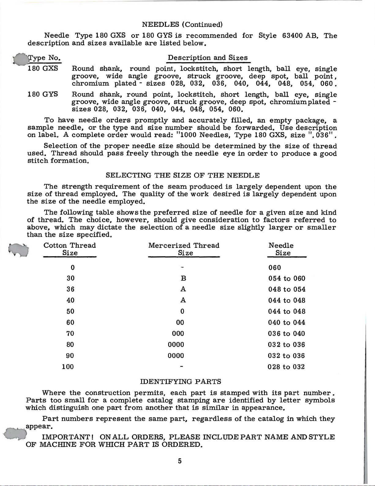
OILING
CAUTION!
the
reservoir
Fill
il
is
e
added
straight
in
the
Oil
The
in
the
wise
direction
NOTE:
It
long
period,
parts.
Run
machine
speed
must
main
at
maximum
reservoir
when
mineral
main
may
reservoir.
be
quantity
direction
The
top
twice
is
recommended
daily.
be
After
oiling,
slowly
operation
Oil
has
be
level
needle
is
oil
of a Saybolt
drained
of
oil
of
the
arrow
decreases
driven
lubricated
replace
for
can
then
been
filled
when
in
This
from
at
plug
yellow
drained
before
needle
is
main
supplied
(counterclockwise)
the
flow
grip-feed
that a new
by
head
several
be
expected
from
starting
screw
(B,
is
band
marked
viscosity
equivalent
reservoir
to
the
hook
of
oil.
mechanism
machine,
removing
cover
minutes
without
the
to
Fig.
in
yellow
of
to
is
or
the
as
no
to
distribute
main
reservoir
operate.
2A)
and
band
"LOW".
90
to
125
Union
by
Special
removing
controlled
increases
must
one
head
be
that
cover
further
damage.
before
check
marked
oil
"FULL".
Use a stainless
seconds
specification
plug
screw
by
dial
(E).
the
oil
flow
manually
has
and
hand
oil
to
been
oiling
oiling
the
oiled
out
various
level
at
100°
Turning
of
will
shipment
at gauge
Oil
water-white
Fahrenheit
No.
(D,
Fig.
the
and
in a clock-
at
(F,
Fig.
service
all
the
moving
be
required.
parts.
and
(C);
should
175.
2A) .
dial
2A)
for
Full
a
Fi
g.
2A
9
Page 10

(a)
presser
The
63400 B
TO
Remove
end
connecting
and
a v o i d c
main
stitch
covered
CHANGE
the
of
the
withdraw
feed
to
INSTRUCTIONS
adjusting
STITCH
snap
top-
hinge
hip p in g teeth
foot
dog
the
instructions
in
Catalog
ring
grip-
pin.
feed
while
required
pin
feed
(A,
This
dog
setting
LENGTH
from
No. 121
one
drive
Fig. 2 8)
is
to
of
the
or
the
the
length
for
AND
.
FOR
Style
M,
SET
MECHANICS
63400
with
THE
AB
the
additions
TOP-GRIP-FEED
are
the
as
same
follows:
as
for
Style
Loosen
(b)
a
(c)
Turn
wise
retighten
NOTE:
crank
equal
sides,
adjustment
screws
the
(C) a s r e
screws
Turn
(d)
forward
(e)
Replace
snap
NOTE:
the
the
ward
nut
left
hand
screw
to
its
extreme
nut
Be
link
lateral
so
there
be
{B,
top-grip-feed
qui
(B).
handwheel
end
the
ring.
It
may
top-grip-feed
top-grip-feed
position,
{A,
Fig.
thread).
(B)
counterclock-
position
(A).
sure
that
assembly
clearance
is
no
bind.
necessary,
Fig.
of
28)
rocker
r e d .
to
its
travel.
top-grip-feed
be
necessary
drive
drive
tighten
29) {it
the
top
(C)
on
Should
loosen
and
move
Retighten
position
arm
arm
screws
has
and
feed
has
both
arm
the
drive
to
{D),
so
{E).
top-grip-feed
connecting
loosen
presser
for
screws
alignment
foot
drive
hinge
(E,
Fig.
to
feed
Fig.
arm
pin
insert
dog
28
28)
is
{A)
the
at
(D)
and
and
its
at
the
secure
slightly
hinge
extreme
extreme
rotate
pin.
Hold
with
for-
At
this
{f)
With
Fig.
point
the
29
the
presser
operating
synchronized
the
set
29)
advance
required.
direction
feed
desired
{g)
presser
foot
main
screws
to
the
dogs.
Loosen
necessary
foot
feed
{F,
or
conditions.
Fig.
direction.
to
feed
dog.
holding
top-
grip-
retard
Snug-up
and
observe
Repeat
nut
move
{A,
to
dog
is
28)
raised
The
forward
Should
the
top-grip-feed
feed
drive
the
top-grip-feed
screws,
relationship
timing
Retighten
Fig.
set
the
set
at
presser
or
timing
shaft.
rotate
adjustment
screws
29)
and
stitch
10
its
maximum
slightly,
foot
rearward
be
necessary,
drive
While
handwheel
between
securely.
turn
length
length
rotate
feed
holding
drive
as
necessary
screw
of
dog
simultaneously
shaft
shaft
upper
{B)
the
of
travel.
handwheel
should
loosen
head
the
in
clockwise
top-grip-fee·
the
{D,
handwheel
head
{D)
operating
and
lower
to
obtain
in
be
with
two
Fig.
as
a
""""'"-..-
Page 11

TO
CHANGE
STITCH
LENGTH
AND
SET
THE
TOP-GRIP-FEED
(Continued)
comparable
lateral
before.
(h)
As a basic
dog
point
(E,
presser
presser
(G)
(H),
NOTE:
moving
the
( i) Sew
evenly.
can
( f)
clearance
left
to
to
point,
Fig.
which
position
Care
parts
presser
off
sample
Should
be
adjusted
and
(g)
to
setting,
right.
28)
which
foot
as
foot
feed
secures
as
of
foot.
for
the
main
on
The
both
the
feed
presser
last
stitch
sides
tooth
in-line-of-feed.
required.
dog,
the
required
must
the
of
material
the
will
be
presser
plies
allow
from
presser
and
taken
and
come
Retighten
left
retighten
to
foot
INDEPENDENTLY
this
adjustment.
length.
of
foot
of
the
This
forward,
to
foot
feed
assure
and
examine
out
uneven,
to
Recheck
top
feed
feed
top
can
screws
right,
dog
screws
that
satisfy
Retighten
crank
dog
should
and
bottom
be
accomplished
rearward
(E). A minute
can
be
to
the
(G).
that
no
the
needle
to
see
if
the
top
this
settings
nut
link
assembly
line
feeds
or
obtained
connecting
binding
centers
top
and
driven
condition.
covered
(A).
Recheck
up
with
should
by
loosening
lateral
adjustment
by
loosening
rod
grip
condition
the
bottom
grip-feed
Refer
in
paragraph
for
equal
as
described
the
main
match
tooth
screws
positioning
of
screws
feed
hinge
exists
needle
plies
in
hole
come
mechanism
toparagraphs
(h).
feed
of
the
the
of
out
11
Page 12

12
Page 13

The
parts
that
are
Use
Catalog
Reference
dicate
illustrated
used
on
numbers
they
are
on
Style
63400 AB,
No. 121 M
that
component
TOP
DRIVEN
pages
(Style
12
and
but
63400 B)
are
inside a bracket
parts
of a complete
GRIP-FEED
14,
and
not
used
described
on
for
all
on
MECHANISM AND
Style
63400 B.
parts
the picture
part
or
on
this
page
not
illustrated
plates
assembly.
MISCELLANEOUS
and
or
and
page
15
described
have
indented
PARTS
represent
in
this
descriptions,
the
parts
catalog.
Ref.
No.
1
2
3
4
5
6
7
8
9
10
11
12
13
14
15
16
17
18
19
20
21
22
23
24
25
6
7
28
29
30
31
32
33
34
35
36
37
38
39
40
41
42
43
44
45
46
47
48
49
50
51
52
53
54
55
56
7
~a
59
Part
No.
63494
29475
22894
22894
22894
63439
22651
63493 A
63439
22525 c
22894
22711
63439
22657
63979 A
63479
63479
22591
63439 R
63439
63479 A
22656
22519 c
51235
51235
63439
63439
22730
51236
51236
22768
51054
63439
53564
22652
63485
63439 E
56335
51235
22519 c
56341 E
56335 J
22738
51330
56334
36263-936
B
AZ
w
u
v
u
CD-3
v
J
X
E-24
666-244
W0-3
c
666-198
D
y
D-12
G
A
269
20
AE
AD
G
B
82
666-149
77
w
G
482
98
D-20
A
H
G
660-310
s
87 u
F
Description
Plug,
Mainshaft
Grip-
Bed
Grip-Feed
Screw,
Guard,
Screw,
Oil
Columbia
Grip-Feed
Felt
Grip-Feed
Screw,
Grip-Feed
Grip-
Grip-Feed
Screw,
Screw,
Washer,
GripNut,
Washer,
Feed
Screw,
Feed
Feed
Screw,
Adjusting
Feed
Screw,
Spacer,
Dowel
Collar,
Screw,
Bushin
Grip-Feed
Grip-Feed
Retaining Ring
Hin
Grip-Feed
Chain
Screw,
Grip-Feed
Hin
Presser
plastic,
Set
Screw------------------------------------------------------Spot
Screw----------------------------------------------------------
Feed
Set
Screw-------------------------------------------------------
Plug
Screw---------------------------------------------------------Set
Screw------------------------------------------------------for
for
for
Shield,
Fell
Wick,
for
Feed
for
for
Feed
for
feed
Crank
Ferrule
for
Crank
Crank
for
Link
Felt
for
for
Pin,
for
Screw----------------------------------------------------------
for grip-feed
g,
Washer--------------------------------------------------------Screw----------------------------------------------------------
ge P i
n-----------------------------------------------------------
Screw----------------------------------------------------------
Cutting Knife--------------------------------------------------
for
ge Pin-----------------------------------------------------------
Foot
for
arm-----------------------------------------------
and
Counterweight
Screw------------------------------------------------------
Driving
----------------------------------------------------------Driven
drive
drive
drive
for
Lining
Yarn----------------------------------
Drive
for
Drive
drive
Drive
Drive
Drive
grip-feed
grip-feed
for
grip-feed
Rocker
for
feed
Link
oil
Stud----------------------------------------------------Stud
feed
Screw,
Crank
Wick-------------------------------------------------------
feed
grip-feed
for gri
grip-feed
for
grip-feed
Rocker
Drive
Drive
grip-
Connecting Rod
Gear----------------------------------------------
Gear
shaft
guard------------------------------------------
shaft
shaft
drive
-----------------------------------------------------
drive
crank
-------------------------------------------------------shield-------------------------------------------------
crank
rocker
------------------------------------------------------
feed
(See
bracket----------------------------------------
shaft
Shaft
shaft
Shaft
shaft
head-------------------------------------------
Shaft
Head-------------------------------------------
Shaft
Shaft
Sleeve----------------------------------------mechanism
rocker
rocker
Arm-----------------------------------------------
stud----------------------------------------------
crank
Assembly-------------------------------------------
Cap-------------------------------------------------
stud
for
feed
Link
Pin--------------------------------------------
mechani
p-feed
rocker
mechanism
Arm
Arm------------------------------------------------
Connection------------------------------------------
connecting rod
Page
Assembly
----------------------------------------------
----------------------------------------------bushing-------------------------------------
Bushing,
Bushing,
-----------------------------------------------
stud------------------------------------------
crank
arm-------------------------------------------
mechanism
mechanism
Shaft
15)
right----------------------------------
bushing,
left-----------------------------------
support-------------------------------
arm--------------------------------------
arm
cap----------------------------------------
stud-----------------------------------
sm
arm shaft---------------------------------
support-------------------------------
-----------------------------------------
Hinge--------------------------------------
------------------------------------------
--------------------------------
left--------------------------------
------------------------------------
support------------------------------
support--------------------
support-----------------------------
hinge-----------~------------------
--------------as
-
------
Amt.
Req.
2
1
1
1
2
1
2
1
1
3
2
1
1
2
1
1
required
1
1
1
2
1
1
1
1
2
2
1
1
1
1
1
1
1
1
2
1
1
1
1
1
1
2
1
1
1
1
1
2
2
2
1
1
1
1
2
1
1
1
13
Page 14

1
------------
25
14
Page 15

PRESSER
FEET,
(WIDE
FEED
SEWING
DOOS AND
THROAT
COMBINATIONS)
PLATES
Ref.
No.
1
2
3
4
5
6
7
8
9
10
11
12
13
14
15
16
17
18
19
20
21
22
23
24
Part
No.
61405
61324
61324
61324
61324
63420
22738
61430
61430
63430
1594
61430
63430
61430
61430
56330
61420
22738
61430
61430
61430
1594
61430
61430
61430
61430
61430
AG
D-063
D-073
D-083
D-093
G
BP
BL
N
A
BK
R
BR
BT
F
CG
BP
BL
BM
A
BK
BN
BR
BT
BS
Description
Feed
Dog,
16
teeth
per
inch,
Throat
Throat
Throat
Throat
Presser
Presser
Plate, • 063
Plate,
Plate,
Plate, . 093
Foot
Assembly
Screw------------------------------------------Feed
Section
Presser
Feeding
Hinge
Presser
Feeding
Feed
Spring-------------------------------------------
Yielding
Screw
Feed
Presser
Feedinp
"BM'
Hinge
Presser
Feeding
"BN"
Feed
Spring-------------------------------------------
Yielding
Foot
Section,
Pin----------------------------------------
Foot
Section,
Section
Section
Foot
Assembly
-------------------------------------------
Section
Foot
Section,
------------------------------------------
Pin----------------------------------------
Foot
Section,
------------------------------------------
Section
Section
inch
. 073
inch
. 083
inch
inch
Guide,
Shank
left,
Bottom
right,
Guide,
----------------------------------
Guide,
Shank-------------------------------
left,
Bottom------------------------------
right,
Guide,
----------------------------------
marked
needle
needle
needle
needle
(without
left,
------------------------------
right,
(with
left,
right,
hole
hole
hole
hole
marked
(without
----------------------------(without
marked
16
marked 11B
16
teeth
16
teeth
marked
"BK"--------------
--------------------
--------------------
--------------------
--------------------
teeth)------------------
"B"
--------------
teeth)
teeth
per
teeth)
"C"
per
inch,
per
"c"
marked
marked
-------------
inch)----------
11
--------------
marked
inch,
marked
-------------
"L"
"N"
----
---
Amt.
Req.
1
1
1
1
1
1
4
1
1
1
1
1
1
1
1
1
1
4
1
1
1
1
1
1
1
1
1
25
26
27
28
29
30
31
32
33
34
35
36
37
38
39
40
41
42
43
44
45
46
47
48
61405
61424
63420
22738
61430
61430
63430
1594
61430
63430
61430
61430
56330
61420
22738
61430
61430
61430
1594
61430
61430
61430
61430
56330
AK
AK
F
B
CH
BL
p
A
CE
M
CJ
BT
F
CJ
B
CH
BL
CF
A
CE
CG
CJ
BT
F
(NARROW
Feed
Throat
Presser
Screw-------------------------------------------
Feed
Presser
Feeding
Hinge
Presser
Feeding
SEWING
Dog,
16
teeth
Plate,
Foot
Assembly
Section
Foot
Section,
Pin----------------------------------------
Foot
Section,
COMBINATIONS)
per
inch
---------------------------
. 073
inch
needle
(without
Guide,
Shank-------------------------------
Bottom
left,
marked
left
(without
-----------------------------
right,
(without
hole
"K"--------------------------------------------
Feed
Spring------------------------------------------Yielding
Presser
Screw-------------------------------------------
Feeding
Hinge
Presser
Feeding
Feed
Spring-------------------------------------------
Yielding
Section
Foot
Feed
Section
Presser
"D"--------------------------------------------
Pin----------------------------------------
marked
Section
Guide,
Section----------------------------------
Assembly
Guide,
Foot
Shank-------------------------------
Section,
Foot
Bottom
Section,
"E"
------------------------------------
Guide,
Section
right,
(with
left,
left,
right,
right,
----------------------------------
marked
16
marked
16
teeth
----------------------------16
teeth
marked
--------------------
teeth)------------------
"G"
--------------
teeth)
teeth
marked
teeth)
per
per
marked
"F"
-------------
per
inch)----------
"G"---------------
inch,
inch,
"F"
-------------
"M"
marked
-----
1
1
1
4
1
1
1
1
1
1
1
1
1
1
4
1
1
1
1
1
1
1
1
1
15
Page 16

WORLD'S
FINEST
QUALITY
*
INDUSTRIAL
SEWING
MACHINES
UNION
SPECIAL
maintains sales
and
facilities throughout the world. These offices
aid
you
in
the selection of the right sewing
equipment for your particular operation. Union
and
Special representatives
tory trained
promptly
tion, there
and
and
is
a Union Special Representative to
serve you. Check with
ATLANTA,
BOSTON,
CHICAGO,
DALLAS, TEXAS
LOS ANGELES, CAL.
NEW
PHILADELPHIA,
GA.
MASS.
YORK,
ILL.
N.
Y.
PA.
are
efficiently. Whatever your loca-
service men
able
to serve your needs
him
today.
MONTREAL, CANADA
TORONTO,
BRUSSELS, BELGIUM
LEICESTER,
LONDON,
PARIS, FRANCE
STUnGART,
service
will
are
fac-
CANADA
ENGLAND
ENGLAND
GERMANY
400
Representatives
MACHINE
N.
FRANKLIN
Industrial
and
cities
distributors
throughout
COMPANY
ST.,
CHICAGO,
In
the
all
Important
world.
ILL.
60610
 Loading...