

Page 1

INDUSTRIAL
SEWING
FINEST
STYLES
63400A
634
®
QUALITY
00B
MACH
INES
CLASS
CATALOG
S
TREAMLINED
No.
121
M
SECOND
EDITION
HI
GH S
PEED LOCKS
UNION SPECIAL
CHICAGO
63400
TIT
CH
MACHINE
S
CORPORATION
Page 2
Catalog
No.
INSTRUCTIONS
FOR
121
M
ADJUSTING
LIST
Streamlined
63400
Second
AND
OF
CLASS
Styles
A
OPERATING
PARTS
63400
Lockstitch
63400
Edition
B
®
1961
By
Union
Rights
Special
Reserved
Corporation
in
All
Countries
UNION SPECIAL CORPORATION
INDUSTRIAL
Printed
SEWING
CHICAGO
in
2
MACHINES
U.S.A.
August,
1981
Page 3
Each
plate
numbers
63400
a
on
A".
standard
UNION
the
machine.
have one
Special
machine,
SPECIAL
or
more
Style
a "Z"
machine
Style
letters
numbers
is
IDENTIFICATION
is
identified
numbers
suffixed
are
suffixed,
contain
to
OF
by a
classified
but
never
the
letter
the
Standard
MACHINES
Style
number which
as
standard
contain
"Z".
When
Style
is
stamped
and
special.
the
letter
only
number.Example:
"Z".
minor changes
into
Standard
Example:
"Style
the
Style
"Style
are
made
63400 AZ".
name
in
Styles
from
the
This
can
also
ence
to
tion
while
High
Speed
Drop
Feed,
dicator,
Oil
Control,
for
Take-up
Space
*63400 A
to
inch
plate,
guides.
63400 B
1
13/64
throat
and
of
machines
style
be
direction,
One
Right
guides.
number,
catalog
applied
seated
Streamlined
Rotary
Reservoir
Automatic
Lever
of
For
miscellaneous
needle
feed
For
miscellaneous
inch
plate,
applies
with
such
at
Hook,
and
Needle
bar
dog,
needle
feed
similar
in
that
specifically
discretion
as
the
machine.
Long
Horizontal
Enclosed
Head
Needle
Bar 11
travel.
stitches
bar
dog,
it
right,
Arm
Oiling,
Bar
plain
Type 183
per
plain
travel.
stitches
in
construction
contains
APPLICATION
to
to
some
left,
Operating
Lockstitch
Automatic
Driving
1/8
seaming
seaming
STYLES
Hook
Needle
Inches.
GXS
inch,
Type 180
per
front,
Shaft,
are
no
letters.
OF
the
Standard
Special
back,
direction
OF
MACHINES
Machines,
Push
Lubricating
Bearing
Link,
thread
Feed Timing on Lower Main
operations
or
183
size,
operations
GXS
inch,
thread
grouped
CATALOG
Styles
etc.,
of
One
Button
System, Head
Adjustable
on
GYS
needle.
needle
on medium and medium heavy
or
180
under a class
Example:
Styles
of
are
the
handwheel
Needle,
Stitch
light
type
GYS
size,
needle
"Class
of
machines
machines
given
Feed
and medium
Specify
needle.
from
Light,
Regulator,
Oil
Eccentric,
and
size,
type
in
is
Medium
Siphon,
presser
Specify
number which
63400".
as
listed
this
Class.
the
operator's
toward
Shaft,
weight
and
the
and Heavy
Stitch
Adjustable
Needle
Maximum
work, 1
foot,
attachments
weight
presser
size,
differs
herein.
Refer-
posi-
operator.
Duty,
Length
Bearings
throat
attachment
In-
Hook
Work
9/64
and
work,
foot,
It
*
DISCONTINUED -In
Each
needle
point,
denotes
and
or
listed
Type No.
180
180
183
183
the
Needle
183
GXS
GYS
GXS
GYS
length,
largest
size
GYS
is
below.
number
Type 180
most
has
both a type
groove,
diameter
recommended
Round
wide
sizes
Round
wide
080/032,
Round
groove,
plat
Round
groove,
028,
finish
represent
GXS
shank,
angle
075/029,
shank,
angle
shank,
ed -
shank,
080/032,
instances,
and
of
the
the
or
180
for
Style
round
groove,
round
groove,
090/036,
round
wide
angle
sizes
round
wide
angle
090/036,
component
NEEDLES
and
size
number. The
other
blade
complete
GYS
080/032,
025,
details.
measured
symbol.
is
reconnnended
63400
point,
struck
point,
struck
100/040, 110/044,
point,
groove,
point,
groove,
A.
Description
lockstitch,
groove,
090/036,
lockstitch,
groove,
lockstitch,
struck
075/029,
lockstitch,
struck
040,
parts
Their
080/032, 090/036,
044.
The
across
for
deep
100/040,
deep
groove,
groove,
can
be
ordered
type
size
number, stamped on
the
eye.
Style
description
and
Sizes
short
spot,
110/044, 125/049,
short
spot,
125/049,
extra
deep
extra
deep
number
Collectively,
63400
and
length,
ball
length,
chromium
140/054,
short
spot,
100/040,
short
spot,
for
customer
denotes
Band
point,
length,
length,
needle
the
sizes
ball
eye,
chromium
ball
eye,
plated -sizes
150/060.
ball
ball
point,
110/044.
ball
chromium
repair.
the
kind
the
needle
the
type
Type 183
available
single
plated
140/054,
single
eye,
chromium
eye, sin
plated -sizes
of
shank,
shank,
number
are
groove,
150/060.
groove,
075/029,
single
gle
GXS
-
3
Page 4
To
sample
on
label.
have
needle,
A
complete
needle
or
the
orders
type
order
NEEDLES
promptly
and
size
would
(Continued)
and
accurately
number
read: 111000
should
Needles,
filled,
be
forwarded.
Type
an
180
empty
Use
GXS,
package,
description
Size
080
a
/ 032'~
Selection
used.
stitch
SELECTING
size
of
above,
than
Thread
formation.
The
of
the
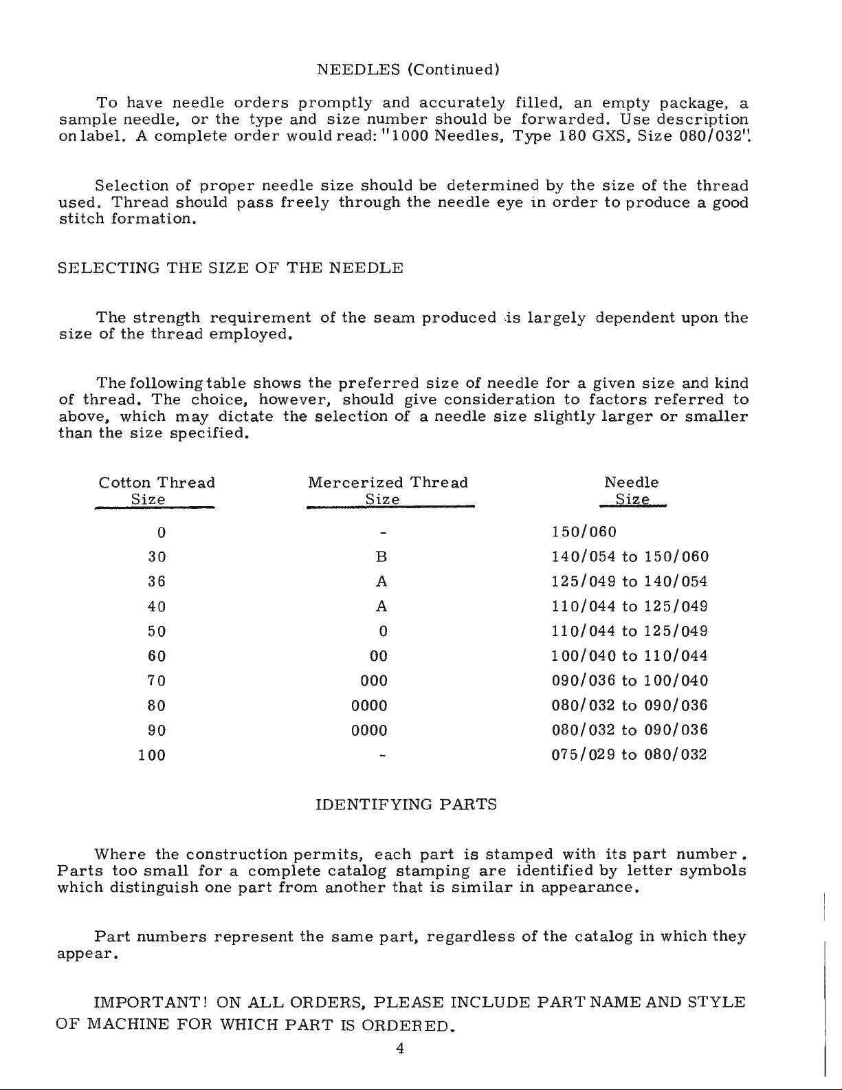
The
thread.
which
the
Cotton
strength
following
size
Size
of
should
THE
thread
The
may
specified.
Thread
0
30
36
proper
pass
SIZE
requirement
employed.
table
choice,
dictate
needle
freely
OF
THE
shows
however,
the
size
should
through
NEEDLE
of
the
seam
the
preferred
should
selection
Mercerized
Size
B
A
be
determined
the
needle
produced ·.is
size
of
give
consideration
of a needle
Thread
eye
needle
size
by
the
in
order
largely
for a given
to
factors
slightly
150/060
140/054
125/049
size
of
the
to
produce a good
dependent
size
referred
larger
Needle
Size
to
150/060
to
140/054
or
thread
upon
and
kind
smaller
the
to
Where
Parts
which
appear.
OF
too
distinguish
Part
IMPORTANT!
MACHINE
40
50
60
70
80
90
100
the
construction
small
numbers
FOR
permits,
for a complete
one
part
from
represent
ON
ALL
WHICH
the
ORDERS,
PART
A
0
00
000
0000
0000
IDENTIFYING
each
catalog
another
same
IS
stamping
that
part,
PLEASE
ORDERED.
PARTS
part
is
is
similar
regardless
INCLUDE
stamped
are
identified
in
of
110/044
110/044
100/
040
090/036
080/
032
080/
032
075/029
with
appearance.
the
PART
its
by
catalog
NAME
to
125/049
to
125/049
to
110/
to
100/040
to
090/
to
090/
to
080/032
part
letter
in
AND
044
036
036
number.
symbols
which
STYLE
they
4
Page 5
ILLUSTRATIONS
The
arrangement
Class
plate
sition.
discussed
found a listing
pieces
position
ordering
view
63400
Six
exploded
presents
Small
fit
required
Numbers
of
parts.
plate
carries
replacement
the
a
keyline
in
of
in
in
the
part
Always
of
view
sector
the
assembled
the
the
first
in
a
reference
ORDERING
this
parts.
plattes
of
views
parts
particular
the
use
catalog
cover
the
show
with
column
illustration.
the
OF
is
to
the
Standard
machine,
by a blackended
machine.
their
view
are
part
number
parts
On
part
being
reference
number
for
REPAIR
facilitate
being
the
page
numbers,
shown.
numbers
Reference
listed
each
part
PARTS
Styles
aligned
area
opposite
numbers
in
the
for
easy
descriptions
and
listed
as
exactly
only,
second
sale.
accurate
in
in
where
the
and
should
ordering
this
catalog.
their
illustration
and
merely
column. Each
the
the
never
assembled
parts
number
indicate
be
of
Each
po-
being
will
used
exploded
be
of
the
in
Sub-assemblies,
or a solid
can
be
furnished
description
20
21
22
23
catalog,
parts
in
tion.
in
only
UNION
iaries
scientific
durability
29126
61438
660-225
In
for
the
description,
At
this
book.
the
Success
SPECIAL
and
line
of
DD
B
88
those
no
specific
the
the
back
part
in
authorized
principles,
are
box
for
the
main
cases
various
of
This
number
the
Repair
assured.
which
on
repairs,
Feed
where a part
usage
machines
and,
the
will
is
operation
Parts
distributors.
are
the
picture
are
sub-assembly.
Driving
Feed
Drive
Needle
Set
will
if
necessary,
book
will
facilitate
known.
USE
of
as
furnished
and
are
sold
are
made
complete,
plate.
indicated
Example:
Eccentric
Eccentric
Bearing--------------------------------------
Screw-------------------------------------------
is
connnon
be
mentioned
not
the
the
be
found a numerical
locating
GENUINE
these
machines
by
They
with
utmost
or
Component
by
indenting
and
Connecting
Connecting
to
all
in
the
same,
difference
the
REPAIR
can
the
Union
are
designed
precision.
by
separate
parts
Rod----------------------
of
the
machines
description.
the
specific
will
index
illustration
PARTS
be
secured
Special
according
part,
of
their
Rod
Assembly------------
usage
be
shown
of
and
Corporation,
Maximum
are
in a bracket
sub-assemblies,
descriptions
covered
However, when
will
in
all
the
description
only
with
to
the
efficiency
by
be
the
parts
genuine
its
most
which
under
this
the
mentioned
illustra-
shown
when
subsid-
approved
and
the
1
1
1
1
TERMS
Pric
es
are
are
wise
forwarded
directed.
strictly
f.o.b.
A
charge
net
shipping
is
cash
point.
made
and
to
subject
Parcel
cover
the
to
change
Post
postage
shipments
and
5
without
are
insurance.
notice.
insured
All
shipments
unless
other-
Page 6

CAUTION!
on
bed
Before
machine
casting,
leaving
and
When
lift
gently.
accessories
factory,
unpacking,
each
have
been
DO
NOT
UNION
removed
lift
machine
SPECIAL
from
INSTALLING
out
of
machine
the
packing
box
is
box,
by
sewed
the
placing
off,
following
one
hand
inspected
steps
on
handwheel.
and
carefully
should
be
followed:
Using
packed.
both
After
hands
the
PHEPAHATION
A
bag
of
hinge
Insert
STANDARD
Included
machine
positioning
setting
TABLE
Lockstitch
of
the
MACHINE
On a suitable
rear
(Fig.
spring
(21393
Place
plate
edge
underside
Tip
should
assembly
studs,
hinge
ACCESSORIES
also
mounting
spring
up
the
TOPS
machine
MOUNTING
1 ).
(63474
R)
to
outside
sewing
and
of
the
machine
be
taken
OF
and
two
studs
with
and
machine.
machines
mounting
tableboard,
Insert
A)
over
head
the
board
back
up
by
MACHINE
parts,
screws
in
holes
each
frame,
screw,
are
frame.
FRAME
the
countersunk
right
front
of
in
the
frame
sides,
and
against
the
cone
FOH
INSTALLATION
consisting
for
holding
provided
machine
one
hinge
pan
frame
tighten
is a box
oil
drain
four
isolator
installed
INSTALLATION
place
machine
pad;
section,
mountin
rap
Jocking nuts
rest
pin,
bearings,
of
miscellaneous
for
jar
in
table
wood
insert
as
the
retaining
and
assemble
but
one
frame
thread
them
in
rear
of
STANDARD
and
its
and
tops,
throu
head
and
after
plate
securely.
not
clamp
clips,
prepared
and
the
bind,
pads
mounting frame
screw
round
shown,
g,
must
eyelet,
attachments
of
cloth
ACCESSORIES--containing
spring,
and
(21393
gh
left
wood
screw
snug up
being sure
smartly
knee
press
one
with
hinge
nuts
one
plate.
one
machine
cut-out,
N)
pad
and
lightly.
there
upward
assembly
eyelet
to
Assemble
knee
in
and
tighten
is
attaching
the
bed
plate,
the
lifter
pin,
that
machine
securely.
securely.
as
shown.
assembly
the
rest
so
the
tighten
about 1 /16
with a hammer
screw,
is
upper
one
These
bed
cut-out
Assemble
inch
to
All
packed
bobbin
plate
clearance
one
extra
with
each
frame
eyelet
winder
and
its
is
FLUSH
the
play
rubber
are
essential
hinge
bed
the
retaining
between
of
the
parts
with
Assemble
insure a good
end
bobbin,
machine.
(A,
Fig.
assembly,
pad,
with
the
lugs
posit10ning
the
grip
cross
when
to
plate
cloth
on
shaft
two
2).
the
bed
top
the
the
;:
166
3 0
2l393N_/
~
6
60-168
6
-
63476C
61477
Fig.
1
Page 7

INSTALLING
(Continued)
MACHINE
Before
adjusted.
parts
do
the
presser
BOBBIN
The
the
elongated
needed.
wind
under
BELTS
bobbin
sewing
the
OPERATOR'S
These
MOUNTING
the
machine
The
not
WINDER
The
bobbin.
left
interfere
bar
raises
winder
machine
attaching
pulley
machines
FRAME
is
stop
belt
holes,
of
Regulation
INSTRUCTIONS.
are
put
screw
with
moving
approximately
should
the
be
and
will
which
winder,
and
equipped
INSTALLATION
into
production,
(22597
secured
F)
parts
5/16
bear
against
allow
the
when
operation
to
use
should
within
inch.
to
the
mechanism
in
operation,
of
either
(Continued)
the
bell
be
set
the
head.
table
top
the
belt
the
bobbin
#1
"Vee"
crank
so
that
This
so
that
when
to
be
should
winder
or
the
may
its
in
operation.
moved
exert
round
(21665
maximum
be
pulley
closer
only
is
described
belts.
J)
done
enough
of
by
will
to
the
lift
setting
be
The
or
under
knee
of
the
the
located
base
of
farther
pressure
"Winding
lifter
presser
stop
directly
the
away
against
rod
bar
screw
in
winder
from
the
the
should
and
so
front
has
belt
belt
Bobbin",
be
its
that
of
two
as
to
7
Fig.
2
Page 8

LUBRICATION
CAUTION!
reservoir
Lubricate
slowly
can
RECOMMENDED
then
for
be
Oil
must
be
machine
several
expected
Us9 a stainless
at
100
Fahrenheit
No.
175.
Fill
main
is
at
maximum
needle
It
is
period,
needle
oiling
CAUTION!
control.
manual
dial
180
oil
should
is
in
recommended
be
bar
will
The
Siling
to
level
yellow
lubricated
link,
be
required.
The
oil
of
expose
be
introduced
mid-day.
has
filled
thoroughly,
minutes
without
OIL
water-white
in
the
reservoir
when
band
that a new
as
take-up
machine
control
the
head
the
manual
been
before
drained
starting
to
distribute
damage.
straight
main
reservoir.
at
needle
marked
follows:
and
its
lever
is
dial
(D,
mechanism
oiling
into
the
in
plug
screw
is
in
II
low".
machine,
Remove
and
provided
Fig.
2}
be
port.
oiling
from
to
the
operate.
accordance
the
oil
mineral
oil
This
(B,
yellow
band
or
onethathas
the
end
needle
with
is
shown
desired,
In
the
port
twice
main
to
with
the
various
reservoir
instructions
ofaSaybolt
is
equivalent
Fig.
2}
and
marked
"full".
been
cover
bar.
automatic
in
the
remove
manual
and
Replace
or
automatic
locking
oiling
daily -preferably
before
parts.
viscosity
to
Union
check
oil
Oil
out
of
directly
end
cover
manual
oiling
screw
position,
which
Full
of
Special
level
should
service
oil
the
as
head
position,
(G,
five
at
shipment
follow,
speed
90
to
125
specification
at
gauge
be
added
for
an
bearings
no
further
mechanism
and
Fig.
2}
or
six
starting
and
the
and
run
operation
seconds
(C};
oil
when
extended
of
the
hand
oil
should
and
turn
drops
time
of
and
Oil
may
OIL GAUGE
The
oil
an
adjustment
1.
2.
Place
Remove
the
machine}.
3.
Oil
should
bottom
4.
Loosen
5.
gauge
Tighten
needle
be
gauge
become
machine
the
be
edge
the
lock
Fig.
drained
is
set
reservoir
added
of
the
lock
nut
rests
nut
and
3
from
at
the
main
factory
necessary,
upright
or
on a level
plug
screw
removed
hole.
on
the
calibrating
on
the
yellow
replace
reservoir
the
so
band
plug
screw.
The
with
touching
by
to
show
the
following
table
(located
that
or
below
the
screw,
marked
Lubrication
is
automatically
shaft
into
(D,
the
shaft
distributing
bottom
cover
Should
cover,
it
distributing
can
be
done
right
end
low
point
or
slightly
it.
removing
proper
steps
should
bench.
the
oil
level
and
turn
"FULL"
ofthe
Fig.
3},
at
the
plate
(B)
it
become
is
imperative
plate
by
ofthe
reservoir
of
the
plug
screw
oil
level
be
followed:
handwheel
is
approximately
the
screw
on
gauge
mechanism
accomplished
which
is
sprocket
(A,
Fig.
3}
by
means
necessary
that
(A)
be
checked
removing
the
andlooking
oil
distributing
below
the
center
(F,
in
the
and
near
left
(C,
below
through
tubular.
end
which
of
to
remove
the
adjustment
very
large
Fig.
reservoir.
the
1/ 8 inch
or
right
Fig.
2).
the
the
Oil
by
means
is
secured
two
carefully.
plug
through
plate
of
shaft
2).
bottom
below
so
cloth
feed
is
introduced
of
screws
the
reservoir
of
screw
the
must
(D}
Should
of
that
plate
driving
an
to
(C}.
the
This
at
hole.
be
even
and
just
the
the
the
oil
the
oil
the
8
Page 9
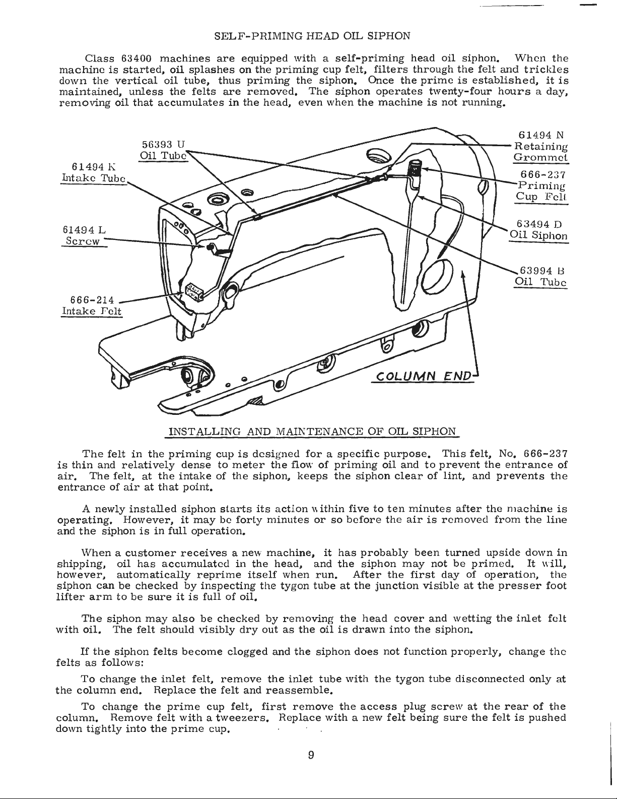
SELF-PRIMING
HEAD
OIL
SIPHON
Class
machine
down
maintained,
removing
61494
Intake
61494
Screw-----!.
is
the
K
Tube
L
63400
started,
vertical
unless
oil
that
machines
oil
splashes
oil
tube,
the
felts
accumulates
are
thus
are
in
equipped
on
the
priming
removed.
the
head,
with a self-priming
priming
the
The
even
cup
felt,
siphon.
siphon
when
filters
Once
the
head
the
operates
machine
r----~~---
oil
through
prime
twenty-four
is
not
siphon.
the
felt
is
established,
running.
When
and
hours a day,
61494
Retaining
Grommet
666-237
Priming
Cup
63494
Oil
63994
Oil
the
trickles
it
F'cll.
D
Siphon
Tube
is
N
13
The
felt
is
thin
and
air.
entrance
operating.
and
shipping,
however,
siphon
lifter
with
felts
the
column.
down
The
of
A
newly
the
siphon
When a customer
can
arm
The
siphon
oil.
If
the
as
follows:
To
change
column
To
change
Remove
tightly
INSTALLING
in
the
priming
relatively
felt,
at
the
air
at
that
installed
However,
is
in
full
oil
has
accumulated
automatically
be
checked
to
be
sure
may
The
felt
should
siphon
end.
the
into
felts
inlet
Replace
the
prime
felt
the
cup
is
dense
intake
point.
siphon
it
receives a new
by
it
also
become
with a tweezers.
prime
to
of
starts
may
be
operation.
reprime
inspecting
is
full
of
be
checked
visibly
clogged
felt,
remove
the
felt
cup
cup.
meter
the
forty
in
oil.
dry
felt,
AND
designed
the
siphon,
its
minutes
machine,
the
head,
itself
the tyg
by
out
and
the
and
reassemble.
first
MAINTENANCE
for a specific
flow
of
priming
keeps
action
when
on
removing the
as
the
the
inlet
remove
Replace
the
within
or
and
run.
tube
siphon
five
so
before
it
has
the
at
oil
is
tube
with
the
with a new
OF
siphon
to
probably
siphon
After
the
junction
head
drawn
does
the
access
OIL
SIPHON
purpose.
oil
and
clear
ten
minutes
the
air
been
may
the
first
cover
into
the
not
function
tygon
plug
felt
being
This
to
prevent
of
lint,
is
removed
turned
not
day
visible
and
siphon.
tube
screw
sure
felt,
No.
the
and
prevents
after
be
wetting
properly,
disconnected
the
upside
primed.
of
operation,
at
the
at
the
the
from
presser
the
rear
felt
666-237
entrance
machine
the
down
It
inlet
change
only
of
is
pushed
of
the
is
line
in
will,
the
foot
felt
the
at
the
9
Page 10

THREAD
INSTRUCTIONS
FOR
OPERATORS
While
of
the
hook
the
direction
of
each
hand.
unwind,
Fig.
WINDING
Thread
from
down
post.
up
a
wardly
to
few
the
between
Press
the
turns
on
contact
position.
will
be
rotated
automatic
pulley.
varied
The
by
the
direction
rotation
of
twist,
Turn
it
is a
left
4
THE
supply
stop,
BOBBIN
the
the
an
wind
bobbin
down
tension
empty
in a clockwise
hand
with
When
lever
machine
the
and
throw-out
extent
regulating
of
favors
grasp a short
the
thread
twist,
REMOVING
direction
the
latch
hook.
the
be
winder
through
discs,
bobbin
the
end
(D)
belt,
machine
filled
until
member,
to
which
the
screw
the
twist
the
use
away
if
not,
it
To
remove
until
left
hand,
(A,
Fig.
Opening
latch
is
removed.
by
the
and
on
the
of
thread
direction,
until
pulley
and
is
operated,
the
which
the
bobbin
(C).
in
the
of a left
length
from
is a right
THE
the
the
reach
4),
the
latch
closed,
leading
eyelet
under
winder
around
and
press
is
is
locked
thread
disengages
is
filled
bobbin
twist
of
thread
you
with
twist.
BOBBIN
bobbin
needle
under
and
pull
retains
the
the
thread
(A,
Fig.
the
tension
shaft
the
bobbin
down-
moved
in
the
bobbin
engages
can
thread
thread
your
CASE
case,
reaches
the
the
bobbin
5),
(B)
into
that
the
the
be
1s
immaterial,
in
the
between
right
turn
its
table,
bobbin
the
bobbin
is
released
needle.
thumb
hand.
handwheel
highest
open
case
in
out
the
the
direction
To
determine
and
forefinger
If
the
in
operating
position.
the
bobbin
of
the
case.
and
can
strands
Using
case
sewing
When
readily
The
base,
screw
and
(E)
unevenly
The
operator
replace
can
be
tension
can
so
may
purpose
of a full
it
with
rewound
be
that
be
Fig.
post
shifted
any
readily
of
the
while
6
bracket
tendency
the
bobbin
bobbin
full
one,
the
is
mounted
fromleftto
corrected.
winder
at
all
and
machine
THREADING
forefinger
(A,
and
thread
right
of
the
times.
begin
is
The
Fig.
The
forefinger
on
the
by
bobbin
is
to
assure
When
to
wind
sewing.
bobbin
6).
bobbin
coming
10
winder
loosening
to
wind
an
the
bobbin
the
empty
THE
BOBBIN
case
and
second
itself
of
the
off
should
should
one
finger
right
the
in
the
machine
immediately.
CASE
beheld
of
be
held
hand
bottom
Fig.
5
between
the
between
(B,
Fig.
of
the
is
used
Bobbins
the
LEFT
the
bobbin.
up,
thumb,
hand
thumb
6)
with
Page 11

INSTRUCTIONS
FOR
OPERA
TORS
(Continued)
THREADING
Place
and
forefinger
bobbin
(C)
on
is
pulled
as
it
facing
The
(A,
Fig.
inserted
the
accumulated
case
case.
\
Fig.
will
the
the
when
go
handwheel.
cross
8),
as
(A,
Note
7
with
far
THE
bobbin
of
the
Fig.
looking
the
hole
is
to
up
as
lint
BOBBIN
in
right
7)
the
direction
counterclockwise.
RE
and
latch
the
C
part
and
INSERTING
spot ( sometimes
in
show
it
from
CASE ( Continued)
the
bobbin
hand,
under
at
the
bobbin
PLACING
Have
one
should
table
way
bobbin
Insert
Tighten
the
needle
the
will
go,
needle
case.
draw
the
tension
of
the
THE
the
needle
half
inches
be
and
through
into
the
case
THE
the
needle
set
screw
bar,
operator
and
to
hole
In
one
the
bobbin
spring
rotation
case
BOBBIN
bar
opened
the
sewing
snapped
NEEDLE
called
about
when
provide a means
so
the
of
from
of
into
securely.
needle
the
at
its
thread
with
the
opening
hook.
into
the
scarf)
1/ 4 inch
the
will
continuous
thread
(B)
the
CASE
highest
position.
needle
toward
needle
and
bobbin
back.
to
left
in
The
from
seat
through
hang
hand,
the
latch
bar
for
properly.
motion,
into
self
as
the
The
bobbin
position,
free.
and
table,
should
as
the
right,
the
end
has
been
cleaning
the
threading
end
The
by
it
should
then
far
with
the
diagonal
of
the
should
allow
reaching
about
bobbin
be
be
A
thumb
slot
eyelet
thread
rotate
two
case
under
placed
released
in
THREADING
Threading
thread
from
PREPARATION
the
highest
it
foot.
the
in
passes.
left
With
handwheel
through
bobbin
the
your
position.
Fig.
eyelet
to
the
9
case
THE
diagram
right.
FOR
left
in
needle
B
and
for
this
NEEDLE
Please
SEWING
hand,
operating
Pull
hole
TENSIONS
thread
sewed.
tensions
BOBBIN
screw
tension
bobbin
adjustment
(Fig.
note
hold
direction
up
the
in
A
perfect
The
(A,
suspended
2)
shows
that
the
end
needle
the
throat
are
locked
A
stitch
on
both
THREAD
tension
Fig.
on
the
check.
the
of
until
thread
stitch
threads.
on
9)
spring
by
the
places
needle
the
needle
the
needle
and
plate.
is
one
together
of
this
TENSION
the
bobbin
which
is
correct
the
bobbin
where
thread
thread,
the
Draw
in
which
in
kind
case
regulates
thread.
passes
moves
bobbin
both
the
the
center
is
is
when
the
needle
through
leaving
down
thread
threads
needle
of
secured
applied
tension
it
is
just
The
it
and
will
under
thread
the
by
by
spring
sufficient
thread
Fig.
the
needle
slack,
up
material
regulating
means
should
and
again
come
the
and
(B).
8
eye
turn
to
its
up
with
presser
bobbin
being
the
of a set
The
to
hold
not
be
11
Page 12

INSTRUCTIONS
FOR
OPERA
TORS
(Continued)
BOBBIN
Remove
clockwise
When
any
NEEDLE
The
(H,
THREAD
the
changes
THREAD
needle
Fig.
2).
the
direction
bobbin
as
Turning
counterclockwise
its
raised
scrap
TO
CHANGE
Press
in
operating
feed
direction
stitch
position,
material.
plunger
direction
eccentric.
to
increase
length.
THE
TENSION
bobbin
to
thread
varying
TENSION
thread
the
decreases
but
STITCH
(J,
Fig.
until
Continuing
the
case
apply
tension
the
tension
nut
is
generally
LENGTH
2)
stitch
(Continued)
from
more
needle
is
is
its
tension
correct,
thread
varied
in a clockwise
it.
This
should
done
in
firmly.
stitch
to
regulating
hold
the
length
holder
or
tension
by
not
while
While
plunger
and
in
and
turn
set
counterclockwise
it
rarely
turning
direction
be
the
holding
finger
in,
opposite
becomes
will
usually
the
increases
done
when
machine
plunger
is
felt
turn
direction
screw
to
release
necessary
attain a good
tension
the
the
presser
is
sewing
in,
turn
to
drop
handwheel
to
in
spring
tension.
to
regulating
tension,
foot
on a piece
handwheel
into
the
in
operating
decrease
in
make
stitch.
nut
while
is
in
of
slot
of
the
a
Stitch
dial
(K,
and
Fig.
2).
PRESSURE
The
presser
make
the
in
the
presser
clockwise
decreases
lengths
are
viewed
ON
work
foot,
direction.
the
pressure.
are
MA
spring
feed
turn
indicated
through
TE
RIAL
uniformly.
presser
Turning
should
by
graduations
the
window
exert
To
increase
spring
the
regulator
only
enough
regulator
on
the
indicator
in
the
belt
guard
pressure
the
pressure
(A,
Fig.
counterclockwise
to
on
10)
Fig.
10
12
Page 13

INSTRUCTIONS
FOR
MECHANICS
SETTING
The
at
the
factory.
plate
Fig.
seat
11
The
63400
of
180
marks
the
GYS,
A,
needle
on
THE
lower
NEEDLE
needle
The
distance
is 2 1/ 4 inches.
The
needle
upper
or
lines
183 GYS,
The
180 GXS
When
line
(B,
should
(A).
To
the
bar
move
its
illustration
using
bar
is
accomplished
the
bar
lowest
extra
on
is
the
(Fig.
used.
BAR
bar
four
bar
to
two
or
the
Fig.
be
EVEN
change
is
at
bar
position,
short
Style
TO
HEIGHT
bushing,
from
lines
height
are
used
which
lower
180 GYS,
needle
11)
(of
with
the
position
its
lowest
to
the
11)
shows
length
63400
in
the
same
the
one
the
bottom
engraved
and
are
with
are
lines
the
recommended
are
which
bar
is
the
pair
the
lower
position.
proper
tighten
the
proper
needle.
B,
using
manner,
to
which
of
on
the
referred
extra
used
are
at
its
selected)
edge
of
the
needle
Then,
timing
screw
Type
short
except
the
needle
bushing
needle
short
with
to
for
the
(A,
bar
as
TIMING
length
Style
short
recommended
lowest
position,
dependent
of
the
lower
bar,
loosen
line.
Keeping
securely.
setting
183 GXS
length
of
or
needle,
that
the
the
bar
Fig.
are
needle
63400
length
for
upon
needle
turn
the
the
clamp
the
needle
183 GYS.
Type
lower
is
timed,
11)
to
used
LINES.
Type
A.
needle
Style
the
upper
the
needle
bar
handwheel
screw
needle
bar
bar
The
180 GXS
pair
the
in
The
183
63400
bushing
(C)
on
of
is
set
throat
setting
two
GXS
Type
B.
timing
used,
until
and
link
at
Style
setting
or
timing
TIMING
pin
in
two
finger
in
the
in
such a position
needle.
the
needle
to
turn
the
low
used
edge
THE
Tip
the
the
screws
(A,
hook
Turn
the
er
in
setting
of
the
timing
Turn
the
needle
. 003
the
Then,
with
inch
setting
to • 005
hook
tighten
the
needle,
below
of
in
the
Adjust
until
case
inch
case
the
finger
holder
clearance
recess
HOOK
machine
table
and
Fig.
and
top.
swing
12).
hold
as
the
handwheel
bar
is
at
handwheel
mark ( of
the
needle
the
hook
and
as
close
inch
this
between
position,
the
two
at
the
bottom
needle
the
bobbin
recess
recess
between
(Fig.
back
Insert
out
Loosen
the
to
its
until
needle
bar
bushing
on
the
remaining
which
of
bar
case
is
and
12).
so
that
a new
the
the
hook
prevent
in
operating
lowest
the
the
pair
bar
shaft
to
the
the
tighten
time,
the
hook
bushing
holder
at
the
tighten
the
outside
it
rests
needle.
bobbin
case
three
and
bobbin
interference
position
needle
is
selected)
is
even
(A).
until
the
needle
needle
the
screws
the
top
point.
in
relation
positioning
top.
Place
the
finger
edge
on
Loosen
positioning
set
screws
case
direction
and
ascending
(Fig.
with
the
point
as
possible
and
the
set
screw
securely
of
the
If
this
to
the
attaching
of
projection
the
rest
the
(B)
holder
with
the
until
continue
and
11)
lower
of
the
without
point
of
opposite
and
eye
of
condition
the
throat
finger
projection
hook
the
recheck
the
needle
by
turning
screws
and
is
even
deflecting
hook
the
is
hook
the
should
does
plate
not
seat
the
on
the
finger
securely,
the
inside
Fig.
with
12
the
center
it. A spacing
satisfactory.
point
timing
exist,
(Fig.
bobbin
of
be
recheck
case
into
securely.
the
about
11).
the
allowing
edge
of
of
of
With
hook
1/64
the
holder
bobbin
1/32
bobbin
13
Page 14
INSTRUCTIONS
FOR
MECHANICS
(Continued)
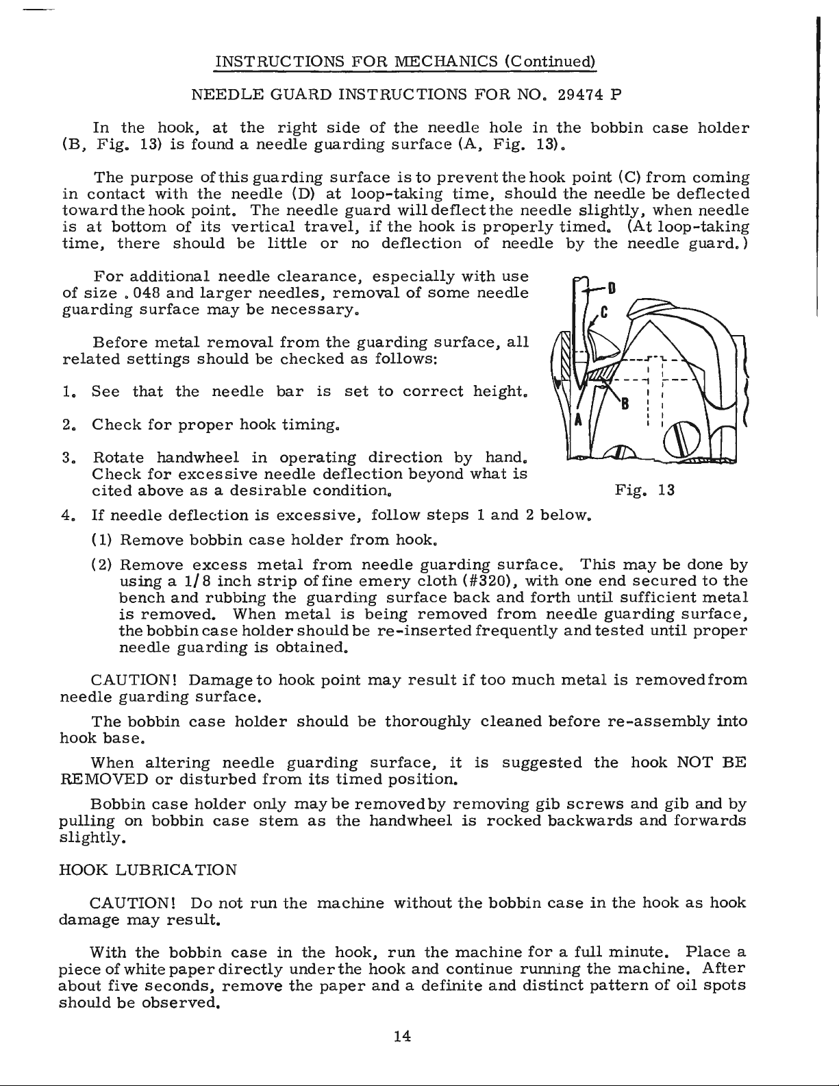
In
(B,
Fig.
The
in
contact
toward
is
at
bottom
time,
there
For
of
size . 048
guarding
Before
related
1.
See
2.
Check
3.
Rotate
Check
cited
the
hook,
13)
is
purpose
with
the
hook
of
should
additional
and
surface
metal
settings
that
the
for
handwheel
for
above
NEEDLE
at
GUARD
the
found a needle
of
this
guarding
the
needle
point.
its
The
vertical
be
little
needle
larger
may
needles,
be
necessary.
removal
should
be
needle
proper
hook
in
excessive
needle
as a desirable
INSTRUCTIONS
right
side
guarding
surface
(D)
at
needle
travel,
or
clearance,
removal
from
the
checked
bar
is
timing.
operating
deflection
condition.
of
the
surface
is
loop-taking
guard
no
will
if
the
deflection
especially
of
guarding
as
follows:
set
to
correct
direction
beyond
needle
to
prevent
deflect
hook
some
surface,
FOR
(A,
time,
is
properly
of
with
needle
height.
by
what
NO.
hole
Fig.
the
should
the
needle
use
all
hand.
is
29474
in
the
13).
hook
needle
timed.
bobbin
point
the
needle
slightly,
by
the
P
(C)
(At
needle
Fig.
case
from
be
when
holder
coming
deflected
needle
loop-taking
guard.)
13
4.
If
needle
(1)
Remove
(
2)
Remove
using a 1/8
bench
is
the
needle
CAUTION!
needle
hook
guarding
The
base.
bobbin
When
REMOVED
Bobbin
pulling
on
slightly.
HOOK
LUBRICATION
CAUTION!
damage
may
deflection
bobbin
excess
and
removed.
bobbin
guarding
Damage
surface.
case
altering
or
disturbed
case
holder
bobbin
Do
res
ult.
inch
rubbing
When
case
holder
holder
needle
case
not
is
excessive,
case
metal
strip
the
metal
is
obtained.
to
hook
from
only
stem
run
the
holder
from
of
fine
guarding
is
should
point
should
guarding
its
timed
may
be
as
the
machine
follow
from
hook.
needle
emery
surface
being
be
re-inserted
may
be
thoroughly
surface,
position.
removed
handwheel
without
steps 1 and 2 below.
guarding
cloth
back
removed
surface.
(#320),
and
from
with
forth
frequently
result
if
too
much
cleaned
it
is
suggested
by
removing
is
rocked
the
bobbin
gib
This
one
end
until
needle
metal
before
and
guarding
tested
is
re-assembly
the
screws
backwards
case
in
the
may
be
secured
sufficient
surface,
until
removed
hook
and
and
NOT
gib
forwards
hook
done
to
metal
proper
from
into
and
as
hook
by
the
BE
by
With
piece
about
should
of
white
five
be
the
bobbin
paper
seconds,
observed.
case
directly
remove
in
under
the
the
hook,
the
paper
run
the
machine
hook
and
continue
and a definite
14
and
for a full
running
distinct
minute.
the
machine.
pattern
of
Place
oil
a
After
spots
Page 15

INSTRUCTIONS
FOR
MECHANICS
(Continued)
should
lower
the
head
be
it.
turned
Make
of
the
Fig.
either
sure
that
regulating
14
clockwise,
the
bottom
screw.
of
to
t,he
raise
shank
HOOK
required,
ing
front
cloth
of
the
change
machine
minute
desired
FEED
feed
position
directly
screw
slightly,
the
feed
of
the
LUBRICATION
Should
more
turn
shaft
cf
the
plate
(E,
machine
surface,
Fig.
change
in
the
should
before
oil
flow.
DOG
In
clog,
HEIGHT
regulating
it
should
and
the
against
The
(A,
feed
Fig.
and
dog,
feed
or
dog
(Continued)
or
less
the
oil
control
2),
located
just
below
in
the
required.
hook
be
oil
run
flow,
about
checking
the
height
be
at
its
presser
foot
it.
dog
holder
14)
should
regulating
attaching
be
screw
counterclockwise
holder
rests
oil
be
adjust-
on
the
the
direction
After
the
one
for
the
of
the
highest
resting
loosened
(B)
against
a
to
A
Feed
should
plate
16
or
depth
suggested
dogs
having
show
at
highest
less
of a full
Fig.
about
point
teeth
tooth
16
initial
22
or
3 / 64
of
per
above
setting
more
inch
travel.
inch
be
above
should
the
The
is
teeth
Those
throat
feed
tilted
down
by
1 o o s e n i n g
screws
Loos
dog
screws
spa
c e
dog,
PRESSER
The
so
that
(B).
against
and
relocating
crank
the
proper
accomplished.
screw
as
per
the
show
as
required
(A
holding
the
front
presser
it
This
the
(C).
in
place.
follows:
inch
throat
having
the
plate.
dog
can
up
or
and
C).
en
feed
(
D)
t o
feed
to
BAR
CONNECTION
is
about
is
accomplished
rest
the
By
turning
setting
Tighten
back
bar
1/
pin,
stop
or
sideways
connection
16
inch
by
loosening
screw
the
stop
of
the
the
lock
Fig.
(A,
below
tipping
the
(B)
screw
presser
nut
in
Fig.
the
lock
on
(A)
15
the
16)
presser
the
nut
the
lifter
to
the
bar
to
throat
should
bar
plate.
be
guide
machine
(A,
Fig.
lever
right
or
connection
lock
the
set
back
15),
bell
left,
is
stop
15
Page 16

INSTRUCTIONS
FOR
MECHANICS
(Continued)
PRESSER
When
directly
is
set
properly
the
top
To
loosen
plate.
the
pressure
PRESSER
presser
presser
follows:
1.
2.
3.
Set
needle
The
To
Remove
Insert
Loosen
the
BAR
locating
against
of
the
obtain
set
the
enters
to
BAR
presser
feet.
bar
adapt
Presser
screw
GUIDE
the
when
throat
this
screw
the
is
presser
the
(C).
guide
the
presser
bar
However,
adaptable
the
machine
set
screw
as a handle.
the
presser
throat
there
plate
setting,
Tap
to
the
middle
No.
foot
foot
plate
is
a 4 3 / 4
(Fig.
remove
on
4 3 / 4
of
its
foot
by
63457 J is
should
• .
to
receive
and
presser
screw
in
the
presser
bar
with
16)
presser
inch
slot
turning
feet
in
the
guide
the
inch
the
dimension,
and
presser
presser
(B,
feed
space
pressure
foot
retighten
the
regulator
designed
of a different
foot
screw
bar
guide
Fig.
dog
in
between
to
insure
center
primarily
feet
of
from
bar
so
and
16),
the
its
lowest
the
from
screw
the
its
the
( C)
(A,
Fig.
to
manufacture
other
it
rotate
manufacture,
presser
screws
presser
position.
thread
presser
being
foot
in
10)
receive
in
presser
take-up
down
by
turning
guide.
clockwise.
be
bar.
from
bar
foot
must
The
wire
spring
on
the
it
Now,
Union
required,
proceed
right
180°
rest
guide
and
(F)
and
throat
so
that
apply
Special
the
as
to
left.
using
4.
Attach
the
needle.
5.
Check
CAUTION!
the
presser
Test
should
snap
it
located
assembly,
loosen
socket ( C).
wise
upper
tension
spring
proceed
desired
the
adjustment
the
be
when
require
under
tension
until
stop
post
again
tension
tension
slotted
presser
the
presser
guide
check
enough
spring
adjusting,
and
remove
Turn
the
(E)
(D)
touches
further
post
set
of
the
end
foot
to
bar
When
spring
arm
post
check
and
in a clockwise
is
presser
height
tension
is
depressed
loosen
and
set
the
tension
spring
has
in
the
obtained.
screw
check
of
the
must
TENSION
tension
to
tension
screw
no
the
same
(B)
spring
tension
the
bar
and
guide
assure a good
to
tension
upper
should
for
feet
other
be
checked
ASSEMBLY
(A,
Fig.
and
released.
set
screw
the
right
assembly.
(B)
in
post
(D)
moves
on
direction
stop
direction
When
be
tension
post
correct
counterclock-
away
correctly
drawn
can
align
than
and
17).
returning
in
the
of
Partially
tension
from
it.
Turn
until
(E).
until
up
be
(D)
and
the
needle
height
of
Union
reset
ADJUSTMENT
There
Should
head
tension
post
the
the
the
Then,
the
set,
snugly,
made
turning
and
Special
where
yet
by
inserting
hole
tighten
in
or
slot
set
manufacture
necessary.
Fig.
not
forcefully.
a
screwdriver
the
required
of
the
screw
17
foot
with
securely.
are
used,
D
Further
into
direction.
Replace
take-up
should
be
wire.
resting
tension
While
assembly
the
on
the
tension
throat
with
plate.
the
post
check
assembly
spring
16
is
being
about
3 / 8
inch
replaced,
above
the
presser
the
thread
foot
Page 17

INSTRUCTIONS
FOR
MECHANICS
(Continued)
TENSION
The
scams
tension
insure a good
is
depressed
is
adjusted
with a postal
when
The· tension
but
release
(D,
located
correct
the
not
Fig.
RELEASE
tension
or
when
release
Fig.
from
check
forcefully
pin
17).
just
height
release
the
cam
18
returning
and
released.
about 1 to 1 1/ 4 ounces
scale
spring
post
should
below
set
tightened
The
the
as
fallows:
(C,
check
should
presser
(D,
Fig.
are
when
(A,
the
position
screw.
positioned
raising
the
of
release
THREAD
Check
snap
Fig.
is
1/
32
screw
move
tension
foot
required
The
the
Fig.
flange
The
average
presser
Check
when
The
18A).
to
should
(B,
freely
spring
be
is
16)
and
in
and
tension
18).
is
tension
or
cam
CONTROL
the
spring
spring
check
1 /
16
be
Fig.
in
eyelet
discs,
set
so
that
raised
the
for
of
maintained.
by
lowering
release
foot
set
adjustment
This
inch
drawn
17).
the
should
for
in
and
proper
out
position
discs
Set
the
the
tension
release
loosening
lift
above
screw
tension.
(B,
Fig.
spring
when
measured
is
measured
from
up
The
tension
(A,
be
it
back
out
operation.
are
stop
the
point
securely.
There
tension
its
stop.
snugly
tension
Fig.
set
will
not
tacking.
position
of
the
in
line
screw
assembly
Tighten
cam
set
cam
of
18A)
post
screw
being
the
throat
tension
18),
for
(D,
to
should
release
of
tension
with
the
(B,
rests
the
Fig.
(E,
suit
the
between
plate.
assembly
C
when
The
adjustment
the
tension
assembly
check
Fig.
tension
16)
Fig.
sewing
1/4
be
enough
sewing
spring
18)
so
against
assembly
should
16)
to
Tighten
(A,
over
of
the
assembly
is
correct
eyelet
that
when
it,
this
set
now
be
and
then
conditions,
5/16
Fig.
tension
inch
tension
18A).
to
With a thread
thread
should
(
Fig. 18).
discs s o
without
to
thread
Cla
ss
63400,
wire
in a straight
be
set
1/
Be
surethe eyelet
that
the che
obstruction.
machine
Fig.
and
running
16
to
ck
After
as
per
18B
as
a r e
from
line,
1/ 8 inch
spring
sult,
the
is
will
making
threading
the disc
the
tension
check
below
setclosetothetension
pass
this
setting,
diagram
the
the check
taut
stroke.
may
tension
consistent
with 3 to 4 ounces
co
r d or simi
(A, Fig. 18B
checking
heavy
adjustment.
post
spring
the
thread
freely
Sew
slowly
action
wh
en the
Slight
be
necessary
should
the
to
tension
17
eyelet
over
proceed
(Fig.
of
spring
stitch.
tension.
you
but
can
to
the
line
it
2).
on a piece
the
check
to
take-up
changes
at
be
used
needle thread
lar
thread
).
Depress
when
this
be
reduced.
------------F
ig.
of
material
spr
ing.
the
take-up
is
at the
in
needle
this
point,
to
maintain a uniform
The machines
using a
The
check
compared
is a required
The
but a reasonable
check
spring
to
18A
and
observe
thread from
wire
tensionon
should
bottom
thread
are
post
sp
ring when
Class
setting
sewn
al
will
be
of
its
tension
and
off
70-2
scal
feel
61400
fo r the
e
Page 18
BOTTOM
Before
accessible
clean
be
as
the
and
gaskets
place
1.
2,
temporarily
hard
be
position
measuring
the
needle
on a scale,
loosen
and
inch
and
bushing,
one
shaft
securely.
collar
press
pinion
and
securely.
quantity
travel
is
plate),
only
REMOVAL
1. Rem
2.
3.
4.
5,
container.
tapped
the
gasket
CAUTION!
gasket
Before
dirt.
are
and
To
replace a damaged
Clean
The
gasket
the
cover
the
gasket
and
the
gasket
The
bolt
The
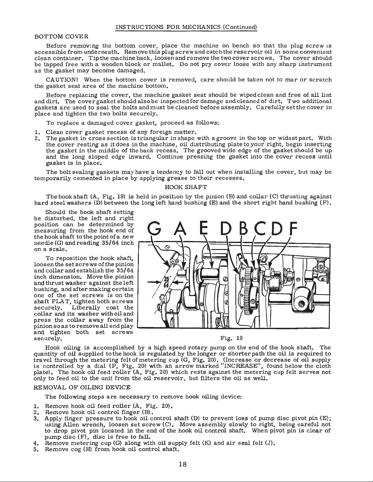
hook
steel
Should
disturbed,
hook
shaft
(G)
To
reposition
the
collar
dimension.
thrust
of
the
FLAT,
and
the
so
tighten
Hook
of
through
controlled
The
to
feed
The
following
ove
Remove
Apply
using
to
drop
pump
Remove
Remove
COVER
removing
from
free
with a wooden
may
seat
area
replacing
The
cover
used
tighten
cover
in
resting
in
long
is
in
sealing
cemented
shaft
washers
the
hook
the
can
be
from
to
the
and
reading
set
screws
and
establish
washer
and
after
set
screws
tighten
Liberally
its
wash
collar
as
to
remove
both
oiling
oil
supplied
the
by a dial
hook
oil
to
OF
OILING
hook
hook
finger pressure
Allen
disc ( F),
wrench,
pivot
metering
cog
(H)
the
underneath.
Tipthemachineback,
become
When
of
the
gasket
to
seal
the
two
gasket
cross
as
the
middle
sloped
place.
gaskets
(A,
Fig.
(D)
shaft
left
determined
the
hook
point
35/
the
hook
of
Move
against
making
both
er
with
away
all
set
is
accomplished
metering
oil
feed
the
unit
steps
oil
feed
oil
control
pin
located
disc
cup
from
INSTRUCTIONS
bottom
Remove
block
damaged.
the
bottom
the
machine
cover,
the
bolts
recess
section
it
edge
in
place
between
setting
and
of a new
64
the
the
the
the
certain
is
screws
coat
oil
from
end
screws
tothehook
(P,
roll
DEVICE
are
roller
loosen
is
(G)
hook
the
should
bolts
securely.
cover
of
is
does
in
of
the
inward.
may
by
19)
is
the
right
by
end
of
inch
shaft,
pinion
35/
64
pinion
left
on
the
the
and
the
play
felt
of
Fig
. 20)
er
froin
the
necessary
(A,
finger
to
hook
set
in
free
to
along
oil
(A,
FOR
cover,
or
cover
also
and
gasket,
any
triangular
the
back
have a tendency
applying
held
long
by a high
is
metering
(B).
oil
screw
the
fall.
with
control
place
this
plug
screw
loosenandremovethetwocoverscrews.
mallet.
is
bottom.
machine
must
foreign
machine,
regulated
with
Fig.
oil
Fig.
control
end
removed,
be
inspected
be
proceed
in
recess.
Continue
grease
HOOK
in
position
left
hand
speed
cup
an
20) y.rhich
reservoir,
to
remove
20).
(C).
of
the
oil
supply
shaft.
gasket
cleaned
matter.
shape
by
arrow
shaft
MECHANICS
the
machine
and
catch
Do
not
pry
care
seat
should
for
damage
before
as
follows:
with a groove
oil
distributing
The
grooved
pressing
to
fall
out
to
their
SHAFT
by
the
pinion
bushing
E
rotary
thelonger
(G,
Fig,
20).
marked
rests
against the
but
filters
hook
oiling
(D)
to
Move
hook
assembly
oil
felt
(K)
control
(Continued)
on
bench
the
reservoir
cover
recesses.
(E)
pump
prev
and
loose
should
be
and
assembly.
plate
wide
the
gasket
when
installing
(B)
and
the
Fig.
on
or
shorterpath
(Increase or
"INCREASE",
the
oil
device:
ent
slowly
shaft.
air
so
that
oil
with
be
taken
wiped
clean
cleaned
in
edge
and
19
the
loss
seal
of
Carefully
the
top
to
your
of
the
into
the
collar
short
right
end
of
decre
metering cup
as
well.
of
pump
to
right,
When
felt
in
any
not
and
dirt.
or
right,
gasket
cover
the
(C)
the
the
found
pivot
(J).
the
plug
some
The
cover
sharp
to
mar
free
Two
set
widest
begin
cover,
thrusting
hand
hook
oil
is
ase
of
below
felt
disc
pivot
being
pin
screw
convenient
should
instrument
or
scratch
of
all
additional
the
cover
part.
inserting
should
recess
but
may
against
bushing
shaft.
required
oil supply
the
serves
pin
careful
is
clear
lint
With
be
up
until
be
(F).
The
to
cloth
not
(E);
not
of
is
in
18
Page 19
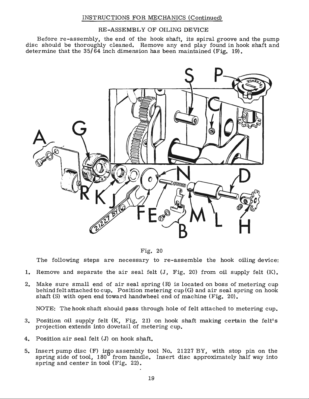
INSTRUCTIONS
FOR
MECHANICS
(Continued)
Before
disc
determine
should
re-assembly,
be
thoroughly
that
the
35/64
RE-ASSEMBLY
the
end
of
the
cleaned.
inch
dimension
OF
OILING
hook
Remove
has
shaft,
any
been
DEVICE
its
spiral
end
play
maintained
groove
found
(Fig.
in
19).
and
hook
the
shaft
pump
and
The
1.
Remove
2.
Make
behind
shaft
NOTE:
3.
Position
projection
4.
Position
5.
Insert
spring
spring
following
and
sure
felt
(S)
pump
and
with
The
oil
air
side
small
attached
hook
extends
seal
disc
of
center
steps
separate
end
open
shaft
supply
felt
(F)
tool,
in
to
cup.
end
felt
into
180
tool
are
the
of
toward
should
(K,
dovetail
(J)
on
inJo
from
(Fig.
necessary
air
seal
air
seal
Position
handwheel
pass
Fig.
of
hook
assembly
shaft.
handle.
22).
Fig.
through
metering
20
to
felt
spring
metering
21)
on
tool
Insert
19
re-assemble
(J,
Fig.
(R)
is
located
cup
end
of
machine
hole
of
hook
No.
shaft
cup.
21227
disc
the
20)
from
on
(G)
and
air
(Fig.
felt
attached
making
BY,
approximately
with
hook
oil
boss
seal
oiling
supply
of
metering
spring
20).
to
metering
certain
stop
half
the
pin
device:
felt
on
felt'
on
way
(K).
cup
hook
cup.
s
the
into
Page 20
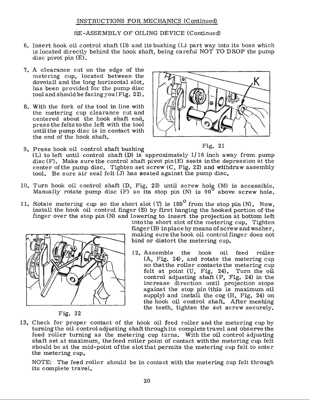
INSTRUCTIONS
FOR
MECHANICS
(Continued)
6.
Insert
is
disc
hook
located
pivot
7. A clearance
metering
dovetail
has
tool
8.
With
the
and
been
and
the
provided
should
fork
metering
centered
9.
press
until
the
Press
(L)
disc
center
tool.
the
the
end
to
(F).
pump
of
hook
left
ofthe
Be
felts
Make
sure
RE-ASSEMBLY
oil
control
directly
pin
cut
cup,
the
behind
(E).
on
located
long
for
be
facing
of
the
cup
clearance
about
the
until
to
disc
hook
oil
pump
air
the
the
left
is
shaft.
control
control
sure
the
disc.
seal
shaft
the
the
edge
between
horizontal
the
pump
you ( Fig.
tool
in
line
hook
shaft
with
in
contact
shaft
shaft
control
Tighten
felt
(J)
OF
OILING
(D)
and
hook
of
the
the
slot,
disc
22).
with
cut
and
end,
the
tool
with
bushing
(D)
is
shaft
set
has
DEVICE
its
bushing
shaft,
being
approximately
pivot
screw
seated
pin(E)
(C,
against
(Continued)
(L)
part
careful
1/
seats
Fig.
22)
the
way
NOT
Fig.
16
inch
in
and
pump
into
TO
21
away
the
depression
withdraw
disc.
its
boss
DROP
from
which
the
pump
pump
at
the
assembly
10.
11.
Rotate
install
finger
13.
Check
turningthe
feed
shaft
should
the
Turn
hook
Manually
metering
the
over
for
roller
set
be
metering
oil
rotate
hook
the
Fig.
proper
oil
turning
at
maximum,
at
the
cup.
control
pump
cup
oil
stop
22
contact
control
mid-point
shaft
disc
so
the
control
pin
(N)
adjusting
as
the
the
(D,
(F)
short
finger
and
of
the
shaftthroughits
metering
feed
roller
of
the
Fig.
so
its
slot
(B)
by
lowering
into
the
finger
(B)
making
bind
12.
Assemble
or
(A,
so
felt
control
increase
against
supply)
the
the
hook
cup
point
slot
that
23)
stop
(T)
first
to
short
in
sure
distort
Fig.
that
at
hook
teeth,
oil
turns.
permits
until
screw
pin
is
180°
hanging
insert
slot
place
the
hook
the
the
24),
the
roller
point
adjusting
direction
the
stop
and
install
oil
tighten
feed
roller
complete
of
contact
(N)
is
from
the
of
the
by
means
oil
metering
hook
and
contacts
(U,
pin
control
With
with
the
metering
hol0 (M)
90
above
the
stop
the
hooked
projection
metering
of
screw
control
cup.
oil
rotate
Fig.
the
24).
shaft ( P,
until
(this
the
cog
shaft.
the
set
and
the
travel
the
oil
the
metering
is
accessible.
screw
pin
(N).
portion
at
bottom
cup.
and
finger
feed
metering
the
metering
Turn
Fig.
24)
projection
is
maximum
(H,
Fig.
After
screw
securely.
metering
and
observe
control
cup
felt
hole.
Now,
of
the
left
Tighten
washer,
does
not
roller
cup
cup
the
oil
in
the
stops
oil
24)
on
meshing
cup
by
the
adjusting
cup
felt
to
enter
NOTE:
its
The
complete
feed
travel.
roller
should
be
in
contact
20
with
the
metering
cup
felt
through
Page 21
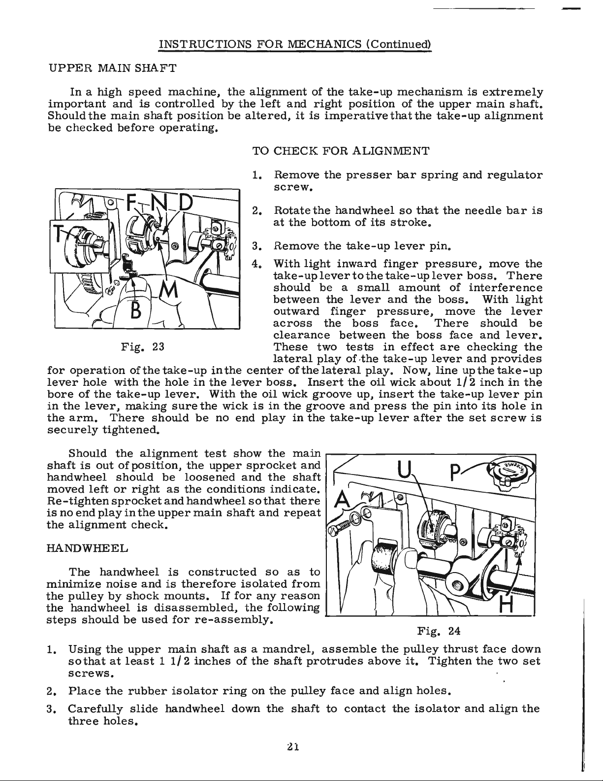
INSTRUCTIONS
FOR
MECHANICS
(Continued)
UPPER
In a high
important
Should
be
for
lever
bore
in
the
the
checked
operation
hole
of
the
lever,
arm.
securely
MAIN
speed
and
main
before
Fig.
of
with
the
take-up
making
There
tightened.
SHAFT
machine,
is
controlled
shaft
operating.
23
the
take-up
the
hole
lever.
should
position
in
sure
the
be
the
by
be
in
the
the
With
wick
no
alignment
the
altered,
TO
1.
2.
3.
4.
center
lever
the
is
end
left
and
CHECK
Remove
screw.
Rotate
at
the
Remove
With
take-up
should
between
outward
across
clearance
These
lateral
of
boss.
oil
wick
in
the
play
it
is
light
the
Insert
groove
in
the
of
the
take-up
right
imperative
FOR
the
presser
the
hand
bottom
the
take-up
inward
lever
be
a
the
finger
the
between
two
tests
play
of
lateral
the
groove
take-up
mechanism
position
of
that
the
ALIGNMENT
bar
wheel
of
its
so
stroke.
lever
finger
to
the
take-up
small
lever
amount
and
the
pressure,
boss
face.
the
in
effect
,the
take-up
play.
oil
up,
and
wick
insert
press
lever
Now,
the
after
the
upper
take-up
spring
that
the
pin.
pressure,
lever
boss.
move
There
boss
are
lever
line
about
the
take-up
pin
the
is
extremely
main
alignment
and
regulator
needle
boss.
of
interference
With
the
should
face
and
checking
and
up
the
1/ 2 inch
into
its
set
shaft.
bar
move
the
There
light
lever
lever.
the
provides
take-up
in
the
lever
pin
hole
screw
is
be
in
is
Should
shaft
is
handwheel
moved
Re-tighten
is
no
end
the
alignment
out
left
play
the
of
should
or
sprocket
HANDWHEEL
The
minimize
the
pulley
the
steps
1.
Using
so
handwheel
noise
by
handwheel
should
the
that
at
screws.
2.
Place
3.
Carefully
three
the
holes.
alignment
position,
right
in
the
upper
be
as
and
test
the
upper
loosened
the
conditions
hand
wheel
main
check.
is
constructed
and
is
therefore
shock
be
upper
mounts.
is
disassembled,
used
for
main
re-assembly.
shaft
least 1 1/ 2 inches
rubber
slide
isolator
handwheel
show
the
sprocket
and
the
indicate.
so
that
shaft
and
so
isolated
If
for
any
the
following
as a mandrel,
of
the
shaft
ring
on
the
down
the
main
and
shaft
there
repeat
as
to
from
reason
protrudes
pulley
shaft
r----:;;;,----
,.___
__
____..___.L..-_ ____._.,
assemble
face
and
to
contact
the
above
align
the
-
-----
Fig.
pulley
it.
Tighten
holes.
isolator
_ "--_,__
24
thrust
and
--:
____
face
the
align
:::====:::~
,
down
two
set
the
21
Page 22

INSTRUCTIONS
FOR
MECHANICS (
Continued)
HAND
4.
5.
6.
7.
8.
assembly
not
of
over
sliding
WHEEL ( Continued)
Three
handwheel.
The
Insert
lightly.
Loosen
revolve
for
the
other
The
freely
is
changes
lator
CAUTION!
to
damage
the
shaft.
the
plastic
outer
good
three
assembly
noted,
screws.
on
seal
handwheel
isolator
the
three
the
the
alignment.
screws
until
on
all
the
it
of
screw
the
the
The
gently.
"O"
rings
ring
screws
two
pulley
whole
shaft.
When
mainshaft,
surface
are
should
can
pressure
oil
seal
over
assembly
Now.
moving
snug.
If
be
replacing
Upper
seal
are
and
that
screws
gradually
from
run
true
any
sidewise
corrected
in
care
located
of
the
main
to
prevent
now
cap
are
several
as
the
the
must
near
ring
inserted
are
now
run
through
and
slowly
times
tighten
one
to
it
revolves
run-out
by
slight
three
handwheel
should
shaft
iso-
be
taken
the
should
damage
into
assembled.
the
the
end
be
lightly
be
to
the
their
complete
oiled
held
and
securely
take-up
respective
assembly
Fig.
the
handwheel
to
mechanism.
25
the
holes
and
tightened
right
in
the
worked
when
STITCH
After a feed
to
read
1.
Depress
2.
Turn
stitch
3.
Loosen
4.
With
-
window
5.
Tighten
TIMING
Tip
is
at
the
up
with
LENGTH
accurately.
the
the
handwheel
length.
the
stitch
the
change
on
the
indicator
THE
the
the
machine
top
of
mark
MACIDNE
its
INDICATOR
timing
stitch
belt
stroke.
on
change,
length
toward
length
button
guard.
dial
back
the
wall
against
The
change
indicator
still
set
screws.
timing
of
the
the
stitch
you
until
engaged,
the
rest
line
casting
length
button
the
set
screws.
set
:r.in
'4"
(A,
indicator
until
stop
the
and
on
the
Fig.
it
engages
is
reached,
indicator
turn
handwheel
feed
25).
will
dial
drive
have
to
be
in
the
feed
indicating
to
read
until
eccentric
the
re-adjusted
eccentric.
the
longest
"L"
in
the
needle
should
bar
line
22
Page 23

TO
1.
2.
3.
4.
5.
SET
THE
Remove
Remove
Turn
Loosen
Hold
11411
on
up
(A,
FEED
the
large
the
handwheel
the
the
handwheel
the
Fig.
INSTRUCTIONS
TIMING
needle
plug
from
screws
until
lower
sprocket
securely
adjustable
feed
25).
the
below
the
screws
driving
FOR
needle
the
needle
and
turn
MECHANICS
bar.
oil
gauge
bar
is
at
the
through
eccentric
the
the
lower
and
(Continued)
and
below
top
of
hole
below
main
shaft
mark
the
its
on
handwheel.
stroke.
the
oil
until
the
casting
gauge.
the
timing
wall
line
line
Press
6.
press
hole.
in
the
7. A
small
before
CAUTION!
LOWER
Should
(61432
be
J).
located . 020
The
is
accessible
HEAD
MECHANISM
The
points.
the
the
retighten
lower
quantity
they
MAIN
the
located
belt
should
through
needle
lower
lower
the
main
are
After
SHAFT
lower
between
inch
be
bar
main
sprocket
two
shaft
firmly
toward
sprocket
shaft.
oflead
seal
should
replaced.
any
feed
timing
main
from
shaft
the
the
position
hook
bushing.
assembled
the
large
plug
LUBRICATION
link
(A.
Figs.
toward
the
head
screws
be
securely.
applied
change,
be
altered,
driving
on
the
gear
lower
screw.
ADJUSTMENT
26, 27)
is
the
handwheel
of
the
on
the
the
hook
it
and
the
sprocket
lubricated
and
machine.
There
threads
must
is
important
left
lower
so
that
at
two
with a screwdriver,
Through
should
of
be
retimed.
main
the
both
second
be
no
plug
that
shaft
the
the
bushing.
set
access
end
screws
collar
screw
play
1.
Fig.
27
2.
Thrust
positioned
across
washer.
loosening
Position
(B,
through
bar
Proper
ed
ther
to
ing
Fig.
link
wick
by
bending
away
secure
with
washer
so
the
thin
Washer
left
bracket
27)
the
center
(A).
contact
from
the
spring
(B.
that
portion
hand
so
that
Wick
the
the
felt
clip
Fig.
oil
is
screw
by
means
wick
of
the
(C)
with
wick
needle
strip
61454
26)
wick
of
positioned
slot
must
the
support
(E)
23
must
(C)
the
(D).
of
(C)
in
contact
needle
bar
to
B.
be
wipes
thrust
by
screw
passes
needle
bearings
bracket
link
the
upper
the
(D)
as
required.
Fig.
needle
can
closer
needle
26
bearings.
be
obtainor
far-
Be
sure
bar
bush-
Page 24

24
Page 25
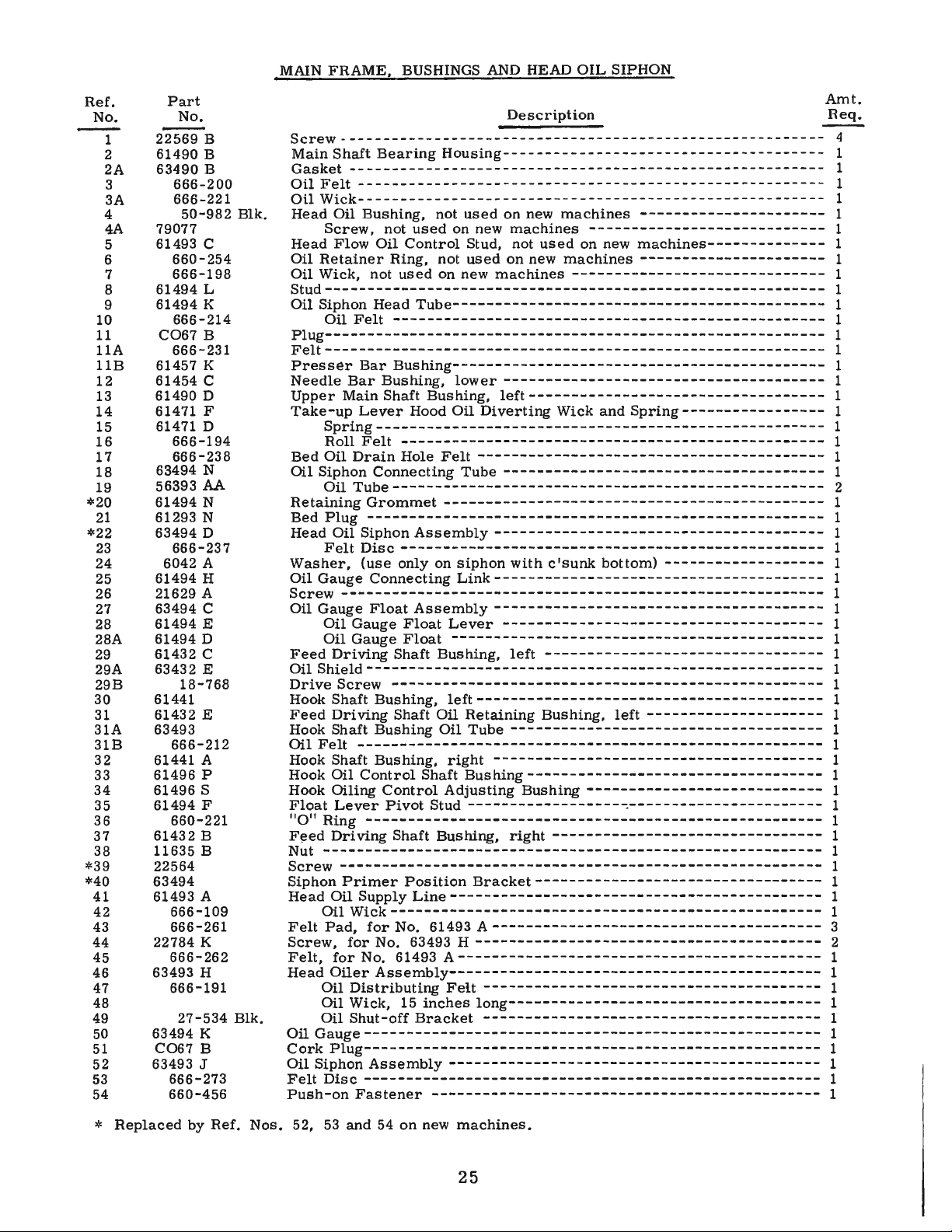
MAIN
FRAME, BUSHINGS
AND
HEAD OIL SIPHON
Ref.
No.
1
2
2A
3
3A
4
4A
5
6
7
8
9
10
11
llA
llB
12
13
14
15
16
17
18
19
*20
21
*22
23
24
25
26
27
28
28A
29
29A
29B
30
31
31A
31B
32
33
34
35
36
37
38
*39
*40
41
42
43
44
45
46
47
48
49
50
51
52
53
54
Part
No.
22569 B
61490 B
63490
666-200
666-221
50-982 Blk.
79077
61493 C
660-254
666-198
61494 L
61494
K
666-214
CO67 B
666-231
61457
K
61454 C
61490 D
61471 F
61471 D
666-194
666-238
63494 N
56393
AA
61494 N
61293 N
63494 D
666-237
6042 A
61494 H
21629 A
63494 C
61494
E
61494 D
61432 C
63432
E
18-768
61441
61432
E
63493
666-212
61441 A
61496 P
61496 S
61494 F
660-221
61432 B
11635 B
22564
63494
61493 A
666-109
666-261
22784
K
666-262
63493
H
666-191
27-534 Blk.
63494
K
CO67 B
63493
J
666-273
660-456
B
Description
Screw---------------------------------------------------------
Main Shaft
Gasket----------------Oil
Fell-------------------------------------------------------
Oil
Wick--- - - ----- --------- - - --- - - ---- ---- --- - - --- - - -
Head Oil Bushing, not
Screw,
Head Flow Oil
Oil
Retainer
Oil Wick, not
Bearing
not
used
Control
Ring, not
used
Housing--------------------------------------
-
--------------------------------------
used
on
new
on
new
Stud, not
used
on new
machines
used
on new
machines
machines
----------------------------
on new
machines
------------------------------
----------------------
machines--------------
----------------------
Stud----------------------------------------------------------Oil Siphon Head
Oil
Felt---------------------------------------------------
Tube--------------------------------------------
Plug----------------------------------------------------Felt----------------------------------------------------------Presser
Needle
Upper
Take-up
Bar
Bushing--------------------------------------------
Bar
Bushing,
lower--------------------------------------
Main Shaft Bushing,
Lever
Hood Oil
Diverting
left-----------------------------------
Wick and
Spring----------------Spring----------------------------------------------------Roll
Bed Oil
Oil Siphon Connecting Tube
Retaining
Bed
Head Oil Siphon
Washer,
Oil Gauge Connecting
Felt--------------------------------------------------
Drain
Hole
Felt
-----------------------------------------
--------------------------------------
Oil
Tube---------------------------------------------------
Grommet
---------------------------------------------
Plug------------------------------------------------------
Assembly---------------------------------------
Felt
Disc-------------------------------------------------(use
only on
siphon
with
c'sunk
bottom)
-------------------
Link---------------------------------------
Screw---------------------------------------------------------
Oil Gauge
Feed
Oil
Shield-----------------------------------------------------Drive
Hook Shaft Bushing,
Feed
Hook Shaft Bushing Oil Tube
Oil
Felt------------------------------------------------------Hook Shaft Bushing,
Hook Oil
Hook Oiling
Float
11011
F!:!ed
Float
Oil Gauge
Oil Gauge
Driving
Assembly
Float
Float--------------------------------------------
Shaft Bushing,
---------------------------------------
Lever
-------------------------------------left
---------------------------------
Screw---------------------------------------------------
left-----------------------------------------
Driving
Shaft Oil Retaining Bushing,
left
---------------------
-------------------------------------
right
Control
Lever
Shaft
Control
Pivot
Stud
Adjusting Bushing
---------------------------------------
Bushing-----------------------------------
----------------------------
-------------------::-----------------------
Ring------------------------------------------------------
Driving Shaft Bushing,
right
-------------------------------Nut----------------------------------------------------------Screw--------------------------------------------------------Siphon
Head Oil Supply
Felt
Screw,
Felt,
Head
Oil
Cork
Oil Siphon
Felt
Push-on
Primer
Position
Bracket----------------------------------
Line--------------------------------------------
Oil
Wick---------------------------------------------------
Pad,
for
No. 61493
for
No. 63493 H
for
No. 61493
Oiler
Oil
Oil Wick,
Assembly--------------------------------------------
Distributing
15
Oil Shut-off
inches
Bracket
A---------------------------------------
-----------------------------------------
A-------------------------------------------
Feit
----------------------------------------
long-------------------------------------
----------------------------------------
Gauge------------------------------------------------------
Plug------------------------------------------------------
Assembly
------------
--------
-----
---------
Disc------------------------------------------------------
Fastener----------------------------------------------
Amt.
-- ----- - -- 1
-
-----
--
--------
Req.
4
1
1
1
1
1
1
1
1
1
1
1
1
1
1
1
1
1
1
1
1
1
2
1
1
1
1
1
1
1
1
1
1
1
1
1
1
1
1
1
1
1
1
1
1
1
1
1
1
1
1
3
2
1
1
1
1
1
1
1
1
1
1
*
Replaced
by Ref. Nos. 52,
53
and
54
on new
machines.
25
Page 26

514
51-A
__
,..---..
26
Page 27

MAIN
FRAME, MISCELLANEOUS COVERS
AND
NEEDLE TENSION PARTS
Ref.
No.
1
2
3
4
5
6
6A
7
8
9
10
11
12
13
14
15
16
17
18
19
20
21
22
23
23A
24
25
26
27
28
29
30
31
32
33
34
35
36
37
38
39
40
41
42
43
44
45
46
47
48
49
50
51
51A
51B
52
53
54
55
56
57
58
59
60
61
62
63
64
Part
No.
22733 D
63494 A
63494 B
22815
22894 E
96
63482 A
61482 G
22516
61449 V
660-254 A
61449 U
660-254 B
61449 Y
61449 X
22504 A
61414 A
22528
22742
63402 B
91
A
61273
376
63494 B
61482 J
61482 H
22571 F
660-204
652-16
22644 K-64
61494 R
22570
660-219 A
29475
AS
61292 C
61392
F-9
61492 H
109
63453
61492 F
61492 G
61492 E
22560 G
660-269 A
22539 P
63494 K
61449 T
22570 A
61470 D
22805
61471 A
22564 B
63451
61471 B
22562
63494 B
22766
61470 C
HS24
C
63492
63470
90
63470 B
222 D
63470 A
22863 B
22597 E
Description
Plug
Screw,
for
oil
filler
hole - -- - - -- - --- - -- - --- --- --- - -- - -- - --- -- - -Gasket-----------------------------------------------------------Plug;
plastic-----------------------------------------------------Screw------------------------------------------------------------Screw------------------------------------------------------------Screw-------------------------------------------------------------
Gasket
Head
------------------------------------------------------------
Cover--------------------------------------------------------
Screw-------------------------------------------------------------
Stitch Regulating
Retainer
Stitch
Retainer
Stitch
Pawl
Screw---------------------------------
Bobbin
Ring - -- - -- - ----- ----- ----- -------- --- --
Regulating
Ring-- - -- - -------
Regulating
Plunger
Case
Plunger --- -- - --- ----------
- ---------- - -- ------ -- - -
---------- -- --- ---
Pawl------------------------------------
Pawl
- -- - -- - --- --- - -- -
Stud--
- ---
-- ------
-- --
--- - -- - -- - ------ -- - -
--- --- - --- -------
Spring-----------------------------------------------
Holder
Positioning
Finger-------------------------------
---------------------------
Screw-------------------------------------------------------------
Screw-------------------------------------------------------------
BedSlide----------------------------------------------------------
Screw----------------------------------------------------------
Bed Slide
Throat
Spring---------------
Plate
(see
pages
of
Feed
----- -----
Dogs and
------
Throat
----
Plates)--------------Screw------------------------------------------------------------Plug,
plastic-----------------------------------------------------Gasket-----------------------------------------------------------Oil
Reservoir
,f~i!;crew
110
Cover-------------------
--
---------
--
____________________________________________________ _
Washer-----------------------------------------------------------
Screw
Oil
------------------------------------------------------------
Distributing
Plate ---
----- -----------------------
Screw------------------------------------------------------------
Roll
Pin-----------------------------------------------------------
TensionAssembly
Tension
Tension
Tension
Tension
Nut----------------------------------------------------
Spring--------------------------------------------------
Release
Disc----------------------------------------------------
-------------------------------------------------
Washer-----------------------------------------
Take-upSpring-------------------------------------------------Tension
Tension
Tension
"Quad" Ring
Plug
Oil
Gauge--------------------------------------------------------Stitch Length
Screw
Frame
Post---------------------------------------------------
Set
Release
Post
Screw
Pin---------------------------------------------
Socket---------------------------------------------
---------------------------
-------
------
----------
--------
--
------
-------------- -
Screw--------------------------------------------------------
---
--------
Thread
Indicator-
Eyelet----------------------------------------------
- --
------
-------- ------------
-----------------
- -
----
- --------------- --- -
Screw------------------------------------------------------------Frame
Screw
Take-up
Take-up
ThreadEyelet-----------------------------------------------
-----------------------------------------------------------Shield-----------------------------------------------------
Lever
Hood - -------
----
------ ----- -- --- - -- - ----- -- - -- --- - Screw-----------------------------------------------------------Plug,
plastic------------------------------------------------------
Screw
Thread
Screw
Tension
Lower
Screw
Needle
Screw
Upper
Stop Screw,
Set Screw,
-----------------------------------------------------------Guide------------------------------------------------------
------------------------------------------------------------
Post
Eyelet------------------------------------------------
ThreadEyelet-----------------------------------------------
------------------------------------------------------------
Bar
Bushing
------------------------------------------------------------
Thread
for
for
Thread
Eyelet -------
tension
tension
assembly------------------------------------
assembly-------------------------------------
Guide------------------------------------
---
-----
---------------
-
---------
---------- -
---
----
---------------
--------------
-----
---
----
------
--------
-------- --
-------
-------
--- -
---
----
---
- -
Amt.
Req.
-
-
-
1
1
1
1
1
1
1
1
2
1
1
1
1
1
1
1
1
1
1
1
2
1
1
2
1
1
1
1
2
2
2
1
2
1
1
1
1
1
2
1
1
1
1
1
1
3
1
1
1
1
1
1
1
1
1
2
1
1
1
1
1
1
1
1
1
1
1
1
27
Page 28

28
Page 29

UPPEH SHAFT, PHESSEH
BAH,
NEEDLE
BAH
AND
FOOT LIFTEH MECHANISM
Hef.
No.
10
11
12
13
14
15
16
17
18
19
20
20A
21
22
23
24
25
26
27
28
29
30
31
32
33
34
35
36
37
38
39
40
41
42
43
44
45
46
47
48
49
50
51
52
53
54
55
56
57
58
59
60
61
62
63
64
65
66
67
68
69
70
71
Part
No.
1
2
3
4
5
6
7
8
9
22775
63457
J
230
61458 G
61458 FA
660-219 B
63457 H
61459 C
Presser
Screw----------------------------------------------------------------------
Presser
Screw---------------------------------------------------------------------Tension
Presser
Presser
Presser
22570
73
C
61356
61256 G
61457 B
63466
22890 A
421
H
61468 B
652 B-20
660-283 A
61468 D
9937
22874 F
61468 F
61468 E
22712 G
22817 A
61467
22758 B
15872 F
61421 B
Presser
Washer---------------------------------------------------------------------
PresserSpringHegulator-----------------------------------------------------
Lifter
Screw,
Lifter
Lifter
Lock
Fastener
Chain
Nut------------------------------------------------------------------------Screw----------------------------------------------------------------------Lifter
Bell
Screw----------------------------------------------------------------------Screw----------------------------------------------------------------------Lifter
Screw-----------------------------------------------------------------------
Lifter
Handwheel
22574 C
61421 G
61421 C
660-254 D
61421 E
61421 D
22894 V
61421 F
Stitch
22565 C
61460
Main Shaft
22884
61460 B
61454 A
63453 C
61454 B
666-186
660-254 C
61451 B
22564
29475 BC
29475 BH
22894 U
Feed
Upper Needle
Oil Shield
Felt
Oil
"O"
Take-up
Screw---------------------------------------------------------------------Main Shaft
Main Shaft
22894 V
22839
29486 L
Take-up
22784 E
61351 C
61451 A
61451 D-625
61451 D-626
61451 D-627
63452 A
61451
61455
63455
22757 D
61255
Needle
22562 B
61417 E
Needle
22768 A
660-269
660-456
666-273
63493
J
"Quad" Hing ----Push-on
Felt
Oil Siphon
Foot
(see
pages of
Presser
Bar----------------------------------------------------------------
Helease
Bar
Holl
Pin---------------------------------------------------------------Bar
Bar
Cam--------------------------------------------------------
Connection------------------------------------------------------
Spring
Washer---------------------------------------------------
Guide-----------------------------------------------------------
Screw------------------------------------------------------------------
Set
Screw---------------------------------------------------------------
Spring--------------------------------------------------------------
Lever----------------------------------------------------------------
left
thread
Lever
Lever
----------------------------------------------------------Chain----------------------------------------------------------Extension
Stud and
Washer----------------------------------------------------------------
-------------------------------------------------------------------
Hook------------------------------------------------------------------
Lever
Bell
Crank
Lever
Lever
Assembly
Crank------------------------------------------------------
Holler------------------------------------------------------------
Link-----------------------------------------------------------Spring
----------------------------------------------------------
---------------
Screw------------------------------------------------------------------
Hub
Washer-------------------------------------------------------------
Handwheel
Isolator
Handwheel
--------------------------------------------------------------
Washer---------------------------------------------------------
Isolator-------------------------------------------------------
Pulley------------------------------------------------------------------
Set
Screw-----------------------------------------------------------
Length
Set
Set
Driving
Holding Spring Clip
Indicator
-------------------------------------------------------
Screw---------------------------------------------------------------
Driving
Sprocket---------------------------------------------------
Screw---------------------------------------------------------------
Belt------------------------------------------------------------
Bar
Diverting
Bushing----------------------------------------------------
Felt------------------------------------------------------
------------------------------------------------------
Felt---------------------------------------------------------------------
Ring--------------------------------------------------------------------
Lever
Pin-----------------------------------------------------------
Assembly,
Assembly,
Spot
Screw--------------------------------------------------------------
Set
Screw---------------------------------------------------------------
for
Style 63400 A
for
Style 63400 B
Screw-------------------------------------------------------------------
Lever
and Needle
Bar
Screw-----------------------------------------------------------------Thrust
Take-up
Needle
Needle
Needle
Take-up
Take-up
Needle
Thrust
Washer----------------------------------------------------------
Lever
Bearing,
Bearing,
Bearing,
Link------------------------------------------------------
. 0625
inch
. 0626
inch
. 0627
Lever
Crank
inch
Pin-------------------------------------------------
Lever----------------------------------------------------------
Bar
Link---------------------------------------------------------
Washer----------------------------------------------------------
Screw-------------------------------------------------------------------
Bar
Connection--------------------------------------------------------
Screw-------------------------------------------------------------------
Bar------------------------------------------------------------------
Needle Set
Screw---------------------------
Fastener------------------------------------------------------------
----------------
Disc-------------------------------------------------------------------
Assembly-------
---------
Description
Feet)
--------------------------------------
Hook------------------------------------------
---------
---------------------------------
----------------------------------------
----------------------------------------
Link
Assembly
----------------------------------
diameter---------------------------------------38
diameter---------------------------------------38
diameter---------------------------------------38
--
------
---------
--------
-------
---------------
--------------
----------
----------
------
-------
------
------1
----------
Amt.
Heq.
1
1
1
1
1
1
1
1
1
1
1
1
1
1
1
1
1
1
1
1
1
1
1
1
1
1
1
1
1
1
1
3
1
1
3
2
1
2
1
2
1
2
1
1
1
1
1
2
1
1
1
1
1
2
2
1
1
1
1
1
1
1
1
1
1
1
1
1
1
1
1
29
Page 30

30
Page 31

FEED
DRIVING AND STITCH REGULA TING MECHANISM
Ref.
No.
1
lA
2
3
4
5
6
7
8
9
10
11
12
13
14
16
17
18
19
20
21
22
23
24
25
26
27
28
29
30
31
32
33
34
35
36
37
38
39
40
41
42
43
44
45
Part
No,
61432 H
22586
61360 G
22884
61460 A
22653 D-6
63443
22894 C
61432
J
73 C
719
61437 A
61437 B
61449 B
61449 S
22564 H
61437 L
22716 A
61437 M
29126
DD
61438 B
660-225
88
61437 N
12935 A
63433 A
22845
K
61434 G
63434 C
89
15037 A
63439
AL
22775 A
63439 A
22528
88
D
22768
22894
J
61336 U
61336
Y
90
61236
63435 A
61236 G
Description
Feed
Driving
Shaft----------------------------------
Screw-----------------------------------------
Thrust
Collar--------------------------------------
Screw-----------------------------------------
Feed
Driving
Shaft
Sprocket
-------------------------
Screw-----------------------------------------
Hook Shaft
Set
Driving
Gear
----------------------------
Screw--------------------------------------
Collar---------------------------------------------
Set
Screw-------------------------------------Screw--------------------------------------------Feed
Feed
Stitch
Stitch
Driving
Driving
Eccentric
Eccentric
Regulating
Regulating
Timing
Pivot
Eccentric
Eccentric
Collar----------------
Pin
--------------------
Thrust
Spring-------------
-------------------------Screw--------------------------------------------Feed
Drive
Eccentric
Retainer
Housing---------------
Screw---------------------------------------------
Retainer
Feed
Feed
Feed
Feed
Housing
Driving
Feed
Driving
Needle
Set
Screw----------------------------------
Driving
Screw--------------------------------------
Set
Lift
Link--------------------------------------
Lift
Link
Spring
Eccentric
Eccentric
Cover-----------------------
and
Connecting Rod
Connecting
Bearing-----------------------------
Eccentric
Stud
Thrust
Collar
---------------------------------
Assembly
Rod-----------
----------------
Washer--------------------------------------------
Feed
Bar------------------------------------------
Set
Screw--------------------------------------
Nut-----------------------------------------------
Feed
Feed
Screw--------------------------------------------Screw--------------------------------------------Feed
Screw---------------------------------------------
Screw---------------------------------------------
Feed
Feed
Screw--------------------------------------------Feed
Feed
Feed
Dog
Holder
Support
----------------------------
Screw-----------------------------------------
Dog
Holder-----------------------------------
Dog (See
Rocker
Rocker
pages
Shaft
Oil
of
Feed
Dogs and
Bushing---------------------------
Wick-------------------------------
Throat
Rocker---------------------------------------
Bar
Shaft
Rocker
-------------------------------------
Shaft----------------------------------
Plates)---
--
Amt.
Req.
1
1
1
2
1
2
1
2
1
2
2
1
1
1
1
3
1
2
1
1
1
1
1
1
2
1
1
1
1
1
1
1
1
1
1
1
1
2
2
2
1
2
1
2
1
31
Page 32

· ...•
~~
37 38
6
32
39
32
Page 33

ROT A TING
HOOK
ASSEMBLY
AND
HOOK
OILING
PAR
TS
Ref.
No.
1
2
3
4
5
6
7
8
9
10
11
12
13
14
15
15A
16
17
18
19
20
21
21A
22
23
24
25
26
27
28
28A
28B
28C
29
30
31
32
33
34
35
36
37
38
39
40
41
42
43
44
45
46
47
48
49
50
51
Part
No.
29474
61413
61413
22564
61413
61414
22716
22564
61216
61216
61415
61415
22564
61212
63407
63414
63407
22716
61210
63408
61411 A
22716
22565
22569
61351
12865
88
61444
89
61440
63432
HA73 B
61496
63496
61496
61496
61496
53678
22516
61496
61496
61496
35857
61496
61496
22819
61496
22894
61496
39198
61496
22743
E
G
F
N
B
J
666-181
666-182
C
D
R
L
K
27-527
P
R
N
660-221
D
M
P
E
G
F
F
C
B
E
N
A
E
A
A
B
H
M
H
C
V
B
Blk.
Description
Rotating
Thrust
Thrust
Hook
Hook
Thrust
Hook
Metering
Hook
Pivot
Retaining
Washer----------------------------------------------
Screw-----------------------------------------------
Air
Oil
Supply
Air
Pump
Pump
Spring----------------------------------------------Hook
Hook
Washer---------------------------------------------Screw----------------------------------------------Hook
Set
Screw,
Oil
Control
Oil
Seal
Spring
Oil
Control
Hook
Bobbin
Eyelet---------------------------------------
Screw---------------------------------------
Bobbin
Bobbin
Tension
Screw---------------------------------------
Bobbin
Bobbin
Bobbin
Bobbin
Stop
Bobbin------------------------------------------Hook,
Bobbin
Bobbin
Hook,
Washer
Collar
Screw-------------------------------------------
Shaft
Screw-------------------------------------------
Shaft
Collar
Set
Screw----------------------------------------
Shaft
Oil
Pin--------------------------------------------
Seal
Spring---------------------------------------
Seal
Felt-----------------------------------------
Disc------------------------------------------Disc
Oil
Control
Oil
Control
Oil
Control
Ring-----------------------------------------
Washer----------------------------------------
Set
Scre\v
Assembly-------------------------------
Case
Thread
Deflector
Pinion-------------------------------------
-------------------------------------------
Wick
Cup-----------------------------------------
Feed
Spring--------------------------------------
Felt
Pivot
for
Adjusting
Cog---------------------------------------
Assembly
Case---------------------------------Case
Case
Case
Case
Case
Screw-----------------------------------
Case
Case
Thread
Screw----------------------------------Hook
Hook-----------------------------------Hook
Screw-----------------------------------
Screw----------------------------------Set
---------------------------------------
----------------------------------------
---------------------------------------Insert
Roller----------------------------------
---------------------------------------
No.
----------------------------------------
Tension
Regulating
Latch
Latch
Latch
Latch----------------------------
Retainer.
Holder
Holder---------------------------
Assembly--------------------------
Thread
Thread
Screw--------------------------------
Pin---------------------------------Shaft---------------------------------
Finger-------------------------------
Shaft
61496
Shaft-----------------------------
----------------------------
Spring--------------------
Screw----------------------
Spring---------------------Hinge
Lever----------------------
Assembly---------------------
Retainer
Deflector
Retainer---------------------
Assembly-----------------------
Bushing-------------------------
P---------
Pin-------------------
Thread
Deflector
and
Thread
--------------------
-------------------
Amt.
Req.
1
1
1
1
1
1
1
1
1
1
1
1
1
1
and
1
1
1
4
1
1
1
3
1
2
2
1
2
1
2
1
1
2
1
1
1
1
1
1
1
1
1
1
1
1
1
1
1
1
1
1
1
1
1
1
2
1
33
Page 34

61324 J
L580
@
61424 C
i=::::::,
0~
61224 F
61305 K
61405 C
L579
61424 Y
61405 Y
0/ / //
©
c::1
61324
Q
/~
0
c::::J
61324 L
61205 D
61305
61305 M
Q
61424
J
612,AJ
~
61305 S
61405 J
9
61205 C
34
Page 35

THROAT
PLATE
AND
FEED
DOG
COMBINATIONS
Part
No.
L579
L580
61205
61205
61224
61224
61305
61305
61305
61305
61324
61324
61324
61405
61405
61405
61424
61424
C
D
C-043
F-063
K
M
Q
S
J-093
L-093
Q-073
C
J
Y
C-093
J-063
61424 Y-063
Teeth
No.
cut
L580,
With • 063
operations;
(.
085
inch
Teeth
cut
dresses
61224
Teeth
No.
C-043,
cut
61224
With • 043
rayon; • 063
•
073
and.
pants;
(.
085
feed
inch
With • 063
also
feed
(.
Teeth
and
foot
Teeth
plate
Teeth
throat
Teeth
throat
085
in
dog
inch
cut
similar
No.
cut
No.
cut
plate
cut
plate
With • 093
coats,
No.
With.
and
61320 S (.
093
similar
61320
S
With • 073
No.
(.
Teeth
125
L186;
inch
cut
between
No.
61420
Teeth
Teeth
No.
61424
61424
cut
cut
Y-063,
With • 093
between
(.
125
inch
With • 063
No.
61405
With • 063
hole
also
61220 J (.
22
per
inch,
presser
inch
needle
feed
foot
hole,
dog
thick)
22
per
and
16
inch
083
dog
inch,
other
61224
per
F-063,
needle
inch
inch
Nos.
for
light
C-063,
inch,
presser
hole,
needle
needle
61205
thick)
inch
needle
hole,
sizes • 083, • 093
No.
61205
D,
thick)
12
per
inch,
garments;
61320
12
61324
16
32
inch
inch
operations;
(.
085
inch
S .
per
inch,
per
inch,
No.
per
inch,
No.
needle
similar
125
needle
inch
needle
feed
for
L-093,
for
61324
for
61224
garments;
inch
hole,
thick)
dog
Q-073,
C-043,
hole,
feed
hole,
No.
thick)
16
per
inch,
pockets,
throat
C
22
per
J-063,
22
per
presser
inch
needle
pockets;
inch,
for
presser
inch,
hole,
feed
dog
foot
thick)
inch
needle
J,
inch
needle
available;
085
inch
hole,
presser
hole,
feed
thick)
Description
for
edge
No.
61220
for
edge
No.
L579,
plain
seaming
weight
presser
for
setting
foot
for
seaming
hole
hole
C,
for
for
for
61305
setting
inch
presser
for
seaming
throat
plate
seaming
presser
pants
foot
fly
presser
miscellaneous
presser
for
seaming
feed
thick)
for
seaming
dog
No.
for
pants
61305
for
sewing
plate
top
stitching
foot
No.
for
hemming
No.
61220
for
sewing
No.
61405
for
top
foot
for
dog
No.
hemming
No.
stitching
W
stitching
presser
on
material;
foot
pockets
No.
seaming
seaming
S,
presser
pockets
needle
foot
Nos.
heavy
No.
heavy
coats
No.
operation,
foot
seaming
foot
dog
No.
heavy
61305
fly
Q,
presser
pocket
No.
61424
shirt
61420
shirts,
J
pocket
C,
presser
stitching
61420
61405
pockets;
pockets
foot
dress
No.
shirts,
throat
No.
on
61320
and
61220
shirts;
hemming
J
AH,
dresses;
work
shirts
foot
of
dress
holes,
weight
61324
61320
heavy
61320
and
S
using
No.
No.
61305
coats,
M,
presser
for
AH,
trousers,
J-093,
trousers;
folder
61220
on
silks,
61220
weight
K,
trousers,
operations
foot
facings
with
C-093,
collars;
AH
throat
facings
with
foot
shirt
AH
collars;
(.
085
shirts, • 073
Y,
press
throat
and
61220
blouses,
plate
throat
61320
silk
also
in
and
No.
work
61320
presser
No.
J
trousers,
presser
foot
using
No.
chaining
presser
throat
plate
chaining
No.
61420
feed
inch
inch
er
foot
plate
similar
Nos.
plate
AJ
and
sizes
dress
61220
shirts,
shirts;
AJ
coats,
throat
Ll86;
rayons;
foot
and
No.
folder
61220
foot
plate
No.
dog
thick)
needle
No.
W
J
C
35
Page 36

61205 A
61424S
61424 G
61324 D
e
61405 S
61405 G
61224 C
61205
61424 N
61205 C
CA
61405 N
~
~61305D
61324 C
61305F
61324 R
61305 T
61305 C
36
Page 37

THROAT
PLATE
AND
FEED
DOG
COMBINATIONS
Part
61205
61205
61205
61224
61305
61305
61305
61305
61305
61324
61324
·
61324
61324
61405
61405
61405
61424
61424
61424
No.
A
C
CA
C-063
A
C
D
F
T
A-063
C-083
D-063
R-073
G
N
S
G-093
N-093
S-063
Teeth
semi-dress
61220
Teeth
dresses
61224
Teeth
throat
With.
•
feed
61220
Teeth
dungarees
No.
Teeth
throat
Teeth
plate
Teeth
material;
Teeth
and
With • 063
pants,
holes;
thick)
With • 083
suspenders;
No.
With • 063
operations;
dog
thick)
With • 073
pants;
presser
Teeth
61424
Teeth
denim,
61424
Teeth
plate
With • 093
operations;
(.
With • 093
canvas
presser
With • 063
dress
61420
cut
J,
cut
C-063,
cut
plate
063
083
inch
dog
C,
cut
61220
cut
plate
cut
No.
cut
cut
pants;
dungarees
feed
61305
No.
also
cut
G-093,
cut
N-093,
cut
No.
12 5 inch
and
BJ
and
16
per
pants;
61320
22
per
and
22
per
No.
inch
needle
needle
No.
61220
14
per
and
P
14
per
No.
14
per
61324
16
per
throat
22
per
throat
inch
dog
inch
also
C,
inch
also
61305
inch
in
foot
No.
14
per
14
per
canvas
22
per
61424
inch
feed
thick)
inch
other
foot
No.
inch
work
(.
125
inch,
throat
AB
inch,
other
presser
overalls;
inch,
needle
presser
needle
needle
size . 093
presser
presser
needle
needle
needle
light
inch,
61205
J,
inch,
inch,
inch,
inch,
No.
needle
D,
inch,
S-063,
inch
for
61224
hole,
hole
61320
61324
for
D-093,
for
plate
for
plate
hole,
and
overalls;
61305
in
sizes • 093, • 125
hole,
in
sizes • 073, • 083, • 093
61305
61220 P (.
inch,
and
inch,
dog
hole,
heavy
61320
shirts,
thick)
Description
for
plain
plate
for
plain
material;
foot
No.
hemming
C-073,
for
seaming
for
seaming
A,
61205
AB
(.
for
miscellaneous
throat
for
C-093,
miscellaneous
presser
miscellaneous
No.
miscellaneous
No.
hole,
foot
F,
hole,
for
foot
for
other
foot
for
presser
hole
No.
weight
AA
hole,
feed
plate
hemming
61324
61324
for
also
A,
presser
No.
for
tacking
presser
for
inch
125
cording
No.
miscellaneous
heavy
No.
run
for
61405
for
miscellaneous
(.
125
for
dog
seaming
No.
seaming
61220
presser
C,
085
presser
foot
D-073,
R-093,
miscellaneous
for
61320 C (.125
seaming
needle
inch
couch
L220
61320
stitching
foot
cording
materials;
inch
run
on
61224
on
throat
J
shirts,
foot
dresses;
work
61205
inch
thick)
operations
No.
61324
high
in
hemming
back
foot
seaming
No.
operations
presser
seaming
presser
sizes • 093, • 125
foot
inch
flies
foot
operations
hole;
thick)
covers;
materials;
AA
collar
No.
6-1420
couch
G,
presser
thick)
stitching
No.
61405
work
C-073,
dress
plate
using
No.
also
shirts
CA,
61320
No.
to
No.
seaming
presser
A-093,
overall
No.
foot
operations
operations
61220 P (.
high
needle
inch
overalls
inch
needle
61320
feed
operations;
BJ
covers
operations
feed
dog
collar
S,
shirts,
presser
shirts,
No.
hemmer
61220
and
61320
operations;
dress
61224
J
in
sizes • 073,
dress
on
work
presser
suspenders;
C
AA
on
light
No.
61320
foot
No.
inch
back
holes;
thick)
and
holes;
Q
(.
on
coats
dog
No.
throat
operation
throat
foot
presser
and
No.
op
era
plate
plate
No.
on
61405
and
foot
No.
blouses,
C-043,
No.
L96,
pants;
foot
No.
pants,
foot
throat
weight
AA
on
coats
61220
on
work
needle
125
inch
overall
feed
085
61305
dog
similar
feed
inch
and
No.
No.
throat
similar
L220
denim,
tions
foot
No.
N,
P
T,
on
on
37
Page 38

~~
61205 E
61324 U
~
61305 U
c:=::=,o
61424 M
0
@
61424 X
...........
______
61224 B
i===:,
e
61405 M
~~
61405 X
o_ e
61405 Z
@ ½
, ~
~
61424
AM
n
61405
AN
e;:;9
~
//
~~
~ - @
L391
.~
61205 B
61405 H
~
·"~~
L369
38
61424 K
61405 K
L549
L550
Page 39

THROAT
PLATE
AND
FEED
DOG
COMBINATIONS
Part
L369
L391
L54
L5
5 0
61205
61205
61224
61224
61305
61324
61405
61405
61405
61405
61405
61405
61424
61424
61424
61424
No.
9
B
E
B-063
E-063
U
U-063
H
K
M
X
Z
AN
K-063
M-063
X-063
AM-053
Teeth
No.
With • 063
No.
With
feed
Teeth
throat
Teeth
similar
61220
Teeth
61224
With.
• 093
61405
With . 063
61205
(.
Teeth
throat
With . 063
61305
Teeth
plate
Teeth
throat
Teeth
No.
Teeth
61424
Teeth
and
No.
Teeth
inch
presser
With
shirts;
thick
With . 063
No.
With . 063
No.
With
edge
foot
L391,
L369,
. 07 3
dog
085
cut
61424
similar
61420
margin;
. 063
61405
61405
• 053
Nos.
cut
cut
plate
cut
garments;
B,
cut
E-063,
063
inch
Z,
E,
inch
plate
U,
cut
No.
cut
plate
cut
cut
X-063,
cut
cut
feed
at
front
stitching
22
presser
inch
presser
inch
No.
16
16
61220
16
inch
needle
presser
inch
presser
thick)
22
inch
presser
22
61424
16
22
M-063,
22
22
AJ
22
foot
inch
inch
M,
inch
X,
inch
61420
per
per
inch,
foot
needle
foot
needle
L550,
per
inch,
No.
L549,
per
inch,
throat
C
per
inch,
presser
needle
hole
foot
needle
foot
inch,
No.
61324
needle
foot
per.inch
H-063,
per
inch,
No.
61424
per
inch,
presser
per
inch,
presser
per
inch,
garments;
per
inch,
throat
Nos.
dog
needle
No.
and
. 2 03
needle
presser
needle
presser
needle
shirts
AM,
61420
for
No.
hole,
No.
hole
for
presser
for
attaching
presser
for
plate
for
hemming
foot
No.
hole,
for
for
plate
61405
and
for
for
No.
hole,
No.
hemmingwork
U-063,
hole,
No.
binding
presser
for
sleeve
K-063,
for
attaching
for
foot
No.
for
edge
throat
for
Nos.
AM,
hole,
K,
inch
hole,
foot
hole,
foot
No.
hole;
dresses;
61420
Description
hemming
61320
for
61320
attaching
hemming
work
61220
for
61420
for
61420
foot
hemming
plate
miscellaneous
for
thick
for
No.
for
also
CM(.
AJ
hemming
AJ
foot
No.
sleeve
foot
No.
No.
61224 ·B-063,
work
61420
hemming
shirts,
B,
hemming
BN
presser
hemming
BN,
and
hemming
foot
facings
presser
No.
61420
6142
0 X
stitching
No.
61424
61420
presser
CM
sleeve
at
back)
attaching
61420
hemming
61420
in
size . 063
feed
085
(.
sleeve
BN
No.
yokes
BO
X (.
inch
handkerchiefs;
handkerchiefs;
085
inch
thick)
facings
61420
61420
work
house
61220
work
(use
shirts
foot
work
L82
L380
on
foot
on
pockets
61224
AM-053
facings
foot
yokes
rayon
dog
facings
shirts,
shirts;
(use
dresses;
feed
C
shirts;
with
and
No.
shirts;
A
flannel
sport
No.
to
shirts;
BD
rayon;
B-063,
edge
No.
(.
085
085
inch
inch
No.
thick)
H (.
H
presser
throat
with
dog
(.
bindingplastics;
61420
(.156
and
61420
throat
on
stitching
or
on
61420 H (.109
to
shirts;
inch
material;
61405
throat
to
work
125
inch
to
work
dresses
plate
plate
also
No.
085
inch
feed
plate
BN,
feed
inch
shirts;
work
H
throat
dresses,
presser
61424
sport
thick)
thick)
needle
AN,
plate
feed
dog
shirts;
thick)
shirts;
and
foot
No.
No.
hemmer)
in
size
61205
dog
hemmer)
dog
plate
with 1 /2
AM-063,
thick)
No.
L82
No.
thick)
throat
shirts;
plate
No.
shirts
foot
B,
A
and work
inch
feed
dog
feed
dog
hole
for
presser
39
Page 40

LS4
L437
L438
LSS
L222
a
·z ;
~
o I
/"
12
L28
Ill~
--
@
1
~ )
L223
&:"'iJ
L29
f/
f
@
61324 N
/
/~
C A
@
61424 L
61324
0
fij
61305
0
~
61305 N
h
61405 L
61424 R
61424
61405 R
40
AH
61405
AH
Page 41

THROAT
PLATE
AND
FEED
DOG
COMBINATIONS
Part
61305
61305
61324-063
61324
61405
61405
61405
61424
61424
61424
L2
L29
L54
L55
L222
L223
L437
L43
No.
8
8
N
N-063
L
R
AH
L-063
R-073
AH-063
With . 063
feed
dog
Teeth
With . 063
Teeth
With . 063
Teeth
With . 083
Teeth
Teeth
Teeth
throat
With . 063
With . 063
Teeth
Teeth
plate
Teeth
presser
With.
presser
With . 073
feed
With . 063
dress
bottom
cut
plate
feed
roller
plate
presser
feed
dog
throat
dog
No.
on
right
No.
L437,
wool
61320
and
wool
feed
shirts;
61305
61424
and
61424
61405
dog
063
dog
No.
dog
presser
cut
No.
cut
plate
cut
cut
trousers;
B
cut
plate
N,
cut
L-063,
cut
No.
cut
sport
AH-063,
and
AH,
No.
inch
needle
No.
L29,
16
per
L28,
inch
No.
16
per
L54,
foot
swing-out
inch
neelde
No.
L223,
16
per
No.
inch
L438,
and . 190
16
per
presser
16
per
16
per
No.
inch
needle
trousers;;
No.
inch
also
presser
16
per
16
per
61424
22
shirts
foot
inch
foot
inch
No.
inch
sport
L253
63430
in
presser
per
bottom
needle
No.
61405
Description
hole,
presser
inch,
needle
L55,
foot
presser
needle
presser
61305,
needle
needle
needle
for
presser
presser
swing-out
inch,
inch,
inch,
for
hole,
presser
inch,
L222,
inch
for
foot
inch,
throat
for
61324
hole,
also
sizes • 073, . 093
foot
inch,
inch,
R-073,
inch,
and
L253
hole,
61420
R,
shirts
compound
D (. 0 85
for
foot
miscellaneous
foot
No.
hole,
hole,
thick
presser
hole,
No.
for
foot
for
compound
hole,
hole,
for
assembly
miscellaneous
foot
No.
assembly
for
foot
for
top
presser
for
foot
No.
at
binding
No.
L440
for
miscellaneous
plate
miscellaneous
N-063,
for
in
sizes . 073, . 093
for
61320 R (.125
binding
No.
sewing
presser
for
top sti
wash
for
BE
(.
for
presser
for
and
wash
presser
inch
miscellaneous
No.
L30
hemming
L30
miscellaneous
foot
No.
61420
No.
61420
top
No.
stitching
foot
binding
L440
back)
operation
No.
presser
miscellaneous
foot
miscellaneous
61420
foot
tching
and
presser
binding
085
inch
sewing
foot
top
thick)
BA;
No.
K67092
stitching
L768
No.
(.
61324-093,
No.
inch
rayon
BE
zipper
No.
wear
rayon;
thick)
No.
stitching
and
wear
bar
hemming
(.
085
inch
seaming
BA;
K67092
seaming
also
for
collars
(.
085
collars
L768
operation
090
inch
on
jackets;
operations
operations
foot
No.
operations
inch
61320 B (.
operations
needle
inch
material;
tabs
collars
material;
zipper
61420 V (.
assembly,
holes
thick)
to
61420
bar
assembly,
feed
collars
material:
tabs
thick)
ope
also
(.
0 85
on
leather;
use
of
inch
of
on
thick
presser
on
61320
085
throat
pants
V
and
cuffs
throat
dog
to
085
operations;
ations;
on
leather;
for
use
inch
with
dress
thick)
dress
jackets;
at
front
throat
on
cotton
foot
work
R
on
needle
inch
on
feed
dog
plate
flies;
on
plate
63430
No.
61405
pants
inch
and
cuffs
feed
dog
presser
throat
with
thick)
throat
roller
shirts;
shirts;
feed
and
plate
and
No.
shirts;
cotton
holes;
thick)
work
No.
No.
throat
dress
No.
D
L,
flies;
thick)
on
No.
foot
41
Page 42

61424 T
61324 B
61305 B
'-----=p=61=4=:4==U~-O~
t_.:::::::=::=?o~~@:J
61324E
61405
T
h
61405 U
~~
~
61305 E
61424
61424
L916
Z
AF.
61405
61405
L
AE
61324 F
61305 G
0
61424
©
~
~L916
61305 B
61424
42
AA
AB
61405
61405
AA
AB
Page 43

THROAT
PLATE
AND
FEED
DOG
COMBINATIONS
Part
L916
61224
61305
61305
61305
61324
61324
61324
61405
61405
61405
61405
61405
61405
61424
61424
61424
61424
61424
61424
No.
D-063
B
E
G
B-063
E-063
F-063
L
T
U
AA
AB
AE
T-093
U-093
Z-063
AA-063
AB-053
AE-053
Teeth
With.
type
Teeth
throat
Teeth
pants;
Teeth
With . 063
With.
No.
With . 063
garments;
presser
Teeth
plate
Teeth
heavy weight
foot
Teeth
materials;
Teeth
medium
61424
Teeth
wash
foot
Teeth
throat
With • 093
feed
With.
feed
With . 063
feed
Wi
on
needle
(.
With • 053
w
feed
With . 053
materials;
(.
cut
materials;
foot
No.
063
binder;
61305
inch
plate
vests;
Nos.
and
th • 063
eight
B,
thick)
cut
cut
cut
No.
61305
063
pants.
61305
cut
No.
cut
No.
cut
cut
AA-063,.
cut
and
No.
cut
plate
dog
093
dog
dog
medium
125
inch
wash
dog
125
inch
plate
throat
also
hole;
22
inch
foot
16
weight
61420
22
inch
No.
No.
per
inch.
throat
61220
61305
16
16
16
61324
inch
inch
inch
16
61424
61220
22
22
wear
inch
No.
No.
inch
inch needle
inch
inch needle hole,.
needle
also
per
No.
per
plate
per
in
B,
needle
also
E,
presser
also
No.
per
16
per
materials;
per
throat
per
per
per
inch.
No.
needle
61405
needle
61405
needle
61405
weight
feed
thick)
and
614
feed
thick)
needle
needle
inch,
H
sizes . 073
in
H
materials;
AV
wear
for
sewing
plate
H,
inch,
61324
inch.
No.
inch.,
F-093,
L916,.
in
size.
L290
inch.
Z-063.
inch,
plate
inch,.
wash
presser
inch,.
61424
L,
wash
dog
needle
05
AB,
dog
Nos.
hole.
in
size • 073
L916.
for
B-063,
for
61324
for
presser
hole.
presser
hole,
sizes • 073, . 093
foot
hole.
093
(.
for
presser
for
for
miscellaneous
No.
for
and
foot
for
for
edge
AE-063.,
hole,.
T,
presser
hole,.
U,
presser
hol
presser
hol
e,
and
No.
hole.,
materials.
presser
No.
Description
bias
61224
for
binding
inch
presser
edge
miscellaneous
edge
for
••
083, • 093
for
No.
for
inch
0 85
inch
miscellaneous
miscellaneous
throat
61424
miscellaneous
No.
miscellaneous
throat
stitching
for
for
general
e,
for
for
wear
61405
for
for
61405
feet
stitching
presser
E-063,
stitching
feet
edge
foot
miscellaneous
L266
edge
needle
thick)
foot
plate
U-093,
wear
61420
plate
presser
miscellaneous
foot
foot
miscellaneous
foot
No.
misc
materials,
AA.,
miscellaneous
also
foot
edge
AE,
strips
D-063.
operations.
presser
Nos.
stitching
No.
(.
No.
on
No.
seaming
No.
ellaneo
in
No. 61420 BV
presser
on
61324
needle
Nos.
foot
inch
inch
085
stitching
hole;
No.
seaming
materials;
BU
No.
61420
presser
siz
stitching
61220
on
No.
operations
coats
61320.
needle
61320
needle
inch
feed
binding
61420
binding
61424
presser
seaming
seaming
61424
wash
foot
No.
61220
medium
61220 P (.
us
also
e .
063
dresses
hole;
suit
foot
on
operations
and
binding
H
binding
BE
seaming
foot
foot
and
B-063.
used
feed
H,
coats
61320
No.
and
L290
suits,
holes;
(.
085
holes;
thick)
coats
dog
operations;
BE
operations
T-093,
on
medium
foot
operations
throat
on
AB-063,
wear
61420
(.
125
085
(.
085
in
size . 053
No.
seaming
inch
(.
125
on wash and
No.
presser
with
dog
61320
and
on
coats
L266
vests;
coats
feed
inch
on
feed
and
No.
61305
presser
No.
61220
plate
light
presser
materials;
BY
operations;
inch
weight
inch
operations;
inch
op
erations
61420
on
needle hole
inch
61420
similar
English
Nos.
(.
085
vests;
and
throat
and
dog
thick)
coats
dog
similar
G,
throat
on
weight
on
No.
weight
thick)
work;
thick)
thick)
inch
BU
light
thick'
weai
B~
P
43
Page 44

61420
BW
63420
D
61424
61430
61430
AN
AK
AC
61430
61430
61405
AE
61430
AD
AL
AC
61430
61430
CB
AH
61405
63471
I
605
AD
61430
57
WB
61330 B
AP
HA73
61424
61430
~
28
B
B
AD
AG
61430
57
AF
WC
61430
CA
61430 AJ
57
WD
' "
73
44
A
73
C
604
22564 B
Page 45

AUTOMATIC
CHAIN
CUTTING
COMBINATIONS
AND
NIPPER
SPRING
ASSEMBLY
Part
21390
22564
29480
29480
61330
61330
61405
61405
61420
61424
61424
61430
61430
61430
61430
61430
61430
61430
61430
61430
61430
61430
61430
63420
63471
63471 A
No.
28 B
57
57
57
73
73 C
HA73 B
604
605
AD-063
AD
AE
AF
AG
AH
AJ
AK
AL
AN
AP
CA
CB
D
WB
WC
WO
A
BE
B
CR
cs
B-29
B-39
AC
AD
BW
AC-063
Screw,
Nipper
29480
Nipper
29480
Nipper
29480
Screw,
Screw,
Screw,
Screw,
Screw,
Nipper
spring
attaching
Screw,
Automatic
21390
presser
Automatic
21390
presser
Hinge
Hinge
Feed
Feed
Presser
Throat
assembly
Throat
assembly
Presser
Presser
Presser
Presser
Chain
Torsion
63420
Spring
Yielding
Chain
Chain
Adjustment
Adjusting
Presser
Nipper
29480
Nipper
assembly
for
Spring
CR,
Spring,
CS
Spring
CR,
for
for
for
for
for
Spring
for
BE,
BE,
Pin,
Pin,
Dog,
Dog,
Foot,
Plate, • 063
Plate, . 063
Foot
Foot
Foot
Foot
Cutter
D
Guide,
Cutter,
Cutter,
Foot,
Spring
CR,
Spring
chain
Plate,
29480
for
and
nipper
Stud,
29480
spring
adjusting
chain
spring
spring
Assembly
No.
Spring,
57
screw,
nipper
Chain
feed
foot
No.
Chain
feed
foot
No.
29/64
39/64
for
for
for
No.
No.
Bottom,
Shank,
Bottom,
Shank,
Spring,
for
Section,
marked
marked
Slide,
Pin,
for
for
Base,
29480
No.
cutter
for
CS
and
automatic
spring
for
CS
and
No.
61430
pin
cutter
guide
WC,
Cutting
dog
Cutting
dog
inch
automatic
automatic
29480
29480
for
presser
Assembly
21390
No.
guide
nipper
63471
spring
No.
61420
No.
63420
long
inch
automatic
inch
CR
inch
CS
for
for
for
for
for
bottom
for
"G"
"H"
for
presser
automatic
for
CS
and
BE
Description
No.
61430
automatic
nipper
chain
assembly
automatic
nipper
AJ
No.
61430
No.
61430
61430
No.
61430
(nipper
spring
nipper
base
Assembly
61405AC,
BW
Assembly
61405
D
for
long
chain
needle
needle
presser
presser
presser
presser
presser
feet
presser
for
for
presser
feet
automatic
nipper
Mounting
spring
No.
AD,
presser
for
chain
chain
hole
hole
on
Nos.
presser
presser
Nos.
chain
AP
chain
spring
cutting
chain
spring
CB
AN
AK
on
AK
on
spring
63471
(nipper
throat
(nipper
throat
presser
cutting
cutting
cutting
for
for
foot
foot
No.
foot
foot
No.
feet
presser
61420
feet
feet
61420
cutting
chain
spring
Bracket,
cutting
assembly
assembly
No.
21390
cutting
assembly
presser
presser
plate
stud
base,
plate
plate
foot
assembly
assembly
assembly
automatic
automatic
No.
61420
No.
63420
63420
Nos.
feet
BW,
Nos.
foot
No.
foot
No.
Nos.
BW,
assembly
cutting
assembly
foot
No.
No.
63471 A
spring
No.
spring
No.
No.
63420
foot
61420
BW
D
61420
Nos.
63420
61420
61420
63420
61420
63420
for
assembly
No.
Nos.
BE
assembly
foot
57 WO,
No.
BW
D
assembly
29480
No.
No.
No.
57
WB,
bracket
assembly
61424
assembly
61424
D
61420
No.
No.
No.
chain
chain
BW,
61420
D
BW,
BW
D
BW,
D
No.
No.
21390
nipper
Nos.
21390
CR,
Nos.
21390
61420
63420
nipper
22564
No
AC-063,
No.
AD-063,
29480
29480
29480
cutting
cutting
63420
BW,
63420
63420
29480
Nos.
spring
BE
BE
BW
D
B
.
BW
CR
CS
CR
D
D
D
CS
BE
45
Page 46

61420
AN
L440
61220
S
61220 W 61320
AG
61320
AH
61320
AJ
61420
L86 A
61420
L412
A
61420 B L498 A
61420
AP
61220 K
61220 61220
61420 AR 61420
AT
Q
L525
L943
L293
61420
CM
61420
46
BR
61420
BT
61420
AS
Ll58
Page 47

Part
No.
L86
A
Ll58
L293
L412
L440
L498
A
L525
L943
61220
61220
61220
61220
61220
61320
61320
61320
61420
61420
61420
61420
61420
61420
61420
61420AT
61420
61420
61420
K
Q
S
W
AG
AH
AJ
A
B
AN
AP
AR
AS
BR
BT
CM
For
welt
dog
No.
For
miscellaneous
throat
spring
For
miscellaneous
61324-063
nut
No.
For
making
61324
For
binding
L437
For
hemming
plate
No.
hinge
For
hemming
plate
No.
For
miscellaneous
61324
hinge
For
pants
No.
61324
For
attaching
(shank
For
hemming
No.
61330
For
stitching
No.
61224
61230
For
edge
(shank
No.
51930,
For
edge
No.
61224
No.
61330
For
edge
No.
61224
No.
61330
For
edge
No.
61224
61330
For
stitching
throat
For
second
throat
For
second
plate
For
For
For
For
For
For
For
For
No.
setting
61224
one
No.
61305A,
miscellaneous
No.
61205
miscellaneous
61324
hinge
miscellaneous
61205
miscellaneous
61324
nut
No.
miscellaneous
61324
nut
No.
sleeve
or
61424
hinge
pin
NOTE:
seaming
61305
plate
No.
51430
A-093
61224
pin
No.
61224
U-063
pin
No.
fly
No.
C-063
M,
spring
stitching
No.
stitching
AL,
stitching
AN,
stitching
C-063
AS,
spring
plate
plate
61224
C-063
operation
E,
U-063
pin
No.
C,
throat
U-063
51430
U-063
51430
facing
AM-063
No.
See
pants
C,
throat
No.
1230
(shank
pants
operations
Q-073
61330AC,
AC,
hinge
C-063
C-063
operation
operation
shirt
61344
B)
No.
F)
flies
(shank
work
and
C-063
61330
cuffs
and
C-073
(shank
61330
operations,
(shank
sleeve
61230
No.
No.
(spring
throat
(shank
(shank
facings
pants
flies;
bottom
shirt
pockets,
(shank
No.
pockets,
X,
pin
shirt
(shank
spring No.
shirt
(shank
spring
shirt
(shank
No.
down
waistbands
61324
61224
C-063
pockets, 1 /32
pants
edge
throat
operations
(shank
61330
operations
plate
F,
hinge
F,
hinge
operation;
(shank
61330
page
PRESSER
one
operation,
plate
seaming,
A-093
house
No.
seaming
No.
B-29)
plate
No.
B-29)
seaming
No.
seaming
No.
B-35)
78
dress
61330
on
B-35)
bottom
51930,
bottom
No.
No.
51930,
A-093
attaching
attaching
No.
plate
No.
AH,
with
folder
61330
jackets
dress
(shank
collar
(shank
61330
using
No.
to
shirts;
No.
feed
No.
61330
right
No.
hinge
left
No.
61330
pockets,
No.
51930,
pockets,
No.
51930,
pockets,
No.
61230
C-063
51930,
fly,
for
No.
stitching, 1 /32
No.
61330
61224
61330
pin
No.
61330
pin
No.
feed
No.
for
sewing
Description
No.
61324
chaining
(bottom
operations;
bottom
No.
AC,
and
shirts,
No.
61230
bands,
No.
61330
on
plastics;
AH,
folder
61330,
61330AD,
dog
No.
AE,
side,
61230
pin
side
61230
B-35)
right
61330
hinge
left
61330
hinge
left
X,
hinge
on
pants,
collars,
collars,
inch
hinge
medium
61324
61224
on
plastics;
AH,
on
silk,
C-063
on
plastics;
AH,
bottom
61330
on
plastics;
AH,
bottom
61330
dog
61330
-
47
FEET
split
C-093
section
No.
61330
No.
L464;
spring
feed
S,
yielding;
AK,
AP,
pin
margin;
A-093(shank
adjusting
AH,
No.
work
shirts;
use
plate
X,
use
hemmer
AC,
No.
bottom
dog
61205
spring
yielding;
bottom
No.
V,
side
bottom
pin
yielding;
bottom
pin
yielding;
bottom
No.
both
right
left
screw
weight
inch
rayon,
B-31)
B-31)
61405
adjusting
feed
spring
61330
left
yielding;
side
feed
No.
feed
No.
adjusting
side
side
E-063
No.
bottom
Ll
No.
No.
feed
No.
No.
61330
feed
No.
margin;
(hinge
feed
and
margins
shank
(welt
behind
W,
feed
61330
feed
51930)
feed
hemmer;
folder;
hinge
dog
screw
86;
feed
61330
61405
No.
C,
throat
No.
feed
No.
61230
B-31)
dog
yielding
No.
61330
feed
No.
61330
feed
No.
61330
B-35)
sides
side
yielding;
dog
22799
materials;
No.
pin
dog
screw
light
dog
61430
dog
61430
AN,
screw
of
for
No.
guide
needle;
yielding
dog
No.
Y,
adjusting
dog
No.
dog
feed
No.
61330
feed
pin
No.
No.
No.
dog
Y,
K,
51930,
plate
51930,
dog
L,
No.
section
feed
dog
61330
B-35)
dog
61330
B-31)
dog
AR,
yielding;
yielding;
feed
No.
H)
61330,
edge
No.
No.
No.
weight
No.
T,
adjusting
No.
Y,
adjusting
throat
presser
23133 F welt
screw
feed
section
61305,
61305
No.
L438,
dog
No.
AR,
dog
61330
61305
22840
throat
L57
guide
61305
22840
61305
61305
22840
No.
hinge
hinge
No.
hinge
No.
right
9,
No.
AJ,
No.
AM,
No.
left
feed
feed
dog
61205
folder
hinge
61330
materials;
plate
U,
A,
613 05 Q,
pin
plate
pin
612 05 A,
yielding
throat
No.
61205
right
61205
left
61205
yielding
C,
No.
No.
B-29)
U,
A,
U,
screw
U,
screw
Nos.
A,
feet.
No.
dog
throat
screw
A,
throat
spring
No.
B-29)
throat
nut
No.
No.
pin
61224
No.
61230
yielding
yielding
dog
dog
No.
throat
pin
No.
61303,
throat
nut
throat
throat
nut
guide;
604)
No.
No.
No.
throat
61205
No.
61205
No.
throat
61330
61424
No.
61330B-29)
C-063
61330
throat
section
plate
W,
C,
throat
C,
throat
C,
throat
section
No.
No.
61205
L495,
61330B-29)
No.
feed
No.
No.
61424
No.
61305
61330
plate
22840
plate
plate
A,
throat
51930,
A,
throat
plate
51430
B-31)
K-063
(shank
B-29)
No.
spring
section
section
61305
61205
A,
throat
plate
feed
feed
plate
51430
dog
plate
22840
plate
22840
AM-053
51430
feed
A,
V,
No.
A,
No.
No.
No.
F,
plate
plate
No.
L580
plate
plate
plate
No.
A,
A,
No.
dog
dog
No.
F,
No.
No.
A,
No.
A,
F,
Page 48

L218
61220
P
L82 A
L64
L72
61420
BK
L95
L266 L326
61320
S
61320
AA
L39 A
61320
AD
61320
61420
AL
61420
AY
61320 Q 61320 R 61420
C
Ll95
61320
AF
AV
61220
61420
J
AW
61420
AX
61420
AZ
61420
BJ
61420
48
BU
61420
BV
61420
BY
K51687
Page 49

Part
No.
L39
L64
L72
L82
L95
L195
L218
L266
L326
K51687
61220
61220
61320
61320
61320
61320
61320
61320
61320
61420 C
61420
61420
61420
61420
61420
61420
61420
61420
61420
61420
A
A
J
P
Q
R
S
AA
AD
AF
AL
AV
AW
AX
AY
AZ
BJ
BK
BU
BV
BY
For
seaming
(spring
For
(shank
For
No.
For
bottom
For
(shank
For
No.
For
(shank
hinge
For
61324
For
throat
61330
For
61224
For
61205
61230
For
No.
No.
For
61330, bottom
Forplain
(shank
For
61305
61330
For
throat
hinge
For
throat
hinge
For
61224
For
Nos.
61330
For
cutting
No.
hinge
For
No.
For
No.
For
(hinge
For
61224
For
hinge
For
No.
For
61205
For
61424
screw
For
plate
adjusting scr
F
or misc
No.
No,
No.
hemming
No,
edge
stitching,
61305
binding
No.
miscellaneous
No.
miscellaneous
61330
edge
No.
pin
miscellaneous
E-073
miscellaneous
plate
B-31)
miscellaneous
C-063
seaming
C,
AK,
miscellaneous
61305
51930,
tacking
seaming
No.
miscellaneous
K,
B-29)
miscellaneous
plate
pin
miscellaneous
plate
pin
sewing
C-063
miscellaneous
61224
B-29)
sewing
knife,
61430
pin
miscellaneous
61205
miscellaneous
61305
sewing
pin
miscellaneous
C-063
sewing
pin No.
collar ope
61330)
attaching
C,
setting
AA-063
No.
edge
stitching
No.
ellaneous operatio
61424
226)
NOTE:
on
two
51930,
overall
61330)
C,
plastics;
61330
61330,
AC,
stitching
61330,
No.
61330
(shank
No.
(shank
light
throat
hinge
A,
throat
hinge
flies
No.
61330
throat
No.
No.
61330
No.
No.
61330
zipper
C-083,
on
pocket
feed
C,
knife
No.
61330
E,
throat pla
C,
throat
zipper
No.
61330
(shank
zipper
61330
ration
waistbands,
throat
front
(shank
22565
61 4
24
ew
AE-053
See
or
more
hinge
suspender
right
throat
feed
Z,
adjusting
seaming
hinge
shirt
hinge
pin
dress
bottom
B-35)
operations
No.
seaming,
61324
seaming
No.
and
medium
plate
pin
No.
operations
plate
pin
No.
to
overalls;
61330
operations
AC,
bottom
operations
plate
operations
61324
B-35)
seaming
61224
B-31)
tabs
seaming
61324
facing
dog
No,
B-35)
seaming
s e
aming
plate
tabs
B-29)
seaming
No. 61330)
tabs,
feed
B-29)
on dre
plate
pockets
No,
E,
screw
operations
AB-053
No.
22565
(shank
page
PRESSER
ply
materials;
pin
No.
straps;
side
of
plate
dog
pin
operations;
No.
61330
B-093
61330
No.
61330
No.
C-093
C-063(shank
to
No.
61430
te
to
hemming
No.
on
ns
78
bottom
No.
No,
screw
operations;
No.
61330
shirt
collars;
No.
61230
on
AC,
5/
16
(shank
on
light
AC,
weight
61224
B-31)
on
medium
No,
61324
61330
B-35)
feed
R,
hinge
on
work
No.
on
61324
on
denim,
(shank
operations
various
on
heavy
R-093
to
trousers
61405
A,
on
dresses
No,
on
dress
No.
pants
on
work
dog
No.
ss
shi
rts;
61224
wash
61430
No,
226,
on
wash
(shank
E, scr
on
wash and wea
No.
61430 A
for
sewing
suit
flies;
FEET
Description
61330
B-29)
feed
1/32
61324
C-063
61305
U,
No,
22840
61330
heavy
61224
61324
AA,
No.
feed
B-31)
feed
dog
B-29)
feed
F,
pin
pants
hinge
inch
61330
J-093
(shank
C,
knife
and
ew
pin
feed
No.
weight
hinge
pin
woven
C-063
dog
pin
61205
trousers
C-063
(shank
weight
A-093
No.
No.
shirts;
AF,
coats,
(shank
canvas
No.
61330
on
rayon
No.
61330
type garments,
material
No.
and
throat
guard
and
shirts
E-063
pant
s a
C-093
feed
and
dress
E,
feed
dog
(shank
wear
bottom
nut
No.
and
wear
61430
No.
226,
T,
bottom
margins
feed
dog
No.
61305
T,
dog
No.
61305
M,
inch
lower,
(shank
throat
plate
A,
dog
No.
No.
61205
dog
No.
No.
1741
and
coats;
No.
61330
surface
61330
AC,
materials;
No.
61330
materials;
No.
materials;
(shank
61305
61330
feed
nd suits
F,
B-35)
dog
hinge
trousers
No.
and
other
AC,
and
other
AC,
s;
feed
61330
chaining
plate
No.
61430
made
(spring
(shank
dog
No.
pants;
throat
No.
61405
and
sewing
No.
pants;
No.
61430
51430 F)
shirts and
AA,
bottom
nut
No.
r .materials; feed dog No.
No.
No.
No.
nut
No.
61205
A,
61205
A,
feed
B-35)
in
back
spring
feed
B-29)
has
61330,
No.
61330,
throat
No.
61305
pin
No.
and simil
61330,
heavy
bottom
light
bottom
feed
dog
AV,
bottom
between
No.
61424
B,
of
light
No.
made of
No.
61205
feed
plate
No.
S,
zippers
61330
feed
dog
AB,
pant
No.
51430 F)
61430
of
1/16
inch
61330,
61324
51430
A,
throat
A,
knife
No. 1741
dog
No.
of
No.
dog
spring
bottom
has
spring
plate
N,
61330
bottom
materials;
No,
materials;
No.
61330
dog
No.
Nos.
61205
pockets,
C-093
spring
weight
51930,
cotton
61330,
E,
throat
dog No.
61224
thro
at pla
to
AV,
No.
spring
s;
feed
61430 AC,
AS,
presser
throat
throat
F,
throat
plate
throat
needle;
No,
bottom
B-31)
61330
No.
spring
plate
to
right
hinge
U-063
hinge
plate
No.
plate
61305
61230
61205
for
raising
No.
for
No.
61324
throat
a r
operations;
No,
61330
AB,
AU,
61205
A,
61330
foot
(shank
No.
51930,
woven
hinge
and
wool
hinge
plate
61205
E-063(shank
te
No.
rayon
material;
hinge
61405
AA,
No.
dog
61405 AE ,
No.
feet.
plate
of
pin
(shank
pin
61224
B,
E,
feed
AK,
C,
61330
raising
No.
plate
feed
spring
feed
spring
A,
61305
AW,
equipped
No.
material
pin
material
pin
No.
A,
61424
pin
61430
No.
spring
61430
No,
61324
No.
61324
needle,
No.
61330
No.
61330
No.
61330
No.
61224
C-063
No.
61224
screw
dog
61330
D-063
T,
dog
No. 61330
61405
throat
hinge
throat
toe;
Z,
No.
hinge
dog
No,
throat
T,
hinge
61330,
screw
No.
No.
throat
No.
throat
BB,
No.
No.
plate
No.
plate
feed
spring
toe;
AG,
(shank
61324
feed
No.
61305
No.
No.
61230
plate
throat
with
No.
s; feed
61330
s;
61330
61224
plate
613.J0
S-063
feed
plate No.
adjusting
AB,
61430
thro
BB,
R-073
L-093
feed
B-35)
B-29)
C-063
(shank
C-063
187
61305
pin
dog
feed
spring
N-073
dog
pin
51930,
61205
plate
pin
chain
bottom
73
B-29)
feed
B-35)
E-063
(shank
dog
B-29)
throat
at pla
screw
dog
AH,
A,
No.
B,
No,
No.
No.
No.
dog
No.
No.
No.
C,
C,
AK,
No.
No.
A,
dog
dog
No.
AV,
No.
BB,
te
49
Page 50

61320 N
61420 K
61320 E
61320 F
61220
L653
AC
61320
61320 U
AE
L17
61320 V
61420
L336
AJ
L637 61420 L
61220 N
61420
AF
L415
61420
AD
61420
AM
61420 E 61320
AB
61420
50
BH
61420
AH
61420
AG
61420
AK
Page 51

PRESSER
FEET
Part
L17
L336
L415
L637
L653
61220
61220
61320
61320
61320
61320
61320
61320
61320
61420
61420
61420
61420
61420
61420
61420
61420
61420
61420
61420
No.
N
AC
E
F
N
U
V
AB
AE
E
K
L
AD
AF
AG
AH
AJ
AK
AM
BH
For
edge
61205
For
edge
61305
For
edge
dog
No.
No.
187
For
edge
throat
For
hemming,
No.
61405
51930,
For
attaching
throat
For
edge
61205
187
A)
For
edge
No.
61305
No.
187
For
edge
No.
61305
No.
187
For
edge
61224
lever
For
edge
61305
187
A)
For
edge
No.
61305
No.
187
For
edge
61205
For
miscellaneous
feed
dog
screw
For
edge
throat
For
setting
throat
For
setting
dog
No.
screw
For
edge
dog
No.
61330
For
edge
dog
No.
For
edge
No.
61205
For
top
feed
dog
For
edge
needle;
For
edge
feed
dog
For
edge
plate
For
throat
No.
edge
NOTE:
stitching
A,
throat
stitching,
A,
throat
stitching
61205
A)
plate
screw
plate
stitching
A,
A)
A)
B-063
No.
A,
A)
stitching
A,
No.
No.
plate
plate
61205
No.
stitching
61205
B-39)
stitching
61405
stitching
No.
stitching
feed
stitching
No.
stitching, 1 /2
stitching, 1 /8
plate
See
D,
stitching,
No.
with
L,
throat
No.
labels,
No.
throat
stitching
A,
throat
stitching
A,
throat
stitching
(main
61330
stitching
throat
stitching
A,
throat
throat
61305
187
A)
stitching,
No.
pockets,
No.
pockets
187
A)
A,
stitching
D,
throat
61405
dog
61305
61424
No.
page
collars,
plate
No.
spring
plate
No.
on
heavy
throat
3/16
61324
plate
plate
73 A,
guide 1 /16
61224
collar
plate
overall
plate
overall
plate
adjustable
section
P,
guide
overalls,
plate
overall
plate
on
pants
plate
No.
edge
A,
guide 1 /4
61324
spring
61324
to
work
C,
throat
coats
throat
shirts
Z,
throat
work
plate
shirt
J,
pockets
No.
61405
on
light
A,
AM-053
61324
78
left
side
61224
guide
61324
plate
inch
A-093
hemmer, 3 /32
hinge
C-063
bands,
No.
pockets,
pockets,
No.
No.
pockets,
61224
stitching,
throat
A-093
guide 1 /16
A-093
plate
and
plate
and
plate
jackets, 3 /8
No.
and
pajama
throat
on
to
throat
inch
or
inch
A-093
for
sewing
C-073
located 1 /4
A-093
materials,
No.
margin
No.
61424
pin
61224
No.
61324
No.
61324
guide;
No.
61330
61330
guide 1 /16
61324
No.
61324
flies,
C-073
plate
inch
(spring
shirts,
No.
jackets,
No.
dresses,
No.
61224
plate
dresses
Z,
throat
heavy
plate
margin
61424
margin
51
Description
of
bottom • 030
(spring
3/32
61224
to
left
(spring
No.
inch
guide
C-063
A-093
guide 1 /16
spring
No.
spring
61224
collars,
No.
materials,
No.
to
AM-063
L-063;
61330
to
3 / 64
guide
A-093
guide
A-093
feed
M,
Q,
guide
A-093
to
right
inch
guide
61224
3/16
1
61224
inch
F-063
61424
and
plate
right
to
guide
inch
right
(spring
screw
inch
(spring
guide
61324
to
C-083
/32
61324
right
margins
inch
to
left
guide
inch
F-083
of
margin
(spring
B-29)
of
inch
3 / 32
(spring
3/16
(spring
dog
spring
No.
to
1 / 8
inch
(spring
inch
located 1 /4
A-093
of
left
No.
guide 1 /16
C-083
inch
inch
B-063
margin
3 /
16
J-063
shirts, 1 /32
No.
3 / 8
A-093
of
needle;
of
of
No.
margin
(spring
needle;
No.
needle;
to
right
guide
inch
to
inch
to
No.
612 05
No.
22547
right
guide
to
to
right
needle;
of
needle;
61430
(spring
margin
(shank
margin
(hinge
to
inch
61224
inch
needle;
presser
inch
of
L683,
guide
feed
L683,
to
right
guide
feed
of
No.
right
guide
right
guide
61330
A)
of
No.
right
guide
of
inch
(spring
feed
M,
inch
to
No.
to
right
margin
inch
B-063
margin
feed
feed
feet.
lower;
needle;
screw
to
left
No.
dog
screw
of
L122
dog
needle;
61230
of
No.
of
No.
B,
N,
needle;
61230
of
needle;
No.
needle;
to
guide
dog
feed
screw
to
left
guide
right
61330,
right
pin
No.
of
needle;
to
margin
to
dog
61405
dog
feed
feed
of
needle;
L683,
No.
No.
needle;
A,
No.
feed
U,
needle;
61330
needle;
61330
throat
spring
feed
U,
61330
feed
right
No.
No.
dog
No.
No.
of
needle;
No.
of
needle;
hinge
of
needle;
61330
right
right
No.
dog
dog
No.
61305
187
feed
spring
61205
dog
screw
feed
E,
feed
F,
plate
release
dog
screw
feed
E,
dog
of
needle,
61330
61305
61305
61430
pin
feed
of
needle;
to
right
of
needle;
AN,
61305
No.
No.
187
A)
feed
screw
A,
A)
dog
No.
A,
No.
No.
dog
screw
dog
screw
No.
No.
No.
dog
screw
No.
F,
A,
A,
22561)
feed
N,
feed
No.
feed
B-29)
dog
of
throat
A,
Page 52

K51683
61420
P
61320
AC
61320
M
61420
R
61220
G
61320
P
61420
F
61220 V 61420
61320
V
X
61420
61420
U
CL
61220
61420
T
61420
S
BB
61220
L217
AB
61220
61320
R
K
61420
J
61420
BG
L768
L205
L368
52
L556
405-571
Page 53

Part
No.
PRESSER
FEET
Description
L205
L217
L..368
405-571
L..556
L768
1<51683
61220
61220
61220
61220
61220
61320
61320
61320
61320
61320
6142
0 F
61420
61420
61420
61420
61420
61420
61420
61420
61420
G
R
T
V
AB
I<
M
P
X
AC
J
P
R
S
U
V
BB
BG
CL
For
miscellaneous
612 05 A,
For
braiding
in
center
For
hemming
For
61324
22798,
For
hemming
throat
spring
spring
For
top
L223,
For
attaching
61324
For
hemming
throat
Forzippertaboperation;feeddog
For
hemming
Forzippertaboperation;feeddog
For
edge
For
shirring
No.
For
attaching
plate
For
61324
Fortopstitchingwaistbandsto
No.
For
attaching
plate
For
hemming
throat
For
top
plate
For
tacking
For
sewing
No.
For
attaching
needle;
For
pants
throat
For
sewing
feed
For
miscellaneous
61205
For
hemming
For
zipper
throat
sport
of
needle;
miscellaneous
C-093
hinge
plate
No.
screw
throat
A-093
plate
61224
No.
miscellaneous
D-073
61424
No.
plate
stitching
No.
61224
plate
dog
C,
(shank
pin
heavy
No.
L314
stitching
plate
work
No.
towels;
stitching;
light
C-073
zippersto
61224
G-093
hook
61224
work
No.
61324
pants
zipper
C-083
sleeve
feed
dog
flies,
No.
zipper
No.
61405
throat
bed
taboperation;feed
hemming,
plate
handkerchiefs,
61324
No.
cuffs
C-063
C-043
waistbands
A
No.
one
plate
sheets;
No.
shirts
feed
seaming;
No.
No.
61330
shirts
A,
yoke
226
collars.
No.
to
shirts,
61224
feed
feed
weight
seaming;
and
shirts,
61224
flies;
tabs
facings
61405
operation;
61224
tabs
R,
seaming
No.
61330AC,
A-093
L222
shirts;
C-063
light
eye
C-063
feed
to
C-083
to
throat
feed
61224
and
dog
B-29
and
screw
guide
used
dog
dog
house
weight
strips
used
to
dog
pants
towork
K,
pants
61224
used
C-063
similar
No.
feed
feed
jackets,
(rear
3/16
(screw
feed
with
No.
No.
No.
No.
61205
dresses;
feed
work
to
with
work
No.
flies;
throat
folder
flies.
plate
and
hemming
C-043
dog
No.
dogNo.
with
61205
dog
spring
section
No.
61205
pants;feed
No.
3/16
garments, 7 /64
No.
dog
No.
tractor
22799
inch
for
guide
dog
plate
61205A,
61205
A,
feed
garments;feeddog
dog
No.
corsets;
plate
pants;
612 05 C,
feed
shirts;foot
plate
No.
1 /
61424
61205
61205A,
A,
throat
L369,
61305
No.
51930,
No.
B,
to
right
No.
hemmer;
throat
A,
throat
A,
throatplate
throat
dog
61305
feed
hemmer;
feed
throat
dog
No.
L186,
16
inch
H-073
silk
C,
throat
throatplate
inch
type;
No.
61305
dogNo.
hemmer;
inch
plate
throat
C,
chip
feed
35730C,
hinge
of
needle;
227
38)
A,
feed
plate
plate
plate
No.
61205
No.
D,
61405G,
dog
No.
feed
dog
No.
plate
No.
61205
extends3/4
61424
and
K-063
feed
margin
rayon;
plate
braiding
No.
plate
throat
guard
dog
yoke
screw
throat
dog
No.
No.
No.
No.
A,
61205A,
throat
61305
dog
61305
No,
A,
inch
dog
to
left
No.
No.
feed
dog
groove
61224
No.
No.
feed
No.
61224
61224
61224C-073
61224
throat
No.
61224
throat
No.
feed
61224
61224C-063
No.
plate
screw
61305
35730
No.
dog
plate
61205
plate
throat
S,
61205
A,
toright
61205
of
needle;
dog
C-083
22801,
C-073
C-073
C-063
throat
throat
throat
C-063
C-063
No.
L391
No.
No.
A,
D,
No.
No.
A,
plate
No.
plate
A,
plate
of
A,
No.
NOTE:
See
page
78
for
sewing
margins
53
of
presser
feet.
Page 54

LS66
61320 L
61420
AE
L313
61320
AM
61420
BD
Ll7
K51645
1:1
61420 N 61420 M
61420 H
61420
61420
AU
BC
61320 C
L220
61420
BN
L380
61420 T
L505
Ll93
L290
54
61320
61420
BE
61220 H
Page 55

PRESSER
FEET
Part
No.
Ll7
Ll93
L220
L290
L313
L380
L505
L566
K51645
61220
61320
61320
61320
61320
61420
61420
61420
61420
61420
61420
61420
61420
61420
61420
A
H
C
L
AM
H
M
N
T
AE
AU
BC
BO
BE
BN
For
piping
61405
For
edge
plate
For
cording
dog
No.
For
edge
plate
For
edge
needle;
hinge
For
cording
61324
For
miscellaneous
61305
61330
For
sleeve
61405
No.
22840
For
cording
dog
No.
For
miscellaneous
throat
For
edge
61324
For
hemming
No.
61324
61330
For
hemming
61305
hinge
For
attaching
No.
61224
61330
For
attaching
61424
51430
For
piping
dog
No.
For
piping
61205
For
binding;
61330
61330
For
edge
dog
No.
61330
For
hemming
feed
dog
No.
61330
For
cording
No.
L438,
For
yoking
throat
pin
No.
For
miscellaneous
throat
For
hemming
feed
dog
pin
No.
NOTE:
pillow
J,
throat
stitching
No.
61324
61305
stitching
No.
61324
stitching
feed
pin
No.
B-063
C,
throat
B-39)
facing,
K,
throat
A,
61305
plate
stitching
B-093
B-39)
A,
throat
pin
No.
C-063
B-29)
K-063
F,
hinge
upholstery,
L438,
pajama
A,
throat
AH,
B-35)
stitching
61305
B-39)
No.
B-35)
and
throat
shirts,
plate
61330
plate
No.
61330
See
slips,
plate
coats,
B-073
couch
upholstery,
C-093
adjusting
No.
A,
F-093
dog
No.
61330
and
piping
(shank
plate
nut
K,
No.
61224
high
overall
plate
61330
collar
sleeve
(shank
pin
throat
fronts
plate
feed
overall
C,
pajama
61405
upholstery,
guide
No.
61424
B-29)
61424
work
61205
B-39)
page
covers,
throat
coats
hemming
plate
left
No.
throat
binding
on
back
(shank
bands
(shank
No.
dog
throat
plate
binding
shirts,
CA,
78
foot
has
No.
61424
right
3/16
plate
and
similar
,
left
side
61305
B-35)
No. 61330)
men's
suspenders,
B-35)
facings
furniture
plate
No.
screw
coats,
K,
A,
pajama
No.
edge
guide
No.
61424
51430
9 / 3 2
plate
operations
D-073
suits,
overall
No.
No.
61324
to
No.
No.
61330
61330
No.
and
61224
No.
61305
suspenders,
plate
5/8
throat
3/
No.
L437
extends
M-063
on
rayonand
L-063
1/
16
throat
for
sewing
operations,
61324
F,
inch
to
collars,
No.
Description
1/
16
J-063
toe
cut
inchcord
No.
61324
of
bottom
throat
coats;
C-093
5/
16
K-063
hinge
cord
No.
61324
coats;
suspenders;
61330,
guide
A-093
dress
61330
No.
(shank
shirts;
AH,
B-35)
and
L437
C-063
B,
22840
61324
inch
plate
16
inch
(hinge
1/32
inch
plate
shirts;
AV,
automobile
throat
hem,
No.
inch
No.
margin
No.
margins
55
inch
groove
(hinge
off
garments;
plate
feed
inch
pin
groove,
on
melton
bottom
1/
(shank
feed
adjusting
(hinge
3/32
A,
1/
cord
screw
similar
pin
at
needle;
groove
A-093 (shank
1 /
16
No.
dog
guide
(shank
from
(shank
No.
61330
J-093
feed
dog
feed
16
inch
No.
feed
bottom
dog
screw
inch
plate
nut
16
inch
C-093
9/16
61424 K (shank
groove
No.
to
left
of
61330
materials;
to
left
61224
of
to
left
No.
61330
feed
1/32
inch
feed
inch
lower,
61324
on
No.
1/32
jackets;
No.
screw
cushions,
prepared
No.
(shank
AC,
C-063
No.
61305
left
No.
center
61330
B-35)
inch
No.
dog
No.
61330
to
left
61330,
dog
No.
No.
No.
61405
No.
No.
61324
51430
margin
inch
margin
to
22799 B)
needle;
bottom
of
needle,
A-093
61305
61330
No.
(shank
presser
of
needle;
B-29)
dog
No.
to
left
No.
61330)
dog
No.
1 / 16
(shank
B,
of
needle;
61330,
of
needle;
AH,
to
left
feed
B,
61305
C,
of
needle;
bottom
61205
AX,
K,
No. 22840
5/
32
22799
piping;
B-063
F,
to
right
61330,
to
No.
left
of
feed
No. 61430
feed
use
feet.
61305
of
61305
inch
throat
feed
hinge
adjusting
of
dog
No.
throat
C,
hinge
No.
C,
hinge
throat
inch
B)
feed
(shank
hinge
of
hinge
right
61330,
needle;
dog
No.
dog
No.
plate
No.
61330,
feed
dog
B,
needle;
G,
to
No.
plate
dog
pin
feed
dog
needle;
61305
plate
throat
pin
feed
dog
61330
throat
pin
plate
A,
nut
piping;
dog
pin
needle;
pin
of
needle;
hinge
feed
61405
S,
61405
hemmer;
No.
throat
feed
throat
left
of
61330,
No.
No.
No.
No.
screw
feed
H,
No.
plate
No.
No.
L,
plate
No.
No.
No.
feed
No.
No.
No.
feed
No.
pin
dog
M,
hinge
L,
hinge
Page 56

L408
L529
61420
Z
61420
X
61420
W
Ll39
61220
M
61420
Y
L292 L868
L473
L775
L748
L727
L30 L756
61220
AA
61420
AC
61220
B
61220
56
C
61220
D
61220
L
Page 57

PRESSER
FEET
Part
L30
Ll39
L292
L408
L473
L529
L582
L727
L748
L756
L775
L836
L868
61220
61220
61220
61220
61220
61220
61220
61220
61220
61220
61420
61420
61420
61420
61420
No.
B-1/8
B-5/32
C-1/8
C-5/32
C-3/16
C-1/4
D-1/8
L-5/32
M-1/8
AA-1/8
W
X
Y
Z
AC
For
hemming,
throat
For
miscellaneous
hem;
feed
For
hemming
61224
For
attaching
plate
No.
For
miscellaneous
throat
For
attaching
plate
No.
For
hemming
dog
No.
For
hemming
61224B-063
For
hemming
dog
No.
For
hemming
61224
For
miscellaneous
feed
dog
For
hemming
dog
No.
For
hemming
61224
For
hemming
61224
For
hemming
61224
For
hemming
61224
For
hemming
61224
For
hemming
61224
For
61224
For
61224
For
61224
For
61224
For
61224
For
1/32
61224
For
61405
For
No.
For
No.
61330
For
No.
C-063
hemming
C-063
hemming
B-063
hemming
B-063
hemming
C-063
hemming
C-063
setting
inch
C-063
miscellaneous
Y,
hemming
61205
setting
61205
B-29)
hemming
61224
plate
dog
B-063
61224
plate
61224
61205
61205
C-063
No.
61205
C-063
B-063
B-063
C-063
C-063
yokes
throat
C,
yokes
C,
C-063
1/8
No.
No.
shirts,
(scroll
yokes,
No.
yokes,
dresses,
C,
shirts,
(scroll
dresses,
A,
shirts,
(scroll
61205
dresses,
A,
shirts,
(scroll
shirts,
(scroll
shirts,
(scroll
shirts,
(scroll
shirts,
(scroll
shirts,
(scroll
shirts,
(scroll
shirts,
(scroll
shirts,
(scroll
dresses,
shirts,
(scroll
margin
plate
dresses,
throat
throat
work
inch
L28
(scroll
hemming,
61205
pin
5/16
C-063
hemming,
61224
3/16
C-063
throat
No.
throat
No.
hemming,
D,
throat
No.
No.
No.
No.
No.
No.
No.
No.
No.
61230
and
turning
to
right
hemming,
No.
No.
on
dress
plate
shirts,
(scroll
hem,
No.
C,
throat
3/16
inch
No.
61230
inch
(shank
C-063
inch
(hinge
3/32
7/32
throat
material
1/4
1/8
5/32
1/8
5/32
3/16
1/ 4 inch
1/8
5/32
1/8
1/8
light
No.
pin
material
plate
inch
61230
material
plate
inch
61230-5/32)
material
plate
plate
inch
Ll58
inch
61230
inch
61230
inch
61230-5/32)
inch
61230-5/32)
inch
61230-5/32)
61230-5/32)
inch
61230-5/32,
inch
61230-5/32,
inch
inch
A-1/8,
down
of
turned
61424
weight
61224
shirts
No.
3 /
16
61430
Description
has
guide
L774)
material
plate
hem;
C,
turned
No.
61330,
5/32
inch
turned
No.
enters
No.
61224
hem;
A-1/8,
enters
No.
61224
hem;
No.
enters
No.
61224
hem;
A,
scroll
hem;
B-1/8,
hem;
B-1/8,
hem;
hem;
hem;
hem;
hem;
hem;
hem;
hem;
screw
hems
needle;
up
Y-063
materials,
C-063
and
pajamas,
61224
inch
P,
enters
No.
feed
screw
down
turned
down
61330
from
C-063
feed
scroll
from
C-063
feed
enters
61224
from
C-063
feed
feed
pin
feed
pin
feed
feed
feed
feed
feed
scroll
feed
scroll
feed
feed
No.
on
dresses,
feed
hem,
C-063
hem;
screw
to
fit
dog
No.
hinge
B-35)
dog
dog
dog
pin
dog
No.
dog
No.
dog
dog
dog
dog
dog
pin
dog
pin
dog
dog
dog
light
(shank
feed
No.
in
from
61224
No.
fold;
pin
up
fold;
left,
No.
pin
No.
left,
No.
from
F-063
left,
No.
No.
No.
61230
No.
61230
No.
No.
No.
No.
No.
No.
No.
No.
No.
No.
22716
No.
1/
16
1 / 4
inch
dog
22738)
throat
left,
C-063
61405
22738)
feed
No.
hem;
feed
3/8
61405
61230
1 / 4
61205
left,
1/2
61205
61230
61205
C)
61205
C)
61205
61205
61205
61205
61405
61230
61205
61230
61205
61205
C)
shirts,
61205
weight
inch
turned
No.
No.
plate;
3 / 16
Z,
dog
No.
61330
feed
dog
No.
inch
turned
Z,
C,
inch
turned
C,
1/ 4 inch
inch
turned
C,
C,
B,
B,
C,
C,
C,
A,
Z,
J)
B,
J)
C,
A,
and
A,
materials;
turned
down
61330
AC,
61205
feed
inch
throat
61205
B-29)
dog
61205
throat
screw
throat
turned
throat
screw
throat
throat
throat
throat
throat
throat
throat
throat
throat
throat
similar
throat
up
hem;
fold;
hinge
C,
dog
turned
plate
A,
No.
A,
up
hem;
plate
No.
up
hem;
plate
up
hem;
plate
No.
plate
plate
plate
plate
plate
plate
plate
plate
plate
plate
garments,
plate
feed
throat
No.
down
throat
61205
throat
22738)
up
hem;
22738)
dog
feed
feed
pin
plate
L29,
No.
A,
feed
No.
feed
No.
feed
No.
No.
No.
No.
No.
No.
No.
No.
No.
No.
No.
No.
No.
dog
dog
No.
57
Page 58

e
88
91
"
A
T
22818
-=--
~
22743
29480
Complete
CY
63457
61257
63457
B
G
22585 C
~
660-219
63457
F
63457
~
g
G
ifflJ
E
D
63457
63457
D
C
K67092
Complete
i
22765
IJ
22894 C
0~
52130
52130
22845 B
'
I
22894 F
F
K67096
~
D
K67093
39198 D
63430
D
21240 E
63430
~
r
21240 B
21240 A
Complete
J
660-215
~
21240 F
58
21240 C
i'
T-26
C
21240 D
I
91
Page 59

COMPOUND
ASSEMBLY,
PRESSER
BAR
QUILTING
ASSEMBLY,
GUIDE
ROLLER
AND
COMPONENTS
PRESSER
FOOT
Part
T26
88
91
91
660-215
660-219
21240
21240
21240
21240
21240
21240
22585
22743
22765
22818
22845
22894
22894
No.
A
A
B
C
D
E
F
C
B
C
F
D
Screw,
Screw,
Screw,
Screw,
Retaining
Roll
Pin,
Quilting
and
91,
No.
21240
spring
Bracket,
Bushing,
Guide,
Guide,
Spring,
Screw,
Screw,
Screw,
Screw,
Screw,
Screw.,
Screw.,
for
spring
for
presser
for
bushing
for
plunger
Ring,
for
Guide,
retaining
No.
for
for
right,
left,
for
quilting
for
attaching
for
roller
for
presser
for
roller
for
presser
for
roller
for
roller
for
No.
complete,
C,
right
21240
quilting
quilting
for
for
quilting
No.
21240
bar
and
No.
21240
collar
No.
29480
ring
F)
quilting
assembly
assembly
presser
presser
guide
guide
guide
guide
presser
bar
bar
CY
No.
guide
No.
No.
Description
F
plunger
C
No.
21240
with
660-215,
No.
No.
No.
guide
No.
No.
21240
foot
No.
K67096
No.
K67096
foot
foot swi
63457
C
right
21240
21240
21240
No.
21240
bottom
52130
52130
arm
ng-out
holder
E
or
bracket
D,
A
A
21240
A
D
D
No.
No.
left
left
A
A
on
assembly
52130
collar
63457
guide
No.
guide
F
No.
F
(screw
21240
No.
No.
K67093
Nos.
B,
21240
29480
T26
bushing
E,
CY
29480
39198
52130
52130
61257
63430
63430
63457
63457
63457
63457
63457
63457
K67092
K67093
K67096
CY
D
D
F
G
C
D
B
C
D
E
F
G
Compound
bar
Spring
Roller
Roller
Presser
Presser
plate
Presser
1/ 4 inch
run
61424
Presser
Presser
Presser
Plunger
Presser
Spring.,
Roller
22894
roller
collar
Roller
Roller
No.
collar
spring
Washer.,
Presser
29480
No.
stitching
AH-063)
Presser
F,
presser
Presser
Presser
Presser
63457
No.
63457
No.
63457
Assembly,
Spring
Foot
CY;
Foot
longer
Bar,
Bar
Guide
Collar.,
Bar
for
spring
No.
Regulator.,
Bottom,
for
61424
Bottom,
collars
for
Bushing.,
Plunger.,
and
assembly
Foot
foot
K67093,
Foot
Bar
B,
E,
G
for
screw
for
Foot
Arm,
top
stitching
J-063)
in
rear.,
assembly
for
assembly
Plunger
Assembly
washer
arm
Foot
Presser
Assembly
presser
presser
No.
roller
for
for
3/8
inch
9/16
lower.,
No.
roller
Swing-out
for
(feed
No.
for
assembly
Holder,
29480
No.
No.
inch
39198
presser
(roll
guide
bar
and
22765
presser
assembly
use
with
wide.,
collars
wide.,
use
with
dog
No.
29480
for
use
No.
29480
for
CY
(screw
D,
52130_
Collar,
Bar,
for
pin
plunger
plunger
foot
No.
assembly
for
(feed
similar
assembly
61405
CY
with
No.
CY
assembly
Nos.
roller
F,
roller
foot
for
assembly
No.
No.
assembly
K67092
use
dog
AH,
assembly
29480
22765.,
assembly
presser
presser
assembly
660-219
63457
holder
No.
with
No.
61405
to
No.
No.
throat
CY
No.
29480
22845
bar
No.
K67092
D,
presser
D,
plunger
No.
63457
No.
29480
assembly
29480
No.
No.
foot
No.
CY
J,
L452
CY;
plate
29480
CY
B,
22894
52130
swing-out
K67096)
No.
K67092
F,
K67092
No.
throat
except
for
No.
CY
C,
D,
NOTE:
Use
No.
bushing
PL480
61257 G presser
and
No.
63457
shows
installation.
spring
H
presser
regulator,
bar.,
59
No.
when
63457
mounting
Clower
a
quilting
presser
bar
guide.
Page 60

61330 M
61330 C 61430 S 61330 Y 61330
AE
61430 Y 61430 T
61330 L 61430
61330 Z 61330
61330
AX
61330 W
AB
AB
61430
61330
AC
61330 T 61330
AU
61330 R 61330
61330 V 35730 D 35730 C
AW
61430
AD
AS
61430 C 61330
61330
61230 L 61230 M
AF
61230 F
AG
61230 W 61230 V 61330 AJ 61330
61330
60
AN
61330
AL
AM
61330
AS
61330
AR
Page 61

PRESSER
FEET
BOTTOMS
AND
YIELDING
SECTIONS
Part
35730
35730
61230
61230
61230
61230
61230
61330
61330
61330
61330
61330
61330
61330
61330
61330
61330
61330
61330
61330
61330
61330
61330
61330
61330
61330
61330
61330
61330
61330
61430
61430
61430
61430
61430
61430
61430
No.
C
D
F
L
M
V
W
C
L
M
R
T
V
W
Y
Z
AB
AD
AE
AF
AG
AJ
AL
AM
AN
AR
AS
AU
AW
AX
C
S
T
Y
AB
AC
AS
Rear
Yoke,
Bottom,
Bottom,
Yielding
Bottom,
Yielding
Bottom,
Bottom,
Main
Bottom,
Bottom,
Bottom
Bottom,
Bottom,
Bottom,
Bottom,
Bottom,
Bottom,
Bottom,
Bottom,
Bottom,
Yielding
Bottom,
Yielding
Bottom,
Yielding
Bottom,
Bottom,
Bottom,
Bottom,
Bottom,
Bottom,
Bottom,
Bottom,
Bottom,
Bottom,
Section,
for
Section,
presser
for
presser
for
presser
Section,
for
presser
Section,
for
presser
for
presser
for
for
presser
for
presser
Yielding
for
presser
for
presser
for
presser
for
presser
for
presser
for
presser
for
presser
for
presser
for
presser
Section,
for
presser
Section,
for
presser
Section,
for
presser
for
presser
for
presser
for
presser
for
presser
for
presser
for
presser
for
presser
for
presser
for
presser
for
presser
foot
for
for
presser
Section,
for
for
left,
No.
foot
No.
foot
No.
presser
foot
No.
presser
foot
No.
foot
No.
foot
No.
foot
No.
for
foot
No.
feet
Nos.
feet
Nos.
foot
No.
foot
No.
foot
No.
foot
No.
foot
No.
foot
No.
presser
foot
No.
presser
feet
Nos.
for
foot
No.
foot
No.
foot
No.
foot
No.
foot
No.
foot
No.
foot
No.
foot
No.
foot
No.
foot
No.
Description
foot
No.
L556
L218
61220
foot
61220
foot
61320
61320
foot
No.
61320
61320
presser
L158
L293,
L82
61320
61220
61220
61320
61220
61320
foot
61320
foot
L498
presser
61320
61320
61320
61420
61420
61420
61420
61420
61420
61420
L556
S
No.
W
No.
C
L
61320
Q
S
A,
AA
K
Q
R
P
AG
No.
AH
No.
A,
foot
AD
AL
AM
C
BD
BR
BT
BU
BV
BY
61220
61220
N
foot
No.
61220
L326,
61320
61320
61320
No.
S
W
L158
61220
AG
AH
AJ
61320
J
AJ
61
Page 62

61330
AH
61430
AA
61330
61430
AT
61330
AC
61230
X
61330
AV
61330
AK
61230
Ll22
S
A
61330
61430
M
AP
61330
0
0
N
61430
~
61230
~
61430
N
A-1/8
P
L683
61330
~
61230
~
61230
F
5/32
B-1/8
1741
D
61330
D
E
~
~
Ll58
A
61230
L774
A
61330
U
B
61330
61330
Q
P
61430
61430
1741
A
BB
B
61430
1230 B 51930
12957
21657 E
B
61230
E 20
61303
61231
AK
62
D
.v,
61t
"1:1'
51430
A
F
~~
L314
C J
61230
A 61231
J
Page 63

PRESSER
FEET
SHANKS,
SPRINGS,
SCROLLS
AND
GUIDES
Part
No.
20
T29
Ll22
A
L158
A
L314
A
L683
L774
1230
B
1741
A
1741
B
12957
21657
51430
51930
61230-5/32
61230
61230
61230
61230
61230
61230
61230
61230
61231
61231 A
61303
61330
61330
61330
61330
61330
61330
61330
61330
61330
61330
61330
61330
61330
61330
61330
61430
61430
61430
61430
61430
61430
61430
61430
E
E
F
A-1
B-1
C
J
S
U
X
AK
D
B-29
B-31
B-35
B-39
E
F
N
P
Q
AC
AH
AK
AP
AV
A
B
M
N
P
AA
AT
BB
/8
/8
Washer,
Thumb
Spring
Scroll,
Spring,
Spring
Hemmer
Spring,
Pin,
Chain
Spring
K51623
Washer,
Hinge
61420
61420
Spring,
61220
61320
Hemmer
3
Hemmer
Hemmer
Scroll
61220
Scroll
Shank,
Spring
Shank,
Spring,
Finger
Finger
Washer,
swing-out
Shank,
L408,
61420
61420
Hinge
Hinge
Hinge
Hinge
Spring
Spring
Spring,
Spring
Adjustable
Shank,
61220
Shank,
61420
Shank,
Shank,
Shank,
Knife,
Knife
Spring
Spring
Scroll,
Shank,
Shank,
Spring,
Nut,
Guide,
Guide,
for
Cutting
Washer,
Adjusting
H,
CM
K,
AJ,
/16, 1 /4,
Pin,
AA-1
Pin,
for
Guide,
for
Guard,
Guard,
for
L505,
C,
BJ,
Pin,
Pin,
Pin,
Pin,
Guide,
Guide,
Release
for
K,
for
AS,
for
for
for
chain
Guard,
Guide,
Guide,
for
for
for
for
for
for
Scroll,
for
knife
for
for
61220
Scroll,
Scroll,
Scroll,
for
for
bracket
presser
61420
for
Guide,
presser
presser
presser
presser
for
61420
tilting
presser
presser
presser
presser
61420
presser
hemmer
for
edge
for
presser
presser
tilting
presser
61420
61220
for
/8
for
61420
2 9 / 64
31
35/64
39/64
adjustable
61220
presser
tilting
bottom
for
presser
for
on
presser
Knife,
for
pivot
screw
Screw
T,
bottom
P,
C,
for
D-1
for
for
presser
presser
for
presser
tilting
attaches
attaches
adjustable
61220,
AD,
BN
inch
/64
inch
inch
inch
for
presser
for
presser
Lever,
for
Q,
BR,
cutter
for
presser
for
presser
for
presser
bottom
swing-out
guide
foot
presser
foot
for
plate
Nut,
61420
61220
61420
presser
/8,
presser
presser
foot
feet
bottom
No.
23278
feet
61220
61420
long
long
long
long
guide
for
presser
feet
61320
feet
61420
foot
No.
foot
No.
feet
for
presser
foot
feet
Nos.
foot
No.
assembly
foot
No.
on
feet
No.
foot
presser
hemmer
on
edge
AS,
of
presser
Q,
AN,
61220
feet
feet
No.
feet
Nos.
of
to
presser
to
presser
edge
Nos.
J,
feet
feet
presser
Nos.
Nos.
Nos.
foot
foot
foot
No.
61420
of
presser
Description
bracket
No.
L868
presser
Nos.
foot
No.
L158
No.
foot
Nos.
guide
for
presser
61420
61220
61420
feet
Nos.
L-5
feet
Nos.
feet
Nos.
Nos.
Nos.
61220
Nos.
L498
presser
guide
K
L64,
61220
AE,
61420
Nos.
Nos.
on
presser
foot
Ll95,
R,
61320
L82
BT,
61420
61320
61320
61320
foot
No.
No.
No.
61420
61420
Nos.
K51606,
No.
L367
L653
foot
No.
L556
L336, L415,
L30
L218
No.
L218
L32,
No.
L367
feet
BR,
feet
Nos.
S,
61220
/32
L292, L727, L868,
Ll
S
61220
A,
foot
foot
No.
L72,
P,
61320
61320
feet
No.
L266, L326,
A,
AG
AH
No.
61420
61420
61420
AC
BU,
BY
feet
W,
AV
L175,
L727,
61220
75,
AC,
61220
feet
61303,
L95,
61320
AP,
E,
F,
feet
Nos.
Nos.
61320
AA,
L293, L566, L943,
CM
AL,
61320
61420
C
K
L
61420
Nos.
L637
(screw
L367, L390, L394,
Nos.
61420
L39
B-1/8,
W,
Nos.
61420
L769,
61320
A,
61320
61220
61320
61320
also
L218,
C,
61320
61320
N
C
BV
61420
L82
BT,
61220
L326,
61320
AU,
L769,
L412,
AM,
K51623
No.
187
A)
L524,
A,
L293,
61420
L412,
L756,
AA-1/8
for
L220, L313,
V
AE
61320
AD,
BU,
AA,
5/32
U
AJ
hemmer
L498A,
61320
61220
61220
D-1
61220
L,
61420
61320
N
L525,
61420
61420
61420
61420
BU,
AG,
/8,
K,
61320
AW,
N
L875,
Z,
AZ,
BV,
L566,
L653,
C-1/8,
B-1/8,
61220
No.
Q,
H,
K51606,
61420
61320
L-5/32
61320
L378
L380,
61320
61420
K51687,
61420
61420
61420
61420
L943,
BV,
L875,
AH,
5/32,
5/32,
AD
and
S,
AY,
BD
T,
BK
BY
63
Page 64

K51688
K51689
K51619
L327
L355----
c:,
)
Q
L564
L631
CII
Ll96
•a;
)
23510
0
196
1394
64
Page 65

Part
No.
HEMMERS
Description
L96
L179
Ll80
L196
L302
L327
L355
23510
L378
L385
L394
L516
L564
L631
23510
K51619
K51621
K51670
K51681
K51688
I<.51689 He
Hemming
Hemming
Hemmingdraperymaterial,
Hemming
Hemming
Hemming
Hemming
A
Miscellaneous
Hemming
Hemming
Hemming
Hemming
Hemming
Hemming
Hemming
Hemming
Hemming
Hemming house dresses,
Hemming
Hemming
shirt
61205
screw
finishes 1 inch,
throat
attached
61224
up,
61224
attached
61224
to
61324
plate
finishes
No.
No.
screw
No.
No,
feed
(attaching
to swi
61224
inch
plate
finishes
foot
attached
61224
plate
bracket
foot
s wi
presser
throat pla
attach
61224
att
61224
CA,
throat
No.
25
upholstery,
plate
to
swing-out
C-073,
drapery
finishes 2 inches,
C-063,
drapery
to
swing-out
C-073,
button
swing-out
A-093,
chambray
No,
61224
3/8
inch;
61320
61205
22551,
90)
hem,
No.
No,
ng-out bracket
mmin
ach
AJ
shirts,
A,
No.
90,
swingingbracketNo.
shirts,
high
dog
No.
screw
rayon
ng-out
C-063,
button
attached
No.
61224
draperies,
3/4 inch;
61220 Q (scr
button
to
swing-out
C-063,
towels,
No.
61224
bed
No.
K51659; feed
61420
foot
No,
towels,
te
bed
ed
to
swing-out
C-063,
g bed s heets, with
ed
to swing-out bracket
C-063,
tails,
plate
C,
locking
1/16
attached
No.
61224
bracket
presser
material,
presser
material,
bracket
presser
facings
bracket
presser
work
C-063,
hemming
feed
dog
(screw
throat
hemmer
back
61305
and
bracket
presser
stays,
presser
sheets,
BG
No.
sheet
presser
press
No.
5/
64
inch
plate
5/
64
inch
overalls,
A,
No.
25
cotton
medium
to
swing-out
C'-063,
1/ 4 inch
feed
ew
stays
bracket
1/
16
inch
C-063,
1/
(screw
No.
K51623; feed
61220 K (screw
5/64
G1224
s ,
with
brack
er
has
retractable
No.
61224
lever
inch
to
C-073,
foot
7/16
foot
foot
on
No. 23278
foot
shirts,
presser
operation
No.
throat
C,
materials,
No.
foot
presser
dog
No.
on
foot
presser
16
5/
inch
C-063,
foot
3/
foot
screw
capacity,
swing-out
3/32inchcapacity,
No.
No.
61220 K (screw
attached
inch
No.
61420 H (screw
hem
turned
No,
No.
61220 T (screw
work
shirts,
No.
61320
finishes
No.
61205
25
C)
capacity,
No.
61224
L385,
61303
capacity,
1/8
plate
pivot
K51623;
No.
61420
weight
bracket
underlap,
No.
22570)
work
No,
No.
61320
capacity,
inch
capacity,
dog
No,
No.
22711)
64
inch
capacity,
3/8 inch
et
No.
No.
61420
8 inch
No, K5165
No,
61420
scroll,
C-063,
presser
I<.51623;
to
underlap;
up
K51623;
K,
AH
foot
No.
on
C,
finishes
C-063,
hemmer
finishes
inch
No.
screw
capacity
feed
BR
sport shi
foot
No.
61205
shirt
23278
AH
finishes
foot
No.
61205
capacity,
dog
No.
22570,
presser
underlap,
K51659; feed dog
BG (screw
underlap,
BG
presser
No.
22585,
hem
turned
bracket
foot
hem
feed
swing-out
feed
with
5/
feed
1/ 8 inch
feed
dog
(screw
11/
16
61420
light
weight
throat
B, p·votscrewNo.
capacity,
No. 22726,
No.
attached
A, thr
s ,
A, thr
No.
finishes
9; feed
plate
5/
presser
attaching
5/
61324
1/
dog
(scr
ew
rts,
23278
61320
oat
5/64
K; feed
(screw
1/ 4 inch;
61420
finish
oat pla
61205
spring
foot
finish
1/
(screw
finish
for
3/
16
inch
foot
No.
gib
scr.ew
up,
with
No.
K51623;
No.
61220 K (screw
turned
dog
No.
bracket
dog
No.
16
inch
dog
No.
capacity,
No.
No.
inch;
BN
16
1G
inch;
finishes
A-093,
16
inch,
No.
No.
5/64
K;
AJ
to
swing-out
plate
inch capacity,
dog
No,
BN (screw
es 1 i
A,
3/32
No.
No. 22711)
16 i nc h
dog
No,
up,
No.
61205
22570)
No.
No.
61205
22570)
under
No.
61205
22570)
1/ 2 inch
61305
22585
feed
dog
(screw
material,
No.
inch,
foot
washer
61205
22570)
feed
(screw
No. 61205 A,
22585
feed
te
es 1 1/ 2 inches,
thro
No,
inch;
61420
es 1 i
No,
No.
22711)
No.
61224
swing-out
No.
screw
134, washer No.
similar
3/8
presser
finishes
inch
dog
No.
No.
dog
No,
nch, attached
No.
at
plate No,
L681)
feed
BN
nch,
61205 A,
capacity,
61205
hem;
61420
No.
90)
underlap
feed
dog
finishes
A,
K51623,
A,
lap,
finishes
A,
A,
throat
A)
No.
25 C)
capacity
C-063,
61420
No.
80,
to
No.
inch,
foot
No,
12857
1/ 4 inch,
C,
throat plate
capacity,
No.
22585
bracket
61224
finish
A)
No.
25
61224
dog
(screw
1/
16 .
finish
A,
feed
dog
No.
BN
(attaching
of
7/16
inch,
No.
61205
No.
22570)
11/2
inches,
throat
throat
throat
finish,
61205
swing-out
61205
C-073, presser
throat plat e N
61205
C)
C-063, pre
throat
throat pla
plate
No.
hem
turned
plate
No,
1/ 2 inch,
plate
No.
attached
plate
A,
1/
presser
type;
BN,
(attaching
thumb scr
L378
No.
E)
finishes
A,
A)
No.
es
1/4
A,
to
swing-out
attached
6122
4 C- 0G3,
No.
61205
No.
inch capacity,
plate No.
es 3 i
No.
throat
16
inch,
foot
feed
dog
61303
(screw
type;
61320
attached
No.
5/8
throat
K51623,
inch,
throat
sser
25
nche
te
No.
A,
e w
D)
L
o.
to
A,
C)
s ,
65
Page 66

)
1
J
---
K51650
I
~
'i
___
L610
)
L489
--.,_;;_
~
L763
L122
L265
L3
L154
66
Lll
K51668
K51622
Page 67

Part
No.
HEMMERS
Description
L3
LU
L122
L123
L154
L265
L471
L489
L610
Hemming
dog
No.
(screw
Hemming
feed
dog
(screw
Hemming
out
bracket
presser
Plate
Hemming
Hemming
Hemming
Hemming
Hemming
Hemmer,
inch;
61420
swing-out
61224
plate
throat
61205
22585
No.
fee~
No.
61224
overall
61305
No.
rayon
No.
No.
bed
foot
BN
(screw
mesh
C-063,
men's
61224
sleeves
plate
sleeves
A,
throat
A)
men's
C-063,
C,
25 C)
and
61205
25 C)
sheets,
No.
K51659;
No.
for
dog
No.
curtains,
bracket
presser
shorts,
C-063,
No.
61224
shorts,
suspender
throat
similar
A,
throat
1/16
61420
garments
No.
and
and
plate
presser
BG
61205
25
No.
foot
presser
work
C-063,
bottom
No.
straps,
plate
materials,
plate
inch
feed
dog
(screw
made
C,
throat
C)
3/32
inch
K51623;
No.
1/2
inch
shirts,
of
61224
finishes
foot
1/
No.
No.
capacity,
No.
No.
of
plate
capacity,
feed
61220
finished
foot
finishes
presser
sport
C-063,
3/4
No.
61220
16
inch
capacity.
61324
muslin,
(screw
No.
inch;
C-093,
3/64
inch
61224
61205
foot
shirts,
C-063,
finishes 2 inches,
C,
throat
22711)
1/16
No.
61224
finishes 3 1/4
dog
No.
No.
hem;
61420
presser
feed
(screw
1/2
No.
feed
BN
61320
finished
dog
finishes
presser
capacity.
presser
plate
inch
capacity,
C-063,
61205
22570)
dog
(screw
inch;
foot
No.
feed
AJ
3/ 4 inch;
No.
No.
25 C)
5/16
foot
No.
finishes
foot
No.
attached
No.
61224
finishes
presser
inches,
C,
throat
No.
No.
dog
(screw
61220 K (screw
61205
61205
25 C)
No.
No.
feed
C,
throat
attached
inch;
5/16 inch;
plate
61320
61420
to
swingC-063,
foot
C,
throat
61205
22585
dog
feed
L
BN
1/8
No.
to
No.
A,
A)
No.
No.
plate
L688
L763
23168S
K51622
K51649
K51650
K51668
K51669
K51672
Miscellaneous
inch
underlap;
foot
No.
L505
Hemming
underlap;
No.
Miscellaneous
feed
(screw
Hemming
out
bracket
presser
Hemming
61205
No.
Hemming
No.
No.
Hemming
61205
No.
Hemming
No.
61205
No.
Hemming
dog
(screw
herringbone
61420 H (screw
dog
No.
No.
bed
foot
muslin
A,
25
C)
men's
61205
25
C)
muslin
C,
25
C)
men's
25 C)
overall
No.
61305
No.
hemming
feed
hemming
61305
25 C)
sheets,
No.
No.
throat
C,
throat
throat
C,
throat
25 C)
feed
dog
(screw
dog
No.
No.
D,
throat
1/16
K51659;
61420
garments.,
plate
woven
plate
garments,
plate
woven
plate
suspender
C,
throat
operations,
No.
No.
25
twill,
No.
shorts,
No.
shorts,
1/16
61305
25 C)
operations,
plate
inch
feed
BG
(screw
3/
61224
No.
capacity
61224
No.
straps,
plate
61205
C)
inch
A,
throat
No.
capacity,
dog
No.
64
inch
5/64
61224
5/64
61224
5/64
No.
capacity
A,
throat
capacity,
3/32
61324
61205
No.
22711)
capacity,
C-063,
inch
C-063,
5/64
inch,
C-063,
inch
C-063.,
inch
61324
1/16
inch,
plate
finishes
plate
finishes 3 inches,
capacity,
capacity,
No.
inch
D-093,
A,
finishes
presser
presser
finishes
presser
presser
capacity,
C-093,
capacity,
throat
finishes
No.
61224
61324
presser
plate
1/ 8 inch;
foot
finishes
foot
3/16
foot
finishes
foot
No.
finishes
presser
5/8
C-063,
7/8
inch,
A-093,
finishes
foot
attached
No.
3/8
No.
inch;
No.
1/4
presser
No.
No.
61224
feed
61220 T (screw
inch;
61220 T (screw
feed
61220 T (screw
inch;
61420
5/16
foot
No.
inch.,
presser
1/4
11/16
61420
to
dog
feed
dog
feed
BN
(screw
inch;
61320
1/4
inch
foot
inch;
BN
swing-
C-063.,
No.
dog
No.
dog
feed
C
67
Page 68

LS24
L869
LS31
)
L32
L599
L390
L900
L379
)
68
C
LS26
L928
/
L503
L250
Page 69

HEMMERS
AND
FOLDERS
Part
L32
L127
Ll86
L234
L250
L379
L390
L464
L495
L501
L502
L503
L524
L526
L531
L567
L599
L719
L829
L869
L900
L928
No.
Hemming
throat
washer
Hemming
No.
61205
22760
Folder
ply
enters
No.
61220 Q (screw
Hemming
plate
No.
No.
22760
Folder,
width
presser
Folder,
cord;
No.
25 C)
Hemming
No.
L369,
washer
Folder
enters
presser
Folder
lower
No.
61324
No.
22825)
Double
No.
61205
Hemming
swing-out
presser
Folder,
width
presser
Hemming
61205
22726,
Folder,
61305
Double
Folder,
Finishing
Hemming
Folder,
Hemming
Joining
Folder,
No.
5
inch
61424
to
swing-out
presser
61224
dog
No.
guide,
No.
25 C)
61205
pivot
throat
under
foot
No.
Edge
61224
screw
lap,
heavy
plate
No.
work
A,
and
work
for
of
strip,
foot
for
feed
handkerchiefs,
No.
and
from
foot
and
ply
Edge
overall
foot
for
of
strip,
foot
shirts
D,
washer
for light
D,
for
width
K-063,
button
foot
pajama
C-063,
for
61205
right,
herringbone
A,
throat
shoulder
plate
for
61220 K (screw
work
No.
12957
shirts,
C,
throat
scroll
Guide,
from
right;
shirts,
61224
throat
throat
attaching
3/
C-063,
A)
(screw
attaching
finishes 1 1/ 8 inches;
No.
61420 H (screw
cording
dog
No.
throat
12957
Guide,
Guide,
turned
Q-063,
C,
bracket
gabardine
Folder,
C-063,
attaching
attaching rick-rack
making
right,
No.
61420
Folder,
throat
suspender
No.
61320 L (screw
finishes 1 1/ 8 inches;
No.
61420 H (screw
and
plate
No.
weight
plate
of
strip,
presser
stays
bracket
No.
61320
pants,
presser
A,
No.
plate
No.
22760
seams,
No.
61224
32
inch
shirts,
61224
E)
(screw
3/
plate
screw
capacity
feed
No.
swing-out
No.
sleeve
and
piping
61305
plate
E)
(screw
1/16
making
upward,
presser
for
plate
No.
and
similar
No.
12957
Army
No.
forbroadcloth,
presser
pajama
foot
on
No.
foot
throat
23377
twill,
No.
A)
has
C-063,
7 / 8
capacity;
swing-out
C-063,
No.
64
inch
No.
61224
No.
22561)
3/
64
dog
No.
25 C)
presser
25 C)
B,
swing-out
No.
pants
inch
AP
joining
No.
23278
light
E)
finishes 2 1/ 4 inches;
work
23278
AJ
finishes 1 1/8
plate
A,
61224
(screw
inch
No.
foot
facings,
pajama
throat
L391,
No.
flies
capacity;feeddogNo.
(attaching
pants
top
ply
foot
No.
shoulder
61224
straps,
K;
weight
garments,
61224
(screw
cloth,
61324
foot
No.
cuffs,
No.
61420 S (screw
shirts,
K;
(screw
No.
61420
to
No.
rick-rack
attached
C-063,
5/16
presser
flannel
feed
25 C)
Description
type,
presser
25 C)
capacity,
(screw
inch,
61205
type,
No.
light
feed
No.
coats,
plate
type,
presser
25 C)
on
flies
enters
61420
capacity
feed
No.
feed
No.
F-063,
No.
1/
D-093,
1/32
61220
5/
16
feed
No.
house
61224
to
No.
inchunderlap,
sleeve
dog
C-063,
finishes
A,
finishes
61420
weight
dog
25 C)
No.
3/
64
heavy
screw
on
medium
from
AP
seams
C-063,
dog
22585
flannel
dog
25 C)
swing-out
presser
25 C)
32
inch
presser
inch
(screw
inch
5/
64
inch
dog
22585
inches;
BN
(screw
dresses,
C-063,
guide,
swing-out
presser
25 C)
foot
facings,
No.
61305
foot
uses
No.
finishes
No.
finishes
presser
No.
25 C)
3/
throat
5/
BN
material,
No.
61405
5/ 8 inch
61324
inch
foot
No.
material,
No.
22585
right;
(attaching
on
presser
5/
64
61305
A)
sport
No.
61405
capacity,
capacity;
No.
margin
feed
No.
capacity,
No.
61205
A)
feed
No.
1/
left,
No.
bracket,
foot
3/64
No.
L506
K,
3/
61320
1/ 4 inch,
foot
16
inch,
plate
16
inch;
(scroll
K,
B-063,
capacity,
61320
lower
61305
weight
feed
shirts,
foot
inch,
A,
shirts,
type,
foot
finishes
foot
feed
25 C)
to
left
dog
25 C)
A,
dog
25 C)
16
inch
presser
23377
No.
inch
(screw
width
throat
Q,
A,
screw
K,
No.
No.
finishes
of
16
inch;
feed
dog
AJ
(pivot
swing-out
No.
61420
lower
No.
61224
feed
screw
1/
32
inch
throat
bias
cut
presser
finishes
AJ
(pivot
ply
throatplateNo.
guide
materials,
dog
No.
No.
capacity
No.
L506
finishes
throat
3/
64
inch
throat
finishes
61420
61220 K (screw
dog
No.
of
needle,
No.
61405
throat
No.
61205
capacity,
foot
B,
finishes
L505
(scroll
capacity;
No.
strips 2 1/ 4 inches,
plate
No.
screw
BN
ply
turned
C-063,
dog
No.
No.
22561,
capacity, 2 5/ 8 inch
plate
No.
tape
and
foot
3/
32
screw
turned
screw
1/
32
61305
22585
3/64
(screw
5/
16
plate
plate
11/ 16
3/
plate
No.
screw
inch,
No.
capacity, 2 5/ 8 inch
No.
3/ 8 inch;
BN
(pivot
inch;
61205
1/
32
K,
throat
16
inch
No.
A,
1/ 4 inch
61220 Q (rick-rack
No.
5/ 8 inch;
screw
feed
dogNo.
22585
61324
No.
No.
type;
(pivot
upward,
presser
61205
pivot
61424
3/
32
No.
L380
inch;
upward,
61324
No.
22825)
inch
Q,
throat
A,
guide
inch;
No.
61324
61424
feed
feed
A,
throat
inch
hem
61224
throat
25 B)
feed
A)
J-093,
61205
22726,
feed
screw
C,
throat
screw
K-063,
diameter
(screw
feed
No.
22726,
top
Q-063,
capacity,
screw
feed
22585
attached
A-093,
K-063,
dog
screw
dog
No.
25
plate
capacity,
plate
attached
C-063,
plate
fold;
(screw
dog
No.
22561,
61205
1/ 4 inch
presser
A,
dog
No.
top
foot
dog
ply
plate
dog
A)
to
No.
No.
No.
C)
No.
No.
feed
No.
C,
69
Page 70

..
L909
\ \
~
L917
~~
L889
tr¢-;)
[
L184
01111111
61303
1
n
B
Ll25
61303
C
Ef;G;1
K51655
~
K51677
~
61203 B
A
·~
1
lJ
f:-:J
~
- - '
~
K51667
a~
L766
t:~~Y
61303
C
L77
~
L289
Er'
L89
~
11
~1203 C
L310
° o)
L366
l
@
~
'OL3;\d
~·
~
6 203 D 2
ra
·-
b~P~,,j1.)
-·
· · -
3278K
0 0 0
[=
K51624
61303
70
~
K51626
ii
)
L212
Page 71

BINDERS,
GUIDES
AND
MISCELLANEOUS
PARTS
Part
No.
L18
L67
L77
L81
L89
Ll25
Ll60
L184
L212
L229
L289
L310
L366
L367
L377
L766
L889
L909
L917
23278
K51624
K51626
K51655
K51666
K51667
K51671
K51677
K51699
61203
61203
61203
61303
61303
61303
61303
K
B
C
D
A
B
C
Cut
Edge
61305
Cut
dog
Selvage
feed
22649
Selvage
61305
Selvage
dog
Edge
Selvage
inch
foot
Selvage
inch
(screw
Base,
Cut
raw,
throat
Selvage
plate
Binder
Edge
Adjustable
screw
Edge
Selvage
No.
Cut
raw,
No.
Cut
13/32
(screw
Cut
dog
Swing-out
134,
Base,
Hemmer
Cut
61305
Cut
61305
Cut
plate
Cut
61305
Selvage
No.
Cut
dog
Flexible
61203
Flexible
Base,
Adjustable
22551,
Edge
Edge
Edge
B,
Edge
No.
dog
F-16)
B,
No.
Guide, 7 /8
finish, 1 /16
No.
finish;
for
Edge
finishes
plate
No.
Swinging
Guide,
No.
Guide,
61305
EdgP.
finishes
61224
Edge
inch;
Edge
No.
washer
for
Edge
B,
Edge
B,
Edge
No.
Edge
B,
61305
Edge
No.
C,
for
Guide,
Guide
Guide
Binder,
throat
Binder,
61305
Edge
No.
Edge
throat
Edge
61305
Edge
61220
Edge
feed
No.
22649
swing-out
Binder,
No.
Edge
61324
for
Throw-out
22726,
for
Edge
B,
Binder,
B-093,
Binder,
feed
No.
22649
Binder,
L916,
Bracket,
Nos.
Support,
Binder,
throat
Binder,
throat
Binder,
61224
Binder,
throat
Edge
B,
Binder,
61305
Guide
61203
Edge
No.
Edge
61303
for
Holder,
Holder
for
plate
for 1 inch
B,
throat
Binder,
61305
Binder,
plate
Binder,
B,
throat
inch
Binder,
inch
I-I
(screw
Binder,
dog
F-16
for
3/16
inch
61324
Binder,
B-093,
Arm
stitching
washer
use
Binder,
throat
for
3/16
presser
for
dog
F-16)
for
throat
No.
61303
51623,
for
for 1 inch
plate
for
plate
for 7 /8
D-093,
for 1 inch
plate
Binder,
throat
for 5 /8
B,
throat
Assembly,
D;
two
Guide,
61203
Guide,
A,
61303
No.
for
Base,
13
/16
inch
No.
61224
bias
plate
No.
for
5/8inch
B,
throat
for 1 /2
No.
61224
for
1/2
plate
guide
for
capacity;
for
No.
bracket
11 /
on
B-093,
for
Adaptor
Edge
with
for
plate
5/8
inch
broadcloth shi
No.
silk
plate
for
small
D,
K51606
No.
No.
3/4
No.
presser
No.
for 5 /8
plate
plate
No.
for
B
swing-out
B,
61303
No.
inch
No.
surface
mattress
No.
22649
lightweight
61305
No.
16
inch
top
and
11/16
presser
Bracket,
cuffs
Guide,
No.
plate
hemmer
9/16
inch
No.
inch
bias
on
top
foot
61305
and
similar
No.
plate
edge
(screw
K51606
bias
61224
inch
bias
61224
inch
bias
61224
inch
No.
inch
straight
No.
for edge
22561
No.
61203 B (screw
61303
(screw
61303,
for
No.
Description
bias
binding
D-093,
binding
61224
binding
plate
No.
inch
binding
D-093,
binding,
61224
(screw
ticks,
feed
dog
F-16)
material, 1 /32
B,
throat
K51659
bias
binding
approximately
presser
inch
bindin
foot
No.
to
shirts
for
12957
61224
bias
61224
E,
bindin
D-093,
binding
and
1/4
No.
L235
rts,
B,
throat
material, 1 /2
61224
guide
D-063,
hemmers
holder
No.
(screw
binding,
D-093,
binding,
D-093,
binding, 7 /32
foot
No.
binding, 1 /4
D-093,
bias
D-093,
61224
stitching
(screw
type
for
C,
61303 D (screw
No.
22551)
also
61303
for
presser
for
D-093,
on
61224
presser
D-093,
No.
ornamental
No.
(screw
foot
g,
61220 H (screw
for
(screw
stitching
thumb
No.
g,
for
inch
1/32
plate
94)
No.
presser
presser
61220 H (screw
presser
binding,
cut binding, 5 /32
D-093,
No.
edge
for
heavy
melton, 7 /32
mattress
on
1/4
plate
No.
special
L378
9/32
presser
on
inch
1/4
3/16
presser
No.
Nos.
foot
presser
ticks,
D-093,
mattress
foot
No.
inch
presser
22585
61305
for
11/32
nut
binding
the
presser
(attaching
No.
22570),
presser
collars
22585
finish,
A)
binding,
B,
inch
No.
61324
No.
94)
pocket
5/16
inch
61420 T (screw
inch
binders
No.
22585
down
No.
(screw
inch
foot
coat
bottom;
capacity,
No.
61224
inch
61303
washer
inch
finish;
foot
inch
foot
inch
inch
finish; 1 /16
foot
5 /
16
inch
foot
and
A)
22561)
stitching
No.
L378,
foot
foot
collars
finish,
finish;
foot
woolens,
No.
61220 H (screw
inch
finish, 3 /64
No.
61220 H (screw
5/16
presser
ticks, 1 /4
L235
(screw
has
No.
61220 H (screw
throat
T29,
foot
No.
No.
No.
11
plate
capacity,
B-093,
facings,
on
the
finish;
No.
22649
A)
(attaching
washer
No.
22585
5/32
No.
61220 H (screw
seams,
feed
bias
D-063,
bias
cut
No.
screw
B)
finish; feed
No.
No.
inch
cuffs
22585
23278
No.
No.
3/64
61220
3/64
61220 H (screw
22649
61220 H (screw
finish; 1 /32
61220 H (screw
finish; 3 /64
No.
61220 H (screw
on
coats
and
A)
K
3/16
inch
foot
inch
5/32
/16
inch
No.
for 1 /2
presser
top
bottom;
No.
22649
feed
F-16)
No.
A)
inch
top
dog
No.
cut
strips
presser
strips,
L235
22585
20)
inch
(screw
inch
dog
F-16)
inch
dress
vests;
inch
finish;
No.
inch
finish,
No.
ply
dog
3/64
61220 H (screw
finish;
No.
22585
inch
jaw
width
61224
inch
foot
folded
feed
F-16)
No.
screw
21657
jaw
capacity;
ply
folded
61205
11/8
foot
1 / 8
(screw
capacity;
capacity;
inch
No.
A,
No.
capacity;
No.
No.
No.
capacity,
inch
shirts;
one
feed
22649
capacity;
No.
22649
inch
feed
A)
capacity;
No.
22649
of
strips,
D-093,
binding, 1 /4
No.
and
No.
61305
No.
E)
22649
and
B,
throat
inch,
No.
finish;
22649
feed
22649
feed
22649
feed
22649
22649
capacity;
No.
22649
one
each
lower
B,
screw
B,
each
Nos.
dog
No.
inch
pivot
61305
No.
dog
No.
F-16)
feed
F-16)
capacity;
No.
dog
No.
feed
F-16)
11
presser
61220
61305
throat
94,
pivot
feed
dog
F-16)
lower
plate
finishes
61420
feed
F-16)
No.
dog
No.
F-16)
dog
No.
F-16)
throat
dog
No.
F-16)
feed
dog
F-16)
feed
F-16)
Nos.
134,
/32
I-I
ply
B,
ply
BE
71
Page 72

0
0
0 0 0
('"\
0
<e)
K51625
(0)
61203 A
'
0 0 0
0 ®
K 51606
0
(@
K51623
@=>
~
61203
61303 E
K51659
72
Page 73

BRACKETS
AND
GUIDES
Part
K51606
K51623
K51625
K51659
No.
61203
61203
A
Swing-out
Nos.
22 570 (
Swing-out
12957
No.
Swinging
waslier
Swing-out
Edge
22551
Edge
12957
E,
94)
Guide,
A)
Guide,
Bracket.
screw
Bracket,
22735,
Arm,
No.
Bracket,
for
for
E.
22735,
No.
12957
machine
machine
for
94)
for
K51624,
for
Nos.
E)
for
plate
K51624,
plate
dual
hemmers
K51625;
51606,
plate
with
with
Description
hemmers
K51625,
two
K51623
hemmers
throat
raised
plates
throat
with
K51626;
with
each
short
long
Nos.
(pivot
on
flush
plate
two
bases;
screw
sheets
with
(screw
bases;
each
one
20,
22570
(screw
bed
No.
one
Nos.
each
(screw
No.
No.
(screw
22551
each
20,
Nos.
22735,
94)
No.
A)
73
Page 74

0
HA73B
"i
22513
~
· 288 · 73C
I'
-T26·
t1
22738•22547A · 22716
·22801·
• m
~
V
226·604·
v.::
~
·
A
T
~
73A•I87A
I'
L2160A·90·22585·22570•
I I if
I y "
• 6 0 5 • 2 2 5 61 · 2 2 7 9 8 · 2
28
.,.
22711·22726·134
~
·9
~
2 5 ·
,,,
253
~
•
25CC
•
"I
88
A
Y TW 'Ii Y
22735·94·376·22649·22848·25C
F-16
I
531
I I
22840A ·
22565
E
•
G26·
2255IA·
ffi
w
22650·22651
CB-4
T
225~1
~
~
•22650·
CD-3
CE-6
~
~
j L97 •
22585
I
22799B h22799H
..
63445
21207
-
~E::::!'.!=21=2=0
21201
~
21261
2====:!IGil
21203
M
21233
.J
DC
.. ,
21205
{9::JrJE~========~-~!!ll!!!m-•!iiil
21208
A
21204
21208
A
100
B
'.I
660-240
21104
t.
.•
t
~
J
B-9
413
~
21114
21130
69 S
A
A-2
74
Page 75

Part
No.
25
B
25
C
25
cc
G26
T26
28
B
T29
69 S
73 A
73 C
HA73 B
88
A
90
91
93
94
L97
100
B
134
187 A
226
376
413
531
604
605
660-240
21104
B-9
21114
A
21130
A-2
21201
21202
21203
21204
21205
A
21207
21208
21208
A
21233
DC
21236
21261
M-410
21261
M-420
21.
i61
1\11-430
21261
M-440
21351
21:!51 A
21745
E
22513
22528
22547
A
22551
22551
A
22561
22565
E
22570
22585
22585
A
22649 F-16
22650
CB-4
22650
CE-6
22651 CD-3
22711
22712
N
22716
A
22726
22735
22738
22760
A
22775
22798
22799
B
22799
H
22801
22818
22825
22840
A
22848
63445
Screw,
Screw,
Screw,
Thumb
Screw,
Screw,
Screw,
Spool
Screw,
Screw,
Screw,
Screw,
Attaching
Screw,
Screw,
Screw,
Thumb
Thread
Pivot
Screw,
Spring
Screw,
Oil
Screw,
Screw,
Screw,
Thread
Thread
Thread
Thread
Screwdriver,
Screwdriver,
Screwdriver, 3 /16
Screwdriver,
Screwdriver, 3 /8
Screwdriver,
Screwdriver
Screwdriver
Adaptor
Belt
"V"
"V"
"
"V"
Belt
Belt
Thumb
Screw,
Screw,
Screw,
Thumb
Thumb
Screw,
Screw,
Attaching
Screw,
Screw,
Screw, for
Screw,
Screw,
Screw,
Screw,
Screw,
Screw,
Pivot
Pivot
Screw,
Screw,
Screw,
Screw,
Hinge
Hinge
Hinge
Axle
Screw,
Hinge
Attaching
Stitch
Pin, 4 inches
61420
Screw,
61320
E,
Screw,
Can
Pliers,
Belt,
Belt;
\'"
Belt;
Belt; outside
Hook,
Hook,
and
for
hemmers
L501,
Screw,
Screw,
Screw,
Screw,
Screw,
Screw,
Adjusting
61420
BR,
Length
for
folder
for
attachment
for
hemmer
Screw,
for
BW,
Screw,
for
Screw,
Screw,
Scre
for
for
L900
for
for
for
for
for
for
for
for
for
for
for
for
spring
for
presser
for
hemmer
knife
63420
for
presser
for
presser
for
hemmer
Screw,
for
bushing
for
adjustable
for
edge
Stand
for
for
for
for
Tweezers
Stand
Stand
Stand
for
for
for
for
for
Wire
for
chain
61320
for
attaching
hemmers
presser
presser
Rod, 9 inches
Base
Seat
9/64
3/16
7 /:J2
3/32
Set, 3 detachable
Set,
Stud,
for
for
No. 1 size,
outside
outside
wire,
wire,
for
folder
feed
adjustable
for
w,
for
for
spring
scroll
on
presser
Screw,
locking
for
edge
mounted
attac
thread
thread
thread stand
attachments
attaching
pre
sser
for
for
hemmer
hemmers
hold
ing
presser
for
for
for
for
folders
61420
Screw,
Lock
SCREWS
No.
L829
mounted
No.
L379
edge
guide
No.
21240
foot
No.
No.
L367
long
guard
No.
D
feet
Nos.
foot
No.
No.
for
guide
edge
cutting
F,
3 / 8
dog
guides
hing
hemmer
swing-out
No.
Screw,
L889
plate
No.
21240
throw-out
Nos.
binc!ers
guides
knife
61320
presser
throat
Nos.
feel
Nos. L86
foot
No.
(two
screw
(screw
inch
round
inch
round
inch
round
inch
round
inch
round
inch
round
includes
attaching old
inch and
oil
circumference
circumference
circumference
for
9/32
for
3/8 inch
presser
No.
L917
holder
spring gui
edge
guide
edge
guide
guide
No.
hemmer
feet
Nos.
for
plate
lever
on
Nos.
on
swing-out
binder
stand
wire
stand
seat
base
mounted
old
style lig
foot
No.
scroll
Nos.
presser
foot
No.
presser
presser
presser
1<67399
and
guides
for
BT,
61420
rear, for
AND
on
bed
No.
61303
F,
on
quilting
63420
D
61430 B on
61420
BW,
61420
BW
hemmer
U,
No.
one
resistant;
inch
Nos. L127,
hemm
Nos.
L127, L234,
feet
foot
foot
No.
C,
on
quilting
edge
K51606,
on
L378,
1741
V,
Nos.
L503
A,
D
g;
also
No.
22651
50
CE-6; two
over-all
blades,
each
Nos.
style lig
outside
42 inches
4 3
inc
44
inches
round
round
de No.
61303 and
M,
BU,
ers,
hemmer
bracket
throat
100
21130
21114
on
swing-out
ht
fixt
AA
L32,
L390,
Nos.
L727; also
Nos.
L556,
No.
61420
No.
L556
L464,
er
feet
guide
L556,
61420
over-all
over-all
over-all
round
belt
belt
used
L366,
plate
B
guide
L367,
mounted
Nos.
No.
61320
feet
plate
L250,
63420
lon
226
blade, over-all
blade, over-all
blade,
blade,
blade,
blade,
smaller
feet
No.
Nos. 61203, 61203
61430
61420
plate
L125,
to
No.
No.
No.
61220
brackets
No.
feet
L875
Nos.
press
CM
swing-out
MISCELLANEOUS
Description
E
guide
No.
21240
presser
L385,
throat
lengths
diameters 1 /8, 7 /32
hes
ure
foot
63420
D
used
on
guide
No.
No.
L367
1<51623
plate
23278
B;
61320
ht
61330
on
L234,
A-2
A
L869
I<,
also
for
presser
AE,
61420
61420
BU,
BW
from 2 to
CD-3)
screw No.
length 7 3/8
length 9 3/8
length
length 15
length 14 5
length
21201,
21202,
fixture
61420
No.
AN
Nos.
assembly
beltin
g
circumference
Non
hemmer
A
presser
L869
B
on
swing-out bracket
No.
L96
L377,
23278
bracket
assembly
L394,
L524;
1<51606, 1<51623
for
presser
61420
M,
L495
L82
No.
23278
No.
61420
complete
21240
61303
61420
48
11 3
inches
2 7
/16
21205
presser
No.
foot
No.
61303; also
Kand
No.
also
61420
A,
L293,
K
PARTS
A
C;
also
hemmer
A
feet
Nos.
L
BV,
inches
22650
inches
inches
/8
inches
/8
inches
inches
and 1 /4 inch
A
41
inches
feet
Nos.
L378
61420
for
attachment
1<51659
for
adjustable
feet
Nos.
BC
L566,
for
presser
No.
L218,
61420
BY
CB-4)
L769,
K; also
No.
1<51623
flexible guide
Nos.
L292,
L943,
feet
Nos.
L378;
also
for
L336,
L415,
61320
N
for
flexible guide
assembly
L81,
L464,
L471,
throw-out edge
L756, L768,
61420
H,
61420
L653,
hemmer
L637,
No.
No.
L489,
guide
L868,
T,
61420
C,
No.
L96
61220
AC,
61203
61203
L495,
No.
L367
61420
AC
61420 AS,
C
B,
75
Page 76

30
76
24
32 33
Page 77

BOBBIN
WINDER,
KNEE
PRESS
AND
OIL
PAN
ASSEMBLY
Ref.
No.
10
11
12
13
,:,14
15
16
17
18
,:,19
20
21
22
23
24
25
26
27
28
29
30
31
,:,32
33
34
35
36
37
38
1
2
3
4
5
6
7
8
9
Part
No.
61477
61377
22878
21665
21665
22650
22597
18
22846
61375
63476
63476
21393
21388
61212
61470
22570
22585
21227
61378
660-168
21664
69
21663
21393
21661
88
21393
651-16
21661
69
21227
21393
666-166
63476
63476
63474
SC331
M
Y
E
J
AE-6
F
Q-16
A
N
AV
D
A
A
BY
FD
D
R
R
S
N
FD
BZ
L
B
C
A
Description
Bobbin
Knee
Knee
Winder.
Pulley-----------------------------------------
Set
Press
Press
Set
Screw--------------------------------------
Screw-----------------------------------------
complete----------------------------
Screw----------------------------------
Spring----------------------------------
Lifter
Lever
----------------------------
Nut--------------------------------------------
Wood
Hinge
Isolator
Isolator
Oil
Bearing
Bobbin--------------------------------------------
Frame
Screw,
Screw,
Felt
Machine
Knee
Knee
Knee
Retaining
Knee
Screw,
Stud-----------------------------------------
Clip,
Pad.
Drip
Housing
Thread
for
for
Assembly
Press
Press
Screw-----------------------------------------
Lifter
Press
Set
Screw--------------------------------------
countersunk
left
----------------------------------
left
----------------------------------
Pan
--------------------------------------Puller-----------------------------
Eyelet-------------------------------
No.
61470 D -----------------------------
miscellaneous
Adapter
Rest
Pin,
wood----------------------------Pad.
Plate-----------------------------------
Plate
Plate-------------------------------------
Rod
rubber-----------------------------
Rod-------------------------------
Collar------------------------------
head-----------------------
attachments
-----------------------------
----------------
Bolt----------------------------------------------Nut-----------------------------------------------
Knee
Take-up
Oil
Oil
Isolator
Isolator
Bed
Wood
Press
Screw-----------------------------------------
Drain
Drain
Positioning
Screw,
Rod------------------------------------
Eyelet
Jar
Jar,
Pad,
Clip,
Replacement
Clamp
glass
right---------------------------------
right
round
Spring--------------------------
--------------------------------
---------------------------------
Spring
------------------------------
head
Tool
----------------------------
--------------------
Amt.
Req.
1
1
1
1
1
1
2
2
1
2
2
2
1
1
1
1
1
2
1
1
1
1
1
1
1
1
1
2
2
1
1
1
1
1
2
2
1
1
,:,
Not
furnished
charge i tern.
with
machine,
but
may
be
ordered
77
separately
as
an
extra
send
and
Page 78

Presser
No.
61220
61220
61220
61220
61220
*61220
61220
61220
61220
61220
61220
61220
61220
61220
*61220
61320
61320
*61320
*61320
61320
61320
61320
t61320
61320
61320
61320
61320
*61320
*61320
61320
61320
*61320
61320
61320
*61320
61320
61320
61320
61320
61320
61320
61420
61420
61420
61420
*61420
61420
61420
**61420
*61420
*61420
61420
61420
61420
61420
61420
61420
*61420
61420
*61420
Foot
Overall
Width
15/32
G 7
H
J
K
/16"
29/64
15/32
49/64
N 7 /
17
P
Q
R
S
T
V
W
AB
AC
/32"
37/64
21/64
17/32
13/32" 13/64"
21/64
17
/32"
23/64"
13/32
11/16" 15/64"
C
19/32"
E
F
K
L
M
21/32"
1/2"
17/32
5/
N
P
Q
R
1/2"
17
15/
/ 32
S 37 / 64
U
V
X
AA
AB
AC
AD
AE
AF
AG
AH
AJ
AL
AM
1/2"
21/32
3/8"
17/32
7
/16
13/
15/32"
21 / 32
5/16
17/32"
17/32
17
/32
13/
1/4"
1/2
A
B
C
E
F
H
J
K
L
P
R
S
T
U
V
AD
AE
AF
1/4"
33/64
17/32"
37/64
7 /
7/8"
1/4
29/64
13/32
11 / 32
5/16
1"
35/64
3/4
25/64
1/2"
37/64
7
16
I I
16"
16"
32
64
32
11
16
11
11
<t.,
Needle
Slot
To
Left
Side
11
11
11
11
1/4"
7/32
9/32
17/64
1/4"
-
19/64
11
11
11
11
1/4
5/16"
1/4"
1/64
9/32
19/64"
11
-
5/16"
-
-
11
11
11
11
11
11
11
11
11
11
11
11
11
11
11
11
11
11
11
11
11
11
11
11
9/32"
9/32
7 / 64
19/64
19/64
17/64
19/
64
-
-
11
1
/4
19/64
-
3/32
17/64"
-
3/32
11
1
/4
9/32
9/32
21/64
13/64"
1
/4"
11
1
/4
11
1
/4
11
1
/4
-
3
/16
5
/16
-
1
/16
1
/16
11
/64
7/32
11
1
/4
11
/32
11
3/8
1
/16
-
5
/16
-
<t.,
Needle
Slot
To
Right
Side
11
7/32
11
11
11
11
11
11
11
11
11
11
11
11
11
11
11
11
11
11
11
11
11
11
11
11
11
11
11
7/32
11
/64
13/64
33/64
1
/16
15/
64
21/64"
1/64
9/32"
13/64
5
/16
1
/4"
1
/16"
3/64
29/64"
9/32
1/8
3/16"
7/32
1/4"
13/64
13/64"
15/64
13/64
9/32
1
/16
1
/8"
11
1
/8
15/64
: / l 6
7 / 64
13/64
1
/4"
7/32"
9/32
1
/4"
1
/4"
5/64
3/64
11
1
/4
11
1
/4
17/64
9/32
11
1
/4
11
1
/4
9
/16
-
-
-
11
/64
3/32
11
3/4
13/64
11
3/8
21 / 64
3/16
17/64
1
16
11
11
11
11
11
11
11
11
11
11
11
11
11
11
11
11
11
11
11
11
11
11
11
11
11
11
11
11
11
11
11
11
11
11
11
Presser
No.
*61420
*61420
*61420
*61420
*61420
61420
61420
61420
61420
61420
61420
61420
61420
61420
61420
61420
61420
61420
61420
61420
61420
61420
61420
61420
61420
61420
61420
61420
61420
61420
L17
L39
L64
L72
L82
L86
L95
L158
L193
L195
L217
L218
L266
L290
L293
L313
L326
*L336
L412
*L415
L440
L498
L505
L525
L556
*L637
*L653
L943
K51683
K51687
Foot
AG
AH
AJ
AK
AM
AN
AP
AR
AS
AT
AU
AV
AW
AX
AY
AZ
BB
BD
BE
BG
BJ
BK
BN
BR
BT
BU
BV
BY
CL
CM
A
A
A
A
Overall
Width
45 / 64"
1/2"
13/32
11/16
13/16
17
/32
37/64
27
/64
7
/16"
5/16"
7/8"
7
/16"
17/32"
29/64
1/2"
3/8"
1/4"
7
/16
35/64"
25/64"
31/64
5
/16"
9
/16
15/32
7
/16
5/8"
31/64
21/64
9/32
7/8"
11
1/2
13/32
11
1/2
17/32"
3/8"
37/64"
7
/16"
5/8"
23/32
7
/16"
1/2"
17/32
17
/32
23/32
7 /
16
17/32
11
3/4
59/64"
35/64
17/32
19/32
15
/ 32
11
5/8
21/32
7
/16"
33/64
15/32
<t..
Needle
Slot
To
Left
Side
-
11
11
11
11
11
11
11
11
11
11
11
11
11
11
11
11
11
11
11
11
11
11
11
11
11
11
11
11
11
-
-
-
-
11
1
/4
5
/16
23/64"
1/4"
5/32
5
/16
7/32
19 / 64
21
/64
1
/4"
17/64
5/32
1/4
21/64"
3
/16"
19/64"
15
/ 64
5
/16
17/64
11
1
/4
5
/16
15/64
3/16"
11/64"
5/16"
11
1
/4
21
/64
9/32"
17/64
11
1
/4
19/64"
1
/4"
21/64
5/16
1
/4"
19/64
5/16
5
/16
9/32
1
/4"
9/32
25/64
11
1
/4
11
3/8
1 /
16
5
/16
11
1
/4
5 /
16
11
1
/4
5
/16
11
/32
-
11
1/4
17/64
11
1 4
I
<t.,
Needle
Slot
To
Right
Side
3/8"
11
3
/16
11
1/32
3/8"
1/2"
11
9/32
11
11
11
11
11
11
11
11
11
11
11
11
11
11
11
11
11
11
11
11
11
11
11
11
11
11
11
11
11
11
17/64
1
/16"
3/
16"
5/32"
9 I l 6
7/32
15/64"
11
l/8
11
1
/4
7/64
3/32
3/
16
7 / 32
13/64
3/
l 6
5/64
11
1/4
13/64
3/16
5
/16
11
1
/4
9/64
7/64
9
/16
11
1
/4
5/64
7 / 32
17/64
1/8"
9/32
3
/16
19
/ 64
13/32
3
/16
13/64
7/32"
7/32
7
/16
3/16
1
/4"
23/64
-
35/64
-
15/64
9/32
9/32
7/32
5 /
16
5
/16
3/32
3/16
1
/4"
7 / 32
11
11
11
11
11
11
11
11
11
11
11
11
11
11
11
11
11
11
11
11
11
11
11
11
11
11
11
11
11
11
11
11
11
11
11
11
11
11
11
*
<t.,
of
**
Needle
t
Adjustable
needle
to
spring
penetrates
guide,
• 074
1/32
guide.
inch
to
3/8
from
inch
right
from
edge
<t.,
of
of
presser
needle
to
foot.
right
78
side.
Page 79

NUMERICAL
INDEX
OF
PARTS
Part
No.
L3
.•.•......•.
Lll
.••••••...••
Ll
7
.•.•.••••..•
Ll
7 A
•••••...••
18
•.••.•••.•••
18-768
L18
20
HS24 C ••••••••••
25 B ..........
25 C
25CC
G26
T26
27-527
27-534
28 B .••.......
L28
L29
T29
L30
L32
L39 A ••••••••••
50-982
L54
L55
57
57
57
L64
L67
CO67 B ••.••••.••
69
69
L72
73A
73 C
HA73 B ..........
L77
L81
L82 A ••••••••••
L86
88
88
88
89
L89
90
91
91 A
93
94 ...
L95
96
L96
L97
100 B ..........
•..••..•
............
••••••••••••
..........
.........
............
••••••..••••
Blk
Blk
•.•.•.••.•.•
•.•.••••.•••
.•••.•••••••
•••••••••.••
••••••••••••
Blk
.•••••••••.•
•.•••••...••
WB
.•••••.••
WC
•••••••••
WD
•••.•••••
.•.••••.•.••
••••••.•••.•
S
..........
FD
.••••••••
•••••••.••••
..........
••••••••••
•••••••••.••
••••••••••••
A
..........
••••••••••••
A
.••.•..•.•
D
••••••••••
••••••••••••
••••••••••••
............
•••••••.••••
••••••••••
•••••••.•.••
..........
••••••••••••
•.•••••.•.••
••••.••••.••
............
•.•..
•••.•
•••.•
Page
No.
67
67
51
55
77
25
71
63
27
75
75
75
75
59,
75
33
25
45,
75
41
41
63,
75
57
69
49
25
41
41
45
45
45
49
71
25
75
77
49
45,75
29,
31,
75
33,
45,
71
71
49
47
31, 33,
77
75
31
31,
33
71
27,31,75
59,
75
27,
59
75
75
49
27
65
75
75
45,
75
59,
Part
No.
109
..••••••
L122
........
Ll22A
L123
L125
L127
L139
L154
Ll58
L158 A .•••••
L160
Ll79
L180
L184
Ll86
L193
Ll95
L196
L205
L212
L217
L218
L220
L222
L223
L229
L234
L250
L265
L266
L289
L290
L292
L293
L302
L310
L313
L314
L326
L327
SC331
L336
L355
L366
L367
L368
L369
L377
L378
L379
••••••
........
........
••••• _ •••
134
........
........
........
•••••.••
........
........
.••.••••
••••••••
........
187 A .•••••
........
........
••••••••
••••••••
........
........
•••••.••
........
222
D
••••••
••••••••
••••••••
226
........
••••••••
230
••••••••
••••••••
••••••••
••••••••
••••••••
••••••••
••••••••
........
........
••••••••
........
........
A
••••.•
••••••••
••••••••
••••••••
••.••••••
••••••••
........
........
........
••••••••
376
••••••••
........
........
........
Page
No.
27,
67
63
67
71
69
75
57
67
47
63
71
65
65
71
69
75
55
49
65
53
71
53
49
55
27
41
41
75
71
29
69
69
67
49
71
55
57
47
65
71
55
63
49
65
77
51
65
71
71
53
39
27,
71
65
69
75
Part
No.
L380
...........
L385
...........
L390
•••••••••.•
L391
•••••••••••
L394
•••••••••••
405-571
L408
L412
413
L415
421 H .••••••••
L437
L438
L440
L464
L471
L473
L489
L495
L498 A .••••••••
L501
L502
L503
L505
L516
L524
L525
L526
L529
531
L531
L549
L550
L556
L564
L566
L567
L579
L580
L582
L599
604
605
L610
L631
L637
651-16
652-16
652
L653
660-168
660-204
660-215
660-219 A •••••
660-219 B •••••
660-219 D •••••
•••••••
••••••.••••
...........
...........
•••••••••••
.••••••••••
•••••••••••
•••••••••••
•••••••••••
...........
•••••••••••
•••••••••••
•••••••••••
•••••••• , ••
•••••••••••
•••••••••••
•••••••••••
...........
•••••••••••
•••••••••••
•••••••••••
•••••••••••
...........
•••••••••••
•••• ; ••••••
•••••••••••
•••••••••••
•••••••••••
•••••••••••
••••••••••••
•••••••••••
•••••••••••
•••••••••••
•••••••••••
•••••••••••
•••••••••••
•••••••••••
•••••••••••
•••••••••••
........
........
B-20
••••••
•••••••••••
.......
•••••••
•••••••
Page
No.
55
65
69
39
65
53
57
47
75
51
29
41
41
47
69
67
57
67
69
47
69
69
69
55
65
69
47
69
57
75
69
39
39
53
65
55
69
35
35
57
69
45,
45.
67
65
51
77
27
29
51
77
27
59
27
29
59
75
75
Part
No.
660-221.
660-225
660-240
660-254
660-254 A ••••
660-254 B .••••
660-254 C .••••
660-254 D .••••
660-269
660-269 A .••••
660-283
660-456
666-109
666-166
666-181.
666-182
666-186
666-191.
666-194
666-198
666-200
666-212
666-214
666-221.
666-231.
666-237
666-238
666-261.
666-262
666-273
L683
L688
719
L719
L727
L748
L756
L763
L766
L768
L774
L775
L829
L836
L868
L869
L889
L900
L909
L916
L917
L928
L943
1230 B •••••••••
1741
1741 B •••.•••••
6042 A •••••••••
9937
11635 B •••.•••••
12865
12935 A •••••••••
••••••
•••••••
•••••••
•••••••
•••••••
A
.....
. . .
.......
•...•••
•.••••
•••••••
••.••••
...•••
.••.•••
••...••
•••••••
•••.•••
••.••••
••••••
.•••••
••....•
•••.•••
••••••
••.••••
•...•••
•••••.•••••
•••••••••••
•••••••••••
•••••••••••
•••••.•••••
•••••••••••
•••••••.•••
••.•••.••••
••.••••.•••
••.•••.••••
•••••••••••
•••••••••••
••..•••••••
•••••••••••
•••••••••••
•••••••••••
•••.•••••••
•••.•••••••
•••••••••••
••.••••••.•
••.••••••••
••.••••••••
•••.•••••••
A
•••••••••
•••••••••••
•••••••••••
....
Page
No.
25,
31
75
25
27
27
29
29
29
27
29
25,
25
77
33
33
29
25
25
25
25
25
25
25
25
25
25
25
25
25,
63
67
31
69
57
57
57
67
71
53
63
57
69
57
57
69
71
69
71
43
71
69
47
63
63
63
25,
29
25
33
31
33
29
29
79
Page 80

NUMERICAL
INDEX
OF
PAR
TS
Part
No.
12957 E .•••..•
15037 A .••••••
15872
F
21104 B .••••••
21114A
21130 A .••••••
21201
21202
21203
21204
21205 A •••••••
21207
21208
21208 A •••••••
21227
21227
21233
21236
21240 A •••••••
21240 B •••••••
21240 C •••••••
21240D
21240 E •••••.•
21240 F •••••••
21261 M •.•••••
21351
21351 A •••••••
21388
21390
21393 L •••••••
21393 N .......
21393 R •••••••
21393 S .......
21629
21657 E .......
21661 N .......
21661 R •••••••
21663 D .......
21664
21665 E .......
21665
21745 E .......
22504 A •••••••
22513
22516
22516 B •••••••
22528
22539 P .••••••
22547 A •••••••
22551
22551 A .......
22560 G •••••••
22561
22562
22562 B .••••••
22564
22564 B •••••••
22564 E •••••••
22564 F •••••••
22564 H •••••••
.•.•.•.
•••••••
•••••.•••
•••••••••
•.•••••••
•••••••••
•••••••••
•••••••••
BY
.•••••
BZ
••.•••
DC
••••••
••..•••••
.••••••
•••••••••
AV
••••••
BE
......
•••••••••
.........
J
.......
•••••••••
.........
•••••••••
•••••••••
•••••••••
.••••••••
•••••••••
63
31
29
75
75
75
75
75
75
75
75
75
75
75
77
77
75
75
59
59
59
59
59
59
75
75
75
77
45
77
77
77
77
25
63
77
77
77
77
77
77
75
27
75
27
33
27,
27
75
75
75
27
75
27
29
25,
27,
33
33
31
Page
No.
31,
29
45
75
Part
No.
22555
c
22565 E .•••.•.••
22565 M ••••••••
22569 B •••••••••
22569
22570
22570 A •••.•••••
22571
22574
22585
22585 A •••••••••
22585
22586
22597 E ••..•...•
22597
22644
22649
22650
22650
22650
22651
22653
22711.
22712G
22712 N •••••••••
22716 A •••••••••
22716 B •••••••••
22716 H •••••••••
22726
22733 D •••••••••
22735
22738
22742
22743
22757 D •••••••••
22758
22760
22765
22766
22768
22768 A •••••••••
22775
22775 A •••••••••
22784 E •••••••••
22784 K •••••••••
22798
22799 B •••••••••
22799 H •••••••••
22801
22805
22815
22817 A •••••••••
22818
22819
22825
22839
22840 A •••••••••
22845 B •••••••••
22845
.........
H
.••••••••
•••••••••••
F
.........
c
.........
•••••••••••
c
.........
•••••••••••
F
•..•.....
K-64
••••••
F
.........
AE
•••••••
CB
.......
CE
•••••••
CD
•••••••
D-6
•••••••
..........
••••.••••
•••••••••••
•••••••••••
•••••••••••
•••••••••••
•••••••••••
B...
.
A
.........
•••••••••••
•••••••••••
•••••••••••
...........
•••••••••••
•••••••••••
•••••••••••
•••••••••••
•••••••••••
•••••••••••
•••••••••••
•••••••••••
K
.........
..
Page
29
75
33
25
33
27, 29,
27,
27
29
75
75,
59
31
27
77
27
75
77
75
75
75
31
75
29
75
31,
33
33
75
27
75
75
27
33,
29
.29
75
59
27
31
29
29,
31
29
25
75
75
75
75
27
27
29
59,
33
75
29
75
59
31
No.
77
77
33,
59
75
75
75
75
Part
No.
22846
Q
22848
22863 B •••••••
22874
22878
22884
22890 A •••••••
22894 C .......
22894 E ••.••••
22894
22894
22894 R •••••••
22894
22894
23168S
23278 K •••••••
23510
23510 A .......
29126
29474 P ........
29475
29475AS
29475
29475
29480
29480
29486 L •••••••
35730 C •••••••
35730 D .......
35857 R •••••••
39198 D •••••••
51430 F •••••••
K51606
K51619
K51621
K51622
K51623
K51624
K51625
K51626
K51645
K51649
K51650
K51655
K51659
K51666
K51667
K51668
K51669
K51670
K51671
K51672
K51677
K51681
K51683
.......
•••••••••
F
.......
•••••••••
•••••••••
F
.•..••.
J
.•••..•
U
•••••••
V
.••••••
.......
.........
DD
AR
......
BC
......
BH
••••••
cs
CY
•••••••••
.........
•••••••••
•••••••••
•••••••••
.........
•••••••••
•••••••••
•••••••••
•••••••••
•••••••••
•••••••••
•••••••••
•••••••••
•••••••••
•••••••••
•••••••••
•••••••••
•••••••••
.........
•••••••••
•••••••••
•••••••••
••••••
••••••
......
.•••••
Page
No.
77
75
27
29
77
29,
29
31,
27
59
31
33
29
29
67
71
65
65
31
33
27
27
29
29
45
59
29
61
61
33
33,
63
73
65
65
67
73
71
73
71
55
67
67
71
73
71
71
67
67
65
71
67
71
65
53
31
59
59
Part
No.
K51687
K51688
K51689
K51699
61230
•••••••.•
•••••••••
•••••••••
•••.•••••
51930
.........
52130 D •••••••
52130
F
53678 N •••••••
56393
61203
61203 A •••••••
61203 B .......
61203 C •••••••
61203 D .......
61205 A •••••••
61205 B •••••••
61205 C .......
61205 D •••••••
61205 E .......
61205
61210
61212
61216
61216 N .••••••
61220
61220 B .......
61220 C •••••••
61220 D .......
61220 G •••••••
61220 H .••••••
61220
61220 K .......
61220 L •••••••
61220 M •••••••
61220 N .......
61220 P •••••••
61220
61220 R •••••••
61220 S •••••••
61220 T •••••••
61220 V •••••••
61220 W •••••••
61220
61220
61220
61224 B •••••••
61224 C •••••••
61224 D .......
61224 E •••••••
61224 F •••••••
61230
61230 A •••••••
61230 B .......
61230 C •••••••
61230 F •••••••
61230L •••••••
61230 M .......
61230 S .......
61230 U •••••••
.......
AA
.........
CA
B
.......
•••••••••
•••••••••
.........
J
.......
Q
.......
AA
AB
AC
•••••••••
J
•••••••
••••••
••••••
••••••
••••••
......
Page
No.
49
65
65
71
63
59
59
33
25
73
73
71
71
71
37
39
35,37
35
39
37
33
33,
33
33
47
57
57
57
53
55
49
47
57
57
51
49
47
53
47
53
53
47
57
53
51
39
35,
43
39
35
63
63
63
63
61
63
61
61
63
63
77
37
80
Page 81

NUMERICAL
INDEX
OF
PARTS
Part
No.
61230 V ......
61230
61230 X ••••••
61230
61231
61231 A ••••••
61236
61236 G ••••••
61255
61256 G •.••••
61257 G .••••.
61273
61292 C •••.••
61293 N ..••..
61303
61303A
61303 B .••.•.
61303 C ••••.•
61303 D .•••••
61303 E ••••••
61305
61305 A ••••••
61305 B ••••••
61305 C ••••••
61305 D ••••••
61305 E .•••••
61305 F .•••••
61305 G ••••••
61305 K ••••••
61305 M .•••••
61305 N ••••••
61305
61305 S ••••••
61305 T ......
61305 U .•••••
61320
61320 C ......
61320 E ......
61320 F ••••••
61320 K ......
61320 L ••••••
61320 M ......
61320 N ••••••
61320 P ••••••
61320
61320 R ••••••
61320 S ......
61320 U ......
61320 V ......
61320
61320
61320
61320
61320
61320
61320
61320
61320
w
......
AK
.••.•
.••••.••
.•.•••.•
.•••••••
.•••.•.•
.•••••••
.•••••
.•••••.•
Q
......
.••••.••
Q
......
X
......
AA
•••••
AB
•••••
AC
•••••
AD
•••••
AE
•••••
AF
.••••
AG
•••••
AH
.••••
Page
No.
61
61
63
63
63
63
31
31
29
29
59
27
27
25
71
71
71
71
63
73
41
37
43
37
37
43
37
43
35
35
41
35
35
37
39
55
55
51
51
53
55
53
51
53
49
49
49
51
51
53
49
51
53
49
51
49
47
47
Part
No.
61320
61320
61320
61324
61324 A .••••.•
61324 B .•••••.
61324 C .......
61324 D .•••.••
61324 E •••.••.
61324 F ••..•••
61324 J .•..•..
61324 L .•••..•
61324 N .••••••
61324
61324 R .......
61324 U •••••..
61330
61330 B .••••••
61330 C .•••.••
61330 E ••.••••
61330 F •••••••
61330 L .......
61330 N ••••.••
61330 P .......
61330
61330 R .......
61330 T .......
61330 V .......
61330 W •••••••
61330 Y .......
61330 Z •••••••
61330
61330
61330
61330
61330
61330
61330
61330
61330
61330
61330
61330
61330
61330
61330
61330
61330
61330
61330
61336 U .......
61336 Y .......
61351 C •••••••
61356
61360 G .......
61375
AJ
••••.•
AL
•.••••
AM
.••••.
.........
Q
.......
•••.•••••
61330 M .......
Q
.......
AB
••••••
AC
••••••
AD
.•••••
AE
.•••••
AF
••••••
AG
......
AH
......
AJ
......
AK
••••••
AL
••••••
AM
.•••••
AN
.•••••
AP
•••.••
AR
.•••••
AS
......
AU
......
AV
••••••
AW
.••.••
AX
••••••
•••••••••
•••••••••
Page
No.
47
49
55
41
37
43
37
37
43
43
35
35
41
35
37
39
63
45,
61
63
63
61
61
63
63
63
61
61
61
61
61
61
61
63
61
61
61
61
63
61
63
61
61
61
63
61
61
61
63
61
61
31
31
29,33
29
31
77
63
Part
No.
61377 Y ••.••..•
61378
.••.••••.••
61392
61405
61405 G .•..•.•••
61405 H .••••••••
61405 J •••••.•••
61405 K .••••.•••
61405 L .........
61405 M .••.••••
61405 N .••••.•••
61405 R .••••••••
61405 S .........
61405 T .••••••••
61405
61405
61405 Y ..•••••••
61405
61405
61405
61405
61405
61405
61405
61405
61411 A •••••••••
61413 E •••••••••
61413 F •••••••••
61413 G •••••••••
61414A
61414
61415
61415 A •••••••••
61417 E •••••••••
61420
61420 A •••••••••
61420 B •••••••••
61420
61420 E •..••••••
61420 F ••••.••••
61420 H •••••••••
61420 J •••••.•••
61420 K ••..•..••
61420 M ••••••••
61420 N •.••.•.••
61420 P ••••.••••
61420 R •.•••.•••
61420 T •.•••••••
61420
61420 V ••.••••••
61420 Y ••••.••••
61420 Z .•.••..•
61420
61420
F-9
.••.••.
c
.........
u
.........
x
.........
z
.........
AA
.......
AB
•••••••
AC
.......
AD
.......
AE
.......
AH
•••••••
AN
.......
•••••••••
c
.........
•••••••••••
••••.•••.••
c
.........
61420 L •••••••••
61420 S •••••••••
u
.........
61420 W ••••••••
61420
x
.........
61420
AC
.......
AD
•••••••
AE
••••••.
Page
No.
77
77
27
35
37
39
35
39
41,
39
37
41
37
43
43
39
35
39
43
43
45
45
43
41
39
33
33
33
33
27
33
33
33
29
47
47
47
49
51
53
55
53
51
51
55
55
53
53
53
55
53
53
57
57
57
57
57
51
55
43
Part
No.
61420
AF
61420
61420
61420
61420
61420
61420
61420
61420
61420
61420
61420
61420
61420
61420
61420
61420
61420
61420
61420
61420
61420
61420
61420
61420
61420
61420
61420
61420
61420
61420
61420
61420
61420
61421 B ••••••.
61421 C •••••••
61421 D ••.••••
61421 E ••.•.••
61421 F ••.•.•.
61421 G •.•.•••
61424 C •••••••
61424 G •••••••
61424 H ••.••.•
61424
61424 L •..••••
61424 M •.••..•
61424 N •••...•
61424 R ••.••.•
61424
61424 T .••••••
61424 U .••..••
61424 X •.•••.•
61424 Y •..••••
61424 Z ...•..•
61424
61424
61424
61424
61424
61424
••••••
AG
.•..••
AH
•••••.
AJ
•••••.
AK
••••••
AM
•••.••
AN
••••••
AP
••••••
AR
••••••
AS
.•••••
AT
.•••.•
AU
••••••
AV
••••••
AW
•••••.
AX
•••••.
AY
••••••
AZ
••••••
BB
••••••
BC
.•••••
BD
••••••
BE
••••••
BG
••••••
BH
......
BJ
.•••••
BK
••••••
BN
••••••
BR
......
BT
.•••••
BU
.•••••
BV
•••••.
BW
..•.••
BY
....•.
CL
••••••
CM
••••••
J
•..•••..
s
........
AA
•..••.
AB
•••.••
AC
...•••
AD
..••••
AE
••.•••
AH
•..•.•
Page
No.
51
51
51
51
51
51
47
47
47
47
47
55
49
49
49
49
49
53
55
55
55
53
51
49
49
55
47
47
49
49
45
49
53
47
29
29
29
29
29
29
35
37
39
35
41
39
37
41
37
43
43
39
35
43
43
43
45
45
43
41
81
Page 82

NUMERICAL
INDEX
OF
PARTS
Part
No.
61424
AM
61430 A ..••.•...
61430 B •.••.••..
61430 C •..•.•..•
61430 M ••••••••
61430 N ..•..•••.
61430 P •.••••.••
61430 S ..••.••.•
61430 T ..•••••••
61430 Y ••••••••.
61430
61430
61430
61430
61430
61430
61430
61430
61430
61430
61430
61430
61430
61430
61430
61430
61430
61430
61432 B •••••••••
61432 C •.•••.••.
61432 E •.••.••.•
61432 H ••••••••.
61432 J •••••••••
61434 G ..•••••••
61437 A •••••••••
61437 B •.•••••••
61437 L •••••••••
61437 M ••.•••••
61437 N •••••••••
61438B
61440
61441
61441 A
••...••
AA
•••••••
AB •••.••.
AC
•••••••
AD
.••••.•
AE
.•....
AF
.•••.••
AG
•.•••••
AH
••••.••
AJ
•..•••••
AK
•..•••
AL
.••••••
AN
•••••••
AP
..•••••
AS
•.•••••
AT
•••.••.
BB
•••••••
CA
•••••••
CB
•••••••
•.•••••.•
•••••••••••
••.••••••.•
•••••••••
Page
No.
39
63
63
61
63
63
63
61
61
61
63
61
61
45
.45
45
45
45
45
.45
45
45
45
61
63
63
45
45
25
25
25
31
31
31
31
31
31
31
31
31
33
25
25
Part
No.
61444
..••••••..•
61449 B ••••••..•
61449 S ..••.•.•.
61449 T •••..••••
61449 U ..••••••.
61449
61449X
61449 Y •••••••••
61451
61451 A •.•
61451 B
61451 D
61454 A •••••••••
61454 B ..•••.••.
61454
61455
61457 B ••.•.••••
61457 K ...•.••..
61458 G ••••••••.
61458
61459
61460
61460A
61460 B •••••..••
61467
61468 B •••••••••
61468 D ••••••.••
61468 E ••.••••••
61468 F .•••.••.•
61470
61470 D •••••••••
61471 A
61471 B
61471 D •••••••••
61471 F
61477 M
61482 G •••••••••
61482 H ••••••••.
61482 J •••••••••
61490 B •••••••••
61490 D •••••••••
61492 E •••••••••
61492 F •••••••••
v
.........
....•••..
••••••••.••
••••..
.••••••••
••••••.••
c
.........
•..••••••••
FA
•..•••.
c
.........
•.••••••.••
•••••••••
•.••••••..•
c
.........
•••••••••
•••••••••
•.•••••••
••••••••
Page
No.
33
31
31
27
27
27
27
27
29
29
29
29
29
29
25
29
29
25
29
29
29
29
31
29
29
29
29
29
29
27
27,
27
27
25
25
77
27
27
27
25
25
27
27
77
Part
No.
61492
61492 H ..•.....•
61493 A .••••.•.•
61493
61494 D ...•••...
61494 E ••••.••••
61494 F •.••••..•
61494 H •.•••••.•
61494 K ..••.•..•
61494 L •.•••...•
61494 N .•••.••..
61494 R .•••••••.
61496
61496
61496 E ..•••••.•
61496 F •••..••••
61496
61496 J •.••••...
61496 K ••••••••.
61496 L ...••.•••
61496 M •.•••••.
61496N
61496 P •••••••••
61496 S ••••.•••.
61496
63402 B ..•.••.•.
53407
63407 A •.•••••.•
63408
53414
53420 D •••••••..
63430
53430 D ..•••••••
63432
63432 E ••••••.••
63433 A ...••••••
63434
63435 A ••••••...
63439 A ••••••.••
63439
63443
63445
63451
a
.........
c
.........
c
.........
n
.........
a
.........
•..•..•••
v
.........
.••••.•...•
..••••.•••.
•.••.••..••
c
.........
••••••.••..
c
.........
AL
•.••.••
.••••••••.•
•••••••••••
•.••••.••.•
Page
No.
27
27
25
25
25
25
25
25
25
25
25
27
33
33
33
33
33
33
33
33
33
33
25,
25
33
27
33
33
33
33
45
59
59
33
25
31
31
31
31
31
31
75
27
33
Part
No.
63452 A
53453
63453
63455
63457 B
63457
63457 D
63457
63457 F ••••..
63457
63457 J
63457 R
63466
63470
63470 A .•....
63470 B ......
63471
634
63474 A ••..•
63476
63476 A •.••..
63476
63476
63482 A ••....
63492
63493,
63493
63493 J ••....
63494
63494 A ...••.
63494B
63494
63494
63494
63494
63496
K67092
K67093
K67096,
79077.
92201
....•.
..•.••.•
c
......
...•.•..
•.••..
c
......
..••..
E . •
a
......
..•...
..•.•.
.•...••.
•....•..
•...••..
71 A ..••..
•..•••..
B. · .••
c
......
..••...•
• ,
ff
•••••
•••..•.•
•.....
c
......
D,
K· • ..
N• ·
B·
•••..•••
..••••..
....••
• • •
•••..••.
.•..
••••.
•..••
• •
••••
•..•.
... • 25
Page
No.
29
27
29
29
59
59
59
59
59
59
29
29
29
27
27
27
45
4 5
77
77
77
· 77
77
27
27
25
,
25
25,
25
27
27
25
25
25,
25
33
59
59
, 59
77
29
27
82
Page 83

Union
reduce
system
and a
Machine Maintenance Records
up
Union
record
(Form
required,
and
Special is
your
to
help
parts
Repair-prone
your
maintenance
Special
keeping
The
first
237)
the
their
cost
....
offering
sewing machine maintenance costs: a record keeping
spot machines requiring
inventory
machines
s1Jggests
system using cards provided
system utilizes a "Machine Maintenance Record" card
for each sewing machine
card is
are entered in the spaces provided and the card is refiled.
......
...
,....
•
•""""-•4--
two
system to speed routine repairs .
or
inexperienced
dollars in short order. To help spot these problems,
two
variations
pulled
from
MACHIN E MAINTI NANCC
~
I I I I
f ottt'\ . \el\al\ce
i,'lad"~catd
llecot
The
second
on
repair
Request
233).
When
out
the
fills
in
the
system is
costs
Card"
a machine requires service, the forelady
top
of
a "Repair Request Card" and gives
time
the
normally
is
desired. Two record cards are used: a "Repair
(Form
234), and a
repair
work
practical systems
abnormally
of
in
a plant. When a repair is
the file and the repair date, parts used,
RECORD
-
..
-
_,.
-
to
help pinpoint
high
maintenance,
competent
a simple maintenance
by
.........
,n,-.~ •
operators can eat
Union
Special.
...
,..""-·
..-UMO
-
i-~1-
.
eto\O\l\
__ ,
..
__
-
--
used when
"Machine
is started, the parts used and
more
detailed
Repair Record"
it
.....
information
(Form
or
foreman
to
a mechanic. He
their
and
fills
cost,
and the
completion
"Machine
to
Repair Part Inventories
abnormally
caused
recommends
system
be
needed parts.
for
downtime
when the overall savings are considered .
Repair Record"
Whichever system is used,
reduce needless maintenance costs.
While
record keeping tells
by
routine
for
Excessive
eliminated
spare parts.
is
MACHINE
..................
_,.
~
-
- . elleQ
~
time. This data is then transferred to
kept
in the office.
management
high maintenance,
repairs. To alleviate this situation,
that
manufacturers establish a formal parts
each type
machine
with an
There
is
Long
kept
to a minimum. The
REPAIR
RECORD
•,:;,:
_•
'Qli°
fl\
fO'tt
i,'lacn'"
management
it
does little to
of
sewing machine they operate.
downtime
orderly
no
waits
2'3'3-
aitlle
and wasted hours
in-plant
longer
for
c::ARD
&Ill'
c.ot
m,•
inventory
a need
deliveries are avoided and
cost
::-:w
I
I
•
m,
- -
- -
d catd =
--
'=--- 234-
-
- f ottt'\ \ c.atd
. . lleque"
::.
-
For
free sample copies
inventory
local Union Special Representative
lists
for
a variety
of
the machine record cards and
of
the
most
popular
or
write direct
now has an
which machines
help
reduce
by
of
to
AIEPAIA
.
..
___
___
........
°"
.......
-
lleQB't
n
...
,u,a,,
'ftat
r.c:ooo~
-·~-c•----
the
cannibalize
of
a parts
·-
·
...
REOU&.SI'
..
_
.._
_
_
....
-
PARTaUIED
-·
•o
---------
machines,
to
the
permanent
invaluable
require
the
Union
Special
inventory
mechanics
most
commonly
other
machines
machine
inventory
-
CAJIIID
~
-
-
-
-·
-
-
-
-
-
-,--=
-
-
-
-
-
-
-
--
spare
contact
Union
Special.
tool
downtime
can
is
small
part
your
Part
Number
61220
22775
61405
22768
22528
61424
376
180
63492
61492G
63453
29486
22775
22768
*The
setting
can
sewing
J
Y
Y-063
GS
L
A
A
parts and
up
the
only
be
operation
Description
Presser
Feed
Throat
Needles
Tension
Tension
Take
Take
Screw
Screw
quantities
initial
established according
will
foot
Screw
Screw
Screw
Screw
assembly
inventory
determine
(depending
for
presser
dog
(depending
for
feed
for
feed
plate
(depending
for
throat
(specify
post
Release Pin 1
up
spring
up
lever
for
needle
listed
of
actual usage.
Minimum
on
operation)
foot
on
operation)
dog 2
dog
holder
on
plate
size)
eyelet
and
needle
above are intended
spare parts. An
to
actual usage. The nature
operation) 1
bar
link
100
to
assist you
Quantity
1
1
2
1
1
1
1
4
inventory
of
the
Per 5 Machines
efficient
in
Part
Number
61413E
29474
61212
63414
61411
22716
22716A
61210
61414
22716
22564
22562
29484
Sty
Suggested
P
A
H
B
C
B
E
B
le
Minimum
Description
Bobbin
case
Rotating
Bobbin
Bobbin
Hook
Screws
Screws
Hook
Bobbin
Tension
Tension
Needle
Screw
hook
case
thread
thread
case
spring
spring
bar
assortment
63
assembly
assembly
holder
retainer
deflecter
tension
regulating
attaching
clamp
4
00
Spare Parts List•
Minimum
Per 5
spring
screw
screw
screw
B
Quantity
Machines
1
1
2
1
1
3
3
1
2
4
2
2
1
Page 84

..,.o
..
...
'
0
WORLD'S
~
• l E
FINEST QU
ALITY
*
INDUSTRIAL
SEWING
MACHINES
UNION
SPECIAL
maintains sales
and
facilities throughout the world. These offices
aid you
in
the selection of the right sewing
equipment for your particular operation. Union
and
Special representatives
tory trained
promptly
tion, there
and
and
is
a Union Special Representative to
serve you. Check with
ATLANTA,
BOSTON,
CHICAGO,
DALLAS,
LOS
NEW
PHILADELPHIA, PA,
GA.
MASS.
ILL.
TEXAS
ANGELES,
YORK,
N.
CAL.
Y.
are
efficiently. Whatever your loca-
service men
able
to serve your needs
him
today.
MONTREAL,
TORONTO,
BRUSSELS,
LEICESTER,
LONDON,
PARIS,
STUTTGART,
FRANCE
service
will
are
fac-
CANADA
CANADA
BELGIUM
ENGLAND
ENGLAND
GERMANY
Representatives
industrial
"f]NION SPECIAL
400
N.
FRANKLIN
and
cities
distributors
throughout
CORPORATION
ST.,
CHICAGO,
In
the
all
Important
world.
ILL.
60610
 Loading...