

Page 1
CATALOG
NO.
Adjusting
instructions
and
WH398M
Edition
First
STYLES
398-21
398-22
398-23
398-24
398-25
398-26
398-27
illustrated
—
parts
list
ii
U
398-28
398-29
Finest
Quality
I
398
with
Classic
Pushbutton
Zua
Series
stitch
-
Safety
length
stitch
change
machines
Equipment
Page 2
CATALOG
NO.
WH398M
398
ADJUSTING
ILLUSTRATED
CLASSIC
SERIES
PUSHBUTTON
398-21
398-22
398-23
INSTRUCTIONS
PARTS
-
SAFETY
WITH
STITCH
STYLES
398-24
398-25
398-26
First
Edition
Copyright
LIST
STITCH
LENGTH
1982
AND
FOR
MACHINES
CHANGE
398-27
398-28
398-29
Rights
Union
Reserved
Special
Printed
July,
By
Corporation
in
All
in
U.S.A.
1982
2
Countries
Page 3
CLASS
DESCRIPTION
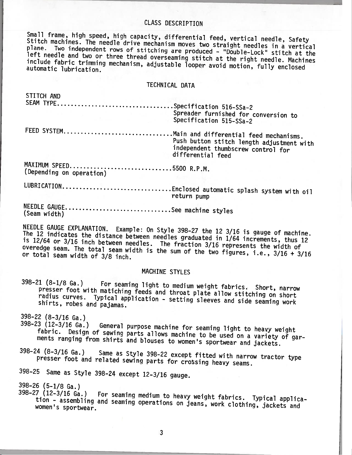
Small
Stitch
plane.
left
include
automatic
STITCH
SEAM
FEED
MAXIMUM
(Depending
frame,
machines.
Two
needle
fabric
lubrication.
AND
TYPE
SYSTEM
SPEED
on
LUBRICATION
high
speed,
The
independent
and
two
or
trimming
operation)
high
needle
rows
three
mechanism,
capacity,
drive
of
thread
mechanism
stitching
overseaming
adjustable
TECHNICAL
differential
moves
are
produced
looper
DATA
Specification
Spreader
Specification
Main
Push
independent
differential
5500
Enclosed
return
two
stitch
and
differential
button
R.P.M.
automatic
pump
feed,
straight
-
“Double-Lock”
at
avoid
516-SSa-2
furnished
515—SSa-2
stitch
thumbscrew
feed
vertical
the
motion,
for
length
splash
needles
right
feed
control
needle,
in
stitch
needle.
fully
conversion
mechanisms.
adjustment
system
Safety
a
vertical
at
Machines
enclosed
to
for
with
the
with
oil
NEEDLE
(Seam
NEEDLE
The
is
12/64
overedge
or
total
398-21
398-22
398-23
398-24
398-25
GAUGE
width)
GAUGE
12
indicates
(8-1/8
presser
radius
shirts,
(8-3/16
(12-3/16
fabric.
ments
(8-3/16
presser
Same
EXPLANATION.
the
or
3/16
seam.
seam
inch
The
width
Ga.)
foot
curves.
robes
Ga.)
Ga.)
Design
ranging
Ga.)
foot
as
and
Style
total
with
and
from
distance
between
of
3/8
For
matiching
Typical
pajamas.
General
of
sewing
shirts
Same
related
398—24
Example:
seam
inch.
seaming
application
as
except
between
needles.
width
feeds
purpose
parts
and
Style
sewing
On
Style
needles
The
is
the
MACHINE
light
to
and
-
machine
allows
blouses
398-22
parts
12—3/16
See
398-27
graduated
fraction
sum
of
STYLES
medium
throat
setting
for
machine
to
women’s
except
for
crossing
gauge.
machine
the
the
weight
plate
sleeves
seaming
to
fitted
styles
12
in
3/16
represents
two
figures,
fabrics.
allow
and
light
be
used
sportwear
with
heavy
3/16
1/64
stitching
seams.
is
gauge
increments,
i.e.,
side
seaming
to
heavy
on
a
variety
and
jackets.
narrow
the
Short,
tractor
of
width
3/16
on
weight
machine.
thus
of
+
narrow
short
work
of
gar
type
12
3/16
398-26
398-27
(5-1/8
(12-3/16
tion
-
women’s
Ga.)
Ga.)
assembling
sportwear.
For
and
seaming
seaming
medium
operations
to
heavy
on
weight
jeans,
3
fabrics.
work
clothing,
Typical
jackets
applica
and
Page 4
MACHINE
STYLES
(Continued)
398-28
398-29
NOTE:
stamped
is
machi
Saybolt
Union
between
sight
level
Clean
Oil
related
All
cutter.
Each
serial
The
ne.
Oil
viscosity
Special
Machine
tension
gauge
indicator
drain
To
magnetic
must
Same
sewing
Same
machine
UNION
the
in
capacity
Corporation
is
on
changed
be
Style
as
parts
Style
as
styles
SPECIAL
style
number
of
of
filled
disc
front
will
remove
oil
plug
398-27
for
398-21
listed
machine
plate
stamped
is
Class
90
support
of
register
of
periodically
398
125
to
Specification
with
machine.
magnetic
metallic
any
except
crossing
except
can
IDENTIFICATION
carries
located
is
seconds
at
oil
and
between
fitted
heavy
12-3/16
furnished
be
a
the
to
extension
on
LUBRICATION
eight
top
When
plug
to
ounces.
at
No.
spring
cover.
proper
red
on
material
minimize
with
seams.
OF
style
right
100
175.
cap
Before
gauge
back
that
wear.
tractor
gauge.
with
MACHINES
number,
rear
casting
of
Use
degrees
lines.
of
top
operating,
level
machine
may
under
oil
type
“AIR-KLIPP’
which
of
straight
a
F.
cover
is
have
on
machine.
right
at
This
or
reached,
near
accumulated
presser
vacuum
this
rear
mineral
equivalent
is
at
check
bottom
oil
red
class
oil
edge
foot
type
base
oil
filler
level
bulb
crankcase.
in
and
chain
machine
of
with
to
screw
at
oil
on
base.
of
a
Be
thread
five
Before
cloth
and
Turn
tweezers
in
aid
thread,
thread
looper
401
sure
machines
threading
plate
handwheel
No.
threading.
(2)
and
machine
401
(5)
machine
thread,
Thread
Thread
machine
out
in
660-272
looper
front
threaded
is
Fig.
or
machine;
position;
of
operating
and
sequence
in
thread,
needle
sequence
in
rear
(3)
1A,
unlock
direction
threading
thread.
needle
THREADING
properly
four
for
THREADING
presser
upper
pull
until
wire
shown
as
upper
(3)
Push
shown
as
thread
according
thread
DIAGRAMS
foot
looper
needles
39899
No.
Fig.
in
overedge
upper
Fig.
in
and
4
machines.
A
1;
looper
looper
1A;
front
(4)
threading
to
release
thread
are
are
(1)
(1)
bushing,swing
tube
highest
at
furnished
lower
thread,
thread
overedge
needle
diagram
for
up
with
overedge
(4)
tube
thread.
five
position.
machine
rear
down.
looper
Fig.
presser
threads.
looper
needle
thread,
for
1,
arm
Thread
to
(2)
Page 5
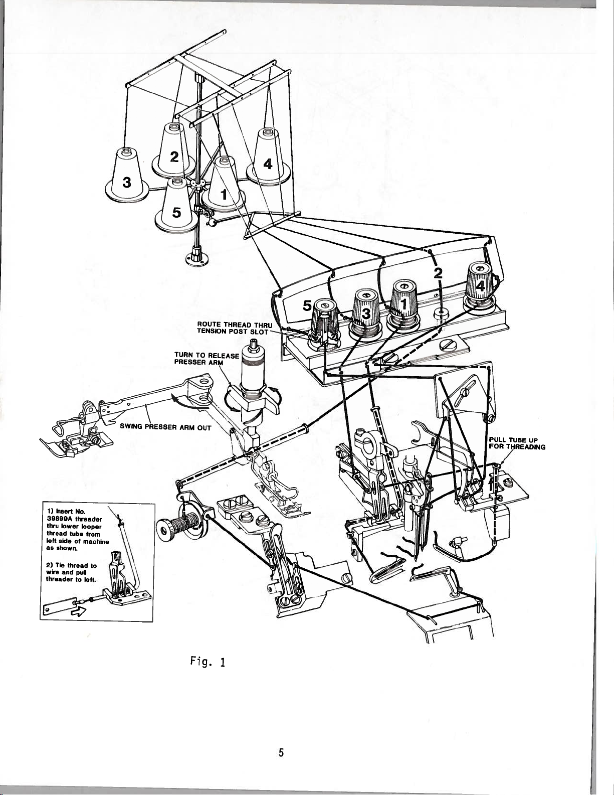
TUBE
UP
Fig.
1
5
Page 6
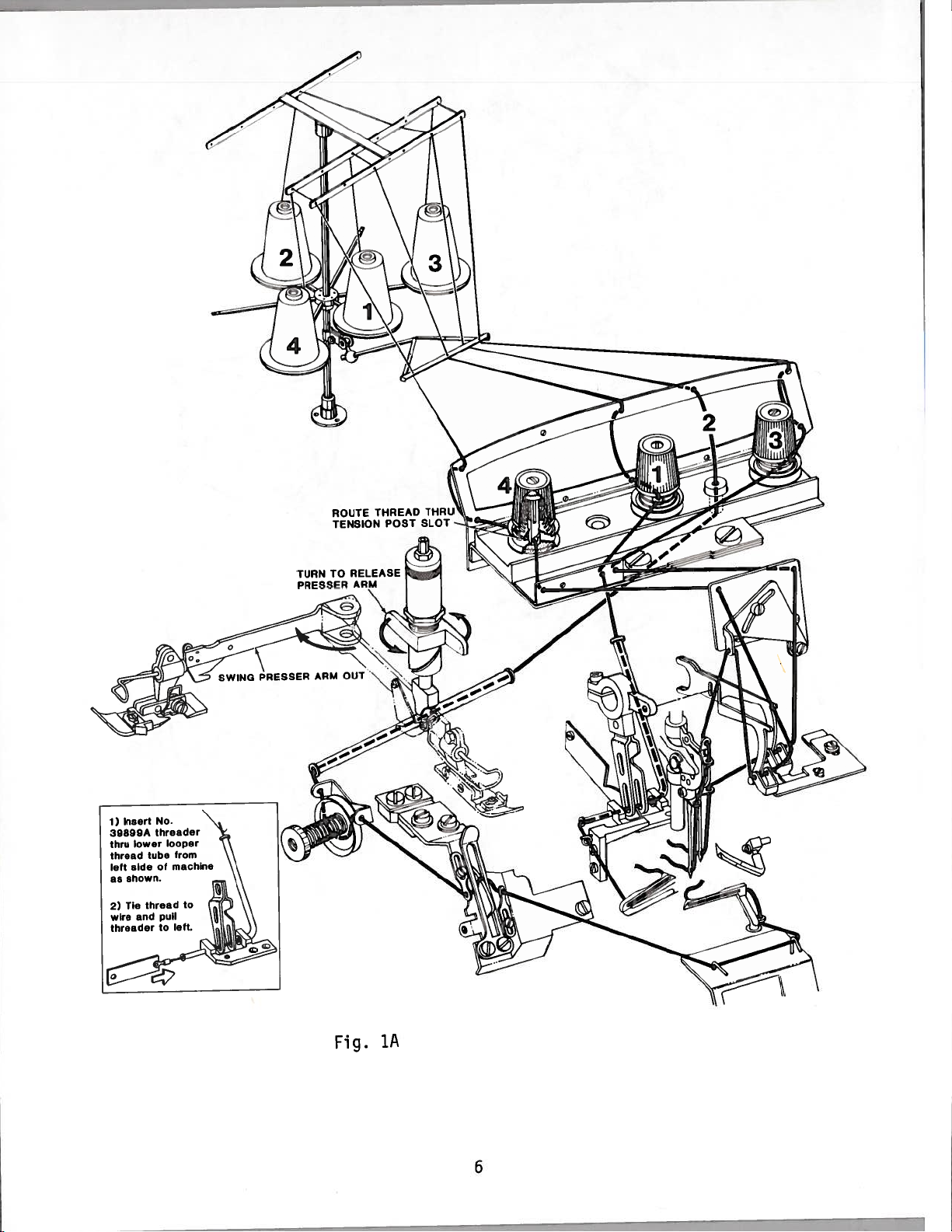
TURN
PRESSER
TO
RELEASE
ARM
1A
Fig.
6
Page 7
-
-
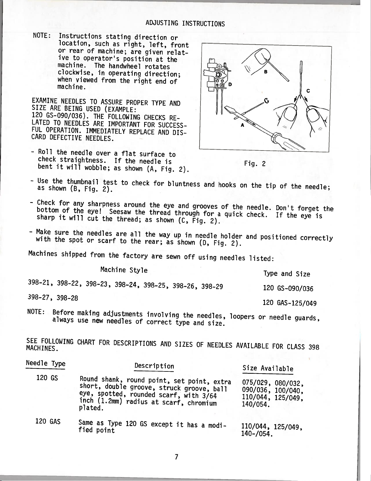
NOTE:
EXAMINE
SIZE
ARE
120
GS-090/036).
LATED
FUL
CARD
-
TO
OPERATION.
DEFECTIVE
Roll
the
check
bent
it
-
Use
the
as
shown
Instructions
location,
or
rear
ive
to
operator’s
machine.
clockwise,
when
viewed
machine.
NEEDLES
BEING
NEEDLES
needle
straightness.
will
thumbnail
(B,
stating
such
as
right,
of
machine;
position
The
handwheel
in
operating
from
the
TO
USED
THE
ARE
ASSURE
(EXAMPLE:
FOLLOWING
IMPORTANT
PROPER
IMMEDIATELY
NEEDLES.
over
wobble;
Fig.
test
2).
a
If
as
flat
the
shown
to
ADJUSTING
direction
left,
are
given
at
rotates
direction;
right
end
TYPE
CHECKS
FOR
REPLACE
surface
needle
(A,
check
for
iNSTRUCTIONS
or
front
relat
the
of
AND
RE
SUCCESS
AND
DIS
to
is
Fig.
2).
bluntness
and
hooks
on
Fig.
the
2
tip
of
the
needle;
-
Check
bottom
sharp
-
Make
with
sure
the
Machines
398-21,
398-27,
NOTE:
398-22,
398-28
Before
always
SEE
FOLLOWING
MACHINES.
Needle
120
Type
GS
for
any
of
the
it
will
the
spot
shipped
sharpness
eye!
cut
needles
or
from
398-23,
making
use
new
CHART
Round
short,
eye,
inch
plated.
around
Seesaw
the
thread;
are
scarf
the
to
factory
Machine
398-24,
adjustments
needles
FOR
DESCRIPTIONS
shank,
double
spotted,
(1.2mm)
the
as
all
the
the
rear;
Style
398-25,
of
Description
round
groove,
rounded
radius
the
eye
thread
shown
way
as
are
sewn
involving
correct
AND
point,
struck
scarf,
at
scarf,
and
through
(C,
up
in
shown
off
398-26,
the
type
SIZES
set
point,
groove,
with
chromium
grooves
for
Fig.
needle
(D,
using
398-29
needles,
and
size.
OF
NEEDLES
3/64
2).
Fig.
extra
ball
of
a
quick
holder
needles
loopers
the
2).
needle.
check.
and
positioned
listed:
Type
120
120
or
needle
AVAILABLE
Size
Available
075/029,
090/036,
110/044,
140/054.
Don’t
If
the
forget
eye
correctly
and
Size
GS-090/036
GAS-125/049
guards,
FOR
CLASS
080/032,
100/040,
125/049,
the
is
398
120
GAS
Same
fled
as
point
Type
120
GS
except
it
has
a
modi-
7
110/044,
140-/054.
125/049,
Page 8
Needle
Type
Description
Sizes
Available
120
120
120
GFS
GHS
GKS
Same
eye
Same
point.
Same
size
as
and
as
as
ball
Type
groove,
Type
Type
eye.
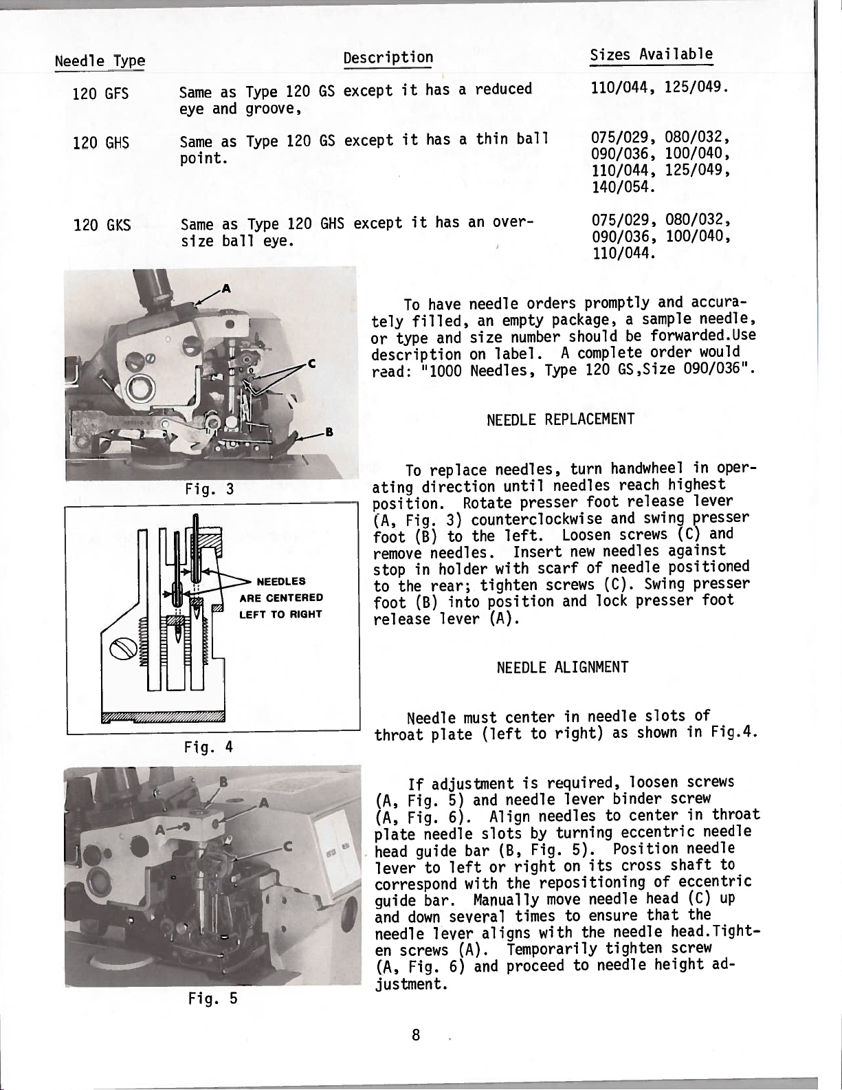
NEEDLES
CENTERED
ARE
TO
LEFT
120
120
120
RIGHT
GS
GS
GHS
except
except
except
tely
or
description
read:
ating
position.
(A,
foot
remove
stop
to
foot
release
it
it
it
To
filled,
type
To
Fig.
the
has
has
has
have
and
“1000
replace
direction
3)
to
(B)
needles.
holder
in
rear;
into
(B)
lever
reduced
a
ball
thin
a
over-
an
needle
an
size
on
orders
empty
number
label.
Needles,
NEEDLE
needles,
until
Rotate
presser
counterclockwise
left.
the
Insert
with
scarf
tighten
position
(A).
110/044,
075/029,
090/036,
110/044,
140/054.
075/029,
090/036,
110/044.
promptly
sample
120
a
be
GS,Size
package,
should
complete
A
Type
REPLACEMENT
handwheel
turn
foot
needles
of
(C).
lock
reach
release
and
screws
needle
presser
swing
Swing
needles
Loosen
new
screws
and
125/049.
080/032,
100/040,
125/049,
080/032,
100/040,
accura
and
needle,
forwarded.Use
order
would
090/036”.
oper
in
highest
lever
presser
and
(C)
against
positioned
presser
foot
Fig.
Fig.
ALIGNMENT
needle
in
right)
to
as
slots
shown
in
of
Fig.4.
throat
Needle
plate
must
NEEDLE
center
(left
4
screw
shaft
eccentric
of
head
that
head.Tight
screw
height
screws
throat
in
needle
needle
(C)
the
ad
to
up
—C
adjustment
If
Fig.
(A,
Fig.
(A,
plate
head
lever
needle
guide
to
correspond
guide
and
bar.
down
needle
en
screws
Fig.
(A,
5)
6).
left
several
lever
6)
and
Align
slots
bar
or
with
Manually
aligns
(A).
and
required,
is
needle
needles
turning
by
Fig.
(B,
right
repositioning
the
move
times
with
Temporarily
proceed
lever
5).
on
to
the
to
binder
to
Position
its
needle
ensure
needle
tighten
needle
loosen
center
eccentric
cross
justment.
5
8
Page 9
NEEDLE
HEIGHT
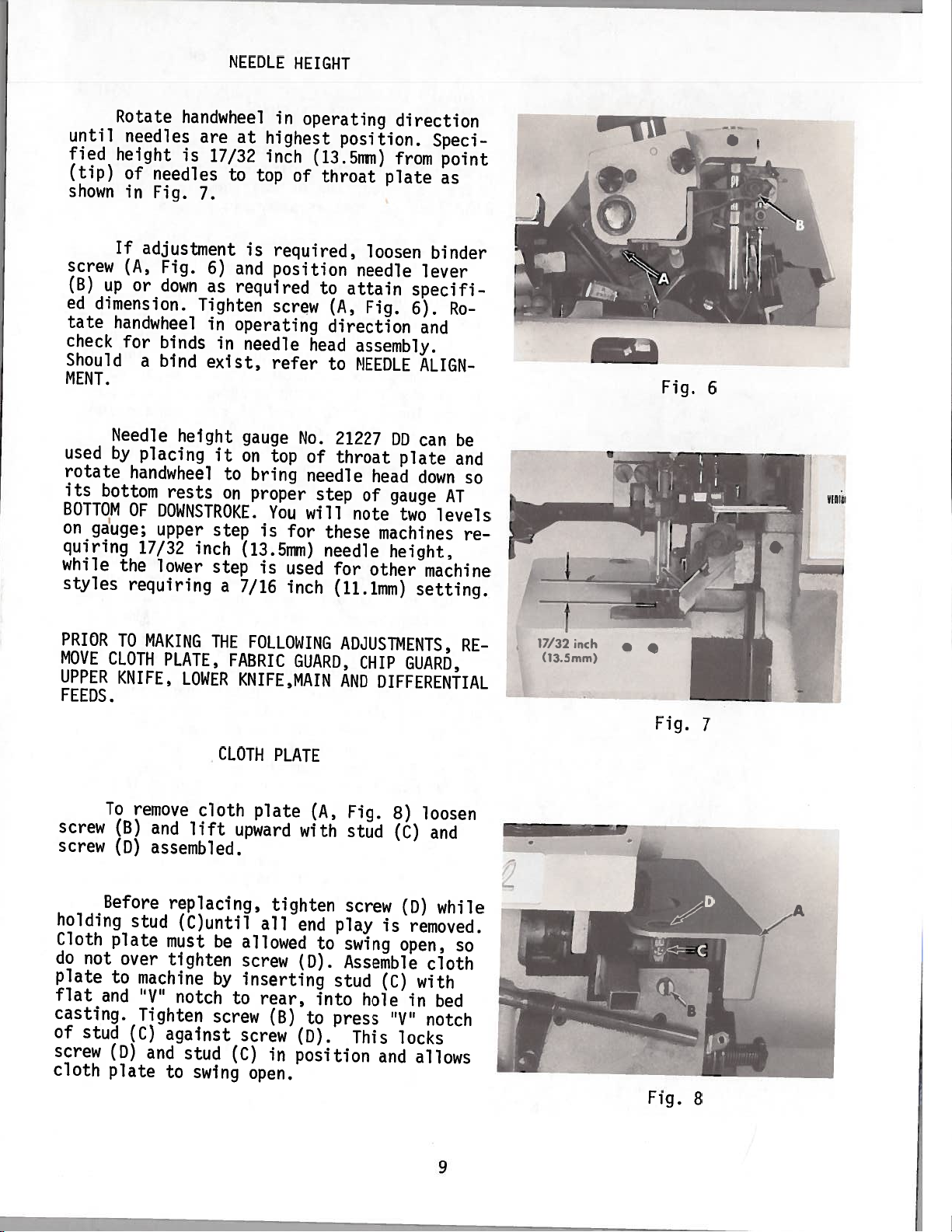
Rotate
until
fied
shown
screw
(B)
ed
tate
check
Should
MENT.
used
rotate
its
BOTTOM
on
quiring
while
styles
height
(tip)
If
up
dimension.
handwheel
Needle
by
bottom
gauge;
the
handwheel
needles
of
in
adjustment
(A,
or
for
a
placing
handwheel
OF
17/32
requiring
are
is
needles
Fig.
7.
Fig.
down
Tighten
binds
bind
height
rests
DOWNSTROKE.
upper
inch
lower
17/32
to
6)
as
in
in
exist,
it
to
on
step
step
a
in
at
highest
inch
top
is
required,
and
position
required
screw
operating
needle
refer
gauge
on
top
bring
proper
You
is
for
(13.5mm)
is
used
7/16
inch
operating
(13.5mm)
of
throat
to
(A,
direction
head
to
No.
21227
of
throat
needle
step
will
these
needle
for
(11.1mm)
position.
plate
loosen
needle
attain
Fig.
assembly.
NEEDLE
head
of
note
machines
other
direction
Speci
from
binder
lever
specifi
6).
and
ALIGN
DD
can
plate
down
gauge
two
height,
machine
setting.
point
as
Ro
be
and
so
AT
levels
re
Fig.
6
lTII
I
PRIOR
MOVE
UPPER
FEEDS.
screw
screw
holding
Cloth
do
not
plate
flat
casting.
of
stud
screw
cloth
TO
CLOTH
KNIFE,
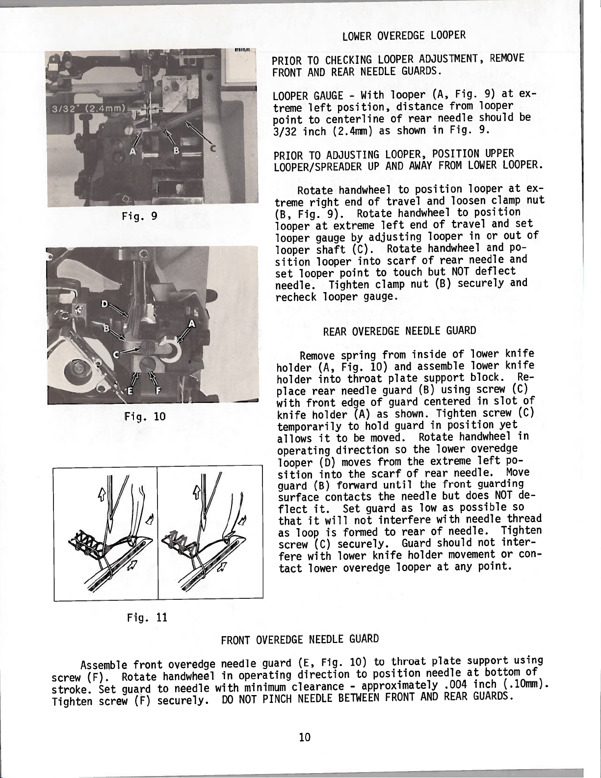
To
remove
(B)
(D)
Before
stud
plate
over
to
machine
and
“V’
Tighten
(C)
CD)
plate
MAKING
PLATE,
LOWER
cloth
and
lift
assembled.
replacing,
(C)until
must
tighten
notch
against
and
stud
to
swing
THE
FOLLOWING
FABRIC
KNIFE,MAIN
CLOTH
plate
upward
tighten
all
be
allowed
screw
by
inserting
to
rear,
screw
screw
(C)
open.
(B)
in
GUARD,
PLATE
(A,
with
end
to
(D).
into
to
(D).
position
ADJUSTMENTS,
CHIP
GUARD,
AND
DIFFERENTIAL
Fig.
stud
screw
play
swing
Assemble
stud
press
hole
This
8)
(C)
is
open,
(C)
“V’
locks
and
loosen
and
(D)
while
removed.
cloth
with
in
bed
notch
allows
RE
so
17/32
(13.5mm)
inch
•
1
•
Fig.
7
Fig.
8
9
Page 10
LOWER
OVEREDGE
LOOPER
Fig.
CHECKING
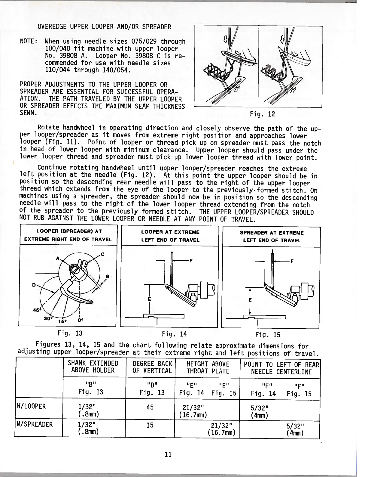
PRIOR
FRONT
LOOPER
treme
point
3/32
PRIOR
TO
REAR
AND
GAUGE
left
centerline
to
inch
(2.4mm)
ADJUSTING
TO
position,
LOOPER/SPREADER
right
at
gauge
shaft
looper
looper
handwheel
end
9).
extreme
point
Tighten
Rotate
treme
Fig.
9
(B,
looper
looper
looper
sition
looper
set
needle.
recheck
REAR
LOOPER
NEEDLE
With
-
as
LOOPER,
AND
UP
travel
of
Rotate
left
adjusting
by
into
Rotate
scarf
(C).
to
clamp
gauge.
OVEREDGE
ADJUSTMENT,
GUARDS.
looper
distance
rear
of
shown
AWAY
position
to
and
handwheel
end
looper
handwheel
of
touch
but
nut
NEEDLE
Fig.
(A,
from
needle
Fig.
in
POSITION
FROM
loosen
to
of
travel
rear
NOT
securely
(B)
GUARD
REMOVE
9)
looper
should
9.
UPPER
LOWER
looper
clamp
position
and
or
in
and
needle
deflect
at
ex
be
LOOPER.
ex
at
nut
set
of
out
po
and
and
Fig.
Fig.
10
11
Remove
holder
holder
place
with
knife
(A,
into
rear
front
holder
temporarily
allows
it
operating
looper
sition
guard
(B)
surface
flect
that
as
screw
fere
tact
it.
it
loop
(C)
with
lower
spring
Fig.
needle
edge
to
direction
moves
(D)
into
forward
contacts
Set
will
is
formed
securely.
lower
overedge
throat
(A)
hold
to
be
the
not
from
10)
guard
of
as
moved.
from
scarf
until
the
guard
interfere
to
knife
and
plate
guard
shown.
guard
so
the
of
needle
as
rear
Guard
looper
inside
assemble
support
(B)
centered
in
Rotate
the
extreme
rear
the
low
of
holder
of
using
Tighten
position
handwheel
lower
needle.
front
but
possible
as
with
needle.
should
movement
any
at
lower
lower
block.
screw
slot
in
screw
overedge
left
guarding
does
needle
not
point.
knife
knife
(C)
yet
po
Move
NOT
so
thread
Tighten
inter
or
Re
of
(C)
in
de
con
GUARD
Fig.
BETWEEN
10)
-
screw
stroke.
Tighten
Assemble
(F).
Set
screw
front
Rotate
guard
(F)
overedge
handwheel
to
needle
securely.
FRONT
needle
in
with
DO
OVEREDGE
guard
operating
minimum
PINCH
NOT
NEEDLE
(E,
direction
clearance
NEEDLE
10
throat
to
position
to
approximately
FRONT
plate
needle
AND
.004
REAR
support
at
bottom
inch
GUARDS.
using
of
(.10mm).
Page 11
OVEREDGE
UPPER
LOOPER
AND/OR
SPREADER
NOTE:
When
100/040
No.
commended
110/044
PROPER
ADJUSTMENTS
SPREADER
ATION.
OR
SPREADER
THE
SEWN.
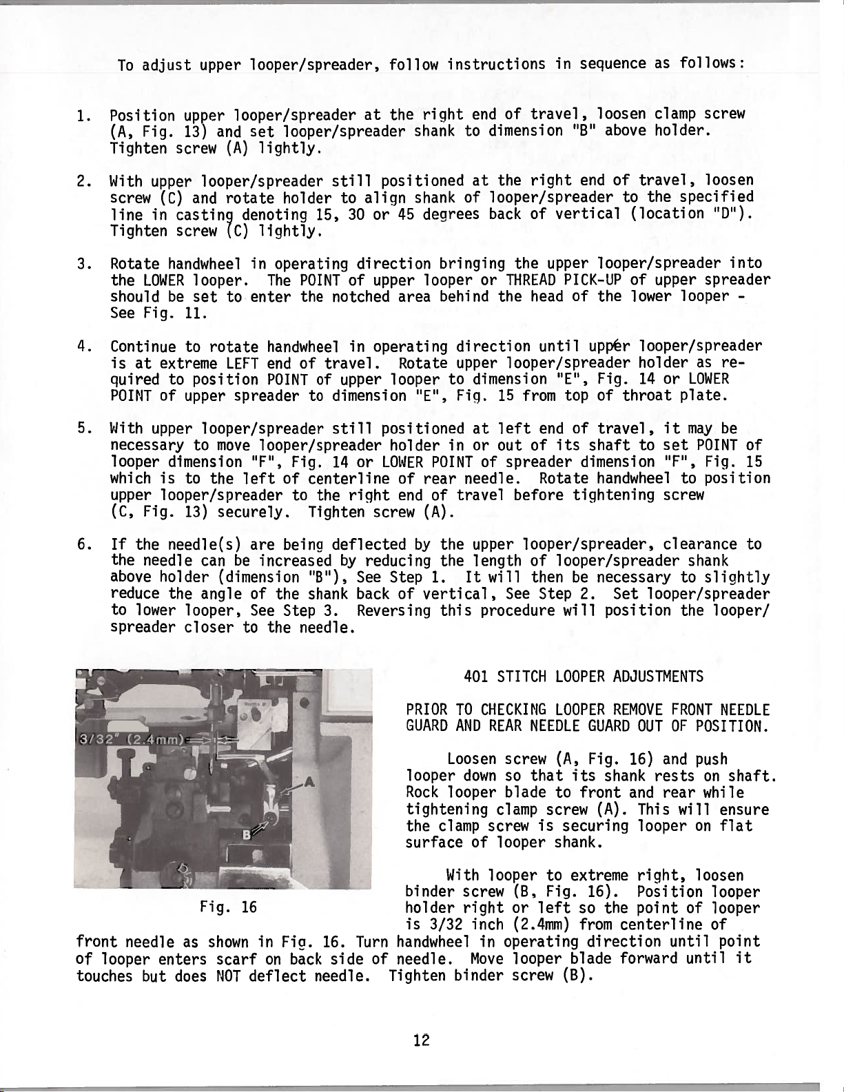
Rotate
per
looper/spreader
looper
in
lower
head
(Fig.
of
looper
Continue
left
position
position
thread
which
machines
needle
of
NOT
the
RUB
will
spreader
AGAINST
using
39808
ARE
ESSENTIAL
PATH
EFFECTS
handwheel
11).
lower
thread
so
the
extends
using
pass
needle
machine
fit
A.
for
through
TO
TRAVELED
Point
looper
rotating
at
the
descending
a
spreader,
to
to
the
THE
sizes
Looper
use
with
140/054.
THE
FOR
MAXIMUM
THE
in
operating
it
as
of
with
and
spreader
handwheel
needle
from
the
right
previously
LOWER
075/029
with
No.
upper
39808
needle
UPPER
LOOPER
SUCCESSFUL
BY
THE
UPPER
SEAM
direction
moves
looper
from
or
mininum
must
until
(Fig.
rear
the
the
12).
needle
eye
of
spreader
the
of
formed
LOOPER
OR
throuqh
looper
is
re
C
sizes
OR
OPERA
LOOPER
THICKNESS
extreme
thread
clearance.
pick
up
upper
this
At
will
the
pass
looper
should
lower
looper
stitch.
NEEDLE
AT
and
closely
right
pick
lower
position
up
Upper
looper
on
looper
looper/spreader
point
to
now
to
the
the
previouslyformed
the
in
be
thread
THE
UPPER
POINT
ANY
Fig.
observe
and
spreader
the
approaches
must
should
thread
with
reaches
upper
right
position
extending
of
looper
the
so
from
LOOPER/SPREADER
TRAVEL.
OF
12
path
pass
pass
lower
the
should
upper
the
the
of
the
lower
the
notch
under
the
point.
extreme
be
looper
stitch.
descending
notch
SHOULD
up
in
On
LOOPER
EXTREME
Figures
adjusting
(SPREADER)
RIGHT
Fig.
13,
upper
AT
END
OF
TRAVEL
13
14,
15
looper/spreader
SHANK
ABOVE
EXTENDED
HOLDER
‘‘B’’
Fig.
13
and
the
LOOPER
LEFT
chart
their
at
DEGREE
OF
VERTICAL
Fig.
AT
EXTREME
END
OF
Fig.
following
extreme
BACK
13
TRAVEL
14
relate
right
HEIGHT
THROAT
‘‘E’’
Fig.
14
approximate
and
left
ABOVE
PLATE
Fig.
15
SPREADER
LEFT
END
Fig.
dimensions
positions
POINT
NEEDLE
Fig.
EXTREME
AT
OF
TRAVEL
15
of
TO
LEFT
CENTERLINE
‘‘F’’
14
-F
Fig.
for
travel
OF
REAR
‘‘F’’
15
W/LOOPER
W/SPREADER
1/32”
(.8mm)
1/32”
(.8mm)
45
15
21/32”
(1.6.7mm)
21/32”
(16.7mm)
11
5/32”
(4mm)
5/32”
(4mm)
Page 12
To
adjust
upper
looper/spreader,
follow
instructions
in
sequence
as
follows:
1.
2.
3.
4.
5.
Position
Fig.
(A,
Tighten
With
upper
screw
line
in
Tighten
Rotate
LOWER
the
should
See
Fig.
Continue
is
at
quired
POINT
With
upper
necessary
looper
which
upper
Fig.
(C,
upper
13)
screw
looper/spreader
and
(A)
looper/spreader
and
(C)
castin9
screw
rotate
denoting
(C)
handwheel
looper.
be
set
to
11.
to
rotate
extreme
to
of
position
upper
LEFT
spreader
looper/spreader
to
move
dimension
is
to
the
left
looper/spreader
13)
securely.
set
looper/spreader
lightly.
holder
15,
liqhtly.
in
operating
The
POINT
enter
the
handwheel
of
end
POINT
travel.
of
to
looper/spreader
Fig.
“F”,
of
centerline
to
the
Tighten
at
to
30
positioned
align
or
still
direction
of
upper
notched
operating
in
upper
dimension
still
14
positioned
or
LOWER
right
screw
the
shank
shank
45
area
Rotate
looper
“E”,
holder
of
end
of
right
decirees
bringing
looper
behind
end
diniension
to
at
of
looper/spreader
back
or
travel,
the
right
of
the
THREAD
the
direction
upper
to
Fig.
in
looper/spreader
dimension
15
from
left
at
or
out
of
POINTofspreader
needle.
rear
of
travel
before
(A).
upper
head
until
end
Rotate
‘B’
end
vertical
PICK-UP
of
upp’ér
“E”,
top
of
its
shaft
dimension
tightening
loosen
above
of
to
clamp
holder.
travel,
the
specified
(location
looper/spreader
of
upper
the
lower
looper
looper/spreader
holder
Fig.
of
travel,
14
throat
to
or
plate.
it
set
“F”,
handwheel
to
screw
screw
loosen
“D”).
into
spreader
as
re
LOWER
may
be
POINT
Fig.
position
-
of
15
6.
If
the
above
reduce
to
spreader
front
needle
of looper
touches
the
needle
holder
lower
enters
but
needle(s)
can
the
angle
looper,
closer
Fig.
as
shown
does
are
be
increased
(dimension
of
See
the
to
16
in
scarf
NOT
on
deflect
beina
the
Step
Fig.
“B”),
shank
needle.
back
needle.
deflected
by
See
back
Reversing
3.
16.
Turn
side
reducing
Step
of
PRIOR
GUARD
looper
Rock
tightening
the
surface
binder
holder
is
handwheel
of
needle.
Tighten
by
the
the
1.
vertical,
this
TO
AND
Loosen
looper
clamp
With
3/32 inch
binder
upper
length
It
will
See
procedure
STITCH
401
CHECKING
REAR
screw
down
so
blade
clamp
screw
of
looper
looper
screw
right
(B,
or
(2.4mm)
in
operating
looper
Move
screw
looper/spreader,
of
looper/spreader
then
Step
NEEDLE
that
screw
is
necessary
be
2.
will
position
LOOPER
LOOPER
GUARD
(A,
Fig.
its
shank
to
front
(A).
securing
Set
ADJUSTMENTS
REMOVE
shank.
extreme
to
Fig.
left
so
16).
the
from
direction
blade
(B).
clearance
looper/spreader
the
FRONT
OF
OUT
and
16)
rests
and
rear
This
will
looper
right,
Position
point
centerline
until
forward
shank
to
slightly
looper!
NEEDLE
POSITION.
push
shaft.
on
while
ensure
on
flat
loosen
looper
of
looper
of
point
until
to
it
12
Page 13
ing
enters
(A,
passes
enters
thread,
around
termed
looper
left
travels
Fig.
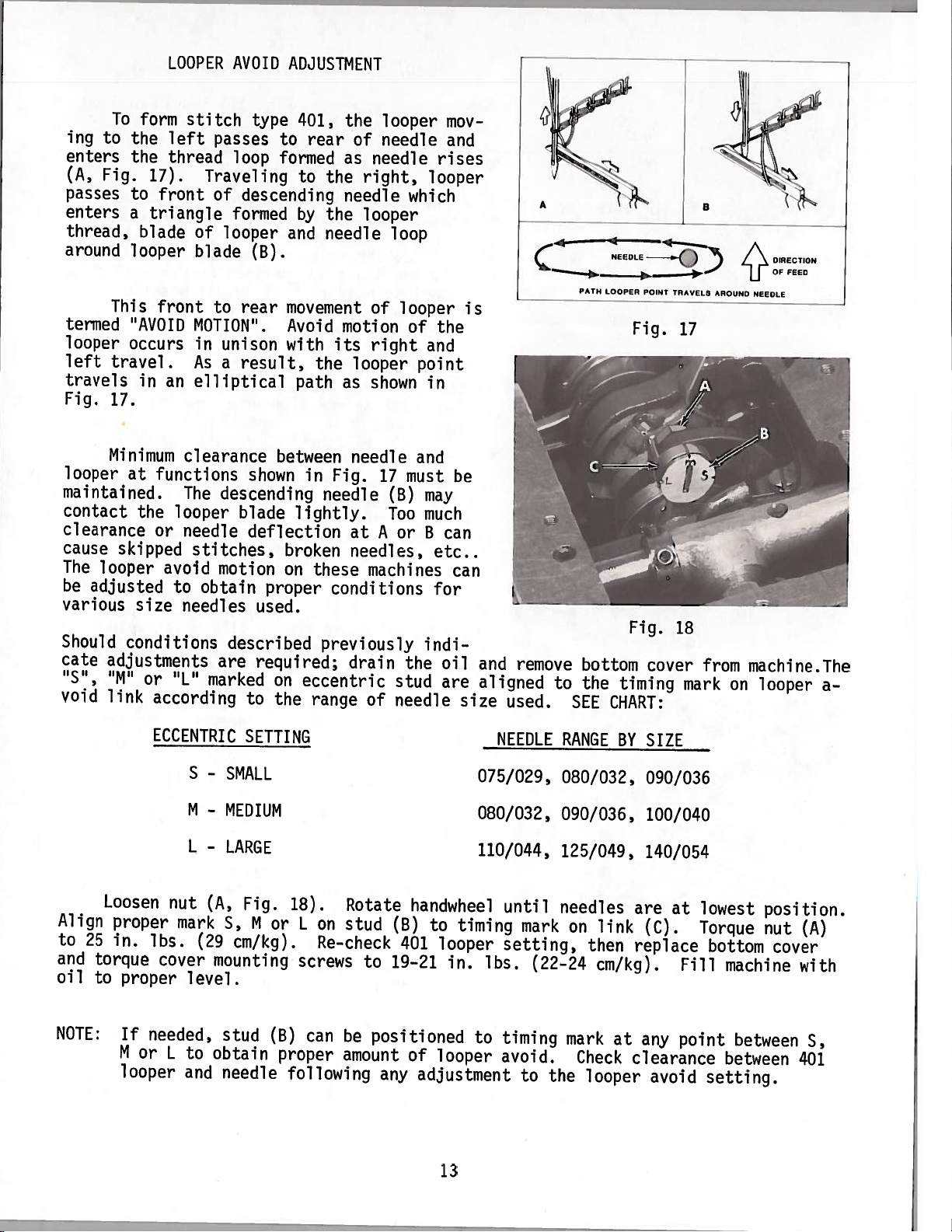
To
to
Fig.
This
occurs
travel.
17.
LOOPER
form
the
left
the
thread
17).
to
front
a
triangle
blade
looper
front
“AVOID
in
an
AVOID
stitch
passes
loop
Traveling
of
descending
formed
of
looper
blade
to
rear
MOTION”.
unison
in
a
As
result,
elliptical
ADJUSTMENT
type
401,
rear
to
formed
to
by
and
(B).
movement
Avoid
with
the
path
the
of
as
the
needle
the
needle
motion
its
looper
as
looper
needle
needle
right,
looper
loop
of
right
shown
looper
which
looper
of
and
point
in
mov
and
rises
the
C
PATH
NEEDLE
LOOPER
POINT
TRAVFLS
AROUND
NEEDLE
DIRECTION
OF
FEED
is
Fig.
17
Minimum
looper
maintained.
contact
clearance
cause
The
be
skipped
looper
adjusted
various
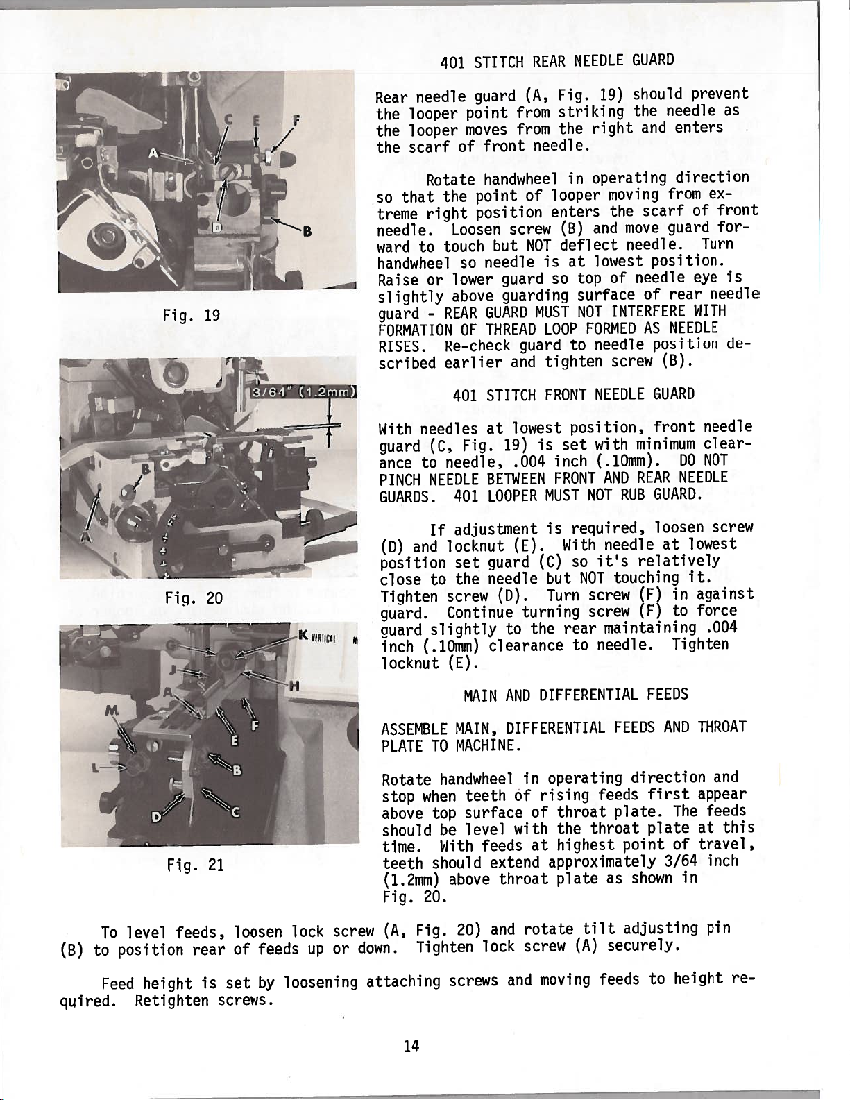
Should
cate
void
“S”,
adjustments
“M”
link
Loosen
Align
to
and
oil
25
torque
to
proper
in.
proper
clearance
at
functions
The
looper
the
or
needle
avoid
to
size
needles
conditions
or
“L”
according
ECCENTRIC
nut
mark
lbs.
cover
level.
descending
stitches,
motion
obtain
described
are
marked
S
-
SMALL
M
-
MEDIUM
L
-
LARGE
(A,
5,
(29
mounting
between
shown
blade
deflection
proper
used.
required;
on
to
the
SETTING
Fig.
M
or
cm/kg).
in
lightly.
broken
on
these
previously
eccentric
range
18).
L
on
Re-check
screws
needle
Fig.
17
needle
at
A
needles,
machines
conditions
drain
of
Rotate
stud
to
and
must
(B)
may
Too
much
B
or
indi
the
stud
needle
handwheel
(B)
401
19—21
be
can
etc..
can
for
oil
are
to
looper
in.
and
aligned
size
075/029,
080/032,
110/044,
timing
lbs.
remove
to
used.
NEEDLE
until
mark
setting,
(22—24
bottom
the
SEE
RANGE
080/032,
090/036,
125/049,
needles
link
on
then
cm/kg).
Fig.
cover
timing
CHART:
BY
SIZE
090/036
100/040
140/054
are
(C).
replace
18
mark
at
Fill
from
on
lowest
Torque
bottom
machine
machine.The
looper
a
position.
nut
(A)
cover
with
NOTE:
If
needed,
M
or
looper
stud
L
to
obtain
and
needle
(B)
can
proper
following
be
positioned
amount
any
of
looper
adjustment
to
timing
avoid.
to
the
13
mark
Check
looper
at
any
clearance
avoid
point
between
between
setting.
5,
401
Page 14
—
—
Fig.
19
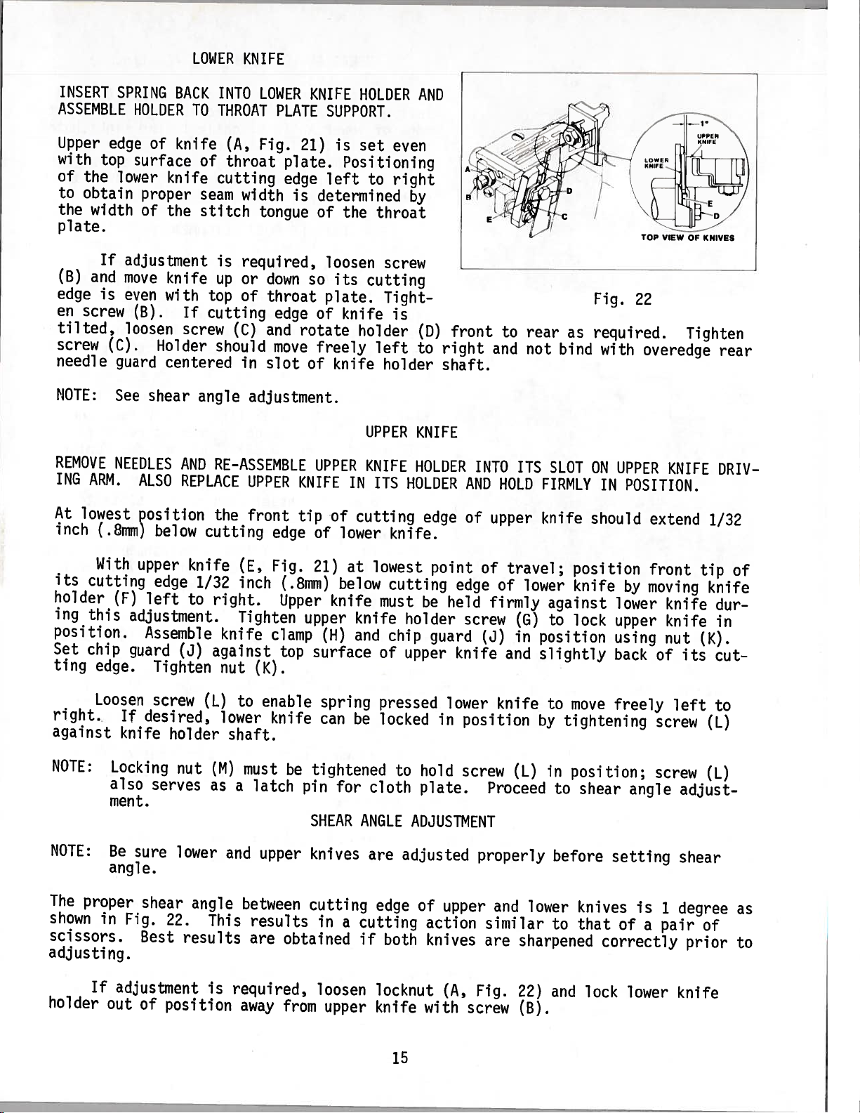
401
needle
Rear
looper
the
looper
the
scarf
the
Rotate
the
that
so
treme
needle.
ward
right
to
Loosen
touch
handwheel
lower
Raise
slightly
guard
or
-
above
REAR
FORMATION
RISES.
scribed
Re-check
earlier
401
With
needles
guard
ance
PINCH
(C,
to
NEEDLE
GUARDS.
needle,
401
STITCH
guard
point
moves
front
of
handwheel
point
position
but
needle
so
GUARD
THREAD
OF
STITCH
at
Fig.
BETWEEN
LOOPER
REAR
(A,
from
from
needle.
of
screw
NOT
is
guard
guarding
MUST
LOOP
guard
tighten
and
FRONT
lowest
is
19)
.004
MUST
NEEDLE
Fig.
striking
the
in
looper
enters
(B)
deflect
at
top
so
surface
NOT
FORMED
to
position,
set
inch
FRONT
NOT
GUARD
should
19)
the
right
and
operating
moving
scarf
the
move
and
needle.
lowest
needle
of
of
INTERFERE
AS
needle
screw
NEEDLE
minimum
with
(.10mm).
REAR
AND
RUB
prevent
needle
enters
direction
from
of
guard
position.
eye
rear
WITH
NEEDLE
position
(B).
GUARD
front
DO
NEEDLE
GUARD.
as
ex
front
for
Turn
is
needle
de
needle
clear
NOT
(B)
To
to
level
position
Fig.
feeds,
rear
21
loosen
of
feeds
lock
up
screw
or
(D)
position
close
Tighten
guard.
guard
inch
locknut
ASSEMBLE
PLATE
Rotate
stop
above
should
time.
teeth
(1.2mm)
Fig.
(A,
down.
If
locknut
and
to
screw
Continue
slightly
(.10mm)
TO
handwheel
when
top
be
With
should
20.
Fig.
Tighten
adjustment
guard
set
needle
the
CD).
to
clearance
(E).
AND
MAIN
MAIN,
DIFFERENTIAL
MACHINE.
teeth
surface
level
feeds
extend
20)
throat
and
above
lock
required,
is
(C)
but
With
so
NOT
(E).
Turn
turning
rear
the
to
DIFFERENTIAL
operating
in
rising
of
of
throat
at
the
highest
with
approximately
plate
rotate
screw
tilt
(A)
needle
relatively
it’s
touching
screw
screw
maintaining
needle.
FEEDS
direction
feeds
plate.
throat
point
shown
as
adjusting
securely.
loosen
at
(F)
(F)
FEEDS
AND
first
plate
3/64
lowest
it.
against
in
to
force
.004
Tighten
THROAT
appear
feeds
The
at
travel,
of
inch
in
pin
screw
and
this
screws
quired.
Feed
height
Retighten
is
screws.
set
loosening
by
attaching
14
and
moving
feeds
to
height
re
Page 15
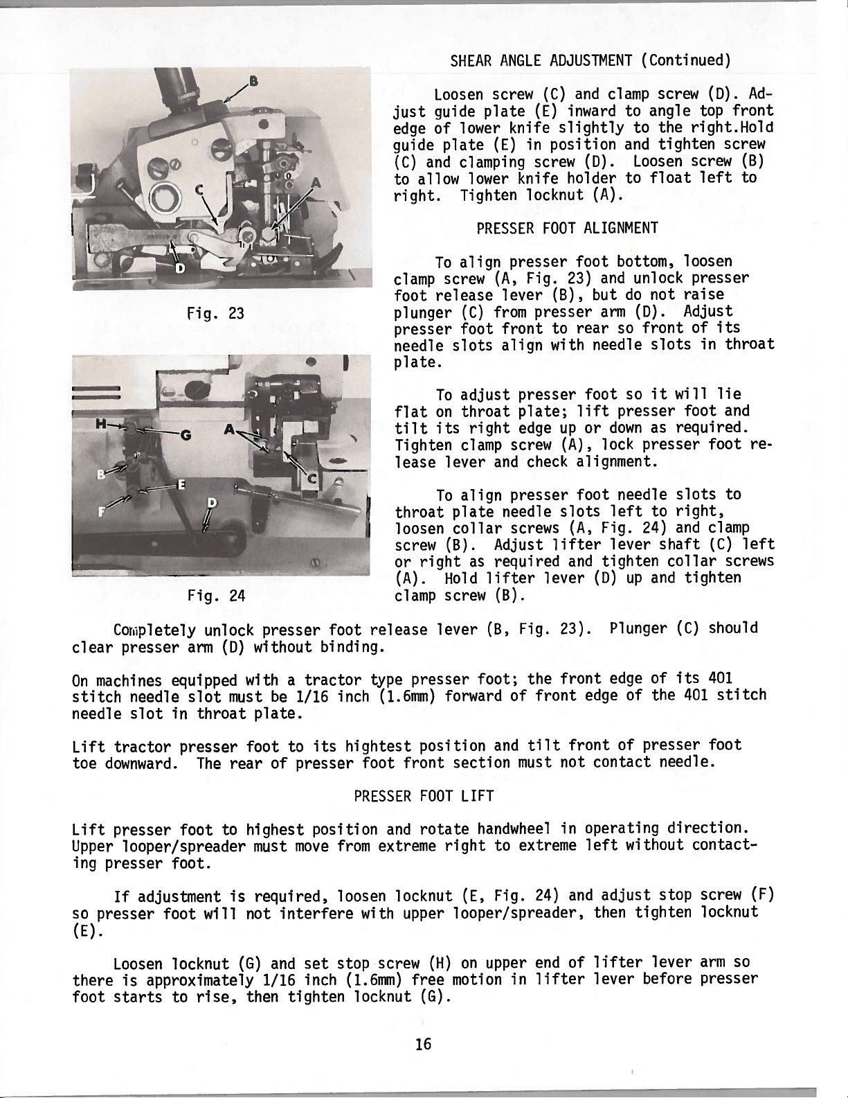
LOWER
KNIFE
INSERT
ASSEMBLE
Upper
with
of
to
the
plate.
(B)
edge
en
tilted,
screw
needle
NOTE:
REMOVE
ING
edge
top
the
obtain
width
If
and
is
screw
(C).
ARM.
SPRING
lower
adjustment
move
even
guard
See
NEEDLES
HOLDER
of
surface
knife
proper
of
the
knife
with
(B).
loosen
Holder
centered
shear
ALSO
BACK
knife
INTO
TO
THROAT
(A,
of
throat
cutting
seam
stitch
is
up
top
If
cutting
screw
AND
REPLACE
(C)
should
angle
RE-ASSEMBLE
LOWER
PLATE
Fig.
plate.
edge
width
required,
or
of
in
adjustment.
UPPER
is
tongue
down
throat
edge
and
move
slot
KNIFE
SUPPORT.
21)
is
left
determined
of
loosen
so
its
plate.
of
rotate
freely
of
knife
UPPER
KNIFE
HOLDER
set
even
Positioning
to
right
the
throat
screw
cutting
Tight-
knife
IN
is
holder
left
holder
UPPER
KNIFE
ITS
AND
by
(D)
front
right
to
shaft.
KNIFE
HOLDER
HOLDER
INTO
AND
to
and
ITS
HOLD
rear
not
bind
SLOT
FIRMLY
as
Fig.
22
required.
with
UPPER
ON
IN
POSITION.
Tighten
overedge
KNIFE
rear
DRIV
At
lowest
inch
its
holder
ing
position.
Set
ting
right.
against
NOTE:
NOTE:
The
shown
scissors.
adjusting.
(.8mm)
With
cutting
this
chip
edge.
Loosen
proper
(F)
adjustment.
guard
If
knife
Locking
also
ment.
Be
sure
angle.
in
Fig.
position
below
upper
edge
left
Assemble
(J)
Tighten
screw
desired,
holder
nut
serves
lower
shear
22.
Best
results
cutting
knife
1/32
to
CL)
angle
This
the
CE,
inch
right.
Tighten
knife
against
nut
to
lower
shaft.
(M)
must
as
a
and
between
front
edge
Fig.
clamp
(K).
enable
knife
latch
upper
results
are
tip
of
21)
(.8mm)
Upper
upper
top
surface
can
be
tightened
pin
SHEAR
knives
cutting
in
obtained
of
lower
at
below
knife
(H)
spring
for
a
cutting
knife.
lowest
cutting
must
knife
and
chip
of
pressed
be
locked
cloth
ANGLE
are
edge
cutting
if
both
edge
of
point
edge
be
held
holder
upper
to
hold
plate.
ADJUSTMENT
adjusted
of
guard
knife
lower
in
upper
action
knives
screw
position
screw
upper
travel;
of
of
firmly
(G)
(J)
in
and
knife
CL)
Proceed
properly
and
similar
are
sharpened
knife
lower
against
to
position
slightly
to
by
in
lower
should
position
knife
lock
move
tightening
position;
shear
to
before
knives
that
to
extend
front
by
moving
lower
upper
using
back
of
freely
screw
screw
angle
setting
is
of
a
correctly prior
knife
knife
nut
left
adjust
shear
degree
1
pair
tip
(K).
its
of
1/32
of
knife
dur
in
cut
to
CL)
(L)
as
to
If
holder
adjustment
out
of
position
is
required,
away
from
loosen
upper
locknut
knife
15
with
(A,
Fig.
screw
22)
(B).
and
lock
lower
knife
Page 16
just
edge
guide
(C)
to
right.
Loosen
guide
of
and
allow
SHEAR
lower
plate
clamping
lower
Tighten
ANGLE
screw
plate
knife
in
(E)
knife
locknut
PRESSER
ADJUSTMENT
clamp
and
(C)
inward
(E)
slightly
position
screw
FOOT
(D).
holder
(A).
ALIGNMENT
(Continued)
screw
to
angle
to
the
tighten
and
Loosen
float
to
(D).
top
front
right.Hold
screw
screw
left
(B)
to
Ad
clear
Corpletely
presser
Fig.
Fig.
arm
23
24
unlock
(D)
presser
without
foot
binding.
clamp
foot
plunger
presser
needle
plate.
flat
tilt
Tighten
lease
throat
loosen
screw
or
(A).
clamp
release
To
release
To
on
its
To
right
lever
align
screw
(C)
foot
slots
adjust
throat
right
clamp
lever
align
plate
collar
(B).
as
Hold
screw
presser
(A,
lever
from
front
align
presser
screw
and
presser
needle
screws
Adjust
required
lifter
(B).
(B,
Fig.
presser
plate;
edge
check
Fig.
23)
(B),
to
with
up
(A),
slots
lifter
and
lever
23).
but
foot
lift
or
foot
bottom,
and
arm
so
needle
presser
down
lock
needle
left
Fig.
lever
tighten
CD)
Plunger
foot
rear
alignment.
(A,
unlock
do
(D).
front
so
presser
24)
up
not
slots
it
as
to
shaft
collar
and
loosen
presser
raise
Adjust
its
of
in
will
lie
foot
required.
foot
slots
right,
clamp
and
(C)
tighten
should
(C)
throat
and
re
to
left
screws
machines
On
stitch
needle
Lift
toe
Lift
Upper
ing
so
presser
(E).
there
foot
equipped
needle
slot
in
tractor
downward.
presser
looper/spreader
presser
If
Loosen
is
starts
foot.
adjustment
foot
locknut
approximately
to
slot
throat
presser
The
foot
will
rise,
must
rear
to
is
with
plate.
foot
highest
must
required,
not
(G)
1/16
then
a
tractor
be
1/16
to
of
presser
move
interfere
and
set
inch
tighten
inch
hightest
its
position
from
loosen
stop
(1.6mm)
type
(1.6mm)
foot
PRESSER
with
locknut
front
and
extreme
locknut
upper
screw
presser
position
FOOT
rotate
(H)
free
(G).
16
and
to
Fig.
the
of
tilt
must
extreme
in
foot;
forward
section
LIFT
handwheel
right
(E,
looper/spreader,
upper
on
motion
front
24)
end
lifter
front
front
not
in
and
of
edge
of
edge
of
contact
operating
without
left
adjust
then
lifter
lever
of
the
presser
needle.
direction.
stop
tighten
lever
before
its
401
contact
401
stitch
foot
screw
locknut
arm
so
presser
(F)
Page 17
PRESSER
FOOT
PRESSURE
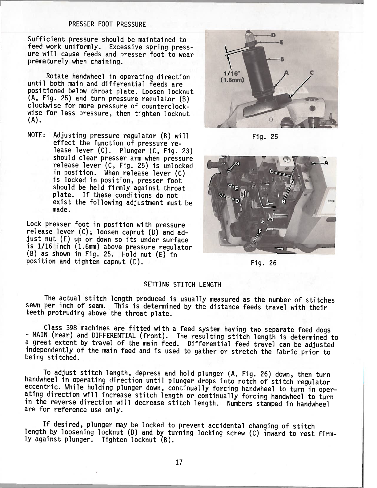
Sufficient
feed
work
ure
will
prematurely
Rotate
until
positioned
(A,
clockwise
wise
(A).
NOTE:
both
Fig.
for
Adjusting
effect
lease
should
release
in
is
should
plate.
exist
made.
pressure
uniformly.
cause
when
handwheel
main
below
25)
and
for
more
less
pressure,
the
lever
clear
position.
locked
be
the
feeds
chaining.
and
throat
turn
pressure
pressure
function
(C).
lever
in
held
If
these
following
should
Excessive
and
presser
in
operating
differential
plate.
pressure
then
regulator
Plunger
presser
Fig.
(C,
When
position,
release
firmly
conditions
adjustment
maintained
be
Loosen
reciulator
of
counterclock
tighten
of
pressure
arm
25)
presser
against
spring
foot
feeds
(C,
when
is
lever
do
press
to
direction
are
locknut
locknut
(B)
will
re
Fig.
pressure
unlocked
(C)
foot
throat
not
must
to
wear
(B)
23)
be
(1m)
D
E
\
Fig.
25
Lock
presser
release
just
is
1/16
(B)
position
sewn
teeth
-
MAIN
a
great
independently
being
handwheel
eccentric.
ating
in
the
are
nut
as
shown
The
per
protruding
Class
(rear)
extent
stitched.
adjust
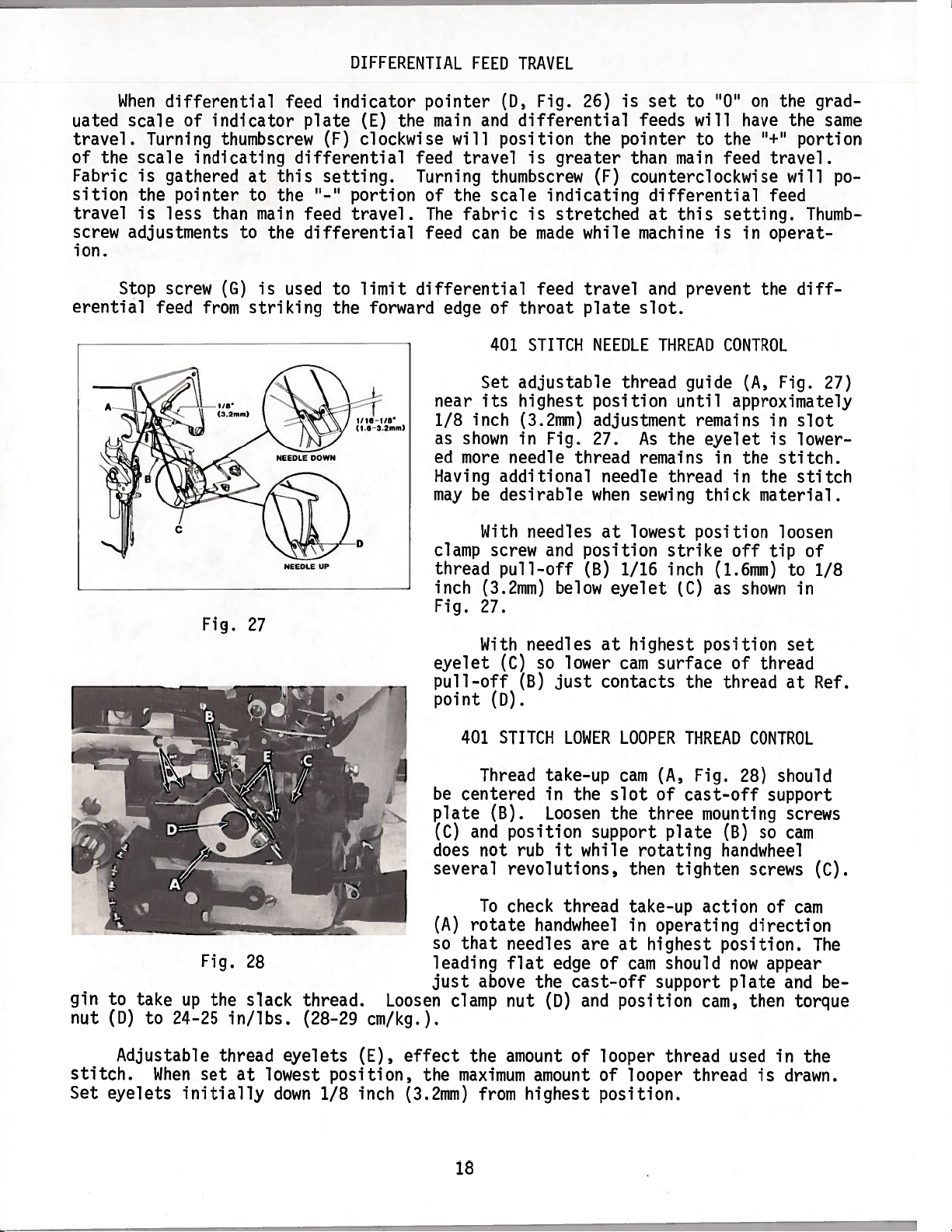
To
direction
reverse
for
reference
lever
inch
(E)
and
actual
inch
398
in
While
foot
up
(1.6mm)
in
tighten
operating
in
(C);
or
Fig.
stitch
of
seam.
above
machines
and
DIFFERENTIAL
by
travel
of
the
stitch
holding
will
direction
use
position
loosen
down
above
25.
capnut
main
length,
direction
increase
only.
capnut
so
Hold
length
This
the
are
of
feed
plunger
will
with
its
under
pressure
nut
CD).
produced
is
determined
throat
fitted
(front).
the
main
and
depress
stitch
decrease
pressure
CD)
and
surface
regulator
(E)
SETTING
plate.
with
feed.
is
used
and
until
down,
plunger
continually
length
stitch
ad
in
STITCH
is
usually
by
a
feed
The
to
hold
LENGTH
measured
the
distance
system
resulting
Differential
gather
plunger
drops
forcing
or
continually
length.
having
stitch
stretch
or
(A,
into
Numbers
Fig.
the
as
feeds
two
length
feed
travel
Fig.
notch
handwheel
forcing
26
number
travel
separate
the
26)
of
stitch
handwheel
stamped
is
can
fabric
down,
to
in
of
stitches
with
determined
turn
their
feed
dogs
be
adjusted
prior
then
turn
regulator
in
to
handwheel
to
to
oper
turn
If
length
ly
against
desired,
by
loosening
plunger.
plunger
locknut
Tighten
may
be
(B)
locknut
locked
and
by
to
turning
(B).
prevent
17
accidental
locking
screw
changing
(C)
inward
of
stitch
to
rest
firm
Page 18
_
uated
travel.
of the
Fabric
sition
travel
screw
ion.
erential
When
differential
scale
Turning
scale
is
gathered
the
pointer
is
less
adjustments
Stop
screw
feed
of
indicator
thumbscrew
indicatinq
than
(G)
from
at
to
main
to
the
is
striking
feed
plate
(F)
differential
this
setting.
“-“
the
feed
differential
used
DIFFERENTIAL
indicator
(E)
pointer
the
clockwise
feed
Turning
portion
travel.
of
The
feed
limit
to
the
differential
forward
FEED
main
will
travel
the
fabric
can
edge
near
inch
1/8
as
shown
ed
more
Having
may
be
TRAVEL
Fig.
CD,
and
differential
position
is
thumbscrew
scale
is
be
made
feed
of
throat
401
STITCH
Set
adjustable
its
highest
(3.2mm)
in
needle
additional
desirable
26)
the
greater
(F)
indicating
stretched
while
travel
plate
NEEDLE
position
adjustment
Fig.
27.
thread
needle
when
is
set
to
“0”
feeds
pointer
than
will
to
main
the
feed
counterclockwise
differential
this
at
machine
and
setting.
is
prevent
slot.
THREAD
thread
CONTROL
guide
until
remains
As
the
eyelet
remains
in
thread
sewing
thick
the
on
have
“+“
grad
the
portion
travel.
will
feed
Thumb
in
operat
the
diff
(A,
Fig.
approximately
in
slot
is
lower
the
stitch.
in
the
stitch
material.
same
po
27)
gin
nut
to
CD)
take
to
Fig.
up
24-25
Fig.
the
27
28
slack
in/lbs.
NEEDLL
thread.
(28-29
With
needles
(3.2mm)
27.
With
401
Thread
centered
and
not
To
rotate
that
above
clamp
screw
and
pull-off
needles
(C)
so
(B)
(D).
STITCH
take-up
in
(B).
Loosen
position
rub
revolutions,
check
handwheel
needles
flat
the
nut
(0)
it
edge
UP
thread
inch
Fig.
eyelet
pull-off
point
be
plate
(C)
does
several
(A)
so
leading
just
Loosen
clamp
position
(B)
below
lower
just
LOWER
the
support
while
thread
are
cast-off
and
at
lowest
1/16
eyelet
at
highest
cam
contacts
LOOPER
cam
slot
the
rotating
then
take-up
in
at
of
cam
position
strike
inch
(C)
surface
the
THREAD
(A,
of
cast-off
three
plate
tighten
operating
highest
should
support
position
off
(1.6mm)
shown
as
position
of
thread
Fig.
28)
mounting
(B)
handwheel
action
position.
now
plate
cam,
loosen
tip
of
to
1/8
in
set
thread
at
Ref.
CONTROL
should
support
screws
so
cam
screws
of
(C).
cam
direction
The
appear
and
then
torque
be
cm/kg.).
stitch.
Set
Adjustable
When
eyelets
thread
set
initially
at
eyelets
lowest
down
CE),
position,
inch
1/8
effect
the
(3.2mm)
the
amount
maximum
from
amount
highest
18
of
looper
of
looper
position.
thread
thread
used
is
in
drawn.
the
Page 19

OVEREDGE
NEEDLE
THREAD
CONTROL
With
screw
(A,
Fig.
face
of
below
thread
ines
or
FOUR
thread
With
eyelet
off
(A)
(D).
OVEREDGE
With
screw
the
to
(A,
looper
thread
Threading
through
of
looper
needles
securing
29)
its
the
centerline
eyelet
1/8
needles
(B)
so
barely
needles
Fig.
thread
tube
wire
thread
thread
needle
and
set
strike-off
holes
to
3/16
machines
at
the
lower
contacts
LOWER
at
30)
take-up
(C),
No.
tube
take-up
at
lowest
thread
the
tip
of
(B)
inch
-
Ref.
highest
thread
LOOPER
highest
and
center
then
39899
(C)
and
position,
cam
lower
1/32
overedge
on
FIVE
(3.2
point
position,
cam
surface
THREAD
position,
lower
(B)
front
tighten
A
should
the
-
Ref.
pull-off
extended
inch
needle
thread
to
4.8mm)
(C).
at
Ref.
CONTROL
screw
pass
lower
point
(.8mm)
of
slots
to
slots
(D).
loosen
sur
mach
on
set
pull-
point
loosen
of
back
(A).
freely
NEEDLES
L
Fig.
IN
HIGHEST
29
NEEOLES
UP
POSITION
9
-D
To
(E),
loosen
or
down
(G)
contacts
as
the
blade
reach
front
their
thread.barely
Ref.
point
tighten
With
take-up
back);
this
barely
(B).
thread
also
time,
contact
Reposition
in
set
until
needles
(H)
screw
needles
eyelet
set
the
the
the
screw
its
the
start
to
back,
lowest
contacts
on
(F).
(K)
auxiliary
upper
the
slot
lower
(F)
curved
lower
position
the
in
in
rear
eyelet
of
looper
and
position
section
looper
descending.
so
when
the
vertical
cast-off
OVEREDGE
highest
a
horizontal
thread
looper
thread
portion
(K)
if
take-up
cast-off
thread
the
the
lower
blade,
UPPER
position,
guide
of
necessary,
(B),
blade
-
Ref.
as
Position
needles
surface
position
should
the
then
blade
up
point
soon
looper
then
LOOPER
loosen
with
(L)
slightly
be
slot
in
(slightly
tighten
-
THREAD
screw
its
taut
left
screw
CONTROL
(J,
mounting
above
through
side
upward
(J).
Fig.
a
the
of
or
Fig.
30
30)
and
slot
horizontal
eyelet
looper
downward)
set
centered
position.
holes
thread
to
upper
(front
and
take-up
center
looper
to
At
should
19
Page 20

Fig.
31
BOTTOM
VIEW
If
properly,
set
result
as
adjustments
correct
Lower
-
Needle
-
Lower
-
rear.
the
Needle
-
If
of
edge
looper
erage
in
the
threads
of
Fig.
edge,
adjustments:
POSITIONING
needle
the
excessive
shown
which
condition
this
looper
thread
thread
looper
cast-off
thread
purl
the
fabric,
the
seamed
the
If
32.
check
thread
Fig.
in
should
strike-off
tension
is
NOT
an
indicated
is
edge
purl
the
the
THE
loop
seam
31.
be
include:
tension
blade
too
being
imbalance
would
is
following
PURL
grinning
Thread
checked
too
tip
too
loose.
formed
and
being
thread
NOT
is
tight.
low.
too
far
between
improper
occur
pulled
being
would
control
to
towards
on
as
control
the
the
cov
shown
under
Fig.
32
BOTTOM
*
TOP
VIEW
VIEW
Lower
-
Lower
-
the
Upper
-
the
Upper
-
edge
thread
Upper
-
Upper
-
rear.
Lower
-
Lower
-
rear.
front.
If
as
control
looper
looper
looper
looper
the
shown
looper
looper
looper
looper
thread
cast-off
thread
thread
in
is
Fig.
purl
adjustments:
thread
thread
cast-off
thread
too
eyelet
tension
being
33,
tension
eyelet
tension
tight.
blade
PULLED
check
blade
too
too
too
too
too
too
too
far
far
loose.
over
the
tight.
far
far
loose.
towards
towards
the
following
to
the
forward.
on
postal
The
type
Thread
threads
the
scale,
following
and
size
Fig.
tension
should
the
tensions
of
33
is
adjusted
only
be
measurements
are
thread
or
enough
are
starting
material
THREAD
and
taken
regulated
points
being
to
secure
TENSIONS
at
proper
with
the
only
sewn.
the
needles
and
may
20
tension
stitch
have
assemblies.
formation.
the
at
to
top
be
of
their
changed
Tension
Using
due
a
stroke.
to
Page 21

-
401
out
-
Overedge
straight
-
Overedge
straight
-
Overedge
straight
-
401
straight
needle
of
lower
lower
thread
needle
out
lower
out
upper
out
looper
out
eyelet
of
looper
of
looper
the
of
tension
thread
lower
thread
bottom
thread
eye
located
tension
eyelet
thread
tube
thread
at
point
THREAD
is
located
of
thread
tension
2
to
on
left
is
located
tension
tension
of
TENSION
2
1
tube
is
1
looper.
1/2
side
1/2
on
is
to
is
to
(Continued)
oz
of
to
2
right
to
1
rear
1
to
located
1
1/2
(57
needle
oz
side
1
of
1
oz
to
(43
1/2
throat
1/2
to
(28
71
head.
to
of
oz
oz
right
gr),
57
needle
(28
plate.
(28
to
of
43
to
gr),
to
to
upper
qr),
be
to
head.
43
43
measured
be
measured
gr),
gr),
to
to
knife
to
be
straight
be
measured
be
measured
driving
measured
arm.
The
is
derived
to
the
feed
segment
rocking
a
result,
erential
The
and
E)
feed
travel
travel
the
highest
position
feed
and
differential
The
regulator
to
produce
7
S.P.I.
the
differential
basic
from
individual
motion
any
feeds.
location
within
individually.
is
obtained
position
of
the
adjusted
adjustable
assembly
a
maximum
for
(C).
stitch
each
feed.
the
drive
stitch
by
link
by
main
feed.
motion
feed
Both
an
adjustable
length
of
the
segment
with
within
is
a
eccentric
(A)
stitch
feed
for
regulator
bars
by
segments
change
feed
drive
will
The
the
link
the
fixed
for
thumbscrew
within
is
set
at
length
and
INTERNAL
horizontal
assembly
means
are
of
affixed
eccentric
will
links
effect
longest
located
segment.This
the
main
for
the
stitch
the
factory
of
5
S.P.I.
FEED
the
within
effect
the
feed
at
for
ADJUSTMENTS
travel
(A,
main
to
Fig.
of
34).
feed
a
common
the
the
travel
(D
B
T
u
L
K
the
main
This
segment
shaft
stitch
c
D
regulator
of
both
S
and
motion
(B)
which
the
E
N
V
differential
is
transmitted
and
differential
is
driven
assembly.
main
H
A
and
feeds
in
diff—
G
/
a
As
obtained
and
Tighten
throat
the
slots.
duced,
located
for
this
plate
(B
and
Longer
turning
plate
If
then
Both
by
C).
feed
by
loosening
limit
screw
(F).
slots
necessary,
torque
at
the
adjustment.
main
following
travel
screw
left
and
for
inner
(G)
Rotate
making
repeat
limit
front
sure
procedure
screw
of
differential
instructions
both
feeds
lock
screw
counterclockwise.
handwheel
the
in
feeds
until
(G)
to
20
casting
feeds
below
can
listed
can
be
(F)
operating
do
desired
in.
the
be
in
sequence
not
contact
lbs.
upper
centered
direction
or
maximum
(23
cm/kg).
looper
front
for
adjusting
21
the
Fig.
and
front
stitch
An
thread
to
back
34
check
or
access
tube
feed
feed
rear
length
in
the
drive
ends
screw,
is
travel
of
is
pro
provided
throat
segments
in
Page 22

DIFFERENTIAL
button
push
Set
-
and
holding
ing
handwheel
FEED
in
operating
DRIVE
stitch
plunger
SEGMENT
regulator
down
(H)
direction.
(A,
in
Fig.
notch
34)
of
to
stitch
maximum
regulator
stitch
length
eccentric
by
and
depress
turning
Turn
-
pointer
Turn
-
of
pointer
Drain
-
Rotate
-
positioned
Loosen
-
Temporarily
be
repositioned
Manually
-
and
erential
the
to
operated
ting,
Replace
-
cm/kg),
differential
(K)
screw
stop
oil
and
handwheel
clamp
operate
bottom
feed
rear
and
then
bottom
then
is
positioned
(K).
remove
the
all
screw
tighten
segment
of
movement.
as
sliding
torque
fill
thumbscrew
counterclockwise
(M)
bottom
operating
in
way
(N)
screw
on
feed
pointer
slot.
required
block
clamp
cover
and
machine
to
and
drive
until
screw
at
cover.
the
position
(N)
(K)
Then
travels
torque
with
counterclockwise
(J)
bottom
the
as
direction
rear.
differential
hold
to
shaft
rock
down
and
up
this
At
gradually
differential
the
to
(N)
mounting
its
to
oil
of
required
until
segment
so
time,
tap
full
-
38
proper
graduated
the
for
(P)
sliding
while
the
feed
length
in.
40
screws
level.
until
to
differential
feed
position,
in
adjustment.
operating
top
shows
lbs.
scale
allow
block
-
of
to
differential
on
full
drive
yet
(R)
pointer,
front
movement
no
segment
-
(44
-
19
indicator
up
feed
segment
allowing
travels
section
slot.
cm/kg).
46
in.
21
and
dog
(C)
observe
of
when
lbs.
feed
plate
down
is
forward.
segment
to
segment
pointer
Recheck
(22
indicator
(L).
movement
top
the
diff
set
24
-
to
(C)
is
MAIN
Set
-
holding
wheel
Drain
-
Rotate
-
Loosen
-
Position
-
feed
of
no
(44
Set
-
nut
Replace
-
(22
If
-
by
position
DRIVE
FEED
button
push
plunger
in
operating
and
oil
handwheel
clamp
main
drive
main
feed
movement.
cm/kg).
46
-
CT)
feed
to
main
bottom
24
cm/kg),
-
necessary,
loosening
feeds
SEGMENT:
stitch
(H)
remove
screw
feed
CD)
link
dog
Recheck
drive
21
-
19
cover
further
locknuts
front
down
direction.
bottom
operating
in
CS)
drive
travels
teeth
link
in.
and
then
regulator
in
clamping
and
segment
centered
are
setting,
CD)
lbs.
torque
machine
fill
adjustment
then
(U),
back.
to
notch
cover.
direction
the
then
at
(22
(A)
of
(B)
full
the
24
-
its
can
rotating
Hold
maximum
to
stitch
until
CT).
nut
feed
on
length
the
in
torque
of
top
cm/kg).
mounting
be
oil
made
with
ferrules
regulator
needle
drive
of
slot
clamp
the
screws
to
to
eccentric
in
stitch
rock
segment
the
throat
of
screw
segment
proper
the
ferrules
position
length
eccentric
head
shaft
Cs)
slot
19
to
level.
main
is
plate
-
and
and
slot,
to
and
21
depressing
by
and
highest
at
so
(P)
the
and
-
38
torque
in.
differential
as
CV)
tighten
turning
when
middle
feed
in.
40
clamping
lbs.
required
locknuts.
and
hand-
position.
main
row
shows
lbs.
feeds
to
22
Page 23

DIFFERENTIAL
-
Rotate
and
pointer
an
clamp
differential
differential
(K)
adjustment is
screw
FEED
should
(i).
A
INDICATOR
feed
feeds
be
are
set
required,
POINTER
thumbscrew
equal.
to
‘O
on
loosen
(3,
At
the
clamp
FROM
Fig.
this
time,
graduated
screw
REGULATOR
34)
(W),
as
the
scale
set
required
differential
indicator
of
pointer
until
to
travel
feed
“0”
indicator
plate
and
TO
of
main
(L).
tighten
VENTURI
If
1.
2.
C
If
adjustment
cast-off
throat
Remove
(A,
Fig.
to
support
plate
support
“AIR-KLIPP”
35),
washer
the
‘AIR-KLIPP”
plate,
and
chain
plate
“AIR-KLIPP”
throat
rear
plate,
throat
cutter
(B)
and
Fig.
chain
plate
assembly
screw
35
CHAIN
cutter
401
looper
from
(C).
CUTTER
is
support
the
necessary;
take-up,
bracket.
machine
remove
take-up
removing
by
cloth
spacer,
screws
plate,
rear
With
CD)
together
maintaining
“AIR-KLIPP”
to
its
extreme
applying
a
slight
chain
right.
only
cutter
enough
shear
assembly
Loosen
pressure
angle,
screws
then
out
of
(E)
on
movable
tighten
machine;
and
press
screws
knife
23
position
air
to
(E).
tube
ensure
movable
(F)
and
proper
knife
base
cutting
(G)
Page 24

“AIR-KLIPP”
CHAIN
CUTTER
(Continued)
Re-assemble
3.
to
With
plate
(D,
ment
back
ure
the
machine
“AIR-KLIPP”
and
check
Fig.
36)
is
necessary,
on
“AIR—KLIPP”
as
outlined
Fig.
36
“AIR-KLIPP’
with
screws
chain
for
a
and
rear
loosen
chain
in
STEP
1I64
1164
chain
cutter
1/64
edge
2,
(.4mm)
(.4mm)
(A
inch
of
screws
cutter
then
cutter
C).
and
assembly
(.4mm)
throat
(E,
base
tighten
When
from
edge
the
extreme
must
stationary
adjust
To
and
(C)
quired.
screw
(C).
adjusted
strand
to
left
assembly,the
position,
in
clearance
plate
Fig.
as
(E),
35)
required.
screws
movable
be
movable
position
Hold
properly
thread
of
right.
main
between
as
and
(E).
left
even
knife
knife
Check,
feed
temporarily
shown.
adjust
Re-adjust
knife
to
with
Ref.
-
knife
knife
if
it
when
front
the
(A,
the
the
point
front
position
in
movable
will
manually
and
edge
If
a
air
movable
Fig.
right;
cutting
(A),
loosen
to
cut
plate
replace
of
clearance
tube
36)
its
B.
back
and
knife
single
a
moving
(B,
throat
air
(F)
knife
travels
cutting
edge
screw
as
tighten
(A)
Fig.
tube
adjust
front
press
of
re
is
knife
35)
to
Before
ter
NOTE:
With
treme
to
knife
and
screw
4.
To
permit
button
start
base
Main
ing
main
right;
extend
as
the
(C).
adjust
sewing,
tightening
is
set
stitch
the
following adjustment.
stitch
less
no
shown
inner
the
acuator
is
fully
flush
length
length
loosen
in
wall
air
block
extended,
the
mounting
against
determines
screw
than
Fig.
of
1/64
36.
air
valve
(K)
air
valve
screws
set
and
(C)
inch.
Clearance
tube
system,
to
just
then
must
the
movable
and
Ref.
-
loosen
contact
tighten
open
sure
be
main
feed
movable
adjust
(.4mm)
must
Point
screws
screws
before
the
knife
knife
movable
beyond
be
button
right
bar.
travel
(A,
the
maintained
F.
Hold
(H,
of
(H).
the
clutch
side
Tighten
Fig.
knife
cutting
knife
Fig.
air
When
of
and
36)
left
between
35)
valve
treadle
is
“AIR-KLIPP”
screws
must
(A
be
positioned
right
to
of
edge
the
position
in
set
and
-
Ref.
is
engaged.
chain
C).
and
set
before
to
as
stationary
moving
and
collar
point
pressed
cut
mak
its
ex
required
knife
tighten
to
(J)
when
L,
to
24
Page 25

“AIR-KLIPP”
CHAIN CUTTER
(Continued)
Replace
5.
verse
direction
est
To
set
(A,
cam
llel
(B)
To
center
cast-off
adjust
required,
times
PRIOR
TO
BOTTOM
1.
Remove
spacer
to
crankshaft.
parts
manner.
until
position.
401
looper
Fig.
37),
take-up
with
to
24
so
cast-off
-
25
cam
plate
cast-off
then
to
check
CRANKSHAFT
COVERS.
nut
(A,
(D).
Loosen
removed
Turn
handwheel
the
thread
loosen
its
longest
plate
in/lbs.
take-up
loosen
(C)
plate
tighten
for
binding.
REMOVAL:
Fig.
in
needles
nut
(28—29
(A)
left
screws.
38),
screws
STEP1in
in
operating
are
at
take-up
cam
and
Torque
position
is
(B)
flat
(C).
cm/kg).
in
slot
of
screws
to
(D)
right
Rotate
CRANKSHAFT
DRAIN
washer
F,Gand
E,
OIL
(B),
a
re
high
para
nut
and
as
handwheel
REMOVAL
REMOVE
AND
401
H
looper
securing
operating
in
THROAT
thread
stitch
PLATE
take-up
regulator
Fig.
AND
37
direction
BOTH
and
(C)
several
TOP
AND
take-up
assembly
(J)
NOTE:
NOTE:
2.
IMPORTANT:
Tension
shaft
To
Remove
removal.
re-assemble
four
Mark
counterweights
3.
Remove
oil
crankshaft.
IMPORTANT:
During
rods
the
4.
Remove
slide
inner
out
with
5. Loosen clamp
driving
removal.
lever
Remove
crankshaft.
spring
screws
counterweights
tube
(N)
re-assembly,
and
bearing
left
end
crankshaft
crankshaft.
(A,
nut
drops
(C)
two
(K)
stitch
(L)
and
of
Fig.
screws
may
drop
regulator
and
counterweights
and
during
all
connecting
be
caps
machine.
bearing
39).
off
arm
(E)
stitch
of
out
assembly
crankshaft
re-assembly.
rod
trademarks
sure
positioned
are
stud
Slide
(B)
and
(U),
upper
allowing
bearing
regulator
(J),
(M).
cheeks
bearing
on
to allow
knife
bearing
(D)-Ref.
cap
SEE
for
caps
stamped
the
inner
driving
cap
STEP
correct
same
assembly
NO.
points
at
on
both
side
crankshaft
arm
(B)
to
(D)
point
during
(J)
12.
positioning
R,
P,
S
the connecting
and
face
towards
bearing
the
to
be
(W,
left
positioned
Fig.
38)
crank
of
andTon
(V)
to
until
for
on
6.
7.
8.
Remove
Loosen
Remove
screw
two
three
(X)
screws
screws
and
(z)
take
and
(AB),
off
pulley
slide
bearing
belt
plate
cap
pulley
(AC),
(Y).
off crankshaft.
(AA)
spacer
25
collars
AD
and
AE.
Page 26

AF
AE
AC
Y
x
Fig.
38
9.
Remove
With
bearing
shaft
shaft.
NOTE:
needle
crankshaft
can
When
washer
(AF)
use
flange
pressing
(AH).
driving
out
an
(AG),
a
of
arbor
new
lever
machine,
press.
thrust
bearing
connecting
check
Only
washer
onto
rod
ball
after
(AH)
crankshaft,
26
and
bearing
bearing
and
withdraw
bearing
be
(AF)
sure
crankshaft
for
(AF)
CV)
it
wear.
is
be
seats
pressed
removed
against
from
To
off
from
machine.
remove
crank
crank
thrust
Page 27

PRIOR
CLEAN
10.
TO
MACHINE.
To
re-assemble
outlined
During
for
proper
shaft.
ly during
ing
occurs.
11.
In
order
assembly
tool
tool
tor
assembly
slot
tioned
Thread
crankshaft
unscrew
gulator
shaft,
rection
regulator
ing
groove
Fig.
CE,
spot
wheel
ble,
(F).
limiting
ADJUSTMENT.
RE-ASSEMBLING
crankshaft,
removal
for
re-assembly,
positions
Rotate
pulley
re-assembly
to
re-assemble
(J)
correctly
No.
(A,
slips
in
tool
21270
Fig.
stitch
into
onto
OP
40)
and
is
through
rotate
tension
regulator
crankshaft
through
and
remove
assembly
turn
until
positioned
handwheel
first
assembly
on
crankshaft
38),
then
screw
until
then
To
(E);
hole
insert
secure
screw
continue
for
and
inner
(H)
CRANKSHAFT,
follow
in
reverse
a
check
of
cap
to
exploded
parts
(Y)
be
on
periodical
sure
stitch
on
crankshaft,
required.
stitch
tool
until
spring
mechanism.
and
stitch
tool.
regulator,then
With
stitch
on
in
operating
screw
(J)
insert
screw
tighten
-
SEE
hole
aligns
for
and
to
lock
screw
INTERNAL
with
spot
tighten
rotate
(F)
set
THOROUGHLY
steps
manner.
views
crank
no
bind
regulator
Slide
regula
its
(B)
posi
slide
re
crank
di
of
stitch
tim
screw
hand-
is
visi
screw
(G)
and
FEED
Fig.
Fig.
39
40
27
Page 28

9z
Page 29

-a-.m...
MAIN
FRAME,
—
MISCELLANEOUS
COV[RS,
PLATES
ANI)
BUSUI
NGS
Ref.
No.
2
3
4
5
6
7
O
O
18
11
12
13
14
15
16
17
18
10
20
21
22
23
24
25
26
27
28
29
30
31
32
33
34
35
36
37
38
39
40
41
42
43
44
45
46
47
48
49
50
51
52
53
54
55
56
57
58
59
60
61
62
63
64
65
66
67
Port
No.
22894
39002
22541
39002
39082
39894
22569
39094
CL21
22565
39852
39893
88
39849
39849
22804
15037
22560
30501
30855
30573
30573
30544
643-400
39536
22894
39836
39578
22657
39501
39501
39782
30593
666-271
660—506
56393
56393
666-280
39593
39595
39782
39782
39893
P1-18
39893
660-645
39893
22806
22541
39882
39593
22586
22569
39593
39893
666—268
90
39B32
138
22569
39834
39890
22539
39844
39582
39644
22653
AG
R
B
P
F
C
D
0
M
C
C
F
AK
A
K
D
K
AA
X
BY
Y
Y
F
D—12
DX
DY
A
K
8
V
LI
B
8
F
D
A
B
5
C
T
D
D
E
8
0
F
K
E
F
C
0—4
Blk
ter
for
Cover
for
for
ic
1
for
Collector
Wick
Screw
Lever
Filler
for
Length
Length
for
for cloth
Plate
Lifter
Knife
Knife
Looper
Tube
Screw,
Plate
for
Plate,
Plate,
Cover
Tube,
Tube,
Filter,
for
Tube,
Pump
Cover
Filter
Pin
Oil
Oil
Tube
for
for
Cover
Gauge
for
for
Gauge
for
Pad
for
Plate
for
for
Screw
Looper
Plate
Looper
for
Filter
Tube
Filter
Pump
Spacer
Screw,
Top
Screw,
Upper Oil
Gasket,
Metol
Screw,
Oil
Oil
Plug
Needle
Oil
Screw,
Stitch
Stitch
Screw,
Nut
Screw,
Cloth
Foot
Upper
Upper
Lower
Oil
Differential
Plug
Differential
Cloth
Screw,
Cloth
Cloth
Bottom
Oil
Oil
Retaining
Porex
Spring,
Oil
Oil
Isolator
Bottom Cover
Bottom
Porex
Oil
Screw,
Screw,
Bottom
Oil
Screw,
Screw,
Oil
Spring,
Felt
Screw,
Cloth
Screw,
Screw,
Differential
Crankshaft
Plug
401
Base
oi
Screw,
cover
top
upper
Shield
upper
collector
oil
Drive
Screw
system
oil
Regulator
Regulator
sti
tch
Stud
Shaft
On
vi
Driving
Bar
Feed
for
Feed
Fabric
cloth
for
for
tygothane
brass
Ring,
for oil
oil
tygothane
Plate
Plate
Sleeve
Tube
bottom
bottom
Gasket
Float
bottom
oil
tube
Indicator
oil
cloth
Latch
cloth
feed
Feed Bar
Bearing,
Drive
Extension
Drive
base
P1J±LPfl
oil
Cover
oil
Shaft
Assembly
length
plate
Bushing
ng
Arm
Arm
Bushing
Rocker
bed
Rock
Guard,
plate
machines
machines
for
oil
tube
Gasket
cover
cover
cover
spring
tube
plate
Spring
plate
bar
thrust
inner
Shaft
Shaft
plate
shield
shield
Bushing
Return
regulator
stud
Bushing,
Bushing,
Shaft
Shaft
tube
tube
latch
fabric
Thrust
Bushing,
Bushing,
extension
cover
cover
Bushing
for
without
with
spring
washer
Washer
left
machines
guard
Spring
left
right
Bushing
without
“AIR-KLTPP”
“AIR—KLIPP”
left
right
“AIR—KLIPP”
chain
chain
cutter
cutter
chain
cut
As
Aint.
Reib
2
1
12
1
1
1
1
1
Req.
1
4
1
2
1
1
1
1
1
1
2
1
1
1
1
1
1
2
1
1
1
1
1
1
1
1
1
1
1
1
4
1
1
1
1
1
1
1
1
17
1
1
1
1
1
1
1
2
1
2
2
1
1
1
1
1
1
2
29
Page 30

DC
Page 31

CRANKSHAFT
MECHANISM
10
1].
12
13
14
15
16
17
18
19
20
21
22
23
24
25
26
27
28
29
30
Ref.
No.
1
2
3
4
5
6
7
8
9
-
-
Part
No.
39690
39890
660-443
39590
39590
660-268
39590
39590
39590
22569
39521
95
39821
22769
29477
39852
A
B
MK
A
77
22587
M
39516-625
39516-626
39516-627
30-106
51—569
C067
E
40-46
258
39890
E
97A
39691
39593
39591
22747
J
K
B
A
C
J
G
R
5
H
B
GA
Stud,
Crankshaft
“0”
Thrust
Crankshaft
Crankshaft
Ball
Spacer
Crankshaft
Screw,
Pulley
Pulley
Screw,
Crankshaft
Blk.
Blk.
Split
Crankshaft
Oil
Crankshaft
Screw,
for
Ring,
Bearing
Screw,
Needle
Needle
Needle
Needle
Wood
Vent
Cork
Washer
Nut
Bearing
Screw,
Pump
for
crankshaft
Bearing,
for
Washer
Ball
Ball
Stop
Collar
Ball
for
ball
for
Cap
for
pulley
and
Driving
Screw
Screw
Bearing,
Bearing,
Bearing,
Plug,
Plug
Plug
and
for
Counterweight,
Tube
Counterweight,
crankshaft
Description
inner
crankshaft
Bearing
Bearing
Collar
Bearing
bearing
pulley
cap
Needle
Connecting
birch
Oil
split
bearing
right
bearing,
Housing
Retaining
retaining
Driving
.0625
.0626
.0627
Connecting
inch
inch
inch
Pump
bearing
and
right
left
counterweight
Rod
(1.588
(1.590
(1.593
oil
inner
Plate
plate
Assembly
mm)
mm)
mm)
pump
right
and
Rod
housing
Assembly
diameter
diameter
diameter
Amt.
Req.
1
1
1
1
1
1
1
1
1
3
1
2
1
1
1
1
1
2
28
28
28
1
1
1
1
1
1
2
1
1
1
4
31
Page 32

IL
£8
Page 33

FEED
DRIVE
MECHANISM
Ref.
No.
1
2
3
4
5
6
7
8
9
10
11
12
13
14
15
16
17
18
19
20
21
22
23
24
25
26
27
28
29
30
31
32
33
34
35
36
37
38
39
40
41
42
43
44
45
46
47
48
49
thru
Part
No.
39536
39838
39823
258
39868
39536
39536
39836
39536
22569
39834
22894
39535
39834
39535
39834
39536
39835
22894
660-466
39836
39836
39836
22565
92201
39536
39836
660—219
39836
61248
39536
39536
39849
22894
22894
22585
22894
22571
22651
39849
660-642
85
A
93
93
BE
R
E
BU
W
BE
G
D
3
N
E
3
F
BX
F
3
40-144
AC
R
93
AB
C
CA
N
AD
G
89
BU
E
A
0
C
T
AJ
H
EM-4
D
Amt.
Description
Screw,
Main
Screw,
for
Feed
for
Differential
Stud,
Feed
for
Lift
Take-up
main
Dog
differential
Feed
differential
Block
Spacer
(See
feed
page
Dog
dog
(See
49)
feed
feed
dog
page
bar
49)
Nut
feed
Driving
feed
bar
Feed
bar
right
Feed
Block
Thrust
Pin
leveling
feed
Shaft
Take-up
bar
Eccentric
bar
thrust
Bar
guide
Bar
Washer
control
control
Pointer
driving
Ferrule
Connection
washer
Thrust
Washer
pin
shaft
shaft
stud
Looper
401
for
Nut,
Main
Main
Stud,
Screw,
Feed
Feed
for
for
Differential
Screw,
Feed
for
Bar
Differential
Feed
Bar
Main
Main
Feed
Screw,
“E”
Feed
Feed
Leveling
for
Ring,
Washer,
Feed
Control
Stitch
Indicator
main
Driving
Bar
main
Guide,
Guide
Bar
Bar
for
for
Thread
feed
feed
feed
feed
Screw
feed
Plate
Screw
Spring
control
Screw
shaft
Stitch
Set
Pressure
Pressure
Stitch
E
Main
Collar,
Indicator
Screw
Regulating
Pin
Feed
for
Plug
Plug
Return
Screw
Differential
for
Nut,
Stitch
Regulator
Spot
Set
Stop
Locking
Socket
Set
Tension
Needle
See
Bearing
following
Feed
differential
Screw
Screw
Screw
Screw
Screw
Set
Screw
Spring
page
Drive
feed
Assembly
Stud
Ferrule
bar
stud
Req.
1
1
1
1
1
1
1
1
1
1
1
1
1
2
1
1
1
1
1
1
1
1
1
1
1
1
1
1
1
1
1
1
1
1
1
1
2
1
1
1
1
1
1
1
2
2
1
1
33
Page 34

Page 35

FEED
DRIVE
MECHANISM
Ref.
No.
1
49
50
51
52
53
54
55
56
57
58
59
60
61
62
63
64
65
66
67
68
69
70
71
72
73
74
75
76
77
78
-
-
79
80
81
82
83
84
85
thru
Part
48
39836
77
660-647
35751
22572
62244
51236
39836
40-139
22852
39536
39536
22760
39536
39536
22652
41071
39536
39836
22652
89-64
22517
22789
39836
80557
22852
39836
22852
80557
39536
39536
39536
22733
39836
8372
12934
39836
660-467
62244
No.
U
G
B
A
A
X
A
BB
BA
E
AX
AT
A-6
G
CJ
M
A-8
C
V
A
AE
A
AY-247
AY-248
AY-249
Z
A
A
K
A
preceding
See
Differential
Screw
Unit
Cage
Collar,
Screw
Thrust
Link
Washer,
Pin,
Differential
Washer
Screw
Differential
Differential
Screw,
for
Differential
Differential
Screw
Nut,
for
Screw,
for
Differential
Screw
Plug
Screw,
Stop
Main
for
Screw
Feed
Washer
Screw
Differential
Screw
Washer
Differential
.247
inch
Differential
.248
inch
Differential
.249
inch
Set
Main
Feed
Washer,
for
Nut,
Feed
Drive
Ring,
“E”
Thrust
Washer,
Description
Feed
Bearing
for
feed
for
Feed
Feed
Feed
differential
Feed
Feed
differential
main
Conrol
stitch
Drive
Feed
Feed
(6.274
Feed
(6.299
Feed
(6.325
Screw
Drive
main
for
main
Rock
for
page
Drive
drive
for
feed
differential
Drive
Drive
Control
Drive
Control
feed
Lever
indicator
Segment
Drive
Segment
mm)
Segment
tin)
Segment
mm)
Connecting
feed
feed
drive
Shaft
feed
drive
for
feed
Connecting
rock
drive
Lever
Link
feed
Link
feed
return
Segment
wide
wide
wide
drive
connecting
rock
drive
shaft
rock
feed
Pin
Link
control
Lever
control
spring
Actuator
plate
Sliding
Sliding
Sliding
Rod
Stud
connecting
shaft
rock
drive
Block,
Block,
Block,
Rod
shaft
link
link
rod
shaft
lever
screw
rod
stud
marked
marked
marked
stud
Amt.
Req.
1
1
1
1
1
1
1
1
1
1
1
1
1
1
1
1
1
1
1
1
1
1
1
1
1
1
1
1
1
“K”,
1
“L”,
1
“M”,
1
1
1
1
1
1
1
1
35
Page 36

9E
Page 37

NEEDLE
DRIVE
MECHANISM
AND
TAKE-UPS
Ref.
10
11
12
13
14
15
16
17
18
19
20
21
22
23
24
25
26
27
28
29
30
31
32
33
34
35
36
37
38
-
-
-
-
-
—
No.
1
2
3
4
5
6
7
8
9
Part
39852
C067
CL21
22894
22894
39852
WO-3
660-667
660-416
39852
22852
39863
39852
39573
660-442
39852
22852
51236
WO-3
39843
22652
22588
39863
39863
39863
22572
22588
39852
39852
39852
22784
39852
28
39852
39852
39852
22738
605
120
120
39594
87
No.
R
E
C
L
C
Q
C
40-139
T
E
A
D
C
40-139
A
D
B-10
A
D
J
S
B
A
S-5
S-8
S-12
L
N
C
K-5
K-8
K-12
B
GS
GAS
N
U
Needle
Oil
Wick
Set
Screw
Spot
Needle
Ring,
‘0”
Retaining
Needle
Upper
Needle
Thrust
Retaining
Needle
Link
Needle
Screw,
503
Needle
Needle
401
Upper
Screw,
Needle
all
Needle
gauge,
Needle
all
Needle
Screw,
Screw,
Needle,
Needle,
Oil
Splasher
Screw,
Guide
Cork
Screw
Lever
Wool
Lever
Screw
Washer
and
Lever
Washer
Drive
Screw
Washer
Pin,
Wool
Lever
Screw
for
and
Screw
for
Head,
Styles
Head,
all
Head,
Styles
Screw,
Needle
Screw,
Needle
Needle
for
for
for
Description
Bar
Roller
Yarn
for
needle
Ring,
Lower
Drive
Ring,
Lever
for
needle
Yarn
Drive
needle
Thread
Thread
Looper
thread
marked
marked
Styles
marked
for
Head
for
Head
Head
Head
for
for
all
Styles
oil
splasher
for
Looper
for
Shaft
thread
Cam
Cam
Looper
take-up
top
Eyelet,
needle
Eyelet,
Eyelet,
Eyelet,
No.
No.
Styles
398-27,
Pin
guide
needle
Shaft
needle
drive
Pull-off
Pull-off
“BS”,
“BT”,
“BU”,
needle
39852
39852
except
Thread
lever
lever
Thrust
cam
Thread
for
for
for
head
top
for
for
for
S-5
S-12
398-28
bar
lever
Take-Up
pull-off
Take-up
No.
Nos.
No.
No.
No.
No.
or
398—27,
roller
drive
Clamp
5
8
12-3/16
eyelet
39852
39852
39852
No.
Collar
1/8
1/8
S-5
S-8
S—12
39852
398-28
pin
shaft
Lever
gauge,
and
gauge,
S-8
8
3/16
As
As
Ant.
Req.
1
1
1
1
1
1
Req.
2
1
1
1
1
1
2
1
1
1
1
1
Req.
1
1
1
1
1
1
1
1
1
1
1
I
1
2
1
1
1
1
1
2
2
1
1
37
Page 38

DL
I’)II(
1
II,
•I,I
v9I,
Page 39

LOWER
LOOPER
DRIVING
MECHANISM
AND
FOOT
LIFTER
PARTS
Ref.
7
8
9
10
11
12
13
14
-
15
16
17
18
19
20
21
22
23
24
25
26
27
28
29
30
31
32
33
34
35
36
37
38
39
40
41
42
43
-
44
45
46
46A
47
48
49
50
No.
1
2
3
4
5
6
39808
39151
52344
660-206
22894
482
22894
39894
12982
22894
538
39644
39644
39644
666-255
39644
22729
22729
39844
39844
39544
39544
22571
22566
39855
39855
41332
39555
627
12538
22597
8372
39855
660-142
39857
12865
39855
258
22791
39656
39856
39856
22547
21695
21695
53678
22797
39830
39830
Part
No.
77
77
88
D
AE
C
C
C
J
X
R—2
R—5
F
D
E
B
D
B
D
B
B
J
C
E
A
A
H
C
A
H
B
D
C
A
AN
AL
N
A
AJ
AL
Lower
Nut,
Lower
Screw,
“0”
Ring,
Screw,
Lower
Oil
Pump
Nut,
Screw,
Screw,
Ball
Shim,
Shim,
Felt
Lower
Screw,
Lower
Lower
Lower
Lower
Presser
Plug
Screw,
Foot
Foot
Washer
Foot
Washer,
Foot
Cotter
Foot
Thrust
Screw
Foot
Nut,
for
Screw,
Presser
Presser
Chain
Screw,
Finger
Finger
Washer
Screw,
Shoulder
Spring,
398-25,
Looper,
for
lower
Looper
for
for
Looper
Screw
Oiler
for
oil
for
for
Joint
for
for
Plug,
Looper
Screw
Screw
for
Looper
Looper
Looper
Looper
Foot
Screw,
for
Lifter
Lifter
Lifter
Screw
Locknut
Screw
for
Lifter
Pin,
Lifter
Collar,
Lifter
presser
for
Arm,
Arm,
Cutting
for
Guard,
Guard,
for
Screw,
for
398—28
marked
looper
Bar
connecting
lower
for
lower
Shaft
pump
oil
pump
ball
joint
Guide
ball
joint
ball
joint
for
lower
Drive
connecting
Bar
Bar
Bar
Bar
(See
for
foot
foot
lifter
Lever
Intermediate
Lever
connecting
Lever
connecting
for
Lever
for
Lever
presser
on
Styles
on
all
Knife
chain
on
on
chain
for
presser
Description
“ACZ”
bar
link
looper
looper
Collar
oiler
oiler
guide
Fork
guide
guide
looper
Lever
link
Driving
Driving
Connecting
Connecting
pages
lifter
lever
Arm
link
Spring
Connecting
foot
Shaft
screw
arm
arm
398-21,
Styles
cutting
all
Styles
Styles
cutting
presser
foot
pin
bar
bar
driving
screw
fork
fork,
fork,
drive
Connecting
pin
Lever
Lever
Link
Link
50,
49,
hole
Lever
link
Link
lifter
except
knife
except
398-24,
knife
foot
bottom,
driving
.002
.005
Shaft
Pin
51)
lever
398-29
398-21,
398-25
and
bottom
on
lever
lever
Rod
shaft
398-24,
finger
all
lever
shaft
inch
inch
connecting
398-29
398—25
guard
spring
Styles
shaft
(.051
(.127
niii)
mm)
except
thick-thick——
rod
398-24,
As
As
Amt.
1
1
1
1
1
2
1
2
1
1
1
2
1
Req.
Req.
1
1
2
2
1
1
1
2
1
1
1
1
1
1
1
1
1
2
2
1
1
2
1
1
2
1
1
1
1
1
1
1
1
1
1
1
1
1
39
Page 40

10
>
24
25
39
T0HQTJI;
1—21
(22-24
(4)
in.
mIkg)
S(T5’W5
21
TO
lbs.
40
Page 41

—
.
*
Ref.
No.
1
2
3
-
4
5
6
7
8
9
10
11
12
13
14
15
16
17
18
19
20
21
22
23
24
25
26
27
28
29
30
31
32
33
34
35
36
37
38
39
40
41
42
43
44
45
46
47
48
49
50
Part
No.
9937
39071
39870
39870
A
22738
39572
39571
39873
39873
39573
39573
55235
55235
6042
A
C
B
C
A
E
D
A
E
39673
22587
22565
39644
22729
39644
C
V
M
p
98
482
C
22894
C
39644
39543
39543
p
M
22562A
39644
U
22729E
22729D
39644
39644
39644
R-2
R-5
X
538
660-206
22894
39644
39644
39543
22503
39844
AE
N
A
E
F
A
22652A-6
22894AF
39808
39644W
39644
39571
39536
L
B
E
22781
41336
39844
39844
C
C
D
UPPER
KNIFE
AND
401
LOOPER
DRIVING
MECHANISM
Ant.
Description
As
As
1
1
1
1
1
1
1
1
1
1
1
1
1
1
1
2
1
1
1
1
2
1
2
1
2
1
1
1
2
2
Reg.
Req.
1
2
2
2
1
1
1
1
1
1
1
1
1
1
1
1
1
1
I
1
clamp
Thrust
Thrust
stud
stud
Washer
Washer
Nut,
Upper
Upper
Upper
Screw,
Upper
Upper
Upper
Upper
Upper
Upper
for
upper
Knife
Knife,
Knife,
for
Knife
Knife
Knife
Knife
Knife
Knife
Locking
knife
Clamp
serrated
non-serrated
upper
Holder
Clamp
Driving
Driving
Driving
Driving
Stud
clamp
knife
Block
Stud
Arm
Arm
Arm
Lever
Washer
Nut
Connecting
cam
and
guide
and
Driving
for
Cam
Upper
E
Set
Knife
Screw
Screw,
Bushing
Lever
bushing
Guide
Rod
Screw
Thrust
Collar
Screw
Looper
Drive
Lever
Shaft
Collar
Screw
Looper
Looper
Clamp
Drive
Bar
Collar
Lever
Thrust
Washer
Screw
Looper
Drive
Lever
Auxiliary
Connecting
Rod
Screw
Screw
Shim,
for
ball
joint
guide
fork,
.002
inch
(.051
mm)
thick
Shim,
for
ball
joint
guide
fork,
.005
inch
(.127
mm)
thick
Ball
Screw,
“0”
Screw,
Looper
Looper
Looper
Joint
Ring,
Cam
Screw,
Guide
ball
for
for
for
Drive
Bar
Follower
Holder,
looper
(401
Lever
for
Fork
joint
looper
stitch)
cam
for
guide
drive
drive
Shaft
Locking
follower
401
lever
stitch
fork
lever
Clamp
locking
shaft
shaft
clamp
looper
Screw
Screw
stitch
401
Guard
avoid
avoid
Pin
for
eccentric
link
Stud
stud
pin
Looper,
Looper
Follower
Cam
Upper
Nut,
Screw,
Looper
Looper
Looper
Knife
for
marked
Bar
looper
for
Avoid
Avoid
Avoid
“CY”,
Sleeve
Chain
looper
Link
Link
Eccentric
*
Extra
send
and
charge.
41
Page 42

(
‘1
)k(I
19—21
in.
;I()
Ib.
20
58
57
53
42
48
Page 43

Ref.
No.
Pan.
No.
UPPED
LOOPER
THROAT
OR
SPREADER
PLATES
pription
AND
DRIVE,
LOWER
NEEDLE
KNIFE
GUARDS,
PARTS
-
Amt.
*
II
*
#
1
2
3
4
5
6
7
8
-
9
10
11
12
13
14
15
16
17
18
19
20
21
22
23
24
25
26
27
28
29
30
31
32
33
34
35
36
37
38
39
40
41
42
43
44
45
46
47
48
49
50
51
52
53
54
55
56
57
58
59
60
61
62
Upper
Upper
39543
22894
22894
22894
39843
22894
39543
22562
39843
39843
39543
39843
22729
39594
22524
39550
39850
39550
39849
39550
22588
39850
22729
39550
14077
41071
39883
22892
39543
22653
39580
39880
39880
39825
22585
39825
39825
39625
Looper
Looper
39860
1025
22565
39743
22768
39843
22768
39808
39808
39743
22503
39543
39543
666—255
97
39544
WO-3
12982
482
660—206
87
604
88
90
39808
39808
L
R
8
II
B
A
C
A
F
E
S
T
3
3
C
C
C
C
L
Fl
A
E
B
W
3
D
N
U
E
C
AC
AD
A
B
B
C
G
B
F
E
8—12
F
3
E
0
A
B
C
D
is
C
is
A
Upper
Spreader,
Lock
Screw,
Screw,
Upper
for
Looper
Screw
Upper
Looper
Screw
Upper
Looper,
Upper
Looper,
Upper
Looper
Screw,
Cam
Upper
Looper
Cam
Follower
Felt
Plug,
Screw,
Guide
Wool
for
Fork
Yarn,
Nut
Screw
Upper
Looper
Screw
“0”
Ring,
Set
Screw,
Looper
Upper
Screw,
Spot
Clamp
Collar
Screw
Thrust
Upper
Upper
Upper
Washer,
Looper
Looper
Looper
Screw
Oil
Splasher
Screw,
Screw,
Throat
Knife
Lower
Guide
Lower
Lower
Screw,
Screw,
for
for
Plate
Holder
Knife
Plate
Knife
Knife
for
for
Spring
Screw,
Lower
Nut,
Nut,
Screw,
Locking
Screw,
Needle
Screw,
Washer,
Shim,
Throat
Needle
Screw,
Needle
Screw,
Needle
Needle
for
Knife
for
locking
for
Screw,
for
Guard
for
for
for
Plate
Guard,
for
Guard,
for
Guard,
Guard,
recomended
recommended
for
bushing
or
or
or
for
Follower
or
for
guide
for
or
for
for
or
for
or
or
or
oil
throat
(See
Spring
Holder
Clamp
lower
guide
lower
Holder
locking
stabilizing
needle
Locking
support
support
throat
and
503
401
for
for
marked
bushing
Spreader
Spreader
marked
marked
Spreader
cam
Spreader
upper
head
Spreader
upper
upper
Spreader
upper
for
Spreader
Spreader
Spreader
splasher
for
plate
Lower
front,
or
rear,
stitch
rear,
front,
use
use
and
Locking
fork
upper
plate
page
knife
plate
knife
Locating
screw
lower
guard
bracket
bracket
504
for
for
with
with
“[I”,
and
cam
“OK
“ADA”
follower
looper
looper
looper
looper
49)
clamp
holder
401
knife
locking
Clamp
support
Knife
503
for
stitch
503
front
401
for
401
needle
needle
for
cam
guide
Holder
Holder
Drive
locking
Clamp
Drive
or
Drive
or
spreader drive
or
spreader
Drive
or
looper
Drive
Lever
Drive
Lever
Drive
Lever
locating
Stud
stitch
holder
screw
bracket
Support
or
needle
or
504
needle
stitch
stitch
conversion
guide
Clamp
Shaft
Shaft
spreader
Lever
Lever
spreader
spreader
or
front
clamp
504
stitch
guard
stitch
guard
needle
needle
size
size
screw
cl
amp
Bushing
drive
Shaft
drive
Shaft
drive
Thrust
Connecting
stud
needle
Bracket
needle
needle
110/D44
100/040
to
and
Collar
lever
lever
drive
Washer
and
and
515
lever
lever
Rod
guard
smaller.
SSa-2
Cam
shaft
shaft
larger.
Seam
Guide
connecting
shaft
shaft
Spec.
rod
1
1
1
1
1
1
1
1
1
1
1
1
1
1
1
2
1
Req.
As
1
1
1
2
2
1
1
1
1
1
2
1
1
1
4
1
1
1
1
1
1
1
1
1
1
1
1
1
1
1
1
1
1
1
1
2
2
Pair
1
More
or
1
1
2
1
1
1
1
43
Page 44

56
2
r
8
4
53
55
52
45
44
28
44
Page 45

-
——
—
r.
-
—
52
53
54
55
56
57
40
41
42
43
44
45
46
47
48
49
50
51
14
15
16
17
18
19
20
21
22
23
24
25
26
27
28
29
30
31
32
33
34
35
36
37
38
39
-
—
—
—
—
—
—
Ref.
NL
2
3
4
5
6
7
8
9
10
-
11
12
13
THREAD_TENSIONS,
Part
No.
1
39892
39592
39557
39857
39857
51257
39856
39857
39857
39857
39892
CL21
39857
39857
39857
22585
22569
53634
39868
22569
8372
39868
39568
39857
22729
39568
376
39868
39778
357
39868
22569
29477
39568
39568
22743
22565
39863
39863
22704
8372
22569
HS24
39863
22564
39863
39592
39892
22548
8372
39592
39592
39592
39592
39592
C
668—469
AN
B
E
N
II
B
E
C
P
A-S
95
J
M
8
A
0
C
N
B
A
0
L
A
P
E
A
X
0
AA
0
MA
P
J
P
K
A
C
C
N
J
M
AH
B
A
AL
AF
AD
AR-2
AR-4
Tension
Retaining
Tension
Pressor
Pressor
Presser
Locknut,
Presser
Washer
Presser
Presser
Tension
Oil
Nick
Screw,
Presser
Spacer
Presser
Screw,
Screw,
Washer,
Thread
Screw,
Washer,
Upper
Upper
Presser
Screw,
Auxiliary
Screw,
Lower
Fabric
Screw,
Thread
Screw
Upper
Thread
Thread
Screw,
Screw,
Overedge
401
Stitch
Screw,
dasher,
Screw,
Screw,
Adjustable
Screw,
Needle
Nut,
for
Thread
Screw,
Washer,
Thread
Tension
Thread
Tension
Tension
Post
Post
Spring
Spring
Spring
Foot
Spring,
Spring,
Post
for
Spring
Foot
for
for
for
Tube,
for
for
Looper
Looper
Spring
for
for
Looper
Guard
for
Tube,
Looper
for
Needle
for
for
for
for
for
Thread
thread
Guide,
for
for
Tension
Disc
Tension
Spring,
Spring,
398—28
39592
39592
39592
39592
39592
39592
39592
39592
AR-4
AR—S
AR—S
AK
AA
7
Y
AC
Tension
Tension
Tension
398—27,
Tension
Overedge
Lower
Upper
401
Stitch
Spring,
Spring,
Spring,
398—28
Spring
Needle
Looper
Looper
Bar
Ring,
Liar
for
plunger
Release
Mounting
oil
Plunger
presser
thread
thread
for
eyelet
mounting
Thread
Take—up
presser
Upper
upper
Cast-off
fabric
for
Thread
Tube
Tube
for
upper
Peedle
401
overedge
overedge
adjustable
Needle
needle
Frame
front
thread
thread
Post
Felt
Disc
Ferrule
Tension
Tension
Needle
EYELETS
UescrjjDtion
Eyelet
for
Plunger
Plunger
Plunger
heavy
light,
system
Plunger
foot
tube
tube
401
and
Plunger
foot
Looper
looper
guard
503
Tension
thread
looper
Thread
Thread
stitch
needle
Thread
thread
Eyelet
tension
guide
tension
for
503
504
for
504
for
for
401
for
504
Tension
Tension
tension
adjusting
Lever
on
Bracket
Stud
Head
looper
fabric
bracket
Eyelet
Eyelet
Head
Thread
Blade
or
Tube
tube
Pul
needle
needle
needle
and
stitch
stitch
stitch
stitch
stitch
Nut,
Nut,
Nut,
AND
PRESSER
post
Cap
Nut
Locknut
Adjusting
Styles
all
on
Guide
plunger
screw
thread
and
plunger
take—up
504
stitch
Assembly
Spring
tension
thread
1-off
Pull—off
thread
thread
thread
thread
Eyelet
frame
post
mounting
post
green
yellow
black
Hut,
screw
Styles
guard
screw
Fabric
head
Eyelet
eyelet
tube
Eyelet
eyelet
needle
needle,
looper
needle
needle,
red
SPRING
bar
Screw
398-26,
Bracket
head
mounting
looper
spring
assembly
Eyelet
pull-off
pull—off
pull-off
eyelet
bracket
eyelet
except
guide
Guard
guide
and
on
on
PARTS
398—27,
398—26,
bracket
bracket
Mounting
bracket
cast-off
thread
eyelet
eyelet
eyelet
Styles
all
Styles
398—28
398—27,
Bracket
blade
screw
398—26,
except
398—28
398—27,
398-26,
Ant.
Rn1.
1
1
1
1
1
1
1
1
1
1
————
1
1
1
1
1
1
1
2
1
1
1
1
1
1
1
1
1
1
2
1
1
1
1
2
1
1
1
1
1
1
1
1
1
1
2
1
2
1
4
1
2
4
4
4
8
1
1
2
1
1
4
1
1
1
1
45
Page 46

5
2
;24
E
25
Ii
C
N
46
Page 47

401
LOOPER
TENSION
PARTS,
MISCELLANEOUS
PLATES
AND
GUARDS
26
27
28
29
30
31
32
33
34
35
36
37
38
39
40
Ref.
10
11
12
13
14
15
16
17
18
19
20
21
22
23
24
25
No.
1
2
3
4
5
6
7
8
9
Part
51292
51292
51292
109
51292
51292
22571
22569
39893
660-243
39878
39878
43443
660-210
39158
39878
39878
22569
22585
39868
22541
39835
39835
22541
8372
52958
73A
39868
77A
22541
39880
39880
22564
376A
25S
21695
39843
12934
21695
21695
No.
C
F—2
G
A
D
E
K
M
N
Q
U
P
K
D
AB
B
G
E
B
A
D
J
B
M
L
3
AB
G
A
AA
AM
401
Stitch
Tension
Thread
Thread
Ferrule
Tension
Magnetic
Screw,
Oil
Sight
Oil
Gauge
Chip
Guard
Chip
Nut,
Retaining
Spring
Hinge
Chip
Screw,
Screw,
Cast-off
Screw,
Washer
Main
“AIR-KLIPP’
Screw,
Washer,
Looper
Screw,
Cast-off
Screw,
Screw,
Throat
Throat
Screw,
Screw,
Screw,
Finger
Washer
Nut,
Finger
for
for
Plate,
Feed
for
Thread
for
for
for
Plate
Plate
for
for
for
Protector
for
Protector
Felt
Looper
Spring,
Tension
Tension
Thread
Oil
for
oil
Gauge
Seal
Assembly
Guard
for
Pin
Guard
for
chip
cast-off
Support
main
Bar
cast-off
for
looper
Wire
cast-off
throat
throat
finger
finger
finger
Pad
Description
for
Post
Disc
Eyelet
Drain
sight
Ring
Base
hinge
Ring
Cover
guard
Plate
feed
for
main
Guide,
chain
cast-off
Take-up
thread
plate
Support
Support,
plate
protector
protector
Plate
protector
Tension
401
Plug
gauge
pin
support
bar
feed
left,
cutter
support
support
Eyelet
wire
Rear
rear
Nut
looper
plate
guide
bar
for
plate
take-up
support
Bracket
support,
plate
screw
guide
machines
plate
eyelet
rear
rear
screw
screw
bracket
Amt.
Req.
1
1
1
2
1
1
1
1
1
1
1
1
2
2
1
1
1
2
1
1
2
1
without
1
2
2
2
2
1
2
2
1
1
2
1
2
1
1
1
1
1
47
Page 48

/Y
Page 49

ND.
PLATE
PART
‘AIR-KLIPP
THROAT
:/
NO.
PLATE
PART
“AIR-KLIPP”
THROAT
/O
MARK
AND
*ID
r:o.
REF.
MARK
AND
*ID
NO.
REF.
U-8-1/8
39828
*
5
T-8-1/8
‘‘E’”
39828
*
4
8-8-3/16
M-12-3/16
DQ—8—3/16
39828
*
39328
10
A-8-3/16
10
L-12-3/16
“DP—8-3/16”
*
39828
9
39828
9
F-8-3/16
“DU423/16”
*
“DS—8—3/16
39828
*
15
E-8-3/16
“DT—12-3/16”
*
“DR—8—3/16”
39828
*
14
P-12-3/16
H-5—1/8
“EB—5—1/8”
39828
*
39828
*
15
39828
14
20
N-12-3/16
8-5-1/8
“DV—12—3/16”
“EC—5—1/8”
39828
*
*
19
B-12-3/16
39828
24
39828
23
F-12-3/16
“DY—12—3/16”
*
“ED—12—3/16”
39828
*
29
E-12-3/16
A-12-3/16
“DX—12—3/16”
*
“EE—12—3/16”
39828
*
28
K-12—3/16
“DM—12—3/16”
39828
*
34
J-12-3/16
“DL—12—3/16”
39828
*
33
PLATES
THROAT
AND
DIFFERENTIAL
DOGS
FEED
FEET,
PRESSER
DOG
FEED
DOG
FEED
MAIN
NO.
AND
PART
REF.
NO.
AND
PART
REF.
TPI
MARK
*ID
NO.
TPI
MARK
*ID
NO.
22
F
16
B
‘‘RC’’
39826
3
22
39826
*
8
16
K—8—1/8
A-8-3/16
‘‘RB’’
39805
2
39805
*
7
“QG”
*
“QE”
*
16
16
B
B
‘QG”
*
39826
13
16
E—8—3/16
39826
8
16
A-8—3/16
“QE”
39805
39805
*
7
12
“QG”
*
“QF
*
16
B
16
D
“QG”
39826
*
39626
*
13
16
E—8—3/16
18
16
G-5—1/8
“QF”
39805
12
39805
*
*
17
“BR”
“QC”
12
A
“FT’
39826
*
22
12
A-12-3/16
“FU”
39805
*
21
12
A
16
G
“FT”
39826
*
39626
27
16
E—8—3/16
32
16
G—12—3/16
“QF”
39805
26
39605
*
*
31
“BU”
*
“DY—12—3/16”
FOOT
PRESSER
NO.
NO. PART
REF.
STYLE
MACHINE
K—8-l/8
39820
1
398—21
A—8-3/16
39820
6
398—22
F-12—3/16
39820
6
398-23
E—8—3/16
39820
11
398-24
G—12—3/16
39820
11
398-25
A-5—1/8
39820
16
398-26
A-12-3/16
39820
16
398-27
E-12—3/16
39820
25
398-28
G—12—3/16
39620
30
398-29
Page 50

01
C
Page 51

PRESSER
FEET
-
COMPONENT
PARTS
28
29
30
31
32
33
Ref.
10
11
12
13
14
15
16
17
18
19
20
21
22
23
-
24
25
26
27
-
-
-
No.
1
2
3
4
5
6
7
8
9
39620
39630
39630
39630
22781
22768
39678
39630
22799
39630
39630
39820
39830
39630
39830
22588
22768
39878
39830
22799
39830
39630
39820
39820
22799
39830
39830
39830
39830
39830
39830
39830
22588
39830
39830
39830
39830
Part
No.
G-12-3/16
V
M
X
B
Z
T-12-3/16
Y
AD
L
K-8-1/8
AV
M
AX
B
B
R
AW
AF
AU
L
A-8-3/16
F-12-3/16
AF
F
AB
Y
AE
J
T
AC
A
W
AD
AL
AJ
Presser
Presser
Presser
Presser
Hinge
Spring,
Needle
Locknut
Presser
Presser
Presser
Presser
Presser
39620
39820
Shoulder
Foot,
Needle
Hinge
Presser
Clamp
Screw,
Finger
Presser
Hinge
Screw,
Spring,
Locknut
Foot,
Needle
Hinge
Screw,
Presser
Clamp
Screw,
Finger
Presser
Hinge
Screw,
Spring,
Locknut
Foot,
Foot,
Hinge
Screw,
Screw,
Needle
foot
foot
foot
foot
No.
No.
No.
No.
Clamp
foot
foot
No.
No.
Foot
G-12-3/16,
F—12-3/16,
Screw,
Description
for
Hole
Section,
Screw,
Foot
Screw
for
finger
Guard,
Foot
for
needle
Screw
for
Hole
Section,
Foot
Screw
for
finger
Guard,
Foot
for
needle
Screw
for
for
for
needle
Hole
Section,
39820
Hole
Section,
39820
Screw
Foot
Shank,
39820
Foot
Shank,
39820
Screw
Foot
Bottom,
39820
Foot
Bottom,
39820
Hold
Down
39820
39820
for
Style
for
needle
Shank,
marked
Bottom,
for
presser
Style
for
needle
Shank,
marked
Bottom,
for
presser
Style
Style
for
presser
for
needle
A-8-3/16
F-12-3/16
A-8-3/16
F-12-3/16
A-8-3/16
F—12-3/16
Spring,
presser
398-29
marked
marked
guard
“C”
marked
hole
398-21
marked
marked
guard
“D”
marked
hole
section
398-22
398-23
hole
hole
section
marked
marked
marked
marked
marked
marked
K—8-1/8,
A-5-1/8,
foot
hole
“F”
foot
section
hole
“X”
“CS”
foot
foot
“BG”,
“BH”,
“R”,
“T”,
“CF”,
“CG”,
for
39820
39820
hold
“AU”
section
“BK”
bottom
“BK”
section
bottom
bottom
section
for
for
presser
down
for
presser
for
presser
presser
presser
for
presser
for
presser
foot
A—8-3/].6,
A—12-3/16
spring
Amt.
Req.
1
1
1
1
1
1
1
1
1
1
1
1
1
1
1
1
1
1
1
1
1
1
1
1
1
1
1
1
1
1
1
1
1
1
Nos.
1
1
51
Page 52

24
11
19
-
52
Page 53

PRESSER
FEET
-
COMPONENT
PARTS
26
27
28
29
30
31
32
33
34
18
19
20
21
22
23
24
25
10
11
12
13
14
15
16
17
-
Ref.
No.
1
-
2
-
3
4
—
5
6
7
-
8
-
9
-
-
-
39820
39820
39830
39830
39830
39830
39830
39830
39830
39830
39830
39830
39830
22588
22733
39830
39830
39820
39820
39830
39830
39830
39830
39830
39830
22588
39830
22733
39830
22799
39830
39830
39830
39820
39830
39830
22733
39830
39830
22588
39830
39830
39830
Part
No.
A-5-1/8
A-12-3/16
K
C
E
J
B
F
S
H
A
G
A
AL
AJ
E-8—3/16
G-12—3/16
V
AF
Z
AT
U
M
A
AH
AA
AF
X
AG
AJ
E-12-3/16
P
R
AT
M
A
AH
AK
N
Presser
Presser
Presser
Shoulder
Presser
Presser
Hinge
Hinge
Needle
Needle
Shoulder
Presser
Presser
Presser
Set
Hinge
Presser
Tractor
HingePin
Needle
Presser
foot
Presser
presser
Hinge
Locknut
Locknut
Hinge
Spring,
Needle
foot
Needle
foot
Presser
No.
Presser
No.
Set
Foot
Foot,
Foot,
Presser
foot
Presser
foot
Presser
Hinge
Presser
No.
Presser
No.
Tractor
Set
Screw
foot
foot
Screw,
Foot,
Screw
Description
Foot,
Foot,
for
for
Foot
No.
Foot
foot
Pin,
Screw,
Screw,
Screw,
for
Hole
No.
Hole
No.
Foot
39820
Foot
39820
Clamp
Screw,
Hold
Screw,
for
for
Foot
No.
Foot
No.
Foot
Pin
Foot
39820
Foot
39820
Clamp
Foot
Screw
Screw,
Hole
No.
39820
Hole
No.
39820
for
Foot
Foot
Pin
Foot
Clamp
Foot
Hole
Style
Style
Bottom,
39820
Bottom,
No.
for
for
needle
Section,
39820
Section,
39820
Shank,
A-5-1/8
Shank,
A-12-3/16
Screw
for
presser
Down
for
presser
Style
Style
Bottom,
39820
Bottom,
39820
Yoke
Shank,
E-8-3/16
Shank,
G-12-3/16
Screw
Spring
for
Section,
Section,
G-12-3/16
for
tractor
Style
Bottom,
Yoke
Shank,
Screw
Spring
Section,
398-26
398—27
marked
A-5-1/8
marked
39820
presser
for
No.
for
No.
needle
hole
marked
A-5-1/8
marked
A-12-3/16
marked
marked
Spring
398-24
398-25
marked
E-8-3/16
marked
G-12-3/16
marked
marked
presser
marked
E—8-3/16
marked
398-28
marked
marked
marked
A-12-3/16
foot
39830
39830
hole
section
foot
foot
foot
foot
“P”
“CC”,
“BZ-12-3/16”,
bottom
H
A
section
“BD”,
“BC”,
“N”,
for
“M”,
for
bottom
hold
down
“CE”,
“CH”,
“S’.
“P”,
for
for
for
for
bottom
“BF”,
“BJ”,
for
for
spring
“CD”
“BE”
for
for
for
presser
presser
hinge
presser
presser
presser
presser
presser
spring
presser
presser
presser
presser
pin
Amt.
Req.
1
1
1
for
1
1
1
1
1
1
1
1
foot
1
foot
1
1
1
1
1
1
1
1
1
1
1
foot
1
foot
1
1
1
1
1
1
1
1
1
1
1
1
3
2
1
1
1
1
1
53
Page 54

LE
179
Page 55

“AIR-KLIPP”
CHAIN
CUTTER
AND
PNEUMATIC
PARTS
24
25
26
27
28
29
30
31
32
33
34
35
36
37
38
39
40
41
42
43
44
45
Ref.
4
6
7
8
9
10
—
11
12
13
14
15
16
17
18
19
20’
21
22
23
No.
1
2
3
5
Part
No.
671
22541
39843
G29911
99678
99672
99673
99671
22716
99677
99677
99676
99670
22716
22829
22519
53634
99669
95910
99667
22894
99674
22894
22797
376
99663
15430
671
671
671
22729
671-1
21371
1453
22651
671-3
671-2
61242
88
671
671
671
671
39583
671
671
B-12
B
F
Y
C
1
A
B
F
L
C
C
A
B
W
B
W
A
H
L
B-li
F-i
F-2
B
MZ
A
CB-4
B—i
F—6
F-8
D-7
A
B—3
D—2
Air
Tube,
Screw
Washer
Plate
“AIR-KLIPP”
Drive
Knife
Link
Stud,
Screw
Inlet
and
Inlet
machines
“AIR—KLIPP
1
’
Upper
Screw
Screw
Screw
Washer
Movable
Washer
Knife
Stud
Set
Screw
Screw
Base
Oil
Air
Tube,
Male
Elbow
Fitting
Fitting
Screw
Air
Valve
Connection
Pitman
Set
Air
Air
Pitman
Rod
Screw
Valve
Valve
Rod
Screw
Air
Tube,
Reducer
Bushing
Straight
Pressure
Mounting
Air
Tube,
Air
Jet
Description
12
inches
Chain
Adaptor
Driving
Bushing
for
Part,
12-3/16
Part,
Knife
Knife
Lever
Set
Screw
Screw
Wick
30
inches
Actuator
Mounting
Collar
36
inches
Fitting
Regulator
Bracket
45
inches
link
marked
marked
Tube,
(304.80
Cutter
Link
gauge
(762.0
Block
Block
(914.40
and
(1143.0
Assembly
“GC”,
machines
“GG”,
complete
mm)
Gauge
mm)
mm)
mm)
for
for
long
long
long
long
Nos.
No.
8-1/8,
5-1/8
Amt.
Req.
1
2
1
1
1
1
1
1
2
8-3/16
1
gauge
1
1
1
2
2
1
1
1
1
1
1
1
1
1
1
1
1
1
2
1
2
1
1
I
2
1
1
1
2
1
1
1
1
1
1
1
NOTE:
29480
Includes
PU
Vacuum
Reference
Type
“AIR—KLIPP’
Nos.
through
1
Chain
45.
Cutter
Kit,
55
complete,
is
available.
Page 56

ci]
Page 57

THREAD
STAND
AND
ACCESSORIES
Ref.
No.
*
1
2
3
4
5
6
7
8
9
10
11
12
13
14
15
16
17
18
19
20
21
22
23
24
25
26
27
28
29
30
+31
32
33
34
-
-
-
—
-
+
-
+
-
+
—
+
-
+
—
*
Number
+
Available
Part
No.
21114
H-6
22651
258
B-24
V
W
A
21104
21104
21114
21114
652-16
21114
22651
21114
D-6
CD-5
AL-5
22810
21114
22651
21114
22651
T
CD-4
A
CD-4
652—16
21104
21114
21388
21388
421
H
U
W
AU
D-34
660-264
WR65
WR8O
WR69
21207
B
660-272
21227
DP
21225-3/32
21388
21375
BC
BA
80
660-458
39899
A
SC-330
28604
R
652-24
39803
29481
21227
21394
39598
for
M
DD
N
G
complete
as
extra
CD-4
thread
send
Thread
Stand,
Eyelet
Thread
Pad,
Spool
Nut
Spool
Washer
Spool
Lead
Clamp
Lead
Thread
Washer
Nut
Lead
Wrench,
opening
Socket
Wrench,
holdinq
Foot
“5”
Lifter
Hook,
Wrench,
Wrench,
Wrench,
Screwdriver,
Thread
Stitch
Looper
Tweezers
Regulator
Gauge,
Wrench
Belt
Guard
Screw,
Dust
for
Cover
Threading
Wood
Screw,
Container
Washer,
Edge
Guide,
Edge
Guide
Needle
Knife
Height
Grinder
Swinging
(not
shown)
stand
and
charge
Screw
for
Screw
Eyelet,
Eyelet
Screw
Screw
Eyelet
curved
feed
for
1/16
.050
9/64
belt
(not
Wire
of
for
(not
Frame
not
item.
Description
complete
Support,
Stand
thread
Pin
Seat
Seat
Disc
Support,
Screw
Stand
Ball
double
for
eccentric
Treadle
treadle
inch
inch
inch
inch
1/8
Assembly
3/32
guard
shown)
(not
#12
x1inch
Oil,
use
in
cloth
shown)
Gauge
(not
-
required
available,
for
Rod
cone
for
5
Socket
Base
Split
end,
3/8
Chain,
chain
(1.59
(1.27
(3.58
(3.18
inch
shown
16
ounces,
tableboard
plate
(not
shown)
for
6
threads
6
for
threads
Ball
9/32
inch
34
mm)
hexagonal
mm)
hexagonal
mm)
hexagonal
mm)
Tool
(2.38
)
(25.4
mounted
shown)
with
order
cones
threads
6
Socket
inch
(9.52
mm)
inches
diameter
mm)
mm)
Spec.
(not
(not
No.
component
(7.14
hexagonal
(863.60
long
175
shown)
shown)
21394
(not
(nct
N
parts.
mm)
mm)
shown)
shown)
nut
long
Amt.
Req.
1
1
1
1
5
5
10
5
5
1
2
1
1
1
2
1
1
1
1
2
1
1
1
2
1
1
1
1
1
1.
1
1
1
2
1
1
—
3
-
--—
1
8
1
1
1
1
1
57
Page 58

•“l_-
Part
No.
WU—3
PI1U
CL?l
11524
C
25S
28C
30-106
40-46
40-139
40—144
51—569
WR65
CU67
E
WR69
73A
77
77A
80
WR8O
87
U
88
08F
89
89-64
90
93 33
93A
95
97
97A
98
109
120
65
120
GAS
138
258
A
258
5C330
357
376
A
421
0-34
482
C
538
604
605
627
643-409
652—16
652—24
660—142
660—206
660-210
660—219
660—243
660-264
660—268
660—272
660—416
660-442
660-443
660-458
660-466
660—467
660-469
660-506
660—642 33
660—645
660—667
666-255
666—268
666-271
666-280
671—1
01k.
DiR.
Bik.
E.
.
.31
.31
.29
-
.33
-
...
37,43
9,37,45
45
47
37
31
35,37
33
57
31,37
57
47
31,35,39
47
57
57
37,43
29,39,55
43
33
35
29,43
33
31,45
43
31
41
47
37
37
29
31,33
39,57
57
45
45,47,55
57
39,41,43
39,41
43
37
39
57
57
39
39,41,43
47
47
57
31
57
37
37
31
57
33
35
45
29
29
37
39,43
29
29
29
55
Paqo
No.
Part
No.
671—2
671—3
671
B—i
8—3
671
671
0-11
B—i?
671
671
671
671
671
671
671
1025
A
1453
6042
8372
9937
12538
12865
12934
12982
14077
15037
15430
21104
21104
21104
21114
21114
21114
21114
21114
21114
21114
21114
21207
21225-3/32
21227
21227
21371
21375
21388
21388
21388
21394
21695
21695
21695
21695
21695
22503
22517
22519
22524
22539
22541
22547
22548
22562
22564
22565
22565
22565
22566
22569
22569
22569
22569
22569
22569
22571
22571
0—2
0-7
F-i
F-2
F-6
F-S
L
A
A
A
A
L
8-24
H
V
A
0-6
H—6
T
U
W
AL-S
B
DD
OP
MZ
BA
W
AU
BC
N
AA
AB
AL
AM
AN
F
K
B
A
A
3
C
R
B
B
C
0
6
K
0
6
..——
.
NUMERICAL
Paqo
No.
55
55
55
55
55
55
55
55
55
55
55
55
43
55
41
35,39,45,
47
41
39
39
35,47
39,43
43
29
55
57
57
57
57
57
57
57
57
57
57
57
57
57
57
57
55
57
57
57
57
57
47
47
39
47
39
41,43
35
55
43
29
29,47,55
39
45
41,43
45,47
29,45
33,41
43
39
29
31,45
45
29,45,47
29,33
47
39
47
INDEX
OF
Part
No.
22571
22572
22505
22585
22585
22506
22507
22587
22588
22588
22597
22651
22651
22651
22651
22652
22652
22652
22653
22653
22657
22704
22716
22716
22729
22729
22729
22729
22729
22733
22738
22738
22743
22747
22760
22768
22769
22781
22784
22789
22791
22797
22797
22799
22799
22806
22810
22829
22852
22852
22892
22894
22894
22894
22894
22894
22894
22894
22894
22894
22894
22894
28604
29477
29477
29481
629911
35751
39151
39158
39501
PARTS
U
0
A
T
T
F
11
A
B
6
CB-4
CD-4
CD-S
FM—4
A-6
A—S
8-10
B—12
0-4
0—12
A
B
0
F
M
P
B
B
E
B
B
L
C
H
A
Y
AF
A
A
C
B
C
0
3
L
H
V
AE
AF
AG
AJ
AK
R
MA
MK
M
y
6
U
K
—..
Paqe
33
35,37
47
43,45
33
29
41
31
37,43,51,
53
51
39
55
57
57
33
35,41
35
37
43
29
29
45
55
55
43,55
39,41,43
39,41
41
45
35,53
41
37
45
31
35
43,51
31
41,51
37
35
39
55
39
Si
51,53
29
57
55
35
37
43
33,37,39,
41,43
33
33,39,43
37,43
55
29
39,41
41
29
33
29
57
45
31
57
35
39
47
29
..—.
No.
-—
---
Part
No.
39501
39501
39516-625
39516-626
39516-627
39521
39535
39535
39536
39536
39536
39536
39536
39536
39536
39536
39536
39536
39536
39536
39536
39536
39543
39543
39543
39543
39543
39543
39544
39544
39544
39544
39550
39550
39550
39550
39555
39557
39568
39568
39568
39568
39571
39571
39572
39573
39573
39573
39573
39578
39580
39582
39583
39590
39590
39590
39590
39590
39591
39592
39592
39592
39592
39592
39592
39592
39592
39592
39592
39592
39592
39592
39593
DX
DV
GA
3
N
F
AT
AX
AY—247.
AY—248.
AY—249.
BA
88
BE
BU
BX
BY
CA
CJ
E
M
P
S
T
H
B
0
3
X
C
E
AC
AD
C
B
F
3
L
P
B
C
A
A
F
K
AA
F
F
F
A
6
H
3
P
S
K
V
Z
AA
AC
AD
AF
AH
AK
AL
AN
AR-2
AR—4
AR—S
C
-
Paqo
No
-
29
29
31
31
31
31
33
33
33,41
35
35
.35
-
.35
-
-
.35
35
35
33
33
33
29
33
35
41,43
41,43
41
43
43
43
39
39
43
29
43
43
43
43
39
45
45
45
45
45
41
41
41
37,41
41
29
29
29
43
29
55
31
31
31
31
31
31
45
45
45
45
45
45
45
45
45
45
45
45
45
29
58
Page 59

Part
39593
39593
39593
39594
39598
39605
39620
39625
39626
39626
39630
39630
39630
39630
39630
39630
39644
39644
39644
39644
39644
39644
39644
39644
39644
39644
39644
39644
39644
39656
39673
39678
39690
39691
39743
39743
39778
39782
39782
39782
39803
39805
39805
39805
39805
39805
39808
39808
39808
39808
39820
39820
39820
39820
39820
39820
39820
39820
39821
39823
39825
39825
39825
39826
39826
39826
39828
39828
39828
39828
39828
39828
No.
A
B
C
D
A
B
F
A—8—3/16.
A-12—3/16
B-8-3/16.
0—12—3/16
6—8—3/16.
E—12—3/16
F)
3
29
29,31
K
N
8
0—12—3/16.
0—12-3/16.
1)
0
(1
L
N
1-12-3/16.
V
X
All
37,43
57
.49
.49,51
43
49
49
51
51
.51
51
51
51
41
A
C
F
L
N
P
R-2
R-5
V
U
N
X
B
41
29
39
41
41
41
39,41
39,41
41
41
41
39,41
39
41
7
A
51
31
31
43
A
D
43
45
29
A
B
29
29
57
A-8-3/16...49
A—12—3/16.
6-8-3/16.
0—5—1/8.
K-8-1/8.
.49
.
.49
.
.
.49
.
.
.49
41
A
C
D
A—S-i/B...
A-8-3/16.
A—12—3/16.
6-8-3/16..
E—12—3/16.
F-12—3/16
8—12—3/16
43
43
39
.49,53
.
.49,51
.49,53
.49,53
.49,53
.49,51
.49,53
K-8-1/8...49,51
31
33
43
43
43
49
49
49
.49
.49
.49
.49
.49
.49
Paqo
No.
Part
39828
39828
39828
39828
39828
39828
39828
39828
39828
39828
39828
39828
39830
39830
39830
39830
39830
39830
39830
39830
39830
39830
39830
39830
39830
39830
39830
39830
39830
39830
39830
39830
39830
39830
39830
39830
39830
39830
39830
39830
39830
39830
39830
39830
39830
39830
39830
39830
39830
39830
39832
39834
39834
39834
39835
39835
39835
39836
39836
39836
39836
39836
39836
39836
39836
39836
39836
39836
39836
39836
39836
39838
39843
No.
6—0-3/16..
6—12-3/16..
(1—5-1/8
1-5—1/8
J-12-3/16.
K—12—3/16...49
[—12-3/16..
M-12-3/16.
N-12-3/16...49
P—12—3/16.
1-8-1/8
U-Fl-i/O
A
B
C
F
F
6
H
]
K
M
N
P
R
S
1
U
V
0
X
Y
7
AA
AB
AC
AD
AE
AF
AG
AH
AJ
AK
AL
AT
AU
AV
AN
AX
0
E
F
E
F
0
K
M
N
6
U
V
W
X
V
7
All
AC
AD
AC
B
NUMERICAL__INDEX
Paqe
No.
.
.49
.49
49
49
.
.49
or
Part
No.
39843
39843
39843
39843
39843
39843
.49
.
.49
39843
39844
39844
.
.49
49
49
53
53
53
53
53
51,53
53
53
51,53
53
53
53
53
53
53
51
53
53
51
53
51
53
53
51
51
51
51
53
53
53
39,51,53
53
39,51,52
53
51
51
51
51
29
29,33
33
33
47
33
47
35
35
33
33
35
35
33
35
29
35
33
33
33
35
33
43
39844
39844
39844
39844
39849
39849
39849
39849
39849
39850
39850
39852
39852
39852
39852
39852
39852
39852
39852
39852
39852
39852
39852
39852
39852
39855
39855
39855
39855
39855
39856
39856
39856
39857
39857
39857
39857
39857
39857
39857
39857
39857
39857
39860
39863
39863
39863
.39863
39863
39863
39863
39863
39868
39868
39868
39868
39868
39868
39868
39870
39870
39871
39873
39873
PARIS
6
1)
6
F
0
H
3
A
B
C
D
F
A
C
0
E
B
C
A
C
D
6
K—S
K—8
K-12
M
N
Q
8
5-5
s-B
S-12
A
8
C
D
B
C
0
A
C
6
H
3
L
N
N
P
R
3
3
K
M
N
P
S
1
0
3
N
R
X
AA
AB
A
B
C
41
41
45
47
41
41
41
45
47
45
33
45
45
37
37
37
45
45
45
45
45
45
45
45
45
13
37
39
29
45
39
39
45
45
45
39
29
37
37
37
37
37
37
39
39
39
43
43
37
37
37
37
37
37
43
43
47
43
43
39
41
39
41
41
29
43
33
29
33
29
31
37
55
Pair
No.
Part
Mo.
39878
39878
39878
39878
39878
39880
39800
39880
39880
39882
39882
39882
39882
39883
39890
39890
39890
39892
39892
39892
39893
39893
39893
39893
39893
39893
39894
39894
39894
39899
41071
41332
41336
43443
51236
51257
51292
51292
51292
51292
51292
51295
52344
52958
53634
53678
55235
55235
56393
56393
61242
61248
62244
80557
92201
95910
99663
99667
99669
99670
99671
99672
99673
99674
99676
99677
99677
99678
A
0
3
Q
A
H
A
C
D
F—2
0
B
0
C
N
D
E
0
V
0
A
H
B
A
C
T
B
L
B
F
C
K
M
N
P
R
6
3
L
M
F
P
8
S
C
E
F
A—S
B
C
C
0
E
F
0
C
0
E
C
Paqe
No.
47
47
47
47
51
43
43
47
47
29
29
29
29
43
31
31
29
45
45
45
47
29
29
29
29
29
39
29
29
57
35,43
39
41
47
35,37
45
47
47
47
47
47
29
39
47
45,55
39
41
41
29
29
55
33
35
35
33
55
55
55
55
55
55
55
55
55
55
55
55
55
59
Page 60

I
WORLDWIDE
Union
service
offices
sewing
Union
servicemen
serve
Whatever
Corporation
with
It
COLUMBIA
Special
most
machines.
him
is
important
Special
will
equipment
Special
your
Corporation,
complete
1c&
facilities
aid
are
needs
your
representative
today.
machines
I
Corporation
throughout
you
in
the
for
your
Corporation
factory trained
promptly
location,
remember
to
line
thus
of
there
are
offering
the
r
,LJ)//
SALES
maintains
the
world.
selection
particular
representatives
and
and
isaUnion
to
serve
that
LEWIS’
also
products
the
Finest
Quality
yJ,
7
AND
sales
These
of
the
operation.
are
able
efficiently.
Special
you.
Check
of
Union
industry
sewing
right
SERVICE
and
and
to
and
the
Norcross,
Chicago,
Dallas,
Commerce,
New
Philadelphia,
Woburn,
Opa-Locka,
Montreal,
Toronto,
Catano,
Brussels,
Leicester,
Paris,
Stuttgart,
Hong
Other
all
TX
York,
Ontario
Puerto
France
Kong
Representatives
parts
of
the
IL
MA
GA
CA
NY
PA
FL
Quebec
Rico
Belgium
England
Germany
W.
world
7
throughout
U
Finest
Union
Union
Zéniøit€cia
Quality
Special
Special,
Corporation,
GmbH,
400NFranklin
Schwabtras
;e
33
Street,
D-7000
industrial Sewing
Chicaqo,
Stutlqirt
IL
1
Wt
Equipment
60610,US
Germany
A
Printed
aUt
A
 Loading...