

Page 1
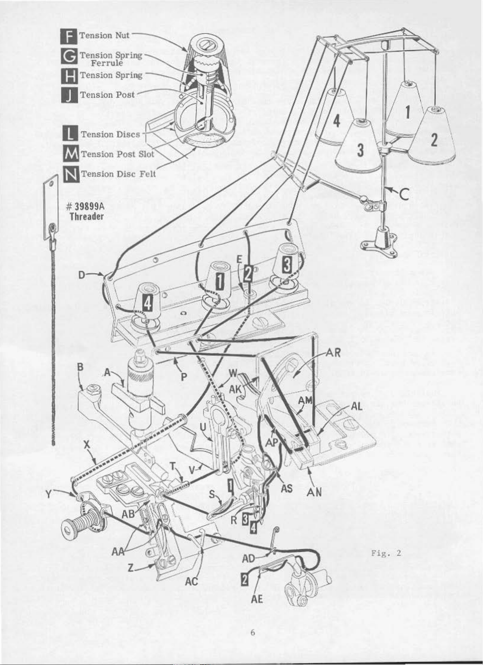
#
39S99A
Threader
6
Fig
. 2
Page 2
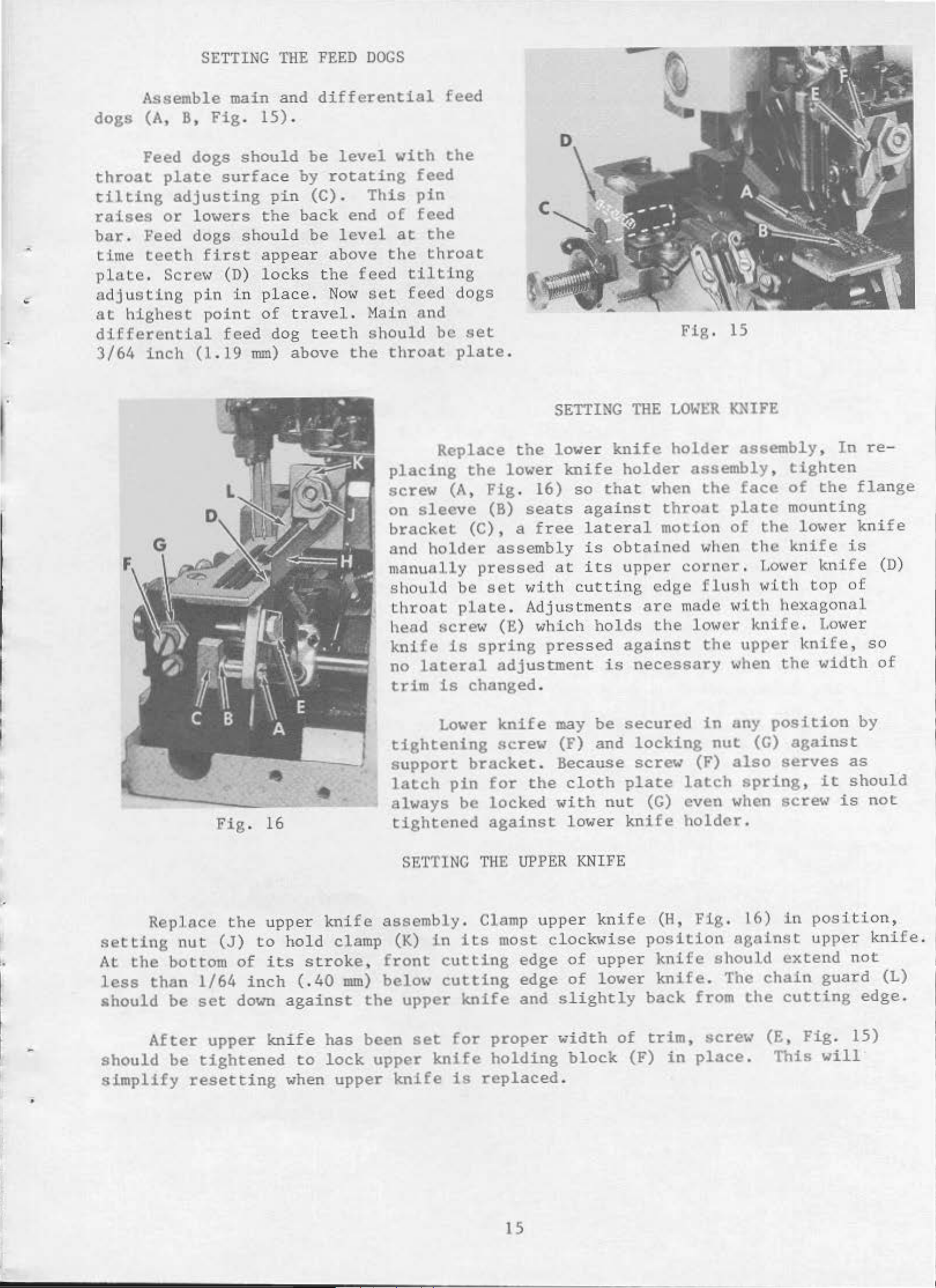
SETTING
THE
FEED
DOGS
Assemble main
dogs
(A,
8,
Feed
throat
tilting
raises
bar.
time
plate.
plate
adjusting
or
Feed dogs
teeth
Screw
adjusting
at
highest
differential
3/64
inch
Fig.
dogs
should
surface
lowers
shoul
first
(D)
pin
in
point
feed
(1.19
and
15).
pin
the
d
appear
l ocks t
plac
of
tra
dog t
mm)
above
differential
be
level
by
rotating
(C).
back
be
This
end
level
above
he
feed
e.
No
1~
set
vel.
eeth
Hain
should
the
with
feed
pin
of
feed
at
the
the
throat
tilting
feed
and
throat
feed
the
dogs
be
plate.
set
C
SETTING
THE
Fig
.
15
LOWER
KNIFE
Fig.
16
Replace
placing
screw
on
(A,
sleeve
bracket
and
holder
manually
should
throat
head
knife
no
lateral
trim
be
plate.
screw
is
is
Lower
tightening
support
latch
always
pin
be
tightened
the
the
(C),
lower
Fig
(B)
. 16)
seats
a
free
assembly
pressed
set vlit
Adjustments
(E)
which
spring
adjustment
changed.
knife
screw
bracket.
for
the
locked
against
lower
knife
so
that
against
lateral
is
at its
h cutt
holds
pressed
may
(F)
be
and
Because
cloth
1•ith
lower
knife
holder
when
throat
motion
obtained
upper
ing
edge
arc
the
against
is
necessary
secured
locking
screw
plate
nut
(G)
knife
holder
assembly,
the
plate
of
when
corner
flush
made
with
lower
the
in
nut
(F)
latch
even
holder.
assembly,
tighten
face
of
mounting
the
the
.
Lo1•er
lower
knife
with
hexagonal
knife.
upper
when
any
(G)
also
knife,
the
position
against
serves
spring,
when
sere<>'
In
the
knife
top
Lower
width
it
is
re-
flange
knife
is
(D)
of
so
of
by
as
should
not
SETTING
Replace
setting
At
the
less
should
nut
bottom
than
be
After
should
simplify
•
be
resetting
the
(J)
1/64
set
upper
upper
to
of
its
inch
down
knife
tightened
knife
hold
clamp
stroke,
( .
40
against
has
to
lock
when
upper
mm)
the
been
assembly.
(K)
front
below
in
cutting
cutting
upper
set
upper
knife
knife
THE
Clamp
its
knife
for
is
replaced
UPPER
upper
most
proper
holding
clock,.ise
edge
edge
and
KN
IFE
knife
of
upper
of
lower
slightly
width
of
block
.
(H,
position
knife
knife.
back
trim,
(F)
in
Fig.
analnst
should
The
from
screw
place.
16)
chain
the
(E,
in
position,
upper
extend
cutting
Fig.
This
not
guard
edge.
15)
will
knife.
(L)
15
Page 3
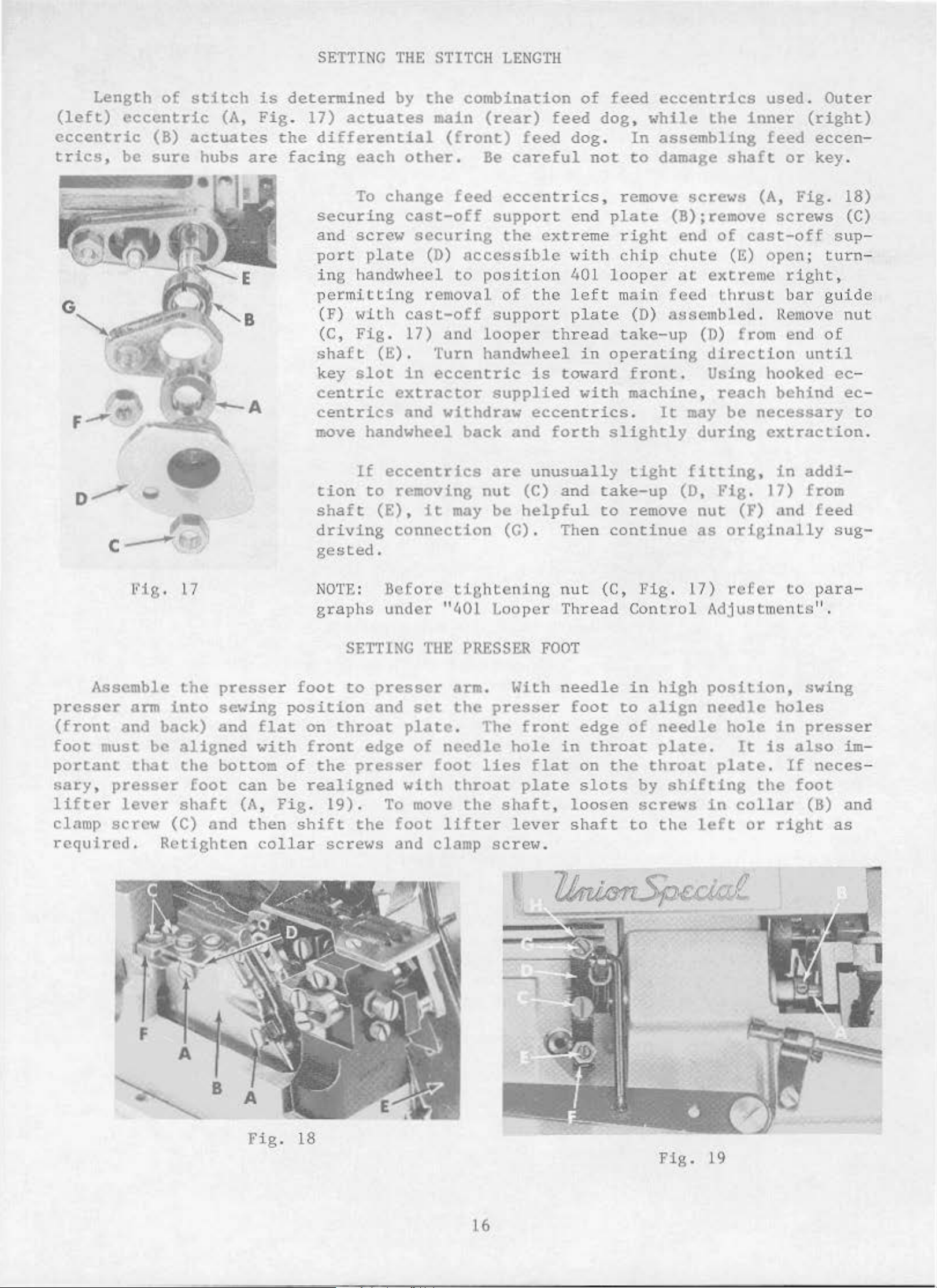
SETTING
THE
STITCH
LENGTH
Length
(left)
eccentric
eccentric
trics,
be
of
(B)
sure
stitch
(A,
actuates
hubs
are
is
determined
Fig. 17)
the
differential
facing
securing
and
port
ing
permitting
(F)
(C,
shaft
key
centric
centrics
move handwheel
by
actuates
each
To
other.
change
cast-off
screw
securing
plate
handwheel
IJith
Fig.
slot
cast-off
17)
(E).
in
extractor
and
the
(D)
removal
combination
main
(rear)
(front)
Be
feed
eccentrics
support
the
accessible
to
positio
of
supp
and
looper
feed
feed
careful
extre
n 401 l oop
the
ort
t h
dog.
end
w
left
plate
read
Turn handwheel i n
eccentric
is
tot<ard
supplied
withdraw
back
eccentrics
and
forth
of
feed
dog,
not
eccentrics
while
In
assembling
to
damage
the
shaft
, remove screwH (A,
plate
me
right
ith
chip
m
take-up
operating
with
slightly
ain
(D)
front.
machine,
.
(B); remove
end
chute
er
at
feed
a~semb!ed.
of
(E)
extreme
thrust
(D)
direction
Using hooked
reach
It
may
be
during
used.
inner
(right)
feed
or
Fig.
screws
cast-off
open;
right
bar
Remove
from end
until
behind
necessary
extraction.
Outer
eccen
key.
18)
(C)
sup
turn
,
guide
nut
of
ec
-
ec
-
-
-
-
to
D__.........
c-
Assemble
presser
(front
foot
portant
sary,
lifter
clamp
required.
and
must
presser
lever
screw
w
Fig
. 17
arm
into
back)
be
that
(C)
Retighten
the
presser
sewing
and
aligned
the
botton
foot
shaft
and
flat
with
can
(A,
then
collar
tion
shaft
driving
gested
NOTE:
graphs
SETTING
foot
to
position
on
throat
front
of
the
be
realigned
presser
Fig. 19).
shift
screws
If
eccentrics
to
removing
(E),
connection
.
Before
under
presser
and
plate.
edge
with
To
the
foot
and
it
"401
THE
set
of
needle
foot
move
lifter
clamp
may
are
nut
be
unusually
(C)
helpful
(G)
. Then
tightening
Lo
oper Thread
PRESSER
FOOT
arm. With
the
presser
The
front
hole
lies
throat
the
flat
plate
shaft
lever
screw
.
and
nut
needle
foot
edge
in
throat
on
slots
,
loosen
shaft
tight
take-up
to
remove
continue
(C,
l'ig.
Contro
in
high
to
align
of
needle
plate.
the
throat
by
screws
to
fitting,
(D,
nut
as
17)
Fig.
(F)
originally
rc
l Adjustments
position,
needle
hole
It
plate.
shifting
ln
collar
the
left
in
17) from
and
Eer co
holes
in
is
also
If
the
or
foot
right
addi-
feed
sug-
para".
swing
presser
im
-
neces
-
(6) and
as
F
A
~
B
Fig
. 18
16
Pig.
19
Page 4
SETTING
THE PRESSER
FOOT
(Continue
d)
The
su-.:e
the
locked.
Adjust
no
higher
l'hould
before
(G)
and
plate.
its
NOTE:
foot
plate
fo
highest
to
. C
ot
when
tilted
foot lifter
presser
lifter
than
be from
the
presser
locked
To
assemble
position.
Tractor
be
1/16
heck
to
presser
down
in
lever
arm
lever
upper
1/16
to
foot
with
nuL (H).
chip
presser
inch
make
foot
front.
arm
does
not
stop
looper
l/8
begins
guard, turn
foot
(l.59
sure
i.s
1~aised
401
(D,
Fig
bind
sere'~
or
spre
inch
(1.59
to
rise.
Re-assemble
to
be
set
mm)
401
fon,ard
and
to
LOOPER
THREAD
. 19) and
and
(E,
ader
rise
Fi
g .
will
to
:3.18 m
Tl1is
handwheel
with
from
the
front
the
when
19)
presser
so
permit;
m)
adjustment
chip
until
wall
fron
t
overedge needle
highest
position
CONTROL
ADJUSTMEN
collar
that
then
free
guard,
upper
wall
does
and
(B)
foot
pre
lock
motion
should
fabric
of
401
of
401
not
front
TS
secure
release
sser
foot
the
of
be
knife
needle
needle
interfere
por.t'lon
the
lever
can
nut (F).
foot
guard
lifter
made
'~ith
and
assembly
slot
slot
with
of
shaft.
is
be
raised
There
lever
screw
cloth
reaches
in
presser
in
throat
presser
foot
Be
un-
is
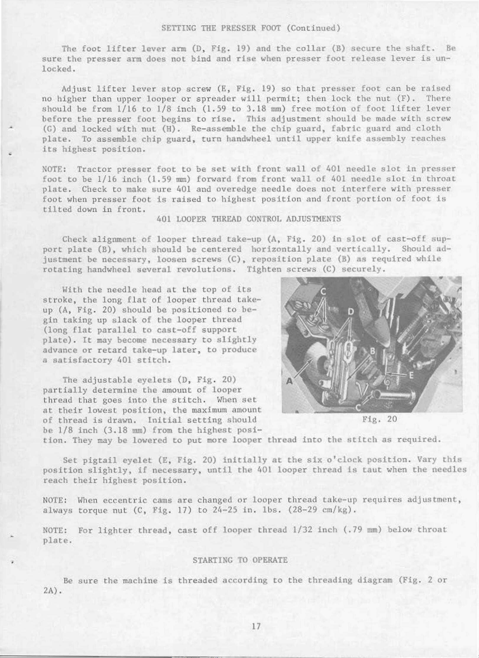
Check
port
plate
justment
rotating
l·li.th
strol<e,
up
(A,
gin
(long
plate)
Fig
taking
flat
.
advance
a
satisfactory
The
partially
thread
at
their
of
thread
that
alignment
(B),
be
necessary,
which
handwheel
the
the
.
up
long
20)
needle
should
slack
parallel
It
or
may
retard
become
401
adjustable
determine
goes
lowest
is
position,
dra-.>n.
of
several
head
flat
of
to
take-up
stitch
eyelets
the
into
Initial
looper
should
be
loosen
revolutions
at
the
of
looper
be
pos
itione
the
looper
cast-off
necessary
later,
.
(D,
amount
Lhe
stitch
the
setting
thread
centered
screws
top
thr
of
ead
d
thread
support
to
slightly
to
produce
Fig
.
20)
of
looper
.
\~hen
maximum
take-up
horizontally
(C),
.
reposition
Tighten
its
take-
to
be-
set
amou11t
should
(A,
Fig.
20)
in
and
plate
scre\.'S (C)
slot
of
vertically.
(8)
as
required
securely
fig.
cast-off
Should
.
20
sup-
ad-
while
be
1/8
tion.
position
reach
NOTE: Hhen
al
ways
NOI"E:
They
Set
their
inch
may
pigtail
slightly,
tor
que
For
lighter
(3.18
be
eyelet
highest
ecce
nt ·
nut
mm)
£-.:om the
lowe-.:ed
(E,
if
necessary,
position.
dc
(C,
cams
Fig.
thread,
to
Fig
are
17)
cast
highest
put
.
20)
chang
to
off
more
initially
until
ed
2lo-25
looper
posi-
looper
the
or
401
looper
in. lbs
thread
at
looper
.
thread
into
the
six
thread
(28-29
1/32
the
o'clock
thread
take-up
em/kg).
inch
stitch
is
(.
79
as
position
taut
when
requires
mm)
below
required.
. Vary
the
needles
adjustm<'nt,
throat
this
plate.
•
2A).
Be
sure
the
machine
is
STARTING
threaded
TO OPERATE
according
to
the
threading
diagram
(Fig.
2
or
17
Page 5
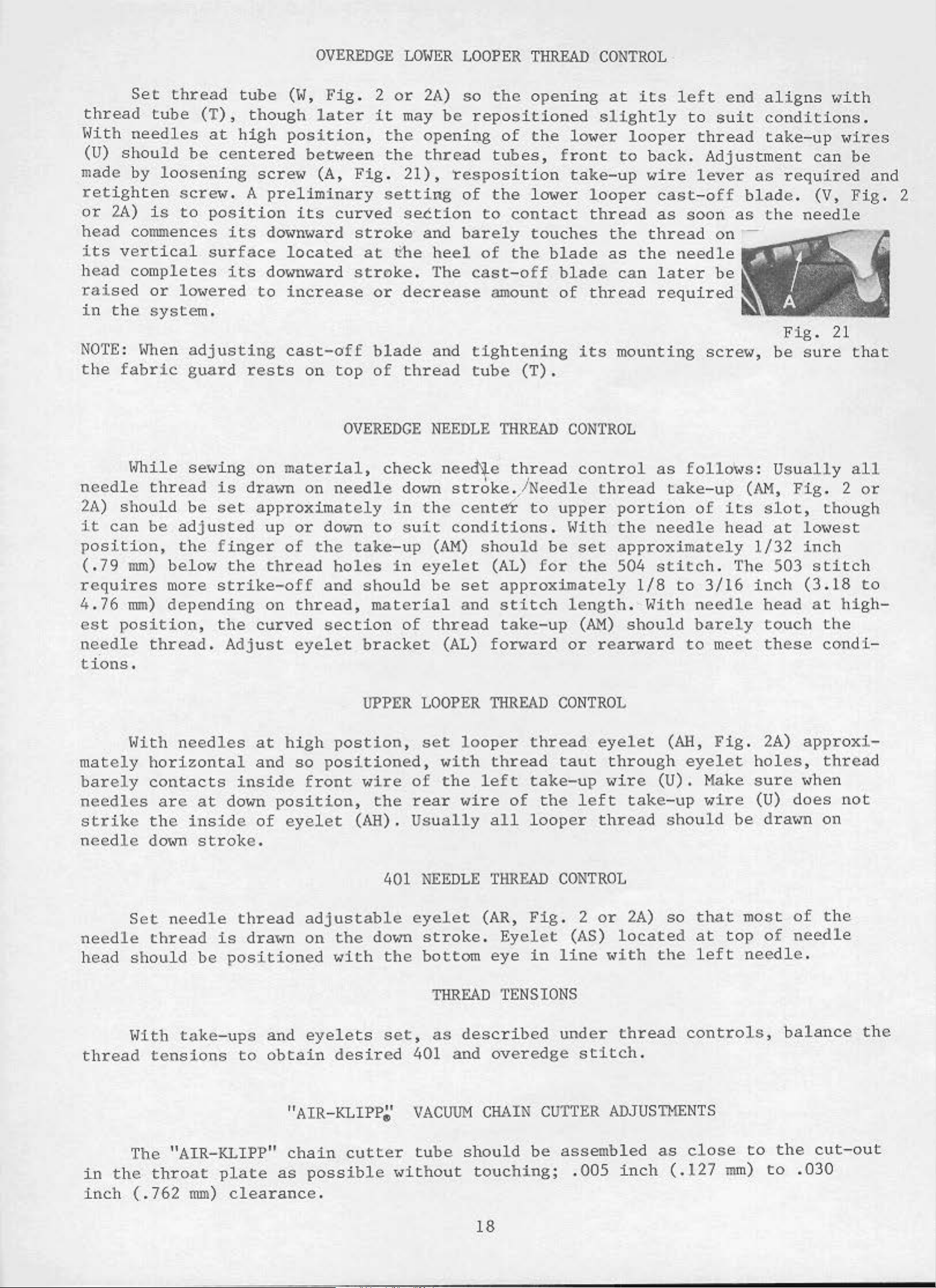
OVEREDGE
LOlmR
LOOPER
THREAD
CONTROL
·
thread
lhth
(U)
should
made
ret
ighten
or
2A)
Set
needles
by
thread
tube
(T
at
be
loosening
screw.
is
to
position
head commences
its verti
head
completes its
raised
in
the syst
NOTE
the
: l,lhen
fabric
or
cal
lm
<ered
surface
em.
adjusting
guard
tube
),
though
high
centered
screw
A
preliminary
its
downward
downward
to
rests
(14,
Fig.
late
position,
between
(A,
its
Fig.
curved section
stroke
located
stroke.
increase
cast-off
on
top
OVEREDGE NEEDLE
2
or
r
it
the
the
setting
at trhe
or
blade
of
2A)
may
so
be
openiQg
thread
21),
resposition
of
and
barely
heel
T
he
decrease
and
thread
the
opening
repositioned
of
the
tubes,
lower
front
take-up
the
to
lm~er
contact
touches
of
the
cast-off
amount
blade
blade
of
tightening
tube
(T).
THREAD
CONTROL
at
slightly
l
ooper
thread
the
as
thread
its
mounting
its
looper
to
back.
wire
cast-off
as
thread
the
can
later
required
left
to
end
suit
thread
Adjustment
lever
soon
on
as
·-
needle
be
screw,
aligns
conditions.
take-up
as
required
blade.
the
needle
Fig.
be
sure
with
can
(V,
21
wires
be
and
Fig.
that
2
l<hile
needle
2A)
it
should
can
position,
(.79
mm)
requires
4.76
est
mm)
position,
needle
tions.
Hith
mately
barely
needles
strike
needle
se~~ing
thread
be adj
the
below
more
is
be
set
usted
finger
the
strike-off
depending
the
thread.
Adjust
needles
horizontal
contacts
ar
e
at
down
the
dmm
inside
stroke.
on
material
drawn on
approxi
up
or
of
thread
on t
curved
eyelet
at
high
and
so
inside
position,
of
eyelet
,
needle
mately
down
the
take
holes
and
hread,
should
material
section
bracket
UPPER
postion,
positioned,
front
wire
(AH). Us
check need'i).e
to
down
in
suit
-up
in
stroke.
the
centet
conditions.
(AH)
eyelet
be
set
and
of
thread
(AL)
LOOPER
set
loo
with
of
th
e
the
rear
wire
ually
thread
' '
/Needle
to
upper
l'ith
should
(AL)
be
for
set
approximately
stitch
length.
take-up
fon1ard
THREAD
per
thread
thread
left
take-up
of
all
looper
or
CONTROL
taut
the
control
thread
portion
the
approximately
the
(AH)
504
should
rearward
eyelet
through
wire
left
tak
thread
as
follol<s:
take-up
of
needle
stitch
1/8
to
With
needle
barely
to
(AH,
eyelet
(U). Hake
e- up
should
(Al'l,
its
slot,
head
1/32
. The 503
3/16
inch
head
touch
meet
these
Fig. 2A)
holes,
sure
wire
(U)
be
drawn on
Usually
Fig.
all
2
though
at lowest
inch
stitch
(3.18
a t
high-
the
condi
approxi-
thread
'<hen
does
not
or
to
-
Set needle
needle
head
should
t•ith
thread
The "
in
the
inch
thread
tensions
AIR
throat
(.762
be
take
-KLIPP"
mm)
thread
is
drawn
positioned
-up
s and
to
obtain
"A IR-
chain
plate
as
clearance
401
adjustable
on
the
with
eyelets
do•10
the
set,
desired
KLIPP~'
cutter
possible
.
NE
EDLE tHREAD
eyelet
stroke.
bottom
THREAD
as
401 and
VACUUM
tube
"ithout
(AR,
Fig
Eyelet
eye
in
TENSIONS
described
overedge stitch
CHAIN CU
should
touch
be
ing;
CONTROL
. 2
line
under
TTER
or
(AS)
2A)
located
with
thread
ADJUSTIIENTS
assembled
. 005
inch
so
the
.
as
( .127 m
that
at
left
most
top
needle.
controls,
close
to
m)
of
of
needle
balance
the
to
. 030
the
the
cut-out
18
Page 6
"AIR-KLIPP&'
VACUUH
CHAIN
CUTTER
ADJUSTHENTS
(Continued)
knife
single
the
station
stroke
of
"A
etld
of
lent
Check
to
The
that
trim
"AIR-KLIPP"
strand
The
cutting
ary
.
Care
must be
IR-KLIPP"
stro
ke.
Lubricate
to
Union
knife
.
of
thread
edge
knife
taken
chain
felt
Special
pressure
chain
cutter
when
of
the
a minimum
to
provide clea
,
cutt
oil
er
wick and movable
Specification
is
turning
movable
of
tube
"hen
only
enough
should
machine
knife
l/64
inch
rance
t he movable
No
. 175 .
to
be
capable
ove
should
(.40
bet
..
knife wit
ensure
of
proper
cutting,
r by hand.
extend
rom)
een
"hen
movable
knife
h a
beyond
is
straight
at
at
cutting.
NOT
Lhe
extre
knlfe
Lhe
mineral
TEARING,
cutting
me
right
and i
extre
me
Set
end
nner
right
oil
movable
a
ed
ge
of
of
wal
l
equiva-
SKIPPING
(A)
Overedge
l.
2. R
3.
4. Recheck
(B) 401
:
If
stitch
Reche
echeck
Recheck
Skitch
skipping
ck
lo"
er
overedge
upper
upper
occurs,
lo
oper.
need
looper
looper
SPECIAL
check
to
le
guard
or
spreader
or
spreader
and/or
needle
sett
ADJUSTMENTS
set
to
to
adjust
ting
ing
.
lower
needle
the
.
looper
setting.
following:
setting
.
1.
2.
Recheck 401
Rechec
3 Check
Thread
4.
Should 401
k 4
01
401 l
Contro
loop
needl
ooper
er
e gu
ca
l Adjustm
chain
skipping
to
401
ard
st-off
ents
needle
settings
ea
rn
take-up
".
occur,
setting
.
timing
recheck
.
"Sett
-
ing
see
note under
The
Presser
"401 Looper
Foot"
.
19
Page 7
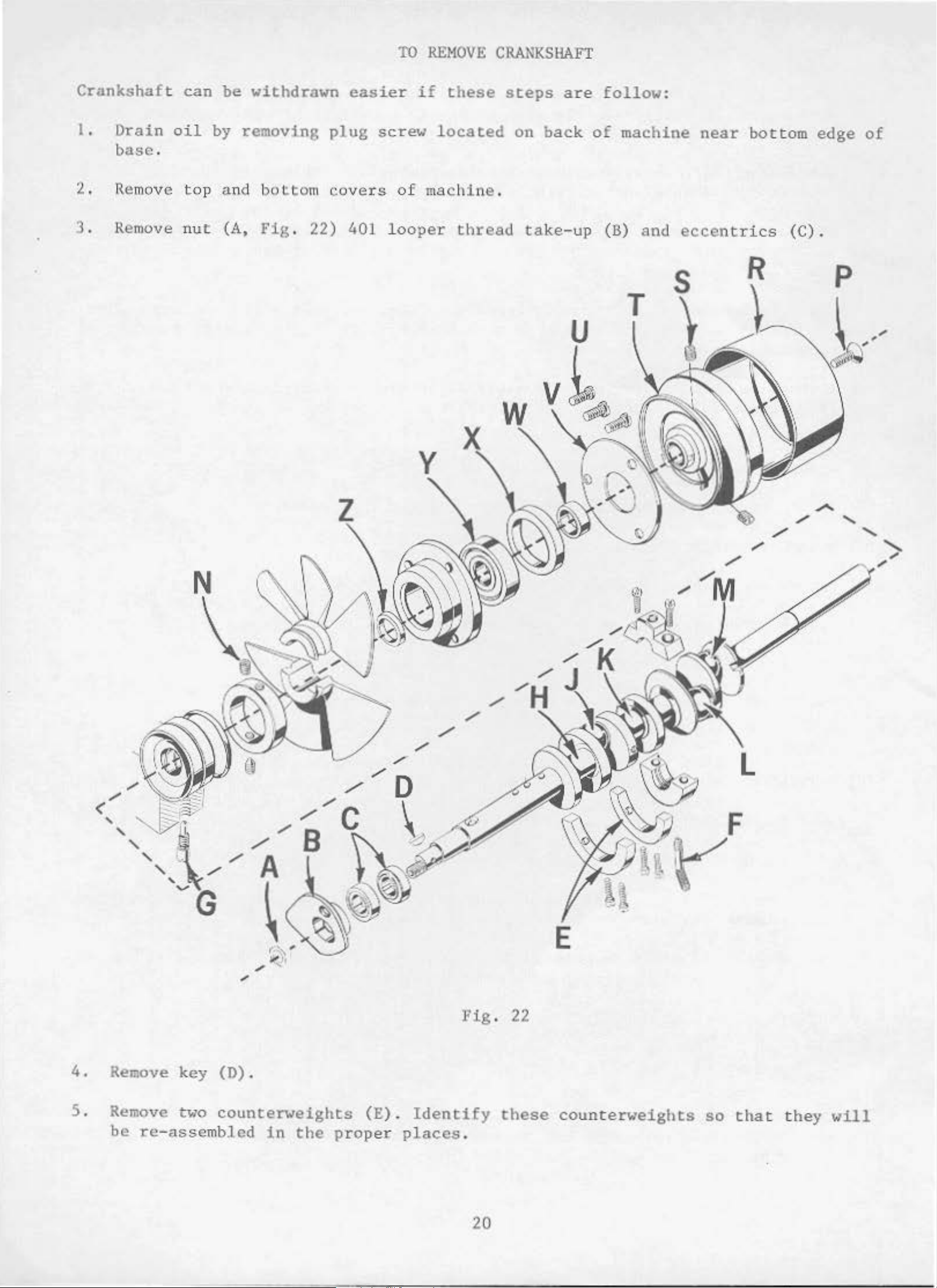
TO
REMOVE
CRA...~KSHAFT
Crankshaft
I.
2. Re
3. Remove
Drain
base
.
move top and
can
oil
nut
be
withdrawn
by
removing
(A,
bottom
Fig
.
22)
easier
plug
covers
401
if
screw
of
loo
per
these
located
machine.
thread
steps
on
take-up
are
back
follow:
of
machine
(B)
T
and
near
eccentrics
s
bot
R
tom
(C).
edge
p
of
<
'
/
'
/
'
'
'
/
Fig
/
E
. 22
4.
S. Remove two
Remove
be
re-assembled
key
(D).
counterweights
in
the
(E). Identify
prop
er
places.
20
these
counterweights
so
that
they will
Page 8
T.O
REMOV'Jl. CRANl<.Sl\Al?'.t ( Con
l:.
i.nued)
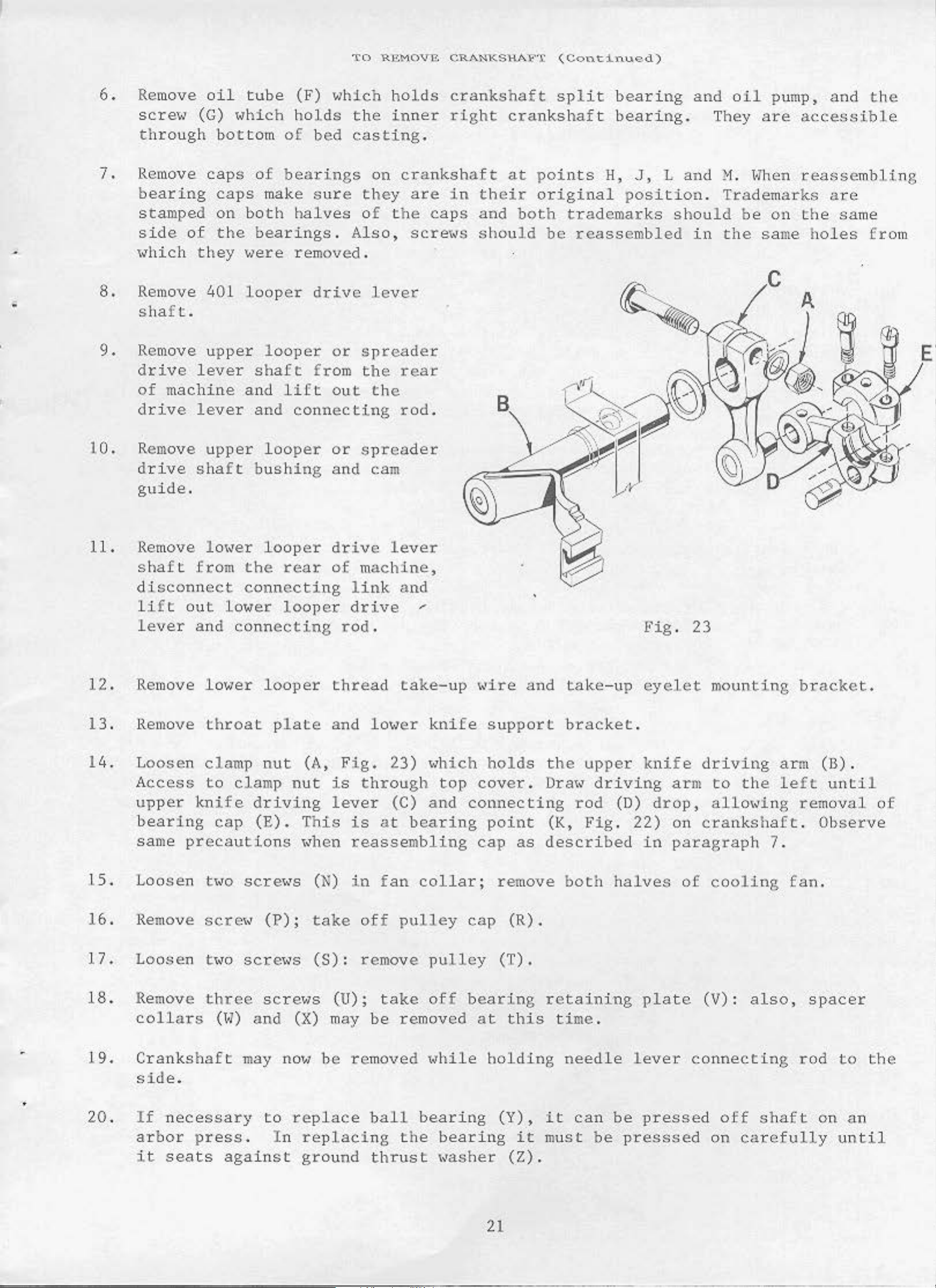
6.
7.
8.
9.
Remove
scre\·1
thro
ugh
Remove
bearing
stamped
side
of
"hich
Remove
shaft.
Remove
drive
of
machine
drive
oil
(G)
caps
they
401
tube
which
bottom
of
caps
on
the
make s
both
bearings
'1ere
looper
of
bearings
upper looper
lever
lever
sha£ t fr
and
lift
and
(F)
holds
~1hich
the
bed
casting.
on
ure they
halves
.
of
Also
removed .
drive
or
om
out
lever
spreade
the
the
connecting
holds
inner
cra
are
the
crankshaft
right
nksh
in
caps
, screx<s
·r
rear
rod
.
aft
their
and
should
split
crankshaft
at
points
original
both
trademarks
bt'
reassembled
bearing
bearing.
H,
J,
p
osition.
and
Land
should
in
oil
They a·
~1.
pump,
re
~lhen
Trademarks
be
on
the
same holes
and
the
accessible
reasse
mbling
are
the
same
fro
m
E
1
0.
11.
12.
13.
1
4.
Remove
drive
upper
shaft
guide.
Remove
shaft
l01~er
from
disconnect
li
ft
out
lever
Remove
Remove
Loosen
Access
upper
and
lower
throat
clamp
to
knife
bearing
sa
me
precautions
looper
bushing
looper
the
connecting
lower
connecting
looper
plate
nut
clamp
drivi
cap
(E).
or
and
drive
rear
of
looper
thread
and
(A,
nut
ng
is
lever
This
"hen
sp
reader
cam
lever
machine,
link
drive
and
~
rod.
take-up
l01•er
Fig.
23)
"h
through
is
(C)
at
and
bearing
reassembling
knife
ich
top
~~ire
and
support
holds
cover.
the
Dra"
connecting
point
cap
(K,
as
described
take
-up eyelet
bracket.
upper
driving
rod
(D)
Fig.
Fig
knife
drop,
2
2)
in
.
23
mounting
driving
arm
to
the
allo,,•ing
on
crankshaft
paragraph
bracket.
arm
left
removal
7 .
(B).
until
.
Observe
of
.1.5.
16.
17.
Loose
n
Remove
Loosen
18. Remove
19.
20.
coll
Cr
side.
If
arbor
it
ars
ankshaft
necessary
seats
t"o
sere«
tHo
three
(~
I)
press.
against
screHs
(
P);
scre1•s
scre'ls
and
(X) may
may no"'
to
replace
In
replaci
ground
(N)
take
(S):
(U);
be
in
fan
off
collar;
pulley
remove pulley
be
re
moved
ball
ng
thrust
take
off bearing
removed
1~hile
bearing
the
bearing
~~asher
remove
cap
(T).
at
holding
(Y),
(R).
this
it
(Z).
both
retaining
tim
e .
needle
it
can
must
be
halves
plate
lever
be
pressed
press
of
cooling
(V):
connecting
off
sed on
fan
also,
r od
shaft
carefully
.
spacer
to
on
an
until
the
21
Page 9
21
22
.
Carefully
bly
and
.
Before
kets.
prevent
observing
of
cranksha
con
stant
reassembling,
Coat
oil
the
leakage
ft.
testing
oil
TO
REMOVE
reverse
Ch
ecking
for bin
thoroughly
drain
.
No
plug
. 1 Crane Lead
CRANKSHAFT
of
the
exploded
ds
durin
with
foregoing
g
clean
a
(Con
operations
view draw
reassembly
and
sealing
Seal
dry
is
tinu
ings
the
compound
recommended.
wi
ed)
for
ll
top
loca
also
and
before
should
tion
prove
bo
ttom
reassembling
simplify
of
various
help
covers
ful
reassem-
parts
.
and
gas
to
-
tL
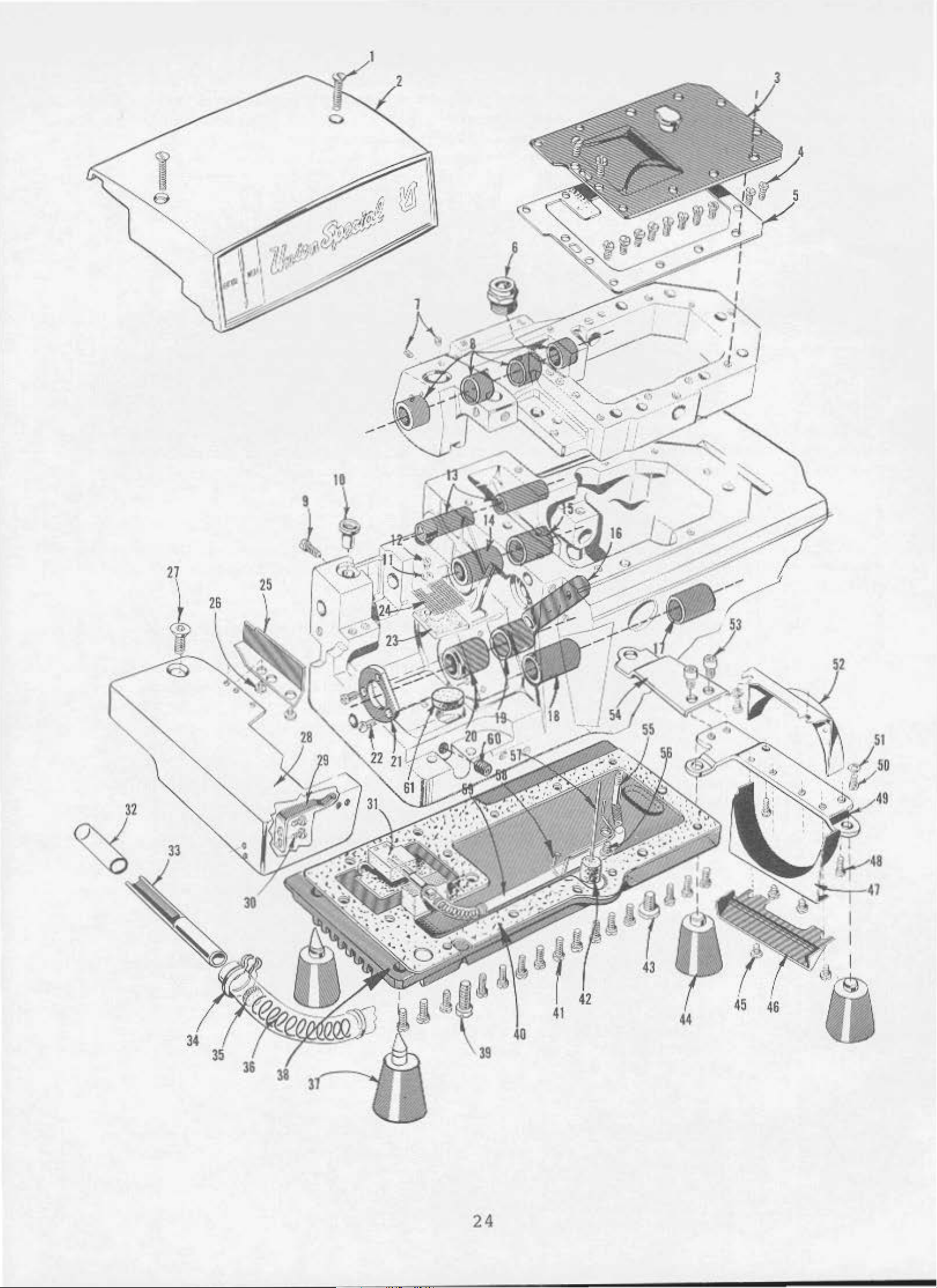
LUSTRATIONS
This catalog
of
various
actual
listing
a
req
uired
the
in
ordering
cated
bly
. E
position
in
Numbe
position
Component
by
indenting
xample:
sections
of
the
the
rs
in
of
parts
parts
has
in
parts
par
the
tha
. Always
been
of
the
ticu
first
t p
art
of
their
the
machine
with
lar
ORDER
arranged
mechanism
.
their
view
column
in
use
sub-assemblies
description
being
the
the
to
On
the
part
are reference
illustration.
pa
s
ING
are
rt
REPAIR
sim
plify
shown
page
numbers ,
shown.
number
which
under
PAR
or
dering
so
that
opposite
descr
numbers onl
Ref
erenc
lis
ted in
can
the
be
description
TS
repair
the
the
ipti
furnished
on
e numbers
the
parts.
parts
illustration
and
y,
and
second
of
the
for
the
may
merely
should
repairs
Exploded views
be
seen
will
number
indica
never
column.
main
sub-assem-
be
of
are
in
found
piec
te
be
indi-
thei
es
used
r
18
19
20
21
22
23
24
25
26
27
catalog
parts
ed
tration
29477
29477
39852 A
22587 M
39516-62 5
39516-626
39516-627
39541
In
in
77
30-106
51
C067
258
th
; no
for
the
.
MF
MB
Blk
.
- 228
Blk
.
A
E
ose
the
description
cases "'he
specific
various
Cranksha
for
Crankshaft
for all
re a
usage
machines
and,
ft
Styles
Needle
Needle Bea
Needle
Needle
Yood
Vent
Feed
Cork
Nut - - - - - - - - - - - - - - - - - - - - 1
part
will
if
and
and
Styles
Scre
Scre
Plug, birch
Plug
Drivi
Plug
are
necessa
Needle
39800
Driving
w - - - - - - - - - - - - - - - - - - - - 1
w - - - - - - - - - - - - - - - - - - - - 2
Bear
Beari
is
be
CA
Needle
ex
cept
ring,
ing,
ng,
- - - - - - - - - - - - - - - - - - - - - - - 1
ng E
common
mentioned
not
ry,
Driving
and
CB
Driving
39800
Connecting
. 0625 i
.06
26 i
. 0627
- - - - - - - - - - - - - 1
ccentric
- - - - - - - - - - - - - - - - - - - 1
to
all
in
the
same,
the
differences
Connecting Rod
- - - - - - - - - - - - - - - - 1
Connecting
CA
and
Rod
nch
nch
inch
Key
the
(1.588
(1.590
(1.593
- - - - - - - - 1
the
description
the
specific
CB
Assembly - - - - - - 1
machines
will
Rod
- - - - - - - - - 1
mm)
mm)
mm)
Assembly,
Assembly,
dia
meter
diameter
dia
met
er
covere
. However, when
usage
be
shown
d by
will
---
in
-
--
- - -
this
be
the
-28
-28
-28
mention
illus
the
-
-
At
the back
in
this
only
the
book.
part
of
the
This will
number
is
book
facilitate
known.
will
be
locating
found a
22
num
the
eri
ill
cal
ustrati
ind
ex
on
of
and
all
the
descript
part
ion
s
sho
when
'm
Page 10
IDENTIFYIN
G PARTS
•
When
too
small
tinguish
Part
IMPORTANT! ON
PART
IS
Success
SPECIAL
sub
sidiaries
approved
ciency
and
Genuine
parts
your
are
guarantee
the
for
one
numbers
ORDERE
construction
a
complete
part
from
represent
D.
in
the
Needles and
and
scien
durabil
authorized
tific
ity
needles
stamped
with
of
the highest
catalog
another
ALL
ORDERS, PLEASE
USE
operaton
Repair
principles,
are
are
assured
packaged
the
permits,
stamping
that
the
same
GENUI
of
these
Par
ts
as
di
stributors
and
.
Union
Special
quality
each
is
part
NE N
furnishe
arc
with
part
are
similar
is
stamped
identified
in
appearance.
regardless
INCLUDE PART
EED
LES
machi
AND
nes
can
d by
. They
are
NAME
REPAIR
be
the
desig11 ed
made with utmos t
labels
trademark
in
materials
marked
, U S Emblem. Each
and
of
AND
with
by
catalog
its
letter
STYLE
PARTS
secured
Union
only
Special
according
precision.
~
workmanship.
part
symbols
in
which
OF
with
Corpo
.
number.
Pa
which
they
~lACHINE
appear
FOR
genuine
ration, its
to
the
~~ximum
Genuine
most
effi
repair
trademark
rts
dis-
.
lmiCH
UNION
-
is
Prices
are
~~ise
forwar
directed.
Torque
distance
a
driver,
of
torque
All
unless
hand
as
The
are
ded
f.
A
(measured
by a
etc
.
~~ny
will
straps
otherwise
tightly
scre
ws
strictly
o.
b.
shipping point
charge
lever
of
these
tighten
and
eccentrics
noted.
as
possible,
requiring
net
cash
is made
in
inch-pounds)
(in
inches
devices
the
part
All
unless
a
specific
and
to
TORQUE
or
to
should
other
TE~lS
subject
. Parcel
cover pos
REQUIR~fENTS
is
a
rotating
feet)
are
the
nuts
.
available
correct
be
tightened
,
bolts,
otherwise
torque, will
to
change
Post
tage
shipments are
and
insurance.
forc
This
is
,
which
acco
amount and no
to
screws,
noted
.
be
indicated
with
e
(in
mplished
when
19-21
etc
out
notice.
insured
pounds)
by a
set
at
tighter
wrench, screw
the
.
inch-pounds
.,
should
on
the
All
unless
applied
proper
(22-
be
tightened
picture
ship
throug
24
men
ts
other-
h
amount
em/kg)
by
•
plat
es
.
23
Page 11
6
'
1
2
24
I
I
lb
Page 12
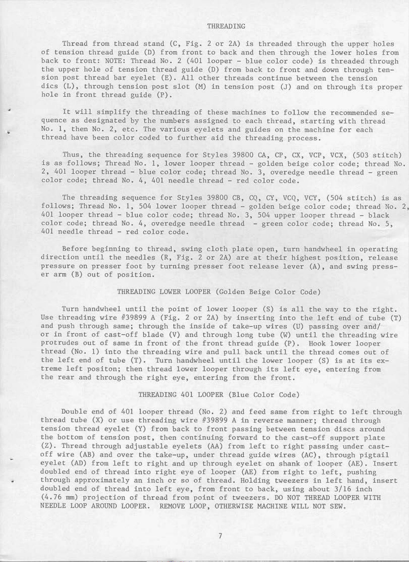
THREADING
Thread
of
tension
back to
the
sion
dies
hole
upper
post
(L),
in
It
quence
No.
1,
thread
Thus,
is
as
follm<s;
2,
401
color
code;
from
thread
front:
hole
thread
through
front
\dll
as
designated
then
have
No.
been
the
looper
thread
thread
guide
NOTE: Thread
of
tension
bar
eyelet
tension
thread
simplify
guide
the
by
2,
etc.
color
threading
Thr ead
thread
No.
-
No.
stand
(D)
from
No. 2 (401
thread
(E).
post
(P
threading
the
The
numbers
various
coded
sequence
1,
blue
4,
color
401
(C,
Fig.
front
guide
All
slot
(M)
).
of
assigned
eyelets
to
further
for
lo\<er
looper
code;
needle thr
2
to
lo
(D)
other
in
these
aid
Styles
thread
ead
or
2A)
back
oper
fro
and
-
m
threads
tension
machines
to
and
the threadi
39800
thread
No.
-
red
is
threaded
then
blue
color
back
continue
post
each
guides
CA,
-
golden
3,
color
through
code)
to
front
(J)
to
follo"
thread,
on
the
ng
process.
CP,
CX,
beige
overedge
code.
through
the
is
and
dmm
bet"een
and
on
the
starting
machine
VCP,
colo:r
needle
the
lo"er
upper
holes
threaded
through
the
throug
tension
h
its
recommended
"ith
for
VCX,
code;
thread
each
(503
thread
thread
holes
from
through
ten-
proper
se-
stitch
No.
-
green
)
The
follo"s
401
color
401
; T
looper
code;
needle
Before
direction
pressure
er
arm (B)
Tu
rn
Use
and
or
threading
push
in
front
protrudes
thread
the
(No.
left
treme left
the
rear
threading
hread
No.
thread
thread
thread
beginning
until
on
out
pre
the
sser
of
handwheel
wire
through
of
cast-off bla
out
end
1)
of
of
in
tube
positon;
and
through
sequence
1,
504 lo\<er
-
blue
No. 4,
-
red
color
to
color
ov
thread,
needles
foot
by
position.
THREADING
until
/139899
same;
same
to
the
in
A
through
front
threading
(T) . Turn
then
the
thread
right
for
eredge
code.
(R,
turning
LOWER
the
point
(Fig.
de
(V)
Styles
looper
code;
thread
needle
S\<ing
Fig
. 2
presser foot
LOOPER
of
2
or
the
of
inside
and
the
through
front
1<ire
hand,.heel
lower
eye,
looper
entering
39800
thread-
thread
cloth
or
2A)
(Golden
lower
2A)
by
of
and
pull
until
CB,
CQ,
golden
No. 3,
plate
are
release
Beige
loop
er
inserting
take
- up
long
thread
back
the
through
from
CY,
504 up
-
green
open,
at
their
(S)
wires
tube
guide
until
lower
its
the
VCQ,
beige
per
turn
lever
Color
is
into
(W)
(P).
left
front
VCY,
color
looper
color
hand>~heel
highest
Cod
all
the
(U)
until
the
looper
eye, entering
.
(504
code;
thread
code;
position,
(A),
and
e)
the
way
left
passing
the
Hook
lo,.er
thread
(S)
stitch)
thread
-
thread
in
operating
swing
to
the
end
of
over
threading
looper
comes
is
at
its
is
black
No.
release
press-
right
tube
and/
wire
out
of
ex
from
as
No.
5,
(T)
-
2,
.
THREADING
Double end
threa
tension
the
(Z)
d
tube
bottom
.
Thread
(X)
thread
of
through
off 1<ire (AB)
eye
let
doubled
•
through
doubled
(
4.
76
NEEDLE
(AD)
end
f rom
of
approximately
end
mm)
LOOP
of
projection
AROUND
of
401
or
use
eyelet
tension
and
over
left
thread
thread
LOOPER.
looper
threading
(Y)
post,
from
then
adjustable
the
to
into
an
into
of
take
right
right
inch
left
thread
REHOVE
401
thread
"ire
back
continuing
eyelets
-up,
and
up
eye
or
so
ey
e, from
fro
m
LOOP,
LOOPER
(No.
1139899
to
front
(AA)
under
through
of
looper
of
thread.
point
OTHERWISE
(Blue
2)
and
A
passing
fon>ard
from
thread
eyelet
front
of
tt<eezers.
7
Color
feed
in
reverse
between
to
left
guide
on
(AE)
fro
Holding
to
back,
~lACHI
Code)
same
fro
m
manner;
tension
the
to
cast-off
right
passin
1<ires (AC),
shank
m
right
of
to
tweezers
using
DO
NE
NOT
WILL
about
THREAD
right
thread
through
looper
left,
in
left
NOT
to
left
through
discs
around
support
g
under
pigtail
(AE).
pushing
hand,
3/16
inch
LOOPER
SEI~.
through
plate
cast
Insert
insert
IHTH
-
Page 13
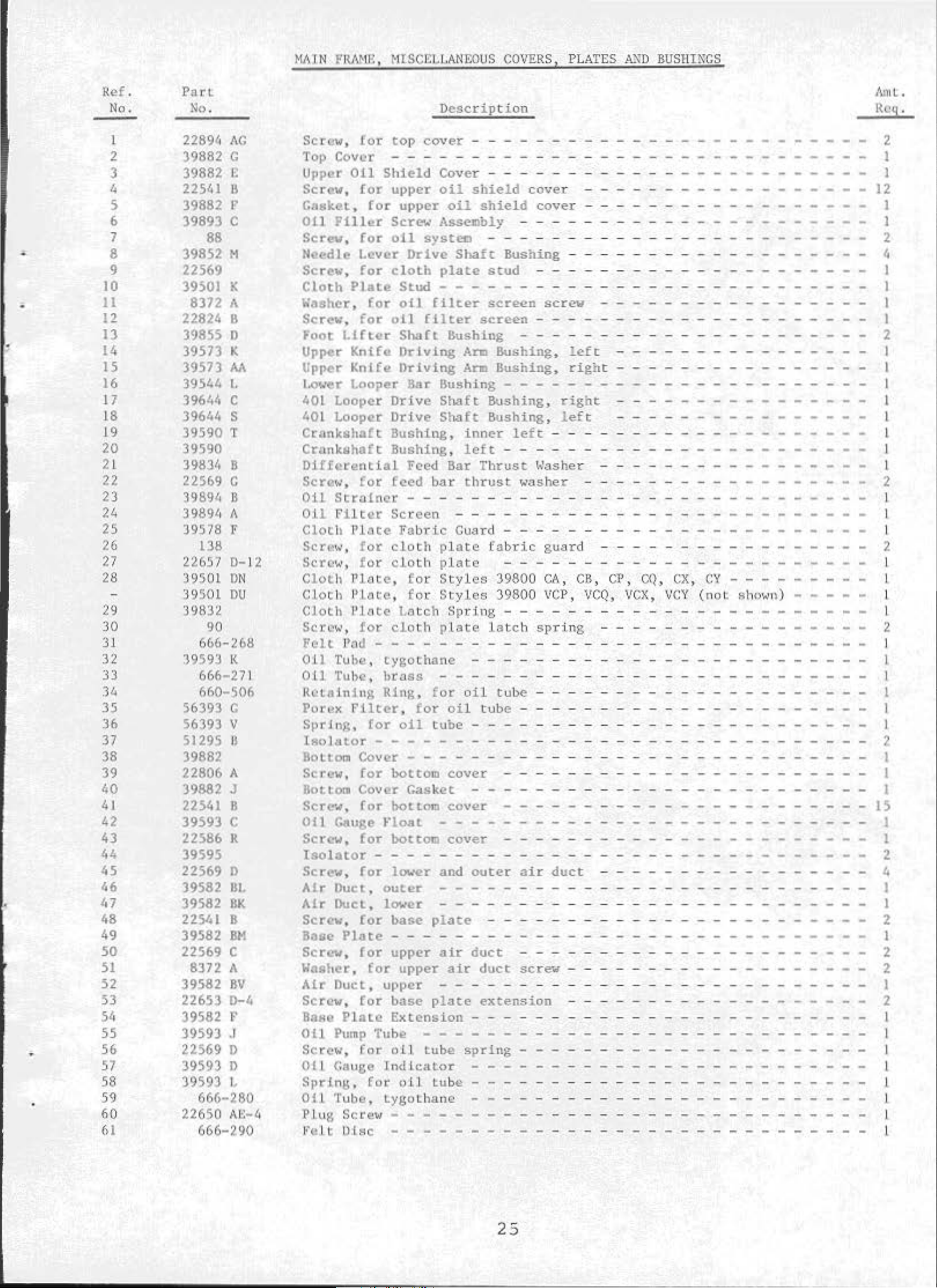
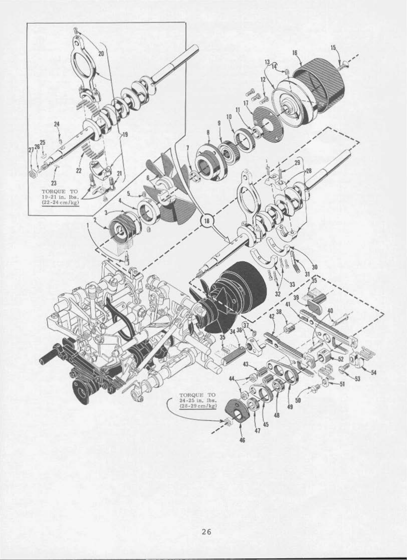
f1A1
N FIWIIJ,
~1lSCELt.ANEO
U S
COVER
S,
PLATES
A~D
BUSlllNCS
Ref .
No.
l
2
3
4
s
6
7
8
9
10
II
12
13
14
IS
16
17
18
19
20
21
22
23
24
25
26
27
28
29
30
31
32
33
34
35
36
37
38
39
40
41
~2
43
44
45
46
47
48
49
50
51
52
53
54
55
56
57
58
59
110
61
Part
No
.
22894
AG
39882 c
39882 c
22541
Jl
39882 r
39893 c
88
39852 H
22569
39501
K
8372 A
22824 8
39855 0
39573 K
39573 A.\
395'4
1,
39644 c
39644 s
39590 T
39590
3983'•
B
22569 c
39891,
39891, A
B
39578 F
138
22657
D-
12
39501 ON
39501
ou
39832
90
666-268
39593 K
666-271
660-506
56393 G
56393 v
51295 ll
39882
22806 A
39882
22541
39593
J
8
c
22586 R
39595
22569
39582
39582
225lo
39582
0
BL
BK
I B
811
22569 c
8372 A
39582
BV
22653 D-4
39582
F
39593 J
22569 D
39593 D
39593
I,
666-280
22650
""-4
666-290
Description
Screw,
Top
Upper
Screw,
Casket,
011
Screw,
Needle Lever
Scre:w,
Cloth
Washer,
Screw,
Foot
Upper
Upper
Lower
401
401
Crankshaft
Crankshaft
Differential
Scre~~o•,
011
Oil
Cloth
Sere
Scrc:::w, for
Cloth
Cloth
Cloth
Sere
Felt
OJ.l
011
Rctalnillg
Porex
SprJn~,
lBolutor
BoLtom
Screw,
BoLtoo Cover Gasket - -
Screw,
0!1
Screw,
Isolator
Screw,
Air
Alr
Screw,
Bose
Scr~~,
Washer,
Air
Screw,
BaHc
011
Scr:cw,
OLI
Sprlng,
OU
Plug
Jo'
c I t 0
for
top
cover
- - - - - - - - - - - - - - - - - - - - - - - 2
Cover - - - - - - - - - - - - - - - - I
Oil
Shield
!or
upper
for
upper
Filler
Plate
Llfter
Kntfe
KnHe
l.ooper
Looper
for
for
for
for
Sere.•
oil
cloth
Stud
oll
oil
Shaft
Driving
Driving
Drive
Looper Drive
Bushing,
Bushing,
for:
feed
Strainer
filter
l'lote
....
•,
Plate,
l
'lote,
Plate
....
•,
Pod - - - - - - - - - - - - - - - - - - - - - - - - - - - - -
Tube,
Tube:,
filter,
Screen
Fabric
for
cloth plate
clot
La
for
cloth plate
cygothanc
brass
Ring,
for
oil
- - - - - - - - - - - - - - - - - - - - - - - - - - - - -
Cover - - - - - -
for
bottom
for
botLom
Cover - - - - - - - - - - - - - - - - I
oil
shield
oil
shield
Assembly
system
Drive
plate
- - - - - - - - - - - - - - - - - - - - - I
filter
filter
- - - - - - - - - - - - - - - - - - - - 2
Shaft
stud
screen
scr~cn
cover
cover
- - - - - - - - - - - - - - - - - - - - - - I
- - - - - - - - - - - -
- - - - - - - - - - J
---
Bushing - - - - - - - - - - - - - - - 4
- - - - - - - - - - - - - - - - - - - I
screw
- - - - - - - - - - - - - - - - -
- - - - - - - - - - - - -
Bushing - - - - - - - - - - - - - - - - - - - -
Arm
Bar
Feed
b.ar
Am
Bushing
Shaft
Shaft
B.ar
Bushing,
Bushing,
inner
left
Thrust
thrust
Bushing,
Bushing,
- - - - - - - - - - - - - - - - - - - - - - -
left
- - - - - - - - - - - - - - - - -
-...•asher
left
right
right
left
- - - - - - - - - - - - - -
t,'asher - - - - - - - - - - - - - - - - -
- - - - - - - - - - - -
- - - - - - - - - - - -
- - - - - - - - - - - - - - - -
- - - - - - - - - - - -
- - - - - - - - -
- - - - - - - -
Guard
h
plate
fo
r
Styles
fo
r
Styles
tch
Spr
- - - - - - - - - - - - - - - - - - - - - - - - - - -
for
oil
for
oi
l tube - - - - - - - - - - - - - - - - - -
tube
cover
cover
- - - - -
fabric
- - - - - - - - - - - - - - -
39800 CA,
39800 VCP,
ing
- - - - - - - - - - - - - - - - - - - - -
latch
- - - - - - - - - - - - - - - - - - - - -
tube
- - - - - - - - - - - - - - - - - - - - - - -
- - - - - -
gu.ard - - - - - - - - - -
CJ\
, Cl' ,
VCQ,
spring
- - - - - - - - - - - - - - - - - - - - -
CQ, CX,
\fCX, V
- - - - - - - - - - - - - - -
CY
CY
(not
-------
shown} - - - - -
- - - -
Gauge FloaL - - - - - - - - - - - - - -
for
bottom
- - - - - - - - - - - - - - - - - - -
for
lower and
l)uct,
DueL, lower - -
Plote
Duct,
Plate
Pump
C8uge
Tube,
Screw-
outer
for
base
- - - - - - - - - - - - - - - - - - - - - - - - - - - - - -
for
upper
for
upper
upper
(or
base
Extension
Tube - - - - - - - - - - - - - - - - - - - - - - - - - - - -
for
oll
Indicator
Cor oil. tube - - - - - - - - - - -
Lygolhili
- - - - - - - - - - - - - - - - - - - -
1sc
- - - - - - - - - - - - - - - - - - - - - - - - - -
cover
---
plate
air
air
-----
plate
tube
)C
- - - - - - - - - -
outer
--
duct
duct
extension
air
duct
----------------
-
--
- - - - - - - - - - - - - - - - - -
- - - - - - - - - - - - - - - - - -
- - - - - - - - - - - - - - - - - - - - - -
screw
- - - - - - - - - - - - - - - - - - -
------------
- - - - - - - - - - - - - - - - -
- - - - - - - - - - - - - - -
------
-
- - - - - - - - - - - - - - - - - - - - - - -
spring
- - - - - - - - - - - - - - - - - - - - - - -
- - - - - - - - - - - - - - - - - - - - - - -
- - - - - - - - - - - - - - - - - - - -
--
- - - - - - - - - -
--
- - - - - - -
--
---
Amt.
Roq.
- 12
I
I
2
I
I
I
I
1
l
I
l
2
I
l
I
2
I
L
l
I
2
I
I
I
I
I
I
2
I
I
I
1$
I
I
2
4
I
I
2
I
2
2
I
2
I
I
l
I
I
l
l
I
25
Page 14
TORQUE
19
· 21
(22-2<cm/kg)
in.
'1'0
1
bs.
L--"
"'
/
/
"'
/
/
"'
/
/
'I'OJIQJ.;P.
2•-2s l
(28-29c:mlkg)
n.
'1'0
lbs
26
.
Page 15

Ref.
No
CRANKSHAFT
Par
t
No
.
.
AND
FEED HECHAN!
Description
SN
Aro
t .
Rcq.
1
2
3
4
5
6
7
8
9
1.
0
11
12
13
14
15
16
17
18
39690 A
39890 c
660-443
39
591
11
2289/o
D
39591 L
39590 .J
39590 G
660-268
39590
R
39590 s
22569 B
395
21
c
95
22769
ll
39821
39590 H
29477
~IF
29477 HB
19
20
21
22
23
24
25
26
27
28
29
30
31
32
33
34
35
36
37
38
39
40
41
42
43
44
45
46
47
39852
22587
A
77
}{
39516-625
39
516-626
39516-
39541
C067
627
30-106
51-
228
A
E
258
39890 E
97
A
39691
39593
227io7 8
39591
J
K
39835 B
22
894 J
39835 c
22894 u
39535
3
983
J
5 A
39536 B
3953/o C
39534
39536
c
39536 e
39536
AF
39868 R
39540
B-10
Blk.
Blk.
39540 ll- 8
48
49
•
50
39540 8-
39540
39536
93
ll-8
AE
A
10
51
52
53
5(•
39838
93
Stu
d, f
or
crankshaft
Crankshaf t
11
"0
Ring, for
Crank Chamber
Spot Sere"'
Crank.
Thrust
C
ranksha
Crankshaf
Ball
S
pace
Screw,
Pulley
Ser
Pulley Cap - - - - - - - - - - - - - - - - - - - - - - - - - - - - l
Crankshaf
Cranksh
Chamber
Bearing
r
Sere~,
e•
...
•,
39800
Crankshaft
Styles
Need
Needle
Need
Needle Be
Hood
Ven
Feed Dri
Cork
~ut
Split
Bearing
ScL"'et..'
Bearing,
cran k
Cooling Fan
',
for
crank
Cooling
H
ash~r
f t
t Jla
Collar
for
- - - - - - - - - - - - - - - - - - - - - - 1
for
t
aft
CA and
except
le
Screw - - - - - - - - Scre
le
Plug
t Plug - - - - - - - - - - - - - - - - - - - - - -
Pl ug - - - - - - - - - - - - - - - - - - - - - - - -
- - - - - - - - - - - - - - - - - - - - - - -
,
- - - - - - - - - - - - - - - - - - - - - - - - - - - - 1
llall Bearing
ll Bearing
Stop
- - - - - - - - - - - - - - - - - - - - - - - - - - 1
bal.l bea
f
or pulley
pulley
Ba
ll
Bea
and
Needle
CB
and Needl e
39800
Or'lvi
w - - - - - - - - - - - - - - - - - - - 2
Bearing
l\ e
aring,
aring
,
birch
vit
)g
and
for spl i t
Cr.ankshaft Counter
Oil
Pump
Screw, f
Crankshaft
ed Adj
Fe
Screw,
Feed
Feed
Feed
Feed Bar
Differenti
Hain
Feed
Nu
t ,
~lain J.o~eed
401
Looper
Naio
Hain
all
Differential
all
if
ferential Peed
D
a
ll
Differential Fee
Scret..•,
Ha
i n
Pee
d Lift B
Sere•
...
Differential
Tub
e - - - - - - - - - - - - - - - - - - - - - - - -
or cran
usti
for
Leveling
Screv
llor
Bar Gui
Fee
llar
for
Feed D
Fee
Styles - - - - - - - - - - - - - - - - - - -
Style
Styles
Peed Dog (Sec
•,
,,
Guide Block
Driv
~l
d Bar - - - - - - - - - - - - - - - - - - - - - -
[)ri vi ng St ud B
fee
Bar
d Driving
s - - - - - - - - - - - - - - - - - - - - - - -
for
for dif fer
kshaft
Counterweight
ng Pi n - - - - - - - - - - - - - - - - - - - - - -
fee
d adjust
Le
ver
for
fee
de,
ri ght - - - - - - - - - - - - - - - - - - - -
ing Stud - - - - - - - - - - - - - - - - - - - - - -
Feed Bar - - - - - - - - - - - - - - - - - -
d bar d
Drivi
Thr
ead Take-up - - - - - - - - - - - - - - - - - -
riving
feed
- - - - - - - - - - - - - - - - - - - - - - -
d Sa
main
loc
feed
k - - - - - - - - - - - - - - - - - - - - -
Feed
bea
ring
inner
shaft bear
chamber
Fan
Housing
Collar
ring
cap
ring Rctai
r~tainin
nriving
- - - - - - - - - - - - - - - - - - - 1
ri gh t - - - - - - - - - - - - - - - - - - - 1
ing,
Collar
inner
- - - - - - - - - - - - - - - - - 1
cooling
right
fan
- - - - - - - - - - - - 1
collar
- - - - - - - 2
- - - - - - - - - - - - - - - - - - - - - - 1
- - - - - - - - - - - - - - - - - - - 1
- - - - - - - - - - - - - - - 1
- - - - - - - - - - - - - - - - - - - - - I
g
pl ate and
- - - - - - - - - - - - - - - - - - - - 2
- - - - - - - - - - - - - - - - - - - - 1
ni•>t Plat
COt)l)eCting
e - - - - - - - 1
housing
Rod
Assembly) f
- - - - - - - - - 3
or Styl
es
- - - - - - - - - - - - - - - - l
Driving
CA
and
ng
Connect
, . 0625
. 06
26
,
.0
627
Eccentric
Oil
Pump - - - - - - - - - - - - - - - - - - - -
bearing
weight,
counterw
,
ing
- - - - - - - - - - - - - - - - - - - - -
d l
eveling
- - - - - - - - - - - - - - - - - - - - -
ushing
riving
ng
Connection
Ecc
entr
ic, for
Ecc
entr
i c , f
Dr
i vi ng Eccent
Driving
r.
l)ri
ving
dog - - - - - - - - - - - - - - - - - - - - -
Pages
ctltial feed
l)
og (See
43
CB
ing
inch
inch
inch
Connect
Rod
(I.
(
(1. 593
i ng
- - -
As~ero
588
I.
590 mm)
Rod
bly
mm)
mm)
Ass
d
iameter
di
ameter
di
ameter
emb
l y, for a
ll
- - - - - - - - -
- - - - -
- - - - - - -
- - - - - - - - - - - - - - - - - - - - 1
Key - - - - - - - - - - - - - - -
and
oil
pump - - - - - - - - - - - -
right
left
pin &l)d fee
stud - - - - - - - - - -
Eccentric,
and
Pages
- - - - - - - - - - - - -
eight
- - - - - - - - - - - - - -
lever
- - - - - - - - - - - - - - - -
or
ric, for
CO
I)n
- - - - - - - - - - - - -
d bar
- - - - - - - - - - - - - - -
- - - - - - - - - - - - - - - - -
No
. 5 1/8
No
. 8
for No
ection.
gui
de,
ri
ght - - - - - - -
gauge,
3/16
or
No
. 5 1
. 8 3/16
- - - - - - - - - - - - - - -
al.l
Styles
12 3/1 6
/8 gauge,
or
gauge,
12 3/16
gauge,
45) - - - - - - - - - - -
dog
43
and
45)
- - -
28
28
28
l
1
1
I
1
I
l
1
2
1
l
4
1
1
2
I
I
1
1
2
I
I
2
2
1
I
I
l
I
1
I
1
I
I
1
1
27
Page 16

10
30
3
36
1
28
Page 17

NEEDLE
DR
IVE
HECHANISM
AND
TAKE-UP
S
Ref.
No.
1
2
3
4
5
6
7
8
9
10
11
12
13
14
15
16
17
18
19
20
21
22
23
24
25
26
27
28
29
30
31
32
33
34
35
36
Part
No
.
39852 J
22733
CL21
2289l, c
228%
39852
1~0-3
L
c
660- 220
660- 416
39852
22852
lo0
c
- 139
39863 c
39852 E
39573
A
660-442
39852
D
22852 c
40
- 139
51236 A
H0
- 3
39843 D
22652 B-
10
22588 A
39863 D
39863 J
39863
22752 B
22564 D
39852 F- 5
39852
39852
F-8
F-
12
22784 L
39852 N
28
c
39852 K- 5
39852
K-8
39852 K-12
22738 B
605
120
GS
D
escription
N
eedle
Pipe
Se t Sere•,, - - - - - - - - - - - - - - - - - Spot
Needle
"0"
Retaining
Needle
LO\•.'er
Need
Thrust
Ret
aining
dl
Nee
Link
dle
Nee
Sere",
503
4
01
Lo,;er
Sere"''
Needle
Styles
Nee
dle
Styles
Nee
dle
Styles
Needle,
gauge
Guide
Sere",
Clean
Sere"
Lever
Wool
Ring, for
Lever
Sere''',
\~asher,
Looper
le
Lever
W
asher
e
Driv
Sere,<,
Hasher,
Pin,
Wool
Lever D
Scre\·7, for
for
Needle
Needle Thread
Looper
Screw, for
£or
Head,
Head,
Head,
ScreH, for
Needle Head Eyelet,
ScreH, for
Needle
Needle
Nee
dle
Ser
e,,•
Scre~J,
for
on
Bar
for
er
(oi
- - - - - - - - - - - - - - - - - - - Roller
Yarn
Ring
- - - - - - - - - - - - - - - 1
for needle
for
Thread
Drive
Ri
ng,
e
Lever
for
f.
for
Yarn
needl
Thread
Threa
take-up
ma
marke
marke
Head
Head
Head
for
fo
all
Sty
les
- - - - - -
needle
l
"ick)
Pi
- - - - - - - - - - - - -
needle
, f
or
needle
needle
Take
Sha
- - - - - - - - - - - - - - - - - - 2
for
needle
or
needle
- - - - - - - - - - - - - - - -
rive
t h
e
take-up
r ked
top
needles
needle
- - - - - - - - - - - - - - - - 1
needle
Sha
rust
thread
Cam
Cam
d
Take
lever
"AV
d "BN" ,
d
"AH
needle
Eyelet,
Eyelet,
Eyelet,
39852
r No.
5
39852
1/8
39800
gui
de
bar
- - - - - - - - - - - - -
n - - - - - - - - - - - - - - -
guide bar
lever
lever
lever
- up
ft
- - - - - - - - - - - - - 1
drive
drive
drive
ft
Thrust
cla
cam pul
Pull-off
Pull-off
- up
lever
·
h~ire
" ,
" , f
top
fo
for No
for No.
F-5
or
- - - - - - - - - 1
Wire
lever
lever
l ev
mp
col
Lever
for No
for
or
head
r No. 39852 F- 5
39852
F-12
, 8
CA
3/16
and
- - - - - - -
as
- - - - - - - - - - 1
roller
- - - - - - - - - - 1
- - - - - - - 2
drive
- - - - - - - - 1
lever
er
- - - - - - - - - 1
Clamp
la
r - - - - - - - - - 1
l -
off
- - - - - - - - 1
- - - - - - - - - - 1
- - - - 4
. 5
No
. 8
No.
eyelet
. 39852
1/S
3/
12
- - -
- - - - - - -
39852
F-
8 - - - - - - - -
pi n - - - - - 2
shaft
Collar
- - - - - - 1
- - - - - - - - - 1
- - - - - - - 1
gauge,
16
gauge,
3/16
- - - - - - - -
F-8
F-12
- - - - - 1
- - - 1
as
- 1
all
all
gauge,
- - - -
all
- - -
- - - - - - - - - -
gauge
CB
machi
- - - - - - · - - - - -
nes;
12
3/16
required
r e
Amt
Req.
1
1
1
1
1
1
quire
1
1
1
1
1
2
1
1
1
1
1
2
.
d
120
37
•
38
39594 N
87
GAS
u
Need
le
39800
Oil
Sere"',
Spl
,
for
CA
asher
for
all
and
oil
12
CB
- - - - - splasher
29
3/16
- - - - - - - - - - - - - - - - -
gauge
machines
except
Styles
2
1
l
Page 18

'J
01\QUJ.;
1
9-2
1
{22-24
ln.
<"
m
'J'O
Jb
s.
/)tg)
16
30
Page 19

LOWER LOOPER
DRIVING
HECHANISM
Ref.
No
.
1
2
3
4
5
•
6
7
8
9
10
11
12
13
14
15
16
17
18
19
20
21
22
23
Part
No.
39808 D
39151
52344
77
660-206
22
894
AE
482 c
22894 c
39894 c
12982
22894
J
538
39644 X
39644 R-2
39644 R- 5
666-
255
39644 F
22729 0
22729 E
77
39844
39
844 B
39544 D
39544 B
Description
Lower
Nut,
Looper,
for
lower
marked
looper
"ACZ"
bar
- - - - - - - - - - 1
- - - - - - - - - - 1
Lower Looper Bar - - - - - - - - - - - - - - - - - - - 1
Screw,
"
O"
S
cre
Lower Looper
Oil
N
ut,
Screw,
Screw,
Ball
Shim,
thick
Shim,
thick
Felt
Lower Looper
Screw,
Low
er
Lo
~<
er
Low
er
Lower
for
Ring,
w,
for
Sere•~,
Pu
mp
for
for
for
Joint
for
connecting
for
lowe-r
lowe-r
Shaft
f.
or
col
Oiler
oil
oil
- - - - - - - - - - - - - - - - - - - - - - 1
)>Ump
pump
ball
Guide
ball
joint
link
looper
looper
Collar
pin
bar
bar dr
drivin
iving
- - - - - - - - 1
g
lever
lever
shaft
- - - - - - - - - - - - - - 1
l ar - - - - - - - - - - - - - - 2
oiler
oiler
joint
Fork
screw - - - - - - - - - - 1
- - - - - - - - - - - - 1
gui
de
fo
rk
- - - - - - - - - 2
- - - - - - - - - - - - 1
guide
fork
, . 002
inch
- - - - - - - - - - - - - - - - - - - - - -
for
ball
joint
guide
fork,
. 005
inch
- - - - - - - - - - - - - - - - - - - - - -
Plug,
Screw,
Screw,
for
Loo
Looper
Looper
T
,ooper
for
lower
Drive
fo-r
for
co
co
connecting
per
Bar
Bar.
Ba-r
Bar Connecting Link - - - - - - - - - - - - - 1
looper drive
Lever
nnectin
nnecting
Drivit~
D-riving
Connec
g
rod
rod
link
pin
Lever - - - - - - - - - - 1
Lever
Connecting
lever
ting
Rod
connecting
- - - - - - - 1
- - - - - - - - - - - - - - 2
- - - - - - - - - - 2
- - - - - - - - - - 1
Shaf t - - - - - - - - - 1
Link
Pin
- - - - - - - - - 2
shaft
( .
051
( .
127
- - - - 1
- - - 2
mm)
as
required
mm)
as
required
rod 1
Amt.
Req
.
•
31
Page 20

8
<
/
.....
17
18
4\
'I
-®·
/
/
--
'
'
'
'
'
T
ORQ
19·Z
(22
(4)
UE
1 i
n. lb$.
-2~
em/kg)
SCI'f!WS
TO
32
Page 21

UP
PER KNIFE
liND
<\01
LOOPER DRIV
ING
~!ECHANIS M
Ref.
~o.
I
2
3
4
Part
No
.
9937
39871
39870
22738
5 39572
6 39571 c
7
8
9
10
I 1
I 2
13
14
15
16
I 7
39873 B
39873
39573 A
39573 E
55235
6042 A
55235
39673
22587
22565
39644
39644 v
18
19
20
21
22
23
2l
25
26
27
28
29
30
o
22729
39644
98
482 c
22894 c
39644
395lo3 P
3951 o3 M
22562 A
396<\1
22729 £
22729 D
3961.4
39641, R-5
31
32
33
34
35
36
37
39644 X
538
66o-206
2289/o
3961.4
39644 A
3984/o A
38 22652
39
40
41
42
43
44
2289to
39808
22503
39543 E
39644
39644 L
45 39571
46
47
48
49
39536
22781
41336
39844
50 39844 D
*51 22775
*52 39644
A
0
E
E
c
K
tl
p
, u
R- 2
AF.
N
A-
AF
f
l'
B
E
c
c
M
6
Am
Nut,
Upper
Upper
Screw,
Upper
Upper
Upp
Up
Up
Upper
for
upper
Knife
Knife
for
Knife
Knife
er
Kn
ife
per
Kn
He
per Knife
Kn
ife
L
ocking
Clamp - - - - - - - - - - - - - - - - - - - - - - I
- - - - - - - - - - - - - - - - - - - - - - - - - I
upper
Holder
Clamp
Driving
Drlvl.ng Arm - - - - - - - - - - - - - - - - - - - 1
DrJ.vlng
Dr l
Washer,
Nut,
Upper
Knife
Screw,
Set
Screw,
Bushing
Bushing
Screw,
Thrust
Sere'-',
Looper
Screw,
Lo
oper
Lo
oper Bar
Cla
mp Col
Scrc
Loop
er Drive
Sere"'',
Scre
Shlm,
thick
Shim,
thick
Ball
for
for
Joint
Screw,
"0"
Ring,
Screw,
Looper
Looper
Looper H
Screw,
Scre
Looper , marked
Scr
ew. f
Cam Follower
Looper n
for
Driving
for
for
and
C!lll
and
Cam
for
Collar
for
Drive
Drive
Lever
for
Lever - - - - - - - - - - - - - - - - - l
Th
lar
to.
•,
for
Lever A
for
to.•
,
ror
ball
- - - - - - - - - - - - - - - - - - - - - - -
ball
- - - - - - - - - - - - - - - - - - - - -
Guide Fork - - - - - - - - - - - - - - - - - - - - 1
for
ball
for
for
Drive
Bar
looper
Lever
(401
older,
for
w,
for
or
cam
LockJng Cl
ar
SleevP - - - - - - - - - - - - - - - - - - - - 1
Cam Follo••er
Upper
}~ut
Screw,
looper
Looper Avoid
Looper Avoid
Screw,
Knife
,
for
looper
for
Avoid Link
for
Chain Guard - - - - - - - - - - - - - - - - - 1
looper
Link
Eccenlric
looper
Description
knife
knlfe
vJ
ng T.ever - - - - - - - - - - - - - - - - - - 1
Stu
d,
for
drivi
driving
connecting
bushing
Guide,
Guide,
bushing
clamp
Block
Stud
Al'll
Arm
for
Lever
stud
clamp
- - - - - - - - - - - - - - - I
stud
- - - - - - - - - - - - 1
- - - - - - - - - - - - - - - - - - 1
- - - - - - - - - - - - - - - - - - - - - 1
•
Thr
u~t
Hash
er
- - - - - - - - - - - - 1
Thr
us t
~las he
driv
ng
leve
i ng lever - - - - - - - - - - 1
lever
- - - - - - - - - - - - - 1
r - - - - - - - - - - - - - I
Connecti ng
rod
and can
for
for
and
Styles
all
cano
- - - - - - - - - - - - - 2
guide
Styles
guide
r
- - - - - - 1
Rod
- - - - - - 1
39800
except
- - - - - - - - - - - - 1
- - - - - - - - - - 1
CA
and
Cll
- - - - - - 1
39800
CA
and
CB
- - - - - - - - - - - - - - - - - - - - - - 1
rust
thrust
collar
\lasher
collar
Shaft
- - - - - - - - - - - - - - - - 2
Collar
- - - - - - - - - - - - - - - 2
- - - - - - - - - - - - - - - I
- - - - - - - - - - - - - - - - - - 2
- - - - - - - - - - - - - - - - - - - - - - - - 1
clump
connecting rod - - - - - - - - - - - 2
connecting
joinl
joint
joint
looper
drive
stitch)
for
looper
looper
"CY
",
follower
col
uxiliar
fluide
guide
guide
drive
Shaft
401
stitch
holde
for
amp
l ar - - - - - - - - - - - - 1
y
rod
fork, .0
fork
lever
lever
Connec
fork
shaft
t i ng Rod - - - - - - - I
- - - - - - - - - - - - - - - 2
02
, .005
inch
inch
(.051
(.127
mm)
mm)
as
required
as
required
- - - - - - - - - - - - 2
shaft-
- - - - - - - - - - - 2
- - - - - - - - - - - - - - - 2
- - - - - - - - - - - - - - - - - - 1
- - - - - - - - - - - - - - - - 1
lo
oper -
--- ---
-
----
r - - - - - - - - - - - - - - - - 1
- - - - - - - - - - - - - - - - - - - - - 1
401 s t i tch - - - - - - - - - - - - - 1
lock'tng clamp - - - - - - - - - - 1
- - - - - - - - - - - - - 1
- - - - - - - - - - - - - - - - - - - - - - - - 1
avoid
avoid
Pin
eccentric
link
pin
stud
- - - - - - - - - - 1
- - - - - - - - - - - - - - 1
- - - - - - - - - - - - - - - - 1
- - - - - - - - - - - - - - - - - - - - - - 1
Stud
avoid
- - - - - - - - - - - - - 1
link-
- - - - - - - - - - - - - - 1
Req
1
Looper Avoid Link - - - - - - - - - - - - - - - - - - - - - - 1
t.
.
I
* Used on
earlier
model mach
ine
s,
i n
place
of
Ref.
33
Nos
. 46 , 49 and
50.
Page 22

TOttQUR
14
ln.
l
be
(16cm/kgl
TO
23
\-~~
\
27
25
TORQt;E
19-21
(22
(4
-24
}
lft
cm/k
screws
TO
. lb$
g)
.
34
58
so
Page 23

(I
Tension
Nut--.._
AH
r.iiil Tension
1.'!'.1
IIJT
Ferrule
ens
~rinu-
ion
Spring---
0 Tension Post
~----.!.
P::,
\,
I
'•
NOTE:
Upper Loop
th
Ta
ru
ONL\'
ke ·Up
'l'
hruad
Wire
*3
er
should go
the
LEFT
(U)
for
0
•
8
Fig
#3
9899A
Threader
l
.
2/1
Page 24

UPPER
LOOPER
OR
SPREADER
PLATES
AliD
DRIVE,
LOI<ER
KEKM.E
Kl<IPI!
GUARDS,
PARTS
THROAT
Ref.
No.
l
lA
2
2A
••
3
)A
lo
5
(o
7
8
• 9
•to
ll
12
l)
14
15
16
17
18
19
20
21
22
23
24
25
26
27
28
29
30
31
32
33
34
35
36
37
38
39
40
41
42
43
44
45
lo6
47
loS
/o9
so
51
52
53
54
55
56
51
58
59
60
•
••
Replece.ent
•
Upper Looper
P;trt
r\
o.
39808 A
39808 c
39860
39543
22564 c
39>13 H
22768 B
39543
22565
102
395
39543 s
398&3 A
22503 F
39>13 &
22
5 L
43 T
It
KH
R
666-255
97
395
44
J
W0
- 3
1
2982
22894 J
482 c
22894 c
660-
206
22894 c
39843 c
22894
395.3
22562 A
39543 p
39843 E
L
M
39843 B
39>13
39843
22729
39
87
59/o
II
D
u
N
2252.
39
650
6
39550 E
39625
D
39825 c
39825 8
22585 A
90
39825
39880
39880
39580 F
ll
22653 6
39
543 "
88f
22892 8
14077
39550 c
22729 B
39650
39849
39550 M
39550
22
39883
41071
7.
588 J
c
-12
vith
or
Upper Looper,
39800
Upper
39800
Upper
Upper Looper
Upper Looper
Uppel:' t.oopcr
~ere"'•
Lock
Cam
Follover
l'ppe"t
Upper Looper
Screw.
ea. Followor
Felt
Plug, for
Sere\.•,
Guide
W
ool
Yarn,
Nut - - - - - -
Sc
r~·
Upper
Screw,
11
"0
Ring,
Set
Screw.
Upper Looper
Spot Screw,
Clamp
Sero
T
hrust
T
hrust
39800
Upper L
Upper
Cpper Looper
Screw,
Screw,
011
Splasher
Sere\<'
Thro<lt
tower
Kntfe Holde
N~edle
Needle Guard,
~eedte
ScrC'-·,
Screv
Needle C
Th
roat
Shi
m, for
Wo.sher,
Scre
w,
Needle Guard
Scre\o', for
Lockjng Screw,
~t.
Lower
Screw.
Lower Knife
Lowe
Lo"•er
T.o~er
Sere~,
Screw,
Nut,
Ulellbly
Spreader
for
r Kni
locking
Holder No. 39843 H iS
Description
morkod "OA
CR.
CQ,
Loopct
CS
~
m
, cQ, CY,
Spreader,
or
Screv,
for
or
Screw,
for
or
Scre1<>·, for
,
fo r bu
Sere,.., f
ah
or
CY,
VCQ,
atkQd
VCQ
aarked
Spreader
upper
Spreader
upper
SpreDder Holder Coll
UPI>Cl'
L
ll8
<m
bu
shing
",
and
"ADA",
at~d
"W'.
Holder,
looper
Holde~
looper
loo
per
d
ca
m
and
for
100/0'•0 needle
VCY;
VCY;
for
Cot
1).1.1
110/0t./
all
anuses
Stylea
.arked
or
spreader
- - - - - - - - - - - - - - - - -
or
spreader
o.r- - - - - - - - - - - - - -
or
spri!odcr
guide
cam
- - - - - - - - - - -
8\Jidc
size
gaus,es - - - -
•
needle
39800
"J"
size
...
- - - - - - - - - - - - - - - ......
CA,
- - - - - - - - - - - - - - -
- - - - - - - - - - - - -
holder colhr
sere,..
- - - - - - -
- - - - - - - - - - - - - - - - - - - - - - - - - -
1.o(lpCt
for gu1dc fork
Fork - - - - - - - - - -
or
Spreader
or
Spreader
for
co.
upp~r
Orivc
Drive
foll~~r
1~cking
Clacp
looper
Sbatt
Shaft
lockins
Buthtng, and
... ...
claap
- - - - - - - - - - - -
or
spreader
drive
- - - - - - - - - - -
... ...
- - - - - - - - - - - - - -
- - - - - - - - - - - -
level:'
... -...
for hcod
- - - - - - - - - - - - - - - ...... -
Looptt
Coll~r-
W<lshcr,
~
.rasher,
CA
ooper
Looper
for
w,
and
or
Spreader Dri\•e Lever
for
col
lor
- - - - - -
for
for
or
for
upper
up~r
looper
loo?er
Spreader
UJ)per
looper
or
or
Drive
or
spre3Cier
spreader
J.ev.-r
- - - - - - - - - - ...... - -
for
CB
or
or
or
for
oil
tor
fot' upper
splusher
clamp
Spreader
Spreader
Spreader
connecting
col)~~
- - • - - - - - - - - - - - - -
uppe.r looper
loo
per
- - • • - - - - - - - - - - - - - • - - - • - - - Drive
Drive
Drive
Le~cr
Lever - - - - - - - - - - - - - - - - - - - -
Lever
rod - - - - - - - - - - -
- - .. - - - - - - - - - -
Sh:\(t
--
Shaft
spre•dcr
or epr
or
efld(1
epr('ndcr
Thrust
Connecting Rod - - - - - - -
- -
drive
drive
drive
...
c d
Colla
--
lever
lever
- - - - -
lc
- - - - - - - - - - - -
rive shsf
drive
W3sher
- - - - - - - - - - - - - - - - - - -
, for,
Knife
throat
Pliltc, (See
Clamp Serow Nut - - - - -
plate
Pttj:)(t$
- - - - - - - .. - - - - - - - 43 and
1•5)
r SprinS - - - - - - - - - -
Guard,
Gu~rd,
for
,
for
oor
Plate
for
f
or
front,
rc.r,
rtar,
>03
or
40J
ttitch
d,
front,
and Lo"•
throat t>l(I
Rupp<lrt
(o
for
for
S04
for
er
LC suppor t
brocket
support brnckc
r
l!O
l s
titch
401
$t1teh
503
or
stitch
needle
front needle
503
or
S04
needle
needle
stitch
- - - - - -
- - - - - -
needle
8U3rd - - - - - - - - - -
504
gu•rd
At1Lch n
- - - - - - ee
dle
Knife Support 8rDckct- - - - - - - - - - -
barekct
screw-
--
- - - - - - - - - -
t - - - - -
l.ock1ng Clac.p - - - - - - - - - - - - -
needle
loeklne
Knt(e
for
lover
fe
Kn1
,£c
K
nife
for
low
for
atabl1Lztng
Hold•r
lloldcr
- - - - - - - - - - - - - - - - - - ChmJ) Spri
Cl
auard
for
~rev
Locating
kn1fe
lockins
lower
knife
-
--Stud
holder locattns
- - - - - - - - - - - - - - - - - - - - - - - - - - - ng -
amp - - - - - - er
knlfc
clamp - - - - - - - - - - 401
st
itch
cl~p
bolder
- - - - - - - - - - - - - - - - - -
- - - - -
- - - - - - - - - - - - - - - atud
...
- - - - - ......
...
- - - - - - - fronL needle guard - - - - -
- - - - - - - - - - - - - - - - - - - -
Mo
. 29126
EK
i1t
reeo:aeoded,
used
on
lr:t.tcud
later
of
.adel
the
cachines
and
~;;
mallcr
...
- - - - - - - -
and
tarser,
CP,
ex,
VCP
- - - - -
... -...
.....
...
CaG
Guide - - - - - - - - - - -
... ...
connecting
....
- - .. - - - -
-
... -...
...
- - - - -
r - - - - - -
- - - - -
...
shaft
shalt
~:er
sh.,Ct,
...
...
- .. - - - - - -
shaft
t,
ror
for
..
.....
- - - - - - - -
- - - - - -
--
- - •
- - - - - - - - - -
individual
•
,
for Styles
for
Styles
and vex;
-
all
- - ...... -
- - ...... - -
-
...
- -
...
- -
- - - -
rod-
-
-
...
- - - -
Styles
oll
Sty
39800
le$
except
-
-
- - - - - - - - -
----
...
- - - - - -
parts
.
gaua••
... ...
... ...
CA
ond
....
- ..
.....
..
- - -
... -.......
Amt.
Req
...
-
I
l
2
l
M l:'cquired
l
l
- - - - 2
2
. - . . I
I
I
J
...
- -
CB
I
2
2
I
I
l
4
1
J
I
I
l
l
l
I
I
2
I
I
I
as
requir
2
2
l
l
l
I
l
-
.....
l
l
J
I
l
l
I
I
-
.
l
l
l
I
I
I
I
l
l
l
I
I
l
l
I
ed
35
Page 25

7
41
\~
~
36
Page 26

'Ref.
No
'l'HilEAI)
Part
.
No.
't£ltSJOl{$,
RYEl.ETS ANO
PRF.SSE.R
SPRIKG
PARTS
Aln
Rcq
C.
.
I
2
3
4
5
6
7
6
9
10
II
12
13
14
IS
16
17
18
19
20
21
22
23
24
25
26
27
26
29
30
31
32
33
34
35
36
37
36
39
40
it
I
45
46
'•7
loS
lt9
50
51
52
53
Sit
55
56
57
58
59
22569
53634
8
c
39868 D
39568 1
39566 E
39868
376
X
A
39868 y
376
,,
39557 6
39857 1
39857 N
39857
398
51257
39857
39856
57
c
p
II
e
6
95
39857 J
398
57
~
CL2
1
39857 A
22569 D
5363"
39866
29477
22743
c
~
t-IA
39568 J
39568 p
22548
39892
39592
39892
6
AH
A-S
66o-469
39892 c
39592
3<.15<.12
39592
39592
39592
39.)92 Ak-4
39592
39592
39592 y
39
39592
39592
22541 D
8372
592
AN
A
AL
AF
AD
~'IR
- 2
AR-5
AR
7.
AA
AC
22569 c
8l72 A
22
704
39863 K
39663 L
22S6S
22585 R
39868 H
39868
2259
39863
22SM J
39863
z
1
H$24 C
~
fl
Sere~
i-.
Upper
Upper
Aux1lhry
L.o-
Sere-•,
F~bric
Scr~~-:,
Presset
Presser
Presser Spring
Presser
heS:)¢X
LOck
'k'<:~Shet
Ptessor
Sere"'•
Presser
Sp~ cer
P~pe
Presser
Sere·•,
Was
ihre
Ul)per
.
1
Usher,
~ll
gauges
~ll
s~vse~
..
·er
all
gauges
Nut,
Clc.oner
her,
~d
Sere\.',
Thread Tub
for
eyelet
fo.,.
:t~ov
nt:l
Loope-r
Looper
Th'C¢
Tako-up
- - - - - - - - - - - - - -
Upper
Looper
- - - - - - - - - - - - - - - - - -
Loov<:-r:
C"'s t-
for upper
- -
..
Gua
rd
- - - - - - - - - - - - - - - - - - - -
fol:
fllbric.
St)Y1t'S
Sprin&
Pl
Pl
.Plunger
S
pring
S
pring, light, for
- - - - - - - - - - - - - - - - - - - - - - - - -
Po
for
,
for
plunger
or. nel
oil
heavy
eMe
sysce
Spring Plu
- - - - - - - - - - - - - - - - - - - (oil
S
pr
in&
P
lun&N
for
thre_..d
for
thread
Tube, for
1.-oopeY'
'rhre.:td
for
l.h
(' 'l'e
Thread Tube
Sere·
... , for
'fhr
c;,
ld G
Nut,
ten~:io
Re
Te
Te
for
n
t;):ln:log
nsion
nsion
\\Usher, for
Th
read
TetH;iO
'I'h
Ten
YMd
sion
vex
t\
- - - - -
Tension
vex
-
Tension
VCY
- - - - -
Tension
VC'i
- - - - -
Tension
Tension
Upper L
VCY
L(X..•¢r
Ov
401
- - - -
l.
credgc
Stitc-h
Screw,
Sc.r<;w,
~>'
asher,
Screw,
"01
Sl.itc
Overedse
Scr¢
\..•,
Scc<n.•
- - - - - - - - - - - - - - - - - - - - - - - - -
Pigtail
Thread
Sere\..•,
Se-r:<:"~o.•,
Adju.st<lble Need
Screw. for
Necdl<:
thread
llide
.
fro
thread
Pos
t
t }1ounting
Ring, for
Post
P
ost
'3""
S"'r
t:hc<:"d
Tensi
Tensi
oop
ooper
on
Post
Disc
SJ)l"tl'&·
Spl"ing,
Spring,
Spring,
Spr:.t.oe, f
Spring
Fe
on
er
1'ensiou
lt
Disc.
for
for
for 504 s
fo
Ferru
...
.. - - - - - - - - - - -
Tension
N<:ed
le
'f
Need
le.
for 401
Co
r
ioc
for 401
h Need
Needle
f'or
J(yclc
stitch
overedge needle
Nos. 225
::;
tit
le.
Thread
upper
t . f<)r
'l'ube, for 503
for
oil
stysteo
for
adjustable
le
need
le t h
Thre3d
Frame
and
fabric-
ns
bracket
~d
RyeJet
E
yelet,
Thread
of
f
~
l.ade - - - - - - - - - -
loope-r:
~uard
mts
er
Cap Nut - - - - - -
uns,¢r
:,OJ
l.oek Nvt
Adj
, f
adjusting
t..e
ver
n•
- - - - - - - - - - - - - - - -
nger
Stud
"'t
ek)
'
ii<:~H
tvbe
tub¢
looper
iv!.>e A$!'lemb
r:e.<'ld
tt.1b<:
nston $1)t'1.
guard
!':ere~"'
.:tnd F.:1brtc Gw
Ol'l
t{l:ke-\IJ)
Styles
Eyele
eyelet
moun
ting bracket
- - - - -
- - - - - - - - - - - - nd
!-!o~u
t ,
3
9800 C6,
--
on
Styles
on St
l t:l.tt~
- 39800 C6,
:•
les
Rr,.!cket - - - - -
OQ
, CS,
39800
-
VCQ
Cl.\.
...
..
;)nd ':CY;
CQ,
<.'Y,
VCQ
CQ, CY, VCQ
- -
and
ond \'C:t;
- - - - - - - - -
- - - - - - - - - - - - - -
us
tinS
Sen
or
all
Styles
Styles
•..:
except
39800
CA
39800
and
CA
and
CB
CB
- - - - - - - - - - - - - - - -
- - - -
sere•,.; - - - - - - - - - - - - - -
- - - - - - - -
- - - - - - - - - - - - - - - - -
- - - - - - - - - - - - - - - - - - - - - -
J
- - - - - - - - - - - - - - - - - - - - - -
scrc
w - - - - - - - - - - -
thread
tC.tl$'i(H
- - - - - - - - - - - - - - - - - - - - -
ly - - - - - - - - - - - - - - - - -
'
~
Wr'i.ns
- - - - - - - - - - - -
ng - - - - - - - - - - - - - - - - - - - - - - - -
\'(..'Y;
........
- - - - - - - - - - - - - - - - - - - - - - - guide
t't - - - - - - - - - - - - - - - - - - - - - - - - -
ension
Eye
and
moun
ting
J>OS
t - - - - - - - - - - - - - - - - - - - - - - -
Bracltc
tension
let
t - - - - - - - - - - - - - - - - - post
- - - - - - - - - - - - - - - - - - -
bar
bracket
eyelet
- - - - - - - - - - - - - -
- -
... -...
- - -
..
- - - - - - - - - - - - - - - - - - - - - - - -
tension post
- - - - - - - - - - - - - -
- - - - - - - - - - - - - - - - - - - - -
-
--.
503
stitch
503
stit
titch
SOl,
t.Ol
stitch
s
titc
r
<)r
le - - - - - - -
~~UCt
:luc, hOlden beige
(!ll$:lo
n
l~vt,
Tensj<u'
ncodle
4l
l'>
~ n d
ch
u
ccdJ.e
'l
'hr eod Ptt11-off
Pull-off
looper thread tube
GOl $t1 teh
or
S04
...
needle thread
'fhre~d
Eyele
read
E.~·elet
frame
ch
h
bh lC\c,
needle
looper
tH~~lle
loo?er on
need
fo-r:
on
on
oo
le
Sl.yJ.es
Styles
Styles
Sl.yl<:.s
Styles
39800
39800 CA, CP,
39800
39800 C8.
39800
en,
CA,
CB,
CQ,
CP,
CQ,
CQ,
CY
'
CX,
CX,
C'll',
Ci
,
VCQ
- - - - - - - - - - - - - - - - - - - - -
sr.een
Nut,
chrc.<'ld
thread
22596
thr¢;:ld J)t.Jtt-
st:
i
- -
.. -...
- - - - - - - - - - - - - - - - - - - -
red
J>
ull-off cyc.lct
pull-off eyelet
- - - - - - - - - - - - - - - - - -
- - - - - - -
- - - -
... -...
- -
c - - - - - - - - - -
off
ey
Ry
Ey
elet
looper
tch
loopc.r
¢tec
- - - - - - - -
assembly
thread
t hre:l
elet
- - - - - - - - - - -
- - - - - - - - - - - - - - - - -
- - - - - - - - - - - -
d - - - - - - - - - - - -
- - - - -
- - - - - - - - - - - eyelet
- -
..... -..
- - -
t - - - - - - - - -
eye
let
- -
...
- - - -
...
- - - - - - - - - - - - -
..
- - -
...
-
\:cp
VCP
VCQ
VCQ
;)lld
and
a nd
;:.nd
and
...
--
- - - -
- -
...
..
1
I
I
1
1
1
I
I
I
I
I
I
1
1
I
I
I
I
1
I
I
I
I
1
1
I
I
I
2
1
3
OY
G
I
I
1
1
3 or 4
3
or
&
3
or
4
6
or
8
I
1
1
2
1
3
ot
4
I
I
1
I
I
I
2
I
I
I
I
1
I
I
I
2
1
2
1
37
Page 27

38
'
'
'
Page 28

401
LOOPER
T&~SION
PARTS,
MISCELLANEOUS
PLATES
AND
GUARDS
'
Ref.
No
.
1 51292 c
2 51292
3 51292
4
5 51292 A
6 51292 D
7 22571 E Magnetic
8 22569
9 39893
10 660-243
11 39878 E
12
13 43443
14
15
16 39878 c
17
18 22569
19 22585
20 39868 B
21
22
23
24 39880 F
25 93 A
26 39843
27
28 376
29
30
31
32
33
34
35
36
37
38
39
40
Part
No.
401
F-2
G Thread
109 Thread
K Screw,
39878 F Chip Guard
Q
660-210
39158 u
39878
22585
39868 M
39835 0
22541 B Screw,
21695
39843
12934 A
21695
21695
22541
8372
52958
39868
G
D
c
F
A Screw,
25
s
AB
G
AA
AM
B
A I,Jasher,
73
A Screw, I
D
J
A
77
Tension
Ferrule
Tension
Oil
Oil
Chip
Screw,
Screw,
Cast-off
Screw.
Support
Main
Throat
Screw,
Plate
Screw,
Finger
Washer -
Nut,
Finger
Screw,
Looper Thread
Cast-off
Screw,
Stitc
Sight
Gauge Seal
Guard
Nut,
Retaining
Spring
lUnge
Chlp
Feed
"Air-Klip
"Air-Klipp"
"Air-Klipp"
for
Felt
Description
h Loop
Spring,
Tension
Tension
- -
Thread
Oil
for oil
for
for
Support
for
Plate
Plate
for
- -
Drain
Gau
ge
Assembly
for
- - -
Pin
Gua
rd
chip
cast-off
support
llar Gu
p" - -
Support,
-
rear
- - - -
I<
ashe
for
for
for finger
Protector
Protector
for
for
r ,
ma
fing
- -
finger
Pad
cast
for
or
cas
l
ooper
Wire
cast-off
in
- -
Take-up
er
Tension
for
Post
Disc
401
- -
- - -
Eyelet
Plug-
sig
ht gauge
- - -
Ring
Base
hinge
Ring - -
-
- -
Cover
guard
Plate
End
ide,
- - -
- -
throat
- -
- -
- -
pin
- -
-
support
plate
Cover -
left
rear,
- - - - -
-
-
for
main
feed
er
Plate
bar
protect
protecto
- - - - -
protector
-
-
- - - -
-off
t-off
-
suppor t
thread
- -
wire
suppo
Eyelet
-
Nu
t- -
looper
- - - - -
- - -
- -
- -
-
-
-
- - - -
- - -
- - -
- - - -
- - - - -
- -
- - -
- - - -
- - -
plate
-
end
-
,
for
- - -
for
plate
- -
feed
- -
-
- -
- - -
bar
gu
ide
or
r
plate
- - -
- - -
screw
- - - -
- - -
pl
rt
ta
ke-
-
- - - - - -
-
-
-
-
- - - -
- - - - - -
-
- - - - - -
- -
- - - - - -
- - - - - -
-
- -
-
- - - -
- - -
- - - - -
-
-
- -
-
- -
-
-
- -
- -
- - -
cover
- - - -
-
- - -
-
-
- -
-
- - - -
-
- - - -
-
- -
- - -
machines w
- - -
machines
- - -
-
-- - - -
support,
- - -
guide
-
- -
- -
plate
- -
ate
up
- -
- -
-
- -
-
-
- - -
-
-
- - -
screw
eyelet
- -
-
- - - -
- - - -
-
Amt.
Req.
- - -
- - -
-
- - -
- - - -
- - -
- - - -
- -
-
- -
- -
- -
- -
- -
- - - -
- -
-
-
- - -
- 1
- 1
- 1
- 2
- 1
- 1
- - 1
- -
-
- -
- -
- -
- - - -
-
- - - -
--
- -
-
- - - -
for
- - - - 1
screw
- - - -
- - - -
- - - -
- - - -
-
-
-- - -
- -
-
- -
-
- -
- -
- -
- -
- -
- -
-
-- - -
- - -
- - -- -
- -
-
- - - - - -
-
/o
- - -
-
'~I
o
- - -
-
machines w/o
-
- -
- - -
- - -
-
- - - -
- -
-
-
-
- -
- -
-
- -
- - - -
-
-
- -
- -
-
- - - - -
-
-
- -
- - - - -
- - - -
- - - -
- - -
- -
-
- - - - -
-
-
-
- - - -
-
-
-- -
-
-
-
-
-
- -
- 1
-
- 1
-
-
--
-
-
- 2
-
-
- - - 2
1
1
1
1
1
2
2
1
1
1
2
1
1
2
l
1
2
1
2
1
1
1
1
1
2
2
2
1
•
39
Page 29

6
2
24
6
Page 30

PRESSER
ARM
AND
FOOT
LIFTER
PARTS
Ref.
No.
l
2
3
3A
4
5
6
7
8
9
10
11
12
13
14
15
16
17
18
19
20
21
22
23
24
25
Part
No.
22797 A
53678 N
99682
21695
M
AL
22547 A
39856
c
39656 B
39856 D
22791 H
258 A
39855 c
12865
88
39857 H
660-142
39855 A
8372
A
39555 c
22597 E
125
38
627
41332 J
39855 B
39855
22566
B
22571 D
Amt.
Req
Screw,
for
Description
chain
cutting
knife
and
finger
guard
- - - - - 1
Washer - - - - - - - - - - - - - - - - - 1
in
ger
F
and
Finge
Screw,
Chain
Presser
39800
Presser
No.
Screw,
Nu
t,
Foot
Thrust Collar,
Foot
Cotter
Foot
Washer,
Foot
Washer - - - - - - - - - - - - - - - -
Foot Lifter
Foot
Screw,
Plug
Presser
Gu
ard,
VCY
r Guard,
for
chain
Cutting
Arm,
CA
and
Arm,
12
3/16
for
for
Li
fter
Screw,
Lifter
Pin,
Lifter
Lifter
Screw,
Lock N
Scr
presser
presser
Lever
for
Lever
for
Lever
for
connecting
Lever
for
ut,
ew,
for
Intermediate
Lifter
for
Screw,
Lever - - - - - - - -
foot
for
Foot
for
for
all
- - - - - - - - - - - - - - - - - - - - 1
Styles
cutting
Knife
for
for
CB
No.
- - - - - - - - - - - - - - - - - - 1
all
gauge,
arm - - - - - - - - - - - - - 1
arm screw - - - - - - - - - - - - - - - 1
Shaft - - - - - - - - - - - - - - - 1
for
foot
thrust
Connecting
connecting
Spring
Arm
lever
for
leve
lever arm
lifter
foot
(See
Pages
Styles
39
knife
except
800
39800
CX, CY,
- - - - - - - - - - - 1
CX,
VCX
CY, VCX,
and
VCY
--
- 1
- - - - - - - - - - - - - - - - - - - 1
12
3/16
Styles
on
Styles
lifter
col
link
- - - - - - - - - - - - - arm - - - - - - - - - - - - - - - -
r arm
Lever
lever
lifter
43
and
lar
link
gauge,
gauges,
39800
lever
- - - - - - - - - - - -
Link
on
Styles
except
CA
and
shaft
CB
- - - - 1
- - - - - - -
- - - - - - - - - -
- - - - - - - - - -
- - - - - - - - - - - - - -
- - - - - - - - - - -
screw-
- - -
- - - - - -
- - - - - - - - - - - - -
- - - - - - - - - - - -
hole
and
- - - - - - - - - - - -
45)-
- - - - - - - - -
1
2
1
2
1
1
1
2
2
1
1
1
l
1
1
1
.
'
,
41
Page 31

13
23
42
Page 32

PRESSER
r
EET,
FE
ED DOGS
AND
THROAT
PLATES
i
•
Rof.
:-to.
3 39820 A· 5 1/8
26 39820
3 398
P"'rt
~o.
20
A-B
A- 12
-
.
20
I
2l
'2S
22
.-
19 39805 G- 5
-
17
l4
39626 D
39626 G 16 ·au·
ns26
39826
39605
J 9
B 16 "
"
G-12
805
A-8
PRESS£R FOOT
3/ 16
3/16
l)
lf'f
'.
FEEO
MAIN
1/8
3/16
3/16
F!'to
DOG
39800
I
s
1/8
-~
CA,
Gauge
12
'
'
!
000
'
I
Te
per
16
eth
in.
-
l.
M
"
D.
ark
9R
•
I
..
'
I
!
• •
'-
<lC"
'
12
I I
"
I
16
"FT"
·
~
•ov-12
oc·
• •
"
-
16
"QE•
•
CB
3/16
•
•
I
i
'
'
i
.
'
'
I
'
5
1/8
•
39800
I 8
'
I
I
I
:
CP,
G~uqe
3/16
•
•
co
-
12
3/16
I
•
I
I
• •
39800
VCP ,
Cau9e
12
3/16
•
VCQ
~
'
'
1S
I
18
16
I
~3
iu
l4
39810 A-12
Rot:.
No.
' 1
'2
5
6
7
8
9
10
u
12
39
t10
S A- 12
1'HR0A'r PLA'.i'
3
982.
39828
39828 A-8
39824
39824 B-
P<lrt
No .
39830
39830
n?JJ
39
398
225
39
39
39
39830
39830 B
)9830
39830
39830
39830 X
J/L6
830
30
88
830
83
0 li
830
(;-5
J-12
A-
A.1
AL
G
A
..
s
F
.J
£
c
1
3/16
12
12
£
3/16
/8
3/16
3/!6
3/16
29820
Shoulder
Sprinq
set
screw,
Presser
Presser
Clnm
N
eedle
Needle
Spring,
H
inge
LOcknut
~knut
Binge
Presser
Presser
l::
A-5 1/8
Scr
ew,
:or
presser
for
t"o
ot
Shank, for No. J.2
Foot Shank,
p Sc
r1.1
w
Hole
Holo
Screw,
Pin,
Section,
S
oct-
for
n
eedle
!or
sc
r~w.
Sere~.
for
Foot
f~t
Botto~.
Bottoa.
12
I.D.
"1)n
"DL"
"D
P-8
•CN
•ex•
Deucriptton
fo( Ko.
pr
.i
for No.
fo
preatar
"PU"
l>li'\
-:,
l/8"
3/16
...
l2
3/16"
PRt.SSP:R PE!:T .. Com.t::Onent.
Coo~
osaor
tor
tor
on,
for
h
ole
nocdlo
r
~o.
tor
Cor No. S
RK
•
"
39830
bottom
toot
N
o.
No . 12
No . 5 1/ 8 gnug
aoction
holo
12
~
l/1
toot
No.
bot
S l
3/16
qauge
boltoa
12
AL
tol':'l hin
J/16
/8
3/16 qauqe
Be
ction
9~ usc
3/16
l/8
91:1.U9C
yauqe
r.eedle
needle
~auge
gauge
•
ge pin
e
hole
I
!
'
I
.Parts
hole
sect
•
seetio~
-
ion
•
•
•
i
•
I.O
Jol.uk
"H
'"
"
N•
"DC" 1
"UO" l
•nz-tt
l/16.
·cc· 1
•
I
.
I
•
.
Amt.
Roq
1
I
1
t
1
t
1
1
1
1
1
1
.
39120
A·8
3/l6
•
27
28
•N
29
JO
3l
32
33
J<
ot
•
22199
39830
39830 An
39830
39$30 J
39830
22586
39830
aomyon
ents
AF
p
y
·r
A
....
.
Hinge
Hln9c
sprin9.
Needle
t.ocknu
P
ress
Press~r
of
presser foot nascmblv
Scr~•.
scr~·.
Hole
t.
er
C
la:np
for
needle
Section
screw
Foot Sha
Screw
Poot Bottom
for
proauor
for needle
hole
nk
foot
hole
dOCtion
bottom
s9ct1on
43
"
BC"
"A,·
"
CE'
" 1
1
1
1
1
1
1
1
Page 33

44
Page 34

THREAD
UPPER
LOOPER
(Black
Co
lor
Code)
Turn handwheel
of
upper
thread
through
through
After
through
•
t
he
thread
Pass
No. 4 on
frame
eyelet
and
down
right
looper
through
both
the
pulling
tube
the
Styles
eyelet
(AL)
through
needle
thread
the
eyes
inside
assembly
through
overedge
39800
(AK) from
fro
m
(R)
until
auxiliary
of
the
of
the
up
the upper
and
the
HREADING
T
CB,
righ
t
the right
from
front
point
(~o
.
3 on
upper
LEIT
pull
eye
of
needle
CQ,
back
to
left,
eyelet
to
of
upper
Styles
looper
looper
take-up
looper
thread
the
upper
OVEREDGE
thread
CY, VCQ,
to
front,
passing
on
back
.
looper
39800
thread
eyelet
thread
wire
(U)
thread
out
bottom
looper
NEEDLE (Gree
(No. 3
on
VCY) through
through
in
front
needle
head,
(AF)
CB,
eyelet
and
tube
of
(AF)
Styles
both
of
is
all
CQ, CY,
(AG)
from
(AH)
in
front
asse
mbly
tube.
from
n
Color
39800
the
eyes
needle
finally
right
of
the
VCQ,
back
from
left
of
(AJ),
Push
front
Code)
CA,
eye
needle
thread
through
way
VCY)
to
the
lead
tube
to
back
C'P,
of
thread
cam
the
left
and
front
to
right;
RIGHT
down
.
CX
,
needle
pull-off
eye
. Double end
lead
and
the
then
passing
take-wire
thread
and
VCP
insert
,
VCX;
dotm
thread
pull-off
(AH)
of
the
.
Pass
on
Styles
eyelet
eyelet
up
through
th
roug
through
of
the
The amount
knurled
to
secure
with
the
ed. As
the
39800
(AK) from
(AN) from
needle
h bo
lo
left
th
,~
er
ho
needl
tension
proper
needles
a
start
401
CB,
les
eye
of
nuts
,
the
needle
CQ, CY,
back
right
thread
in
let
e
on
(R)
tension
(F, Fig
stitch
at
the
appro
THREADING
thre
ad
VCQ,
to
front,
to
left,
adjust
top
eyelet
left
from
side
front
on
2
formation.
top
of
ximate
(No
VCY)
dot,'TI
passing
able
(A
of
to
the
or
needle
2A).
their
tensions
401
NEEDLE
. 4 on
through
thro
ugh
in
eyelet
S) on
needle
needJ e
back.
TllREAD
and
Tension
Using
a
stroke
should
(Red
Sty
les
39800
the
both
front
(A
R)
of
fr
head from back
head,
TENSION
loope
on
postal
and
pulled
be
Color
left
eyes
needle
om
right
then
r
threads
the
threads
scale,
as
follows
Gode)
CA, CP,
eye
of
of
needle
thread
to
finall
y
is
the
in
measurements
the
CX,
VCP,
needle
thread
cam
left
Lo
, and
front,
through
regulated
should
direction
:
vex;
thread
pull-off
pull-off,
down
do«n
the
by
be
only
are
as
No.
frame
(AP)
eye
the
enough
taken
indicat-
5
401
on
Ov
eyelet
Lower
thread
Upper
thread
401
of
particula
needle
left
si
de
eredge nee
on
right
looper
tube
looper
tube
looper
looper
(AE, Fig
further
r seam,
thread;
of
dle
thread;
(T.
thread
assembly
thread;
refineme
ill& instructions.
2
to
need
le
thread;
side
of
1
Fig.
2
; 1
(AJ
1
to
. 2
nt
thread
2
head.
1
needl
to
or
to
.
1
or
of
or
1/2
1/2
oz.
to
e h
1
1/2
2A).
1
1/2
Fig. 2A)
1/2
oz
2A)
threa
material
(56.
2
oz. (42.
ead
.
oz
. (28. 35
oz. (28
.
.
(28
d
tenslon
and
70
.35
. 35
is
to
70.87
52
to
to
42.52
to
42. 52
to
42. 52
adjustmen
di
scussed
gr)
56.
gr)
70
gr)
gr)
ts
str
gr)
straight
straight
straight
l'ill
at
the
aiA
hL
straight
be
con
out
of
o
out
out
out
of
required
clusion
lower
uL
of lo«er
of
left
bottom
eye
to
suit
of
t he
eyelet
end
of
at
point
adjust
of
a
-
9
Page 35

PRE
SS
ER
FEET,
FE
ED
DOGS
AND
THROAT PLATE
S
j ,
•
Ref
.
No
. No . PRESSER F
5 3982 0
20
3 39826 B
19 39826
Part
39820
E-8
E-
12
A
3/16
3/16
DI
FF.
~lAIN
FEED
F
EED
OOT
DOG
DOG
Teeth
per
i n .
16
12
I.
Ma
''QG
"FT
D.
rk
"
"
39800
8
3/16
I
•
ex,
Gauge Gauge
;
•
12
CY
3/16
39800
VCX,VCY
12 3
/16
'
• •
I
!
i
_._
•
2 39805 E
18 39805
4 39828 E- 8 3/ 16
16
17
39820
Re f .
N
o.
*1
6
7
8
9
10
11
12
13
14
15 39 830 v
39828 E39828 F-
E-
8 3
/16
Part
No. Mar k
39830
22
799
39830 X Needl e
22733
39830
39830 u
22588 A
39830
39830 z P
3983 0
-8
3/
E-
12
12 3/16
12
l\J
1\Ji'
AH
AT
AA
16
3/16
3/16
'
f
oot
"QFu
"P
Y"
"DR"
"EE"
"'
ED"
nt
Pa
f
oot
bot
r t s
tom
_._
•
I.
"BF"
I I s
"CE"
•
o.
II
Am
Req .
1
1
1
1
1
1
1
1
1
16
16
THROAT
D
S
houlder
Hi
nge
Set Screw
T
ract.or Foot
Pre
sser
Clamp
Hin
ge Pin
resser
Hinge Screw 1
Pre
,:;s
PLATE
PRESSER F
escr
Scr
er
iption
Scre
ew, f
Ho
l e
Foot
Screw
F
oot
Fo
ot
EET
w,
or
Section
Spri
Shank
Yoke
Bottom
fo
-
r t
pr
ng
Compone
ractor
ess
er
•
._
t.
l
398
20
E-12
•!
21 39830
22
23 39830 AH
24
•
25
26 22588 A C
27
28
29 39830
* N
ot
a
3/16
39830
398 30 N N
22
733
398 30
39830 R
39830
co
mponent
AJ
AT
Jo1
AK
p
of
Shou
Hinge Pin
Tractor Foo
Set screw
Presser Foot
Presser
Binge Pin
Pr
pre
l d
er
eedl
sse
e Hol e
lamp Screw
esse
r F
r foot
Screw
Secti
t Sprin
Foot
oot
assembly
, f
or
tractor
on
g 1
Sh
ank
Yo
ke 1
Bottom
f
oot
t• BE"
"l'"
"co
··
45
1
2
1
3
1
1
1
l
Page 36

30
46
Page 37

"AIR-KLIPPV
CHAIN
CUTIER
AND
P!\'EUMATIC
PARTS
,
•
•
•
Ref.
No.
1
2
3
4
5
6
7
8
9
10
11
12
13
14
15
16
17
18
19
20
21
22
23
24
25
26
27
28
29
30
31
32
33
34
35
36
37
38
39
40
41
42
43
44
45
46
47
Pa
rt
No.
22562 A
77
39880 K
39880 G
G29911
22829
22519
53634
99669 A
95910
99667 8
22894
99674 8
99663 F
15430 L
22894
G22797
99672
99673
99671
22716A
99677
99677 F
99676 K
99670
22716
671
22541 B
39843
671
671 B-3
39583 A
671
671
671
67
1 F-1
671
61242
88
671-2
651
22
671-3
1453 A
21371
671-1
22729
671
671
670 E-2
Q
c
H
I,J
A
13
c
B-12
F
D-2
D-7
F-8
F-6
B-1
CB
-4
MZ
B
F-2
B-11
(For
Styles
39800
VCP,
VCQ, VCX,
VCY)
Description
Screw - - -
- - - - 2
Screw - - - - - - - - - - - - - - - Throat
Throat
Air-Klipp
Pla
te
Sup
Plate
port,
Support
rear
Bracket,
- - - - - - - - rear
- - - - - - -
Assembly - - - - - - - - - - -
Screw - - - - - - - -
Scre'i'"
- - - - -
__
Washer - - - - Movable
Knife
Washer - - - - -
Knife
Stud
Lever - - - -
Set
Screw - - -
- - - - - - - -
Base - - - -
Oil
Set
Screw - - - - - - - - - - - - - - - - - - - - -
Knife
Link
Stud,
Screw - - - - - - - - - - - - - - - - - - -
I
Inlet
Air-Klipp
Upper
Wick - -
Screw - -
Drivi
Bushing - - - - - - - - - - - - - - - -
for
nlet Part
3/16
12
Part,
machines
Knife
ng L
link
, marked "GC",
gauge
ink
- - - - - - - - - - - - -
- - - - - - - - - - - - - - - - -
machines
marked
"GG",
for
-for
No
No
. 8
-----
. 5
3/16
1/8
and
----
gauge
- - - - - - - - - - - - - - - - -
Tube, complete - - - - - - - - - - - - - -
- - - - - - - - - - - - - - - - - -
Screw - - - - - - - - - - - - - - - - - - -
Air
Tube, 12
inches
(304.80
mm)
long
- - - - - - - - - - -
Screw - - - - - - - - - - - - - - - - - - - - - - - -
Washer
Air
Air
Mounting
Pressure
Straight
Reducer Bushing - - Male F
Air
Pitman
Plate
Je
t - - - - - - - - - - - - - - - - - - - - - - -
1u
be,
45
Bracket
Regulator
Fitting
- - - - - - - - - - - - - - - - - - - - - -
inc
hes
(1143.0
mm)
long
- - - - - - - -
- - - - - - - - - - - - - - - - - - - - And
Gauge - - - - - - - - - - - - - -
- - - - - - - - - - - - - - - -
- - - - - - - - - - - - - - - -
it
ting
Tube, 36
Rod
- - - - - - - - - - - - - -
inches
Collar
(914.40
mm)
long
- -
- - - - - - - - - - - - - - - -
----
Screw - - - - - - - - - - - - - - - - - - -
Air
Set
Air
Pitman
Connection
Alr
Screw - - - - - - - - - - - - - - Elbow
Air
Cable
Valve
Hounting Block
- - - - - - - - - - - - - -
Screw - - - - - - - - - - - - - - - - - - - - - - - -
Valve
Actuator
Rod
Block - - - - - - - - - - - -
- -
- - - - - - -
Valve - - - - - - - -
-----
Fitting
Tube,
Tie
30
(not
- - - - - - - - - - - - - - - - -
inches
(762.0
mm)
long
- - - - -
shown) - - - - - - - - - - - -
- - - - 1
Am
Req.
-
t.
2
1
1
1
2
1
1
1
1
1
1
1
1
1
1
1
1
1
1
2
1
1
1
1
2
1
2
1
1
1
1
1
1
1
2
1
1
2
1
2
1
1
1
1
2
1
3
47
Page 38

1
A
24
25
26
48
27
29
30
~
=
31
Page 39

Ref.
No.
Part
No.
THREAD
STAND
~~
ACCESSORIES
Description
A
mt.
Req.
,
-
•
l
+
LA
2
3
' 5
6
7
8
9
10
ll
12
13
14
15
16
17
18
19
20
21
22
23
24
"25
26
27
28
29
30
31
*
*
*
*
*
21101
21111,
21114
25
652
H-4
S- 4
AL
8 A
- 16
-5
21114
21114 w
21104 v
21
114
H-4
21114 H- 6
22651
CD
- 4
21104 B-24
114
ll'
D-4
D-6
CD
- 5
21
21
22651
21104 H
652-16
211
14
u
2lll4
A
22651 CD- 4
22810
21114 T
22651
421
21388
21388
21227
21225-
CD-I,
D-34
AU
\~
BF
3/32
660-272
21.207
660-
B
264
WR56
WR65
WR69
66
D-458
39899 A
SG-303
28604
R
652-24
398
03
29481
21227
J
DD
21394 K
39598 G
Thr
ead
Stand,
39800
Thread
39800
CA
,
Stand,
CB, CQ,
Lead
Lead
Nut - - - - - - - - - - - -
W
ash
Eyelet,
Eyelet,
er
Spool
Spool
Pad
, f
Eyelet
Eyel
et
Screw
Thread
Spool
Spool S
Screw - - -
~Ut
- - - - - - - - - - - - - - - - - - - - -
Washe
r - - - - - - - - - - - - - - -
!.cad Eyel
Thread
Scr
Clomp
Foot
long
Lead
Lifte
Eyelet
ScrcY - - - - - - - - - - - - - - - - - - -
r
- - - - - - - - - - - - - - - - - - - - - - - - - -
Socket \{rench,
nut
holdin
W
rench,
open
curv
ing
- - - - - - - - - - - - - - - - - - - - - - - - -
Feed Eccen
Looper Gauge,
complete, for
CP,
ex,
complet
CY,
for
fo
- - - - - - -
Seat
Pin
or
Sup
Suppor
Stand
Sea
eat
St
Dis
- - -
thread
port
t,
Rod
t Support,
Suppo
et
Ball
and Base
ew
- - - - - - - - - -
Screw - - - - - - - - - - - - - - - - -
Socket
Treadle
for
g feed ecc
ed
do
uble
tri
c
Extractor
3/32
Thread Tweezers - -
Screwdrive
11
"S
Hook for
Wr
ench,
l,'r
ench,
~Tre
nch,
Dus
t Cover
Thr
eading
Wood
Cont
•lashe
Ed
Screw, 812 x 1
ainer of
r,
ge
Cui
Edge Gui
Needle
Knife Gri
S<~
ing1ng
(n
ot shown)
r,
1/8 in
treadle chain
1/8
1/16
9
inch
(3
inch
/64
i nch
(not
~lir<>
sho
(not
Oil,
(1.
(3. 58
16
for use in
de,
clot
h plate
de (not shwn)
Height
nder
Fra
Gauge
(not
me -required with
- - - - - - - - - - - - - - - - - - -
4 co
vc
P and
e,
VCQ
No
vex
fo
r 6 con
and
VCY
. 21101
r 5 threads
nes,
- - - -
es,
- - -
H-4
- - - - - - - - - - -
for
Styles
fo
r S
--
tyles
-
---
- - - - - - - - -
c - - - - - - - - -
cones
,
f
fo
or
- - - - - -
No.
2110 1
r 6 threads
H-
4
- - - - - - - - for No.
rt, for
Spl
it
Socket -
6 th
21101
reads
H-4
- - - - -
---
- - -
- - - - - - - - - - - - - -
Chatn,
3/8
inch
entric-
end,
Ball
- - - - - - - - - - - - -
34
inch
(9
.52
es
1m1)
(863.
60
mm)
hexagonal
- - - - - - - - - - - - - - -
9/32
inch
(7.
14
mr.~)
!look - - - - - - - - - - - -
inch
(2 .38
mm)
- - - - - - - -
- - - - - - - - - - - - - - - - -
ch (3.18
.18
mn)
59 l!llll)
mm)
wn)
- - - - - - - - - - - -
sho~'fl)
inch
ounces,
tab
leboa
n>ou
mm)
d1.&0lcte
- - - - - - - - - - - -
hexagonal-
r -
--
- - - - -
-
hexagonal
hexa
gonal
- - - - - - - - - -
- - - - - - - - - - - -
(25. 4
mm)
long
Spec. 175 (n
rd (
not shown) - - - - - - - -
nted (not
(not
ot
shown) - - -
shown) - - - -
shown) - - -
- - - - - - - - - - - - - - - -
(not
sho~'fl)
shoo~)
- - - - - - -
- - - - - - - - - No. 21391,
N
--
- -
--
--
__ __
--
--
-
-
-
_
-
-
8
4
4
4
4
1
1
1
1
or
or
or
or
or
1
L
I
I
L
L
2
I
1
2
I
I
1
I
2
I
L
I
J
1
L
L
2
J
1
1
L
1
3
I
8
I
1
I
I
I
LO
5
5
5
5
Availabl<>
*
+
Number
•
as extra
for
complete
send and
charge
thread stand not availab
item
.
le, or
der
component pa
rts
.
49
Page 40

Pn
r t
'l'~(l
.
•t~o-
3.
Cl21 .
22
K'R
HS2t.
C.
25 s.
28
c.
l0
- 106
40
- 139. . .
51-2l8
"-'156. . .
\.''R6S.
C067
\o.'l.69.
SCJ03. . .
671-2.
671-3.
671
671
671
671
671
671
67\
671 r-2.
671
671
1025
1453 A.
6042 ''·
8372
9937.
1253
12865. .
1293
12962. .
14077.
.
r..
.
1l
"·
n.
.
77 A. .
87
u.
88.
.
88
P.
90.
.
93.
.
93
A.
9>.
91
.
97
A.
98.
109. .
120 GS
120 CAS
1
)8.
258. .
258 A.
37
:.21
4
82
S)S
6QS.
627.
6.S2-16
()52-2
66<rJlo2.
66<~206.
66
66<~220
66066
66(>.268.
66(>.212.
66()-t:.l6.
6-60.442.
6&0-l.43.
660-458
6fl.4r(.69.
6fi<l-5()6.
666- 2S5.
666- 268 .
666666-280.
666-290
610
611-1 .
. . i9
.
.
()
A. .
0-)4
c.
.
.
.
4
<r2
10.
.
2lo3
.
0-26:
••
.
271
.
.
R-2.
.
. •
.
3•1.
J ..
).
B•ll
~12
6-2.
0-7.
r-1.
F-6.
F-R .
l.
.
".
8.
'·
i\
,
. .35
Btk
Blk.
•
.
•
•
•
•
•
•
•
•
•
•
•
•
•
•
•
•
•
•
~UMii
Pn~o
No.
.29.JS
.29 .37 21101 Il-l..
• 35 2lJOt.
.37 21104 n.
• 39 21104 \',
.,..
.27
•
29
• 27
49
.49
. 27
.49
•
)9
.27,11,47
39
.29,1S
.2S.41,47
.
)5
•
2S.lS
• 27 2137l
.17,)9
.
27.
)7
• 35
•
21
.)1
.
J9
.
i9
.2)
.2/
.
41
·'•9 225l. 1 n . . 25 ,39 , 47
.49
.
37.39
.49 225t:.6.
.31,
33,35
• 3
1.
33
• 29 225M G • . 35
·"
•••
·'
·9
,I
I)
• ) 1
,33,35
• 39 22569.
.79
.)9
.49
.21
•
••
• 29 22)71
. 29
.27 21S11
.49
.37
•
25
.JI.JS
•
25
•
25
.25
.
25
·"
.47
41
·"
.47
.47
.47
.
41
.
4/
.47
.47
.47
·
''
·"
•
35
...
. 33 22729 o.
.2,,37.l9,
~
I
.)3
.
41
·"
.J9
3l,l~
R
Pt1rl
1\o.
151130
lCA.l
L .
!-24
1 N D H X 0 F
Pa
•
.4
.
.
. .
21114. .
21114 A. .
2llU
21114 D-6.
21114
21Jlo4
21114
21114 t . .
11114 u • .
21114 v. .
11114
11207
2122)-)/)2
21227
21227
21388
21388 AU
2139'• N •
21695
2169.5
21695
21695
2Z50J F.
22519. . • t,7
2?.5Zlo
2211.
2.!',1.1
o-4.
H-'
.
H-6.
S-4.
AVoS
8.
.
BT
• . 49
DO
>CZ
w.
.
.
. .
AA
• .
A8
. .
AL
/1.."1
. . . 35
1
D . . J
A.
•
•
.
22562 A.
22SM D •
225
6fo
J.
2256.5.
2256
!1
c. • 33 39534 c .
2256
.5
R . . 35
22566 8 . .
225&9
22569 c .
22569 o.
22569 (: .
1251'>9
21.'.111
22585. . .
22:58$
22:585
22:.58$
22:586
21587
ll$81
2ZS88
2ZS88 J .
22591.
225-,7
22650 AE-4 .
22:6~1
226Sl
226)1
22652 A-6
726)2
2265)
226S3 I>-4. •
226SJ
22704.
22H6.
22716 A. .47
22729 a. .35 ,47
22129 E •
22729
227)3. . 29,4
22738. . 33 39580 p .
227)8 8 . . 29 39 582 F.
7.2743 . . 37 39582
1.274 7 1).
22768 • . .
8.
•
K.
•
o . .41 39541 },,
E. .
B.
A.
c;.
R.
R.
E.
H.
A.
IL
CB-4
CD-4
CD-)
B-10
B-12
D-12
•
.
.
}{.
.49
.49
.49
.49
.49
.49
.49
.49
• -'9 22892 B • •
.49
.49
.49
.49
•
•
•
•••
.
.39
.
.41
. ,
.33
. 29 3951
• 37
. 37 J9S34. . .
.2
• 27. 37
. 25,.37
•
.
.
.
.JS 39543 M.
•
. 37 39.'.14) s .
.
.))
.
.
.35
.37
.41
25
• :..7
.
~9
• .!.9
.
.
.
35
25
.
25
.31
. 47
. 3
. 31.33
.33
. 27 39581
)5
PARTS
ge
~a
.
.:j'7
9
49
49
49
••
:..
7
••
49
39
39
•'.!
33.35 29481 J .
i'
)"
,35,4
1 J9516-62"i.
..
5
25,37.39
25
)9
)9
29
39
39
25
21
29,43,45
))
29
1,33
, 35 39513 E .
),4
5 39578 F •
Part
No
.
22769
22775.
22781. .
22784 L •
22791 u.
22797 A •
(:22797 A .
2279'9
22800 A .
22810 • .
22824
22829. .
228S2
22894 c.
2:2894
22894
2289-'1
22894 u .
22894 w •
22894 A!
22894
22894
28604 R .
29471
19471
29471
C29~11
39151.
39158
39501 K • .25
39501
)9501
J9516-to
39!121 (:. .
)9.'13.'.o
"19SJ6 R .
39.':136
39!136
)9!1.36
39536
39540
39540 B-10 • . 27
39543 • .
39543 A .
39543
39$43 P .
)954)
3954:3 v .
3954(; B .
l9SU
39~,
l9SU
39550
3-9550
39550 ~ •
3'9)50
3')555 c . .41
39557 8 •
39568
39568 .J •
)9568
39568 P .
39571
39$71 c .
39$1!
39513
3~573
39573
IJ"
B.
C.
D.
J.
L •
AF
M:.
KA
~
>!F
Q.
u .
ON
00
6-626
J . .
c . .
E.
AI!
AF
8-8.
P.
T.
D • .31
J.
L.
c .
e.
1.
P.
t.
••
A.
A. .29,'}')
K • .25
Al\
UK
nr
)9582
ID1
8.
•
•
•
.27
.)3
.)3
.29
.41
.47
·"
.43,4S
.H
.49
.25
•
.47
.n
.29,11,11,
.27
.21,31,1
•
.29.)
.?7
·"
.31.)3
•
.3)
•
.25
.49
.1)
•
•
.21
.21
.49
.4/
.
.39
.
.25
.
. .
21 . .27
.27
.27
.21 .31
.
• .27
•
•
•
•
•
•
, .
•
.
.27
.2)
• 35
• 35
•
.)).)1
.
.IS
.35
. 15
.
.JS
.2
.JS
.)5
• 35
.)7
.)7
.)7
.37
.17
•
.n
•
.n
•
.J)
.n
.2~
.25
.35
.25
•
.
• 25
·"
1
J
)5
n
31
25
27
27
27
21
27
27
21
)).
n.
11
5
)5
25
H!tU
""
)
5
JS
11
50
Page 41

N U X R l 1 C A
r A
II,
(,
I
NOF.X
0 F
T S
,
~
•
•
'
•
'P
Part
So.
39532
39583 A.
)9~90.
J9S90 C. • 27
39590 II, . 27
39590
39590 R.
39590 s .
l9.S90
39S9t
39591
39591
39592
39592
39$92 M .37 39830 •
39592
~9592
39592 .\ll .
39592
39592
39592
39592
39592
39592
39592
)9593
39593
39593
39593
)9593
39594
39595. . . 25 39830
395~8
39605 C··l 2 3i 16
39625
39626 D. .
39626
39644 .
396t.4
390'4
)96U
3964'
39
)9644
)9644
39644
39644
39641•
3'11
39644
39644
39644 IJ. • 33
39641• X,
39650. . . 35
39650 "'·
)9656
)%1).
39
3
39803. .
)9805
)98.05,
39805 P.-8 3/16 . .
39805 H- 12 Jil6. .
39805 c .. , 1
39808. .
39808
39806
39808
39
39820
39820
39SlO
39
39$24 A-12
)9824
39$25 . .
39
)982!1
3982,
39826
39s
39828 P.·8
BV
. .
J .
• •
r.
n.
K.
L.
y.
z.
AC
;\f)
AH
AX
AL
•\N
1\P.
- 2 .37
Al-4
AJt-..;
c.
D.
J.
K,
L.
:\.
c . . 49
D.
c.
A,
c.
P,
K.
~:..1.
L. . 31 39843 c . 35
K,
N.
P.
M~2.
R-,.
6M, $ ,
u.
v.
I.
.
~90
A.
96
91.
A-8
3/16
A-U
3/16
/8.
. . .
"·
c.
. .
n.
. .
820
A•S 1
/8
3/16
•·12
3{16.
t•8
3/16
n-12
3/
$2l
. . . . 21
)/16
l•ll
3/16.
c;
..
s
1/8
81)
6.
c.
. . . .
A. . . . .43,4S
••
. . .
2s
A-a
3/ 16 .43
3/16
•
•
•
•
•
•
. .
.
•
.
16. • 4 s
. .
. .
P-at
~().
. 2S 39828 £• 12 3/16
.47
2S
.21
.21
.
21
.
2S
.2)
.21 39830 H
.27 39830 J
.
37
•
. 37 39830 X
•
.31
.))
37
• 37 39830 t
.
37
.
1)
.37
.
)7
.
)7
.
25
. 25 398 30
. 2$
.27
. 25 39830 AJ .
.25
.
29,))
.
4)
.
))
43
.4
3
.31
.
)1
.
25
.
31
.
)3
.
33 39
.
33
. 33
.
)1.)3
.
31,))
.
25
• 33
.)3
.31,3)
•
3)
.41 39852 A . 27 51292 A.
. 33 398Sl c
.27 39852 D .
.
27
.
4)
·
· ~
43
45
45
.4
3 39852 K-8 • • 29 53678
.
))
.)5
35
31
,4)
.4
)
.
4)
.. ,
43
.
4)
43
• JS
3'. . ,
35
43,45
.45 3985/ ?
I\[l
•••
39828 1:'- 12 J/16
19828 J•l2 3/ 16 .H 39863 c . .
~9130
3'9&30
39830 8
39
830 c
39830 E
)9$30
39&30
39810 K
39830
19830 • .
19810 s
39830 u
3'9-830
39830 '"
39830 "
39830 y
19&30 z .
39UO
39830
)9$30
)9$)0
39
832 . •
398):..
)98lS
39835 , .
39835
19835 D
39838 . . 27 39890 c . .21
3~843
)9$4)
)9$4)
843 0 .29 39893. . . 39
39843 E .
)984)
3981&)
398
t.)
398&4
)98
4:..
198-L~
3981-4
39844 D .
,<)8l·9 . .35 5123 6 A .
'J98S2 . .29 51257 II.
39
852
3~8n
39852 P- 8 .
19352
398}2 J • . •
39652 K- 5 , . 29
)98~2
39852 "
)9!.S2
198S5 .
'39855 A
39855 8
39855 C
39855 D
39856 a
39856
39856
39457 A . 37 99612. .
39857 c
39857
398
57
39857 J
39357
39857
39$57
P<tJ;
Page
llo.
•
4S
.4S 39863.
.
A .
.4}
43
-'•'3
4)
.
,f..J
1
c
p
y
1
t..,,
AB
. . 43 39878 c •
,\11.
AK. .
AL.
At
.
B .
A .
c
. .
"
!
1
c
H • 35 3989'· c .
.
}.
3
c •
P.
• - s
f-12.
K-12. • 29 .552lS
t>
c
~
r.
It
•
•
•
L • 37
)(
t1
.43
.43
.4
3 39868
. 43
.
4)
.4S
.45
.4S
·~
5
.
4}
.&)
.45
.45
.
43
.... 5
.
:.
)
45
.45
.45 39880. . .
,:.).45
45
.43
.45
25
.2S
.21
21
. 27
.39 39883.
35
.)$
.)5
35
.)9,47
.39
.31
.33
.)1
33
~3
29
.
29
.29 51192 F-2. . 39
.2
9 51292
29
.
29
29
.25
.
29
• t.t 5619)
. r.t 6
.41 95910. . .41
.
41
25
.
. 37 99669
. ,, 1
.
41
)1
.
. 37 99674 • . . 47
.
41
. 37 996
. 37 99682
.37
.37
r l
..
.
398()0 .
39863
39863 J . . 29
39863
39863 1,..
39
39863
J~
398
3
39868
l9868
39868 R. .11
398
39868
39868
39870. .
)9371.
39873. .
39813
39878 c . • 39
39878
39878
39880
)~880
39880
39880
3988
39862
39882 , •
39882
39882 J . . 25
39890
l9892
39M2
3()892
39893
J98t4
39894
39899 A.
41071 c .
.!.1332
41)).6
'·3441
51292 c .
51292
5J29S a. .
52344.
S2<1S8
5363'• c.
SS2JS
56)93
99663 • .
99667 • • .47
99
9967 I • .
99673. . .47
99676
996
o.
IC.
863
M.
N.
•.
D.
68
lt.
981)tt
,J,
'1.
••
4-8;
x.
Y.
•.
~-
~
••
p.
c.
11.
k.
1.
n.
c.
8.
A-S.
a .
c •
c.
A.
••
J.
c. •
Q.
o.
c.
o.
••
n.
a.
c. •
\',
1242.
A.
6/0
c . .47
K.
77
••
71
p,
!i.
1
1
n&c
I\
(),
.
•
•
•
.3>
.29
29
. 29
. 37
.31
.
31
.31
.)9
. 37
.
31
. 39
.
)9
·"
•
. . 33
•
•
-
•
•
.
•
•
•
.
•
•
•
•
•
•
.
•
.31
.31
.37
.
))
. 33
.33
.)9
. 39
.39
3S
.
39
.41
.n
.
41
.
2)
.
25
.
2:-,
. 25
.
35
.27
.37
.)7
.
31
.
2)
.2)
·"
.
31
.49
• 1$
.
..
3)
.
)9
.29
.11
.39
.39
. 39
.39
25
.)1
.)9
.)7,47
•
1,)
.
3)
.33
25
.
21
·" 39320 A-8
.47
.47
.
4)
·" J-98!4
.41
.47
.
4)
·"
51
Page 42

PRESSER
FOOT
PRESSURE
Sufficient
necessary
lllo-
Fig.
on
Styles
inch
12-3/16
are
per
(3.2
the
main and
inch,
gauge)
producing
to
increase
pressure
nut
has
(A,
a
ening
to
feed
or
decrease
Fig.
right
decreases
been properly
__
A
loith
nut
inch
(B).
presser
(C)
(.
79
Set
so
the
that
to
3 Feed
39800
mm
per
produce
CA,
CB
stitch)
machines.
(all
approximately
gauges),
on
Styles
It
will
differential
while
8
stitches
39540 B-8
per
are
inch.
work
amount
3)
and
hand
thread
pressure.
set,
foot
tighten
resting
its
1.
59
mm)
cap
(D)
eccentrics
39800 CP,
be
noted
feed
the
eccentrics
main and
uniformly
of
pressure
turn
the
so
tightening
\~hen
lock
on
under
from
surface
the
against
used
10
39800
CP,
that
differential
should
adjusting
pressure
nut
the
throat
is
top
the
FEED
in
locking
ECCENTRICS
these
stitches
CQ,
CQ,
(5
ex,
part
for
machines
be
maintained.
on
presser
screw
increases
adjusting
(A)
against
plate,
approximately
surface
of
nut
machines
per
1/8
CY,
num
gauge);
VCP,
ber
"lnch
39540 B
producing
feed
eccentrics
foot,
(B)
.
Adjusting
the
screw
adjusting
pos
ition
1/32
adjusting
(C).
have
(2.5
mm
and 8
VCQ,
vex,
-9
Should
loosen
pressure,
(B)
screw
lock
to
1/1
screw
been
selected
per
stitch)
stitches
VCY
or
39540 B-10
10
stitches
for
machines
it
be
lock
screw
loos-
has
(ll).
ing
6
per.
(8-3/16
to
or
~!inor
obtainable
shipped
Ge
nerally
number
laLion
of
operation.
of
to
The
5,
6.
7,
ine.
No.
Additional
39540 B
numbers
"hen
"ith
eccentrics
stit
the
ches
degree
following
8,
9,
with
speaking,
10,
Example: "39540
Before
assembling
of
using
the
that
part
eccentric.
as
stated
differ
produced;
and
stitch
11,
eccenLrics
a minor number
direction
number
12,
13,
may
B-10".
ASSEHBLING
and
chip
then
adjusting
guard,
follow
symbol
ential
the
main
14
be
suffixed
upper
indicate
Unless
in
previous
(right
(lefl
of
stretch
feed
eccentrics
. Only two
ordered
to
AND
ADJUSTING
se
.. •ing
knife
this
suggested
approximately
other"
paragraph.
hand)
hand)
of
feed
material
are
eccentrics
separately
indica
te
SEl-liNG
parts,
assembly,
sequence.
ise
feed
specified,
eccentric
eccentric
available
are
.
To
number
remove
lower
the
being
supplied
order
of
PARTS
cloth
knife
number
machine
determines
is
selected
sewn,
under
with
an
eccentric,
stitche
plate,
holder
of
or
the
Xo
. 39540
each
s
desired.
fabric
stitches
will
be
the
in
re-
type
B;
4
mach-
use
guard
assembly,
Fig.
A
the cloth
ldth
l
bled.
stud
turn
machine
~r===
towards
r whlch
4
only
CAUTION!
plate
the
In
are
in
cloth
assembly,
tightened
cloth
with
the
rear.
collapses
the
cloth
CLOTH
PLATE
Hhcn remov
stud
plate
the
to
plate.
the
flat
SLud
the
body
plate
10
REMOVAL
ing
locking
stud
(C)
cloth
the
The
and
point
cloth
"V"
locking
of
wi
l1
turn
the
scre1•
and
plate
plate
slot
screw
the
when
AND
cloth
(B)
cloth
screw
of
removing
of
stud
opening
ASSEMBLY
plate
and
(A,
lift
plate
and
the
all
is
the
(B)
to
then
1s
the
assembled
cloth
tightened
screw
or
Fig
up
cloth
ser
e~'
cloth
play
plate
(D)
closing.
.
4)
loosen
plate
(D)
assem-
plate
and
yet
to
stud
securely
so
that
the
(C)
Page 43

SETTING
THE
NEEDLES
With
plate
which
17/32
VCX,
drive
needle
it
VCY
on
throat
needle
should
inch
lever
height.
top
(13.49
with
of the
slots
be
7/16
needles
(C,
Figs.
Needle
plate
(left
mm)
throat
assembled
to
tioned
(B,
Fig
(C,
taneously
guide
tric
drive
or
as
When
positon
screws
tighten sere.,
to
Fig.
. 6) i n
Figs
and
right
required
proper
Needle
set
inch
on
Styles
at
top
5 and
gauge
plate
bar
lever
(11.11
in
right).
by
loosening
5)
and
needle
. 5
is
(B,
height
6)
and 6);
turning
(D
) which
sliding
(C)
on
needle
to
left
obtained,
Fig.
(B,
Dr
ive
of
mm)
39800 CP,
of
stroke
lightly
No
. 21227
and bringing
position,
The
binder
to
alleviate
5)
needle
set
drive
then;
needle
is
the
to
needles
on
needle
the
rock
right
tighten
securely
Fig.
lever
Styles
(W,
up
DO
the
head
scr~•s
screw
lever
simul-
hea
d
an
eccen-
left
shaft
bind.
needle
set
an
6)
lig
htl
(C,
CQ,
Fig.
or
can
the
Fig
above
39800
CX,
7).
down
be
used
needl
needles
(A,
s
(B
,
d
y.
. 5
throat
CA
CY,
to
VCP,
Tap
obtain
by
e head
should
Figs.
and
plate
and
the
placing
5 and
·
6)
must
CB;
VCQ,
needle
desired
botto
center
also
m
6)
can
Fig.
in
the
be
6
be
positioned
throat
reposi-
-
to
rest
bottom
one
(B.
end
from
into
. 001
by
shank.
tighten
miminum
(see
under
to
should
Needle
shim
for
Fig.
Insert
of
centerline
needle
inch
rocking
sketch)
throat
exceed
is
on top
of
their s t
high
6)
its
Recheck
be
height may
stroke,
(.0
the looper
nut (D,
looper
two
at
used
of
,
the
securely.
the
sc
.
.
lower
of
arf
25
mm) clearance. Adjustment
specified
Fig.
clearance
Add
plate
shims. For
or
slightly
the
roke.
other
to
. 009
have
gauge
looper
set
right
support
looper
touch
forward
8) . Check
inch
to
. Thi s
Note t
for
needle
lower l oo
under
proper
below
be
hat
~ow
SETTING
(A,
point
bu
t n
or
(.229
bracket
changed
.,i
ll
the gauge
c
apacity
OVEREDGE
Fig.
3/32
(C).
ot
deflect
backward
per
for
throat
center
.025
mm)
if
setting,
have
machines
8)
into
inch
Set
if
looper
can
arou
gauge
inch
plate
shims
needed,
looper
of
needle
more
the
has
approximate
setting
stitch
No
needles
separate
. T
ighten
LOWER
bar
(2
be
nd
(.635
. 39880 H
but
than on
LOOPER
(B) .
. 38
point
point
scarf
mm)
mad
e
its
and
mm)
tongue
not
e
at
heights,
l~ith
ly
.
the
screw
lower
looper
Fig
. 8
Fig.
at
7
the lef
t
~"WIRE
•
11
Page 44

SETTING
OVEREDGE
REAR
NEED
LE
GU;\RD
l•lhen
guard
inch(.OOO
<,;ith
ference
(A,
J.o>,Jer
overedge
Fig
.
to·
.102
looper
Fig.
b~'t"ecn
lo<Jer
9)
so that
nun)
or
9
needle
looper
it
clearance.Check
mov
ement
guards
point
touches
o£
and
is
at
but
to
the
the
teee
,inched
edge
flect
inch
clearance.
not pinch
needle
is
needle
making
sure
l
o~J
rear
to
~
li
th
needle
needl
(.
used
guard.
adjustment,
there
di
fferential
er
000
eye.
needle
does
ensure
needle
pa
by
SETTING
needle
to
not
knife
ss through
the
guard
e , .000
to
.102
Guard
thread
Scre1< (D)
set
is
no
feed
scarf
deflect
that
holder
guard.
needle
OVEREDGE
at
fro
Aft
needle
the
bottom
(C,
to
nun)
should
in
nt
er
make
inter-
dog
guard
Fig.
.004
.
,
set
the
g
.
Scre~J
The
needle
F.RONT
position,
9)
overedge
needle,
uard
needle
~lith
does
(B
)
eye t<ithou
the
NEEDLE
to
touch
rear
.000
not
is
used
thread
needle
GUARD
set
fro
but
needle
to
.004
interfere
to
set
is
to
be
t
bei
ng
dot~n.
nt
over-
not
de-
NOTE:
for
ne
edle
39808 C
Insert
looper
out,
shaft
N
OTE
Hachine
Styles
or turned
and
:
SE
TTING
\~hen
for
or
Specific
using upper looper,
sizes
needle
upper
spreader
allo~Js
(l'ig.
''X"
Deg
rees
Back of
OVl:iREDGE
075/029
sizes
looper
in
its
around
the
settings
10)
Approxi
its
holder
ma
Shank
Vertical
UPPER LOOP
use
through
1
10/04
or
spreader
holder
shank.
to
for
te
the
100/040. Use
4
through
and
Screw
be
variou
(F
11Y11
Lo<Jer
Left
of
Right.Needle
ER
OR
SPREADER
looper
(A,
permits
rotated
s
ig
.
ll)
(C)
No
14
0/054
Fig
. 10)
in
or adjust
machi
Spreader's
Point
of
Cen
to
terli
. 39808 A
looper
No.
.
in
it
lo
oper
the
ne
ne
or
collar
ed
Styles,
"Y"
to
Le
line
s
holder
spreader
holds the
late
(F
Lo
rally.
are
ig.
oper
ft
of
of
Right Need
.
as
11)
Point
Center-
Fig.
Sere~/
to
follOI<S :
(B)
be
pushed
holder
le
11
Above
Throat
Pl
10
hol
ds
in
i n
the
(Fig.
Z"
He
ate
the
or.
11)
ight
39800
39800
CA
CB
398oo CP,
vcP,
39800
CQ,
VCQ,
ex
vex
CY
VCY
150
1so
4 so
5/32
(3.9
5/32
(3.
97
inch
7
mm)
inch
m
m)
12
11/64
(l•.37
5/32
(3.97
inch
mm)
inch
mm)
1
9/32
(15.08
9/16
(14.29
21/32
(16.
2
1/32
67
(16.67
i nch
mm)
inch
nun)
inch
mm)
inch
mm
)
Page 45

SETTING
OVEREDGE
UPPER
LOOPER
OR
SPREADER
(Continued)
When
set
to
tical
and
later
approximately
machines
settings
shank
with
imately
39800
of
ing
and
CA,
holder
on
loS
point
and
to
looper
position
flush
are
respect
1/32
CB,
on
needle
degrees
cross
approximately
er
of
point
the
or
centerline
"'ith
the
inch
and
Styles
size
back
lower
.002
the
lm,•er
or
spreader
the
with
looper
1/16
the
same
to
(.
79
the
inch
for
top
mm)
top
new
"X",
of
approximately
39800
.
NOTE:
of
CA,
Lines
vertical.
looper
inch
(.051
point
of
the
right
is
aL
the
or
spreader
of
holder
(1.59
mm)
above
looper/spreader
"Y",
holder.
above
3/32
CB.
in
and
This
holder
inch
These
bed
CARF.FULLY
to
mm)
of
the
the
needle
left
clearance.
spreader
and
right
shank
(Fig.
approximately
10)
the
holder
"Z"
except
setting
on
all
(2.38
<!ettings
casting
set
of
lower
At
should
"Z"
end
of
on
its
all
holder
(See
for
should
Styles
mm)
may
above
vary
represent
looper
looper
extreme
be
dimension
stroke,
"X"
Styles
on
Styles
Fig.
location
be
except
the
depend-
15, 30
or
spreader
eye
left
set
"Y"
above
the
degrees
except
39800
10
A),
of
approx-
top
with
end
o(
dimension
throat
holder
back
39800
Fig.
travel
to
plate
should
of
ver-
CA,
CB.
the
the
(Fig.
On
lOA
loopleft
be
CB;
11).
deflection
Fig.
may
11
result,
ween
to
ensure
rubs
or
spreader
slightly
forvard
same
movement,
ance
and
and
needle.
recheck
NOTE:
(125/049
but
should
Now
looper
back
check
or
no
deflection.
of
either,
out
and
a
rotate
short
adjustments,
I~
ill
between
looper
Reset
crossover
on
larger
and
not
SETTING
140/054),
exceed
401
relationship
spreader
and
pull
of
its
distance
in
reduce
to
holder
the
oppo
the
or
spreader
lower
holder
. These
setting.
size
needles
some
..
002
STITCH
LOOPER
bet-
needle
If
needle
looper
site
clear-
looper
needle
inch
(.051
mm).
Fig.
12
Insert
the
shank
strikes
loopCJ: clamp
seating
looper
(Fig.
looper
of
l~ith
looper
3/32
12),
holder
looper.
Turn
the
needle
without
clearance,
13).
Inch
Retighten
(.635
the
deflecting,
viewing
mm}
plate.
401
stitch
screw
clamp
inch
using
binder
handwheel
and
set
looper
minimum
looper
the
screw
at
(2.38
looper
looper
while
against
the
mm}
working
right
gauge
sere'''
to
the
looper
approximately
the
machine from
holder
401
into
shaft.
flat
end
from
No.
(A,
Fig.
bring
point
binder
looper
looper
Looper
the
on
of
looper
shank.
its
centerline
21225-3/32.
12)
the
to
.001
the
to
looper
touch
inch
left
screw.
clearance
holder
will
blade
stroke,
of
left
Loosen
position
point
the
(.025
end
Check
under
and
be
at
to
set
needle
the
up
needle
rom)
(Fig.
for
throat
press
correct
and
fro
to
.025
down
to
'
until
heighl.
secure
Fig.
Lhe
butt
Tighten
accurate
13
end
the
of
13
Page 46

SETTING
401
STITCH
LOOPER
(Continued)
These
datc
~<111,
extre
have
otherwis
and
align
avoid,
ensure
head
ing
spect
link
remove
the
respectively,
a
at
the
to
. Recommended
needles
machines
me
needle
the
e
specified.
bottom
letter
uniform
the
bottom
letter
the
timing
sizes:
setting
on
075/029, 080/032,
080/032, 090/036,
110/044, 125/049,
are
sizes
cover
"S",
setting,
of
the
mark
settings
090/036
fitted
from
f
or
Shou
ld
. Loosen
"M"
with
or
timing
position
its
stroke
eccentric
:ln
-----------
the
adjust
"L" which
Lhe
Cor
100/040 --------140/054
---
-------
with
075/0
sizes
an
29
as
ment become
nut
(A,
mark
in
the
before
st
ud \olith
loo
per avoid
machines
-----
---
--
--
---
adjustable
to
140/054.
listed
unde~:
necessary,
Fig.
14)
represent
looper
needle
align-
re-
using
"S"
--
"M"
-
"L"
401 looper
Hachines
the
and
rotate
small,
avoid
link
avoid
shippe
link
d from
to
the
"NEEDLES" paragraph,
drain
medium
(C)
oil
eccentr
or
as
from
ic
large
the
stud
looper
required.
accomo-
factor
unless
machine
(B)
to
To
y
Ti
(28-29
fill
machine
While
with
looper
of
relation
~Vill
needle
looper
the
rear
resulting
scarf
passes
without
Insert
\-'hen
401
ghten
nut
em/kg).
to
hand
approach
scarf
point
entering
guard,
in
a
looper.
the
point
rear
looper
(A)
Replace
proper
turning
to
the
without
the
close
glancing
needle
point
to
24-25 in
bottom
oil
machine
looper.
the
needle
str
the
needle
relation
On
the
SETTING
guard
is
at
level.
As
iking.
scarf.
will
o(
down
off
into
the
lbs
.
cover
and
through
needle
from
Further
F
utherrnore,
resume
the
needle
stroke,
the
guarding
401
STITCH
the
center
rises
the
its
hole
of
cycle,
right
rising
normal
and
the
surface
REAR
in
the
observe
from
the
side
of the
since
position
looper,
needle
NEEDLE
the
needle
the
bottom
and
the
need
should
of
the
throat
scarf,
action
of
pass
behind
needle
le
by
or
actual
pass
looper.
GUARD
plate
set
Fig.
14
of
its
will
point
moving
contact,
behind
supp
401
the
needle
stroke,
same
at
result
is
coming
to
the
the
ort
rear
bracket.
needle
the
top
in
the
off
rear
until
looper
guard
,
(E,
.102
to
Fig.
mm)
5. 56
pinch
With
but
not
not
pinch
needle
check
For
as
described
throat
thread
9)
so
clearance.
mm)
thread
below
in
needle
deflect
thread
guard.
1;hethe r
convenience,
under
plate,
.
it
touches
This
throat
needle
but
guard
plate
eye.
SETTING 401
at
bottom
needle,
in
needle
position,
.000
eye.
Turn band\olheel
needle
is
disturbed
the
looper
paragraph
lower
knife
holder
does
setting
seat.
Then
to
in
"To
not
deflect
will
Hith
Jock
the
STITCH
set
.004
Check
inch
for
operating
or
pinched.
may
no\ol
Thread
and
reset
be
needle
guard
FRONT
front
(.000
clearance
direction,
be
threaded
401
Looper".
upper
needle,
.000
approximately
in
in
NEE
401
to
down
place
DLE
needle
. 102
position
with
GUARD
mm)
bet,.•een 401
making
Lock
with
as
scre\ol
sho\oln
Replace
knife.
Check
to
.004
3/16
set
guard
clearance
looper
complete
(H).
in
differential
cutting
inch
to
7/32
,
guard
sere~;
(G,
Fig.
. Guard
revolutions
(Fig.
action
(.000
inch
should
(F).
9)
and
2
or
feed
to
should
front
2A)
\olith
to
(4.76
not
touch
401
to
and
dog,
14
 Loading...