

Page 1
CHAKGlNG
NEEDLES
Rele<•se p
(A,
Fig
position,
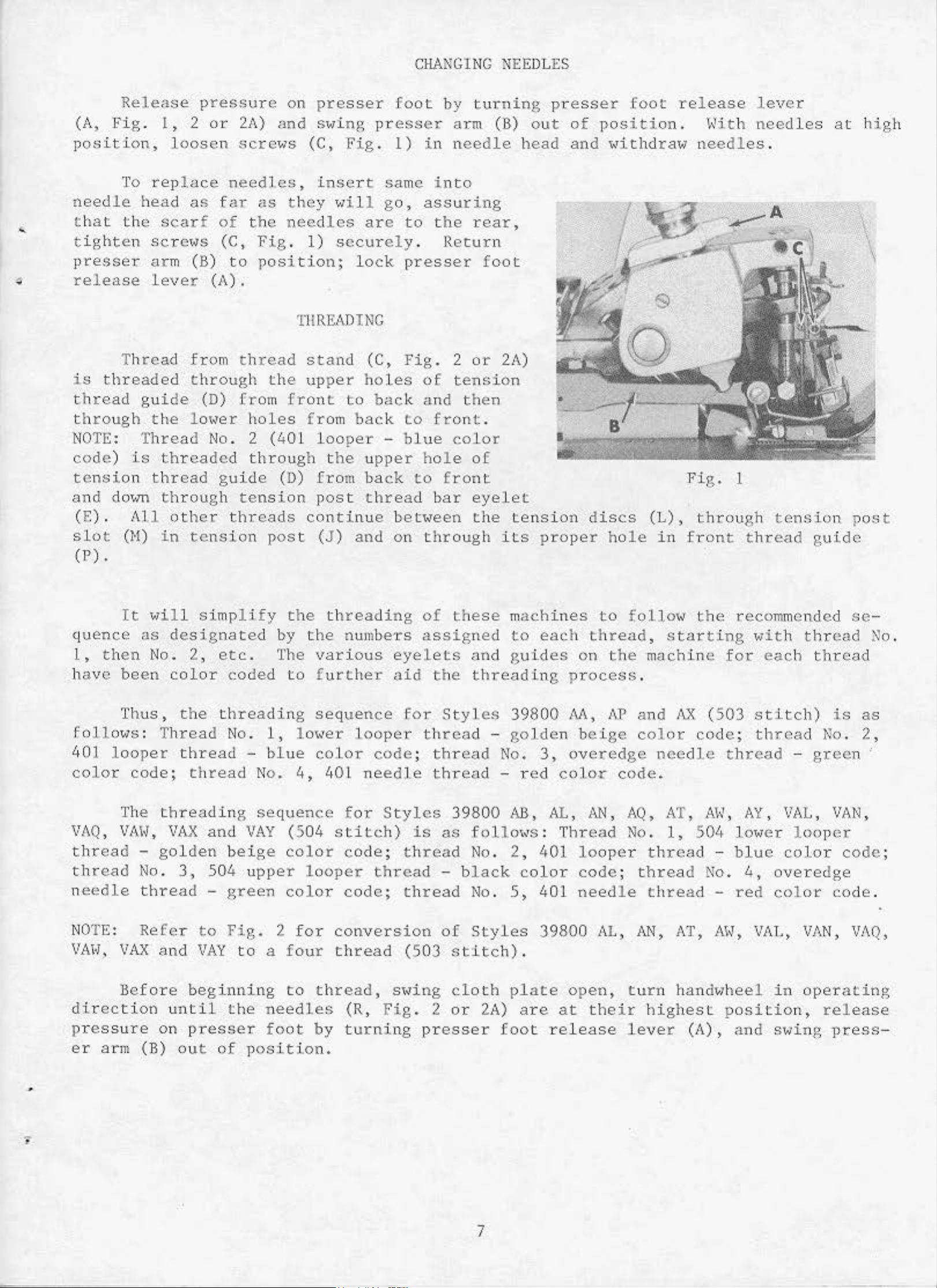
To
needle
t
hat
t
ight
head
the
en
presser
relea
is
thread
se
T
hread
threaded
guide
through
NOTE: T
code)
is
.
l,
2 o·r 2A)
loosen
rep
la
as
scar
sc
r ews
arm (B)
lever
from
through
the
lo,.er
hread
threaded
ress
ce nee
ure
scre•
dles,
on
and
,;s
presser
S>~ing
(C,
insert
far as they <Ji l l
f
of
the
(C,
to
(A).
needles
Fig
. 1)
position;
THREADING
t h
(D)
No. 2
read
the
from
holes
(40! looper
stand
upper
front
fr
om
through the upper
Fig.
are
secur
lock
(C, Fig.
holes
to
back
foot
press
l)
by
er
in
same into
go,
el
assuring
to
the
y .
Return
presser
of
bac
k and
to
front
-
blue
hole
turnin
arm (B)
needle
head
rear,
foot
2
or 2A)
ten~;ion
then
.
color
of
g
presser
out
•
I
of
and
foot
pos
iti
'~ithdraw
release
on.
\~j
needles
th
lever
needles
.
at
high
t
ensi
and
(E)
slo
(P) .
do
.
t (H)
quence
l,
then
have
Thus,
fo
llows
40
1
looper
color
The
VAQ,
VAH,
thread
thread
ne
edl
e
on
thread
<m
All
It
<Jill
as
No.
been
: T
code;
-
No
thread
guide (D)
through
other
in
tension
s i
tension
threads
mp
lify
designated
2,
etc.
color
the
hread
thread
thread
threading
VAX
coded
threading
No
. 1,
No. 4,
sequence
and
VAY
golden beige
. 3, 5
04
-
green
u
pper
from
post
conti
post
(J )
the
by
the
The
various
to further
sequence
1
0\~er
blue
color
40
(504
color
l oope~;
colo
r
back
thread
nue bet,.een
and
on
threading
numbe-rs
eyelets
aid
looper
code
l n
eedle
for
St
stitch)
code; t h
thr
code;
to front
bar
through
of
these mac
assigned
the
fo r
Styles
thread
;
thread
thread
yles
is
3
as
read
ea
d -
thread
eyelet
the
tension
its
to
and guides
threading
39800
-
golde
No. 3,
-
re
d coJ.o
9800
follo
No
black
No. 5,
AB,
«s: Thread
. 2,
401
color
401
discs
proper
hines
each
hole
to foll
thread, star
on
the
process
M,
n
AP
beige col
overedge
<:
cod
AL, AN, AQ,
No.
looper thread
code
need
;
le
Fig.
.
(L),
in
front
o"
through
the
t i
ng wit
machine for
.
and
AX
(503
or
code; thread
needle thr
e.
AT,
1,
A\~
50
'•
-
threa
thread
d No.
-
l
tension
thre
recommend
eac
ad
h
thread
h
guide
ed
thread
stitch)
No
ead
,
AY, VAL, VAN,
low
blue
4,
red
-
green'
er
looper
colo
overedge
color
r
post
se
is
. 2 ,
code
code
No.
as
;
.
NOTE:
VAH. VAX
direction
pr
essure
er a·rm
•
Refer
and
Before
until
on
(B)
to
Fig
VAY
to a
beginning
the
presser
<>u
t of p
. 2 fo r
four
to
needles
foot
osition
conversion
t h
read
thread,
(R, Fi
by
turning
.
of
Styles
(503
s'~ing
g.
2
pr
stitch)
cloth
or
esser
39800 AL,
.
2A)
plate
ar e
open,
at their
foot release
AN,
turn
highes
lever
AT,
hand~1hee
AI~,
t
(A),
VAT.,
l
in
position,
and
s"1ing
VAN, VAQ,
opera
ti
rele
pJ;ess
ng
ase
-
7
Page 2
SETTING
401 STITCH
REAR NEEDLE GUARD
(Continued)
lfuen
(E,
.102
to
pinch
but
not
needle
direction,
check
pinched.
be
and
Thread
feed
er
action
401
Fig.
mm)
5 . 56
thread
With
not
pinch
guard.
"hether
For
threaded
as
described
401
dog,
and
reset
toith
looper
9)
so
clearance.
mm)
deflect
convenience,
belo"
needle
thread
making
Lock
as
Looper".
throat
thread.
point
it
in
needle
at
needle,
in
Turn
needle
'''ith
sho\m
under
plate,
upper
is
at
the
touches
This
throat
SETTING
bottom
needle
handv7heel
complete
is
sere"
the
in (Fig.
Replace differential
knife.
but
guard
plate
eye.
position,
. 000
eye.
revolutions
disturbed
(H).
looper
parapraph
lower
Check
center
does
setting
seat.
Then
401 STITCH
to
. 004
Check
in
operating
may
2 or
"To
knife
cutting
not
lock
set
or
noto
2A
hold-
of
the
deflect
••i
ll
Hith
the
FRONT NEEDLE GUARD
front
inch
for
)
(.
clearance
to
needle
needle,
be
approximately
needle
guard
40
000
in
in
1
needle
to
place
. 102
bet"een
scarf,
.000
down
guard
mm)
set
position,
toith
40
to
.0
3/16
set
(G,
clearance.
401
looper
1
rear
04
to
screto
Fig.
needle guar
inch
7/32
guard
9)
Guard
and
(.000
inch
should
(F).
to
front
d
to
(4
. 76
not
touch
should
40
1
Asse
dogs
adjusting
should
locks
travel.
the
(A,
Feed
the
throat
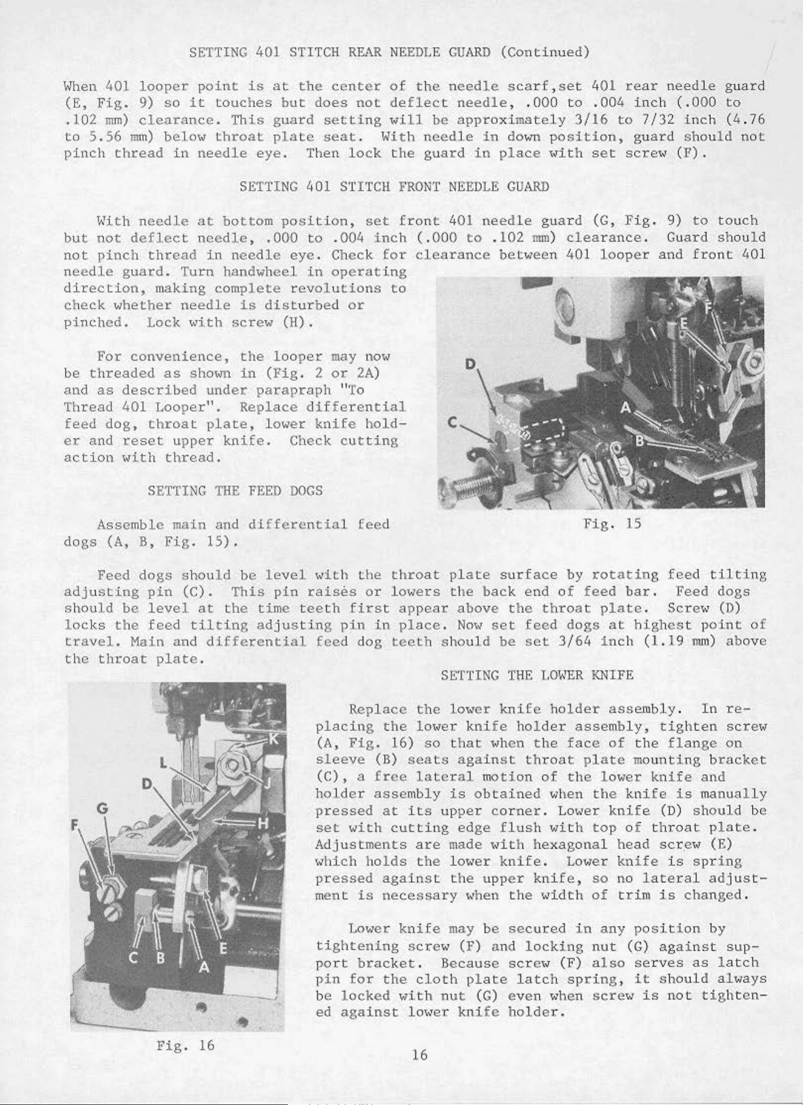
SETTING
mble main
B,
Fig.
dogs
be
Main
pin
level
feed
should
(C).
and
plate.
THE
and
15).
be
This
at
the
tilting
differential
FEED
differential
time tee
ad
DOGS
level
pin
just
t<ith
raises
i ng
feed
p
(A,
sleeve
(C),
holder
feed
the
th
first
pin
dog
Replace
lacillg
Fig.
a
throat
or
lov1ers
appear
in
place.
teeth
the
16)
(B)
free
assembly
seats
plate
the
should
SETTING
the
lotoer
lateral
so
lo"er
that
is
surface
back
above the
Noto
against
set
klli
fe
"h
m
otion
obtained
end
feed
be
set
TilE
knife
holder
en
throat
of
throat
3/64
LO\mR
holder
the
of
vlhen
Fig.
by
rotating
feed
plate.
dogs
assembly,
face
the
at
in
ch
KNIFE
assembly
of
plate
loV~er
the
15
feed
bar.
highest
(
the
mounting
kllife
Feed
Sere•<
1.19
tightell
flallge
knife
is
tilting
point
mm)
.
In
brack
and
manually
dogs
(D)
above
re
-
screto
on
of
et
pressed
set
Adjustments
"hich
pressed
m
tightening
port
pin
be
ed
·
Fig.
16
~·--·
with
ent
Low
for
locked
against
is
brac
at
its
cutting
holds
against
necessary
e~:
knife
scr.e«
ket.
the
Vlith
lo,.er
are
the
cloth
16
upper
edge
made
lo"er
t
he
may
(F)
Because
nut
knife
corner
'•ith
upper
t<hen
be
and
plate
(G)
flush
hexagollal
knife.
knife,
the
secured
locking
scre"'
latch
even
holder.
. Lo<•er
Vlith
Lotoer
"'idth
in
(F)
spring
when
knife
top
so
of
any
nut
also
scre
of
head
knife
no
lateral
trim
position
(G)
serves
,
it
w
is
(D)
throat
scr.e
is
is
changed
against
should
not
should
p
late
t<
(E)
spr
ing
adjust-
.
by
sup-
as latch
altoays
tighten
be
.
-
Page 3
SETTING
THE
UPPER
KNIFE
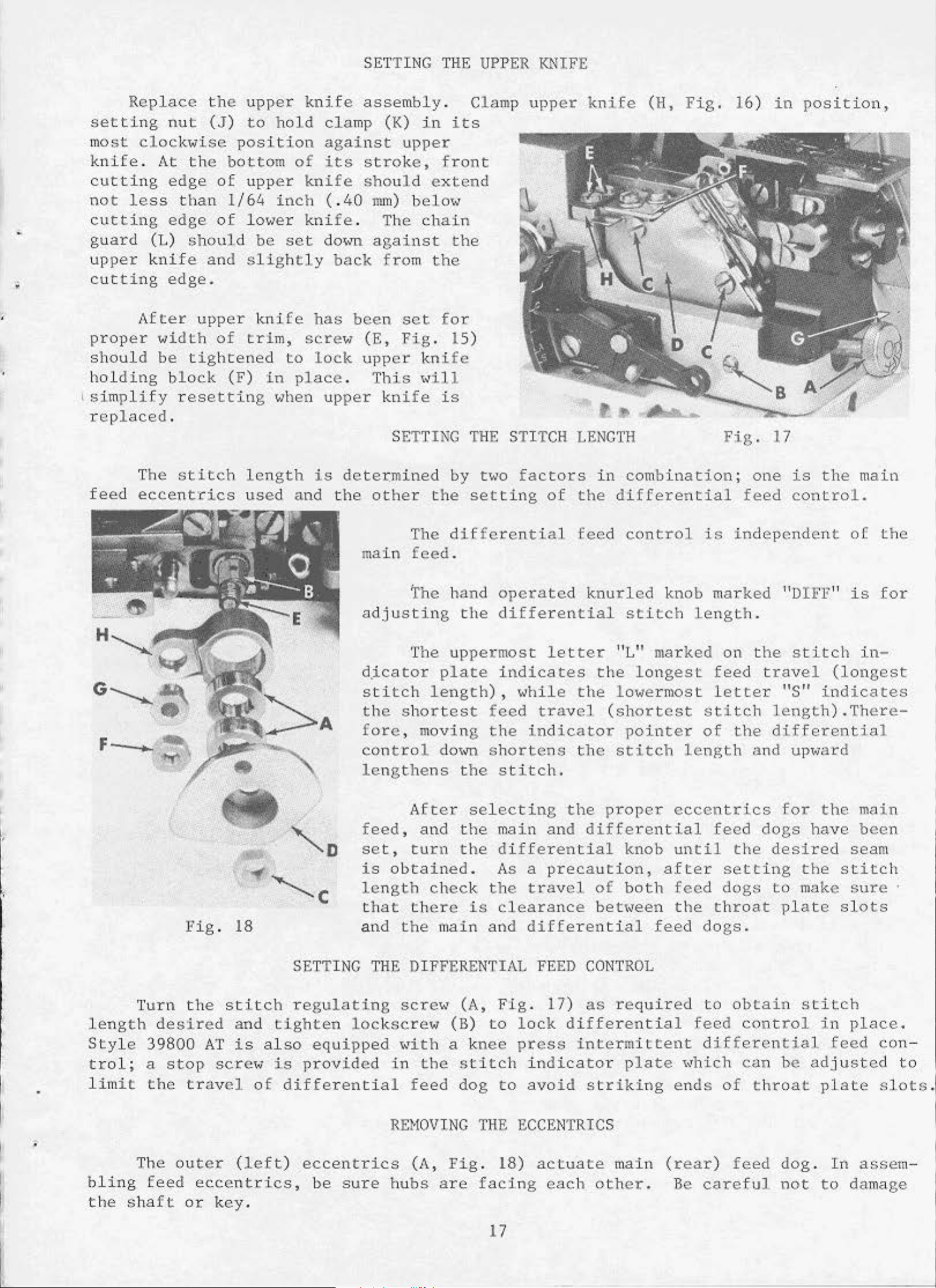
Replace
setting
most
knife
cutting
not
cutting
guard
upper
cutting
;
proper
should
holding
1
simplify
replaced.
less
nut
clockwise
.
At
edge
edge
(L)
knife
edge.
After
<'Jidth
be
bl
the
(J)
the
than
should
and
upper knife
tightened
ock
resetting
upper
to
position
bottom
of
upper
1/64
of
lo~1er
slightly
of
trim,
(F)
knife
hold
of
knife
inch
knife
be
set
sc;rev7 (
to
in place
~>hen
clamp
against
its
( .
40
do<m
back
has
lock
been
.
upper
assembly
(K)
upper
stroke,
should
nun)
. The
against
from
set
E,
Fig
upper
This
knife
SE
.
in
its
front
extend
bel.Oiif
chain
the
the
for
. 1
5)
kni
fe
•<ill
is
TTING
Clamp
THE
STI
upper
TCH
knife
LENGTH
(H,
Fig.
16)
Fig.
in
position,
17
'·
feed
The
eccentrics
stitch
length
used
is
deter.mined
and the
other
The
main
adjusting
d
.ic
stitch
the
fore,
control
lengthens
feed
set,
feed
The
T
he
ator
shortest
moving
After
,
and
turn
by
two
the
length),
setting
dif
ferential
.
hand
the
uppermost
plate
do•m
the
selecting
the
the
factors
of
operated
differential
letter
indicates
,,,bile
feed
the
shortens
stitch.
main
differential
travel
indicator
and
in
combination;
the
feed
the
the
the
differential
control
knurled
stitch
"L"
the
lo(o]e
(shortest
pointer
stitch
pro
differential
knob
knob
marked
longest
rmost
lengt
per ecc
until
is
independent
marked
length.
on
feed
letter
stitch
of
the
h a
entrics
feed
the
one
feed contro
the
is
the
"D
IFF" is
stitch
trave
length).There-
differential
nd
dogs
desired
l
"S"
for
indicates
upward
the
have
main
l.
of
in
(long
main
been
seam
the
for
-
est
leng
Sty
l e
trol;
limit
bling
the
Turn
th
des
39800
a
stop
the
The out
feed
sh
aft
Fig
.
18
the
ire
travel
or
stitch
d
and
AT
is
screw
er
(left
eccentrics,
key.
SETTING
regu
tighten
al
so
is
of
differentia
)
is
length
t
hat
and
THE
lating
lockscrew
equipped
provid
eccentrics
be
ed
sure
obtained.
check
there
the main
the
is
aod
DIFFERENTIAL
sere•~
«ith
in
the
l
feed
REHOVINC
(A ,
hubs
(B)
a
Fig
are
(A,
to
knee
stitch
dog
THE
.
facing
As a
clearance
Fig
to
precaution,
travel
differential
FEED
.
17)
lock
press
indicator
avoid
CONTROL
as
differential
intermittent
striking
ECCENTRICS
18
)
actuate
each
after
of
both
bet1~een
required
plat
main
other.
feed
the
feed
e
'"hich
ends
(rear)
Be
feed
setting
dogs
throat
dogs.
to
obtain
cont
dif
ferential
can
of
feed
careful
to
plate
rol
be
throat
dog. In
not
the
make
stitch
in
feed
ad
just
plate
to
stitch
sure
slots
place.
con
ed
slots
assem-
damage
-
to
.
17
Page 4
To
end
plate
support
401
looper
guide
looper
tion
tor
be
until
supplied
necessary
I€
take-up
(G)
and
change
(D);
plate
at
(H)
~olith
thread
key
eccentrics
(D,
Fig.
feed
feed
remove
(F)
accessible
extreme
cast-off
take
-up
slot
<dth
to
machine,
move
18)
driving
REMOVING
eccentrics,
screws
right,
support
(D)
in
ecc<mtric
hand wheel
are
unusually
from
connection
THE ECCENTRICS
(E)
with
permitting
fr
om
end
reach
bac.k
shaft
remove scre<,•s
and
scre1o1
chip
securing
chute
removal of
plate
is
behind
(F)
of
shaft
to.,ard
assembled.
the
eccentrics
and forth
tight
(E),
(H). T
it
fitting
may
hen
be
continue
(Continued)
(C,
Fig.
the
(G)
open;
the
Remove
(E).
Turn
front.
Using
and
slil~htly
,
in
addition
helpful
as
17)
extre
securing
me
turning
left
main
nut
hand"heel
hooked
withdra"
during
e
to
to
remove
originally
cast
right
end
handwheel
feed
(C,
in
thrust
Fig
operating
eccentric
eccentrics
xtrac
ti
on.
removing
nut
(F),
suggested.
-o
ff
of
to
.
18)
.
nut
ferrule
support
cas(
-o
ff
position
bar
and
direcextracIt
may
(C)
and
NOTE:
Thread
(B)
and
right
Control
clamp
as
required.
Before
Adjustments"
Fig.
screw
tightening
19
(C)
and
Retighten
nut (C,
.
then
collar
B
shift
scre«s
Fig.
the
18)
refer
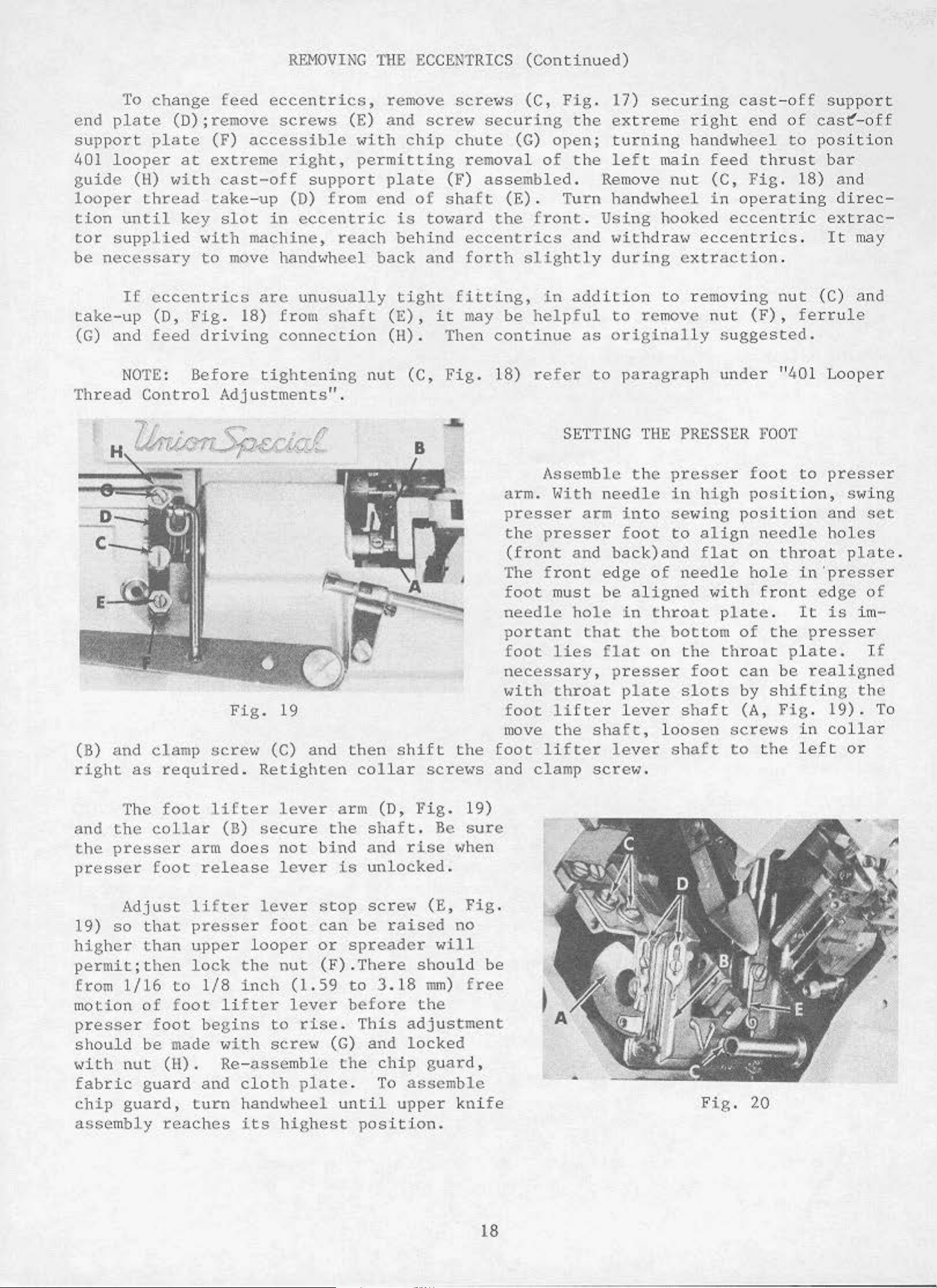
SETTING
Assemble
arm.
presser
the
(front
The
foot
needle
portant
foot
necessary,
with throat
foot
move
foot
and
~l
ith
presser
and
front
must
hole
lies
lifter
the
lifter
clamp
to
paragraph
THE
the
needle
arm
that the
in
foot
bac
edge
be
aligned
in
fl
at
presser
pl
lever
shaft,
le
ver
scre1o1.
to
k)
of
on
ate
under
PRESSER
presser
in
high
se~oling
to
align
and
throat
loo
flat
needle
"ith
pl
bottom
the
foot
slots
shaft
sen
shaft
throat
F
OOT
foot
position,
pos
iti
needl
on
hole
front
at
e .
of
the
can
by
(A,
be
shifting
Fig
screws
to
the
"401
to
on
e
Looper
presser
and
holes
throat
in·presser
ed
It
is
presser
pl
ate.
realigned
.
19).
in
collar
left
s
wing
set
plate.
ge
of
im-
If
the
or
To
The
and
the
presser
the
collar
presser
foot
Adjust
19)
higher
so
that
than
permit;then
from
motion
presser
should
«i
fabric
chip
th
1/16
of
foot
be
nut
guard
guard,
assembly
foot
lifter
arm
release
lifter
presser
upper
lock
to
1/8
foot
begins
made
(H)
.
and
turn
reaches
lever
(B)
secure
does
not bind and
lever
lever
foot
looper
the
inch
lifter
Hith
nut
(1.59
lever
to
r.ise.
sere"
Re-assemble
cloth
plate
hand"1heel
i.
ts
highest
arm
the
is
stop
can
or
(D,
shaft.
unlocked.
scre\J
be
spreader
(F).Tbere
to
3.18
before
This
(G)
the
and
chip
. To
until
position.
Fig.
Be
rise
(E,
raised
will
should
m
m)
the
adjustment
locked
guard,
assemble
upper
19)
sure
lohen
Pig.
no
be
free
knife
Fig.
20
18
Page 5
SETTING
THE
PRESSER
FOOT
(Continued)
NOTE:
presser
throat
plate
presser
fo
ot
is
•
Checl<
port
pl
ate
justment
rotating
l~ith
take
th
to
-up
rea
d
slightly
(long
Tractor
fo
ot
to
.
foot
lvhen
tilted
alignment
(B),
be
necessary,
handYlh
the
(A,
needle
Fig.
flat
advance
presser
be
1/16
Check
presser
do1m
Ylhich
eel
several
20)
parallel
to
in
front
t,01
of
looper
should
loosen
head
should
or
retard
foot
inch
ma
ke
f
oot
.
LOOPER
revolutions
at
the
be posit
to
to
(1.
59
sure
is
THREAD
thread
be
centered
screws
top
cast-off
take-up
be
set
nun)
401
and
raised
with
forward
overedge
to
CONTROL
take
- up
horizontally
(C), ·reposition
.
Tighten
of
its
ioned
stroke
to
support
later,
front
fro
m
front
needle does not
highest
position
ADJUSTNENTS
(A,
Fig.
screws
,
the
begin
taking
plate)
to
produce
t<all
20)
and
pl
ate
long
.
It
a
of
t,01
Y1all
of
and
in
slot
vertica
(B)
(C)
as
securely
flat
up
slack
may become
satisfactory
needle
401
s l
needle
interfere
front
o£
ll
y .
portion
cast
Should
- o
required
.
of looper
of
the loop
necessary
401
ot
in
slot
with
f£
Ylhil
thread
stitch.
of
sup
ad-
e
er
in
-
The
thread
amount
that
of
highest
required.
Set
this
position
needles
NOTE:
justments,
NOTE:
throat
Be
sure
plate.
adjustable
goes
thread
into
is
position.
pigtail
eyelet
slightly,
reach
their
When
ecce
al.,ays
For
lighter
the machine
eyelets
the
dra,m
They
highest
ntric
torque
is
(D,
stitch.
.
Initial
may be
(E,
Fig.
if
necessary,
position
cams
nu t
(C,
thread,
STARTING
threaded
Fig.
20)
Hhen
setting
lowered
20)
initially
'until
.
are
cast
changed
Fig
. 18)
of£
TO
according
partially
se.t
at
should
to
put
the
or looper
to
24-25
looper
OPERATE
to
the
determine
their
more
at
the
401
thread
threading
l
o••est
be
1/8
loope
r
six
looper
thread
in. lbs
1/32
the
position,
inch
thread
o'clock
thread
take-up
.
(28
inch
diagram
amo
unt
(3.18
into
position.
is
- 29
em/kg).
(.
79
(Fig.
of
looper
the
mm)
the
taut
maximum
from
stitch
•1hen
requires
mm)
belo.,
2
the
Vary
ad-
or
2A).
as
the
Set
thread
l~ith
needles
Fig
cast-off
thread
NOTE:
threa
tube
d
(T),
at
. 21
blade
required
Hhen
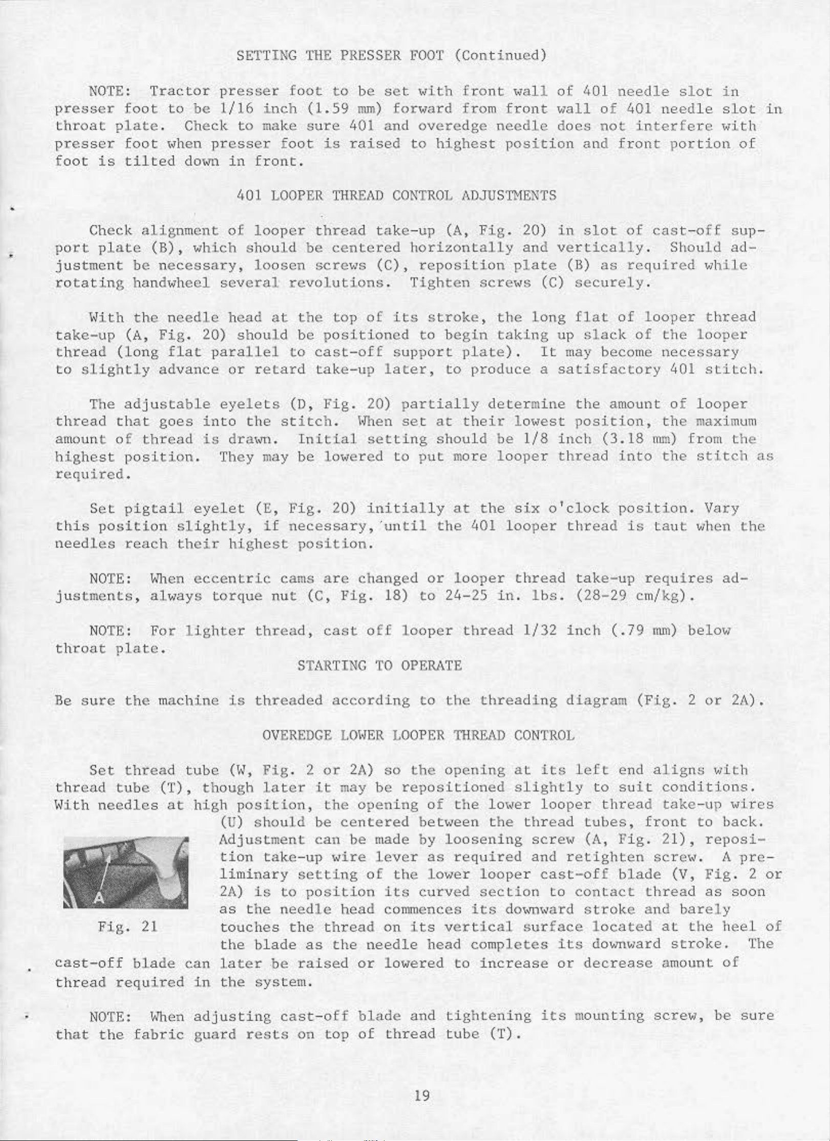
OVEREDGE
tube
high
(H,
thoug
(U)
Fig
h
later
po
sitio
should
Adjustment
tion
take-up
liminary
2A)
as the
is
to
need
touches
the
blade
can later. be
in
the
adjusting
system
cast-off
LOHER LOOPER
. 2
n,
or
it
may be
the
be
centered
can
2A)
opening
be
Hire
setting
of
position
le
head
the thread
as
the
raised
ne
or
.
blade
so
the
rep
osition
of
bet<·teen t
made
lever
its
the
by
as
lo"er
curved
commences
on
its
edle
head
loY7ered
and
THREAD
opening
ed
the
lo
1~er
he
loosening
required
looper
section
its
dot
vertical
completes
to
increase
tightening
CONTROL
at
its
left
slightly
looper
thread
sere<•
and
retighten
cast-off
to
contact
,•
m~ard
surface
its
or
its
mounting
end
to
suit
thread
tube
(A,
s ,
Fig.
blade
stroke
located
dov1m1ard
decrease
aligns ,,,ith
conditions.
take-up
front
2
scret~
thread
and
at
1),
(V,
bare
to
reposi
.
Fig
as
l y
the
stroke.
a
mount
sere.,,
be
"'ires
back.
A
pre
. 2
soon
heel
The
of
sure
-
-
or
of
that
the
fabric
guard
rests
on
top
of
thread
19
tub
e
('I').
Page 6
OVEREDGE
NEEDLE
TKREAD
CONTROL
~~ile
needle
thread
2A) should
ca
n be
sition,
below
more
adjus
the
the
strike-off
depending
sition
thread.
,
the
Adjust eyelet
With
mately
barely
les
the
horizontal
contacts
are
at
inside
stroke.
sewing on
is
dra
be
set
ted
up
finger
thread
holes
and
on
thread,
curved
needles
inside
down
of
positi
eyelet
materia
wn
on
l,
needle down
approximately
or
down
of
the
in
should
to
take-up
eyelet
be
material
section
of
bracket
UPPER
at
and
high
so
on,
(AH) •
position,
positioned,
front
wire
the
Usuall
check
needle
stroke.
in
the ce.nt
suit
set
and
conditions.
(AM)
(AL)
should
for
approximately
st
itch
length.
thread take-u
(AL)
f
on•ard
LOOPER
set
looper
with
of
rear
wire
y
all
the
left
of
loop
thread
Needle
er
to
\Hth the
be
the
504
1/8
p
(AM)
or
rean<ard
THREAD
thread
thread
take
the
er
left
thread
control
thread
upper
se
t approxima
stitch
With
to
port
. The 503
3/16
needle
should
to
CONT
ROL
eyelet
taut
- up
through
wire
take-up
should
as
follow
take-up
ion
needle
tely
inch
head
barely
meet
(AH,
eyele
(U).
wire
be
s:
(AN,
of
its
head at
l/32
stitch
(3
. 18
at
touch
these
conditions.
Fig .
t
holes,
Make
(U)
sure
does not
drawn on
Usually
Fig
slot,
low
though
est
inch(.79
requires
to
4. 76
highest
the
2A)
needle
approxi
when
needle
all
. 2
po
or
-
mm)
mm)
po
-
thread
need-
strike
d01m
it
-
Set
needle
should
\
-lith
thread
Style
operate
needle
thread
be
positioned
take-ups
tensions
39800
s
in
conjunction
thread
is
drawn on
to
AT
adjustable
with
and
eyelets
obtain
i s
equipped
'~ith
401
the
the
downstroke. Eyelet
bottom
set
desired
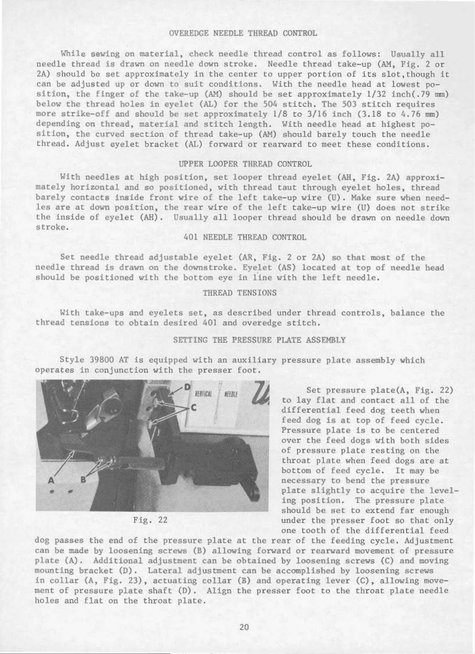
SETTING
the
NEEDLE
eyelet
eye
THREAD
,
as
401 and
THE
with
press
rWICil
an
THREAD
(AR,
in
line
TENSIONS
de
scribed
overedge
PRESSURE
auxiliary
er
foot.
11{111
CON
Fig
TRO
L
. 2
(AS)
with
under
or
2A)
located
the
thread
stitch.
PLATE
ASSEMBLY
pressure
Set
to
lay
flat
differential
feed
dog
Pressure
so
that
at
left
needle
controls
plate
pressure
and
feed
is
at
plate
most
top
of
needle
.
,
balance
assembly
plate(A,
contact
top
is
dog
to
of
teeth
feed
be
of
the
which
Fig.
all
of
when
cycle
centered
head
the
22)
the
.
A
dog
can
plate
pa
sses
be
made by
(A).
mounting
in
collar
ment
holes
of
and
the
Additional
bracket
(A,
Fig.
pressure
flat
Fig.
end
of
the
loosening
(D).
23) ,
plate
on
the
throat
22
pressure
screws
adjustment
Lateral
adjustment
actuating
sha
ft
(D).
pJate.
plate
(B)
can
collar
Align
at
allowing
be
obtained
can
(B)
the
the
rear
forward
be
accomplished
and
operating
presser
over
of
throat
bottom
the
pressur
plate
of
necessary
plate
ing
should
under
one
by
slightly
position.
be
the
too
th
of
the
or
rearward
loosening
foot
feed
e
plate
feed
to
set
presser
of
feeding
by
lever
to
the
dogs
restin
when
feed
cycle
bend
to
the
acquire
The
to
extend
foot
the
different
cycle.
movement
screw
s (C) and moving
loosening
(C),
th
roat plate
<Jith
both
g
dogs
.
It
pressure
pressure
far
so
Adjustment
of
screws
allowing
sid
on
the
are
may
the
plate
enough
that
ial
pressu
move
needle
es
at
be
level
only
feed
re
-
-
20
Page 7
SETTING
THE
PRESSURE
PLATE
ASSE~lliLY
(Continued)
Adjust
clearance
foot
contact
Thrust
in
the
the
loosening
spanner
in
the
( .
762
enough
movable
presser
bottom.
collars
pressure
shaft
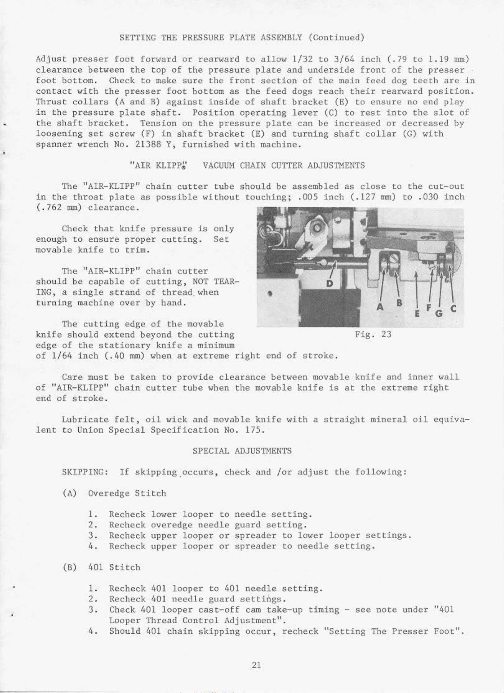
The "AIR-KLIPP"
throat
mm)
Check
to
between
Check
1~ith
wrench
knife
the
bracket.
set
clearance.
ensure
screw
plate
that
to
foot
(A
plat
No.
knife
for"ard
the
presser foot
and
"AIR
proper
trim.
top
to
make
B)
e
shaft.
Tension
(F)
21388 Y,
as
in
KLIPP,&
chain
possible
pressure
cutting.
or
of
the
sure
bottom
against
Position
on
shaft
furnished
cutter
rear"ard
pressure
the
inside
the
bracket
VACUU"H
"lithout
is
front
as the
pressure
with
tube
only
Set
to
allow
plate
section
feed
of
shaft
operating
plate
(
E)
and
machine.
CH
AIN
should
touching;
CUTTER
be
1/32
and
dogs
bracket
le
can
turning
assembled
.005
to
underside
of
the
reach
ver
(C)
be
ADJUSn 1
inch
3/64
main
(E)
increased
shaft
inch
front
their
to
to
rest
collar
ENTS
as
close
(.127
feed
ensure
(.
79
to
of
the
dog
rearward
into
or
teeth
no end
the
decreased
(G)
to
the
mm)
to
1.19
presser
are
position.
play
slot
with
cut-out
.030
inch
rom)
·
in
of
by
The "AIR-KLIPP"
should
ING,
turning
knife
edge
of
1/64
of
"AIR-KLIPP"
end
le
nt
be
a
single
The
should
of
Care
of
stroke
Lubricate
to
capable
strand
machine
cutting
extend
the
inch
Union
stationary
(.
must
.
Special
of
over
edge
40
mm)
be
taken
chain
felt,
chain
cutting,
of
by
of
beyond
knife
when
cutter
oil
Specification
cutter
thread
hand.
the
to
~<ick
mov
the
at
provide
tube
NOT
. when
a m
extreme
and movable
SPECIAL
TEAR-
able
cutting
inim
um
clearance
when
No.
right
the
ADJUSnlENTS
mov
knife
175.
•
end
of
between
able
"ith
stroke
movable
knife
a
Fig.
.
knife
is
at
straight
A
23
the
extreme
mineral
B
and
E F G C
inner
oil
wall
right
equiva
-
S
KIPPING
(A)
Overedge
1.
2.
3.
4.
(B)
401
1.
2.
3.
4.
:
If
skip
Stitch
Recheck lm<er
Recheck
Recheck
Re
c.heck
Stitch
Rec
heck
Recheck 401
Check 4
Looper
Should
ping.
overedge
upp
upper
401
01
looper
Thread
401
occurs,
looper
er
looper
looper
looper
needle
Control
cha
in
check
to
needle
to
guard
cast-off
skipping
guard
or
or
401 n
Adjustment".
and
needle
setting
spreader
spreader
eedle
settiilgs.
cam
occur,
take
/or
setting.
adjust
to
lower
to
needle
setting.
-up
recheck
.
timing
"Setting
the
looper
setting.
-
see
following:
settings.
note
The
Presser
under
"401
Foot".
21
Page 8
TO
REHOVE
CRANKSHAFT
Crankshaft
1.
2.
Drain
base
Remove t
.
can
oil
op and
be
withdrawn
by
removing
easier
plug screw
bot torn cov
ers
if
of
these
located
machine
steps
on
.
are
back
followed:
of
machine
T
near
bottom
R
edge
p
of
'
'
'
'
'
3 . Re
4.
5.
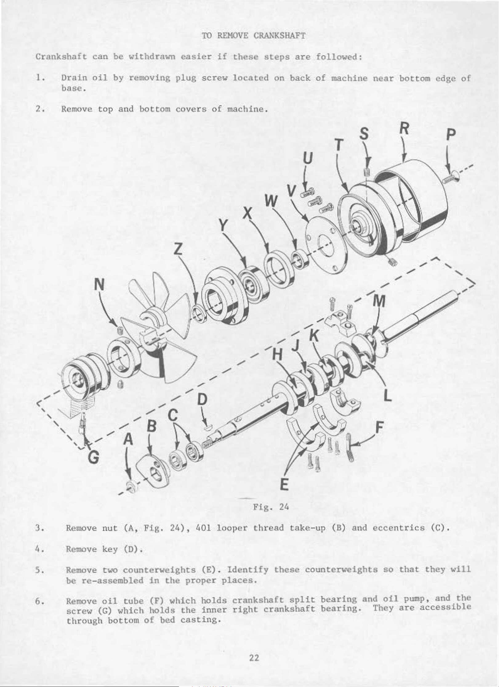
Remove k
Remove two
be
move nut
re-assembled
(A,
ey
(D).
counterweights
Fig
in
. 24) ,
the
proper
401
l oop
(E). Identify
er
places.
Flg.
t h
read
E
24
take-up
these
( B)
counterweights
and
ecce
so
nt
that
ri
cs
(C).
they
••ill
6.
Remove
screw
through
oil
(G) which
bo
tube
tto
m
(F)
holds
of
which
bed
the
cas
holds
inner
t i ng .
crankshaft
right
crankshaft
22
spli
t
bearing
bearing.
and
oil
They a r e
pump,
accessible
and
the
Page 9
TO
REHOVE
CRANKSHAFT
(Continued)
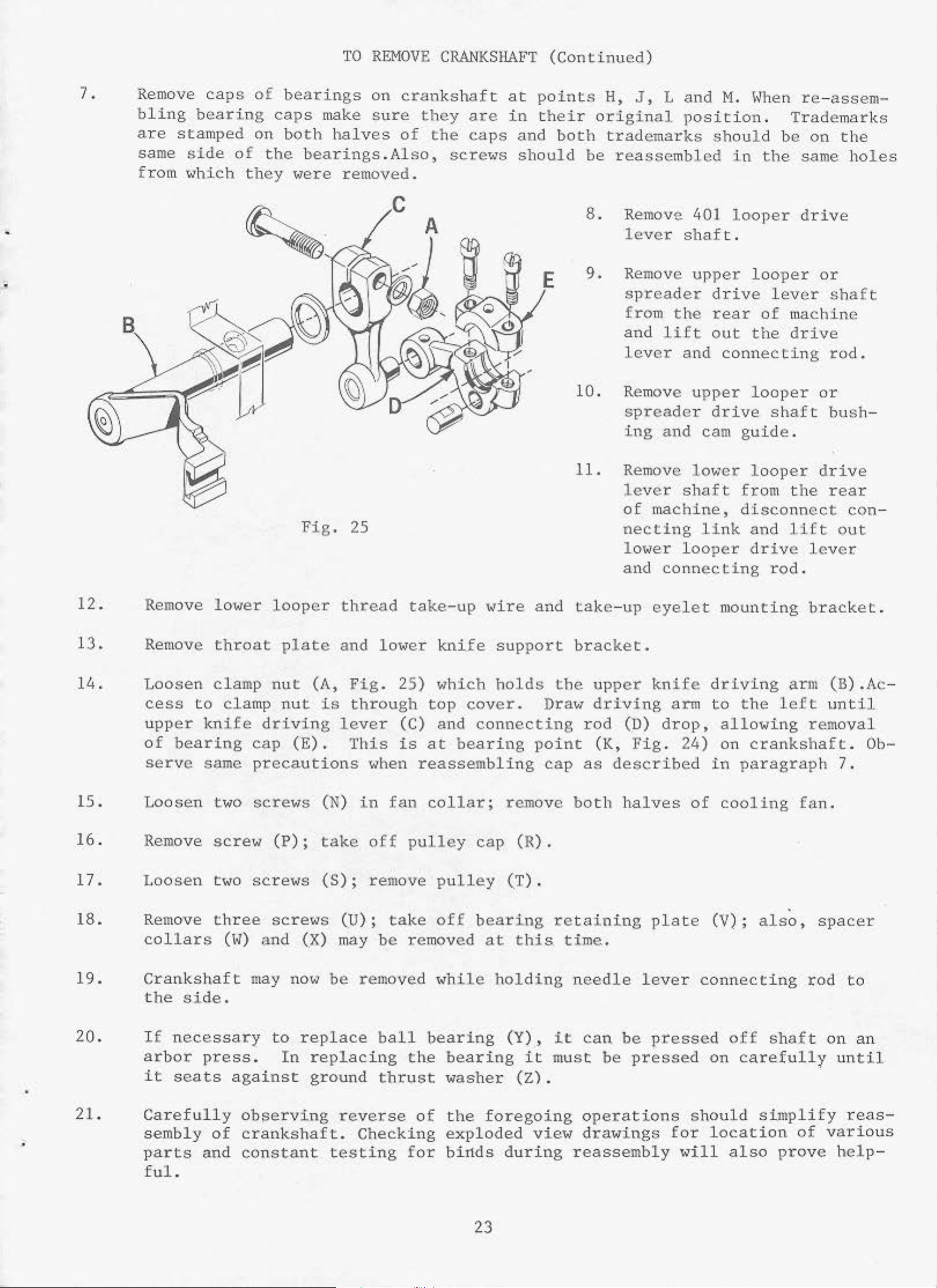
7.
•
Remove
bling
are
same
fr
stamped
side
om
which
caps
bearing
of
they
of
bearings
caps
on
bo
the
on
th
make
halves
sure
bearings.Also,
were
removed.
crankshaft
of
they
the
are
caps
screws
at
points
in their
and both
should
H,
J,
original
trademarks
be
reassembled
8.
Remove 401
lever
9. Remove
spreader
from
and
lever
10.
Re
move
spreade
ing
L
and
position
shaft
upper
the
lift
and
upper
r
and
M.
l~hen
should
in
the
looper
.
loo
drive
rear
out
of
the
connecting
looper
drive
cam
guide
re-assem-
.
Trademar
be
same
d
per
lever
ma
drive
shaft
.
on
the
rive
or
shaft
chine
rod.
or
bush
ks
holes
-
12.
1
3.
14.
15 .
Remove
Remove
Loosen
cess
u
pper
of
to
bearing
serve
Loosen
lo•1er
throat
clamp
clamp
knife
same
two
Fig.
looper
plate
nut
nut
(A,
is
driving
cap
(E).
precautions
scre•1s
(N)
25
thread
and
lower
Fig. 25)
through
lever
This
(C)
is
"hen
in
fan
take-up
kn
ife
which
top
and
at
bearing
re
assembli
collar;
~~ire
and
support
holds
cover
. Draw
connecting
point
ng
remove
the
cap
11.
Remove
l
of
necting
lower
and
tal<e- up
bracket.
upper
driving
rod
(D)
(K, Fig.
as
described
both
halve
ever
shaft
machi
lo
connecting
eyelet
knife
a:rm
drop,
24
s
lower
ne,
link
oper
mounting
driving
to
allowing
)
on
in
of
cooling
looper
drive
from the rea
disconnect
and
drive
rod
Uft
lever
.
out
bracket.
t he
arm
left
(B) .Ac-
until
removal
crankshaft.
paragraph
fa
7.
n.
r
con
Ob-
-
16. Remove
17.
18.
L
oosen
Re
move
collars
19.
20.
Crankshaft
the
I£
side.
necessary
arbor
it
seats
2
1.
Carefully
sembly
p
arts
ful.
screw
t\<O
three
(
H)
press.
agai
observing
of
crankshaft.
and
constant
(P);
screws
screws
an
d
may
no.,
to
In
nst
take
(S);
(U);
(X)
may
be
removed
replace
replacing
ground
reverse
Checking
testing
off
rem
ove pull
ta
be
b
all
thrust
pulley
ke
off
removed
\<hile
bearing
th
.e
be
aring
washer
of
the
exploded
f
or
bii1ds
c
ap
(R) .
ey
(T).
bearing
at
this. time
holding
(Y),
it
(Z).
foregoing
view
du
ring
retaining
.
needle
it
mu
can
st
o
be pressed
be
pressed
pera
tio
drawings for
reassembly
plate
l
eve
(
V);
r c
onnecting
off
on
also
shaft
care.fully
ns should simplify
location
"ill
also
pro
.
,
spacer
rod
of various
ve
on
un
help
to
an
til
reas
-
-
23
Page 10
TO
RE~lOVE
CRANKSHAFT
(Continued
)
22.
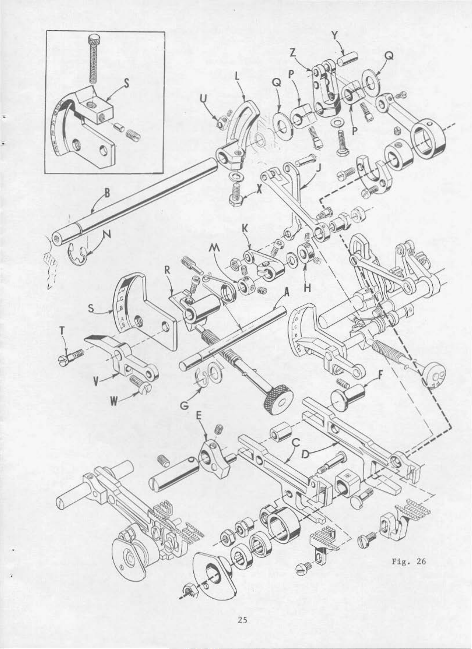
l.
2.
3.
4.
Before
gaskets.
to
prevent
ADJUSTING
Assemble
shaft
(B);
Thrust
thrust
and
differential
Thrust
against
the
The
bed casting
differential
reassembling,
Coat the
oil
leakage.
INST
parts
as
including
feed
rear
bars
of
(C
feed
feed
the
the
feed
recess
control
and
feed
thoroughly
oil
dra
in
No. 1
RUCTIONS FOR
illustrated
feed
and
bars
bar
bar
D)
against
'~ith
guide
shaft
in
the
bed
tightened
control
plug
Crane
to
s.
tilt
(A)
casting
securely
link
clean
"ith
Lead
QUICK
feed
differential
adj
(F).
assuring
.
(J)
and
a
dry
sealing
Seal
STITCH
control
ust
ing
that
Collar
.
and
differential
the
compound
is
recommended.
FEED
shaft
thrust
pin
and
retaining
(H)
top
DRIVE
(A,
feed
should
and
bo
before
HECHANISH
Fig
.
guide
leveling
ring
be
feed
ttom
covers
reassembling
26)
on
and
bed.
(G)
thrusted
control
and
feed
Align
lever
is
flush
against
leve.r (K)
rock
and
(E)
5.
6.
a.
must
and
Feed
be
in
secured
rock
(N) up<Oards
cure
(Q)
A
control
See
provided
against
bind
inser
shaft
could
lever
t
in
eliminate
Hove
ential
dif
ferent
feed
alignment
in
po
shaft
and
(B)
the
thrusted
in
bed
occur
actuator
for
configuration
plate
binds
.
ial
drive
sition
(B)
this
in
"S"
DI
feed
se
'~ith
differential
by
should
against
position
casting.
the
differentia
(R)
for
FFER
its
ENTIAL
segment
gme
nt
(L).
collars
be
positioned
if
the
of
mounting
FEED
sliding
(H
t
he
by
thrusting
indicator
(S)
on
CONTROL
feed
and
driv
N) .
'<lith
dif
fe
rential
l
feed
drive
plate
Style
sere'~
ADJUST}ffiNT
b
lock
e
the
collars
39800
(T)
(U)
to
to lo.,
segment
opening
feed
drive
(P) against
lever
(S)
is
AT.
allo••
est
(L) to
of
the
segment
(K)
not
and
properly
Oversize
repositioning
position
avoid
binding
retaining
(L
) .
thrust
"ashers
differential
aligned.
holes
are
and
in
differ
ring
Se-
-
b.
c.
a.
b.
c .
d.
R
otat
p
ointer
Clamp
Hove
e
differential
is
the
differen
differential
Turn
Loosen
O
per
feed
movement.
the
differential
ate
differential
drive
stitch
at
th
e bo t
indicator
tom
pointer
DIFFERENTIAL
tia
l
feed
stitch
hand,~heel
in
dicator
until
feed drive
stitc
segment
clamp
indicator
of
scale.
(V)
FEED
segment
pointer
the
sere'~
feed
h
indicator
with
DRIVE
sliding
bar
segment
(X)
>~hen
pointer
screw
SEGHENT
block
(V)
(H).
ADJUSTNENT
(U)
(V) clockwise.
is
in
its
clamp
pointer
the
scre1~
(V)
differentia
counterclockwise
to
m
top
ost
rear
po
sit
position.
(X).
and
tighten
l
feed
until
ion
by
rotating
differential
bar
(D)
t
he
shm~s
no
24
Page 11
y
v
'
'
·r
E
25
Fig.
26
Page 12
IJI
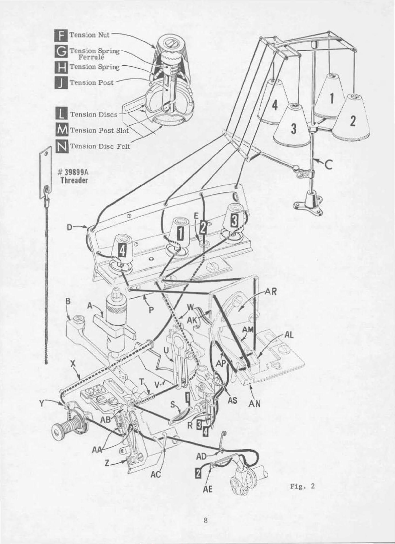
Tension
Nut
[!J
Tension Spring
Ferrule
m Tension Spring
~
Tension
Tension
fi]
Tension
IIJ
Tcns
#
39899A
Threader
Post
Discs
Post
ion Disc
1
2
Slot
Fig. 2
8
Page 13

D
IFFERENTIAL
FEED DRIV
E L
EVER
a.
Standard
feed
ing,
drive
move
ILLUSTRATIONS
This
of v
th
eir
ario
actual
found a
ieces
p
Numbers
position
ordering
catalog has
us
secti
position
listi
ng of
require
in
of
t h
parts
Component
cated
by
indenting
location
leve
pin
r (Z) .
(Y)
been a
ons
of
in
the
d
in
t he
the fi
at
part
rs
in
. Always
parts
the
of
ir
of
to
link
For
lower
pin
longer
hole
ORDERING
the
mechani
the mach
part
part
t
colu
s with
ic
rran
ged to
sms are
ine .
th
ular vie
mn
are
the illustration
use
the
part
sub-assemblies
descriptions
(Y)
is
to
differen
of
leve
r (Z) .
REPAIR
simpl
sho
i fy
wn
On the page
ei r
pa
r t numb
1< being sho
reference
.
Reference
number
which
under
lis
can
the
be
in
ti
al
PARTS
orderin
so
ers
••n.
numbe
ted i n
be
des
t he upper
fee
d
tr
avel
g repai r
that
opp
, d
rs
the part
osite
escription and
onl
y,
number s shou
th
e second column.
furnished
criptio
n
hole
,
of
such
parts
s m
ay
differe
as
for
. Exp
be
loded
see
n
gather
n
the illustration wil
th
e number
and m
for
of
erely
ld
never
repairs
the main
indica
be
used
are
sub
-assembl y .
tial
-
view
s
in
l be
of
te the
in
indi
Example:
Ref.
No
.
18
19
20
21
22
23
24
25
26
27
Part
No
.
294
77
m·
29
4 77
~
Ill
39852 A
77
22587
M
39516-625
39516-626
39516-
30-
51
627
106
-228
39541 A
C067
258
E
Blk
Blk
.
.
Cranksha
for
Sty
ft
les
Crankshaft
for
al l St
Needle Dri
Screw - - - - - - - - - - - Screw - - -
Needle
Needle
Needle
Wood
Vent
Feed
Cork P
Nut - - - - - - - - - - - - -
D
escription
and Needle
39800
a1
1d Needle
yles
AA
except
vi ng Connecti ng
Bearing
Bearing
Bearing
, .0625
, .0626
, .0627 i
Plug, birch
Plug
Driving
lug
- - - - - - - - - - - - - - - - Ecce
- - - - - - - - - - - - - - - - - - -
Driving Co
an
d AB - - - - - - - - - - - - - - 1
Driving
39800
nnecti ng Rod Assembl
Connectin
AA
and
Rod Asse
g Rod Assem
AB-
mb
- ly
- - -
y,
bly
- - - 1
- - - 1
- - 2
r-
-
-
-
-
inch
in
nch
(1. 588
ch (1.590
(1 .593
mm)
mm)
mm)
diameterdiameter
diamete
- - - - - - - - - - - - -
ntric
Key
- - - - - - - -
- - -
Am
Req
,
-2
-28
-2
t.
.
1
8
8
1
1
1
1
1
I
11
t h
cat
alog
arts
p
ed
in
ration.
t
in
this
only
, no spe
!or
lhe
Al
the
book.
the
\./hen
too small
distinguis
ose
the va
desc
back
part
the con
for
h one
cas
es
cific
rious
ription
of the
This
number
s t
ructi
a compl
part
•<here a
usa
ge
par
1~ill
machines
and,if necessa
will
is
ete
from
book
facilitate
known
on pe
ca
will
.
rmits,
talog
anoth
t
is
common
to
be menti on ed
a rc not the
sa
r y, t he
be
found a
locating
IDENTIFYING PART
each
stampi.ng a
er
th
at
is
pa
rt i s
re
simil
al
l
the
in the
me, t
he
descr
speci
differences
nume
the
rical
illust
S
sta
mp
ident i fi
ar
in
appea
machin
iption.
fic
will
index
rati
ed
ed
on and
with
by
ranc
es covcr
usa
ge
e.d
How
•~
ill
eve
by
r,
be me
be s hown i n t he
of
all
the
parts
description
it
s
part number . Parts
l etter
sym
bol s
e .
this
when
nti
illu
sho
wh
which
th
on-
s-
'm
en
e
26
Page 14
IDENTIFYING
PARTS
(ConLinued)
Part
IMPORTANT!
WHICH
PART
Success
UNION
aries
Sl?ECTAL
and
:;clentifi.c
durability
Prices
are
wise
forwarded
directed.
numbers
IS
ORDERED
in
represent
0~
the
Repair
authorize
principles,
ore
assured.
are
strictly
f.o.b
A
charge
ALL
ORDERS,
.
operation
Parts
d
distributo
and
net
.
shipping
is
the
same
PLEASE
USE
as
GENUlNE
of
these
furnish
rs.
are made
cash
and
point.
made
to
part,re~ardless
HCLt:DE
ed
They
~'i
Lh
REPAIR
machines
by
ore
utmost
Lhe
desig
PART
NAME
PARTS
can
be
Union
ned
precision.
TERMS
subject
Parcel
cover
postage
to
Post
change
shipments
and
of
catalog
AND
STYLE
secured
Specia
l
according
~laximum
without
are
insurance.
in
which
OF
MACHINE
only
l~ith
Corporation,
to
the
mofiL
ef
Ciciency
noLic:e.All
insured
unless
they
appear
FOR
genuine
iL
subsidi
approved
nnd
shipments
other-
.
-
Torque (measured
a
distance
driver,
of
torque
All
unless
hand
as
The
by a
ecc.Many
'~ill
sL
r.:tps and
otherwise
tightly
screws
lever
of
these
tighten
eccentric"'
noted.
as
possible,
requiring
TORQUE
in
inch-pounds)is
(in
inches
devices
the
part
should
All
other
unl
a
specific
or
are
to
ess
REQUIRP.l-!E:XTS
a
rotating
feeL)
.
This
availnbJe,
the
nuts,
correct
be
ci.ghtened to
bolts,
otherwise
torque,
amou
noted
will
force
is
nccomplished
"hich
nt
'<ben
and
(in
no
19-21
screws, etc.,
.
be
indicated
pounds)
by a
set
at
applied
wrench,
Lhe
tighter.
inch-pounds
should
on
i>e
th~
through
s"rew
proper
nmount
(22-zt,cm/kg)
LighLened by
picture
plate
.
27
Page 15
i
9
1
39
28
Page 16
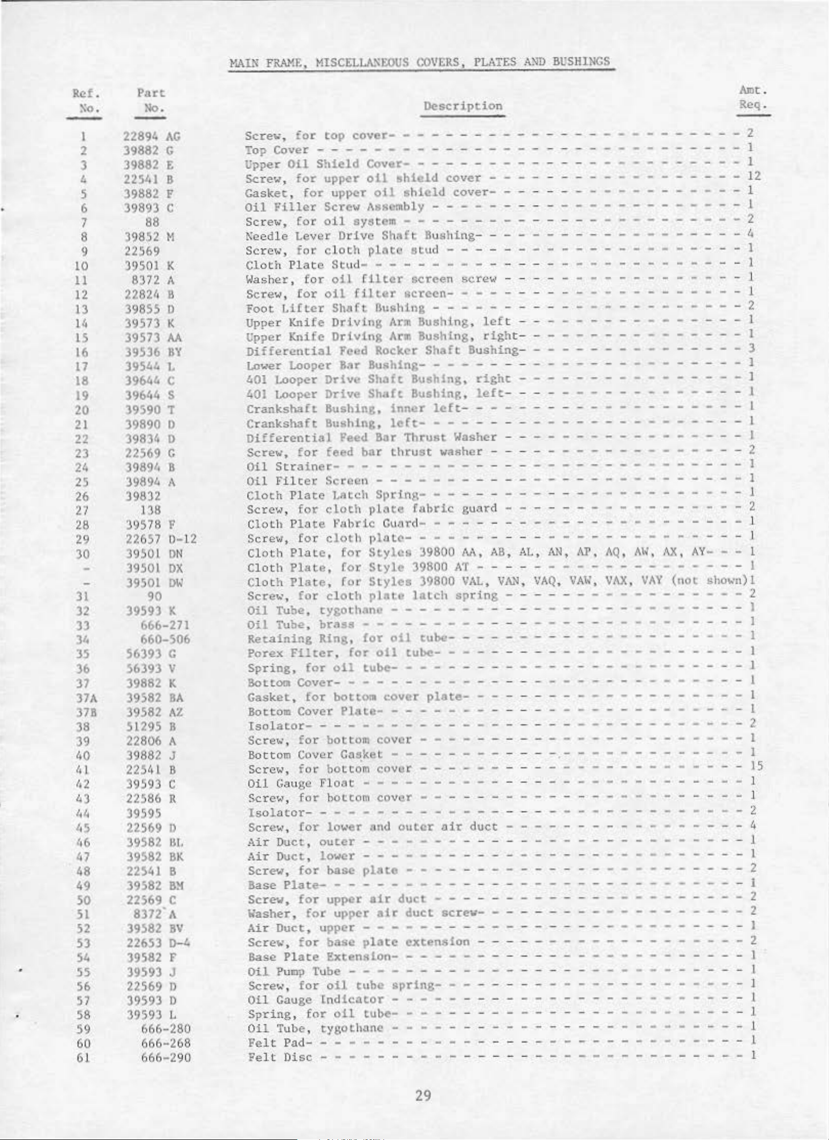
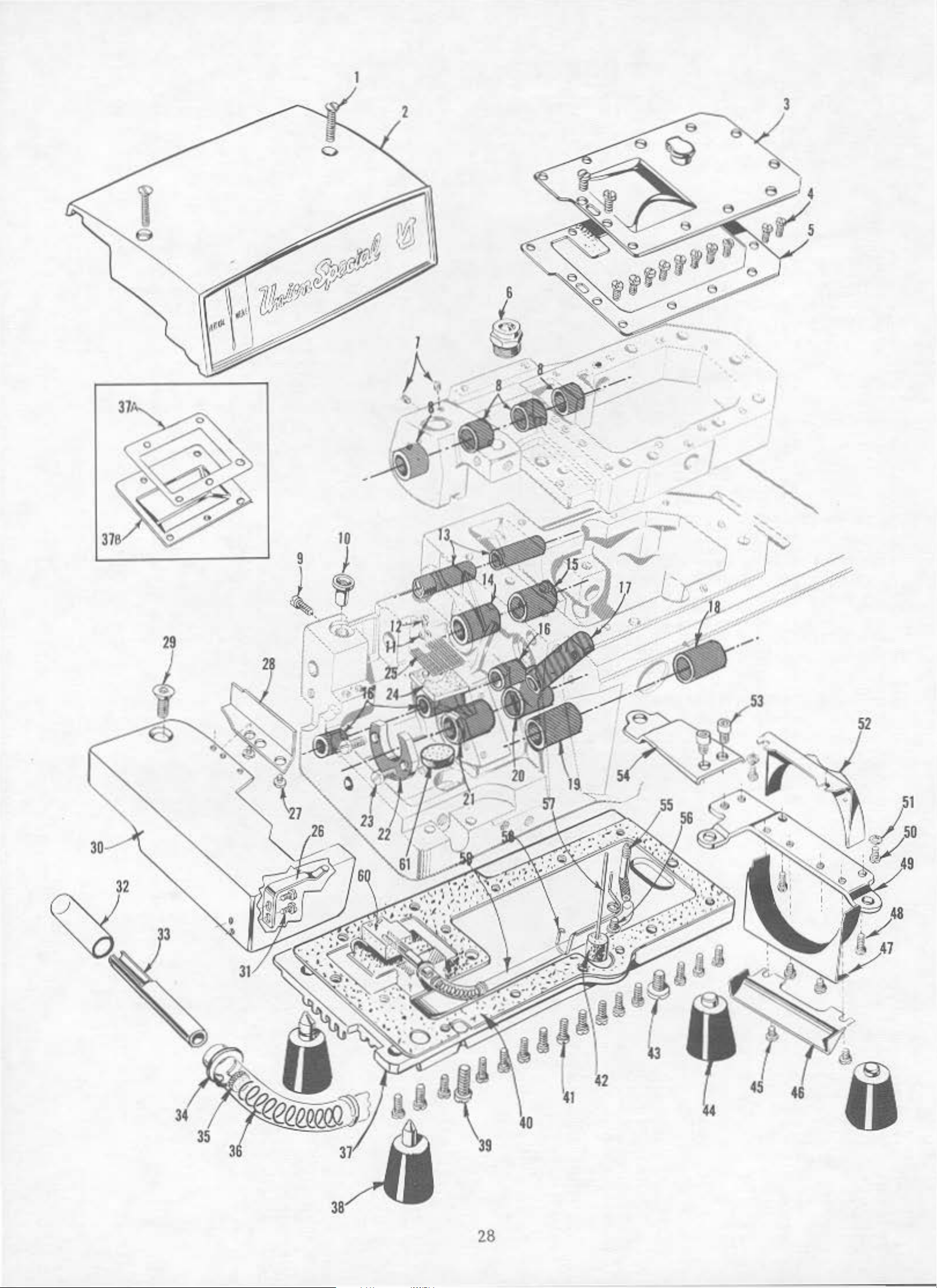
MAIN
FUM",
MISCELLA~t;OUS
COVERS,
PLATES
A~D
llUSHlNGS
Ref.
xo.
Part
llo.
Description
Amt.
Req .
-
I
2
3
~
5
6
7
8
9
10
11
12
13
14
15
16
17
18
19
20
21
22
23
24
25
26
27
28
29
30
31
32
33
34
35
36
37
37A
37B
38
39
40
ld
1
12
~3
41•
ll5
46
47
48
49
50
51
52
53
54
•
55
56
57
58
59
60
61
22894
AG
39882 c
39882 t
22541 B
39882 F
39893 c
88
39852 M
22569
39501 K
8372 A
22824 B
39855 D
39573 K
39573
39536
39544
AA
BY
I.
39644 c
39644 s
39590 T
39890 0
39834 0
22569 c
39894 B
39894 A
39832
138
39578 F
22657 L
39501
39501
39501
>-12
ON
ox
OW
90
39593 K
666-271
660-506
56393 G
56393 \'
39882 K
39582
39582
BA
AZ
51295 B
22806 A
39882 J
22541 B
39593 c
22586 R
39595
22569 0
39582
39582
JlL
BK
22541 B
39582
Ill!
22569 c
8372' A
39582
BV
22653 D-4
39582 F
39593
J
22569 D
39593 0
39593 L
666-280
666-268
666-290
Sere~,
Top
Upper
Scret..•,
Gasket,
Oil
Scr
~eedle
Screw, for:
Cloth Plate
Washer,
Screw,
FootLiflcrShaftl)ushing------
Upper
Upper
Differential
Lower Looper Bar
401
401
Crankshaft
Crankshaft
Differential
Screw·,
011
Oil
C
loth
Serer..;~,
Cloth Plate
Screw,
Cloth
Cloth
Cloth
Scre1.o.•,
Oil
Oil
Recaining
Porex
Spring,
Bottom
Casket,
Bottom Cover
Isolator-
Screw, for
Bottom
Screw,
Oil
Screw,
x~ol
Screw,
Air
A.ir Duct,
Screw,
Base
Screw,
Washer,
Air
Screw,
Sase
Oil
Sere
Oil
Spring, for
O
il
Felt
Fe
lt
for
top
cover-
- - - - - - - - - - - - - - - - - - - - - - 2
Cover - - - - - - - - - - - - - - - - - - - - - - - - - - - - l
Oil
Shield
for
for
Filler
ew,
for
Le
ver
for
for
Knife
Knife
Looper
Loo~r
for
StrainetFilter
Plate
for
upper
upper
Screw Assembly - - - - - - - - - - - - - - 1
oil
cloth
Stud-
oi.l r11car
oil
DrjvinQ
Driv1nj:;
Drive
Drive
Bushing,
Bushing,
feed
Sctccn
J.•tch
cloth
system
Drive
Cover-
oil
oil
Shaft Bu"loing-
p.Latc
- - - - - - - - - - - - - - -
shield
shield
- - - - - - - - - - - - - - - - - - - - 2
stu
cover
cover-
- - - - - - - - - - - - - 1
- - - - - - - - - - - - - - 4
- - - - - - - - - - 12
d - - - - - - - - - - - - - 1
...
- - - - - - - - - - - - - - - - - - - - - - - - 1
fjl~er
Arm
Arm
Feed
Rocker
BushingShnft
Shaft
inner
left-
Feed Bnr
bor
thrust
screen
screen-
Bushing,
Bushing,
Shaft
Bushing,
Bushing,
Thrust
!:>crev.•
- - - - - - - - - - - 1
- - - - - - - - - - - - - - - - - - 1
left
right
Bushing
-
- - - - - - - - - - - - - - 1
- - - - - - - - - - - - 3
-- --
- - - - - - - - - - - - 1
---
--2
- - - - - - - - - - - - - - - - - - 1
right
left
left
- - - - - - - - - - - - - - - - - - - - 1
- - - - - - - - - - - - I
- - - - - - - - - - - - 1
- - - - - - - - - - - 1
Washer - - - - - - - - - - - - - 1
washer - - - - - - - - - - - - - - - - 2
- - - - - - - - - - - - - - - - - - - - - - - - 1
- - - - - - - - - - - - - - - - 1
Spring-
pl.:'lte
- - - - - - - - - - - - - - I
fabric
guard
- - - - - - - - - - - - - - - 2
- 1
F'nhric CuCird- - - - - - - - - - - - - - - - - - - 1
for
Plate,
Plate
Plate,
for
Tube,
Tube,
Filter.
for
Cover-
for
cloth
, Cor
cloth
tygothane
brass
Ring,
oil
bottom
plllt~-
for
Styles
Style
for
Styles
plate
- - - - - - - - - - - - - - - - - - - - - 1
39800
39800
39800
latch
M,
118,
AL,
,\N,
liP,
AQ,
Al<,
AX,
AY-
AT
- - - - - - - - - - - - - - - - - I
VAL,
spring
Vlll<,
VAQ,
- - - - - - - - - - - - - - - - - 2
VAl~,
V/IY.,
VAY
(not
sho•·n)l
- - - - - - - - - - - - - - - - - - - - - I
- - - - - - - - - - - - - - - - - - - - - - - J
for
oil
for
oil
tube-
cube-
tube-
- - - - - - - - - - - - - - 1
- - - - - - - - - - 1
- -
--
- -
--
- - - - - - - 1
- - - - - - - - - - - - - - - - - - - - - - - - 1
Plate-
cover
- - - - - - - - - - - - - - - - - - - l
plate-
- - - - - - - l
- - - - - - - - - - - - - - - - - - - - - - - - 2
bottom
Cov~r
fot
bottom
Gauge
ator-
Duc
Plate-
Floot
for
bottom
- - - - - - - - - - - - - - - - - - - - - - - - - - 2
for
lower
t,
outer
lower
for
base
for
upper
for
Duct,
Plate
Pump
....
•,
Gauge
Tube,
Pad-
D
upper
for
base
Extennlon-
Tube
for
oil
Cndlcacor
tygothanc
isc
- - - - - - - - - - - - - - - - - - - - - - - - 1
Ca~keL
- - - - - - - - - - - - - - - - - - - - - - - - - - - 1
upper
oil
cover
cover
- - - - - - - - - - - - - - - - - - - - - 1
- - - - - - - - - - - - - 1
- - - - - - - - - - - - - - - lS
- - - - - - - - - - - - - - - - - - - - - - - - .. 1
cover
and
- - - - - - - - - - - - - - - - - - - - - - - 1
- - - - - - - - - - - - - - - - - - - 1
ploto
air
atr
- - - - - - - - - - - - - - - - - - - - - 1
outer
air
duct
- - - - - - - - - - - - - 4
- - - - - - - - - - - - - - - - - - - - - - - - 2
duct
- - - - - - - - - - - - - - - - - - 2
duct
screw-
- - - - - - - - - - - - 2
- - - - - - - - - - - - - - - - - 1
place
extension
- - - - - - - - - - - - - 2
- - - - - - - - - - - - - - - - - - - - 1
- - - - - - - - - - - - - - - - - - - - - - - - - - I
tube
spring-
- - - - - - - - - - - - - - - 1
- - - - - - - - - - - - - - - - - - - - - 1
tube-
- - - - - - - - - - - - - - - - - - - - - - 1
- - - - - - - - - - - - - - - - 1
- - - - - - - - - - - - - - - - - - - - - - - J
1
29
Page 17

19
lbs
.
TORQUE
in.
TO
lb
8.
I
30
Page 18

CRA.
l'l
KSHAFT
HECHANISN
.,
'
I
'
•
' ;
I
•
'i
•
R
ef.
No.
1 39690
2 39890 c
3
4 39591 H Crank
5
6
7 39590
8 39590 G
9
10 39590 R B
ll
12 39590 H
13
14
15 95
16
17
18
19
20
21
22
23
24
25
26
27
28 39890 E
29
30
31
32
33
Part
No
.
A
660-443
22894
39591
660-268
39590 s
22569
39521
39821
22769 B
29477 MF
29477
39852 A
22587
39516- 625
39516- 626 N
39516-627
39541 A
C067 E
39691
39593 J
22747 B
39591 K
D
L
J
B
G
HB
i7
~1
30- 106
51- 228
258
97
A Sere''',
Blk.
Blk.
Stud,
Crankshaft
"0"
Spot
Crank
Thru
Crankshaft
Crankshaft
all
Spacer
Crankshaft Ball
Scr
Pu
lley
Pulley
Screw ,
Cranksha
Styles
Cranksha
all
S
plit
Cranksha
Oil
Screr.-1
Cranksha
for
Ring,
Chamb
S
cre't-7
Chamber
\olasher- - - - - - -
st
Bearing
Collar
e~
..r,
for
-
ScretJ,
Cap
fo
St y
Needle
Needle
eedle
Ne
edle
Hood Pl
Vent
Fee
d
Cork
Nut-
Bearing
Pump
,
for
crankshaft
Bearing,
for
,
crankshaft
er
Cooling
for
Ball
Ball
ball bea
crank
Cooling
Bearing
Bearing
Stop
- - - -
Bearing
- - - -
for
pulley
- - - - - -
lle
pu
r
and Nee
ft
39800
ft
and
les
Sere,<-
Se
except
Drivin
re,,,_
B
earin
Bearing,
B
earin
ug,
Plug
iv
Dr
Plug-
y
AA
Needle
-
-
birch
-
- -
ing
- -
- - - -
and
f
or
split
ft
Coun
Tube
cra
Counter,~
ft
ten
- - -
nksha
Description
bearing
inner
bearing,
Fan
chambe r cool
Fan-
Collar
Housing
- -
Collar
ring
-
-
- -
Retainin
re
- -
-
-
cap
dle
and
g
- -
- -
g,
g,
AB
39800
Connecting
- -
- - - - - - -
.0625
.0626
.0627
-
-
-
Eccentric
- - - -
- -
-
Oil
b
1eight,
- - - - -
ft
eig
-
-
Drivin
- - -
D
riving
AA
- - - - - -
- - - - - - -
- - - - -
-
-
Pump
earing
counter'Neight-
ht,
- - - - -
right
- -
inner
- - -
ing
-
-
-
-
- -
-
- -
-
- - -
- - -
- -
-
g
Plate
taining
- - - - -
- -
- - - - - -
g
Connecting
Connecting
and
Rod
in
ch
inch
inch
K
ey
-
-
- -
and
right
left
plate
- - -
- -
- - - - - - -
AB
Assembly
(1.
588
(1.
590
(1.
593
- - - -
-
-
- -
- -
-
oil
- -
- - -
- - - -
- - - - -
- -
-
fan
- - - - - -
- - - - - -
- - -
-
r i
ght
- -
collar
- - -
- -
- -
-
-
-
-
and
housing
-
-
-
-
- - -
Ro
d
Rod
- - - -
- -
- - - - - -
·- - - - 1
- -
-
- - - - -
rrnn)
rrnn
nun)
diameter
)
diameter
diameter
- - -
- - - - - -
-
- - - - -
- -
pump
- - - -
- - - - -
-
-
-
-
-
- - - - - 1
- - - - - - 1
- - 1
-
- - - 2
-
-
-
-
- - 1
-
- - 1
-
- -
-- -
--
- -
-
-
- -
Assembl
-
Assembl
-
- 1
- - - - - 1
-
- - - - - - 2
-
- - - - - 1
-
-
- 1
- -
- -
-
- - - - 1
y, for
- - - 1
-
y,
for
- -
- - - -
- - - -
- -
- - -
- - - -28
- - - - -
- - - - -
-
-
-
-
-
-
- -
-
-
-
- - - 1
- - -
-
-
-
- -
- - - - 1
-
- - 2
- - -
-
-
- -
- - - - -
- -
Amt.
Re
1
1
1
1
3
-
1
1
-
2
-
-2
8
-28
1
-
1
-
1
1
1
1
4
1
q.
31
Page 19

'-""
•·
1
35A
•
32
Page 20

FEED
ORH'E
}~ECH;\NlS
f.l
•
Ref
tl"o
I
2
3
'
s
6
8
9
10
II
12
13
14
IS
16
17
18
19
20
21
22
23
2
'·
2~
26
2i
28
29
30
31
32
33
34
35
35 ,\
35
35
35
36
37
38
39
:.o
41
42
43
.:
,t,
45
46
47
48
49
50
51
52
53
$4
55
56
57
58
S9
60
61
6Z
63
64
65
66
67
.
.
39836
39
J9S:)6 A
39536 A)'
?..27:))
39536
39836 r
8055
2:>.8!>1
622
35751 c
22512 8
51236 A
39536 AU
395J6
22852
39
39S~O
2289
J9SJ::. D
2256
39536 E
395JO
22760 E
395
39536
395%
61248
39536
226$?. A-6
ld 071 c
39536
39.536
39036
2
39836 p
39836
3
22i89
c
0
22565
22)Ji
39836 R
39836
92ZOI
39536
J98J6
22894
J9835
39SJS c
2
39
39
J98J:. c
39S3t.
J9
2289G
39
39836
39536 m;
39536 "
39868
39540
395
39540
395•'•0 B-11
39838
39536
Ptu:t
t\<)
.
K
536
A'i-2~7
A!t
1
~\
~4
A
77
o\L
40-139
,\
540
e
F
'
AA
9 G
UU
)6
l
BB
AX
(;
89
At
CH
CJ
~~
2652
A-8
s
c
89-6:<.
c
93
t.
660- 466
40-1!.4
c;,
N
Sl-392
J
:s
2$94
IJ
53•'•
$35
J
1
5JJ
N
.J
536
BE
.J
~
258
6-8
40
n-
B-10
BE
93
93
A
\'-248
-2>'•9
i.\
9
iHk
Descripti,.Qn__
feed
!)rive
Differential
l)iffercnci:l
Differential
Set.
Diffet'ential
ntfft!r
:.Jasher.
S<;YC:
t hru
st 1Xashc
C<>lbr,
S<:Ye~
Link
Pin
Di!fere
Sere
Dif(cre
Uasher
Scrc'i.l,
Differential
J)
iff~:-euti:l!
Spot Sere"''•
Diff<.:rcnti<•i
5<:Yev
,
}•ot,
for <ii f
IH
f!entH!.'ll
Scr('
•,•,
l>iffere~tial
tHf£ert'at
l)i(fen~ntial
Colla
r.
S<.::-c
Differential
S<:r-e
t\ut .
fer
1-~t
in
I'Ct:d R
Sere..,,
!)iffr;f'~
Se
St
i.l
;ch
St
ll.ch
Stop
Scr~
i•Lw;
- - - - - - -
SP.
t Ser e•,• -
Scre\1
, f
Sti
tch
Scr(~w,
Feed
Control
"E
" !Un&,
'..i:l:'>
hoH , f
Ptcssur<:
Pl'o:!SSu:'e 1•1 ug_
Stit<:
h
Pin
S<;re
....
·,
Feed
L~ve ling
F(.•(.•d
Lc
S¢rev
Nai
n
ree
feed
11.1Y
Oi
ff(·rl·
Differential
F<.:(!.:.i
6<tr C:..:-Jrle
Sere•,•,
X.;
.-in
F-..:ed
:!ain reed ll
Y.
.:t
in
tc
Nt:t ,
for
"•01
Leeper
Nu
t - - - - - - - - - - - - - - - - - - - - - -
"':li
n
reed Ori'littg
At,•, t.
:ta
in
Feed
¥..;t
in
I
gauge
l'~in
Feed
r~.::~
d
1.
Stud,
D!ffere•ltial
ScreY,
tiaf.l) vee<!
Se
re-.;, fo r
Roe~
Shaf
t - - - - - - - - - - - - - - - - - - - - - - - - - - - -
Feed
Segment
l
l·
'~e<!
Se&mettt
Fee~ S~gmcn.
St~rev,
ellti
•.\', !oY d
!or-
.
,
nt i:'IL f''eed
•.~,
nt
i;ll
f
or differential
F<:d
l)ri.
;tl r-·e
eU
Drive
for
di.ff<.a·o .
ifferential
r,
for
ft
•cd drive r
fee
d
ddve
for
colla
r - - - - - • - - - - -
for
dHf<.·t~nti~tl
Drive
ior
diffcrcn.
?eet
l
nl'lve
,
for
diffct"<:ntia
foy
differential
ff.>('d Ececntr
Pee
d l
·:ceentric, for
for
~iffer(' ntial
reed
6:tr
(or
fe
ed
':>ar
thr.ust • ...
f<.'
rl':i.ti<l)
l'eed Ori'.· e Stud
for
di.ffcrcn
titJ
Feed Con
1a
1 Ft
!C:d
l}rh·t:
Feed
Od-.•e
for
f
e~d
conttol
....
·,
for- -col l.'!Y -
Fcc<i
Control
....
•,
Cor
dlifere
di
ffcrcnti<al f(.'<.'d
etnr
l'l
Spri
for main
n
li:\
re•,.•,
1.
C(HH.I'Ol
for
diffcn•nt
f<.>c<i
Tnd1cnc.or 1>1:\tc
lnd!~at.o
.....
l'
l
'll!te
- - - .. -
..
- -
or !>Li t<:h i nd
tnd
i c
.:ttor
Pointct:-
foy
stitc
h
Shaft
- - - - - - - - - - - -
fof'
fee<! <.'
o1·
~eed
Pl
v.15
Sen·'"'
- -
~
~'1.Wl:tt1n~
O::crol
C\
)llt.rol
- - -
sc~re:
Sl i.di
ng 3J
(H;
k,
Sli
din
g
~Leek,
t
Sll
d i n
1t Sloc
feed
\'C
S~:tmt:nl.,
Seg
ment,
.:ntia
l !N!(!
fee
d dr
ock
ro
ck
shaf
t - - - - - -
fc
c(! Qrb e lever
Con:le
cting Rod-....
t L:•l
fC<:ld
Leve r - - - - - - - - ..
l feer!
feed
ic ,
f<>
•
Th
n.l$t
i\
:Hiher
ash~r
€o.;C
d b.:ll'
Slm! -
k.,
s;.•gmcnt
f
or
t~tl
for
Style
t;lrhe segrte1u
ive
segment-
!}il:•ft-
<.ir1•;(
:
coaH'!e<:t!ng rod
dr
ive
d r i
._.e Le
St
;·Les 39
all
S
tyl
fc<.•d
ccc<~ot
-
- - -
Ferrult?- -
l fe¢c.i
tt:cl
nti
(.'O:t
i.Y
OI
li
nk
link-
:.t
nk
Lin
~~h;)ft -
--
~~v
a l
- ..
J>i:n
- -
k- - -
-
- - - - - - - - - - 2
er
feed con t
<.:<)a
l.rOI
rol
Link
ng - - - - - - -
n:tv.
rn
~
~;>ri
ng-
Lever
icator
, f
,
i
ni
or
for
Actuato
co11tro1
:'Ill. Sc.;
Style
plate
t· - - - - - - - - - - - - -
h";
¢ r :l<;!.llitto r - - - • .. -
·Les
e>:cept
39500
s-
-
indicator
sh~f
t-
po
int
-
er
shaft-
....
· -
mi
l r k
er
l "K
",
tnat·ked "L
m
.:'tr
ked "X" , .2i•9
St>•les exce
J9600
slidi.n
AT -
",
;~
pt
- -
- - - - - -
- -
le
...
e
l'
.,.
er800
M
a:l
d
es
except
rlc
39800 :\.\
-
- - - - - - - - - - - - l
1<.~\•(•r-
scret.·-
AT- - -
- -
39800
l\T- - -
- - .. - - - - - - - - - -
fo"r
f
!!~rl
1c•;elitlf;
Pio - -
.,•
c.:l
i
og
!~\'(."
'~'
, f
or:-
feed
d
aat'
- - - .. - - - - - -
Gdde
nt!<
for
<·en
!".A.in fe
>:,
,\Y,
~(:C
<.I
on
i
ft
for
for
!Hock-
tl
F
<!ed
R.'lr , f
Feed
S.:tr, f
!tig
ht - - - - - - .. - ·· -
fee
d
adjusting
6nr
nrivi::g
ar Dri
trie
Th
?e
re.,d
ving Con
YI'ule-
ed
bar drivi
't
.t~i:c-
::.ccentric, fer
. 'iAt,, \':\1
O
rbin
g tcc<.•n
!)rivin
St)'les
Orh·ine
6J
g !:cc.en
39800
ecc(.•o
t).z..:k
- - - - - - - - - - - - -
differential f(.•Cd b;tr
Feed
():)g (S-ee Pag.es "•
d
ifferential
l)
og (See
main
?ages
fc.wd
;->in
- -
....
- -
- - - - -
leveling
- - - - - -
or
ot'
lf.>ve
r -
....
- - - -
Sty
les
39800
1.1
J I
~t}'L¢C ~x
pi
n - - - - - -
N\
and
ceyt
Sl.ud- - - - - - - - - - -
nect
too- -
--
- - - - - - - - ng
stud
up
- - - - - - .. - -
1
.1.
V;
,
cric, fo
tric,
AP,
tt"k
.:.<.
and
for )ol
1.£)
an
, fo r
t-:os . 8
'•'A)"- -
r
Styles
e ,
d
\11\Q-~ -
Styl~
3/16
.......
39800
12
3/16 gaug<.>
398
00
o~:
- - - - - - - - - - -
---
- - - - 9,
51)
-
feed
dog- - - - - - - -
G9 ,
51)
- - - .. -
dog-
- - - -
A~
)
9800
:V,
-
- - - - - - - -
12
:}/16
A:\ :l nd
on
,\T - - - - - - - - - 2
.
z~·,]
i n
. 248 i
bl
ock
nch (6.2
inch
--
39800
...
- -
:\i!
-
- - - -
--
.'!
1hl
t\B- - -
~;tus;e
AB
St}' lc~:
ch
(6.
(6
--
AT
-
:md l.B-
on
- -
39800
21f
,
mm)
- - - -
99
o
m)
- -
.325
nm
)
..
- -
Styles
--
39800
-
:\
1., '.'!.!.; f.or No . S 1
--
---
------
Ml,
- -
tee.
Req
.
----
----
--
l
l
- - - - l
l
- - - - -
l
2
2
I
1
I
I
I
- - - - I
I
1
I
t
I
2
1
I
I
- - - - 1
- - - - I
I
1
I
- - - - I
l
--
- l
1
I
- - - -
I.
I
I
I
' I
I
I
I
I
)
I
I
I
I
1
I
1
I
t
I
- - - - I
- I
1\P
,
.;q
,
2
- 2
/8
--
- -
---
- - - - - I
- - - - l
~
I
I
1
33
Page 21

3
10
12
II
Ill
I.
• I
36
34
Page 22

NEEDLE DRIV
E HE
CHANISM
AND
TAKE-UPS
' .
Ref.
No
1
2
3
4
5
6
7
8
9
10
11
12
13
14
15
16
17
18
19
20
21
22
23
24
25
26
27
28
29
30
31
32
33
34
35
36
37
38
Par t
.
No .
39852 J
22733
CL2
1
22894
c
22894 L
39852
c
t.I0-3
660
-22
0
660-416
39852
22852
c
40-139
39863
c
39852 E
39
573
A
660- 442
39852
22
852
D
c
40- 139
51236
1~0
39843
A
- 3
I)
22652 B-10
22588 A
39863 D
39863
39863
22572
22564
39852
39852
39852 F-
398
52
J
B
D
F-
5
F-8
12
FA
- 12
22784 L
39852 N
28
c
39852 K- 5
39852 K-8
39852 K22
738 B
12
605
12
0
GS
12
0
GAS
395
94
N
87 u
Needle
Pipe
Set
Spot
Needl e Lev
"
0"
R
eta
Needle Lever
Lower
Needl
Thrust
R
eta
Needle Dri
Li
nk
N
eedle Lever
Scre<J,
5
03
Guide
Screw, f
Cleaner
Screw
Scre
Wo
ol Yarn - - - - - - -
R
ing, for
i ni
ng Ring
Ser e
W
i n
Ser e
Washer, for
W
Scre1;, for
Need
'',
asher,
Looper
e Leve r D
\~asher
ing Ring, for
''•
Pin
, f
ool
for
le
or
- - - - - - - - - - - - - - - - - - - - - - - 1
w- - - - - - - - - - - - - - - - - - - - - 1
er
- - - - - - - - - - - - - - - - 1
for needl
for needle
ve Le
for
or
Ya
rn
ne
Thre
401 Needl e Thr
t.o<ler
Screw, for
eedle Head,
N
Style
ee
N
Style
Needle Bead,
Styles
Needle
Styles 39800
Needle
VAX
ed
Ne
VAY
O
il
Scr
Lo
oper Thread
Scr
ew,
s - - - - - - - - - - - - - - - -
dle
Head,
s - - - - - - - - - - - - - - - - - -
fo
ta
39800
Bead,
Sere",
Needl
Screw,
Needl e He
Needle
Needl e Head Ey
39852
Ser
e«, for Nos
S
cr
e1~,
, f or
and
le
, f
12 3/1
Splashe
ew, for
for top
e Head E
fo
Head
FA-12
f
or Nos. 39852
all
VA
Y 12 3/ 16
or
Styles
6
r- - - - - - - - - - - - - - - - - - - -
oil
Ba
(oil
Ro
Thread
Driv
edle thread
r t
ke
ma
marked
ma r
marked
r needles
ad
gauge machines
Descripti
r - - - - - - - - - - - - - - - - - - - - 1
needle
t<ick)
lle
r P
needl e g
,
for
rive
- - - - - - - - - - - - - - - - - - -
verneedle
needle
needle
- - - - - - - - - - - - e
thrust
ad
Cam
ead
Cam
ake-up
- up
r k
ed "AV
guide
in
uid
needl e l eve r r
e
le
Tuke-
Shaft
needl
- - - - - - - - - - - - - - - drive
driv
Shaft Thrust C
cl
Pul
Pull
Take-u
le
ver
"BN" ,
ked
M,
AL
, AN,
Ey
Eyelet
"A'
AB,
"AAH
needle
yel
et
ele
elet,
.-1
Al-l,
AP, AQ
, t
- - - - - - -
t , f
, f or
- - - - - - - - - -
. 39852 F- 5
Styles
gauge
39
800
splasher
on
ba
r - - - - - - - - - - - - 1
- - - - - - - - - - - - - - 1
- - - - - - - - - - - - - - - - 1
-as
e ba r - - - - - - - - - 1
oll
er pin
ver - - - - - - - - - - - - 1
lever
- - - - - - - - - - - - - - 1
drive
amp
l e
" ,
" ,
",
for
- - - - - - - - - - - - 1
up
Hire-
e
lev
er d
lev
lever-
e lever
coll
cam pul
l-off-
- o ff - - - - - - - - p
Lev
ver
- - - - - - - -
«ir
e - - - - - - -
for No.
for
for
A)i.,
he
op
or
No. 8
No . 12
AY,
for No
,
AT, VAL and
ad
No
. 39852 F- 5 - - -
No. 398
- - - - - - - - - 2
rive
er - - - - - - - - -
- - - - - - - - - lamp Collar
ar
- - - - - - -
l-off
- - - - - - - - - - - -
er - - - - - - - - -
5
sh
- - - -
- - - - - - - - -
l/8
ga
3/16
3/
16
V
Al-l, VA.X
.
12
3/16
eyelet - - - - - - - - -
- - - - - - - - - -
52 F-8 - - -
Nos. 39852 F-
- - - - 2
aft-
uge ,
gaug
gauge,
VAN
12
-
- -
al
e ,
and
gaug
VAY- - e ,
- - - - -
an
d
-as
al
- -
and
F- 12
except
39800
machi n
AP, AQ, AX,
- - - - - - - - - -
- - - - - - - - - - - - - - - -
39852 F-8
and
39852 FA-12-
AP
es
- - - - - -
,
AQ, AX,
AY,
AY,
VAX and
required
require
l
l
for
for
- -
Am
t.
Req.
2
1
l
l
l
l
1
1
1
l
l
l
1
4
I
l
1
l
1
1
2
1
1
1
1
1
1
1
1
1
d
35
Page 23

•
II
Tension Discs
AH
TJ:>
O
N ·
Upper
I O
t
lru
'fai<O-
ll
Tension Post Slot
IIJT
'l'hn::ttd 4 3 for
~.r
r· - .
\,
ln:
ahoutd
. 1 n1,.'1'
thu
(U)
...
...
LOO':)u
NLY
Up
ension Disc
"o
-
'
0
y
•
9
Fig.
2A
#
39899A
Threader
l
Page 24

10
TO
llQUJS
19· 2 1 .
..
2
{22
4
Ill,
em/
TO
lbs
kll)
.
36
Page 25

LOiffiR
LOOPER
DRIVING
HECHANISH
Ref .
No.
l
2
3
4
5
6
7
8
9
10
11
12
13
14
15
16
17
18
19
20
21
22
23
Part
No
.
39808 D
39151
52344
77
660-206
22894
AE
482 c
22894 c
39894 c
12982
22894
J
538
39644 X
39644
R-2
39644 R- 5
666-255
39644 F
22729
22729
39844
39844
39544 D
39544 B
D
E
77
B
Lower
Nut,
Lower Looper
Screw,
"0"
Screw,
Lower Looper
Oil
Nut,
Screw,
Screw,
Ball
Shim,
thick-
Shim,
thick
Felt
Lower Looper
Screw,
Lo«er
Lower Looper
LOt<er
Looper,
for
lower
marked "
Bar-
for
Ring,
for
connecting
for
lower
lower
Shaft
Screw,
Pump Oiler
for
for
for
Joint
for
for
oil
oil
ball
Guide
ball
- - - - - - - - - - - - - - - - - - - 1
pump
- - - - - - - - - - - - - - - - - - - - - -
for
ball
- - - - - - - - - - - - - - - - - - - - - - -
Plug,
for
Drive
Screw,
Scret~,
for
Looper
for
for
connecting
Bar
Bar
Looper
Bar
Lot<er Looper Bar
Description
ACZ
"- - - - - - - - - - - - - 1
looper
bar
- - - - - - - - - - - 1
- - - - - - - - - - - - - - - - - - - 1
looper
Collar
collar
oiler
pump
joint
Fork
joint
link
looper
- - - - - - - - - - - - - 2
oiler
guide
- - - - - - - - - - - - - - - 1
guide
bar
pinbar
driving
driving
- - - - - - - - - - 1
lever
lever
shaft-
shaft
- - l
- - - - 2
- - - - - - - - - - - - - - - 1
scret< - - - - - - - 1
- - - - - - - - - - - - - - - 1
fork-
fork,
- - - - - - - 2
.002
inch
( .051
mm)
as
joint
guide
fork,
. 005
inch
( .127
rom)
as
low
er
looper
Lever
connecting
connecting
link
Driving
Driving
Connecting
Connecting
drive
Connecting
rod
- - - - - - - - - - - - - 2
lever
Rod
connecting
rod- 1
- - - - - - - - - - 1
rod - - - - - - - - - 2
pin
Lever
Lever
Link
Link-
- - - - - - - - - - - - 1
- - - - - - - - - 1
Shaft-
Pin'-
- - - - - - - 1
- - - - - - - 2
- - - - - - - - - - - 1
Amt.
Req.
required
required
37
Page 26

1
52
1
37
<
'
/
/
/
/
/
/
/
/
/
/
/
'
',
'
'
21
1'
0HQUE
19-2
1
(22
·2~
(4) s•·•
TO
iii,
!bs.
cm!l<g)
•ews
38
Page 27

UPP
ER
KNIFE
R
ef.
No.
l
2
3
4
5
6
7
8
9
10
11
12
13
14
15
16
17
18
19
20
21
22
23
24
25
26
27
28
29
30
Part
No.
9937
39871
39870
22738
395
72
A
39571 c
39873 B
39873
39573
A
39573 E
55235
D
6042 A
55235
F.
39673
22587
E
22565 c
39644 K
39644 v
22729 M
39644 p
98
482
c
22894 c
39644
39543 p
395!o3
H
22562 A
39644 u
22729 E
22729 D
39644 R-2
Nut , f
Upper
or
Knife
·Upper K
Sere••,
Upper
Upper K
Upper Knife
Upper Kn
U
pper
Upper Kn
Locking
\\'asher,
Nu
Upper
Screw,
Set
Screw,
Bushing and
Bushing
Screw, for
Thrust
Screw,
Loope r
Screw, f
Looper
Loope r Bar
Clamp
S
cre
Looper Driv
Sere\.;,
Scre~v,
Shim, f or
thick
39644
31
39644 X
32
33
34
35
36
37
38
39
40
41
42
43
44
45
46
47
48
•
49
50
*51
*52
660- 206
22894
39644 N
39644 A
39844
22652 A-6
22894
39808
22503 F
39543 E
39644
39644 L
39571 B
39536 E
2278
41336
39844 c
39844 D
22775
39644
R-5
538
AE
A
AF
II
1
c
M
Shim,
thick-
Ba
ll
Joint
Screw,
11
0"
Ring,
Screw, f
Looper
Loo
per Bar
Looper
Scr.e<J,
Screw,
Looper,
S er e~.;,
Cam
Follower
Looper
Cam
Fo llo1·1er- - - - - - - - - - - - - - - - - - - - - l
Upper
Nut,
for
Screw,
Looper
Looper Avoid
Loope r Avoid Eccen
Screw,
Loop
er
AND
upper k
nife
for
Kn
ife
nif
ife
Kn
ife Drivi
ife Driv
t ,
for
Knife
and C
Co
l l
Dri
Drive
Collar
w,
- - - - - - - - - - - - - - - - - - - - - - - -
for ball
- - - - - - - - - - - - - - - - - - - - -
for
or
Drive
Holder,
ma
for
401
Clamp
LOOPER DRIVING
Descri
nife
clamp st
pt
ion
ud
MEC
HANISM
- - - - - - - - - - - 1
- - - - - - - - - - - - - - - - - - 1
- - - - - - - - - - - - - - - - - - - - - l
upper
Hol
e Cl
Driving
Driving
Stud
for
driving
Driving
for connecting
for
Cam Gui
ar
for
ve
or
Thrust
knife
der
amp Stu
ng
ing
, for.
driving
bushi
am
Guide ,
bushi
Block-
de,
clamp st
ud - - - - - - 1
- - - - - - - - - - - - 1
d-
- - - - - - - - - - - - - - - l
Arm
Arm
Arm Thrust
Thrust
\lasher
- - - - - - - - - - - - 1
- - - - - - - - - - - - - - - - - l
\~asher
- - - - - - - - l
Lever - - - - - - - - - - - - 1
dri
ving
lever
le
ver-
Lever
Connecting Rodro
ng
Qnd
'
for
for
ng and cam
le
ver
- - - - - - - - - - - - - - - - 1
- - - - - - - - - 1
- - - - - - - - - - - - - 1
- - - - 1
d - - - - - - - - - - - - 2
cam guid
Styles
all
e- - - - - - - - - 1
39800
Styles
guide
AA
and
except
All
- - - - 1
39800
- - - - L
AA
and A8- l
- - - - - - - - - - - - - - - - - - - - 1
thrust
Lever
collar
Lever-
"asher
collar-
Shaft
Collar
- - - - - - - - - - - - 2
- - - - - - - - - l
- - - - - - - - - - - - - - - - - - 2
- - - - - - - - - - - - - l
- - - - - - - - - - - - - - - - - 2
- - - - - - - - - - - - - - - - - - - 1
for clamp
e Lev
fo
for
ball
er
r
con
connecti
joint
joint
Guide
ball
fo
r
looper
joi
looper
Lever Shaft-
(401
stitch)
for 401
for
loo
for
loope
rked
cam
"CY", for
foll
Locki
collar
Auxiliary
nec
ting
guide
guide
Fork
- - - - - - - - - - - - - - - - - - l
nt
gui
driv
drive
ng
- - - - - - - - - - - - - 1
Connecti
rod
- - - - - - - - - - - - 2
rod
- - - - - - - - - - - - 2
fork
, .
00
ng
2
Ro
d - - - - - - - - - 1
inch
(.051
mm)
as
for
k,
.0
de
e
lev
fork-
lever
er
shaft
05 i nch (
- - - - - - - - - - 2
shaft
- - - - - - - - - - 2
- - - - - - 2
.127
mm)
as
re
qui
requi
- - - - - - - - - - - - 1
- - - - - - - - - - - - - - - - - - - l
per
stitch
holde
looper
>:-
- - - - - - - - - - - - - - - - 1
-----
--
-
---
r - - - - - - - - - - - - - - - - 1
ower
401
locking
stitch
clamp
- - - - - - - - - - - 1
- - - - - - - - - - 1
ng Clamp- - - - - - - - - - - - 1
Bar Sleeve - - - - - - - - - - - - - - - - 1
Knife
for
Avo
for
Avoid
Cha
in
Guard - - - - - - - - - - - - - - - 1
looper avoid eccentric
loo
per
id
Li
Link
looper avoid
Link
avoid
nk Pin
link
pin-
- - - - - - - - - - - - - - - - 1
- - - - - - - - - - - - - - - - 1
tri
c
Stud
- - - - - - - - - - - l
link-
- - - - - - - - - - - - - - 1
stud-
- - - - - - 1
- - - - - - - - - - 1
- - - - - - 1
Alnt
Req
red
red
1
.
.
* U
sed
on
earlier
model machin
es,
in
pl
ace
of
39
Ref.
Nos
. 46 ,
49
and 50.
Page 28

23
TOAQ<..J
H \
06c!"n/k~:t)
n.
•:
TO
l~.
43
40
55
' '
\
56
t '
57
58
Page 29

OPP
.Iift
LOOPF:R
PU
OR SPREADER
.'rES AND
LO'..li::l~
DRIVE,
KNf.FI-: f'ARTS
NEEDLE.
GUARDS,
1'1UW/\
T
?a
rt
t~o
.
lA
2
z,
7
8
• 9
•to
11
12
13
14
15
l(,
l )
18
19
20
21
22
23
2.
25
27
,
39505 A
39808 c
398&0
395•3
22564
39St.)
22ibB
39543
225(,5 R
395'•3
39543 s
10
c;.
H
8
/.
22
KH
25 L
1"
398!.3 :.
22503 p
395lo3 f.
666-255
97
395
:.··· J
!,
.(()..
3
12
982
2289(· J
0:.8
2 c
22894 c
660-206
225
9' c
3984 3
22894 L
~95/•
22562
39843
(:
3 t1
:\
~
l'pper
l.it)j
VAN, VAQ,
Cpper
Opper
Upper
Op
Scr
LOek
Cam l'ol
U
UPI)C
Fel.t
::icre
C\lideFork
\..'ool
Kut-
sc
l:pper Loopc:u:·
"
Set
t;pper
S
Clamp
Thrt.lSt
Th
Looper,
)(:i,'
Looper,
Spreader,
Looper
Scrc~K
i...<:(lp¢r
Sere.,..,
per TAoper
Sere
....
ew,
for
Sc~·e,..
!o
pper
Looper
X Looper o r
sere-...
•. for
C<~m
FO
Plu
g ,
..... fo1
Yarn, for
marke
m.a
rked "ADA",
VA'
.
.J,
VAX, VAY
:nurkcd
or
Spreadec- Hold¢t'
for
~·ppe
r
or:
S(>l"(iO.der
for
upp
cc-
or
Spl·eader
.. (
or uppcc
bus
hing
,
fo
l·
hu~h!n g
.... •cr
- - - - - - - - - .. - - - - - - - - - - 1
or
Spn•adcr Oriv¢ ::ih:.l
Spreadet· Drive Shaft
C:'lm
ll(l
....-
cr
Lock·ing Cl<l
for
upper
· &
l11d
e
fo
head-
- - - - - - - - - I
!"~·
-
- - - - - - - - ... - - - - - - - - - - - - - - - - l
or
Sprcn«Jer
Sere· • .-
0"
Jtinc;,
Sere·,.;, for: upp
pot
Se
eXC€1)C
rust \o.'a:::het",
,
for collar- - - - - - - - - - - .. - - 2
for
1,1
pper
lo
ope
r
or
Spreadec-
Sere~..·.
C<>ll;,
re·
'.l
for
upper
lr - - - - - - - - - - - - - - - - - - - - - - l
..
·,
f
oc
c
iaop
a~her,
39800
fo r u
:\.to.
for
M<l
and AB- - - - - - - - - - - - - - - - - - - - - - - - - - - - - 2
28
29
30
31
3981o3
39543
39843
22729 0
n
33
y.
~.
7
48
49
so
5 1
52
53
5•
ss
5(>
57
58
•
59
60
3959L
22524
39650 B
39550
3962
39825 c
39825
22585 A
39825 D
39$80
39
39580
22653 S-12
39543 E
228
14
395SO
227298
39
39849
39550
39550
225
39883
41071 c
87
5 0
90
880
88 ,.
92 B
077
&5
0 c
88
S
)..'
u
N
E
B
f.
J
f'
C
~l
?.
J
Upper LOoper
UppN·
t
.,l
ppe
Looper
r
l-ooper
or Spr
or
or Spread
Sere"'• for
Sere
·.,, fot"
0!
I.
Sp
Scre
w, fot"
Throat Plate
Lo• ...
er
lasher
Knife
oil
- - - - - - .. - - - - - - - - - - - -
chront
(S<'
Clamp
KnifeHoldcrSpr.i.
}
~ee
dle
Guard,
Ne.:d
le Gua
~1cedle
SCY(!<;~
Scro..:
·..-
rd , r
G
u;;t.rd, I:"C::l
,
for 503
, f
or 401
Needle Guard,
T
ln'
OI'I
t
Plate
Sh im , f
1
..1
-:lSlter.
S
ere
Needle
Screw
Locking
~•ut
Lo•,.;et
Sc:re...l.ower
l..<rJ~eY
Lower
to-.:er
sere·.,., f
Sere·.:, f
~ut,
or throat
, f
· ..
·, for :;u
Guard Locki ng
, f
or
Sere-.:, for
,
for
Rn
tfe
, f
or
Y..ni
1\:'ltfc
Knife
Knife
or
or
locking
and
or suppor
pport
n
eed
locking
Hol d
!o~Ker
fe
Holdt- r - - - - - - - - I
- - - - - - - - - - - - - - - - - 1
Chmp
Clamp
lov:er kn
nabtlhinr,
Spreadec
connec
:.;p
l;;.s
('
ng
front,
ear,
r ,
or
$ti.tch ho
front. for
Lower
p!<.l
le
sere·
er
k11
- - - - - - -
0('s¢ription
d
"UA
" ,
Co-:-
- - - - - - - -
"H", Cor
looper
Hol
1001)¢1:"
Holder
L001)et
and cam
1111d
Style
for
Styles
;;.11
,
or s preadeL· - - - - - - - - - - - - i
der
or: s p-re:'lder - - - - - - - - - - - 1
Collac- - - - - - - - - i
0(
$pn'!nder holder
guide
cam g
m;.•l:"
39800
Styles
koe
<l "J"-
AB-
- - - - - 1
39800
AL, AN,
..
- - - - - - -
except
AQ,
39800
Ai,
,;t~.
A6, AQ, AY.- l
- - - - - - 1
A'l', VAL,
- - - - - - - - - - - - - - - - l
coll;:.r
- - - - - - - - - - - - - - - - - - - - - - 1
uid
e
se-re
(t:
l:!.\1$h:i.ng
.:-
and
Cam
Guide
- - - - - 1
- - - - - - - - - - - - 1
fo
1
1o~Ker
loopel:'
~·k-
----
loope
er
looper
looper
c<>U<.Ir
ppe
r l
Ail.- - - - - - - -
v.pp¢t'
eader
er
tin
hcr
- - - - - - - - - - -
p
l~te-
p.;~.gcs
Scre
•N
-----for 40J
fo r 401 sti t
f<H
50i•
stitch
Knife
tC
SV.J)I)Ort
t
brack
bl'<:~Ckf.:t
Cl<'l
gua
rd
lo~er,
.. · - - - - - - - - - - - - - - -
Loca
tin
i
fe
holder locating
locking
u.:
p - - - - - - - - - - - - - - I
or
spre<-ldCr drJ.vc
clam
p- - - - - - l
lever
co
tln
ecting
rod
- - - - - - - - - -
----
- - - - - - - - - - - - - - -
[)ri
ve
lever Shaft Collar-
r o r sp
Drive
reader
or
spreader drive
Lever
or
spreader
Sh<'l
d..-i
... e lever sh::.£1:
ft
- - - - - - - - - - - i
ddv<•
lever
le v
.........
shaf
er
.:,1h:)ft
as
- - - - I
- - - - - - - - 2
t - - - - - - - - 1
- l
- - - - - - - - - - - - - - 1
ooper
l00L)er:
Drive
Drive
Drive
g
1·
cd- - - - - - - - - - - - - - :.
ol:'
spread~
or s1we.sder
l ev
er
Thr
..
r
dr
ive s
h;;.ft, for
- -
..
- - - - - - - - - - - 2
dri·,.·e shaft, for
1
ust
i-.
m;her: - - - - - - - - - - l
:'Ill
Styles
L¢ vc r - - - - - - - - - - - - - Lev.:-r Con"<:cct ng
Rod-
- - - - - - - - - - l
...
- - - - - - l
Styles
39800
..
- - - - - - - - - - 1
G9
,.)l )
----
---
.. - 1
1\ut- - - - - - - - - - - - - - - 1
-
stit
503
nt
503
ch
or
504 s t
needle
needle
Ol
'
SOG
Support
ch needle-
ueec.lte- - - - - - - - - 1
itch
needle
gu.:ll'd- - - - - - - 2
guac-d - - - - - - - - - - - - - - 1
stitch
13
needle-
l:'~c
ket
--------
- - - - - - - - - - 1
- l
- - - - - - - - 1
bracket
e t
se
re-..·- - - - - - - - - - - - - - - - .. - 2
- - - - - - - - - - - - - - - - - - - - 2
t!J
j) - - - - - - - - - - - - - - - - - - - l
lockin
g cl<.\Wil- - - - - - - - - - - - - - i
knife
g
holder-
Stud
.. - - - - - l
- - - - - - - - - - - 1
:;;C\.ld
- - - - - - 1
-----
- - - - - -
..
- 1
~s
- - - - - I
SpCil'lg - - - - - - I
.....
- - - - - l
ife
clat:p
40
l
stitch
- - - - - - - - 1
fro
nt
m:¢<!1C-
goar:d - - - - - -
---
- - - - - - .. - - - - - - - - - - - I
Amt,
R¢q.
l
1
I
2
l
requic-c
M
1
1.
1
re
qui.r
1
d
ed
!.'
Upper
#N
Upper T.oopel·
AK,
*
Re
**
Ut>J>Cr
pl.a
Looper
AQ,
AT, Al'
ceu:.e•lt
L(lopcr:
39808 C :l
39808
'•
AY., VAL, IJAN,
with
assembly
or
$preMier
,;
s
J:'eco=nme1~ded
is
re
co::nme~ded
VAQ.
No. 29126 EK i s
Holder
foy
for
1
\
~o.
398.:.3 H
u
$e
usc
:.\-.
l, V:\X , V
rcco
vith need
....
ith
n<:C-dl¢ s1.1.e
AV
.
uun
el'lded
is used
l e
on
41
she
:lr~st
ht<:r
11
0/044
100/040
eaci
of
rno
de J
~
·nd
l,.;~
q~er
and
smaller,
the individu:.'ll
~
"'chines
.
,
on Style
on
St }•les 39800
}'.;~res
.
398
00
A3.
Al.,
Page 30

42
Page 31

Ref.
Ko.
?<l.t't
No.
THREAD
TENSIONS,
EY~L
STS
Al:O
PRESSER
Desc~:iption
SPR!KG
PARTS
:\:n
Re
t.
q.
I
2
3
5
6
7
8
9
10
1)
12
13
1/
1)
16
17
18
19
20
2 1
22
23
24
25
26
27
28
29
30
31
32
33
34
35
36
37
38
39
40
4 I
42
lo3
44
45
lo6
47
48
lo9
50
51
52
53
54
55
56
57
58
-3
-6
.•
-3
VAN
or
or
or
or
,
.1
I
1
I
1
I
1
1
I
1
1
1
1
1
1
I
I
1
I
)
I
1
I
l
1
1
1
1
I
2
1
4
1
I
1
1
1,
8
1
J
2
4
J
I
I
I
2
J
1
I
I
1
I
2
I
2
1
22569 a
5363'· c
39868 D
39568 L
39568 E
39868 X
37
6 A
39868 y
376
A
39557 8
39857 L
39857 N
39857
c
39857 p
o
51
257
H
39857 E
39856
8
95
39857 J
3%57
}I
CL21
39857 A
22569
.'.l36)1,
l>
c
39868 N
294
i7
M.."l
227'·3
39568 J
39568 p
22)48
39892 8
39592
39892
AH
fo.
-5
660-469
39892 c
39592
AN
8372 ,,
39592
39592 ,,F
AL
39592 M
39592
39592 .'\
Al(
f{
- 2
- t.
39592 AR-4
3'JS92 :\R-<•
39S92
39592
39592
AR
- 5
AR-5
AI{
39592 y
39592 z
39592
39592
2254
22569 c
8372
?.2704
39
39863
22565
22585 R
39868
39868
39863
22.564 J
39863
1 D
863 K
HS24
""
AC
:\
1.
11
?.
C
''
}l
Sere;.•,. for
'..lashe
Uppet
Upper
r.
LOO(>Ct:
Looper:
At•>:Ut.,ry Opper l o
Lov.•er
Screw. for
f
abric
Loope r c;:.st
Sere·...-,
Presser Spri
Presser
Presser
Presser
Press
LOck
Hash
Pr
S
Pr
Spacer
Ptpe
Pr
er
Nvt,
er-
esser
crew, for
esser SJ
- - - - - - - - - - - - - - - - - - - -
Cleaner
c::>ser S1H"'ing Pl
Screw,
'..lasher .
11nead
Upper
Sere\.",
'fhread
Nut
Tension
Retai
Tension Po
Tensi
\-lasher, for thread
Thread Tensi.on
Tensi
Thread
Tension Spring,
Tensio
T<:n
Tension
'fenston
Tension
Tension
Upper
lO
Overedge
401 Stit
Screw,
Screw, fo:r
looper
Screw,
Threa
'fhte-'d ·rub
, Cor t hr
ning Ring. fo
on Post
on
\'AN,
f;;.:lOtl Sllt1.n.g.
VAt\, VAQ,
VAW,
VAQ,
"I..'
cr
'Jasher:,
Screw.
401 Sti
Overedge
Sct·ew
Screw
. for.
Ptstail.
Thread
Screw. for
Adjust.:tblc
Sere
•..;,
Needle
fot·
Gua
rd-
Cot
Spring
S
pri
Si)d n
Spring,
f<H pl un
C)'"¢lC-t
mounting bracket
Tlne_,d F.:yelec
Ta
upper
fi1bric
ng
ng
g.
l'!nd
fabric
ke-up
oper
Eyelet
Thread
-of f ntade
lo
oper
- - - - - - - - - - - - - - - - - - - - - <ard - - - - -
Plunger:
Plunger Lock
Plunger
he~vy
1
ight,
ger
C<Jp
Adjustil
.
on
¢0
adjusting
guard mounti
sere
"•- - - - - - - - - - - - - - - - - - -
snd
Fabric
. on
~ll
Eyelet
Styles
ng
Cu~t:d ~1
,
on
~11
br..:lck
0vllt1,ng
except
St}'1es
et
- - - - - - - - .. - - - - Brac:ket-
39800
except:
AA,
-
l..P
,
::wsoo
- - - - - - - - - - - - - - - - - - - - - - - -
to:ake-vl
'>
eye! et
N~•t
-
- - - - - - -
}hat - - - - - - - - - - - -
)t\
Screw-
Styles
Styles
39800
39800
screw
. on
all
Styles
...
- - - - - - - -
- - - - -
:\P, AQ.
AA
• AB.
- - - - - -
A'l., AY. VAQ. VAX. \'AY.
AL. AN,
exce
..
AT,
pt
39800
- - -
N~
1
VAL., VAN
- - - - - - - - - - - - - .. .. - - - - - -
Fo
ot
oil
H:I.
Release
systen
og
Pl u
(oil
Lever
nger Stud
• ..
·ick)
- -
- - - - - - - - - - - - - - - - - - - - - -
- - - - - - - - - - - - -
- - - - - - - - - - - - - - - - -
unser Aead - - - - - - - -
for
thrc<Jd t
for
thread
Tube,
for
Guide. front
for
ihread
for.
d Tube
e - - - - - - - - - - - -
thre
ead
Post
Disc
Tension
VAQ, \:A'.
n
Spring,
Spring,
Sprtns.
Spring, for
VAX, VJ\Y-
Sl>
looper
\'Ai-.
Looper
ch
for
l-1ounting
st
&.:tr
Uar
f¢
<l•
VAW, VAX
ting
Tension
1
VA.\.,
,
Te:ns10•'>
t\eed
lc
Needle Tension
t,Q l
ovuedec
for
Nos.
for 1,01
tch
Nee<lle T1n·
Needle
vpper
- - - - - - - - - - - - - .. - - - _
Eyelet
Tube,
for
~tread
fo.r:
adjustable
Needle
needle
vb
e - - - - - - - - -
tube
::oc:rc·..-
401
lOOl'>Cr
Tube
chrea.d
T<:
ad
te1lsi
f.ye
- - - - - - - - - - - - - - - - - - - - -
Post
lt
Disc
fot"
VAX,
for
for
Cor 504 s t 1
for
- - - - - - - -
Fct:rtale-
V:\Y
Tension
stitch
tube
nsion.
guide
- - - - - - - - - on p
6ro.ckct
t:
tension
l.et
tension
...
- - - - -
503
\'AY-
503
504
,
VAY
·~0
1
504
Nut,
- - - - - - - - - - - - - - -
Nvt
needle
need
22541 D
stitch
Thread Pull-off
. for GOl
Frame
ead
looper
S03 o r
t hr
ead
thre<ld
Eyelet
netdle
needle
thre
:ld-
Assembly
tension
- - - - - -
spr:ing
-
Sl'>dng-- - - - - - -
and
mounting
ost
- - - - - - - -
- - - - - - -
post
- - - - - - - - -
post
- - - - -
st j tch
- - - - - - - - - - -
stitch
scitch
tch
need
looper
needle
looper
btll:'
- -
bracket-
<:yclet.
le
on
Ot\
on
Oil
St}•1
es
Styles
Styles
Scyles
- -
- - - - - - - - - - -
stitch
st1.tch
- - - - - -
bl~ck
,
golde
Nu
t,
Nut, red-
le
ond
Pull
thread
stitc
SOil
Eyelet
f
r.:tme
needl
n
eedle
....
,
for Styles
n
be
greet\-
t hreo.d pul
thread
22596
thre.:td
-off
Eyelet
tube
h
looper
:.;tit<:.h
thread
- - - - - - - - - - - - .. - - -
eyelet
e - - - - - - - - -
on
Styles
- - - ...
- - -
.19800 All , A
ige
- - - - - -
- - - - - - - - - - - -
- - - - - - - - - - - - - - - - - - - - l-off
pull-off
C- - - - - ...... - - - - -
pull-off
Eyelet-
- - - - - - - - - - - -
assec.bly-
thread-
looper
eyel<:t
- - -
eyelet
eyelet
eyelec
- - - - - - - - - - - - -
- - - - - - - - -
..
_ - _ _ _ _ .. _ _ _
- - - -
th
read-
- - - - - - - - - -
....
• - - - - - - - - - - -
- - - - - - - - - - -
398
00 AA. AL.
39800
39800
39800
:19800
- -
-
-
Ab
.
AP
AB,
AQ
AB
.
At
.•
Al.. AN
t,
.......
...
.
A~
.
- - - - - -
-
- - - - - .. - - - - - - -
-
:\~
.;!nd
and
Mi,
Ai.
AQ
..
- - - - - - -
AX
- - - - - - - -
AA
. AP, A
:.,A
---
..
'\
,
Afl
.
,
VA1.~-
AX
- - - ..
- - - - - -
-
- - - .. - 3
-----
,
AP.
Ai,
.
fl,
'.:l,
AX, \'A1
AX
-
AY
-
AQ
,
A"f.
N
..l
, VA
T., VAN, VAQ.
- .. -
, :
\"r,
AW,
A'i', V
.....
-
:\
- -3
--:>
1 ,
43
Page 32

•
'
7
4
'
25 24
23
21
18
11
·,
r
II
',
'
'
'
44
Page 33

401
LOOPER
TENSION
PARTS,
MI
SCELLANEOUS
PLA
TES A
ND
GUARDS
Ref.
No.
1
2
3
4
5
6
7
8
9
10
11
12
13
14
15
16
17
18
19
20
21
22
23
24
25
26
27
28
29
30
31
32
33
34
35
J6
37
38
39
40
Part
No.
51292 c
51292 F- 2
51292
10
G
9
51292 A
51292 D
22
571 E
22569 K
39893
660- 243
39878
E
39878 L
39878 F
431ill3
Q
660- 210
39158 u
39878 c
39878 G
398
78
K
22
569 D
22585
39868
ll
22585 c
39868
}f
39835 D
39880 F
93 A
39843 F
22541 B
3
76
A
25
s
21695
398
12
934 A
21695
216
43
95
AB
G
AA
AH
22541 B
8372
73
A
A
52958 D
39868
77
J
A
40
1 St
Tension
Threa
Thread
F
err
Tension
Hag
Scre<l, for
Oil
Oil
C
hip
itch
Spring,
d Tension
Tension
ule
- - - - - - - - - - - - - - - - - - - - - - - - - - - 1
Thr
ne t.ic
Oil
Sight
Gauge
Guard
Looper
Po
Disc
ead
Eyelet
Drain Plug
oil
sig
Gauge - - - - - - - - - - - - - - - - - 1
Seal
Ring - - - - - - - - - - - - - - - - - - - 1
Assembly,
Chip Guard Assemb
Chip Guard Base - - - - - - - - - - - - - - - - - - - 1
Nut,
for hinge
Retaining Ring
Spring
Hinge
C
hip
C
hip
Screw,
Sere",
Cast-
Scret~,
off
Support
Main Feed Bar
Thr
oat
Sere",
"
Air-Klipp
Pl
ate
Washer,
Screw, for
Sere", for
Sere\~
,
Finger
WasherNu
t, for
Finger
Felt
Sere,~,
Washer,
Screw, f
Loop
er
Cast-off
Screw,
- - - - - - - - - - - - - - - - - - - - - - 1
Pin
Guard
Guard
for
for
Supp
for
Pl at e
- - - - - - - - - - - - - - - - - - - - - - - - 1
Cover,
Cover,
ch
ip
cast-of£ support
ort
support
En
Gu
Plate
for
Support
rear
"-
- - - - - - - - - - - - - - - - - - - - - - 1
for
main
fi
nger
for
fi
nger
Protector
- - - - - - - - - - - - - - - - - - - - - - - - - - - 1
fi
nger
Prote
for cast
for
or
Thread
cto
Pa
d-
cast
looper
r- - - - - - - - - - - - - - - - - - - - - l
- - - - - - - - - - - - - - - - - - - - l
-o
Take- up
Wire - - - - - - - - - - - - - - - - - - - - - - 1
for
cast-off wire
Amt.
D
escrip
Tension Nu
for 401
tion
t - - - - - - - - - - - - - - - - 1
looper
Req.
- - - - - - - - - - 1
s t - - - - - - - - - - - - - - - - - - - - - 1
- - - - - - - - - - - - - - - - - - - - - 2
- - - - - - - - - - - - - - - - - - - - 1
- - - - - - - - - - - - - - - - - - - 1
ht gauge- - - - - - - - - - - - - - - - 1
ly,
pi
for
for
n-
all
Style
Styles
39800
except
AT
- - - - - - - 1
39800
AT
- - - - - 1
- - - - - - - - - - - - - - - - - 2
- - - - - - - - - - - - - - - - - - 2
for
for No.
guard
Plate-
plate
No. 39878 E - - -
--
- - - 1
39878 L - - - - - - - - - - - - 1
- - - - - - - - - - - - - - - - 2
plate
- - - - - - - - - - 1
- - - - - - - - - - - - - - - - - 1
end
cove
r-
- - - - - - - - - - - - - 2
d Cover - - - - - - - - - - - - - - - 1
i de ,
throat
feed bar
Plate
protect
ff
-o
left
,
rea
plate
main
feed
guide
protector
protector
- - - - - - - - - - - - - - - - - - - - 1
or
suppo
ff
support
rt
thread
Ey
elet
, for
r ,
machines
for machines
support
bar
gui
,
for machines
de
screw-
t</o "Air
tv/o "Air-
- - - - -
-K
Klipp
lip
,.;o
p"
- 1
"-
--
- - - - - - - - - - - - - - 2
- - - - - - - - - - - - - - - 1
plate
screw
plate
plate
take-up
- - - - - - - - - - 2
- - - - - - - - - - - 1
- - - - - - - - - - 2
scret~
ey
elet
-
- - - - - - - - - - 2
- - - - - - - 2
- - - - - - - - - - - - - - - 2
1
- 1
- - - - - - - - - - - - - - - - - 2
45
Page 34

T
urn
Use
(T)
or
protrudes
t
the
left
threading
and
in
hre
ad
left
front
(No.
po
sition;
THREADING
hand1•heel u11til
push
out
end
l<ire
through
of
cast-off bla
of
1)
into
of
then
11
same.
tube
LOHER LOOP
the
39899 A (
same; through the
in
front
t he th
(T).Turn
thread
reading
poin
Fig
de
(V)
of the
handwheel
lo
l<er loop
t
. 2
and
1•ire
ER
(Gold
of lower
or
21\) by i
inside
through
front
and
er t h
unt
rough
pul
il
en
looper
nserting
of
long
thr
ea
l
the
Beige
(S)
take-up
tube
d gu
back
lo.,er
its
lef
Color)
is
all
into the lef
\dres
(H) un
ide
until
t
(P).
loo
eye
the
pe r
the
(U)
til
Hook
thread
(S)
,
enter.ing
"ay
t
end of
passing
t
he
t h
lol<er
comes
is
at
to
the
over
reading
loop
its
from
right
tube
and/
\~ire
er
out of
extre
the
rear
.
me
and
t h
sion
bottom
Th
(
fro
of
imately
of
ion
LO
read
read
AB)
m l
thre.a
thread
OPER
through
Double
thread
and
of
tube
of
tension
through
over
eft
.
to
d
into right
and
into
thread
REHOVE
the
end
(X)
eyelet
inch
right
of
or
adjustabl
the
right
or
left
fro
m
LOOP, O
eye,
THREADING
401
use thce
(Y)
post
take
and
point
THREADI
l
ooper
fro
, t
e
-up,
up
eye
so of
eye
,from
THE
entering
401
thread
adi.ng
m
back
hen
of
of t•,
continuing fon1ard
eyelets (AA) fr
und
er
through
loop
thread
R•
. .JI
NG
er (AE
. H
fron
>eezers
SE
HACHINE
UPPE
from
L
OOP
(No.
'~ire
to
front
thread
eyelet
oldi
t
to
.
R L
OOPER
the front.
ER (Blue
2) and
1/3989
) f rom
ng t"1eezers
hac
DO
9 A
passing
om
left
guide
on
k,
NOT THREAD LOOP
HILL
(Bla
'~ires
shan
rig
using
NO
ck
Color
feed
in
reverse
bet"ee
to
the
to
k of
ht
to
i n l
about
T SEvl.
Color.
Code)
same
cast-
right
(AC),
looper
left
eft
Code)
fro
m
right
manner;
n
tension
off
pa
ssing
through
(AE).
push
hand, insert
3/16 inch
ER • .
.JITH
support
in
t hr
ead
discs
un
der
pigtail
Insert
g
throu
(4.76
NEED
LE
to
lef
through
around
plate
ca
eyele
doubl
gh
double
mm)
LO
t
st-o
approx
project
OP A
thr
ough
ten
-
th
e
(Z).
ff tJire
t
(AD)
ed
end
-
d
end
-
ROUND
Turn
of
upper
V
AQ,
VAl~,
(AG)
(AH) fr.om
i n f
t h
t
he
Styles
the
eyes
n
eedle
fi
fr.
ront
After
rough
threa
Pass
right
of. n
na
lly
om
39800 AB, AL,
threa
ha
nd,~
heel
looper
VAX
o f t
tu
d
eedle
throug
and
back
left
pulling
be
through the
the
eye
to
to
he
assemb
overedge
of
t h
d cam pu
h
until
thre
RI
th
ad
(No.
VAY)
front
righ
GHT take
THREADING
need
rea
e eye
and
t ;
up
the
ly
and
eye
needle
AN, AQ,
le
d
pull-off
ll-o
a
thread
f f
of
point
3
lead
nd
th
passing
-up
uppe
pull
of
OVEREDGE NEEDLE (Green
(AM)
the right
of
upp
on
Sty
les
the
en
\vire
r. loop
thread
the
threa
AT ,
frame
eyel e t (AL)
thread
through
t
hroug
.
er
upper
d
AI~,
and
AY,
eyelet
dO\vn
nee
er
39800
h t
thread
out
l o
(No.
dl e
looper
t h ro
both eyes of
he
bo
ope
3
on
VA
L,
from
through
(Al')
All,
ugh the
ins
ide
t u
be
tto
m
r (
AF)
Styles
VAN,
(AK)
right
(R)
from
is
AL,
of
assembly
of
tube.
from
Color
VAQ,
from
the
right
fr
all
AN, AQ,
auxiliary
the
t he
Code)
39800
VAI·I,
back
to left
ont
the
upp
LEFT
(AJ),
Push
front
AA,
to
eyelet
to
'''ay
AT ,
looper
er
loo
t a ke-up .,,Jire
tube
to back
AP
VAX
front,
,
pa
bac
left
Al-1, AY, VAL,
per thread
lead thread
do\,'11
and
and
ssi
ng
on
k .
.
Double
thr
ead eyelet
(U) a
and
.
i\X; No. 4
VAY)
t
hrough
in
needle hea
insert
throu
both
front
end
VAN,
eyelet
nd
do"
n
on
gh
of
d,
TH
READING t,Ol NE
Pa
ss
the
39800
eye
needle
thread
to
front
t he
on
lef
, do<m
eye
All,
needle
thread
cam
t,
and
of
AL, AN,
401
thread
pull-off
pull-off
do''"'
through
th
e l
eft
needle thr
AQ,
through
AT,
fra
me
eyelet
(AP),
l
o<~
er.
needle
Al-l,
up
bo
ey
ead
AY,
eyelet
(AN)
t h
rou
t h
holes
elet
(R)
fro
(N
o.
VAL,
(AK)
gh
on l
m
EDLE
4
fr
om
needle
in
eft
front
(Red
on
Styles
VAN, VAQ,
from
right
top
side
to
Color
ba
ck
to
thread
ey
ele
of
back.
10
Code)
39800
VAH,
to
left,
t (AS)
needle
front,
ad
justa
Vi\X
AA,
passing
AP
and
do<m t h
b
le
on nee
head,
an
d AX;No . 5
VAY)
in
eyelet
dle
then
through
rough
fr
ont
(AR)
hea
d
finally
both
of
from rig
fro
m
on
Sty
the· lef
eyes
ne
edle
back
thr
ou
les
t
of
ht
to
gh
Page 35

'
24
SA
\fJ
46
Page 36

PRESSURE
PLA
TE
ASSEHBLY
AND FOOT LIFTER
PARTS
Ref.
No.
1 22797 t\
2 53678 N
3 99682 H
311
•
3B
3C
4 22547 A
5 39856 c
SA
6 39656 B
7
8
9
10 12865
11
12 39857 H
13 660-1
14
15
16
17
18
19
20
21
22
23
24
25
26 29480 PD
27
28 22768
29
30
31 22743
32
33
34
35
36
37
38
39
40
41
42
43
,,4
45 39536
46
47
48
''9
so
Part
No.
21
695
21695
21695
AK
AL
AN
39656 A
39856
22791
258
398
55
D
H
A
c
88
39855
A
8372 A
39555 c
22597 E
12538
627
41332
J
39855 B
39855
22566 B
22571
39831
21388
1
2934
9831
3
77
D
c
y
A
.4
c
39831 D
39831 E
39831 B
22758 J
39831 A
22561
39831
3983
73
1
F
c
22768
39531
CL
1096
22569 c
39531
39830
39830
z
AL
AJ
42
Description
f
or
Scre"l'
Hash
F
F
er
inger
inger
Finger
Finger
Screw,
Chain
Cha
Cutting
in
Cutting
Presser
AL
- - - - - - - - - - - - - - - - - - - - - - - - - - - - -
Presser
all
VAQ,
Scret
·
Nut, for
Foot
gauges
VAW,
..
',
Lifter
Guard,
Guard,
Guard, f
Guard, f
chain
for
chain
Arm, for
Arm,
VAX, VAY
for
presser
presse
Thrust Collar
Sere,..,,
F
oot
C
otter Pin, for
Foot
\<asher,
Foot
\\lash
Foot
Fo
Screw,
Plug
Pr
P
Lifter
Lifter
for
Lift
Screw,
Locknut , f
Screw,
er
er
- - - - - - - - - - - - - - - - - - - - - - - - - 1
Lifter
ot
Li
fter Le
for
Sere~<,
esser Foot
ressure
Plate
foot
Actuating
Sere"'' - - - - - - - - - - - - - - - - - - - 1
Spanner
for
on
Lever
for
Lever Co
Lever
connecting lin
Lever
for
for lever
Intermediate
f
Hrcncl>
cutting
fo
r a
for
or
or
Styles
Styl
Sty
cutting
Kni f
e, for
Knife,
No
No
Styles
ll
l e 39800
marked "AC",
.
12
. 5
kn
Styles
39800
es 39800
knife
all Styles
3/16
1/8
39800
- - - - - - - - - - - - - - - - - - - - - 1
r a
, f
or foot
thrust
arm
rm
Shaft
nnec
- - - - - - - - - - - - - 1
screw - - - - - - - - - - - - - 1
- - - - - - - - - - - - - - - 1
lifter
collar
tin
connecting
Spring
lever
or
Arm
lever
- - - - - - - - - - - - - - 1
arm - - - - - - - - - - - - - - - - - - - - 2
arm
arm
Lever - - - - - - - - - - - - - - - 1
ver
- - - - - - - - - - - - - - - - - - - - - - - - 1
lifter leve
or foot lifter
(See
pages
49,51) - - - - - - - - - - - 1
Assembly, for
Coll
ar
- - - - - - - - - - - - - - - - - - - - - - 1
- - - - - - - - - - - - - - - - - 1
ife
gauge,
and
except
AX,
A\~
AT
N"o.
gauge,
AN,
AP,
lever
finger
39800
AY
,
VAN
- - - - - - - - - - - - 1
guard
AT,
-
AW,
1\X,
AY,
VA''i
- - - - - - - - - 1
- - - - - - - - - - - - - - 1
39856 C - - - - - 1
except
for
on
on
Styles
AQ,
sha
Styl
Styles
es
AT,
39800
39800
39800
AW,
AL, AT,
39800
AA,
AX, AY,
AL,
M,
At ,
AB
AB;
VAN,
VAL
VAL
,
ft - - - - -
- - - - - - - - - 2
g Link - - - - - - - - - - - 1
link
- - - - - - - - 2
- - - - - - - - - - 1
k - - - - - - - - - - - - - 1
screw - - - - - - - - - - 2
- - - - - - - - - - - - - - - - - - 1
r - - - - - - - - - - - - - - 1
hole
Style
- - - - - - - - I
39800 AT,
all
gauges - - - - I
Nut - - - - - - - - - - - - - - - - - - - - 1
Sere.;..•
- - - - - - - - - - - - - - - - - - - l
Screw - - - - - - - - - - - - - - - - - - - - - - - 1
Operatin
Sh
aft
T
ension Spring
Shaft Bracket
g Lever - - - - - - - - - - I
Collar
- - - - - - - - - - - - - - 1
- - - - - - - - - - - - - - - - - - - - - - - 1
- - - - - - - - - - - - - - - - - - - - - 1
Screw - - - - - - - - - - - - - - - - - - - - - - - - - 1
Nounti
ng
Br
acket
- - - - - - - - - - - - - - - - - 1
Screw - - - - - - - - - - - - - - - - - - - 2
Spring
- - - - - - - - - - - - - - - - - - - 1·
Screw - - - - - - - - - - - - - - - - - - - 1
P
ressure
Plate
Shaft
- - - - - - - - - - - - - - - - 1
Scre•r - - - - - - - - - - - - - - - - - - - - - 2
Pr
essure
Collar
Plate
- - - - - - - - - - - - - - - - - - - - - l
- - - - - - - - - - - - - - - - - - - - - 1
Screw - - - - - - - - - - - - - - - - - - - 2
Screw - - - - - - - - - - - - - - - - - - 2
Washer
Spring,
39800
Shoulder
Plate
for
A\~,
Sere~<,
- - - - - - - - - - - - - - - - - - - - - - - - 1
presse
AX
,
AY,
f
r foot bottom
VA\~,
or
No.
V;\X,
39830
for
VAY
AL
---
all
Styles
----
except
--
-
----
- - - - - - - - - - - - - 1
Ante.
Req
1
- - I
- 1
--
.
I
I
I
I
I
Page 37

48
Page 38

•
..
Rd
. -
10
11
12
13
14
n
16
17
18
19
20
2J
n
23
24
25
26
27
n
29
30
31
32
33
34
35
36
37
38
39
/;0
/d
42
lo3
44
. -
45
48
}•o,
1
2
3
4
5
6
7
8
9
FEED DOG
.
~a
i n
Feed
39805
3980
39
39826
39828 A-8 3/ 16
39828 L
39828
39828
39820
39820
22799
39830
3
39830
A-8 3/16
5 ,\-12
3/16
805 B-12 3/16
B
-12
J/16
B-8
3il
M-12
A-8
..
f-12
w
3/16
3/16
3il6
I'
983
0 All
y
6
39830 ;\1'.
398
30
J
39830 T
39830 o
2258
.398JO
39830
\C
8 A
k
AD
39620 c-12 3n 6
22799
39630
39630
39630
39630
39630
y
AS
L
v
M
X
22?81
22768 B
396
78
z
39630 T-
12
3/16
39828 K-12 3/16
J-
12
39828
39
626 c
396
05
39
830
C- 12 3/16
3116
""
39830 AL
398
05
G-S 1/8
39626
39820
398
39830
39830
D
A-12 3/16
20
A-S
c
K
1/8
22733
39830
39
830
G
22588
398.'~0
39830
39830
39830
;l
A
!!
s
,,
39830 »
39830 J
39830 E
39605 G39826
39$
26
c
39
626
G
398
28 J-12
39824
39828
39828
12
A
H-
.>
G-5
A-12
3/16
3/
1/8
1/8
3/16
16
}1;;li
ll
Feed
39800
Xni
ll
39800
Diffe
Throat
Throat
Throat
Throat
Pr~sser
Pr
esser
Presser
Th
r():tt
T
hro.:tt
Oi
ffcrent:i
St ;·l
}la
i n
St ;·l
Shou
lder
Spring,
}1;)i
ll Feed
398
00
Ot£fet'e
39800
Presser
Pl'C.Sser
r-l."t!n
39800 AA. AS, AL, '·'AL - - - - - - - - - - - -
OHferet)tio:l
398
00
D
iffcrcnt
3980{)0 /\1', AQ, AX, ,\Y
Differential
St
...
les
Thr~
at
AA,
Throat
T
hro
<lt
I~P.
Throat Pbt<:,
Dog ,
no~
.
AP, AQ - - - - • • - - - - - - - - - - - - - • • • - - - -
reed
nos, marke
AP,
AQ - • • - - - - - - - - - - - • • • • • -
renti
a l Feed
Plate,
Plate,
Plate,
Plate,
root, for
Y'oot,
Hi11se S
Hi
nge
Sp
rin
Nee
dle Hole
Nee
dle
locknut
Pr
esser root
Presser l'oot
Pr
esser root
l
'fe$ser
Foot
!i
lnge
SJ
)ring, for needle
L<><:knt
Needle Hole
H
inge
Pr es:>er
Scrc
P:ill$C.l'
Presse
'!"late ,
l'late, marked
cs
39800
Fft:¢d
cs
39800 M ,
fo r
M • AB, A? •
nti;,lL feed
~\J
\,
foo
r·oot ,
Prc
s::;
P
ress
Se
t Scr
Pre
sser
Presse
Need
Need
Sp
ring,
P.
ing
locknut
Locknut
Hinse
Feed
/\';'>, AQ,
39800
PUt¢,
A6
- - - - - - - - H - -
Pl.,t<:
Pl;;t t e , 111.
,\Q-
marked "
mur
m.ar
marked "DU-12
for
cre
Screw,
g .
for
Ho l e
Scr e
Cl.smp Scr
r·
oot
,
for
Scre
Jt
Screw
Scr¢
Foot
CU mp Scr¢".' - - - - -
\o',
ior
CtJ:tt<d, marked " C" - - - - -
l'
?oot
earked
<'ll Feed
/v
Dog. mar
S<:l'¢
W,
r>resser foot bottom, for Styles
Dog, marked ''
AI}, AJ>, AQ, \'AQ
t ,
fo~
for No. 5
cr
Foot
or Foot B
eo;.r, f()r presser foot
f()Ot
r f
oot
Cl
.:t:'fl
l) Sere•
le Hole
le Hole
for
e Sere._., f
Scrc'.J,
Sere\:, for
Pi11. for p
Oof{
,
l f'eed
t.;tl
I'
C:~
Foed
Mo.
m;:l;
, tn.:trked "EB".
- - - - - - - - -
m."t
S,
THROAT
_!>
~scriptio
marked
ms
rked
~c.
kc.
w,
needle hole
Section, m;:n:·
Section,
•.J
~o.•,
o,.•,
H n
\ ,
foY No. 39830
~
AX,
d
:lrked "DH-5 1/8" ,
rked
"
QE"
,
16 t-I
" FU", 12 t
d "
QJ"
, 16 t.p.L
Dog
,
uu\rke<.i
1)1?-$
d
"I)T
d "CQ-S 3
No. 8
No. 12
for
preS$C:r foot
for nee
.....
Shank,
Sha
nk, marke
e•
N - - - - - - - - - - - - - - -
Bottom~
f!ottom, mar
Styles
f
or presser
- - - - - -
Section, marked
for lleed1e
Slt;)nk,
ger
'Bottom, mark
"Dl-1'
"DL
Do~,
A'B
,
ke
d ''DY-12
A'B,
/o.Q
,
Do~
.
No. 12
Bot tom , e.·
ottom
Shank
Sh.'lnk, marked "N" .
....
S¢<:.tion ,
SO<:.tion,
needle hole
or
for No. 12 3/ 16
resser
rked
Dog
, marked "FT".
\'AY
Oot;
, c:a)·k
Dog, m.:tYkeci
A.6
ked
"DL- 12
"CN-12
3/l6'
-12 3/16" , fo\'
/16"
3/16",
J/
16
gauge
3/1
6
dle. ho l e
$ectio~
t<ed
m<'!rke(l "lll-1",
- - - - - - - - - - - - - -
m
ar~.::
m
arke
ked
39800 AI. ,
hole
&t•IH
marked "BU
Al,
:\t,
QC
VAQ
marked
,
- - - - - - - .. - - - - - - - - - - - - - - - 1
n¢¢d
"DY- 12 'J/16",
- - - -
- - - -
section
hole
~::.'Ir
k
ed
'd - - - - -
'.
fQr Style 39800
" ,
ha
VAL
3/l6
VAL -..
",
16
- - - - - - - - - - - -
........
3/
16
1/8
gauge
nked
, m
1rked
marked
t
~~t~Yk
tn;;.
rked "BD
se<;cio
le h
}lo
.
.>
foo
ed
3/16
for No. S 1/8 g
........
J/16
PLATES, PRE
L L . for
.p.i.>
SSER
r'f:f:T
n
Style~:>
for No. 12 3/16
>
f0
17
N()
. 12
:>9800
3/16
,\J'i
,
gauge
gauge
'IM~
- - - - -
on
Styles
on Styles
--
''Q(;
",
16 t .
p.
i.
,
fo
r St)•le
',
for
No
. 8
3/16
gauge
1\'-o.
12
)/16
, f
or
No.
8
3/16
gauge
(or No. 12 3/l6
on
Sty
les
39800
gauge Oil
"RG
d
"It
d
"T
d "C t'" . for No . 8
"ot:" .
foo
l.
....
''AU" - - - - - - - - - -
"F"
cd
" UK" - - - -
Styl<: 39800 AL .. - - - -
",
...
- - - - - - - - - - - - - - .. - .. - - - -
" , l 6 t . p. L ,
AL
t.
p . L ,
"BR". 16 t -IL L ,
gauge
"BZ- 12
"
bot
"N", f
e
d
"BC" ,
i))¢
1/8
t bo t
"Q
H",
"Jl.
U" . 16 t.p.i.,
",
..
- - - - - - - - - - - - - - -
for
" ,
Styles
b()tto
seetion
".
" . f
sectio
- - - - -
- - - - - - - - - - - - - .. - -
on
CC"
sec:
gauge nccdl.e
m - - - - - .. - - - 1
- - - - - .. - - -
",
fo
r No . 8 J/16
for
for
}io
or
}!(). 12
fo
VAl.
bot
- - - - - .. -
t oo - -
- - - - - n - - - - - - - - - - -
16
t . p.
for
- - - - - - - - - - - - -
on
Style:<~
Styles
)/16"
,
for No. 5 1/8 .t;at•
t<>m
h1.
or
for
for
", for
•' - tion
~a
uge
tom
- - - - - - - - - l
16
c. p. i . •
12
t.p.
....
- - - - - - - - - - - - - -
16
t.p
.....
- - - - - - - - - - - - -
...
- - - - - - - - - - - - - - .. - - - - - - - - l
for No. 12
~o
.
.. - - - - - - - .. ..
foe No. J2
39800 AN,
- -
....
- - -
~o
.
12
J/
. 8
3/16
3/16
3/16
r
N()
. 12
3/16
........
VAL
~~o
nP,.e pin - - - - - - - - - -
~Jo.
~1o
- nee
.;L , f
<'l
.)
-
.....
i.
,
for
for No. 12 3
39800
39800
.
}~o
1io
L,
u&e
l / 8 sau
M,
.
S 1/8
fot
·
39800
AA.
,
for
12
3/16
5 1/8
.
12
3/
. S
i/
...
- - - - - - - - - - -
.. -..
dle
hole:
hole
for }io
(or No. 12 3/
or No. 12 3/
for No. 12
3/16
on Scy1e 39800 V
g:e
3/16
:;
39800
on
St yl e 39800 AN - - - - - l
g.<~ugc.
gauge
A
N,
No.
}~o
No
P,.;;lu~e
8
R·"tuge
g_auge
on St )·l e 398
on
Sty
on
VAN
VAN
gaug~
16 gau
.......
gtlugc::
....
- - - -
.....
....
AA,
,
16
- - - - - - - - - - - $e<;
ge
- - -
-
gau
ge
- -
gauge
gauge
- -
.. - - - - 1
- - - - - -
12 J
An, AP, AQ, 1/AQ
gauge
- - - - - - -
.
5
1/8
A:a, AP.
AB
,
AP
. 12 3/16
Re
I)Su
ge
- - -
&iluAe
g<.h;gc
sectiO
tio
n - - - -
. 12
J/16 gauge.
.......
3/16 gau
on Style:;
on
Styl
on Style
AN, VA
h:
39800
Style
......
- 1
.. -......
/16
/l6
on St
,
il
- - - - - - - - - -
16 gauge
!6 gauge on Style.
es
..
39800
- - - - - - - 1
...
gauge
gauge
.......
yle
gauge
........
AQ
AQ,
V~\
gauge
..
- - - - - l
- - - - - - 1
.........
ge
..
- - - - -
AQ
- - - -
39800
........
s 39800 AP,
- - - - - - - 1
'N - - - - l
00
AN -
VAN
Vl·.N 1
---
- - 1
- -
---l
-----
- ... -..
on
on
• - - - - - - -
-
s
on Sty
Q
39800
le$
- - I
- - - - - - 1
- - - - - - - 1
- - - -
-
----
- - - - - 1
....
- - - - - - 1
on S
on
Styles
.......
on
~\J
\,
.....
r.yles
- - -
AJ3
,
- -
- 1
...
:;;
AQ
Amt
~
1
1
1
1
1
1
l
-
-!
1
l
1
1
1
I
l
I
I
...
- 1
- .; 1
- )
,
l
I
1
l
1
)
·~
Available
as
an
ext('<'l send :1nd
chaq;e
iteo.
Page 39

31
47
so
Page 40

~ef
~0.
.
Pare
No.
FE
ED
1)0CS,
TIIROA
Dcsc:tf
T Pl..:\TESt Plt&SS
ption
F.R
FF.E'!'
I
2
3
39821>
39805 E-8 3/16
39828
39828 P-12 3/16
4
39828
39828
5
6
39830
39820 F.-8 3/16
39820
7
8
22799
39830 X
39830
9
tO
ll
22733
39830
39830 f
39830 •
12
13
14
15
16
22~8
39830
39830 z
39830
39830 v
398)0
I 7
IS
19
?0
21
ft -
22
23
24
25
26
27
28
29
30
31
32
39830
3'J828
398
39805 E-12 3116
39826
39826 c
39820
39830 AT
39810 N
39830
22733
39830 .,
22588 A
39830 R
39830 AX
39830 p
39830
33
34
39820
39820
39820 B-12 3/16
35
39830 G
39830 T
39830
36
37
38
22588 •
39830
39830 H
39830 y
39830
39
40
41
39830 AB
39830 v
398)0
22/99
42
39830
39830 "
39830
43
4/o
•
1.5
22713
39M
39828
39828 R-12 '1/16
io6
47
48
39805 !1
)9H28
19826
28
187
OS
B
V-8
3116
R-8
3116
N-12
3/16
AJ
c-12
AF
At;
AH
o\
AT
AA
AF
,\J
F.-
P-1 2
...
Ii-I?
All
AS
A
u-s
B-8
AC
J
AE
F.
o\1
AM
3/t6
12 3116
3116
3/16
1/8
3/16
AR
H-ll
R-8
-5
)/
3/16
1/8
R-5 1/8
n
16
Olfr~ra
!
·Lain
1'hro.n
Throat
1'hrOJl
Throat
Shoulc!<'r S.C:r<'v.
Pnsur
Pru:..c.•r
llli
al
Feed
Dog
Feed Dog, mark
P1:H.c.
"IIJrlot<."d
Plate, m.uked
Pl.ut<."
,
~t-l<c-<1:
Plate, aarked
for
Foot
.
for
~.
t-oot,
KfnnC'
~die
N<-edlc
~t
Screw
Tractor
Pt4'AI>t>f
Prf."ih~('r
fot'
Scrt~
llole
Hole
- - - - - - - - - - - - - - - - - - - - - - - - - - - - - - - 1
Foot
..
Qat
r·oot
No.
.
for
Section,
Section,
Spring
Sh.'tnk,
Shank. oarked
,
ll
ed "QF".
"'OS
"DW
"OR
":>V".
t ri1('tOr
8
12
presser
Clntnp SctC'J
Htnr.~
Pnsser
l!lnr.-.• Sct4.'V
PrfiR~er
Pruacr
Shou ld(•r
Thront
l'
hrth
ll. Pl n
VAX, VAY
~l.ain J."~cd
AX, AY,
0Lff\11"£!1ltL11 Foed Dog, ma
39800
Otffcn•nt.
398
00 M'. t\Q I
I'T('RMll. Voo I ,
ll
inr.fl 1'1n - - - - - - - - - - - - - - - - - - - -
Nccdlo
Trocto
ScL
Prt.•s•wr
Pr<.•s~;cr
ll
il18l"
Pr
l
'rt.•tostr
Screw
Prt.'a.iJ('l
Pre-sur
Prcu:er
N.1in
'l'hrt.).'H P
Throne Plntc
t'k1ln
Throat J>L
IJH((irUn
,
l'rPs<tu
l'rl"IHu•r
Preaser
t...oci<.nut
Xt>et!lt• flo It" St"C'tion,
'h:cdh·
~.:cdle
S.J•rln~;
~c·rtv
illngl'
llhl&e
Vn.·t~S4:t'
Vntu~~r
1
1
r''"'.!'l(' r
~et
Feed
St. y I
f!
F\·<.•d
a I I
gouge
Pin - - - - - - - - -
Foot
Yok.c
f'oot
Foot
Scr('\o', for t r
rlate
, ma
tt
,
- - .. - .. - - - - - - - • - .. - - .. - -
Dog,
VAX
. VtW - - - - - - - - - - - - - - - - - - - - - - - - - - -
1
l\1-
AQ, AX,
,
l rd 11<.
Hole
•·
Foot Sprin
Scr~w
1-'<'lo
Cll:u:.p Sere"'
Foot
Ptn
cs•cr
fooL
for
l'"oot
Foot Bottom,
Chip Cu<.lrd, {or
presser
.
Foot,
FooL,
··ool
foot
Cl.lr.p
Scn-v
Hole
folc
- - - - - - - - - - - _ _ _ _ _ _
?in, for
Scr(>1o.•, for
t'oo
f()ot
1-'<n">t
Scr~.ew
Dog,
)9800
t\1 - - - - - - - - - - - - - - - - - - - - - - - -
Lt
tl'
, l"
, o
Dot:,,
otc
, o
ttnl
rce
:; - - - .. -
13<'ttom, motrked
Bottom
.:tctor foot
rk
ed
"DC
l!i~rkcd
ma
•f'c.l
AX.
far
''£0
rk~d
AY,
UOJS
, m.:lrk<'ld
AY. \'AX
~a.
Sec
tion
"PY
VA.'\,
I 2 J/1 b
g - - - - - - -
- - - - -
l Shnn
- - - - - - - -
£or
for
for
'oot
Sc-rew - - - - - - - - - - - - - - -
Section
Sect
t 60tt<r.:l,
,
for
ma
rked "QR
nrk<>ll
m·kcd "E.H",
m<.
11'kcd
ar
ked "
J lklf•
k.
Y(lk4.'
foot
1\o
. 5
}.;('. 8 J/1
Xo.
12
Shan
k,
S1'3:'1
k,
Shan
k.
ion,
No. S
r\os
!k)ttoo, ca
6ottom
No. ; 1/8
"t-:G",
"<
E.
F",
,,
('l'l.
..
l:!l'ked
" ,
".
".
3/16
l/16
n<Jrk
, ma:-ked
.,QG
16
for
~o
fo
r !':o.
for
~o.
for
~
foot
gauge
gauge
foot
a.uked
aukeC
ed
",
t,
p.
.
.
16 t . p
i.
8
3/16
12
8
3/16
12
• f
3/16
J/16
or
.i..
for
Styles
t~ug<'
on Sty
&su.;e o n
g~uge
gau~e
on
on
St)')f>l'l
39800
39800
AW.
lt> 398-00
Stjde
Slyl<"
Sc~·!.e
39800
39800
)9800
VA'.;
AW.
VA~;-
...
- - - .. - - - - -
'.'MJ
\IA'A
AW
- 1
AW
- - - - - - - - - - - - - - - - - - - 1
O:l
Styles
on
Style-s
botto.
"3F"
~
for
''aJ"~
''S"'
"P"
"C
"CH
•
for
.
for
E",
", for
for
fer
39800
39800
AV,
AY,
VAW
VA'~
- - - - - - - - - - 1
- - - - - - - - 1
~
.
8
~
No
. 8
~o
.
~lo.
~c
.
12
.
3/16
12
3/16
3/16
8
3/
12
p.auge I
3!16
gauge
~au~e
- -
- - - - - 1
gaug<:
l6
g:au~J~
- - - - -
3/16
- - - - - - - - - - - - - - - - - - -
",
fo
r
~io.
12
3/16
gaug<'
",
for
No
. 12
3/16
",
16
t.p.i.,
rked "FT
'
. 1!;\'i - - - - - - - - - - - - - - -
,
marked
m:~rked
",
11
.'JW ---
"Qll", l(>
gauge
on
"BE."---
"P'" - - - - - - - - - - -
fe
r
t.p.i.,
---
c . p
Sty
8·'tu~e
~o.
------
.i.,
l~.s
..
on
en Sty les
12
3/16
for
fo
l·
:l9800
---
Slylcii
39800
J!JSOO
......
~aug<'
~io.
12
--
)lo. 12 J/16
:\.'\
. t\Y , \'AX .
..
--
'J/
1)
16
-
AX
,
,w
- - - .. - .. -
11
!;ty
l {"
-1
39800
f.\.lu~c
---
g.'tu~v·
o:'l
--
on
Vr\Y
.. -
..
- - - - - - - - - - - - -
marked
chip
J/8
P.lli..J&e
b
l/16
•.
u~ed
-.."lrked
aarkcd
r.."'r~ed
,
aar~ed
c.ari<ed
-------
l/3
. 8
~r-i<ec.l
r ked "
,
u:~dc:<'cl
... 16 t .
for
for
~P'',
16
for
'lrked
- "' - - - -
··cu
" - - - - - -
Style
guard
~auge
gauge
39600
AT,
.11
1
g.!u~es
- • • • -
- - - - - - - - - - - - - - -
,.,n
Scy!e
en
S::ylc
en
··~".
"R"
''T",
- - - - - - - - - - - - - - - - - - -
,
'"RD
for
for
for
...
"BC".
•·su
...
Style
·~.
"'Jo
~.
for
for
fot'
39800
39800
39800
~
1/8
. 8
)/16
12
3/16
r--:o. ,;
~:o.
3
~c.
~2
AT
- -
A7
:-.• - - - - - P::l'.l;te - - - -
IV1~•~e
- - • -
..
gaugl."
1/8
g."!u~c
3/16
gau~C'
3/16
eaug<·
- • •
- -
---
gauge
3/16
.g:H.t~e
Ko
Ko. l2
t . p. j . ,
Ko
"
Qt~
- - - - - - - - - - - -
~nd
i2
''Ct.".
CJ". foc
"CK
.. , Cor
onty
p.i
.,
. 8
3/i6
3/16
. S
ilS
"
•
16
t .
..
- - - - - - - - - - - - - - - - - - - - -
3/!6
ft>r
foe Kc . 8
for Xo. 5 l / S gau&e
&<'I•J&e
p.i.,
g.'lu~e
r\('1>
. 5 1
~:o
.
r;o
.
- - .. - - - .. • - •
gauge
gaug<'
/8
8
3/16
f2
1/16
3/l6
on
on Sty I
<
Ill
Style
for-St
~.tuc.:e
g~ u
gt."'
?.~
nge
and
12
St
)'k
39800
f'
198
on
19SOO
yle
39800
• • • •
- - - - - - - - - -
3/l6
00
pllUI,l'
....
- - - - - - - -
:\
'1 - - -
AT - - - -
Sty
Lt."
39800
AT
- - - - I
AT,
...
-
...
- - l
•
•--
- - 1
---
Stylc.•a
----
!;tyLeH
-
...
• - I
...
-
...
- -
• • • • • •
•-
• • -
....
............
..
- -
- • •
• • -
on
A 'I'• L
...
...
t
I
I
1
1
1
1
1
I
1
1
1
1
2
1
I
)
..
..
-
..
-
..
51
Page 41

52
Page 42

"A
(For
IR-
KLIPPM
Styles
CHAIN
39800
CUTTER
VAL,
AND
PNEUHATIC
VAN, VAQ, VAH,
VAX
PARTS
and
VAY)
•
•
.,
•
Ref.
No.
1
2
3
4
5
6
7
8
9
10
11
12
13
lto
15
16
17
18
19
20
21
22
23
24
25
26
27
28
29
30
31
32
33
34
35
36
37
38
39
40
41
42
43
'
44
45
46
47
48
49
Part
No.
22562 A
77
39880 K
39880
G299
11
22829
22519
53634
99669 A
95910
99667 B
22894
99674 B
99663 F
15430 L
22894 \,j
22797
376
99678 c
99672 T
99673
99671
22716
99677 B
99677 F
99676 K
99670 c
22716
671 B-12
22541 B
39843 F
671 D- 2
671
39583 A
671
671
671
671 F- 1
671
61242
88
671-2
22651
671-3
1453 A
21371
671-1
22729
671
671 B-11
G
S
c
~~
A
A
B-3
D- 7
F-8
F-6
B-1
CB-4
HZ
B
F-2
Description
.
Scre"
- - -
Screw - - - - - - - - - - - - - - - - - - - - -
Throat
Throat
Air-Klipp
Plate
Plate
Support,
Support
rear
Bracket,
- - - rear
- - - - - - - - - -
Assembly - - - - - - - - - -
Scre>J - - - - - - - - - -
Scre"
- - - - -
Washer - - - - Movable
Knife
- - - - - - - - - - - - - - - Washer - - - - - - - - - - - - - - - - - Knife
Stud
Lever
Set
Scre>J - - - - - - - - - - - - -
- - - - - - - - - - - - -
- - - - - - - - - - - -
Base - -
Oil
Set
IHck
Screw - - - - - - - - - - - - - - - - - Screw - - Screw - - - - - -
Drive
Knife
Link
Stud,
Sere"
Inlet
12
Inlet
machines
Air-Klipp
Upper
Adaptor
Driving
Bushing
for
link
Link
- -
- -
- - - - - - - -
Part,
3/16
Part,
m
arked
gauge m
m
arked
"GC",
achines
"GG",
for
for
- - - - - - - - - - - - - - - - - - - -
Tube,
Knife
complete
- - - - - - - - - - -
- - - - - - - - - - - - - - - - -
Nos. 8
- - - - - - -
No.
5
_____
3/16
1/8
gauge
and
Screw - - - - - - - - - - - - - - - - - - - -
Air
Tube,
12
inches
(304.80
mm)
long
- - - - - - Scre>J - - - - - - - - - - - - - - - - - - Washer
Air Jet
Air
Hounting
Pressure
St
rai
Reducer
Male
Air
Pitman
Plate
- - - - - - - - - - - - - - - - - - - - - -
Tube , 45
Bracket
Regulator
ght
Fitting
Bushi
Fitting
Tube, 36
Rod
Collar
- - - - - - - - - - - - - - - - - - - inches
(1143.0
mm
)
lon
g - - - - - - - - -
- - - - - - - - - - - - - - and Gauge - - -
- - - - - - - - - - - - - - - - - -
ng - - - - - - - - - - - - - - - - - -
- - - - - - - - - - - - - - - - - - -
inches
(914 .40
rom)
lo
ng -
---
- - - - - - - - - - - - - - -
Screw - - - - - - - - - - - - - - - - - - - -
Air Valve
Set
Air
Screw - - - - - - - - - - - - - - - - - - - - -
Valve
Pitman
Connec
Air
tion
Valve
}lounting
Actuator Block
Rod
- - - - - - - - - - - - - - - - - - - - - -
- - -
- - - - - - - - - - - - -
Block
- - - - - - - - - - - -
- - - - - - - - - - -
Screw - - - - - - - - - Elbow
Air
Fitting
Tube,
30
- - - - - -
inches
(762
.0
mm)
long--
_
- - -
•
Amt.
Req
2
2
I
1
1
2
1
l
1
1
1
1
I
1
l
1
1
l
1
1
1
1
2
1
1
1
1
2
1
2
1
1
1
1
1
1
1
2
1
1
2
1
2
1
1
1
1
2
1
1
.
53
Page 43

I
1
A
25
26 27
54
~
~~
29
\.-
~
r
30
~
31
Page 44

THREAD
STAND
AND
ACCESSORIES
•
•
Ref.
No
1
+
1A
3
4
5
6
7
8
9
10
11
12
13
14
15
16
17
18
19
20
21
2
.
Part
No.
21101 H- 4
21114
21114 AL
258
S- 4
-5
A
652-16
21114
21114
\~
21104 v
21114 H-4
21ll4
22651
H-6
CD-4
21104 B-24
21114 D-4
21114 D-6
22651
CD-5
21104 H
652-16
21114
2111
22651
u
4 A
CD-4
22810
21114
22651
421
T
CD-
4
D-34
Thread
39800
Thread
39800
VAX,
Lead
Lead
Nut
Washer - - - - - - - - - - - - - - - - - - - Spool
Spoot
Pad,
Eyelet
Eyelet
Thread
Spool
Spool
NutWasher - - - - -
Lead
Thread
Clamp
Lead
Foot
Lifter
Description
Stand,
AA,
Stand,
AB,
VAY-
Eyelet,
Eyelet,
- - - - - - - - - - - - - - - - - -
Scat
Pin
for
complete,
AP
and
complete,
AL,
AN,
AX
AQ,
for
4
cones,
for
Styles
- - - - - - - - - - - for
AT, AW, AY,
6
cones,
for
VAL,
Styles
VAN, VAQ,
- - - - - - - - - - - - - - for
for
Disc-
No. 21
5
threads
101
H-
4 - - - - -
- - - - - - -
- - - - - - - - - - - - -
- - - - - - - - - - - - - - - - - -
thread
Support,
Support,
cone - - - - - - - - - - - - -
for
for
No
. 21101 H-4- - - - - - - -
6
threads-
- - - - - - - - -
Screw- - - - - - - - - - - - - - _ _
Stand
Seat
Seat
Sere~·-
Rod
- - - - - - - - - - - -
Support,
Support,
- - -
for
for
Xo.
6
threads-
21101 H-4- -
- - - - -
- - - - - -
- - - - - - - - - - - - - -
Eyelet
Stand
Ball
Base-
Split
Sock
et-
- - - - -
- - - - - - - - -
Screw- - - - - - - - - - - - - - - - - -
Screw- - - - - - - - - - - - - - -
Eyelet
Soc
ket
Ball- - - - - - - - -
Screw- - - - - - - - - - - - - - - - - -
Treadle
Chain,
34
inches
(863.60
mm)
VAW,
-8
or
-4
or
-4
or
-4
or
-4
or
Alnt.
Req
I
1
1
I
10
5
5
5
5
1
1
1
1
1
1
2
1
1
2
1
1
1
I
2
.
long-
22
21388
AU
Socket
holding
23
21388 w
Wrench,
opening
24
*
25
26
27
28
29
30
31
*
*
*
*
•
*
*
Available
+
Numb
21227 SF
21225-3/32
660- 272
21207
B
66Q-264
WR
56
W
R65
WR69
660-458
39899 A
SC-303
28604
R
652-24
39803
29481 M
21227
DD
21394 N
39598 G
as
er
for
complete
extra
Feed
Looper Gauge,
Thread
Scrc>~driver,
"s"
Wrench, 1
Wrench,
I.Jrench,
Dus
t Cover
Threading
Wood
Container
Washer,
Edge Guide,
Edge Guide
Needle
Knife
Swinging
send and ch
thread
- - - - - - - - - - - - - - - - - - - - - - -
Wrench,
feed
curved
for
3/8
eccentric
double
inch
(9.52
mm)
hexagonal
- - - - - - - - - - - - -
end,
9/32
inch
(7.14
mm)
- - - - - - - - - - - - - - - - - -
Eccentric
~•eczers-
Hook,
for
/8
l/
16
9/64
(not
Wire
Screw, 012 x 1
of
for
(not
Height
Grinder
Frame-required with
arge
stand
noL
Extractor
3/32
1/8
treadle
In
ch
inch
inch
shown) - - - - - - - - - - - - -
(not
Oil,
use
in
cloth
shown) - - - - - - - - - - - - -
Gauge
(not
item
nvai
Hook - - - - - - - - - -
inc
h
(2.38
mm)-
- - - - - - - - - - - inch
(3.18
(
(3.
l.
(3.18
chain
mm)
59
mm)
58
mm)
mm)
diam
eter
- - - - - -
- - - - - - - - hexagonal--
hexagonal-
-
hexagonal-
shown) - - - - - - inch
16
ounces
tableboard
plate
(not
shotm)-
(25
.4
mm)
, Spec. 175
(not
mounted
long
shown)--
(not
(not
(not
shown)- - - - -
shown)- - - - -
- - - - - - - - - - - - -
No
. 21394 N
(not shown)
.
lablc,
order
component
ports
- - -
shown) -
nut
- - -
----
shown)-
.
1
1
I
I
I
1
1
2
1
1
1
1
I
3
1
8
1
1
1
1
1
55
Page 45

THREAD
TENSION
The amount
knurled
to
secure
with
ed.
the
As
of
tension
nuts,(F,
proper stitch
needles
a
start,
at
the
tensi
on on
Fig.
formation
the
top of
approximate
401
out
needle
of
lo"er
Overedge
straight
Lower
out
Upper
out
looper
of
left
looper
bottom
the
2
needle
or
.
their
tensions
thread;
eyelet
needle
out
of
thread
end
thread;
of
thread
and
looper
2A). Tension
Using
stroke
a
postal
and
should
2
to
2
1/2
on
left
thread;
lo1•er
; 1
of
thread
1
eyelet
to
1
to
tube
1/2
1
tube
1
assembly
threads
on
the
scale,
pulled
be
as
o:<.
side
to
on
right
1/2
1/2
oz.
(T,
oz.(28.35
threads
in
follows
(56.70
of
needle
2
oz.
(28.35
Fig
(AJ,
is
the
the
to
(42.
side
. 2
Fig
regulated
should
be
by
only
measurements
direction
as
:
70.87
gr)
head.
52
to
56
.70
of
to
or
to
needle
42.52
2A).
42.52
head.
gr)
gr)
. 2A).
the
enough
are
taken
indicat-
straight
gr.)
straight
straight
Fig.
Further
particular
j
usting
Sufficient
necessary
nut
thread
sure
ing
(C)
from
nut
(A,
so tightening
adjusting
screw
so
that
the
(C).
3
refinement
seam ,
thread
instructions.
pressure
to
increase
Fig.
3)
and
screw
(B).
its
top
With
under
surface
401
out
looper
of
of
or
to
or
decrease
turn
the
increases
(B)
has
presser
surface
of
adjusting
thread;
eye
at
thread
material
PRESSER
feed
adjusting
been
foot
work
the
is
approximately
1
point
of
tension
and
is
FOOT
uniformly
pmount
screw
pressure,
properly
resting
sere'"
FEED
(B).
ECCENT
to
1
1/2
looper
adjustments
discussed
PRESSURE
should
of
pressure
(B).
loosening
set,
on
the
1/32
Set
RICS
tighten
throat
oz.(28.35
(AE,
Fig
"'ill
at
the
be maintained
on
presser
Adjusting
decreases
lock
plate,
to
1/16
the
cap
to
42.52
. 2
or
be
required
2A).
conclusion
foot,
sere'~
pressure.~~en
nut
(A)
position
inch
(D)
(.
against
gr)
straight
to
of
. Should
loosen
has
a
right
against
locking
79
to
1.59
the
suit
the
a
ad-
it
lock
hand
pres
adjust
nut
mm)
locking
be
-
-
•
Feed
mately
10
stitches
gauges);
Styl
gauge
11
39800
es
39800
machines
eccentric
the
395!oO B-8
The
main
differential
differential
Hino.: numbers
obtainable
shipped
with
Generally
ed;
dire
Styles
the
ction
of
ma
eccentrics
stitches
per
inch
AP,
AN,
).
for
feed
is
machines
eccentrics
the
feed
"hen
using
eccentrics
speaking,
in
(left
of
stretch
machines
used
per
(2.5
AQ
(S
AI~,
It
VAN,
,.,ilJ
main
feed
ec
eccentric
centric
of
the
that
hand)
of
use
in these
inch
.
mm
1/8
VAW
be
(2.
3 n
per
gauge)
(all
no
ted
producing
for
feed
machines
eccentric
f
or
part
symbol
eccentric
as
stated
differential
feed
eccentrics
material
t1w
identica
machines
un
per
stitch)
and
gauges);
that
11
stitches
f
or
Styles
the
remaining
.
in
b
eing
l
have
stitch)
on
Styles
8
stitches
39800
part
number 39540 B-11
per
producing
for
machines
39800
indicate
Unless
previous
feed
sewn,
determines
are
selected
or
eccentrics
been
on
selected
Style
39800
per
inch
AP, AQ, AX, AY,
inch;
10
stitches
39540 B-9
producing
AA
and
Styles
is
AB
39540
approximately
othen~ise
specified,
paragraph.
the
in
the
for
type
the
main
39800
AA,
AT
AB,
(3.
per
8
is
39540 E,
F.
the
numbe.:
relation
of
operation.
feed
to
produce
(all
AL, VAL,
2
mm
per
VAX,
is
the
or
39540 Jl- 10
inch,
stitches
number
machine
of
stitches
to
the
drive.
approxi
gauges);
VAQ
stitch)
VAY
main
~1hile
''1hile
per
of
(.12
feed
inch.
the
stitches
will
produc
degree
For
these
-
(all
on
3/16
are
be
-
and
11
Page 46

~UME.RICAL
l~OOX
OY
PARTS
Part
~o.
?age
t.:o.
Pa.rt
""·
~o-3
.
Cl.2
1,
27
1(11
H
S21t
C . 43
25
s
28
c • 35 47
30-106
40-1)9
40-144
51-228
51-392
IIR)6.
VR65. . .
C067
WR69.
t.
73
A.
73 c.
77. .
77
A.
87
u.
88
. .
88
F.
89.
89-64
•
U!k
. . . .
. . . •
B1k. . 31
8lk
. .
. . 55
•
.
•
90. . .
93.
.
93
A.
95
. .
91
. . . 41
97 A,
98.
. . 39
I
09.
. •
1
20
cs . 35 21227
1
38.
. • 29
1
87
A.
258.
2S8A
SC)03.
)76
421 D-34 •
482
538.
605.
627.
652-16
652-2
660-142 . 47 225
660·206
660-2
660-220
660-243
660-264 • 55
660-268
660-272
660..416
660..442 . 35 22564
660-443
660-458
660-466
660660-506
666-255
666-268
666-271
666·280
666-290
671-l.
671-2.
671-).
671
671 B-3 . . 53 22572 A .
671
671
67 1 D-2 . 53 22585
671
671
. . 31,
.
A
c.
.
. . 35 21695
.
4 . 55
10 . 45
469
.
. •
.
8-l.
IJ-11
6-12
0·7
1'-
l . 53
•
35,41
.JS,(.:l
.
41
• 4:) 8372 A.
. . 31
33,35
33
. .
33
55
55
. 31 12982 •
. 45 15430 L • . 53 22704 •
• 4 7
.:31,
)3,37,
53
.45,'•7 2
.
35,41
29,47,53
• 41
.
33
.
33
29,41
.33
.
33,45
.31,43
671 r - 2 . .
671
671
6042
9937 . . 39
1025 1.. •
1096 . . 4 7 22651 CD- 5 . S5 39536
1453
12538 • . .
12865. .
12934 A . .
14077. . .41
21101 H-It
21104 B
2 110/t
11
2 1114 • . . . 55 22729 E
21114 A .
21114
21114 D-6 .
21114
21114
21114
21114
21114
21114
.31
45
.
Sl
3J
.4
7,5S
.55
.43,4S,S3
55
.37,39,41
.37,39
• ,, 7
.55
.
37,39,41
. 35
. 45 22541 D . •
• 31
.55
.
35
. 31 22564 G . • 41 22894
.
55
. 33 22565.
.
,,3
. 29 22565
. 37.41
.
29
.
29
. 29 22569
.29
.53
53
.53
.53
.53
.5
3 22585.
. 53
2111t.
21207
21
225·3
21227
21371
21388 ••.
21388
21388
21394 N. .ss
21695 M .
21695
21695
21695
21695
22503
225
22524.
2H4
22547 A.
22548.
22561. .
22562 A •
22564 J .
22565 c .
22566
22569.
22569 B. • 31.43
22569
22569
22569 K •
22571
22571
225;2
22585
22585
Page
t\o.
53
F-6
•
F-8
. . 53 22587 M
A.
A.
53 22587 E . 39
•
. 39 22588 A .35,49,51
.29,43,4:S
~1
. 53 22652 A- 6 .
, 22588 J .
41
.47
45,47
. .
-24
H.
04
\'.
D-t.
. .
. . 55 2272
37.41
55
.55
. 55
.55
. 55
ss
H-4
H-6
S-4
t.
. . 55 22747 6 •
u.
.
1
.-l
• . . 55 22760 E
t\lrS
6.
. .
/32
BF
OD
>IZ
y.
AU
AB
AK
AL
A.'1
"''
F •
17
. .
19.
.
.
1 B • . 29.
.
D.
IL
6.
.
c.
o.
c.
D.
t.
B.
;\.
<.:
. . 45 395 1
R.
. 55
. 55 22738 8 . 35 39540 &-9
.
55
. 55
.
55
55
. 55 22769 B •
.
55
. 55 2278 1 . .39,119
.
53
.55
.47
.55
.45
.45
.GJ
. 47 22810 . .ss 39550 c .
.4
5 22824 8
.47
.39,/tl
.
))
.53
•
41
45,53
43
.47
.43
.47
.39,41
.35 22894 i'u\ . . 33 39573
.4
3 22894 AP. .39 39573
.
43
.33,39
.lt 1 29!.
. 4 7 29477 >IlL
• 29 29477 MF. .
.29,43,47
.
29.
43,
,u
.29,33
.45
.(]
.45
.53 39501 o
.33,
35
. 45
. 41 3951
. 43' 3951
I'
art
No.
l2586
22597 0 . 47 39535 N. . 33
2265
2265 1
22652
22652 8- 10
22653
22653 D-4 • .
22657
22716 •
22716 A .
22729
22729
22733
22738 .
22743
22758
22768 .
22768 u .
22775 . .
22784 L . 35 39543 p .
22789 c . 33 39543
22791 H
22797 . .
22797 A
22799 y
22799
22806
22829
R
1 CB-4 . 53 395.36 lL . 33 , 39
cn-
4 . 55 39536
A-8
• .33 39536
1H2
0..12.
8
90
ll
.
. .
J
.•
AF.
·'
. . 53
Page
~0.
. 29
.
)I
41
.33,39
.35
.
41
29
.29
.43
.53
53
.lt1,
Sl
.
37.39.
• 37
.
39
.33,35,49,
51 39536 CL .47
,3
41
9
.39
43,47
31
.47
.33
.47
4),
49 395
31
39
• 41
53
.47
.49
.49,~1
. 29 39544
.29
22852 A . 33
22852 c . 35 39555 c . .
22892 8 . 41 39557 B .
22894 c .
22894 D •
22894 J . .
22894 L •
22894 u .
22894
li
.
35,3?,39,
41 39568 J .
. 31 39568 L •
33,37,41
.35,41
.33
.53
Part
:~o.
39521 c . .
)9531.
39531
l95J
39S3S
39536
39536 AX • . 33
39536 AY- 247
39536 AY- 248
39536 AY- 249
39536
39536
39536
39536
39936
39536
39536 CH .
39536 CJ
39~0
39540 3- 10
39540
39540 E.
39540 r . .
39541
395/o 3 A. . 4 I
395'•3 E. .
39543
39543 r . •
39543
395U
39544
39544
39550 E. . 41
39550
39550
39568 E.
39568 p •
39571
39571
39572 A.
.
z.
'•.
J.
.-\L
•
AR
AI
. . 33
AU
.
BA
BB
BE
BU
BY
CA
3-8
8-11
A.
43
.
x.
s.
~
-
B.
).
J.
l.
r-t
. • 41
z.
8.•
. . 39
c.
A.
/o£
• .
22894
28604 R .
29480
29481 M . 55 39582
C29911 S
35751 c
39151 . . 37
39158 u
39501 K .
AG.
77
l'V\. . 43
PD.
•.
39501 "".
39501 D
X.
6-625
6-626
6-627
37.39
• 29
.
55
.
31
31
• 47 39582
.53
.)J
.45
29
. 29 39590
. 29 39590
.
29
. 31 395
.
31
. 31
39573 • . . . 39
39573
39578
395
80 )' • . 41
39582 F. . 29
39582
39582
39582
39582
39583
39590
39590 a .
90
39590 T • .29
3959 1
K.
. . 2?
M . 29
F.
AZ
BA
BX
BL
B~
BV
A.
c.
!l.
J.
s.
II. . 31
Past·
No.
31
.47
.4
7
.
))
. 33
.
3)
. 33
.33
.33
.33
.33
.33
.33
.33
.33
.29
. 33
33
.33
.33
.33
.33
.33
• 33
33
.31
.ld
39
,41
.
J9,l
.39,/d
• 4 I
41
• 41
.37
.37
.41
.29
.41
• 41
47
.4
3
.43
.:.3
.43
.43
• 39
• 39
.35,39
. 29
• 29
. 29
. 29
. 29
.29
.29
.53
.
ll
. 31
.
31
31
•
. 31
tl
56
Page 47

Page
'io.
Part
~-
Part
Part
.
'
•
•
•
39~91
}9191 1..
19192
19192 7..
J9S92 M
19592
39192
19592 t\F
J959l
l9}9.l
39592 ,\[,
19592
19'j92 Alt-'-
19\?2
195?2
39591
3959l
39593 J .
39193
39593 L.
39594
19595.
39598 c.
19605 <:-12
19620
39621
19626
39626
1%10
191.10
'396'\0
)9630
l9f>l0
)9(>30
J96M.
396M.
396M. c.
39644
396<4
3964< I •
19644
19644
39644 "!'.
396114
39M4
396<1.
)96/.4
J964l
396/d,
396M.
19610
39650
39656
3%56
1%73
1%78
19(>90
191>91 ••
19501.
19501
3980~
39805
39805
39501
39801
39805
)9805
39808.
39808
•
39808
39808
39820 A ·S
39820 A
3~820
1~870
39810
39810
K.
Y.
o\C
o\1)
Ml
,\K
Ml
A>l-4
AR·I
c.
D.
K.
"·
.
c~12
D.
o.
G.
1 ••
"·
'1'-l.l
v.
X.
1\S
•
,,
.
"'.
K.
M.
'.
R-2.
R-).
s.
u.
.....
~.
X.
6.
c.
A.
s.
. .
z.
,,
•
•
·1·8
,\-12
8-12
E-8
E•l2
c-s
11-5
11-12
.
A.
c.
J.
·8
t, 14
n-5
n-8
IH2
•
)116
)116
J/16
.
.
1/16
l/16.
3/16.
3/16
3/16.
1/8
1/8
3/16.
• •
. .
. .
1/8
)/16
1/Hi.
1/8
3/16
3/16
..
..
•
•
•
..
..
..
.
. 43
.
. 43
.
./,)
. 29
.
. 29
. 29
. 29
.3);.41
. 29
.
•.
,l,
,l,<J
. 39
.
. 29
.
. 39
. 39
.
. 39
•
•
•
.
•
.
.
)9
.
)1,39
.
4[
.
4i
.47
.
)9
.
49
.
Jl
.
31
.>5
. 49
. 49
. 49
.
Sl
.)l
• 49
•
)l
.
II
•
)9
.q
.<I
.)7
.
49
. 49
.
49
~
51
~
.
31
.
31
.
43
/,J
<)
43
29
.31
}}
<9
<9
49
<J
39
J7
39
)9
)7.39
17.19
29
39
)9
~
I
39820 E-S
)9820
39820 F-ll
398:!0
398,2(.
39824
39825
39825
3982>
39S26
39826 8 .
39826
39826 D.
)9828
J98l8
3982•
19828
19828
19828
19828
£-12
C-12
H-.5
B.
c.
o.
:...
c.
.1-B
J\-12
B-8
E-8
E•
F-8
F-12
39828 C-5
19828
39828
39828 L-12
J•l2
K-12
39828 H-12
39828
39828 P-12
39828
39828
~-12
R-5
R-8
39828 R-12
39830.
39830
J98JO B.
A.
19830 c.
19830 E.
39fl30 F.
19810
r..
19830 H.
39810
J.
39830 K.
39830 '".
39830
••
39830 P.
19830
39830
•.
s.
39830 T.
19830
39810
39830
39830
39830
39810
u.
•:.
w.
x.
Y.
7..
19810 M
19830
39830
39830
39830
l98JO
19830
AB
AC
AD
,.,£
AF
AC
39830 .\H
39830 ,\.1
39830
39830
39830 .....
398)0
19830 .....
39830
39830
)98)1.
398)
AX
:\1.
·"'
!IS
AT
.
1 A.
39831 • .
)98)
I C.
39831 D.
39811 L
19831 r.
39831
r.
.
39832.
3/16
)/16
l/16
3/16.
• . . •
1/3.
1/16
3/
3/16
J/16
ll
l/16.
l/16
3/16,
1/8
3/16
J/16
l/16
3/16.
3/16.
3/16.
l/S
. .
31
16
1/
16 .
.
•
1
••
.1
.
.
49
• $1
.
31
·'·9
• 41
,
ld
.ld
.1!<).~1
. 49."
• t.9 ,J1
•
t;i
I
.
49
16 .
.
49
.
.
49
. Sl
. Sl
.
Sl
•
Sl
•.
•
&9
.
•
49
•
.
49
.
• 49
.49
. S I
.
Sl
.
II
•
"j
t
•
SI
• 49
.49
• '· 9
'
'•9
,1
,9 , $1
·'•9,.51
·'·9.51
.lt9,.)l
.1.9 •
•
49
. ) :
. ) i
•
)I
.
)I
.
.,
.1.9,~1
•
)I
•
Sl
.
'·9
• 51
·
'•I),~H
. ) I
. ) I
,I,<J, 5 1
.1
•9 •
.t
.9
.lt9,5
. 51
..
'H
. ; I
.4
7,49.~1
. Sl
.
'7.
Sl
•
• Sl
. Sl
•
II
.
Sl
•
47
,47
• • G 7
• . 47
• 4 7
• 4 7
• 4 7
. 47
. 29
.)
.51
49
1
1933-1
3983< D.
J9tJJ>
39835 c.
398);
)9816
1981~
19836 1..
19836
398)6
198)6
l9Sl6
)9836 s .
)9836 T .
19838.
)984)
198L3 ,\,
39843
398!.3
398&) c.
398& 3 f..
39843
l984)
19843
l98~G
198G!
}98G!.
l98G!. C.
198!.!. 0.
1981.9
198';?..
398'>2
39852
398S2 n.
39852 f:.
J9S52
J9852 : .. s .
39852
l
39852 J .
:>91:152
39852 K-3 .
398>2 i\-12
39852
398>2
)98j2
39855
39855 A.
l98SS
l98SS
398SS o.
l98s6
39856 c.
39856 o.
391-\.J
39S57
39S57 E .
398.)7 H.
39~57
39587 L.
39857
l98S7
39857 ,
39860. .
3986)
3986)
3986)
3986)
39863
)986)
39863
39863
39868 8 .
39~68
.19868 II.
39868 J .
39868
398
l .\.
08
c.
3.
o.
J.
" .
tl.
N .
I' .
R .
.
IL
c.
f.
c.
E.
.
.
A.
f:L
.
·"·.
c.
r
..
s .
~-12
~-5
~-
~-
FA-12.
..
B.
c.
a.
c.
J .
:<
.
' ·
•.
. .
c .
D.
.1.
K .
1 ..
M.
r;
.
D.
:-
r.
N .
.
.
.
.H
.29,))
.))
.13
•
G.)
•
J3
.J)
. 33
.
31
. 33
. 33
.:n
.
))
.))
.)J
• !; 1
. 4 J
.
4)
. 41
.)S
.41
. <
.4$
.
41
.)1
. 39
.
37
. 39
.)9
.<1
•
35
•
31
.
35
.
lS
.
3S
.
:v.
. 3
. 31
.
)}
. 31
.
)5
.
1.5
.2
. 35
.3>
.47
.
t.l
.47
.47
. 29
,
,,,
·'' 7
. ,, ]
,/
; )
,/;
,1
.4
3
.47
.G:l
. 41
. i.3
.43
•
43
.
41
.
lS
.
3S
.35
.35
.43
.u
.43
.
4)
•
-'!
s
. 43
.43
.
45
.
45
.43
5.
~
9
SJ
39868
19868
)98~8
)98~8
19870.
19871.
1987).
l987l
J9ij78 c.
31)818
')C)g78 )'.
39878 c .
39878
39876 1
39880
39880
39880
39880
)9850
K.
I'.
1.,
J.
K •
39882 E.
JY882
3•662
39882
J9882
39881
39890 c.
39~90
39890 " ·
39892
39892
19892
J9H91. .
l9891
:J!)til)l, A.
39891
1989'
)9SQ9
41071 G.
4 1
41.)36
4J.'G)
Sl2)6 A .•
11251
51292
51292 c .
51292 o .
11292
51292 c .
1129s
~21t.t
~29S8
')')1)'\/; c.
11678
')')2)r>
')')?.)r)
51>193
'>6393
(>1142
61
62244
805
92201.
91910
)32
]48
57.
.•
, IL
•
Q,
II
A.
F-2
e .
•.
0.
'·
D.
£,
c.
\'.
••
(':
·"·
•••
F.
c .
J.
••
~-
·I·S.
e.
t:.
c:
c.
A.
J .
c .
99663 r .
99667 B •
99669
9%70
99671.
99672 T.
99671.
996
Y9616
99617 B .
99617
99618
99682 )( .
71.
·1-
c.
1\.
K •
F.
c.
•.
x.
y.
z.
l
l.
,.:
.
..
!:.
.
.
.
•
• •
.
.J)
.t.)
.43
.
.:.)
.39
. 39
.39
.
39
.4 5
.
4;
·
·~
.t,s
.!,
_>
.
.'t}
• " J
.4S
.
51
.4
!
. 53
. 29
. 29
. 29
.29
.29
.
!.I
.
31
.
29
.
31
./,
J
./,J
.
.'t)
.
:.s
.29
.
29
.
29
.
)7
.
')')
. 33,41
.
47
. 39
•
.
•
•
G5
.
)),);
.
4)
.45
.G5
.G5
.G5
.45
•
29
•
3i
.
4.5
.43,~3
.4 7
•
'39
' 39
' 29
.
29
''>3
.
))
.))
.n
.))
. 53
.53
.53
.
5)
. 53
.53
.
';)
.53
.53
•
5)
.
'))
.
5)
.
53
57
Page 48

FEED
ECCENTRICS
(Continued)
The
7,
8,
9,
Additional
39540 B
with
Example:
Before
cloth
l ower
qu
ence
plate,
knife
.
CAUTlON:
loosen
clolh
screw
Lhe
plate
(D)
following
10, 11,
stitch
12, 13,
eccentrics
a
minor
"39540 B-10".
ASSH!BLING
assembli
fa
bric
holder
C
LOTH
\~hen
cloth
with
assembled
ng
guard,
assembly,
PLATE
removi ng
plate
the
.
number
14.
may
be
number
A.'lD
ADJUSTil:G
and
Only two
ordered
suffixed
ad
j u
chip
then
REHOVAL
the clot
stud locking
cloth
plate
feed
sting
guar
follow
AND A
stud
eccentrics
eccentrics
separately
to
indicate
SEWil:G
se
wing
d,
upp
SSnU3
h
plate
screw
(C)
PARTS
parts,
er
knife
this
LY
(A,
(B)
and
are
.
number
sugge
Fig.
and
cloth
available
are
To
supplied
order
of
remove
assembly,
sted
se-
4)
lift
up
plate
under
with
an
eccentric,
stitches
~o.
each
39540
machine .
use
desired
.
No
B;
.
A
6
Fig.
lever
(C,
turning
eccentric
(C)
as
to
the
required
5
Ylgs.
needle
and sl
lef
to
and
to
yet
the
curely
so
center
n
6)
loosening
5 and
head
guide
iding
t
or
right
alleviate
In
the
the
point
turn
machine
(C)
towa r
which
that
\~
i
th
in
eed
l e
head
can
(B,
(B,
6);
be
Fig. 5)and
Fig. 6)
then
bar
the needle
on needle
bind.
assembly,
cloth
in
ds
plate
of
cloth
with
the
removing
the
rear
collapses
onl y the
cloth
SETTING
throat
the
(A,
plate
throaL
Figs
repositioned
set
screws
binder
in
needle
simultaneously
(D)
which
drive
rock
the
stud
plate
flat
.
plate
. 5
is
lever
shaft
cloth
are
all
. The
and
Stud
the
plate
l11E
assembl
and
by
screw
drive
an
plate
tightened
play
cloth
"V"
locking
body
of
will
NEEDL
ed
needle
screw
and
plate
slot
screw
the
turn
ES
in
position,
sl
ots
is
of
stud
wh
en
(left
then
the
(B)
cloth
is
to
opening
the
to
Fig.
assembled
plate
tigh
the
tened
scre
or
needles
right).
4
w (D)
closi
to
stud
se
-
ng.
should
The
\~h
en
proper lef
obtained
and
drive
tighten
lever
throat
39800
AP,
AA
AQ,
needles
lever
(C,
needle
ing
it
bottom
at
the
rate
heights,
·ines. T
,
tig
scre
(C,
plate
and
AT,
at
AW,
top
Figs.
height
on
top
to
rest
bottom
ighten
t
to
right
ht
en
set
w (B,
Figs
which
. 5 &
should
AB; 17/32
AX, AY,
of
stroke
5 and
. t<eedle
of
the
throat
on top
of
their
one f
sc
rew
or
(n,
needle
screws
Fig.
6)
6)
be
inch
VAL,
(W,
6)
lightly
gauge
of
the gauge.
str
oke .
high,
Fig. 6)
position
(B,
Fig. 5)
lightly.
mu
st
also
7/16
(13.49
VA~,
Fig.
inch
mm)
VAQ,
7) . Tap
up
No
. 21227
plate
and
~ote
the other
securely
Needle
be
(11.11
on
VAW,
or
down
DD
bringing
This
that
for
.
is
sec
urely
positioned
mm)
Styles
VAX
the
to
can
and
needle
obtain
be
the
will
the
low
have
gauge
capacity
12
to
on
St
39800
VAY
used
needle
the
has
set
yles
AL,
•d
Al~
th
drive
desired
by
plac-
head
ne
edles
sepa-
mach-
Fig
height
. 6
of
needles
Fig.
above
7
Page 49

SETTING
OVEREDGE
LOI~ER
LOOPER
'
of
needle
!~en
scarf,
Fig.
scar
8
f.
Needle
SETTING OVEREDGE
overedge
set
overedge
lower
rear
height
REAR
looper
needle
Insert
With
lower
looper
needle
but
not
ance.
or
bach•ard
looper
for
. 025
throat
(.229
mm)
bracket
point
(C).
deflect,
Adj u
gauge
plate
if
the
looper
stment
around
inch
shims
needed,
setting,looper
may
have
NEEDLE GUARD
point
guard
is
at
(A,
lower
at
3/32
Set
inch
looper
approximate
can
setting
(.635
stitch
No.
point
to
be changed
needle
Fig.
looper
the
left
(2.38
(A, Fi
end
mm)
of
from
point into
l y .001
be made by rocki11g
its
but
shank
and
mm)
tighten
minimum
tongue
39880 J
not
should
. Recheck
nut
looper clearance
(see
under
to
be
if
sketch).
throat
exceed
at
or
more
9)
g.
8)
its
centerline
needle
inch
the
specified
(D,
two
slightly
than
into
bar
stroke,
scarf
(.025
looper
Fig.
Add
8).
.009
plate
shims.
below
one
shim
(B).
set
of
right
to.touch
nun) clear-
fon"ard
lower
Check
under
inch
support
For
proper
center
is
used.
so
that
. 000
Check
fere
lower
to
be
wlth
it
touches
to
.004
to
with
ensure
the
inch
lower
knife holder
free
the nee
to
pass through
dl e d
but
(.000
that
does
to
needle
looper
. Screw (B)
o1o1
n.
not
.102
guard
or
movement
is used to
the
needl e
deflect
mm)
clearance.
does
eye
With
edge
needle
flect
clearance
eye.
After
t
erf
erence
feed
dog.
the
not
of
needle,
inter-
the
set
without
SETTING
needle
needle,
. Guard
Screw
making
between needle guards
the
rear
be i ng pi nched
OVEREDGE
at
guard
(C,
. 000
should
(D)
is
adjustmen
needle
bottom
Fig.
to
. 004
used
to
t,
guard.
by
FRONT
NEEDLE
position,
9)
to
inch
not
pinch
set
make
sure
the
touch
(.
000
thread
Cront
there
and
The need l e
needle
guard
GUARD
set
front
but
to
.102
in
needle
is
not
needle
guard.
no
differential
thread
over-
de-
mm)
in-
ls
the
or
the
Insert
looper
out,
shaft
or
and
Fig.
upp
er
or
spreader
turned
allows
9
looper
around
the
or
in
its
its
holder
NOTE:
39808 A
Use
through
sprea
der (A,
holder and
shank.
to
be
SETTING
When
for
looper
OVEREDGE
using
needle
No.
140/054.
Fig.
permits
Screw (C)
rotated
39808 C
10)
in
looper
in
the
or
adjusted
UPPER
upper
sizes
its
collar,
LOOPER
looper,
075/029
for
needle
holder.
or
spreader
laterally.
use
through
Scre1• (B)
holds
OR
SPREADER
looper
sizes
to
be
the
holder
No.
100/040.
110/044
ho
l ds
pushed
in
in
13
Page 50

S£TTI~G
OVEREDG£ UPP
ER
LOOPER
OR
SPREADER
(Continued)
KOTE: Specific
Hnchine
Sty
les
"X"
Degrees Shank
Back
39800
39800
39800 AP,
39800 AL,
AQ,
VAL,
VAW,
AA
AB
AT,
VAJ\,
VAX,
Fig.
AX
AN,
A\·.', AY
VAQ,
VAY
10 nppr
size. NOTE: Lines
CAREFULLY
eye
~·ith
looper
the
centerline
set
app
point
looper or
rox
imately
or
the
of
settings
(Fig
. 10)
Approxlmat.e
of Vertic
ISO
l
SO
t,
so
in
lower
the
bed
right
casting
spreader
. 002
point
for
tne
"Y
various
(
Fig
11
Sp
Lo>1er
al
When
right
should
or
spreader
degrees
l<ith
all
Styles
end
be
the
Left
of
5/3
(3.
5
/32
(3.
of
Rig
2 i nch
97
inch
97
looper
of
its
set
shank
back
of vertica
top
of
except
approxlruately
above
AD. On
the
later
hol
der
machines
looper/spreader
settings
and
"Z
with
settin
1/
32
on
all
are
11
except
respect
g shou
i nch
(.
Styles
the
to
ld
79
oximately
Styles
39800
AA,
represe
poin
inch
(.
of
needle
t co
051
mm)
the
spreader
and "Z"
macnine
.
ll)
reader's
Poi
nt
to
Cen
terli
ht
Needle
mm)
mm)
or
spreader
stroke,
to
position
approximatel
holder
39800
1/16
on
i nch
Styles
holder
same
for
mm)
exce
3/32
location
top
of
be
approximatel
~bove
pt
39800
t nch
AB.
nt 1
5,
cross
30 and 45
lower
clearance.
should
dimension
ne
the
the
l and f
(Fi
g. 10
,,A,
(I.
with
(See
for
Th
"X", "Y",
holde
the
(2.38
ese
above
Styles, arc
"Y"
to
line
11/64
(4.
5/32
(3.97
is
at
(Fig
Looper
Left
37
of
of
Right
inch
mm)
inch
nun)
the
. 11)
holder
looper
y
"X"
lush
),
on
AB,
59
39800
the
Fig
of
r.
and
rmn)
AA,
new
. l
shank
This
OA)
,
y
holder
AA,
looper
se
AB
mru)
tting
degre
and
above
s
may vary
es
to
the
At extreme I
be
set
"Y" dimension
the
throat
as
follows
Point
CenLer-
Need
the
back
top of
of
left
eft
end
plate
:
(Fig
11Z11
Above
le
Tnr
19/3
(15.08
9/16
(14
21/32
(16.
21/32 inch
(16.
Fig.
holder
de
pendi
ng
vertical.
of lower l
of
travel,
to
the
(fig
.
.
ll)
Height
oat
2 in
inch
.29 IMI)
inch
67
67
II.
on
on
needle
ooper
the
left
ll)
.
ch
mm)
m")
n:m)
of
Now
no
deflect
of
its
T
hese
t ween
check
ion
holder
same
adjustl!lents,
looper
relati
.
slightly
or
crossover setting
some
shank
screw
a
gal
needle
Inser
str
while
nst
flat
deflection
t 401
i k
es
the
working
on
onship
If
needle rubs back of
and
sprea
.
der
NOTE:
may
i n o
and
On
betwe
rotate
pposite
needle.
larger
result
SETIIKG
stitch
loo
looper into
per shaf
the
looper
t.
bl a
shank.
en
looper
the
holder
movement,
Reset
size
,
but should
401
looper
L
ooper
de
to and
or
either,
to
needles
STITCII
ho
lder
will
fro
spreader
pull
for
ward a
wl
ll
red
lower
looper
(125/049 and
not
exceed . 002
LOOPf!R
and
be
at
co
to
se
14
and need
loo
per
or
short
uce
the clearance
and r
press down
rrect
cure
height.
accurat
le
to
ensure
spre
ader
distan
ce
echeck
140/054),
inch
un
( . 051
til
Tighten
e
seating
.
the
out
be-
mm)
.
butt
end
the looper
of
clamp screw
Fig.
of
lOA
the
clamp
Page 51

SETTING
401
STITCH
LOOPER
(Continued)
•
Fig. 12
and remove
align
the
letter
respectively,
uniform
ing
the
avoid
setting
letter
link.
bottom
cover. Loos
"S",
"ith
,
on
Recommended
timing
position
the
er
(Fig.
looper
looper.
to the
need
(.025
(Fig.
for
throat
looper
from 075/0
will
"NEEDLES" paragraph,
adjustment
en
"H"
or
"L"
mark
the
eccentric
settings
Hith
3/32
looper
inch
12) ,
(2.38
using
holder
Turn
le
needl
"ithout
e , and
mm) cleara
13).
.025
Retighten
inch(.63S
plate.
These
have
machines
avoid
29
the
link
to
become
nut
(A,
Fig.
which·represent
in
looper
needle
stud
for
head
with
machines
at
the
nun)
looper
binder
the
hand"heel
set
deflecting,
right
from
gauge No.
screw
the
(A,
looper
approximately
nce,viewing
looper
mm)
are
to
minimum 401
fitted
accommodate e
140/054.Machines
setting
for
the siz
unless
necessary,
14)
and
rotate
small,
avoid
at
respect
link
the
using
(C)
bottom
to
the
needle
end
of
centerline
21225-3/32.
Fig.
to
bring
point
the
machine
holder
looper
"'
ith
an
xtreme
shipped
es
as
othen<ise
drain oil
eccentric
medium
as
required.
of
its
or
timing
sizes:
its
12)
of
the
stroke,
left
to
looper point up
to
.001
from
binder
clearance
adjustable
needle
from
listed
specified.
from
large
stroke
mark
in
ne
toosen
pos
ition
touch
inch
the
screw.
the
under
the
stud
looper
To
ensure
before
the
set
edl
the
left
Check
401
sizes
factory
Shoul d
machi
(B)
align
looper
loo
p-
e
the
end
under
the
ne
to
avoid,
a
-
075/029,
080/032,
080/032,
090/036,
110/044, 125/049,
, I
action
of
its
at. top
in
the
coming
the
rear,
until
looper
Fig.
of the
stroke,
of
needle
looper
off
the
resulting
scarf
without
13
needle
the
point
rear
passes
the
090/036
---
-----_:-
100/040----------
140/054----------
place
with
looper
scarf
entering
guard,
in
looper.
point
relation
"'ill
without
the
the
close relat
On
glancing
"S"
"N
"
"L
"
Tight
en
bottom
nut
cover
1\lhile hand
to
the
approach
striking
the
.
scarf.
needle "ill
ion
the
off
of
dol<ffi
the
stroke,
(A)
turning
looper
Further
to·24-25
and
need
fill
machine
.
As
le
from
rising
Furthermore,
resu
the
me
its
needle
the
guarding
surface
in.
machine
needle
right
of
since
normal
and
looper,
needle
Fig.
lbs.
to
through
rises
si
de
the
the
need
needle
position
or
should
of
the
14
(28-29
proper
cro/kg) .
oil
cycle,observe
fro
m
the
and
le
pa
ss
•dll
point
by moving
actual
pass
looper
contact,
behind
.
Re
level.
the
bottom
behind
result
is
to
the
-
SETTING
401
STITCH
'
Insert
rear
needle
guard
into
the
REAR
hole
15
NEEDLE
in
the
GUARD
throat
plate
support
bracket.
 Loading...