

Union Special 39600FA User Manual
.u..;,.:..;,
111-
'!Lt>
l10i\
UF
.\LAC
n.L'<
--
-
•
•
Each
into
the
Special.
the
"Z".
to
letter
When
the
Styles
which
39600
differs
II,
The
by
a
gauge
width
the
gauge
of
width
represents
UNION
name
Standard
"Z".
only
Standard
of
from
distance
number
overedge
machines
SPECIALmachine
plate
on
Style
Example:
minor
Style
the ·style
between
measured
is
represented
ofoveredgerepresent
a
distance
the
machine.
numbers
''Style
changes
number.
···
similar
the
for
have
39600
are
Example:
in
number
rows
in
l/64th
by
the
5/64
is
identified
Style
one
FA".
made
numbers
or
more
Special
in a standard
"Style
construction
in
tbat
of
stitches
s
a
fraction.
machine
inch
it
of
an
gauge.
between
by
a
Style
are
letters
Style
39600
are
contains
or
between
inch
FAZ"
grouped
no
,
going
Collectively,
Example:
the
left
number
classified
suffixed
numbers
machine,
.
under
letters.
the
needles
from
the
"5
-1
needle
(401
which
as
Standard
but
co!'l
a
a
never
tain
"Z"
class
Examp
is
left
to
&auge
/8".
Thus,
stitch)
is
stamped
and
contain
the
is
letter
suffixed
number
le: "Class
represented
right.
number
and
The
and
5-1
/8
the
right
right
needle
of
the
This
herein.
in
this
given
of
handwheel
Two
Curved
Heavy
It
class.
from
Duty
Automatic
(503
right
catalog
can
or
hand
applies
also
Reference
the
operator's
is
away
Needles,
Machines,
Lubricating
504
needle.
be
from
Left
stitch)
APPLICATION
spec
applied
to
direction,
position
operator.
Needle
Trimming
System.
and
the
ifically
with
discretion
while
STYLES,
in
Front,
Mechanism
Increased
1/8
to
the
such
seated
OF
represents
OF
CATALOG
Standard
to
some
as
right,
at
the
MACHINES
Differential
with
401
Looper
the
width
Styles
Special
left,
front,
machine.
Feed,
Spring
Travel.
of
of
machin
Styles
Operating
Light
Pressed
overedge
es
of
back,
as
machines
etc.,
direction
to
Medium
Lower
to th
e
listed
a r e
and
Knife,
•
I
•
39600
stitch
Straight
seaming
house
light
ation,
and
feeds
39600
401
·right
seam
39600
FA
Two
dresses,
to
12-3/16;
.
FB
Same
double
rear
widths
FP
Same
loopers,
on
left
upper
needle
knife
and overedging
coat
medium
(401-503)
weight
515-SSa-2;
stitch
Maximum
as
recommended
Style
locked
needle.
are
as
5-1/8
Style
one
and
parts.
and
durable
range,
39600
stitch
Seam
•
39600
spreader,
503
two
Light
on
sport
jacket
linings,
press
standard
8
to
16
speed
on
FA
left
except
needle
specification
and
12-3/16
FA
,
except
four
thread
to
medium
and
dress
or
gauge
per
6500
(401-504)
•
thread
dual
overedge
duty
shirts,
pillow
cases
conventional
inch;
three
and
and
cam
R.
504
seam
P.M.
loopers,
three
516-SSa-2.
medium
to
stitch;
stitch
machine
ladies'
and
materials.
widths
adjusted
five
thread
heavy
401
on
right
for
blouses,
similar
are
main
thread
overedge
Standard
duty
and
double
rear
locked
needle
simultaneously
street
and
operations
Seam
3-1/8,
and
specific-
differe
dual
5-1/8
nti
stitch;
stitch
gauge
equipped
and
with
.
on
al
on
I
•
'
wide
street
medium
6000
39600
FQ
401
'-
right
straight
and
to
R.
P.M.
Same
double
rear
upper
house
medium
as
Style
locked
needle.
knife
dresses,
heavy
39600
stitch
Seam
parts,
coat
for
linings,
weight
on
FP,
left
except
needle
specification
operations
shoulder
materials.
three
and
504
(401-504)
3
on
slacks,
pads
Maximum
loopers,
three
516-SSa-2.
jackets,
and
similar
five
thread
sport
operations
rec6mmended
thread
overedge
dual
stitch
shirts,
on
speed
stitch;
on

SETTING
401
STITCH
REAR
NEEDLE
GUARD
(Continued)
from . 003
Insert
th
e
shank
looper
seating
cl
of
amp
to . 005
401 s
strikes
screw
clamp
inch.
titch
the
while
screw
Then
SETTING
looper
looper
against
lock
into
shaft.
working
looper
flat
the
guard
401
Looper
the
on
shank.
in
STITCH
holder
will
looper
place
LOOPER
and
be
blade
with
press
at
to
set
down
correct
and
fro
I
~,6
screw
until
height.
to
"
1
(G).
the
Tighten
secure
butt
end
accurate
of
the
With
of
left
binder
in
the
Retighten
the
bottom
side
needle
ne
screw
Viewing
scarf
While
of
and
Fig.
looper
edle
looper
hand
with
its
pass
8
at
the
(Fig.
with
machine
of
stroke
behind
a
th
e
hold
turning
relation
right
9)
using
7/64
from
needle
er
binder
machine
to
the
at
looper
top
end
inch
the
within . 002
the
of
needle
of
looper
hexagonal
left
screw.
through
looper.
will.approach
its
gauge
end,
scarf
stroke,
No.
allen
set
inch
cycle
As
without
the
needle
the
set
key
clearance
observe
looper
21225-1/16.
to
position
looper
rises
needle
striking.
point
(Fig.
the
from
1/16
Loosen
the
to
10).
action
from
right
Further
Fig.
inch
looper.
lie
of
the
9
from
looper
centerline
holder
•
rising
Furthermore,
the
resulting
contact,
should
guarding
looper
need
ance
making
as
described
of
the
needle
until
pass
Set
le.
For
front
point
Also,
between
complete
convenience
will
in
surface
needle
since
resume
a
close
scarf
behind
of
needle
is
behind
front
it
and
revolutions
under
will
the
result
needle
its
relation
passes
the
the
gua
needle
bottom
paragraph
looper
looper.
rd
the
the
looper
in
the
point
normal
of
the
looper.
without
as
close
needle
guard
of
looper
to
check
may
"To
looper
is
position
needle
On
and
should
the
as
possible
flush
blade.
whether
now
Thread
point
coming
by
and
down
the
be
point
with
set
Turn
be
threaded
401
entering
off
moving
so
needle
the
looper,
stroke,
glancing
to
the
the
there
handwheel
Looper".
the
rear
to
the
or
the
needle
left
is
as
side
is
from
disturbed
shown
Replace
scarf.
guard,
rear,
actual
needle
off
the
when
of
in
operating
in
Fig.
1/64
(Fig.
to
or
pinched.
differential
10
1/32
direction,
1
or
1A)
clear-
and
feed
·
dog,
thread.
throat
plate,
lower
knife
holder
and
reset
12
upper
knife.
Check
cutting
action
wit
b-..
ad
justing
A
F e
sse
ed
mble
dogs
pin
main
should
(C
).
and different
be level
This
pin rais
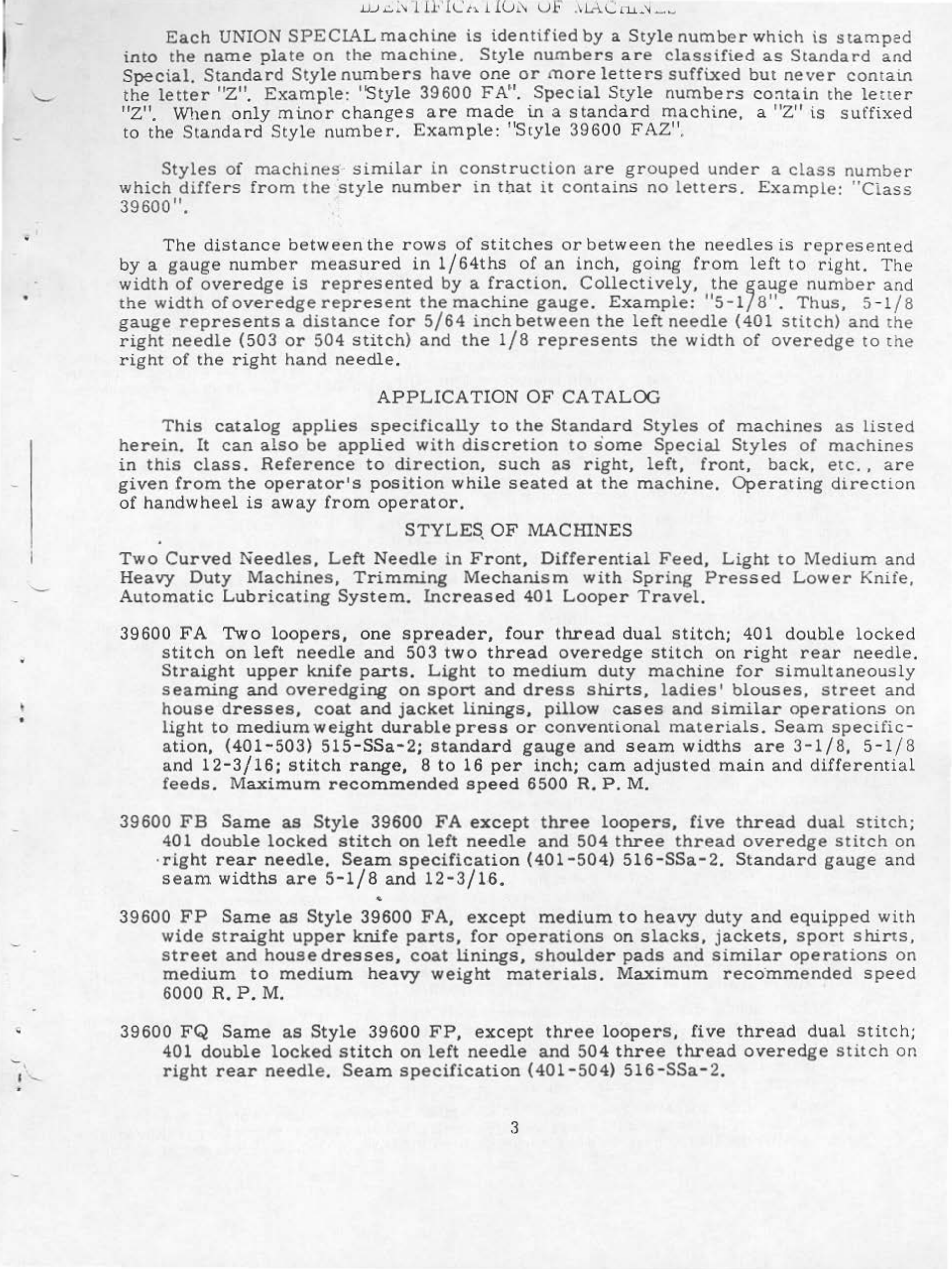
SETTiNG
ial
with
es
or
THE
feed
the
lowers
F
E.I:.:D
dogs
throat
DO<.."';S
(A,
pl
the bac
B.
ate
Fig.
surface
k
end
11).
by
of
rotatin
feed
g
bar.
feed
Feed
tilting
do
gs
sho
above
feed
feed
differential
inch
In
tighten
fa
throat
lateral
assembly
uld
replacing
ce
be l
the
tilting
dogs
above
SETT
Replace
screw
of
the
plate
motion
evel
throat
adjustin
at
highest
feed
the
ING
the
the
flange
mount
is
obtained
at
the time
pl
dog
throat
THE
lower
lower
(E
, F
on
of
the
ate
.
Screw
g
pin
p
oint
teeth
plate
LOWE
knife
knife
ig. 11)
sleeve
ing
when
bracket
lo
we r
teeth
in
plac
of
trav
should
.
R
holder
hold
so that
(F) sea
knif
the
knife
first
(
0) locks
e.
el.
KNIFE
er
(G). a
e
:--.low
."\!ain and
be
se
asse
assembly.
w
ts a
and
is
a
ppeac
the
se
t :3/
mb
he
n
the
gains
fr
ho
lde
manual
54.
ly
ee
r
t
.
t
-
-
•
Lower
tight
Set
righ
holder
ening
th
t
e
desired
edge
shaft
Fig.
knife
screw
of
lower
with
SETTING
may
(K)
width
screw
11
be
agai
of
knife
(K).
THE
secured
nst
trim
to
needle.
UPPER
the
by
ly
pressed
(H)
throat
with
lower
against
•ment
changed.
in
any
knife
measuring
L
KNIFE
holder
ock
should
plate
hexagonal
knife.
is
position
from
lower
be
the
neces
sha
knife
at
its
set
surface.
head
Lower
uppeP.
sary
by
ft.
the
upper
with
Adjustments
screw
knife
knife,
when
cor
cutting
ne
(J)
is
so
no
the width
r .
Low
ed
ge
which
spring
la
teral
er
flu
a
re
holds
of trim
k
nife
s h •Nith
made
pressed
a
djust-
the
is
-
I
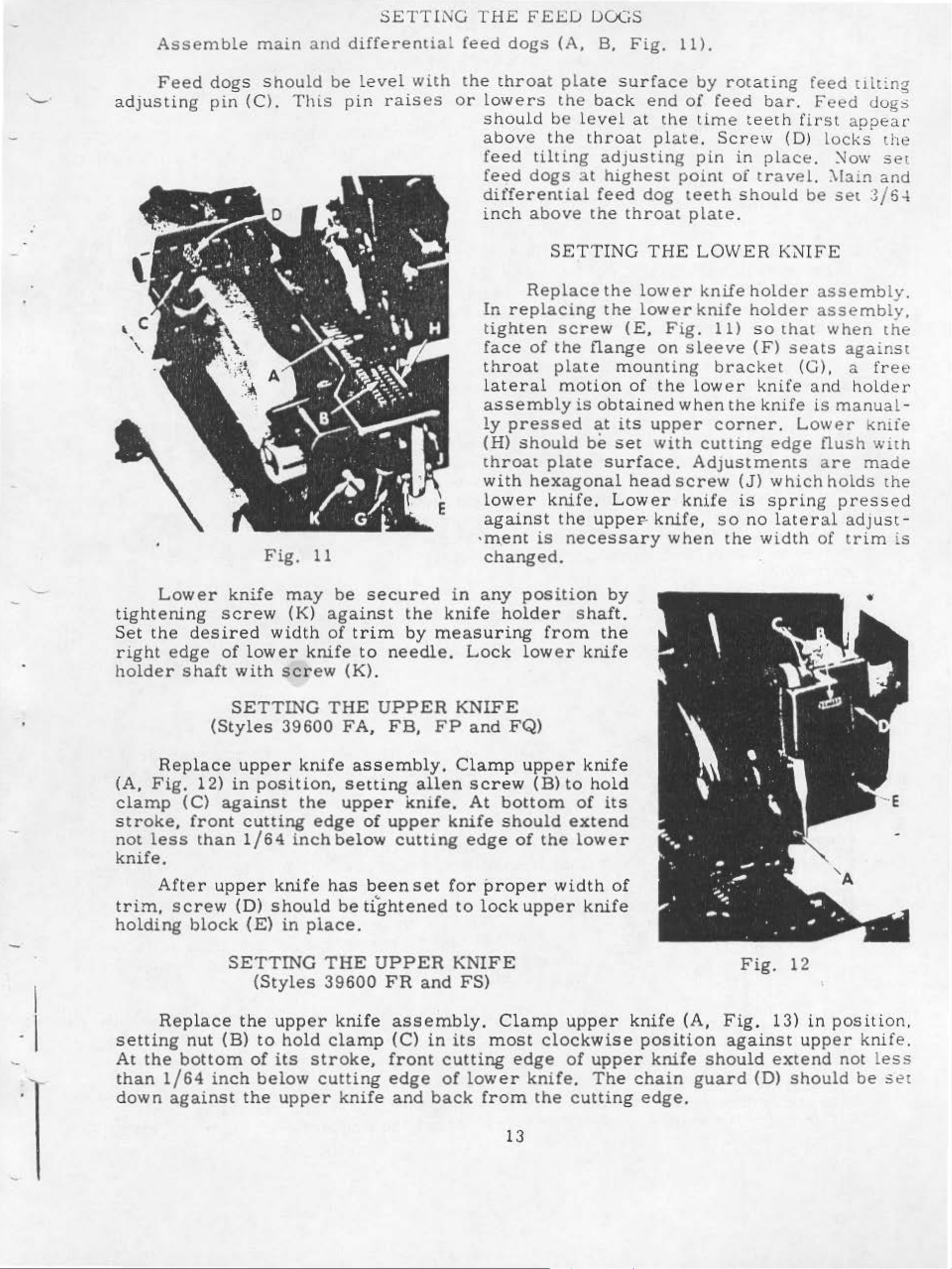
Replace
(A,
clamp
stroke,
not
knife.
trim,
holding
Fig.
less
After
scre
Replace
(Styles
upper
12)
(C)
front
than 1/64
block
in
against
cutting
upper
w (D)
(E)
SETTING
the
39600
knife
position,
the
edge
inch
knif
should
(Styles
upp
in
e
place.
er
FA,
assembly.
setting
upper
of
belo
has
be
THE
39600
knife
w
been
~
tightened
UPPER
FB,
knife.
upper
cutting
FR
assembly.
FP
allen
set
and
knife
for
KNIF
and
Clamp
screw
At
ed
to
FS)
bottom
should
ge
proper
lock
E
Clamp
FQ)
upper
(B)
of
upper
to
ex
the
width
upper
knife
hold
of
it
tend
lowe
knife
s
r
of
knife
(A,
F
ig.
F
ig. 13)
12
in
position.
'·
•
I
settin
At
t
han
down
g
the
1/64
against
nut
bottom
(B)
inch
to hold
of
its
below
the
upper
clamp
strok
cutting
knife
e,
(C)
front
edge
and
-
in
its
cutting
of
lower
back
most
edge
from
13
clockw
knife
the
ise
of
upp
.
Th
cutting
position
er
knife
e
chain
edge
should
guard
.
against
extend
(D)
upper knif
not less
should
be set
e.
..
After
tightened
when
upper knife
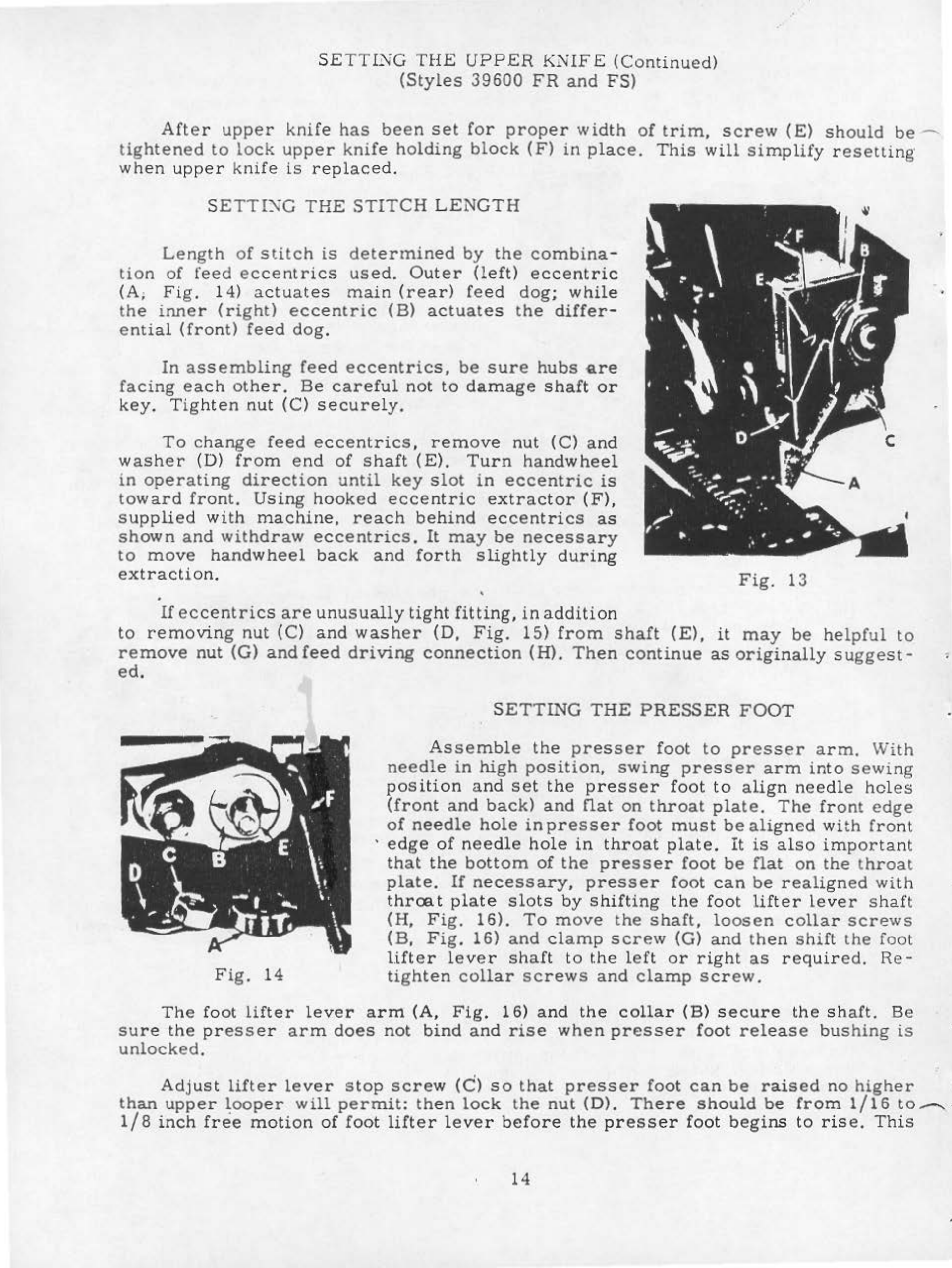
Length
tion
(A;
the
ential
of
Fig.
inner
(front)
upper
to
lock
SETTIXG
of
stitch
feed
14)
ec
centrics
actuates
(right)
feed
SETTING
knife
upper
is
has
knife
replaced.
THE
is
main
eccentric
dog.
(Styles
been
holding
STITCH
determin
used.
Outer
(rear)
(B)
T
HE
UPPER
39600
set
for
block
LENGTH
ed
by
feed
actuates
proper
the
(left)
KNIFE
FR
and
width
(F)
in
place.
combinaeccentri
dog; while
the
differ-
(Continued)
FS)
of
trim,
This
c
screw
will
(E)
simplify
should
resetting
be
-...
•
In
as
facing
key
.
washer
in
operating
toward
Tig
To
each
hte
change
(D)
front.
supplied
shown
to
move
and
extraction.
If
eccentrics
to
removing
remove
nut
sembling
other.
n
nut
(C)
feed
from
direction
Using
with
machine,
withdraw
handwheel
are
nut
(G)
(C)
andfeed
feed
Be
eccentrics,
careful
securely.
eccentrics,
end
of
until
hooked
reach
eccentrics.
back
unusually
and
wa
driving
not
shaft
key
eccentric
and
tight
sh
er
be
sure
to
damage
remove
(E).
slot
Turn
in
extractor
behind
It
may
fo
rth
eccentrics
be
slightly
'
fitting, in
(D,
Fig.
connection
hubs
shaft
nut
(C)
handwheel
eccentric
necessary
during
addition
15)
from
(H).
Then
Qre
or
and
is
(F)
as
,
shaft
continue
(E),
Fig.
it
may
as
originally
13
be
helpful
su
gge
to
st-
ed.
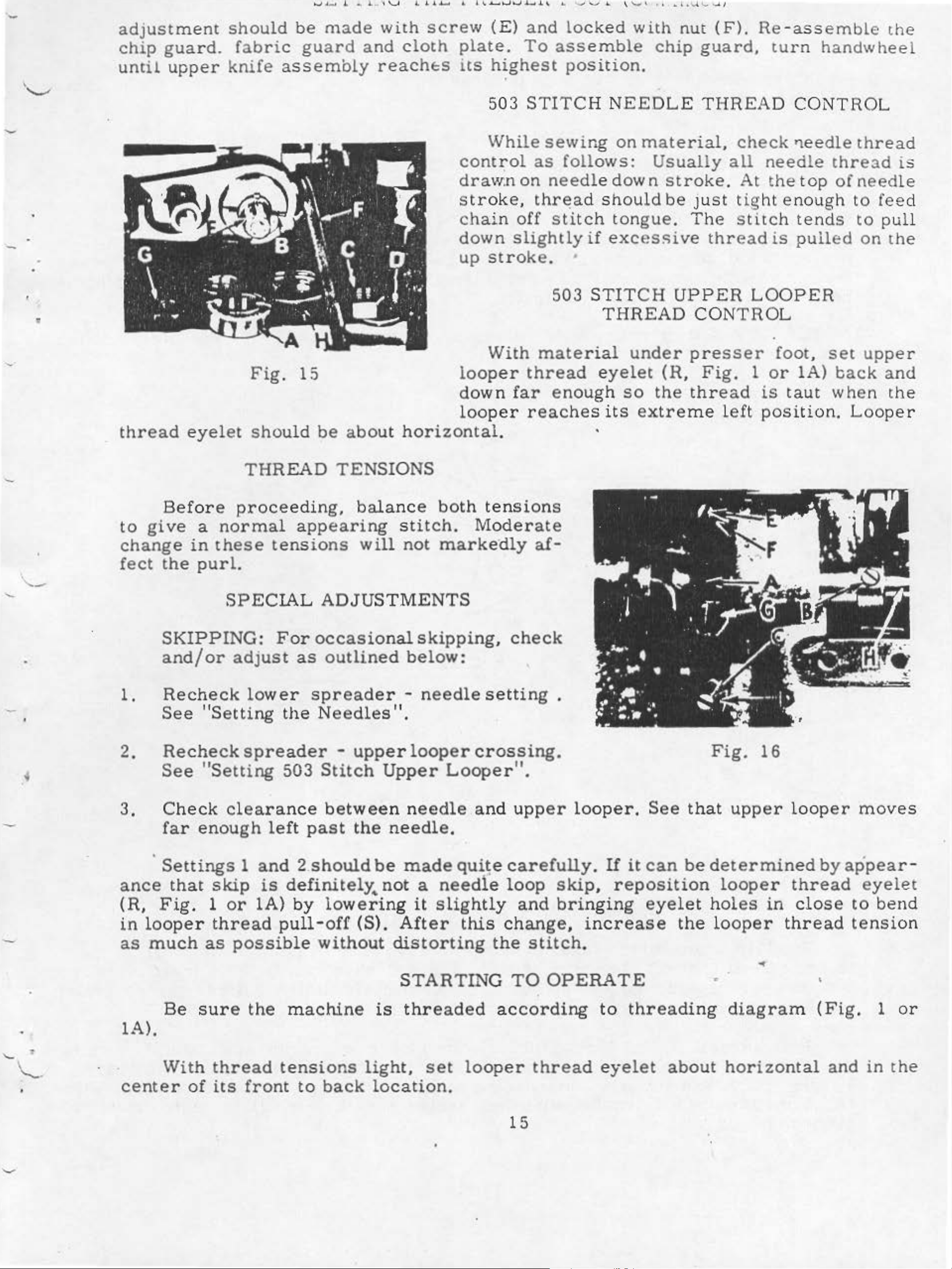
Fig.
14
Assemble
needle
position
(front
of
needle
'
edge
that
the
plate.
throo.t
(H,
(B,
lift
Fig.
Fig.
er l
tighten
in
and
of
needle
bottom
If
plate
ever
collar
SETTING
the
high
and
back)
hole
position,
set
th
and
in
presser
ho
le
of
necessary,
slots
16).
16)
To
and
clamp
shaft
screws
THE
presser
e
presser
nat
in
the
presser
presser
by shif
move
to
the
and
PRESSER
swing
on
throat
foot
throat
ting
the
shaft,
screw
left
clamp
foot
presser
fo
ot
must
plate.
foot
foot
the
(G)
or
FOOT
to
presser
to
align
plate.
be
It
be
can
foot
loosen
and
right
screw.
arm
needle
The
aligned
is
also
nat
be
on
realigned
lifter
collar
the
n
shift
as
requ
arm.
in
to
With
sewing
holes
front
with
edge
front
important
le
the
ve
throat
r s
screws
the
ir
ed.
with
ha
ft
foot
Re-
sure
The
the
foot
lifter
presser
lever
arm
a
does
rm
not
unlocked.
Adjust
than
1/8
upper
inch
lifter
~ooper
free
motion
lever
will
of
stop
screw
permit:
foot lifter lever
(A,
bind
th
en
Fig.
and
(C)
lock
16)
rise
so
that
the
before
14
and
when
presser
nut
the
(D).
the
collar
presser
foot
There
pr
ess
er
(B)
secure
foot
can
should
foot
release
be
raised
be
begins
the
sh
bushing
no
from
to
rise.
aft.
Be
higher
1/16
This
is
to.-...~
-
adjustment
should
be
made
with
screw
(E)
and
locked
with
nut
(F).
Re-assemble
the
-
•
chip
until
guard.
upper
fa
bric
knife
guard
assembly
and
cloth
reaches
plate.
its
contz:ol
draw:non
str
chain
down
up
h~ghest
503
While
oke,
stroke.
To
STITCH
off
slightly
assemble
position.
NEEDLE
sewing
as
follows:
needle down
thr~a
stitc
503
d
•
on
should
h
ton
if
excessive
STITCH
THREAD
chip
material,
Usually
stroke.
be
gue.
guard,
THREAD
just
The
thread
UPPER
CONTROL
turn
check
all
needle
At
the
tight
stitch
is
LOOPER
handwhee
CONTROL
11eedle
top
enough
tends
pulled
thread
thre
ofneedle
to
to
on
ad
fee
pull
the
l
is
d
thread
Before
to
give
change
fect
the
SKIPPING:
eyelet
a
normal
in
these
purl.
SPECIAL
Fig.
shou
THREAD
proceeding.
15
ld
be
appearing
tensions
ADJUSTMENTS
For
occasional
about
TENSIONS
balance
will
horizontal.
stitch.
not
skipping,
With
looper
down
looper
both
Moderate
markedly
far
tensions
check
material
thread
enoug
reaches
af-
under
eyelet
h
so
its
·
extre
(R.
the
presser
Fig.
thread
me
left
foot,
1
or
1A)
is
taut
position.
set
when
upper
back
Looper
and
the
•
1.
2.
3.
·
ance
(R,
in
looper
as
much
and/or
Recheck
See
Recheck
See
Check
far
Settings
that
Fig.
"Setting
"Setting
enough
skip
1
thread
as
adjust
lower
spreader
clearance
1
and 2.should
is
or
1A)
possible
as
the
503
left
definitely._
by
pull-off
outlined
spreader
Needles".
-
upper
Stitch
between
past
without
the
lowering
(S).
below:
-
needle
looper
Upper
needle
needle.
be
made
not
a
it
After
distorting
setting
crossing.
Looper"
and
qui~e
needle
slightly
this
carefully.
loop
change,
the
.
.
upper
skip
and
bringing
stitch.
looper.
If
it
,
reposition
increase
See
can
eyelet
that
be
the
Fig.
upper
determined
looper
hol
looper
es
16
in
thread
looper
thread
close
by
appear-
moves
eyelet
to
bend
tension
'-
.
\._,_
Be
1A).
With
center
sure
of
the
thread
its
front
machine
tensions
to
back
STARTING
is
threaded
light,
location.
set
TO
according
looper
15
OPERATE
to
thread
eyelet
threading
about
..
•
diagram
horizontal
(Fig.
and
1
in
or
the
STARTING
TO
OPERATE
(Continued)
Operate
and
as
Lower
Fig.
cam
eyelet
and
certtered
NOTE:
that
moves
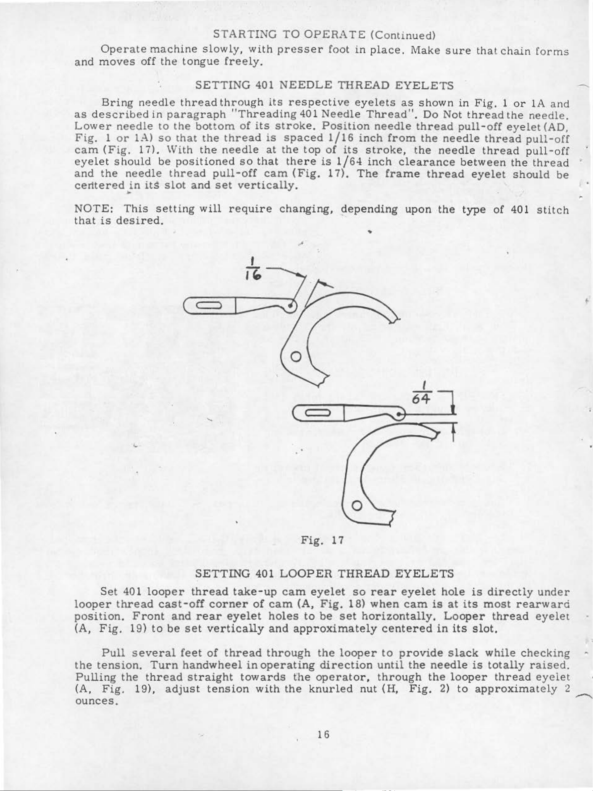
Bring
described
needle
1
or
(Fig.
shou
the
is
desired.
machine
off
needle
in
L-\)
17).
ld
needle
in
itg
•
This
the
to
so
be
setting
tongue
thread
paragraph
the
that
With
pos
thread
slot
and
slowly,
freely.
SETTING
through
"Th
bottom
the
the
ition
pull-off
set
will
of
thread
needle
ed
so
vertically
require
with
401
its
readin
its
is
at
that
cam
presser
NEEDLE
respective
g 401
stroke.
spaced
the
changing,
top
there
(Fig.
.
foot
Needle
Position
1/16
of
is
17).
in
THREAD
eyel
inch
its
1/64
The
depending
plac
Thread".
needle
stroke,
inch
e .
EYELETS
ets
as
from
clearance
frame
upon ·the
..
Make sure
shown
Do
thread
the
the
needle
thread
in
Not
pull-off
needle
betw
type
th
at
Fig.
thread
thread
thread
een
eyelet
of
chain forms
1
or
lA
and
the
eyelet
401
needle.
pull-off
pull-off
the
should
thread
stitch
(AD,
be
---.
( )
'·
(<
I
)
--'!)
64
J
Set
looper
position.
(A,
the
Pulling
(A,
ounces.
tension.
thread
Fig.
Pull
Fig.
401
Front
19)
several
the
thread
19),
loop
to
Turn
er
cast-off
and
be
adjust
SETTING
thread
corner
rear
set
feet
handwheel
straight
vertically
of
tension
eyelet
thread
•
401
take-up
of
cam
holes
and
through
in
operating
towards
with
Fig.
LOOPER
cam
the
eyelet
(A,
to
approximately
the
knurled
17
THREAD
Fig.
be
the
direction
operator,
so
rear
18)
set
looper
when
horizontally.
nut
EYELETS
eyelet
cam
centered
to
provide
until
through
(H,
the
Fig.
hole
is
at
Looper
in
its
slack
needle
the
looper
2)
to
is
directly
its
most
thread
slot.
while
is
totally
thread
approximately
rearward
checking
under
eyelet
raised.
eyeiet
2
....--....
16
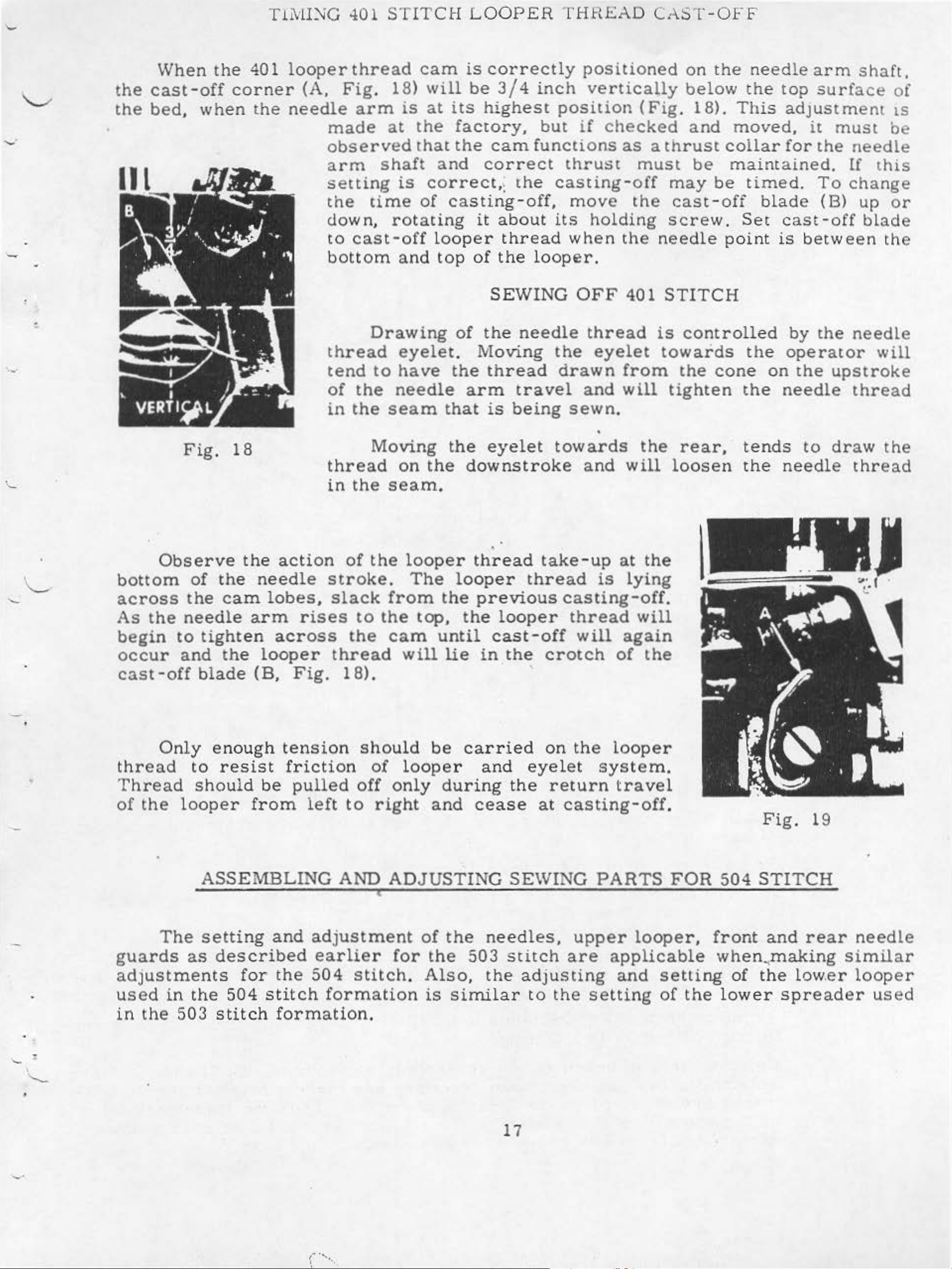
Tli\fl);G
401
STITCH
L
OOPER
THHI:::AD
CAST-OFF
When
the
the
:
cast
bed
,
the
-off
when
401
corner
the
looper
(A,
needle
made
observed
arm
setting
the
down,
to
bottom
thread
thread
Fig.
18)
arm
at
shaft
time
rotating
cast-off
Drawing
cam
will
is
at
the
that
is
correct
of
and
eyele
is
correctly
be
3/4
its
highest
factory,
the
and
cam
correct
,:
casting-off,
it
about
looper
top
of
thread
the
SEWING
of
the
t.
Moving
inch
position
but
functi
th
e
casting-off
its
loop
needle
the
positioned
verticaUy
if
checked
ons
as a thrust
thrust
move
the
holding
wh
en
the needle
er.
OFF
401
thread
eyelet
(Fig.
must
may
cast-off
scre
STITCH
is
towards
on
the
below
18).
and
need
the
This
moved,
coilar
be
maintained.
be
timed.
blade
w.
Set
point
controlled
the
le
top
arm
surface
shaft,
adjustment
it
must
for
cas
is
t -
betwe
by
the
To
(B)
off
the
needle
[f
change
up
en
needle
operator
of
ts
be
this
or
blade
th e
will
Observe
bottom
across
As
beg
occu
the
in
r
Fig.
of
the
the
cam
needle
to
tight
and
18
the
en
the
action
needle
lobes,
arm
acr
looper
tend
of
in
thr
in
stroke
slack
rises
oss
thread
to
the
the
Moving
ea
d
the
of
the
to
the
the
have
needle
seam
on
the
seam.
looper
.
The
from
top,
ca
m
will
the thread
arm
that
the
is
eyelet
downstroke
•
thread
looper
the
until
lie
previous
th
e l
ooper
cast-off
in
the
travel
being
toward
take-up
thread
crotch
drawn
and
from
will
sewn.
s
the
and
is
will
at
the
lying
casting-off.
thread
will
will
again
of
the
the
cone
tighten
rear,
loosen
on
th
e
needle
tends
the
needle
the
to
upstroke
thread
draw
the
thread
-
cast-off
Only
thr
ead
Threa
of
the
d
The
guards
blade
enough
to
resist
shoul
looper
(B,
d
be
from
tension
ASSEMBLING
setting
as
described
and
Fig.
18).
friction
pulled
left
to
AND
adjustment
earlie
should
of
off
looper
only
right
ADJUSTIN
r
for
be
during
and
of
the
the
carried
and
the
cease
G
SEWING
need
503
stitch
on
the
eyelet
return
at
casting-off.
les,
upper
are
looper
system.
travel
PARTS
looper
applicable
FOR
,
504
fro
Fig.
STITCH
nt
and
19
rear
when,making
needle
similar
adjust
u
se
in
the
•
d
in
ments
the
503
stitch
for
504
the
stitch
504
form
formation
/"'
I '
•,
stitch
atio
.
. Also,
n
is
simi
the
lar
17
ad
justing
to
the
and
setting
setting
of
the
of
the
lower
low.er
spreader
looper
used
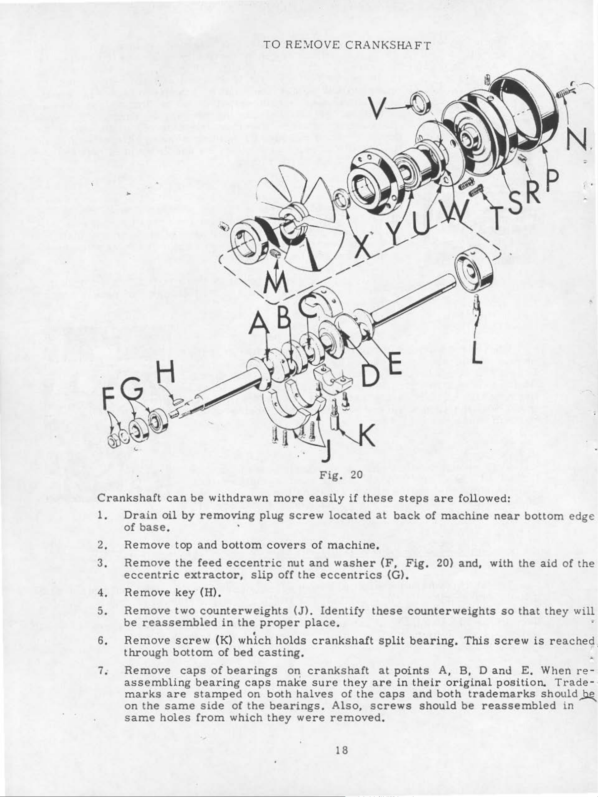
TO
R£~;[QVE
CRANKSHAFT
N.
•
I •
l
Crankshaft
1.
2.
3.
4.
5.
6.
Drain
of
base.
Remove
Remove
eccentric
Remove
Remove
be
reassembled
Remove
through
can
oil
by
top
the
extractor,
key
two
screw
bottom
be
withdrawn
removing
and
feed
(H).
counterweights
bottom
eccentric
in
the
plug
slip
proper
•
(K)
of
which
bed
casting
more
screw
covers
nut
off
holds
the
(J).
Fig.
easily
located
of
machine.
and
eccentrics
Identify
place.
crankshaft
. _
20
if
these
washer
at
back
(F,
(G).
these
split
steps
Fig.
counterweights
bearing.
are
of
machine
20)
followed:
and,
This
near
with
so
screw
bottom edge
the
that
aid
the
is
reached.
of
y w
the
ill
=
7.
Remove
assembling
marks
on
the
same
holes
caps
are
same
of
bearings
bearing
stamped
side
from
of
which
caps
on
the
on
make
both
bearings.
they
crankshaft
•
halves
were
sure
Also,
removed.
18
they
of
the
at
points
are
screws
in
caps
A,
their
and
both
should
B,
original
D
trademarks
be
reassembled
and
position.
E.
When
Trade-·
should~
re-
in
-
E
D
•
B
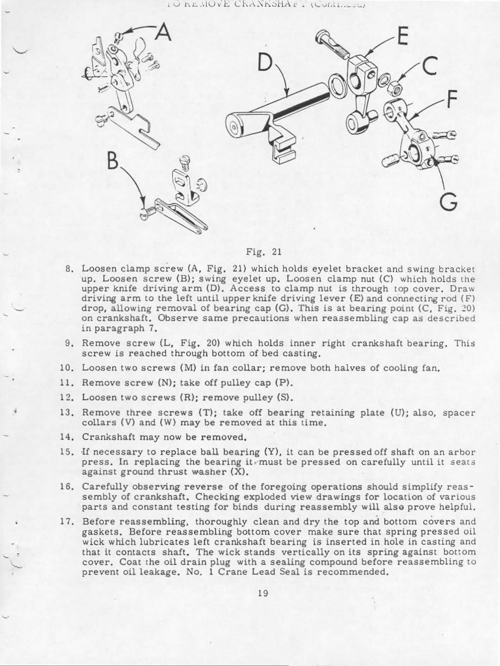
8.
9.
Loos
up.
upper
driving
drop, allowing
on
in
Remove
screw
en
clamp
Loosen
knife
arm
crankshaft.
paragraph
screw
is
reache
screw
driving
to
screw
the
removal
Observe
7.
(L,
d
throu
(A,
(B);
arm
left
Fig
Fig
swing
(D).
until
of
bearing
same
. 20)
gh
bottom
Fig
.
21) which
eyelet
Acces
upper
precautions
which
.
s
knife
cap
holds
of
bed
21
up.
to
driving
(G).
•
holds
Loosen
clamp
when
inner
casting.
eyelet
This
bracket
clamp
nut
lever
reassembli
right
is
is
through
(E)
at
bearing
crankshaft ·bearing
nut
and
and
(C)
connecting
point
ng
swing
which
top
cap
cover.
as
(C,
de
G
brac
holds
Dr
rod
Fig.
scr
. T
ket
the
aw
(F)
20)
ibe
his
d
-
•
•
10.
11.
12
.
13.
14.
15.
16.
17.
Loo
sen
Remove
Loosen
Remove
coll
Cran
·
If
press.
against
Carefully
sembly
parts
Before
ars
kshaft
nece
ssary
In
and
reassemb
two
screw
two
(V)
ground
of
screws
screws
three
and
may
to
replacing
obser
crank
consta
(M)
(N);
scr
(W)
now
replace
thrust
ving
shaft.
nt
take
(R);
ew
may
be
the
reverse
testing
ling,
in
fan
off
pul.ley
remove
s
(T);
be
take
remove
removed.
ball
bearing
w-asher
Checking
thoroughly
bear
for
colla
pulley
off
ing
it.•must
(X).
of
the
exploded
binds
r;
rem
cap
d
clean
(P)
(S).
bearing
at
this
(Y),
foregoing
dur
it
be
ing
and
ove
.
view
both
retaining
time.
can
pressed
reassembly
be
operations
drawings
dry
the
halves
plate
pressed
on
carefully
will
top
and
of
cooling
(U);
off
should
for
shaft
simplify
location
also
prove
. '
bottom
fan.
also,
on
until
of
covers
spacer
an
arbor
it
seats
reas-
various
helpful.
and
gaskets.
'-
.
wick
that
which
it
cover.
'
'----
prevent
Before
lubricates
contacts
Coat
oil
the
leakage.
reassembli
left
shaft.
oil
The
drain
No
. 1
crankshaft
plug
ng
bottom
wick
with
Crane
stands
a
Lead
19
cover
bearin
vertically
sealing
Seal
make
g
is
inserted
on
compound
is
recommended.
sure that
in hole
its
spring
before
spring
against
reassembling
pressed
in
casting
oil
and
bottom
to
\
\
'
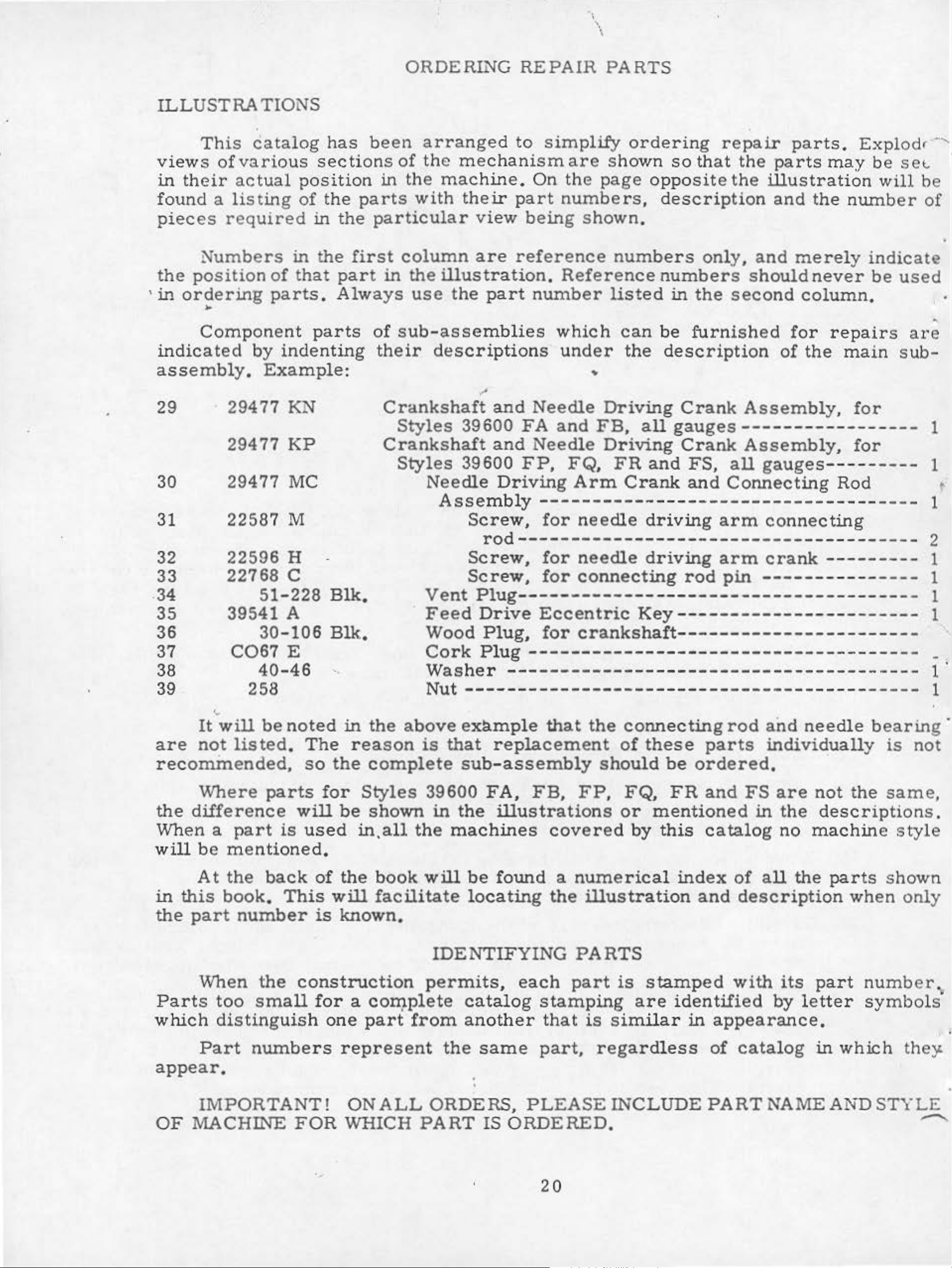
ILLUSTRATIONS
views
in
their
found
pieces
the
'
in
ordering
This
of
a
N
umbers
position
catalog
various
actual
listing
re
quired
of
parts.
in t
that
..
Component
indicated
by
indenting
has
sections
position
of
the
in
he
parts
the
first
part
Always
parts
ORDERING
been
in
arrange
of
the
the
machine
with
particular
column
in
the
illustration
use
of
sub-assem
their
descrip
REPAIR
d
to
mechanism
.
On
their
v
are
the
part
part
iew
being shown.
reference
number
blies
tions
PARTS
simplify
are
the
shown so
page
numbers,
. Re
ference
listed
which
under
ordering
opposite
descri
numbers
numbers
in
can
the
be
description
repair
that
the
the
illustration
ption
onl
y,
and
should
the
second
furnished
parts.
parts
and
merely
column
for
of
the
may
the
number
never
repairs
main
Explodr
be
se
t.
will
be
of
indica
be
te
use
•
are
sub-
-,
d
'
assembly.
29
30
31
32
33
22596
22768 c
.34
35
36
37
Example:
29477 KN
29477
KP
29477 MC
22587
M
H
51-228
39541 A
30-106
C067
E
Blk,
Blk.
Crankshaft
Styles
39600
Crankshaft
Styles
39600
Needle
Assembly
Screw,
Screw,
Scr
Vent
Feed
Wood
Cork
..
••
•
and
and
Driving
Needle
FA
and
Needle
FP,
FB,
FQ,
Arm
Driving
all
Driving
FR
and
Crank
Crank
Assembly,
gauges-----------------
Crank
FS,
and
Assembly,
all
gauges
Connecting
----Rod
for
for
------------------------------------
for
needle
driving
arm
connec
ting
rod--------------------------------------
for
ew, for
Plug-------------------
Drive
Plug,
Plug-------------
Eccentric
for
needle
driving
connecting
Key
crankshaft
-------------
rod
---
arm
pin
---------
----------
crank
---
---------------
----------
----
----------------------
-----------
------
------
----
1
1
•
1
2
1
1
1
1
-
_
38
39
are
'•
It
will
not
40-46
258
be
listed.
recommended,
Where
the
difference
When a
will
be
At
in
this
the
part
part
mentioned.
the
book,
parts
back
number
noted
The
so
will
is
used
of
This
is
'
in
reason
the
for
Styles
be
in,all
the
will
known.
VVasher
Nut
the
complete
shown
above
is
39600
in
the
book
will
facilitate
IDENTIFYING
-----
-------------------------------------------
example
that
sub
the
machines
replacement
-as
sembly
FA,
illustrations
be
found
locating
--------
that
FB,
FP,
covered
a
numerical
the
--------------
the
illustration
connecting
of
these
should
be
FQ,
or
mentioned
by
this
FR
parts
ordered.
and
catalog
index
and
PARTS
-
-----
rod
and
needle
individually
FS
in
are
the
no
of
all
the
description
------
bearin
is
·
not
description
machine
the
parts
when
sam
shown
1
1
g ·
not
e,
s .
style
on
ly
When
Parts
which
Part
too
distinguish
the
small
construction
for
numbers
a COil).plete
one
part
represent
from
appear,
OF
IMPORTANT!
MACHINE
FOR
ONALL
WHICH
...
permits,
catalog
another
the
same
•
•
ORDERS,
PART
IS
each
part
stamping
that
part,
PLEA
is
regardless
SE
ORDERED.
20
is
stamped
are
similar
identified
in
with
its
by
letter
appearance.
of
catalog
part
in
which
number,
symbols
INCLUDEPARTNAMEANDST
th
e)'
YLE
............
•
v::.£
G£0.'
...:
IN
E N
EED
LES
AND
R.EPAirt
i'Af{TS
Success
UNION
p0ratio:1,
to
the
.
efficiency
::no.st
Genuine
p3.rts
is
your
are
SPECIAL
its
and
stamp-~d
guarantee
in
the
operation
Needles
subsidiaries
scientific
durability
needles
are
with
of
the
of
and
and
Repair
authorized
principles,
are
assured.
p3.ckaged
the
Union
highest
these
machines
Parts
as
furnished
distributors.
and
with
are
labels
made
mar
Sp.acial.trademark,
quality
in
materia
can
with
ked
ls
TERMS
- .
Prices
are
forwarded
otherwise
are
strictly
f.
o.
directed.
b.
A
net
cash
shipping
charge
point.
is
and
subject
made
Parcel
to
cover
to
change
Post
postage
be
secured
by
They
the
are
utinost
U S
and
Emblem.
workmanship.
without
shipments
and
insura
only
Union
designed
precision.
.
Genuine
Each
notice.
are
All
insured
nce.
with
genuine
Special
according
Maximum
trademark
shipments
unless
Cor-
rep3.ir
.
·.....__,.
Torque
a
distance
driver,
amount
of
All
otherwise
as
ti~htly
The
(measured
by
etc.
torque
straps
noted.
as
possible,
screws
a
lever
Many
will
and
All
requiring
in
inch-pounds)
(in
of
inches
these
tighten
eccentrics
other
unless
a
TORQUE
or
feet),
devices
the
part
should
nuts,
bolts,
otherwise
specific
REQUIREMENTS
is a rQtating
This
are
to
available.
the
be
correct
tightened
screws,
noted
•
torque,
•
will
is
force
accomplished
amount
etc.,
be
indicated
(in
which
to
19-21
should
pounds)
by
when
and
inch-pounds,
be
on
applied
a
wrench,
set
no
at
tighter.
tig:htened
the
··
picture
the
through
screw
proper
unless
by
han
plates
d
•
'
~
·
-
>
·.'-....-
,
21
STYLES
OF
:v!ACHI~ES
(Continued)
39600
FR
for
similar
speed
39600
FS
locked
Seam
Class
speeds.
operating
than
recommended
These
mum
speed
c
ha
performance,
for
nisms.
Same
as
operations
operations
6000 R. P .
Same
stit
as
ch
specification
39600
Varied
machines
field
at a lower
machines
the
first
Style
on
39600
slacks,
on
M.
Style
on
left
39600
(401-504)
conditions,
speed
stitch
are
the
20
days
length,
precision
machine
FA.
Jackets,
medium
FR.
needle
have
been
severity
. When
should
of
field
except
sport
to
medium
except
a nd 504
516-SSa-2.
SPEED
RECOMMENDATION
tested
and
operating
it
may
be
manufactured
be
operated
operation.
medium
shirts,
to
jacket and
heavyweight
three
loopers,
three thread
in
their
complete
cleanliness
from
necessary
This
50-100%
to
and
at
tested
1000 ,R.
will
·
heavyduty
materials.
five
over
edge
stitch
of
the
sewing
machine
reduce
sewing
P.M.
minimize
and
angular
coat linings,
Maximum
thread
stitch
range
dual
on
at
operation
running
the
machine's
machines.
below
maximum
readjustment
upper
shoulder
recommended
stitch;
right rear
their
maximum
may
cycle
speed
To
recommended
of
precis
knife
401
parts.
pads
double
and
needle.
rated
necessitate
and a longet·
by
10-15.-
obtain
ion
maxi-
o.
me-
~
•
•
CAUTION! Oil
beginning
Saybolt
viscostty
Machine
front
of
machine.
stationary
Machine
voir
ting
in
filled.
To
maintain
continuously,
machine
The
magnetic
cr
ank
case
to
operate.
.
Check
for
oil
drain
screw
..
It
was
Oil
of
90
is
filled
Red
is
automatically
oil
with
bulb
daily
maximum
the
more
plug
oil
than
screw
designed
should
be
drained
capacity
to
125
oil
on
before
recommended
must
one
to
accumulate
removed
from
seconds
at
spring
oil
level
machine
of
Class
at
indicator
lubricated.
the
be
changed
morning
year.
is
located
and
cleaned
OILING
39600
1000
cap
No
in
oiling
speed
at
least
at
the
possible
when
shipped, so
is
seven
Fahrenheit
top
back
cover.
should
is
start;
and
serviceability
every
of
show
necessary,
add
six
machine
foreign
periodically.
reservoir
ounces.
should
Oil
be
level
between
other
oil
as
required.
months.
near
materials
A
straight
used
is
.
checked
gauge
than
of this
In
equipmen
no
bottom
which may
must
at
lines
keeping
case
should
edge
be
filled
mineral
sight
when
machine
main reser-
t when
oil
of
base.
have
entered
before
otl
of
gauge
opera-
rema1n
It
on
is
the
a
is
•
a
•
Each
kind
of
shank,
the :1eedle
way
which
the
curved
and
between
is
given
Two
needles
overedge
blade,
is
available
110/0H.
The
round
needle
To
or
the
would
lo:1ger
p"Jint,
and
have
typoe
read:
UNION
p"Jint,
shank,
shank
on
stitch,
standard
125/049,
needle
curved
is
available
needle
and
size
"1000
SPECIAL
length,
denotes
and
the
havi
eye,
label
ng
different
located
length,
in
sizes
140/054,
for
blade,
in
sizes
orders
number
Needles,
needle
groove,
largest
diameter
Collectively,
of
all.needles
lengths
at
the
single
055/022,
150/060.
the
401
Class
stitch,
C,
070/027,
promptly
should
Typo?
154
has
both
finish
p.1Ckaged
are
right,
goove,
065/025,
located
double
075/029,080/032,
and
be
accurately
forwarded.
GAS,
NEEDLES
a
typo?
and
of
typ~
other
blade,
and
used
is
Type
struck
070/027, 075/029, 080/032,
at
groove.
Size
080/032".
and
details.
measured
siz
e
and
in
154
sold
these
GAS.
groove,
the
left,
struck
filled,
Use
description
size number
The
in
number
by
represent
Union
machines.
It
is
sp"Jtted.
is
Typo! 161 GS.
gro::>ve,
090/036,
an
empty
.
The
size
type
number,
thousandths
the
Special.
a
round
The
shorter
shank,
chromium
090/036,
It
spotted,
100/0.tO,
package,
on
label,
number
stamped
of
an
inch,
complete
needle
round
plated
is a round
chromium
110/044,
a
sample
A
complete
denotes
on
mid-
symbol
for
point,
needle
100/040.
shank.
p!ated
125/049.
needle.
order
Selection
freely
through
Success
p.
ackaged
highest
under'
quality
of
proper
needle
in
the op<!ration
our
needles
eye
brand
in
needle
in
size
order
of
name,
materials
to
UNION
~.
and
is
determined
produce
SPECIAL
workmanship
by
a
good
machines
which
4
size
s t
and
of
itch
is
backed
for
thread
formatio:'l,
can
be
secured
by
more
than
used.
Thread
only
a
rep:ltation
three-quarter
should
by
use
of
forproducing
of
pass
needles
centurj
.
 Loading...