


INDUSTRIAL
SEWING
FINEST
STYLES
39500QA
39500QB
39500QP
39500QY
39500RA
39500RF
39500RM
39500RR
39500RS
QUALITY
®
C O L U M B I
A®
MACHINES
39500SE
39500SF
39500SG
39500TA
39500TD
39500TH
CATALOG
No.
103QA
MARK
SINGLE
TWO
CLASS
IV
OR
THREE
395
00
HIGH
NEEDLE
DIFFERENTIAL
OVERSEAMING
MACHINES
SPEED
THREAD
FEED
UNION SPECIAL
CHICAGO
CORPORATION

Catalog
No.
INSTRUCTIONS
FOR
103
QA
39500
39
39500
ADJUSTING
QA
500
QB
QP
39500
39500
QY
RA
LIST
CLASS
First
AND
OF
Styles
39500
39500
39500
39500
39500
OPERATING
PARTS
39
5 O O
RF
RM
RR
RS
SE
Edition
39500
39500
39500
39500
39500
TH
SF
SG
TA
TD
Rights
UN
ION
Union
Reserved
SPECIAL CORPORATION
INDUSTRIAL
Printed
Copyright©
By
Special
SEWING
CHICAGO
in
2
1973
Corporation
in
All
Countries
MACHINES
U.S.A.
April,
1980
IDENTIFICATION
OF
MACHINES
Each
on
the
machine.
Style
Example:
only
standard
which
39500
herein.
Class
given
of
MARK
Thread
Trimming
System,
numbers
minor
Styles
differs
".
This
39500.
from
handwheel
IV
UNION
"Style
changes
Style
of
machines
from
catalog
It
can
References
the
is
Hi-Styled
or
One
Mechanism
Improved
SPECIAL
Style
have
39500
number.
applies
also
operator's
away
Looper -One
one
the
be
High
Air
numbers
or
QA".
are
similar
Style
applied
to
from
Speed,
with
Cooling
machine
more
Spec:ial
made
Example:
number
APPLICATION
specifically
with
directions.
position
operator.
STYLES
Spreader
Spring
System.
is
are
classified
letters
Style
in a standard
"Style
in
construction
in
discretion
while
Single
Pressed
identified
suffixed,
numbers
39500
that
it
OF
to
the
Standard
to
such
OF
Curved
-
as
seated
MACHINES
Two
Lower
by a Style
as
standard
but
machine.
QAZ
are
grouped
contains
CAT
ALOO
some
right,
at
the
Blade
Thread
never
contain
a
".
no
letters.
Styles
Special
left,
machine.
Needle,
Machine,
Knife,
number
and
contain
the
"Z"
under a Class
of
Styles
front,
Automatic
on a name
special.
the
letter
is
suffixed
Example:
machines
of
back,
Operating
Two
Looper -Three
Differential
plate
Standard
letter
"Z
machines
Lubricating
"Z
".
When
to
the
number
"Class
as
listed
etc.,
direction
are
Feed,
".
in
39500
39500
39500
*
39500
QA
Light
warp,
The
children's
hanging
seam
cam
R.P.M.
QB
warp,
The
shirts,
garments.
1/8
and
QP
warp,
sweat
standard
adjusted
R.P.M.
QY
knit
knives.
mm);
Maximum
and
sewing
seams
widths.
adjusted
Light
and
sewing
polo
inch
differential
Medium
and
shirts,
Medium
outerwear
stitch
to
medium
ribbed
combination
slips,
are a primary
3/32and
main
to
medium
ribbed
combination
shirts.
Seam
(2.
38
and
feeds.
to
ribbed
underwear
seam
main
Seam
recommended
width,
and
to
made
Specification,
range.
duty
knit
fabrics
has
pajamas.
and
knit
panties,
Specification,
3.
17
heavy
knit
differential
heavy
8-20
nightgowns,
1/8inch
differential
duty
machine
fabrics
has
mm);
Maximum
duty
fabrics
and
1/8
inch
duty
from
per
speed
machine
of
cotton,
been
requisite.
been
machine
similar
machine
cotton,
504-SSa-1;
designed
(2.
38and
feeds.
of
cotton,
designed
infant
504-SSa-1;
stitch
recommended
made
inch;
(3.
feeds.
7500
from
17
cam
R.P.M.
for
seaming
silk,
especially
or
similar
Seam
3.17
Maximum
for
seaming
silk,
for
and
children's
range,
for
seaming
cotton
garments.
mm);
Maximum
for
seaming
wool
and
standard
adjusted
light
or
Specification,
mm);
light
or
general
standard
8-30
speed
and
Seam
stitch
synthetic
and
similar
for
articles
stitchrange,
recommended
and
similar
purpose
knit
seam
per
inch;
8000
medium
wool,
Specification,
range,
recommended
medium
seam
main
medium
weight
use
where
504-SSa-1;
medium
weight
wear,
widths,
cam
R.P.M.
to
heavy
used
8-20
and
yarns.
width,
and
differenti
weight
synthetics.
on
women's
long
8-30per
speed
weight
synthetics.
seaming
and
adjusted
weight
on
snow
504-SSa-1;
per
inch;
speed
heavy
Wide
1/8
inch
flat,
and
straight
standard
inch;
8000
flat,
of
"T"
similar
3/32
al
and
main
flat,
suits,
cam
7500
loosely
cutting
(3.17
feeds.
*
DISCONTINUED
-
In
repair.
most
instances,
component
3
parts
can
be
ordered
for
customer
STYLES
OF
MACIDNES
(Continued}
39500
39500
*
39500
39500
RA
Medium
wear
a
Wide
inch
feeds.
39500
ribbed
standard
stitch
recommended
elastic
power
5 / 8
(5.
3/32
ential
elastic
stitch
those
Seam
seam
main
made
reinforcing
cutting
(3.
97
Maximum
RF
Medium
QB
sewing
knit
seam
range. 8-20
RM
Light
to
panties,
driven
inch
( 7.
56
mm}
inch
(2.
feeds.
RR
Medium
to
girdles
·.
Machine
who
Specification
width
and
differential
mm};
wide
do
to
from
tape
knives.
stitch
to
cotton,
widths,
speed
to
medium
metering
94
to
leg
38
mm};
Maximum
to
can
not
1/4
inch
heavy
cotton.
recommended
heavy
parts.
half
15.
heavy
wish
used
Seam
wool,
per
7500
88
elastic.
stitch
and
be
503
(6.
feeds.
duty
wool
on
shoulder
Specification,
range,
duty
machine.
For
rayon
3/32,
inch;
R.P.M.
duty
slips
and
device
mm};
Seam
range,
recommended
duty
foundation
used
to
trim
or
505-SSa-l,
35
machine
and
synthetic
8-20
seaming
cam
machine
can
machine
with
mm};
Maximum
per
speed
and
silk
1/8
adjusted
similar
and
elastic
also
Specification
8-30
garments
or
the
stitch
for
seaming
seams
same
and
for
speed
for
without
material,
of
504-SSa-1;
inch;
7500
R.P.M.
as
all
types
fabrics.
5/32
main
seaming,
garments.
guide
be
ordered
per
break
hinged
range.
recommended
medium
yarns,
sweaters
cam
adjusted
Style
and
Seam
inch
and
differential
Prepared
roller.
503-SSa-1;
inch;cam
7500
with
the
R.P.M.
open
either a two
standard
a
front
open
8-30
and
with
provision
and
similar
standard
main
39500
(2.
trimming
to
QP.
weights
Specification,
38,
3.17
and
for
Elastic
handle
adjustedmainand
seaming
fabric
to
make
per
speed
narrow
standard
trimming
guide
inch;
7500
heavy
seam
except
of
feeds. Maximum
or
LSa-1;
knit
for
width.
and
differential
flat.
504-SSa-1;
and
attaching
use
with
width,
seam
and
attaching
three
knives.
is
cam
R.P.M.
outer-
inserting
garments.
5/32
fitted
3.
7 / 3 2
included.
with
warp
standard
and
97
mm};
frill
Galkin
5/16
inch
width,
differ-
thread
For
adjusted
to
of
39500
39500
39500
*
39500
*
DISCONTINUED
RS
Light
edge
requiring
seam
main
purpose
Jesse
width
differential
used
similar
knife
inch
differential
other
ard
main
SE
SF
SG
seams
and
Light
1/8
Medium
for
parts.
(3.17
Light
light
seam
and
to
medium
on
pajamas,
reinforced
width,
Heap
3/32
differential
to
medium
of
seaming
folder
inch
(3.17
feeds.
to
heavy
attaching a reinforcing
garments.
Seam
and
feeds.
to
to
width,
differential
-
Specification,
4.
76
medium
medium
1/8
In
most
repair.
duty
seams.
inch
(2.
feeds.
duty
and
attaching
No.
U-100.
mm};
Maximum
duty
tape
mm};
Maximum
duty
weight
inch
feeds.
instances,
machine
negligees,
Seam
38
mm};
Maximum
machine
stitch
recommended
machine
automatically
stitch
recommended
machine
material.
(3.17
Maximum
Specification,
collarettes
Seam
range,
tape
504-SSa-1;
range,
mm};
component
for
producing
peignoirs,
stitch
for
range,
recommended
with
reverse
Specification,
8-30
speed
for
seaming
used
stitch
on
guided
standard
8-20
upturned
Seam
recommended
per
speed 7 500
range,
parts
high
blouses
504-EFe-1
to
"T"
per
shoulder
by
slot
inch;
hem
Specification,
and
8-30
per
speed
differential
shirts.
504-SSa-1;
inch;
8000
can
bulky
in
seam
on
8-15
speed
be
cam
R.
seams
cam
R.
per
quality,
similar
inverted;
inch;
8000
Prepared
adjusted
P.
M.
knit
sweaters;
presser
widths
adjusted
P.
M.
cotton
505-EFa-1;
inch-
8000~R.
ordered
turned
sheer
cam
R.P.M.
feed
for
standard
of
sweaters
foot.
1/8
wash
cam
P.
for
down
items
standard
adjusted
general
to
accept
seam
main
can
Straifht
and 3 16
main
cloths
stand-
adjusted
M.
customer
and
be
and
and
and
4

STYLES
OF
MACHINES
(Continued)
39500
*
39500
*
39500
maximum
sewing
50-100%
may
TA
Light
Specification
2.
38
mm)
main
having a square
light
seams
widths.
cam
R.P.M.
flies
and
3/8
ential
39500
be
and
TD
Light
and
are a primar:y
adjusted
TH
Medium
and
similar
inch
feeds.
MARK
rated
operation
machine
necessary
duty
505-EFe-1
depending
differential
to
medium
3/3 2 and
main
zipper
operations.
(9.
52
Maximum
IV
speeds.
may
machine.
medium
separation
weight
1/ 8 inch
and
to
heavy
tapes
mm);
machines
necessitate
running
to
reduce
for
inverted;
on
material;
feeds.
requisite.
differential
to
stitch
SPEED
Varied
cycle
Maximum
duty
recommended
the
machine
located
perma-press
(2.
duty
machine
pants
Seam
range.
have
field
and a longer
machine's
toe
closing
standard
stitch
approximately
Seam
38
and
feeds.
fronts;
Specification
6-16
RECOMMENDATION
been
tested
conditions.
operating
on
women's
seam
range.
recommended
with
the
main
materials
Specification
3.
17
Maximum
for
simultaneously
also
per
speed
in
at a lower
than
speed
where
mm);
attaching
504-SSa-1;
inch;
7500
their
severity
recommended
by
10-15%.
width.
15-100
speed
and
at
504-SSa-1;
stitch
recommended
zippers
cam
R.P.M.
complete
speed.
seamless
1/16
to3/32
per
inch;
8000
differential
the
needle.
long
straight
range.
attaching
standard
adjusted
stitch
and
cleanliness
When
hosiery.
cam
R.P.M.
standard
8-30
to
right
main
range
operating
stitch
inch(l.
adjusted
feed
for
seaming
pucker
per
speed
right
flies
seam
and
at
length.
Seam
59
dogs
free
seam
inch;
8000
pants
only
width,
differ-
their
of
the
from
to
it
The
MARK
maximum
mum
readjustment
CAUTION!
filled
A
straight
should
Machine
sight
lines
Machine
main
To
when
no
case
The
It
is a magnetic
have enter ed
performance,
recommended
before
mineral
be
used.
gauge
when
reservoir
operating
machine
maintain
should
drain
IV
is a precision
of
precision
Oil
was
beginning
oil
is
filled
on
front
is
automatically
filled.
maximum
continuously,
oil
remain
plug scr
scr
the
crank case
manufactured
the
machine
speed
of
is
ew
for
the
first
mechanisms.
drained
to
of a Sayboltviscosity
with
machine.
stationary.
Check
recommended
in
ew
is
designed
from
operate.
oil
at
spring
Red
lubricated.
oil
daily
the
oil
machine
located
to
.
It
s
hould
accumulate possible
should
20
OILING
machine
Oil
tip
before the
must
for
at
days
cap
of
No
speed
more
back
be
be
capacity
of
oil
be
r e
mov
and
operated
of
field
when
90
to
in
top
indicator
oiling
morning
and
changed
than
of
machine
ed
tested
of
125
cover.
is
serviceability
one
and
sewing
at
1000
operation.
shipped,
Class
seconds
should
necessary,
start; add
at
least
year.
near
foreign
cleaned
39500
Oil
machine.
R.P.M.
This
so
reservoir
is
at
100°
level
show
other
oil
of
every
bottom
ma teria
peri
odicall
To
below
will
minimize
eight
Fahrenheit
is
checked
between
than
as
required.
this
equipment
six
months.
edge
ls
which
y.
obtain
maxi-
must
ounces.
gauge
keeping
of
base.
may
be
at
In
*
DISCONTINUED
-
In
repair.
most
instances,
component
5
parts
can
be
ordered
for
customer
NEEDLES
Each
denotes
number,
in
thousandths
size
packaged
the
stamped
number
and
Class
needle
154
154
154
for
GAS.
GBS;
GHS.
commended
Type
154
154
No.
GAS
GBS
UNION
kind
39500
Styles
For
while
Below
SPECIAL
of
shank,
on
of
an
represent
sold
by
machines
39500
Styles
for
Styles
are
the
inch,
the
Union
39500
the
needles.
Round
struck
055/022,
shank,
groove,
065/025,
110/044, 125/049,
Round
struck
070/027,
shank,
groove,
075/029,
needle
point,
needle
midway
complete
Special.
use a curved
QA,
QB,
RS
39500
type
numbers,
round
spotted,
round
spotted,
has
both
type
length,
shank,
groove,
denotes
between
symbol
shank
which
blade
QP,
QY,
RA,
and
TD,
the
standard
RM
and
RR,
the
descriptions
Description
point,
curved
chromium
070/027, 075/029,
140/054,
point,
150/060.
curved
chromium
080/032.
and
finish
largest
is
needle.
RF,
standard
and
blade,
plated
blade,
plated
size
number.
and
diameter
and
eye.
given
on
The
SE,
SF,
recommended
recommended
and
sizes
Sizes
standard
and
080/032,
standard
and
The
other
details.
of
blade,
Collectively,
the
label
standard
SG,
TA
and
needle
available
length,
is
single
available
090/036,
length,
is
double
available
type
number
The
size
measured
type
and
of
all
needles
recommended
TH
is
Type
is
Type
needle
of
the
re-
groove,
in
sizes
100/040,
groove,
in
sizes
is
154
GHS
To
sample
on
label.
Selection
should
pass
Success
use
of
needles
reputation
more
than
Release
Fig.
in
socket
1/4
1, 1A,
operating
wrench
turn.
Round
struck
sizes
have
needle,
needle
A
complete
or
of
freely
in
the
packaged
for
producing
three-quarters
pressure
lB
or
direction
No. 213 88
Again
shank,
groove,
065/025,
orders
the
proper
through
operation
lC)
turn
round
ball
070/027,
promptly
type
order
and
would
needle
needle
of
under
highest
of a century.
on
presser
and
swing
until
needle
AU,
furnished
handwheel
point,
point,
curved
spotted,
075/029,
and
size
number
read:
size
is
determined
eye
in
UNION
our
quality
SPECIAL
brand
needles
CHANGING
foot
by
presser
is
at
its
with
until
needle
blade,
chromium
080/032,
accurately
should
"1000
order
name,
Needles,
to
~ ® ,
NEEDLES
turning
arm
(U)
lowest
machine,
is
at
standard
plated
090/036.
filled,
be
forwarded.
Type
by
size
of
produce a good
machines
in
materials
presser
out
point
loosen
high
of
can
foot
position.
of
travel.
needle
position;
length,
and
an
empty
Use
154
GAS,
thread
stitch
be
secured
which
and
workmanship
release
Turn
Using
clamp
withdraw
single
is
available
package,
description
Size
used.
formation.
is
backed
bushing
handwheel
hexagonal
nut
groove,
11
027
Thread
only
by
by
for
(AG,
about
needle.
in
a
•
a
To
left,
insert
position,
nut.
Return
replace
turn
needle,
needle
handwheel
presser
in
arm
leave
holder
until
(U)
needle
until
holder
to
position;
holder
it
rests
is
at
against
again
re-lock
6
high
at
position
stop
its
low
presser
pin.
point
foot
and,
with
Keeping
of
travel;
release
the
fl.at
needle
then
bushing
to
the
in
this
tighten
(AG).
THREAD
STAND
(503
STITCH)
After
through
eyelet.
guide
The
lower
the
middle
front.
post
slot
After
cable.
the
front
through
the
lower
upper
through
the
tension
front
thread
the
The
(C)
Both
It
hole
the
hole
the
thread
back
needle
from
looper
hole
(K)
thread
is
brought
upper
hole
back
lower
discs
guide
hole
front
from
threads
in
tension
comes
of
thread
hole
from
to
hole
(J),
comes
of
thread
to
thread
front
then
THREAD
up
through
eyelet.
of
back
front,
through
(M).
from
thread
is
back,
is
continue
post
from
tension
to
through
from
cone
eyelet
then
and
threaded
to
back,
(G)
and
STAND
cone
the
The
thread
front.
back
tension
on
(B).
threaded
then
through
through
and
between
on
through
(504
on
cone
back
hole
needle
guide
The
lower
the
middle
to
front.
post
cone
then
through
finally
the
and
support
of
and
All
slot
support
down
the
the
upper
through
tension
front
505
thread
upper
(C)
from
looper
hole
three
(K)
(A,
through
the
lower
thread
STITCH)
(A.
eyelet
looper
front
thread
from
threads
in
tension
Fig.
upper
hole
hole
the
lower
discs
Fig.
threads
to
front
lA)
the
hole
back
(J),
guide
1,
(B).
back,
is
threaded
to
then
post
it
front
of
from
to
hole
through
(M).
lB
or
then
are
and
back,
continue
(G)
is
brought
hole
tension
back
front,
from
lC)
down
then
then
through
and
and
on
of
thread
thread
to
front.
through
back
tension
as
appli-
through
threaded
through
the
finally
between
through
up
to
7

(;]
Tension
(I
Tension
II
Tension
[!]
Tension
ll)
spring Shield
Nut
Spring
Spring~
Post
Fer~
(•~a11.,.._
m Thread
,
Eyelet
OTension
(31
Tension
n
Tension
[I
Tension
fmupper
Iii
Auxiliary
'9Lower
Discs
Post
Disc
Thread
Looper
Looper
Looper
..
__
Slot :
Felt
Guide
Thread
Thread
··.
Eyelet
Thread
Eyelet
----B Cone Support
Eyelet
D
Frame
Thread
m
Presser
FOR
QY,
STYLES
RA,
FOR
Looper
Guide
Arm
504
RF,
505
STYLE
STITCH
39500
RS,
STITCH
QA, QB, QP,
~E.
SF,
39500
TA
TD
and
TH
8
Kalli'::11
r.-11-.11
~Upper
m
Top
Needle
Upper
Thread
Lower
Fig.
Cover
Thread
Looper
Tube
Looper
Looper
1
Eyelet
Assembly
li]
II
II
Tension
Tension
Tension
Nut
Spring
Spring
Ferrule
li)
Thread
Eyelet
[!]Tension
ll)
spring Shield
D Tension
(I
Tension
II
Tension
flJ
Front
Post
Discs-~:>/~
Post
Slo~--
Disc
Felt-...
Thread
Guide
_.
_
,,
__
~~~~
;;;,,,,,.
~ "*"/
~f\
'--====
B)
Fabric Guard
D Frame
Thread
m
Presser
FOR
STYLES
Looper
Guide
Arm
503
Bracket
STITCH
39500
RM and
RR
9
Needle
Thread
Needle
m
Lower
Fig.
Top
Thread
Upper
Tube
Looper
1A
Cover
Eyelet
Looper
Assembly

li]
Tension Nut
liill
Tension Sprin
l!I
Ferrule
U Tension
[!]
Tension
(ll
spring Shield
D Tension
l3
Tension
n
Tension
[i
Tension
flJ
Front
Spring~
Post
Discs
Post
Disc
Thread
Thread
-__:~
Slot
Felt
Guide
Guide
~
·.. ·-..
r•~~.,...
,
m Cone Support
ll)
upper
Iii
Auxiliary
(3
Lower
m Fabric Guard
D Frame
Thread
m
Presser
Looper
Looper
Looper
Looper
Guide
Arm
FOR
Thread
Thread
Thread
Bracket
505
STITCH
STYLE
Eyelet
Eyelet
Eyelet
39500
SG
£t
/
Ladle
~
~-'
~
._
._.
Upper
Thread
WJ
upper
Fig.
1B
Needle
Pull-off
a,
Looper
Tube
Looper
Thread
Eyelet
Assembly
10

(;]
(I
II
Tension
Tension
Tension
Nut
Spring
Spring--fJ
Fer~
-~~
a.'\\
l;)
Thread
Eyelet
[!]Tension
ll)
spring Shield
O Tension
(a
Tension
n
Tension
[i
Tension
ZJ
Front
fl
Lower
Post
Discs
Post
Disc
Thread
Thread
Looper
<.
Slot :
Felt
Guide
Guide
Thread
· ..
Eyelet
B Cone
Support
Iii
Auxiliary
~
Upper
BI
Fabric
m
Presser Arm
Looper
Looper
Guard
F
OR
Thread
Thre
ad Eye
Bracket
505
STITCH
STYLE
Eyelet
let
39500
RR
Top
edle
Ne
Upper
Thread
Needle
Upper
Lower
F ig. l C
Looper
Looper
Cover
Thread
Tube As s e
Eyel
Looper
et
mbly
11
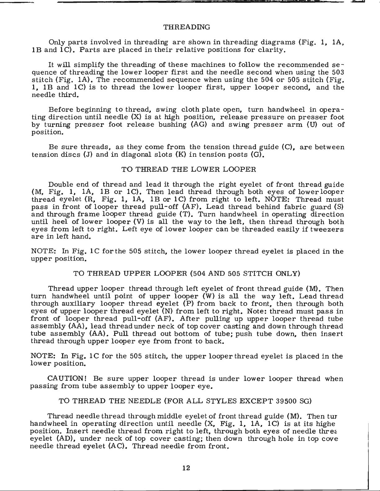
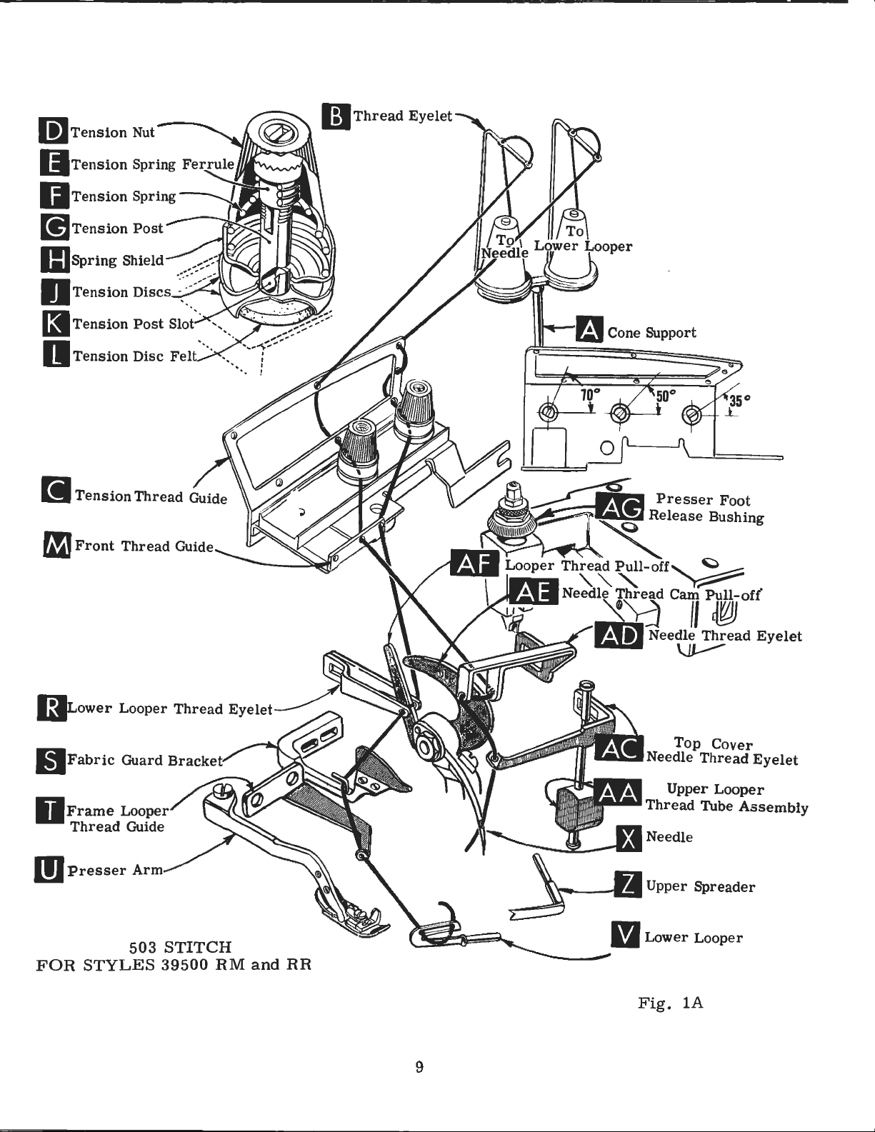
THREADING
Only
1 B
and
It
quence
stitch
1,
needle
ting
by
position.
tension
(M,
thread
pass
and
until
eyes
are
(Fig.
lB
Before
direction
turning
Be
Double
Fig.
in
through
heel
from
in
left
parts
1 C}.
will
of
threading
and
third.
sure
discs
1,
eyelet
front
of
left
hand.
involved
Parts
simplify
lA}.
The
lC}
is
to
beginning
until
presser
threads.
(J}
and
end
of
lA.
lB
(R,
Fig.
of
looper
frame
lower
to
right.
in
threading
are
placed
the
threading
the
lower
recommended
thread
to
thread,
needle
foot
in
thread
looper
looper
(X}
release
as
they
diagonal
TO
and
or
lC}.
1.
lA.
thread
thread
Left
(V}
in
their
of
looper
the
lower
swing
is
at
bushing
come
slots
THREAD
lead
Then
lB
or
pull-off
guide
is
all
eye
of
are
relative
these
first
sequence
looper
cloth
high
it
position,
from
(K}
THE
through
lead
lC)
(AF}.
(T).
the
lower
shown
machines
and
(AG)
the
in
LOWER
thread
from
way
looper
in
positions
the
when
first.
plate
and
tension
tension
the
right
Lead
Turn
to
threading
to
follow
needle
using
upper
open,
release
swing
thread
posts
LOOPER
right
through
handwheel
the
can
eyelet
to
thread
left,
be
threaded
diagrams
for
clarity.
second
the
504
looper
turn
pressure
presser
guide
(G}.
both
left.
behind
then
the
recommended
when
or
505
second,
handwheel
on
arm
(C}.
of
front
eyes
NOTE:
fabric
in
operating
thread
easily
(Fig.
using
presser
are
thread
of
lower
Thread
through
if
the
stitch
and
in
opera-
(U}
between
looper
guard
direction
tweezers
1.
se-
(Fig.
foot
out
guide
must
both
lA,
503
the
of
(S}
NOTE:
upper
turn
through
eyes
front
assembly
tube
thread
NOTE:
lower
passing
handwheel
position.
eyelet
needle
In
position.
Thread
handwheel
auxiliary
of
upper
of
assembly
through
In
position.
CAUTION!
from
TO
Thread
(AD).
thread
Fig.
TO
THREAD
upper
looper
looper
(AA},
upper
Fig.
tube
THREAD
needle
in
operating
Insert
under
eyelet
lC
for
looper
until
looper
thread
lead
(AA).
1 C
for
Be
assembly
thread
needle
the
point
thread
thread
Pull
looper
the
sure
THE
direction
thread
neck
(AC).
505
stitch,
UPPER
thread
of
thread
eyelet
pull
-off
under
thread
eye
505
stitch,
upper
to
NEEDLE
through
from
of
top
Thread
LOOPER
through
upper
eyelet
(N}
(AF}.
neck
out
from
looper
upper
(FOR
middle
until
right
cover
needle
the
lower
(504
left
looper
(P}
from
After
of
top
bottom
front
the
upper
thread
looper
ALL
eyelet
needle
to
casting;
from
looper
AND
eyelet
(W}
from
left
pulling
cover
of
to
back.
looper
is
eye.
STYLES
of
(X,
left.
then
front.
505
of
is
all
back
to
right.
casting
tube;
under
front
Fig.
through
down
thread
STITCH
front
the
to
front,
Note:
up
upper
and
push
thread
lower
EXCEPT
thread
1,
lA,
both
through
eyelet
thread
way
thread
looper
down
tube
eyelet
looper
guide
lC)
eyes
is
placed
ONLY}
guide
left.
then
down.
39500
through
is
(M}.
is
of
hole
through
must
placed
at
needle
(M).
Lead
thread
then
thread
SG)
Then
its
in
top
in
Then
thread
both
pass
tube
thread
insert
in
when
tur
highe
three
cove
the
in
the
12

TO
THREAD
THE
NEEDLE
(FOR
STYLE
39500
SG)
Thread
handwheel
Insert
top
Thread
tension
secure
formly
increase
foot,
(B).
ing
When
set,
throat
surface
1. 59
Set
needle
cover
needle
The
nuts
proper
Sufficient
should
loosen
Adjusting
increases
pressure
tighten
plate,
is
mm)
cap
(.D)
needle
in
operating
thread
casting;
from
amount
or
approximately
from
against
of
{D,
Fig.
stitch
PRESSER
presser
be
decrease
lock
nut
screw
pressure,
adjusting
lock
position
the
nut
thread
from
then
front.
tension
formation.
maintained.
(A,
top
locking
through
direction
back
through
on
1,
lA,
FOOT
foot
amount
Fig.
has a right
loosening
screw
{A).
With
locking
1/32
surface
nut
middle
until
to
front
needle
THREAD
the
needle
lB,
lC).
PRESSURE
pressure
Should
of
pressure
2)
and
hand
{B)
presser
nut
inch
of
{C).
eyelet
needle
of
thread
TENSION
and
Tension
to
feed
it
be
turn
adjusting
thread
decreases
has
been
fo.ot
(C)
so
that
to
1/16
adjusting
of
(X,
Fig.
needle
pull-off
looper
on
work
necessary
on
presser
so
tighten-
pressure.
properly
resting
its
inch(.
screw
front
lB)
thread
eyelet
threads
threads
uni-
screw
on
under
79
{B).
thread
eyelet
to
to
is
at
(AB)
is
should
guide
its
(AD),
regulated
(M).
highest
from
be
only
Fig.
Then
under
right
by
enough
turn
position.
neck
knurled
2
to
of
left.
to
Feed
approximately
feed
39540
of
stitches
chine
to
exploded
Generally
of
stitches
and
direction
Following
5,
6,
40,
50, 60,
tional
39
540 B
Example: 1139540
eccentrics
eccentric
B-12.
Style
7,
eccentrics
Minor
obtainable
39500
views
produced;
8,
9,
70,
with a minor
12
is
speaking,
of
stitch
10,
used
stitches
No.
numbers
QA
in
stretch
11,
100.
may
B-12".
ASSEMBLING
in
39540
when
will
be
catalog
differential
main
Only
{left
of
material
number
12,
be
number
per
13,
two
ordered
FEED
Style
inch.
B-10
of
the
using
shipped
for
hand)
feed
14,
eccentrics
suffixed
AND
ECCENTRICS
39500
part
that
eccentrics
eccentrics
15,
QA
It
will
while
symbol
eccentric.
with
{right
feed
being
16,
separately.
ADJUSTING
machines
be
noted
that
of
above
furnished
hand)
eccentric
sewn,
are
18,
20,
are
supplied
to
indicate
have
that
differential
indicate
Unless
combination
on
feed
eccentric
is
selected
or
type
available
22, 24, 26,
To
order
number
SEWING
been
selected
the
part
feed
approximately
otherwise
other
of
operation.
under
with
each
an
PARTS
number
eccentric
of
eccentrics.
styles
determines
in
relation
28,
eccentric
of
stitches
to
the
specified,
of
machines.
to
No.
39540
30,
32,
machine.
produce
of
main
is
No.
number
ma
Refer
number
degree
B-4,
34,
36,
Addi-
use
No.
desired.
-
Before
chip
procedure
guard,
assembling
upper
that
begins
knife
on
and
adjusting
assembly,
the
next
sewing
lower
page.
13
parts,
knife
remove
holder
cloth
assembly,
plate,
fabric
then
guard,
follow
the

SETTING
THE
NEEDLE
With
needle
looper
take
cept
5)
into
up
On
Style
bar
slot.
thread
end
all
stroke,
center
of
21225-1/8.
dle.
Tighten
throat
Fig.
of
39500
(B).
set
needle
When
pull
play
the
looper
Do
not
nut
plate
assembled
needle
3
-off
back.
in
needle
Styles
TH,
With
covered
insert
lower
point
(Fig.
5),
havelowerlooper
(C).
is
at
When
driving
lower
looper
1/8
inch
using
in
high
(12.
39500
and
RR,
above
Fig.
has
throat
laps
arm.
in
at
(3.
looper
position,
position,
70
mm)
QA,
TD;
15/32
SF
and
the
throat
3)
by
been
set
plate.
If
needle
looper
re
tightening
this
catalog
looper
left
17
mm)
gauge
deflecting
needle
needle
above
QB,
QP,
inch
TH.
To
plate,
loosening
properly,
thread
thread
looper
ex-
(A,
Fig.
end
of
its
from
No.
nee-
should
point
throat
QY.
(11.
align
move
clamp
tighten
cam
pull-off
center
plate
RF,
91
mm)
needle
screw
pull-off
(B),
pull-off
should
(A,
RM,
for
needle
screw
separate
screw,
in
the
be
Fig.
RS,
Styles
or
driving
(C).
(C)
(A.
set
3)
set
After
Fig.
front
for
SE,
39500
the
and
by
be
end
1/2
Styles
SG,
height
arm
needle
remove
4)
over-
moving
sure
of
inch
TA
RA,
(B,
to
On
(A,
Fig.
end
of
mm)
gauge
from
No.
deflecting
Now
looper
until
(.
051-.
moves
the
machine
5)
into
its
stroke,
center
21225-3/32.
needle.
assemble
Fig.
needle
102
mm).
Style
bar
5
to
the
springs
39500
(B).
With
set
looper
of
needle
Do
Tighten
differential
right,
forward
TH
insert
lower
point
(Fig.
not
have
nut ( C).
(front)
possible,
er
position
(.
needle
between
its
point
5).
or
051-.
should
from
lower
looper
3/32
inch
using-
lower
feed
SETTING
Set
rear
without
movement
to
102
guard.
rear
SETTING
Now
finish
rear
looper
at
(2.
looper
looper
dog
to
needle
deflect
mm).
needle
be
set
guard
left
38
all
Styles.
THE
interfering
of
lower
needle
Screw
Make
guard
THE
lower
into
surface
REAR
guard
sure
LOWER
looper
the
NEEDLE
(A,
with
knife
Fig.
Fig.
either
holder,
4
GUARD
6)
forward . 002-.
(B)
is
there
and
uBed
is
lower
to
no
interference
looper.
LOOPER
adjustment.
needle
scarf
another . 002-.
as
lower
but
004
set
As
(A,
004
high
loop-
still
lower
Fig.
as
in
inch
rear
7)
inch
14

SETTING
THE
FRONT
NEEDLE
GUARD
Assemble
looper
guard
(D)
is
setting
guards
Fig.
for
Styles
When
upper
shank
QY,
RA,
Styles
position
is
springing
as
close
used
to
make
and
differential
7
39500
the
looper
slightly
RF,
39500
the
front
needle
needle
as
possible
adjust
sure
and
there
its
er
pushed
shank.
upper
in
holds
shaft.
so
inch
(Fig.
SE,
QP,
upper
looper
holder
back
of
RS, SE, SG,
RR
and
SF
upper
looper
set
is
feed
SETTING
Insert
holder.
in
place.
that
SG,
QY,
should
vertical
upper
shank
guard
off
to
needle
front
no
interference
dog.
its
holder,
in
or
Insert
looper
Screw
the
Locate
the
(.
79
to
8),
for
TA
RA,
is
at
be
TA,
looper
(C.
Fig.
backguard,
without
needle
THE
upper
Screw
looper
(B)
and
out,
or
upper
shaft,
(C.
upper
looper
upper
shank
1.
extends
59
mm)
Styles
and
TD,
RF,
RR.
the
right
set
to
position
on
Styles
TD
and
holder
about
vertically.
6).
set
touching.
guard.
between
UPPER
holds
permits
turned
looper
if
it
Fig.
looper
beyond
39500
and
SF
and
end
39500
TH
should
When
front
After
LOOPER
(A,
Fig.
upper
around
holder
is
not
8)
on
holder
in
its
1/32
QA,
1/16
TH.
of
its
upper
QA,
(Fig.
lower
needle
Screw
this
needle
8)
loop-
it
to
into
already
clamp
in
holder
to
1/16
holder
QB,
to
3/32
stroke,
looper
QB,
8).
be
set
in
be
its
the
RS,
QP,
On
inch
to
(1.
59
Fig.
to
2.
6
38
mm)
Be
of
looper
upper
set
lower
ance
looper
upper
looper
(Fig.
As
the heel
1/32
inch(.
sure,
the
of
Fig.
on
and
casting.
shaft
looper
eye
9).
upper
the
40
9
all
and
point
with . 002
looper
upper
to.
79
styles,
By
adjusting
by
turning
to
cross
there
moves
looper
mm)
clearance.
Next,
travel;
needle
it
by
moving
represents
RS,
SE,
NOTE:
ar e
9/64 and
39500
(3.
57
QY,
mm
settings
is a clearance
the
lower
to • 004
toward
should
turn
check
and
throat
the
SG,
For
Styles 39500
RA
and
are
9/64
looper
looper
looper
(. 051
to • 102
the
pass
behind
handwheel
dimensions
plate
the
upper
dimensional
TA
and
TD.
35/64
and
RF,
12.
70
and
holder
around
to
top
of
(Fig.
looper
QP and
inch
the
mm).
15/32
between
in
or
its
the
left
mm)
of
its
the
lower
until
looper
upper
10).
holder
setting
(3.
57 a
settings
For
inch
heel
out
shank,
of
the
clear-
stroke,
looper
If
r e
for
TH
the
nd
Styles
(3.57
of
Fig.
looper
is
setting
(A.
at
the
point
Fig.
Styles
head
left
with
is ne
1 O).
39500
with
end
r e
cessary,
Figure
QA,
dimensional settings
13.
89 m m
are
39500
and
11.91
9/64
RR
). For
and
and
mm).
1/2
8
1/64
of
spect
Style
RF
to
its
to
do
10
QB,
s
inch
the
15

SETTING
For
(12.
30
looper
from
inch
upper
looper
made
looper
tain
the
THE
example,
mm)
holder
left
end
(3.
97
looper
shaft.
it
may
around
condition
UPPER
LOOPER
dimension
in
increased
counterclockwise
of
machine;
mm)
is
increased
holder
After
be
necessary
its
these
shank
shown
(Continued)
31/64
by
turning
dimension5/32
by
left,
out
changes
to
turn
slightly
in
Fig.
upper
looking
pulling
of
upper
upper
to
main-
9.
inch
are
Fig.
level
SG,
NOTE:
looper
with
TA
and
For
and
Check
downstroke.
slightly
of
machine.
and
SETTING
Insert
(B)
holds
pushed
holder
Fig.
and
in
into
8A)
allows
on
10
top
surface
TD.
Styles
needle
setting
If
needle
rotate
Reset
THE
upper
upper
or
out,
spreader
clamp
holder
When
it
can
upperlooperismovingtotheright,
upper
bottom
of
upper
39500
should
to
QP, QY,
align
avoid
rubs
looper a short
to
maintain
UPPER
SPREADER
spreader
spreader
or
turned
shaft,
collar
to
be
in
if
holds
rotated
the
correct
be
checked
looper
of
the
eye
needle
looper
RA,
exactly.
interference
the
back
distance
dimensions
(A,
Fig.
its
around
it
is
8A)
holder,
its
not
already
spreader
or
adjusted
(Fig.
of
upper
(FOR
shank.
centers
setting
quickly
eye
11)
RF,
RR,
between
is
as
follows:
on
the
should
for
SF
upper
looper,
counterclockwise,
of
Figs.
9,
STYLES
in
its
holder.
and
permits
Insert
in
place.
holder
in
laterally.
obtained,
when
needle,
be
about
Styles
and
TH,
looper
pull
10, 11.
39500
Screw
it
to
spreader
Screw
the
(C.
shaft,
As
39500
the
and
looper
looking
RM
AND
be
QA,
eyes
needle
out
RR
Fig.
QB,
of
of
its
from
ONLY)
RS,
the
on
left
11
SE,
upper
needle
holder
end
Preliminary
end
of
spreader
of
spreader
mm)
is
set
true
to
above
position
should
Style
39500
As
pass
mm)
just
clearance
its
stroke,
shank
shank
the
of
Style
extend
RR.
spreader
behind
Setting:
spreader
slightly
should
spreader
39500
s~reader
1/16
to
moves
the
between
back
holder
RR
except
shank
3/32
eye
spreader
When
holder
extend
inch
from
of
the
upper
spreader
should
of
vertical
1/32
to
1/16
for
the
Style
spreader
39500
approximately
(1. 59
right
lower
and
to
to
left,
looper,
lower
be
(Fig.
inch
2. 38
the
looper
is
at
set
to
8A).
(. 79
RM.
The
holder
vertical.
mm)
Vee
with . 002
(Fig.
should
above
16
the
right
position
Top
end
to
1. 59
same
Top
the
notch
to . 004
9A).
be
end
of
of
spreader
spreader
the
spreader
inch
Fig.
(.
051
8A
shank
holder
should
to . 102
for

SETTING
THE
UPPER
SPREADER
(Continued)
(FOR
STYLES
39500
RM
AND
RR
ONLY)
Turn
end
of
spreader
left
of
the
its
travel.
should
the
centerline
mately 7 /16
l0A)
for
Style
the
lower
inch
and
(3.
should
throat
Now
dle.
If
out
of
ward
opposite
to
lower
Fig.
the
same
point
57
plate.
check
needle
its
holder
a
short
movement.
looper
l0A
time.
hand
inch
39500
mm)
be
15/32
wheel
At
this
extend
of
(11.
RM.
of
the
to
the
inch
setting
rubs
the
slightly
distance.
will
(Fig.
if
feed
B,
plane.
edge.
ed
(D).
until
position,
about
the
needle
11
mm)
Style
spreader
left
of
(11.
between
back
and
These
reduce
9A).
Now
not
already
dog ( C).
On
Styles
C,
Fig.
This
Now
with
throat
This
upper
spreader
the
5/32
inch
and
above
39500
should
the
centerline
91
mm)
upper
of
spreader,
rotate
same
the
assemble
in
39500
12)
so
can
be
assemble
plate
pin
raises
lower
(3.
should
the
throat
RR
is
the
extend
above
spreader
spreader
adjustments.
clearance
SETTING
differential
place,
QA,
the
checked
throat
surface
or
is
point
97
mm)
be
plate
same
about
of
the
pull
holder
main
RS
top
surfaces
by
lowers
at
the
of
to
approxi-
(Fig.
except
the
needle
top
of
and
spreader
between
THE
(back)
and
sighting
plate.
by
rotating
the
lef1:
the
the
9/64
the
nee-
for-
in
spreader
FEED
(front)
TD,
of
Feed
back
DOGS
feed
feed
set
all
teeth
across
dogs
feed
end
and
dog
dog
(B)
three
all
teeth
should
tilting
of
both
Fig.
A
9
needle.
(A.
Fig.
and
chaining
feed
dogs
lay
in
the
with a straight
now
be
level-
adjusting
feed
bars
Reset
12).
(A,
same
pin
at
The
plate.
teeth
the
differential
NOTE:
set
chaining
feed
Screw
rise
On
dogs
(E)
about
Styles
feed
locks
3/64
feed
39500
dog
should
feed
inch
dog
(C)
be
set
tilting
(1.
should
QB,
QP,
level
19
rise
with
Fig.
level
adjusting
mm)
1/32
QY,
top
at
the
above
inch(.
RA,
of
12
time
pin
throat
RF,
throat
teeth
in
place.
79
RM,
plate
plate,
mm)
RR,
travel.
NOTE:
Style
39500
TA
does
not
use a chaining
feed
dog.
17
first
Now
except
above
SE,
when
appear
set
throat
SF,
feed
above
feed
on
SG,
is
Style
plate.
at
the
the
dogs
39500
TA
top
throat
so
and
of
that
SG
TH,
its

SETTING
THE
LOW
ER
KNIFE
with
back
Replace
cutting
Fig.
from
edge
the
lower
13
cutting
knife
flush
holder
with
edge.
assembly.
throat
gonal
knife
lateral
changed.
tightening
port
pin
for
be
locked
ed
against
(D,
Fig.
(F)
in
At
bottom
knife
below
should
plate
head
is
spring
adjustment
Lower
bracket.
the
with
(FOR
Replace
13)
its
most
should
cutting
be
set
Lower
surface.
screw
pressed
knife
screw
(B)
Because
cloth
plate
nut
lower
knife
SETTING
ALL
upper
in
position,
clockwise
of
its
stroke,
extend
edge
down
knife
Adjustments
which
is
necessary
may
be
and
locking
screw
latch
(C)
even
holder.
THE
STYLES
knife
assembly.
setting
position
front
not
less
of
lower
against
(A,
Fig.
holds
against
secured
(B)
spring.
when
UPPER
EXCEPT
than
knife.
the
upper
13)
are
lower
upper
when
in
nut
also
screw
KNIFE
Clamp
nut
(E)
against
cutting
1 /
64
The
knife
should
made
knife.
width
any
(C)
serves
it
should
is
39500
to
edge
inch
chain
with
knife,
of
position
against
as
not
tighten-
SF)
upper
hold
upper
of
(.
guard
and
be
set
hexa-
Lower
so
no
trim
is
by
sup-
latch
always
knife
clamp
knife.
upper
40
mm)
(G)
slightly
After
tightened
when
upper
Replace
located
front
below
cutting
cutting
After
width
of
locked
ing
block.
Length
of
feed
14)
actuates
eccentric
upper
to
lock
knife
upper
on
the
right
edge
edge
the
trim,
in
place
SETTING
of
eccentrics
main
(B)
actuates
knife
upper
is
replaced.
SETTING
knife
side
of
of
upper
the
upper
using
stitch
used.
(rear)
has
knife
assembly.
to
hold
upper
the
lower
knife
knife
the
screw
THE
is
STITCH
determined
Outer
feed
the
differential
been
set
holding
UPPER
clamp
knife
knife.
has
been
holding
at
(left)
dog;
for
proper
block
KNIFE
Clamp
against
should
set
block
the
front
LENGTH
by
the
eccentric
while
the
(front)
width
(J)
in
(FOR
upper
knife
the
extend
for
the
should
of
the
combination
(A,
inner
feed
of
place.
STYLE
in
upper
not
less
proper
be
hold-
Fig.
(right)
dog.
trim,
This
39500
position,
knife.
than
will
SF)
At
screw
simplify
setting
bottom
1/64
(H)
Allen
of
inch
should
resetting
screw
its
stroke.
(. 40
be
mm)
In
·
facing
key.
assembling
each
Tighten
other.
nut
feed
Be
(C)
eccentrics,
careful
securely.
not
be
to
damage
sure
hubs
shaft
are
or
18
Fig.
14

To
Turn
Using
as
necessary
slightly
addition
Fig.
move
Then
handwheel
hooked
shown
If
eccentrics
15)
nut
continue
change
and
to
during
to
removing
from
(G)
SETTING
feed
eccentrics,
in
operating
eccentr
withdraw
move
extraction.
are
shaft
and
as
(E),
feed
originally
ic
extractor
eccentrics.
handwheel
unusually
nut
(C)
it
may
driving
suggested.
THE
STITCH
remove
direction
(F),
back
tight
and
be
helpful
connection
nut
until
supplied
It
may
and
fitting,
washer
LENGTH
(C)
and
key
with
be
forth
in
(D,
to
re-
(H).
(Continued)
washer
slot
in
machine,
(D)
from
eccentric
reach
end
is
toward
behind
of
shaft
front.
eccentrics
(E).
Assemble
With
arm
foot
flat
with
the
aligned
locked
assemble
position.
needle
into
to
on
front
presser
SETTING
sewing
align
throat
with
with
needle
edge
foot
throat
Fig.
nut
chip
the
in
high
plate.
of
be
(F).
guard,
THE
PRESSER
presser
position,
position
holes
The
front
needle
flat
plate
16
hole
on
slots
Re-assemble
turn
FOOT
foot
to
presser
swing
and
set
(front
the
handwheel
edge
in
throat
throat
by
and
shifting
the
arm.
presser
the
presser
back)
of
needle
plate.
plate.
the
move
16)
lifter
quired.
screw.
the
presser
er
presser
looper
There
to
before
adjustment
until
and
foot
3.
chip
the
The
collar
Adjust
17
upper
and
hole
It
is
If
necessary,
foot
shaft,
clamp
lever
Retighten
foot
(B)
arm
release
lifter
foot
will
should
mm)
the
presser
should
guard,
knife
in
presser
also
lifter
loosen
screw
shaft
lifter
secure
does
can
not
bushing
lever
be
permit;
be
from
free
fabric
assembly
foot
important
presser
lever
to
collar
lever
raised
motion
be
collar
(G)
the
the
bind
is
stop
then
1/16
foot
made
guard
shaft
and
arm
and
begins
Fig.
left
unlocked.
no
of
l 5
must
that
foot
(H,
screws
then
or
screws
(A,
shaft.
rise
screw
higher
lock
to
1/8
foot
with
and
cloth
reaches
to
screw
be
the
can
Fig.
shift
right
and
Fig.
Be
when
(C)
than
the
inch
lifter
rise.
its
aligned
bottom
be
16).
(B,
the
as
clamp
16)
sure
press-
so
upper
nut
(1.
lever
(E)
plate.
highest
of
re-
To
Fig.
foot
re-
and
the
that
(D).
59
This
and
To
Be
stitch
looper
mately
chin
e s
off
stitch
slowly.
sure
machine
or
according
thread
horizontal
lowly
..
tongue
STARTING
eyelet
and
without
freely.
is
to
(R,
in
presser
TO
threaded
Fig.
Fig.
the
Swing
1
lA)
middle
OPERATE
according
for
the
or
looper
of
foot
in
presser
504
their
place,
foot
19
(503
to
threading
stitch.
thread
front
to
into
AND
With
eyelets
to
make sure
position,
504
STITCH)
diagram
thread
(N
back
Fig.
tensions
and
R,
locations.
chain
insert
forms
material
lA
for
light,
Fig.
1)
approxi-
Operate ma-
and
the
moves
and
503
set
sew

NEEDLE
THREAD
CONTROL
(503
AND
504
STITCH)
While
needle
should
slightly
stroke,
off
(AE)
It
tor)
to
With
back
treme
inch
extreme
back
its
mm)
should
looper
and
Frame
(3.
With
far
most
distance
sewing
thread
be
just
if
excessive
position
just
is
desirable
delay
material
down
left
position.
1 7
mm)
left
material
enough
rearward
be
set
(V)
heel
is
tight
needle
contacts
slightly,
LOW
far
looper
to
end
LOWER
so
behind
with
eyelet
on
material,
drawn
enough
thread
needle
to
adjust
ER
under
enough
Lower
thread
the
right
of
its
under
thread
position.
needle
its
eyelet
at
on
to
thread
the
tightening
LOOPER
presser
so
looper
guide
of
travel.
LOOPER
presser
is a little
thread
the
check
needle
feed
is
pulled
eyelet
thread.
the
needle
thread
(T)
heel
Looper
approximately
time
needle
down
chain
on
(AD,
thread
of
the
THREAD
foot,
thread
eyelet
THREAD
foot,
cam
lower
set
is a little
should
slack
thread
pull-off
thread
stroke.
off
stitch
the
Fig.
eyelet
needle
CONTROL
lower
eyelet
be
set
of
looper
CONTROL
set
lower
when
pull-off
1/8
looper
up
stroke.
1)
thread.
looper
slack
(R)
with
looper
(AE).
inch
is
control
At
top
of
tongue.
so
well-forward
when
should
(V)
looper
(AF)
Frame
(3.
at
extreme
that
(503
thread
its
at
the
(504
thread
thread
is
17
mm)
Stitch
With
needle
STITCH)
spreader
be
eyelet
STITCH)
set
as
follows:
needle
tends
needle
thread
(toward
eyelet
about
approximately
time
lower
eyelet
pull-off
about
looper
to
the
left
end
Usually
stroke,
to
pull
at
bottom
cam
the
(R,
Fig.
reaches
horizontal.
looper
(R,
(AF)
1/32
thread
right
of
inch(.
guide
of
its
all
thread
down
pull-
opera-
lA)
its
ex-
1 / 8
is
Fig.
reaches
79
(T)
lower
travel.
of
at
1)
While
portion
looper
the
tension
eyelet
Before
three
will
not
During
draw
is
pull-off
Fig.
to
upper
drawn,
To
1)
have
If
all
end
that
it
to
form
edge.
sewing
of
lower
thread
while
(R)
down,
proceeding
tensions
markedly
needle
looper
upper
reaches
move
should
slightly
it
becomes
play
is
in
higher
near
on
looper
comes
lower
keeping
UPPER
to
give a normal
affect
down
thread
looper
its
most
the
purl
be
raised
more
necessary
needle
over
top
edge.
material,
thread
off
upper
looper
the
LOOPER
to
adjust
the
stroke,
through
thread
rearward
POSITIONING
more
keeping
pull-off
drive
throat
If
upper
check
should
looper.
thread
same
THREAD
upper
appearing
purl.
forward
will
under
the
on
upper
to move looper
shaft before
plate
looper
is
amount
the
tension.
have
position.
THE
the
same
than
is
drawing
be
drawn
To
increase
on
upper
of
CONTROL
looper
stitch.
stroke
almost
PURL
edge,
thread
tightening.
recommended
too
off
pull
-off
thread
of
When
all
(504
both
amount
than
thre
ad
low,
through
looper,
Moderate
of
looper
amount
action.
(504
eyelet
looper
normal
slack
STITCH)
looper
of
pull-off.
on
lower
pull-off
If
in
the
purl
the
of
move
STITCH)
change
thread
amount
taken
thread
(AF),
upper
Fig.
will
thread
tension
thread
lower
(N,
Fig.
up
eyelets
Usually
thread.
be
loop
10,
the
form
as
before
drawn
looper
1)
in
these
pull-off
of
looper
as
looper
sure
er
is
purl
nearer
follows:
lower
through
thread
balance
tensions
(AF)
thread
thread
(N
and
it
is
better
to
take
located
will
bottom
A
all
will
R,
up
so
tend
20

THREAD
TENSIONS
(503
STITCH)
Balance
these
The
being
ble
without
should
purl
Be
lC).
With
about
Operate
forms
Swing
tensions
needle
sewn.
be
increased
is
pulled
sure
thread
horizontal
and
moves
presser
both
will
thread
In
general,
causing
too
machine
tensions
and
machine
tensions
not
markedly
tension
needle
as
far
over
STARTING
is
in
the
slowly,
off
the
foot
into
NEEDLE
to
give a normal
THREAD
lower
long
tongue
looper
thread
as
the
top.
threaded
light,
middle
without
position,
THREAD
affect
TENSIONS
required
thread
to
be
the
elasticity
TO
OPERATE
according
set
upper
of
their
presser
freely.
appearing
the
purl.
(504
is a function
tension
pulled
to
and
lower
front
foot
insert
CONTROL
materials,
STITCH)
down.
of
the
(505
threading
looper
to
back
in
(505
stitch.
of
needle
should
Upper
chain
STITCH)
thread
locations.
place,
and
STITCH)
Moderate
thread
be
set
as
looper
increases,
diagram
eyelets
to
make
sew
slowly.
and
high
thread
or
(Fig.
sure
change
material
as
possi-
tension
until
1,
lB
(N
and
that
chain
in
the
or
R)
of
needle
Fig.
the
way
inch
at
the
or
1 C)
looper
Position
upper
While
To
increase
1,
lB
Set
lower
forward
Frame
(3.
17
left
With
to
thread
looper
sewing
thread
or
lC)
LOW
looper
looper
mm)
end
of
UPPER
material
rest
on
is a little
of
thread
on
material,
required
thread
farther
ER
in
its
thread
to
the
its
stroke.
under
top
of
POSITIONING
lower
tensions.
for
drawn
to
LOOPER
thread
slot.
guide
right
LOOPER
presser
lower
slack
looper
check
the
on
the
eyelet
(T)
of
lower
looper
when
THE
thread
needle
stitch
rear.
THREAD
THREAD
foot,
should
downstroke,
(R,
should
looper
set
thread
upper
SQUARE
at
the
thread
be
CONTROL
Fig.
1,
be
set
(V)
CONTROL
upper
eyelet
looper
EDGE
edge
control
drawn
position
lB
or
with
heel
looper
is
eyelet,
(R),
reaches
(505
located
on
needle
(505
lC)
its
eyelet
(505
thread
and
the
STITCH)
as
follows:
needle
thread
STITCH)
about
STITCH)
back
by
horizontal
approximately
when
eyelet
far
left
balancing
About
downstroke.
eyelet
lower
enough
end
(N,
of
looper
Fig.
so
its
needle
60%
(AD,
and
all
1/8
1,
lB
upper
stroke.
and
is
To
increase
reduce
lower
amount
looper
of
lower
thread
looper
tension.
thread
in
the
stitch,
21
or
close
the
edge
more,

TO
REMOVE
Fig.
17
CRANKSHAFT
Crankshaft
1.
Drain
of
2.
Remove
3.
Remove
eccentric
4.
Remove
5.
Remove
will
6.
Remove
through
can
oil
base.
be
re-assembled
bottom
be
withdrawn
by
removing
top
and
feed
key
screw
eccentric
extractor,
(D).
three
easier
plug
bottom
counterweights
(F)
of
bed
nut
slip
in
which
casting.
covers
(A.
off
the
holds
screw
of
Fig.
the
(E).
proper
crankshaft
if
these
located
machine.
eccentrics ( C).
steps
17)
and
Identify
places.
on
back
washer
these
split
are
bearing.
22
followed:
of
machine
(B),
and,
counterweights
This
with
screw
near
bottom
the
aid
so
is
edge
of
that
they
reached
the

7.
Remove
crankshaft
W
he n re -assembling
cap::;
original
are
caps
be
ings.
assembled
which
8.
Loosen
which
arm
is
through
ing
knife
cap
precautions
make
stamped
and
on
the
Also,
they
clamp
holds
(B).
arm
driving
(E).
caps
at
points
sure
position.
on
both
trade
same
screws
in
the
were
nut
upper
Access
top
cover.
to
the
lever
This
is
when
TO
REMOVE
of
bearings
G, H,
they
are
Trade
both
halves
marks
side
of
the
should
same
holes
removed.
(A,
Fig.
knife
to
clamp
Draw
left
until
(C)
and
at
bearing
re-assembling
CRANKSHAFT
on
and
J.
bearing
in
their
marks
of
the
should
bear-
be
re-
from
18)
driving
nut
drivupper
connecting
point
(K,
cap
rod
Fig.
as
described
(Continued)
(D)
drop,
17)
Fig.
allowing
on
crankshaft.
in 7 above.
18
removal
of
Observe
bearing
same
9.
10.
11.
12.
13.
14.
15.
16.
Remove
screw
Loosen
is
two
Remove
Loosen
two
Remove
collars
(V)
Crankshaft
If
necessary
arbor
against
press.
ground
Carefully
assembly
various
parts
helpful.
screw
reached
screws
screw
screws
three
and
may
to
In
observing
of
crankshaft.
and
(L,
Fig.
through
(M)
(N);
take
(R);
screws
(W)
may
now
be
replace
replacing
thrust
reverse
constant
17)
bottom
in
fan
off
remove
(T);
be
removed.
ball
bearing
washer
Checking
testing
which
of
collar;
pulley
pulley
take
off
removed
bearing
it
(Y).
of
the
for
holds
bed
remove
cap
(P).
(S).
bearing
at
this
(X),
must
foregoing
exploded
binds
inner
casting.
both
retaining
time.
it
should
be
pressed
during
right
crankshaft
halves
be
on
operations
view
drawings
re-assembly
of
cooling
plate
pressed
carefully
should
(U);
for
will
bearing.
fan.
also,
off
shaft
until
simplify
location
also
This
spacer
on
it
seats
prove
an
re-
of
17.
Before
gaskets.
oil
and
bottom
ing
re-assembling
Before
wick
that
which
it
cover.
to
prevent
re-assembling
lubricates
contacts
Coat
oil
leakage.
thoroughly
shaft.
oil
drain
bottom
left
crankshaft
The
wick
plug
with a sealing
No. 1 Crane
clean
stands
23
and
cover
bearing
Lead
dry
make
vertically
compound
Seal
top
and
sure
is
inserted
on
is
recommended.
bottom
that
in
its
before
covers
spring
hole
in
spring
re-assembl-
and
pressed
casting
against

ILLUSTRATIONS
ORDERING
REPAIR
PARTS
views
in
their
This
catalog
of
various
actual
found a listing
pieces
required
Numbers
the
position
in
ordering
of
parts.
Component
dicated
assembly.
23
24
25
26
27
28
29
30
31
32
33
by
indenting
Example:
29477
29477
29477
22768
22596
22587
51-228
39541
30-106
C067
40-46
258
has
sections
position
of
the
in
in
the
that
parts
JM
KE
MC
C
H
M
Blk.
A
Blk.
E
been
in
parts
the
particular
first
part
in
Always
of
sub-assemblies
their
Crankshaft
for
Crankshaft
for
arranged
of
the
mechanism
the
machine.
with
their
column
the
illustration.
use
the
descriptions
Styles
Styles
Needle
to
part
view
are
reference
part
and
Needle
39500
and
Needle
39500
Driving
simplify
are
On
the
numbers.
being
Reference
number
which
under
QA. QB,
QP,
Arm
ordering
shown
page
shown.
numbers
listed
can
be
the
Driving
RM,
Driving
QY. RA,
Crank
repair
so
that
opposite
description
only.
number
in
the
furnished
description
Arm
RS,
Arm
RF,
Crank
SE.
Crank
RR,
and
Connecting
the
parts
the
illustration
and
and
should
second
for
of
Assembly.
SG,
TA.
Assembly.
SF,
TH-----------
parts.
the
merely
never
column.
repairs
the
TD--------
Assembly-------------------------------------
Screw.
for
needle
driving
arm
connecting
pin---------------------------------------
Vent
Feed
Wood
Cork
Screw.
Screw.
Plug---------------------------------------
Driving
Plug--------------------------------------
Plug--------------------------------------
for
needle
for
needle
Eccentric
driving
driving
Key
arm
arm
crank
connecting
----------
----------------------
Washer-----------------------------------------
Nut--------------------------------------------
may
number
main
Rod
rod
rod---
Exploded
be
seen
will
be
of
indicate
be
used
are
in-
sub-
1
2
1
1
1
1
1
1
1
1
1
1
It
will
be
crank
parts
noted
or
connecting
individually
is
in
rod
not
the
are
recommended,
ordered.
Where
difference
a
part
is
the
will
used
parts
be
shown
in
all
for
all
in
machines
mentioned.
At
the
back
this
book.
the
part
number
Where
On
some
of
identification
of
This
will
is
the
construction
the
smaller
letter
the
book
facilitate
known.
is
stamped
parts.
PARTNUMBERSREPRESENTTHE
IN
WHICH
THEY
APPEAR.
above
the
the
example
not
listed.
styles
illustrations
covered
will
be
found a numerical
locating
IDENTIFYING
permits.
and
on
in
to
distinguish
that
The
so
covered
by
the
each
those
SAME
the
crankshaft,
reason
the
complete
in
this
or
mentioned
this
catalog
illustration
PARTS
part
where
is
construction
the
PART,
is
that
catalog
in
no
index
and
stamped
part
from
needle
replacement
sub-assembly
are
not
the
descriptions.
machine
of
all
the
description
with
its
does
similar
driving
the
style
parts
part
not
ones.
of
should
same.
shown
when
number.
permit,
REGARDLESSOFCATALOG
these
When
will
only
arm
be
the
be
in
an
24

USE
GENUINE
NEEDLES
AND
REPAIR
PARTS
Success
UNION
SPECIAL
poration,
to
the
most
efficiency
Genuine
parts
is
your
are
guarantee
Prices
forwarded
wise
directed.
Torque
a
distance
driver,
amount
unless
by
All
hand
of
straps
otherwise
in
its
subsidiaries
scientific
and
needles
stamped
are
f.
o.
(measured
by a lever
etc.
Many
torque
as
tightly
the
operation
Needles
durability
are
with
of
the
net
cash
b.
shipping
A
charge
(in
of
will
and
eccentrics
noted.
as
possible,
and
and
principles,
are
assured.
packaged
the
Union
highest
and
point.
is
made
TORQUE
in
inch-pounds)
inches
these
tighten
devices
the
should
All
other
of
these
Repair
authorized
and
with
Special
quality
TERMS
subject
to
Parcel
to
cover
REQUIREMENTS
or
feet).
are
part
to
be
nuts,
unless
machines
Parts
as
furnished
distributors.
are
made
labels
marked
trademark,
in
materials
change
p0st
shipments
postage
is a rotating
This
is
available,
the
correct
tightened
bolts,
otherwise
can
be
secured
by
They
with
without
utmost
~ i •
U S
Emblem.
and
workmanship.
notice.
are
and
insurance.
force
(in
accomplished
which
amount
to
19-21
screws,
inch-pounds
etc.,
noted.
the
Union
are
designedaccording
precision.
All
insured
pounds)
by a wrench,
when
and
set
no
should
only
with
Special
Genuine
Each
trademark
shipments
unless
applied
at
the
tighter.
(22-24cm/kg)
be
genuine
Cor-
Maximum
repair
are
other-
through
screw
proper
tightened
The
screws
requiring
a
specific
torque,
will
be
indicated
on
the
picture
plates.
25


MAIN
FRAME,
MISCELLANEOUS
PRESSER
FOOT
COVERS
RELEASE
AND
PLATES
PARTS,
Ref.
No.
1
2
3
4
5
6
7
8
9
10
11
12
13
14
15
16
17
18 22541
19
20 39582 GG
21
22 39582 J
23
24
25
25A
26
27
28
29
30 90
31
31A
32
32A 39568 P
33
34
35
36
37
38
39
40
41
42
43
44
Part
39557 B
39557 E
39557 C
39557 F
39557
39557 A
39563
39563
22569
39556
39582
39582
39582 V
39582
39582 W
22562
39582
22585
39582 H
53634
22565
22565
22569
39594 R
22571
39534
29477 GW
29477
39568 G
39568 J
22743
39501 K
22569
22565
39599
22569
22569
39594 G
39594 H
thru
76
No.
F
T
B
A
AD
AF
AG
51-103
A
AE
G
C
D-8
667
S
D
E
R
HJ
F
69
H
B
Blk.
Description
Presser
Presser
Presser
Lock
Presser
Presser
Top
except
Top
39500
Screw,
Presser
Top
Spring
Spring
Spring
Nut,
Cover
Cover
Cover-----------------------------------------Oil
for
Spring-------------------------------------Spring
39500
QY,RA,SF-----------------------------------
for
Foot
Filler
Plunger
Plunger
Plunger
adjusting
Plunger------------------------------
Needle
Needle
top
Thread
QY, RA,
Thread
cover
Release
Cover
Cap
Nut
----------------------
Locking
Adjusting
screw
Eyelet,
SF,
SG
Eyelet,
needle
Bushing------------------------
--------------------------------
Nut-------------------
------------------------
-------------------------
thread
Screw---------------
for
all
for
Styles
eyelet--------------
Spring-----------------------------------------
Hinge
Hinge
Oil
Screw,
Top
Cover
Screw,
Side
Cover
Side
Cover,
Bracket----------------------------------
Pin---------------------------------------
Guard---------------------------------------
for
for
hinge
Gasket
top
cover---------------------------------
Latch
for
Styles
bracket-------------------------
-----------------------------------
Stud,
for
Styles
39500
RA,
39500
RR,
SF
Spring------------------------------------------
Rivet,
Washer,
Style
Dowel
Set
Screw,
and
for
Spot
Screw,
Screw,
Oil
Collector
Magnetic
Feed
Screw,
Upper
Upper
Cloth
Screw,
Screw,
Tape
Washer,
Screw,
Screw,
Oil
Oil
See
Bar
Styles
39500
Thread
Thread
Thread
Set
Plate
Guide,
Filter
Strainer,
following
for
spring--------------------------------
for
No.
39500
39582 GG
SF-------------------------------------
and
used
with
Pin------------------------------------------ 2
for
upper
upper
for
Oil
Oil
for
Looper
except
Looper
QY
Screw,
for
for
for
for
for
Screen------------------------------------
looper
for
upper
oil
collector
Plate
Drain
Shield
feed
bar
Thread
39500
Thread
only-------------------------------------
Tube,
Tube,
Tube
for
Stud------------------------------------cloth
feed
adjusting
for
tape
tape
guide--------------------------------
oil
filter
felt-----------------------------------page
looper
drive
looper
----------------------------------
Plug
---------------------------------
oil
Tube
QY
Tube
for
No.
for
No.
Tension
thread
plate
Styles
stud
39500
guide-------------------------------
screen
thread
lever
drive
plate-------------------------
Screw------------------------
shield-------------------------
Assembly,
----------------------------Assembly,
29477
29477
Spring----------------------
tube
---------------------------
pin
------------------------RA,
and
tube
shaft----------------
lever
for
for
GW
------------------
HJ-------------------
tension
SF-------------------
strainer---------------
spring
Styles
RA,
RR,
SF
---------------
86 X on
assembly
shaft
---------
all
Style
----------
-----
Amt.
Req.
1
1
1
1
1
1
1
1
2
1
1
1
1
1
1
1
1
1
8
1
1
1
2
1
2
1
1
1
1
1
1
1
1
1
1
1
1
1
1
1
1
2
2
2
1
1
27


MAIN
FRAME,
MISCELLANEOUS
PRESSER
COVERS
FOOT
RELEASE
AND
PLATES
PARTS.
Ref.
No.
1
thru
44
45
46
47 22657
48
48A
48B
48C
49
50
51
52
53
54
55
56
57
58
59
60
61
62
63
64
65
66
67
68
69
70
71
71A
72 90
73
74
75
76
Part
No.
43
86
39578
138
39501
39501 E
39501
39501
41071
39582
39582
22569
39578
39578
39578
39578
22569
22894
39593
660-243
39582
22653
39582
8372
22569
39582
22541
39595
39595
39582
22569
39582
22586
22541
51295
39532
39532
39582
39582
39593
39593
X
F
D-12
D
EB
DB
G
D
DA
D
T
U
AH
TA
K
AE
H
F
D-4
BV
A
C
BM
B
BL
D
BK
T
B
B
A
E
BH
BW
C
D
See
preceding
Screw.
Cloth
Screw,
Screw.
Cloth
Cloth
Cloth
Cloth
Nut,
Feed
Feed
Screw.
Chip
Plate
39500
Plate,
on
all
Plate.
ed
installation
Plate,
39500
Plate,
on
Style
for
Mechanism
y
Q
• • •
Mechanism
Guard,
RR,
Chip
Chip
Chip
Screw,
Screw,
Oil
Oil
Bottom
Screw,
Air
Washer,
Screw,
Base
Screw,
Isolator,
Isolator,
Air
Screw,
Air
Screw,
Screw,
Isolator,
Cloth
Cloth
Screw,
Bottom
Bottom
Oil
Oil
Guard,
Guard,
Guard,
Sight
Gauge
Duct,
Plate---------------------------------------
Duct,
Duct,
Plate
39500
Plate
Gauge
Gauge
Description
page
for
feed
RR,
for
for
Styles
SF---------------------------------------
39500
feed
RA
RR
for
SG,
TH------------------------------------
for
oil
for
lower
Gauge-----------------------------------
Seal
Cover
for
bottom
upper
for
for
upper
for
base
for
for
outer-----------------------------------
for
lower
lower
for
bottom
for
bottom
for
SF---------------------------------------
for
latch
Cover
Cover
Float-----------------------------------
Indicator-------------------------------
mechanism
Fabric
SF-----------------------------------
cloth
cloth
for
for
for
for
mechanism
Guard,
plate
plate-----------------------------
semi
except
Style
on
non
semi
SF--------------------------------
Cover,
fabric
or
39500
39500
all
Styles
submerged
or
cover
for
guard
fully
RR,
RR
except
fully
cover---------------------
for
all
------------------
all
Styles
submerged
SF-----------------
and
installation
submerged
Styles
SF--------------------------------
Cover,
chip
guard-----------------------------
for
all
Styles
for
Styles
for
Style
for
Styles
sight
looper
Ring-------------------------------
Extension---------------------------
cover
----------------------------------
upper
all
Style
all
Latch
Latch
air
air
plate
Styles
39500
and
---------------------------------cover---------------------------
cover---------------------------12
Styles
Spring,
Spring.
spring----------------------------
Gasket------------------------------
------------------------------------
for
Style
except
39500
39500
39500
gauge
duct
duct--------------------------
----------------------------except
outer
except
RF-5/32
--------------------
bar
driving
extension------------------
------------------------
TA
-----------------------
air
for
for
39500
39500
RR,
SG
RA.
TH---------------
39500
duct-----------------
39500
all
Styles
Style
except
----------------installation
for
non
submerg-
39500
lever
TA-------------
TA-------------
39500
SF-------- 1
on
installation
except
QY
RA,
--------------only-----------
except
39500
---------
RF-5/32,
shaft------
SF--------- 1
Style
-----
Amt.
Req.
1
1
2
1
1
1
1
1
1
1
2
1
1
1
1
1
2
1
1
1
2
1
2
2
1
2
2
4
1
4
1
1
2
1
2
1
1
1
1
29

A-NEEDLE
B-UPPER
C-UPPF.R
D-LOWER
DRIVE
LOOPER
KNIFE
LOOPER
BEARING
DRIVE
DRIVE
DRIVE
BEARING
BEARING
BEARING
30

CRANKSHAFT
MECHANISM AND BUSHINGS
Ref.
No.
1
2
3
4
5
6
7
8
9
10
11
12
13
14
15
16
17
18
19
20
21
22
23
24
25
26
27
28
29
30
31
32
33
34
35
36
37
38
39
40
41
42
43
44
45
46
47
48
49
50
Part
No.
22769 B
39521
D
39521 G
95
22569
B
39590 H
39590 S
39590 R
660-268
39590
G
39590 J
39591 L
39591 H
22894 D
39590 X
660-443
660-204
39590
P
77 Q
22565 F
39590 D
97 A
29477
JM
29477 KE
29477
MC
22768 C
22596 H
22587 M
51-228
39541 A
30-106
C067
E
40-46
258
39591
B
22747 B
39590 N
39591 A
39591 K
87 U
39594 N
666-94
39590
39590
T
39544 X
39552 P
39573
AA
39555 N
39555 P
39573 K
39552 U
Blk.
Blk.
Description
Screw,
Pulley
Pulley----------------------------------------------
Screw,
Crankshaft
Spacer
Ball
Crankshaft
Crankshaft
Thrust
Crank
Crank
Spot
Crankshaft
Oil
Screw,
Crankshaft
Crankshaft
for
Crankshaft
for
for
pulley
Cap
-----------------------------------------
Screw,
Bearing
Chamber
Chamber
Screw,
"O''
"O''
Slinger
Set
Screw,
Styles
Styles
Needle
Assembly-------------------------------------
Vent
Feed
Wood
Cork
Washer----------------------------------------
for
for
crankshaft
Ball
Collar
Ball
Ball
Washer
for
Bearing,
Ring,
Ring,
Collar
Screw,
for
crankshaft
Split
for
and
39500 QA,
and
39500 QP, QY,
Driving
Screw,
pin--------------------------------------Screw,
Screw,
Plug---------------------------------------
Driving
Plug--------------------------------------
Plug--------------------------------------
cap
--------------------------------
pulley--------------------------------
ball
bearing
Bearing
---------------------------------------
Stop
Collar
Bearing-----------------------------Bearing
-------------------------------------Cooling
Cooling
crank
for
crankshaft
for
crankshaft
-----------------------------------
for
oil
Bearing
crankshaft
Needle
Needle
for
for
for
Eccentric
Retaining
-----------------------------
Housing----------------------
Fan
--------------------------
Fan
Collar--------------------
chamber
inner
Arm
needle
needle
needle
right
bearing,
bearing,
slinger
bearing,
----------------------------split
Driving
QB,
RM,
Driving
RA,
Crank
driving
driving
driving
Key-----------------------
retaining
Plate
cooling
---------------------inner
inner
collar
inner
bearing
Arm
RS, SE, SG,
Arm
RF,
and
-----------------right
Crank
Crank
RR,
SF,
Connecting
arm
arm
arm
---------------
fan
---------------
connecting
crank-----------
connecting
Nut--------------------------------------------
Crankshaft
Screw,
Stud,
Crankshaft
Crankshaft
Screw,
Oil
Oil
Crankshaft
Crankshaft
Lower
Needle
Upper
Foot
Foot
Upper
Needle
for
Splasher
Wick
Knife
Lifter
Lifter
Knife
Counterweight,
for
crankshaft
crankshaft
Counterweight,
Counterweight,
for
oil
splasher
----------------------------------------
and
Spring---------------------------------Bushing,
Bushing,
Loop,~r
Driving
Driving
Bar
Arm
Driving
Shaft
Shaft
Driving
Arm
right
counterweights
split
bearing
middle--------------------left------------------------
------------------------------
left
-----------------------------
inner
Bushing---------------------------
Crank
Arm
Bushing,
Bushing,
Arm
Crank
left
Bushing,
Bushing,
right
left------------------------
Bushing,
Bushing,
----------------------
-----------------
---------------------
-----------------------right--------------
right
---------------------left
---------------
----------------
left
---------------
plate-------
collar
right-------
right
-------------
Assembly,
TA,
TD
Assembly,
TH
---------Rod
-------
-------
-------
rod
rod---
Amt.
Req.
1
1
1
2
3
1
1
1
1
1
1
1
1
2
1
1
1
1
2
1
1
2
1
1
1
1
1
2
1
1
1
1
1
1
1
6
1
1
1
1
1
1
1
1
1
1
1
1
1
1
1
31

/
\
\
\
' \
\
30
29
f (
f
'--.
28
s.
\
I
__
:
27
~~)
~
~
32

NEEDLE
DRIVE
AND
FEED
MECHANISM
Ref.
~
10
lOA
11
12
13
14
15
16
17
18
19
20
21
22
23
24
25
26
27
28
29
30
31
32
33
34
35
36
37
38
38A
39
40
41
42
43
44
45
46
47
48
49
50
51
52
53
54
55
56
Part
---1fu..
Feed
39535
22565
39578
22569
8372
87
39578
39578
22569
53634
39535
39635
39580
93A
39534
39534
39535
22797
39534
39535
22569
53634
39536
22569
39534
39538
22528
93
39536
39536
39536
40-46
258
39536
14077
39551
39563
39552
39552
22596
39551
39568
39568
88
39552
660-207
39543
22782
39594
87
39552
22513
87
39563
39563
C
F
P
B
A
R
S
B
C
H
C
J
A
G
D
B
C
B
G
H
A
AE
C
AF
E
A
H
AA
Z
AD
E
J
A
AC
B
AG
Y
A
N
U
R
U
G
J
1
2
3
4
5
6
7
8
9
Adjusting
Screw,
Fabric
Screw,
Washer,
Screw,
Fabric
Fabr
Screw,
Washer,
Main
Main
Throat
Screw,
Main
Main
Feed
Screw,
Chaining
Differential
Differential
Screw,
Washer,
Feed
Screw
Differ~ntial
Feed
Differential
Screw,
Main
Screw,
Differential
Differential
Main
Feed
Main
Washer,
Nut,
Nut,
Nut,
Needle
Needle
Needle
N
Needle
Looper
Looper
Oil
Needle
Oil
Screw,
Needle
Screw,
Screw,
Needle
Needle
for
Guard
for
for
Guard,
ic
Guard,
for
Feed
Feed
Plate
for
Feed
Feed
Bar
for
for
Bar
for
Lift
for
Feed
for
Feed
Bar
Feed
for
for
for
Clamp
Thread
(See
ee
dle
Driving
Stop
Screw,
Clamp
Thread
Thread
Screw,
Seal,
Oil
Seal
Drive
Screw
Splash~r-------------------------------------------------------------------
for
Driving
for
for
Thread
Thread
Pin-------------------------------------------------------------
feed
adjusting
Mounting
fabric
for
for
Guide
Feed
for
Driving
Block----------------------------------------------------------------
Driving
for
crankshaft------------------------------------------------------------feed
needle
Pin,
for
guard
mounting
fabric
guard---------------------------------------------------------
for
all
for
main
Bar
Bar
main
Bar,
Bar,
chaining
differential
thrust
differential
Dog
main
Driving
Bar
oil
looper
needle
Style
feed
main
feed
Guide,
Guide,
Support
feed
for
for
Block----------------------------------------------------------
Dog
Feed
Bar----------------------------
Feed
Bar
differential
Stud=---------------------------------------------------------
washer-------------------------------------------------------
Feed
Bar
Feed
Dog
(See
feed
Feed
Driving
Feed
Bar
Stud
Driving
crankshaft---------------------------------------------------------
bar
driving
clamp
Washer,
Pull-up
Page 6 for
Arm,
for
needle
for
needle
Stud-------------------------------------------------------------
Pull-off--------------------------------------------------------Pull-off
for
looper
needle
Ring--------------------------------------------------------------
Shaft
for
needle
splasher-----------------------
Shaft------------------------------------------------------------
thread
thread
Cam
Cam
pin----------------------------------------------------
Bracket--------------------------------------------------
mounting
bracket
Styles
bar
bar
left,
left,
Stop,
bar
all
Styles
Style
feed
(See
Guide,
feed
Thrust
(See
feed
Pages
dog
Driving
Eccentric
Bushing
stud------------------------------------------------------
for
Eyelet
needle
marked
driving
thread
driving
Thrust
drive
Pull-off,
Pull-off,
screw---------------------------------------------
except
39500
TH
guide,
guide
for
for
for
Style
guide,
except
39500
dog
on
Pages
42,
right-----------------------------------------------
bar
feed
bar
Washer---------------------------------------------
Pages
dog-------------------
42,
44,
-------------------------------------------------------
Eccentric
Connection-----------------------------------------
(See
Connection-----------------------------------------------
stud
---------------------------------------------------
all
Styles
and
used
"K''
-------------------------------------------------------arm-----------------------------------------------
Lever---------------------------------------------------
pull-off
shaft
Collar
shaft
pull-off
cam
pull-off-------------------------------------------for
for
Description
bracket-----------------------------------------
39500
TH
only
left
---------------------------------------------
screw-------------------------------------------
all
Styles
Style
39500
39500
left,
for
39500
SF
only
all
Styles
44,
46)-----------------------------------------
guide,
guide
42, 44,
46)-------------------------------------------(See
Chart
--------------------------------------------------
except
Needle
on a specific
---------------------
lever---------------------------------------
------------------------------------------------
-------thrust
-----------
all
Styles
Style
39500
-------------------------------------
-------------------------------------------
except
Style
------------------------------------------
right
screw-------------------------------------
46)--------------------------------------
Chart
Below)----------
Clamp
collar------------------------------------
39500
QY
only--------------------------------
QY
only---------------------------------
39500
SF
------------------------------------
except
--------------------------------------
Below)------------------------------
39500
-----
-
------------------------------------
except
RM
QY--------------------------
QY
only
----------------------
39500
TA--------------------------
--
--------------------------
-
------------------------------
----
----------
SG
-----------------------------Washer,
style)
--------
-
---------------------------------
39500
only----
for
Style
-----------------------------
--
------------------------
-----
--------
RM,
SG
--------------------
----
---------
39500
---
--------
SG----------
-----
--------
-----
--------
Amt.
Reg.
---1
- 1
- 1
1
1
1
2
2
2
1
1
2
2
1
1
1
1
1
1
1
1
1
1
2
2
2
3
1
1
1
1
1
1
1
1
2
1
1
1
2
1
1
1
1
1
1
1
1
1
1
2
1
1
1
1
1
1
1
1
1
1
DET.
STYLES
39500
39500
39500
39500
39500
39500
39500
39500
39500
39500
39500
QA,
TD
QB,
QP,
QY, RA
RM
RR
RS
SE
SF
SG
TA
TH
RF
DIFF.
FEED
39540 B-12
39540
39540
39540
395
39540
39540
39540
39540
39540
39540
29
DRIVING
B-10
B-6
B-10
40
B-18
B-14
B-12
B-4
B-9
B-30
B-8
ECC.
33
MAIN
DET.
FEED
39540
39540
39540
39540
39540
39540
39540
39540
39540
.
39540
39540
31
DRIY.ING
B-10
B-12
B-10
B-10
B-20
B-14
B-9
B-10
B-9
B-30
B-7
ECC.

34

UPPER
AND
LOWER
LOOPER
DRIVING
PARTS
Ref.
No.
~:c
-,
-
-·-
~·10
11
12
13
14
15
16
17
18
19
20
21
22
23
24
25
26
27
28
29
30
31
32
33
34
35
36
37
38
38A
39
40
41
42
43
44
45
46
47
48
49
50
1
2
3
4
4A
5
6
7
7A
8
9
Part
No.
39560
39508
39508
39543
22564
22894
39543
77
22565
1025
39543
39543
39543
22503
39543
97
39544
482
22894
22565
39543
22565
39543
39543
22562
39543
39543
22729
87 U
39594
666-255
77
39544
39544
77
22894
482
22894
660-206
39544
39508
39508
39151
39544
39594
87 U
29126
22729
39544
39544
97
22729
666-255
39544
A
A
E
G
Y
A
H
L
T
S
K
F
E
J
C
C
X
S
W
M
A
P
U
D
N
B
D
AE
C
C
V
B
D
N
DF
E
N
S
D
U
Description
Upper
Upper
Upper
Upper
Set
Upper
Spot
Lock
Cam
Bushing
Upper
Screw,
Ball
Upper
Set
Upper
Spot
Upper
Clamp
Upper
Upper
Screw,
Oil
Felt,
Screw,
Lower
Lower
Screw,
Set
Lower
"O"
Lower
Lower
Lower
Nut,
Lower
Oil
Screw,
Lower
Spreader,
on
RR)---------------------------------------------------
Looper,
RA,
RM,
SF--------------------------------------------Looper,
Looper
Screw,
Screw,
for
Looper
Screw,
Screw,
Screw,
Follower
and
Looper
Screw,
Cam
Follower
for
ball
Joint
Guide
Looper
Set
Screw.
Screw,
for
Looper
Screw,
Looper
Collar,
Screw,
Looper
Looper
Screw,
for
oil
for
Styles
marked
marked
39500
"CC",
"CK",
for
for
RM,
all
Styles
Holder---------------------------------------
for
Holder
for
for
for
upper
looper
upper
bushing
looper--------------------------------
and
spreader
Collar---------------------------------
looper
bushing
and
and
holder
cam
cam
guide
guide
---------------------------------------------
Cam
Guide-------------------------------------
Drive
for
Shaft
Drive
for
Drive
for
for
Drive
Drive
for
Shaft-----------------------------------
cam
joint
Fork,
for
upper
upper
follower
Locking
guide
for
Collar
upper
looper
Lever
looper
locking
Clamp
---------------------------
fork-----------------------------upper
looper
----------------------------------
looper
shaft
rock
shaft-----------------------
Shaft-----------------------------
drive
lever
Lever----------------------------------
upper
clamp
upper
collar
Shaft
Lever
looper
looper
drive
--------------------------------
Thrust
Washer---------------------
Connecting
drive
lever
splasher-------------------------------------
Splasher-----------------------------------------------
for
connecting
for
Looper
Looper
for
Screw,
Looper
Set
Screw,
Ring,
Looper
Looper,
Looper,
for
lower
Looper
Spla.sher
for
Looper
Screw,
Lower
Ball
Joint
Screw,
Screw,
Felt,
for
Lower
lower
Bar
Bar
lower
for
lower
Driving
for
lower
Driving
looper
Bar-----------------------------------------
-----------------------------------------------
oil
splasher------------------------------------Bar
for
Looper
Guide
for
for
connecting
Looper
rod
looper
Connecting
Connecting
looper
looper
Shaft
for
lower
looper
Shaft---------------------------------
for
all
Styles
for
Styles
bar-----------------------------------
Driving
connecting
Drive
Fork
ball
joint
connecting
Bar
Driving
-----------------------------------bar
connecting
Link
--------------------------
Link
Pin-----------------------
bar
connecting
driving
Collar---------------------------
looper
driving
driving
shaft----------------------
except
39500
Lever
QY, RA,
and
rod-------------------------------
Lever
Connecting
----------------------------------
guide
fork--------------------------
rod-------------------------------
rod
-------------------------------Lever------------------------
RR
(for
503
stitch
Styles
on
Style
except
39500
39500
39500
QY, RA,
RR
collar--------------------
----------------------screw-----------------
clamp-------------------
drive
lever------------
collar------------------
shaft----------------
shaft
-------------------
Rod--------------------
connecting
link
pin---------------
link
pin---------------
rod
shaft---------------------
shaft
collar-----------
39500
QY, RA,
SF
SF------------------
Connecting
Rod
Assembly-
Rod---------------
SF
only
-------
--------
only
QY,
----
-----
Amt.
Reg.
1
1
1
1
1
1
1
1
1
1
1
1
1
1
1
2
1
1
2
1
1
1
1
1
1
2
1
4
1
1
1
1
1
2
1
2
1
2
1
1
1
1
1
1
1
1
1
2
1
1
2
2
1
1
'~
The
use
of
assembly
No.
29126
EC
is
recommended
instead
35
of
the
individual
parts.

36

UPPER
AND
LOWER
KNIFE
MECHANISM
Ref.
No.
1
2
3
4
Part
No.
39573
22587
39573
55235
5 6042 A
6
7
55235
39270
8 39571 E
9
39573
10 39571 A
11 39572 B
12
13
22829
22650
14 39571 D
39571 C
15
39572
39572 A
16
17
17A
17B
22738
39570
39570K
39570
18 39571 F
19
20
21
39571 B
14077
39525
39525
22
23
24
39525
22585
39580
39580
25
26
27
28
28A
29
22653
39580
14077
22892
88 B
39550
39550
30
31
31A
31B
32
33
34
35
36
22729
39549
39549
39503
22588
39550
39550
39550
39550
39550
37
38
39
40
41
42
43
44
22524
39573
39550
39550
39550
605 A
39550
J
J
E
E
D
E
H
CB-4
J
L
A
A
A
AD
B-12
F
B
C
R
B
J
H
J
Z
M
S
E
P
A
AF
AC
AE
AD
Description
Upper
Upper
Upper
Upper
Upper
Upper
Upper
Screw,
Set
Upper
Upper
Upper
Upper
Screw,
Upper
Upper
Upper
Upper
Upper
Nut,
Needle
Needle
Needle
Screw,
Throat
Throat
Screw,
Washer,
Nut,
Locking
Locking
Lower
Lower
Screw,
Lower
Lower
Front
Screw,
Lower
Lower
Lower
Lower
Knife
Screw,
Knife
Nut,
Washer,
Locking
Knife,
Knife
Knife
Knife
Knife
Screw,
Knife
SG,
TH-----------------------------------------------------
Knife
Knife
SF,
SG,
Knife
39500
Knife,
Knife,
Knife,
Knife
Knife
for
Styles
39500
for
39500
Knife
39500
Knife
Knife,
Knife,
Fabric
Knife
Knife
Knife
Knife
for
for
for
upper
for
Driving
Driving
upper
for
Stud,
for
Clamp
Driving
Clamp
Holder
Clamp
Clamp
Holder
upper
Connecting
knife
Rod
driving
----------------------------
connecting
Lever-------------------------------------
knife
upper
for
Style
knife
upper
knife
upper
39500
Bar,
Arm
Nut,
Block,
holder
knife
Stud,
Stud,
Block,
driving
for
--------------------------------------
for
on
for
for
driving
knife
SF
Style
Style
for
block
Style
all
Styles
for
lever
driving
only
39500
39500
Style
Styles
all
Styles
lever----------------
39500
on
39500
39500
TH-------------------------------------------------
for
Holder
upper
Block,
knife
for
clamp
Styles
stud
on
SF---------------------------------------------------
for
all
upper
Guard,
Guard,
Guard,
for
needle
Plate
except
Plate
RA,
for
throat
for
lower
Screw,
for
Styles
for
Style
Clamp,
Chain
knife
front,
front,
rear
and
Lower
39500
and
Lower
RR,
SF
throat
knife
for
Styles
for
Guard,
clamp
-------------------------------------------
guards
RA,
------------------------------------------
plate
plate
holder
lower
39500
39500
all
for
for
except
Styles
for
stud
all
Style
QY,
TH
only
all
on
Styles
39500
39500
RA
except
Styles
all
except
SF,
--------------------------------------
Knife
Knife
and
RR,
lower
and
locking
knife
Support
SF
------------------------------
Support
knife
lower
knife
screw
holder
SF---------------------------------------------------
Screw,
for
Holder
lower
Locking
knife
Stud,
holder
for
TH---------------------------------------------------
for
for
Holder
lower
for
for
Guide,
lower
Clamp,
Clamp
Holder,
Holder
Locking
knife
all
Styles
Styles
for
knife
for
Spring,
for
Spring,
holder
39500
Style
clamp
all
all
Stud,
for
locking
except
39500
QY, RA,
39500
RR
----------------------------------
Styles
for
Styles
for
all
all
except
Styles
except
Styles
--------------------------
--------------------------SF
SF
Style
except
except
39500
all
Styles
QY, RA,
--------------------------
--------------------------39500
except
Styles
Bracket,
Bracket,
support
support
on
all
on
Style
all
Styles
Style
stud-----------------------
QY, RA,
SF,
only---------------------
39500
except
TH--------------------------------------------------------Lower
Throat
Screw,
Upper
Lower
Knife
Lower
Screw,
Lower
Knife
Plate
for
Knife
Knife
Guide
Knife
for
Knife
Holder
(See
throat
Driving
Holder,
Plate,
Clamp
lower
Clamp,
Spring,
Pages
plate
Arm
for
Spring,
knife
for
for
42,
44,
Styles
46)
39500
----------------------------
---------------------------------------Washer-------------------------------
for
Style
Style
clamp
Style
39500
39500
for
spring,
39500
TA-------------------------
TA---------------------------
Style
39500
for
Style
TA
-------------------------
rod----------------
lever
------------------
only
-----------------
only------------------
SF
only
---------------
39500
SF
RR,
RR,
SF
only
-------------------39500
RR,
SG,
TH------------
39500
SG,
RR,
TH
except
SF,
TH
SF
---------------
39500
except
39500
TA
--------------------
bracket
SF,
for
for
SF
39500
TA
all
Styles
-----------
bracket----------
----------------------Styles
except
39500
SF
except
39500
TH
SF,
TH
-----------------
only
TH
TA---------------
39500
except
SG,
39500
TA
39500
TA
-------------SG,
TH
-------------
TA-------------------
39500
TA----------
-
------
--------
SF,
----------
---------
---------SF------
--------
---------
--------
--------
--------
Amt.
Reg.
1
2
1
1
1
1
1
1
1
1
1
1
1
1
1
1
1
1
1
1
1
1
1
1
- - 1
1
1
2
1
1
2
2
1
1
1
1
1
1
1
1
1
1
1
1
1
1
1
1
1
1
1
1
1
1
1
37

38

FOOT
LIFTER,
CHAIN
PARTS
CUTTING
AND
MISCELLANEOUS
KNIFE,
EDGE
GUIDE,
EYELETS
THREAD
TENSION
Ref.
No.
1
2
3
4
5
6
7
8
9
10
11
12
13
14
15
16
16A
17
18
19
20
21
22
23
24
25
26
27
28
29
30
31
32
33
34
34A
35
36
36
A
37
38
thru
Part
No.
39855
39555
39555
660-142
39555
22566
39555
22597
12538
627
12865
39555
22791
258
39556
39556
39556
39556
39556K
22704
39556
22738
39556
605
605 A
39556
376
39568
39568
376
39568
39568
39568
39568
39568
39568
22569
43139
4
3139
39563
39563
39563
22569
39568
39668
73
57
88
B
D
F
B
C
E
A
H
A
P
F
D
J
M
G
L
H
A
E
U
A
B
S
L
B
T
D
B
A
A
H
U
D
D
W
W
X
Foot
Lifter
Foot
Lifter
Foot
Lifter
Cotter
Foot
Screw,
Foot
Foot
Foot
Screw
Nut,
Presser
Presser
Presser
Presser
Chain
Screw,
Chain
Screw,
Screw,
Presser
Screw,
39500
Auxiliary
39500
Auxiliary
Screw,
Lower
39500
Lower
Upper
39500
Upp
Upp·er
Looper
Screw,
Presser
Nut,
39500
Nut,
Needle
RA,
Needle
Needle
Screw,
Frame
Style
F
rame Thread
39500
Screw,
See
Pin,
Lifter
for
Lifter
Set
Screw,
Lock
Screw,
Lifter
Screw,
Lifter
Pin,
for
presser
Arm,
Arm,
Arm,
Arm,
Cutting
for
Cutting
Screw,
Chain
for
for
Foot
for
RM-----------------------------------------------
QY, RA,
for
Looper
QY, RA,
Looper
Loop.er
QY, RA,
er
Loop
Looper
Thread
for
Foot
for
loop,er
RM--------------------
for
loop,er
Thread
SF,
Thread
Thread
for
Thre
except
QY
for
following
Description
Lever----------------------------------------Lever
Intermediate
for
Lever
foot
Lever
Nut,
for
Lever
for
Lever
for
chain
for
Cutter
chain
presser
upper
Looper
Looper
lower
er
looper
SG
needle
ad
only-----------------------------------------frame
Spring
foot
lifter
Connecting
lifter
Arm
for
foot
for
foot
foot
lifter
Shaft
foot
lifter
Shaft------------------------------------
presser
arm
for
Style
for
all
for
for
Style
Knife,
cutting
Knife,
chain
Blade------------------------------------
cutting
foot
Hold
Down
looper
Thread
RM,
Thread
looper
Thread
SF
Thread
Thread
RM,
Thread
Thread
Eyelet
thread
(See
Pages
thread
thread
Eyelet,
-------------------------------------------Eyelet,
Eyelet,
thread
Guide,
39500
page
QY --------------------
Guide,
thread
----------------------------------
Lever-----------------------------
lever
lever
-----------------------------------lifter
lifter
lever
Thrust
lever
arm
screw
39500
Styles
Style
39500
marked
knife
for
Style
cutter
knife
hold
Plate,
thread
Eyelet,
SF
-------
Eyelet,
thread
Eyelet,
-------------------------------------Eyelet,
Eyelet,
SF,
SG --Eyelet,
Eyelet,
Mounting
eyelet
42, 44,
eyelet
eyelet screw,
for
all
for
Styles
for
Style
eyelet
for
lower
for
low
guide
connecting
Link
-------------------------------lever
lever
-------------------------------
-------------------------------
except
39500
"J",
-----------------------------39500
blade
on
down
for
for
for
screw
Styles
er
-------------------------
arm---------------------
arm
arm
------------------------
Collar-----------------------
shaft
SG
SE
for
eyelet
eyelet-----------------------
for
for
Bracket
mounting
39500
---------------------------looper
loop
-----------------------------
collar
only
39500
TH
only-------------------
only
for
Style
TH
--------------------------
Style
plate
Styles
for
all
-
--------------------------
for
Styles
all
Styles
Styles
all
Styles
-----------Style
Styles
46)
------------------------
on
-
------------------on
except
QY, RA,
er
link
---------------------
---------------------SE,
---------------------39500
only------
39500
on
Styles
39500
on
all
Styles
39500
except
39500
39500
-------------------bracket-------------
all
Styles
Style
39500
SF------------
SG
only
thread
thread
Styles
39 500 QY, RA,
except
--------------
-----------------
SG,
TH----------
RR----------
-
----------
TH
only---------
39500
RS,
TD
except
except
QY, RA,
-
-----------
SG
only---------
QY, RA,
except
39500
---------------
on
all
--
-----------
on
Styl
SF-----
-
RM-------
QY,
e
RS,
TD-
------
SF
SF----
------
-
---
-
--
Amt.
--
--
Reg.
1
1
1
2
1
1
1
2
2
1
1
2
1
1
1
1
1
1
1
1
1
1
1
1
2
2
1
1
1
1
1
1
1
1
1
1
1
1
1
2
1
1
1
1
1
1
1
2
39

40

FOOT
LIFTER,
CHAIN
PARTS
CUTTING
AND
MISCELLANEOUS
KNIFE,
EDGE
GUIDE,
EYELETS
THREAD
TENSION
Ref.
No.
1
38
39
40
41
42
43
44
45
46
47
48
49
50
51
52
53
54
55
56
thru
Part
No.
37
39503
604
39503
12957
22758
22569
39503
39592
39592
39592
39592
39592
39592
39592
39592
39592
39592
39592
39592
39592
39592
39592
39592
39592
39592
39592
39592
8372
8372
39592
39592
22806
39592
39592
22847
40-46
A
D
E
E
C
C
AA
AB
AC
AK
AK
AR-4
AR-5
AR-1
AR-4
AR-8
AR-2
AR-4
AR-4
AR-8
AD
AD
AF
AF
AL
AL
A
A
AH
AH
A
AG-3
AM
B
Description
See
preceding
Edge
Screw,
Edge
Spring
Guid~,
for
Guide
Washer,
page
for
Style
edge
guide
Swinging
for
39500
on
Style
Arm,
swinging
TH
only------------------
39500
for
Style
arm
only----------------------------------------------
Screw,
Screw,
39500
Edge
Needle
Upper
except
Lower
Tension
39500
Tension
Upper
39500
Upper
39500
Needle
for
for
TH
Guide
Tension
Looper
39500
Looper
Spring
swinging
edge
only-------------------------------------
Mounting
Tension
RM
Tension
Ferrule,
arm
on
Style
guide
Nut,
mounting
Bracket,
green
Nut,
bracket
for
-------------------------blue,
---------------------------------Nut,
red----------------------
for
all
Styles
RM-----------------------------------------
Spring
and
QY,
and
QA,
Thread
Ferrule,
Lower
RA, RS,
Lower
QB,
QP,
Tension
Thread
SF,
Thread
RF,
for
Style
Tension
TA,
TD,
TH
Tension
SE
--------------------------
Spring,
for
only----------------------------------------------
Needle
SG,
Needle
39500
Upper
39500
Upper
39500
Lower
39500
Lower
39500
Thread
Thread
Tension
Tension
Tension
Tension
Washer,
Washer,
Locating
39500
Locating
Screw,
Tension
Tension
Screw,
Washer,
only
Thread
Tension
Spring,
for
TA-------------------------------------------
Thread
RR,
Looper
RR
Looper
SG
Looper
Tension
RS, SG,
Thread
Spring,
for
TA-------------------------------
Tension
Spring,
only------------------------------------
Thread
Tension
Spring,
----------------------------------------Thread
Tension
Spring,
RM----------------------------------------
Looper
RR,SG
Tension
Tension
Disc
Disc
Post,
Post,
for
for
Nut,
Thread
Tension
Spring,
------------------------------------Disc,
Disc,
Felt,
Felt,
for
for
tension
tension
for
for
for
for
all
for
Style
all
Styles
Style
post
post
tension
all
Style
Styles
except
39500
on
all
on
Style
post
Styles
39500
except
39500
RM
Styles
on
39500
all
RM----------------------------------------
Nut,
for
tension
for
tension
Post
Post
for
(not
Mounting
Bar-----------------------------------
tension
for
No.
shown)-----------------------------------
mounting
post
22806 A screw
post
bracket--------------:..---
Bracket
mounting
on
Style
----------------------bracket
on
TH
only----------
39500
on
Style
39500
Style
for
all
TH
39500
TH
only
on
Style
39500
Styles
only-----
TH
.
except
39500
Spring,
RM
for
only
Styles
-------------------
Spring,
Style
Styles
all
except
RM
39500
for
Styles
39500
RR
39500
Styles
for
for
for
for
except
Style
Style
Style
Styles
39500
RM
only---------
39500
RM
only------------
RM----------
only----------------
except
RM
Styles
39500
39500
only-------
except
RM
-------------
Style
39500
TA
TH
-------
only--
------
RS,
RM
-----
RM-
only---
---
Amt.
Req.
1
2
1
1
1
2
1
1
1
1
3
2
2
2
1
1
1
1
1
1
1
6
4
3
2
3
2
3
2
3
2
1
1
1
1
1
41

42

FEED
DOGS,
THROAT
PLATES
AND
PRESSER
FEET
Ref.
No.
1
lA
lB
2
2A
2B
3
4
5
6
7
8
9
10
11
12
13
14
15
16
17
18
19
20
21
22
23
24
25
26
27
28
29
30
31
32 ·
33
Part
No.
39526
39526
39526
39505
39505
39505
39505
39524
39524
39520
39530
22738
39530
22768
39597
39530
39505
39524
39524
39524
39520
39530
22738
22768
39530
39597
39530
39526
39505
39524
39520
22768
39530
39597
39526
39524
39520
22768
39530
39597
B
BJ
D
B
BJ
D
C
C-3/32
C-1/8
B
C
B
B
A
P
E
B-3/32
B-1/8
B-5/32
A
C
B
B
A
P
P
P
P
P
B
P
Y
Y
Y
B
P
Differential
QA,
QB,
Differential
Differential
Main
Main
Main
Feed
39500
Feed
39500
Feed
39500
QA,
TD
RM
Chaining
Styles
Throat
(2.
Throat
(3.
Presser
38
17
39500
Plate,
mm)
Plate,
mm)
Foot,
Presser
Screw,
Presser
Screw,
Presser
Presser
Chaining
QY, RA,
Throat
(2.
Throat
wide
Throat
wide
Presser
38
Plate,
mm)
Plate,
seam
Plate,
seam
Foot,
Presser
Screw,
Screw,
Presser
Presser
Presser
Differential
Main
Throat
Presser
Feed
39500
wide
QP,
Plate,
seam
Foot,
Screw,
Presser
Presser
Differential
Style
Throat
wide
Presser
39500
Plate,
seam
Foot,
Screw,
Presser
Presser
Description
Feed
Dog,
16
t.
p.
i. , for
Styles
RF------------------------------------------
Feed
Feed
Dog,
QB,
Dog,
Dog,
Dog,
marked
RF
marked
16
20
t.p.i.,
t.
"B',
P·
i.,
16
for
for
t.
p.
-----------------------------------"EA",
16
t.
p.
Style
Style
i.,
i.,
for
only---------------------------------------
Dog,
marked
"E",
20
t.
p.
i.,
for
only---------------------------------------
Feed
Feed
Dog,
QA,
marked
wide
marked
wide
for
Foot
for
Foot
for
Foot
Foot
Dog,
RF,
RM,
marked
wide
marked
for
marked
for
for
Foot
for
for
Foot
Foot
Foot
Feed
Dog,
QY, RA,
marked 11AJ
for
for
for
Foot
Foot
Feed
QY---------------------------------------
marked 11AS
for
for
for
Foot
Foot
RS, SG,
seam
seam
Styles
Chain
chain
Hinge
stitch
Stitch
Chip
20
RR,
seam
Styles
Style
Styles
Chain
chain
stitch
Hinge
Stitch
Chip
Dog,
marked
RR
Style
Style
stitch
Hinge
Stitch
Dog,
Style
Style
stitch
Hinge
Stitch
marked
"AC-3/32",
"AC-1/8",
shield
tongue
SE,
"V-3/32",
"V-1/8",
39500
"BH",
39500
shield
tongue
12
39500
tongue
marked 11AB
39500
tongue
"C",
TD
20
--------------------------for
on
Styles
39500
for
on
Styles
39500
Shield
Spring
Tongue,
Guard
t.
p.
i.,
SF,
39500
QA,
TD
-------------------------
and
chip
-------------------------
and
hinge
marked
-------------------------for
Styles
TH------------------------
for
for
Styles
RF
39500
Shield
and
Spring
Tongue,
Guard
t.
p.
"J",
--------------------------------
1
t,
for
QP
39500
Spring
Tongue,
11
,
for 1 /8
QY
39500
Spring
Tongue,
39500
for
1/8
QB,
RF---------------------
for
5/32
------------------------QB,
RF
------------------------chip
and
hinge
-------------------------
marked
--------------------------
i.,
for
12
t.
p.
1/8
inch
-------------------------
QP-----------------------
and
hinge
-------------------------
marked 1'EA
11
,
inch
-------------------------
QY
-----------------------
and
hinge
-------------------------
marked
t.
p.
i.,
3/32
QA,
1/8
QA,
------------------
guard
spring
3/32
QB,
inch
inch
------------------
guard
spring------------
Style
i.,
for
(3.17
spring
12
t.
(3.17
spring------------
39500
39500
39500
Styles
for
Style
Style
for
inch
TD
-----------
inch
TD-----------
--------------
------------
"DS"
39500
----------QB,
inch
RF,
RM-------
(3.17
(3.
97
--------------
"DS"
-----------
39500
Styles
mm)
------------
11
-----------
p.
i.
for
mm)
''EA"
-----------
TDonly--
RM
only
QP,
mm)
mm)
QP
------
Amt.
Req.
--
1
1
1
1
1
1
1
1
1
1
1
2
1
1
1
1
1
1
1
1
1
1
2
1
1
1
1
1
1
1
1
1
1
1
1
1
1
1
1
1
43

44

FEED
DOGS,
THROAT
FLA
TES
AND
PRESSER
FEET
Ref.
~
1
2
3
4
5
6
7
8
9
10
11
12
13
14
15
16
17
18
19
20
21
22
23
24
25
26
27
28
29
30
31
31A
32
33
34
35
36
37
38
39
40
41
42
43
44
45
46
Part
No.
39526
39505
39505
39524
39520
39530
22738
22768
39530
39597
39526
39505
39505
39524
39520
22768
39530
39597
22738
39530
39528
39527
39530
22738
22768
39530
39597
39530
39526
39505
39524
39524
39520
22768
39530
39597
22798
39530
39526
39505
39524
39520
39530
22768
39530
39597
22768
AA
P
E
AA
AA
C
B
AA
AC
AC
C
AS
AS
B
AS
B
P
AD
AD
R
B
G
AB
P
BF
BF
BF
BF-3/16
BF
B
P
B
BF
BG
BG
BG
BG
X
B
BG
Description
Differential
39500
Main
Cha~ing
Thr~at
Differential
Main
Chaining
Throat
Presser
Throat
Presser
Differential
Main
Throat
Throat
Presser
Differential
Main
Throat
Presser
Screw,
Feed
QP
QY
RA
RF
seam
Presser
Presser
Screw,
Screw,
Presser
Presser
Feed
RS
SE-----------------------------------------------39500
seam
Screw,
Presser
Presser
Screw,
Presser
seam
Presser
Screw,
Screw,
Presser
Presser
Presser
39500
Feed
seam
seam
Screw,
Presser
Presser
Screw,
Presser
Feed
39500
Presser
Screw,
Presser
Presser
only--------------------------------------------------
Feed
RA,
Dog,
RA
Feed'
RM
Plate,'
for
Style
Foot,
for
for
Feed
Dog,
Feed
QA
Plate,
for
Style
Foot,
for
for
Plate,
for
Style
Foot,
for
for
Feed
SF----------------------------------------------
Dog,
Plate,
for
Style
Plate,
for
Style
Foot,
for
for
Feed
Dog,
Plate,
SG----------------------------------------------
Foot,
for
for
presser
Dog,
RR-----------------------------------------
marked
RR
Dog,
RR
ma'rked
39500
for
Foot
presser
stitch
Foot
Foot
Dog, 22
marked
Dog,
RS
SG
~ark~d
39500
for
stitch
Foot
Foot
presser
Foot
marked
39500
for
Foot
presser
stitch
Foot
Foot
Foot
Dog,
marked
marked
39500
marked
39500
for
stitch
Foot
Foot
presser
Foot
Dog,
marked
for
3/32
for
Foot
stitch
Foot
Foot
marked
"J
-------------------------------------20
t.
p.
SE
SF
TH
"AT",
RA--------------------------------
Style
39500
Chain
Hinge
Stitch
Styles
Hinge
Stitch
Chip
Style
Chain
Hinge
Stitch
Chip
Style
Hinge
Stitch
Tape
Style
Chain
Hinge
Stitch
Shield----------------------------
foot
tongue
Spring
Tongue,
"AM",
marked
TD---------------------------------
"BE",
RS
39500
tongue
Spring
Tongue,
foot
Guard
"BJ",
SE
39500
Shield
foot
tongue
Spring
Tongue,
Guard
marked
"BY",
"BK",
SF
--------------------------------
"DG
SF
--------------------------------
39500
tongue
Spring
Tongue,
foot
Guide
12
t.
"CH'~
inch
39500
Shield
tongue
Spring
Tongue,
foot
hold
"AA",
",
12
t.
p.
i.,
for
Styles
-----------------------------
for
5/32
RA-------------------------
chain
and
t.
p.
"C
----------------and
chip
for
--------------------------------
chain
and
for
",
for
and
tape
p.
(2.
and
down
shield-------------------
hinge
--------------------------marked
i.,
for
22
t.
",
20
for
3/32
RS,
TA--------------------
hinge
--------------------------marked
guard--------------------
---------------------------1/8
SE
-------------------------
--------------------------shield
hinge
--------------------------marked
---------------------------"BZ
",
12
t.
p.
1/8
3/16
SF
-------------------------
hinge
--------------------------marked
guide
----------------------------
i.,
for
12
t.
p.
38
mm)
SG
-------------------------
and
Hold
hinge
--------------------------marked
plate
12
t.
p.
i.,
i.,
for
Styles
39500
inch
spring
"EG
Styles
p.
i.,
t.
p.
i.,
inch
spring
"ES"-------------
inch
(3.17
and
spring--------------
"EK"-------------
12
t.
i.,
for
inch
(3.17
inch
spring
"EA"-------------
--------------------
Style
i.,
for
wide
Down
spring
"EV"-------------
on
QB,
(3.
97
--------------
"-------------
39500
for
Styles
for
Styles
(2.
38
-
--------------
--------------
mm)
chip
p.
i.,
Style
mm)
(4.
76
--------------
39500
Style
seam
Plate---------
--------------
Style
39500
for
mm)
for
Styles
39500
QP,
mm)
wide
RS,
SE
39500
mm)
wide
wide
guard-----
Style
39500
wide
wide
SG
--------
39500
for
Style
SG
QY,
SF-
SG-
---
Amt.
Reg.
1
1
1
1
1
1
1
1
1
1
1
1
1
1
1
1
1
1
1
1
1
1
1
2
1
1
1
1
1
1
1
1
1
1
1
1
1
1
1
1
1
1
1
2
1
1
2
45

3
46

FEED
DOGS,
THROAT
PLATES
AND
PRESSER
FEET
Ref.
No.
1
2
3
4
5
6
7
8
9
10
11
12
13
14
15
16
17
18
19
20
21
22
23
24
25
26
27
28
Part
No.
39526
39505
39505
39524
39520
22738
39530
22768
39530
39597
39526
39505
39524
39520
22768
39530
39597
22738
39530
39526
39505
39524
39520
87
39530
28
39530
39530
AA
P
E
AR-1/4
AR
H
B
AR
AB
AB
AV
AS
B
AS
B
P
AR
AR
X
FX
U
AB
AC
Differential
for
Styles
Main
Chaining
Throat
Presser
Feed
39500
QP,
QY,
(6.
35
QP,
Feed
Plate,
mm)
Foot,
Screw,
Presser
Screw,
Presser
Presser
Differential
surface,
Main
Throat
Presser
feed
to
2.
Feed
surface,
Plate,
38
mm)
Foot,
Screw,
Presser
Presser
Screw,
Presser
Differential
for
Style
Main
Throat
Presser
Feed
39500
wide
TH-----------
Plate,
Foot,
seam,
Screw,
Presser
Screw,
Edge
Presser
Feed
39500
Dog,
QY,
RA,
RF,
marked
wide
for
Foot
for
Foot
Foot
Feed
for
Style
Dog,
marked
wide
for
Foot
Foot
for
Foot
Feed
39500
Dog,
marked
for
for
·Foot
for
Guide,
Foot
Description
Dog,
RA,
marked
RA,
Dog,
RM,
seam
for
chain
stitch
Dog,
marked
for
for
stitch
presser
Dog,
RR
RR
20
RR,
"BC-1/4",
Style
marked
-------------------------
"J",
---------------------------
t.
p.
SE,
for
39500
12
i.,
SF,
Style
RR
"AA",
t.
p.
for
Styles
TH---------------
for
39500
only
shield-----------------------
Chain
Hinge
Stitch
Style
seam
Styles
Hinge
Stitch
Chip
Shield
tongue
--------------------
and
hinge
Spring-------------------Tongue,
vulcanized
39500
"AG",
39500
"BZ",
tongue
TA
for
39500
marked
rubber
only
vulcanized
TA
1/16
Style
RS,
and
hinge
Spring--------------------
Tongue,
foot
Guard
marked
marked
chip
guard-------------
--------------------"FD",
----------------only-------------
to
39500
TA
TH------------------------------
marked
marked
Style
hinge
Hinge
edge
marked
Bottom,
"FC",
-
--------------------------
"AR",
"CR",
39500
16
t.
for
Style
for
3/8
TH
-------------------
spring-----------------------
Spring
guide
--------------------
------------------------
"S"-----------------------
marked
"CA"------------
12
t.
i.,
for
39500
1/4
inch
RR
only
-------------
spring-------
"EN"------
feed
rubber
3/32
inch
TA
-------------
spring-------
"ES"------
16
t.
p.
p.
i.,
for
39500
inch
(9.
p.
i.,
Styles
only----
i.,
Style
TH
52
QB,
-----
(1.
-----
mm)
Amt.
Req.
1
1
1
1
1
1
1
1
1
1
1
1
59
1
1
1
1
1
1
1
1
1
1
1
1
1
1
1
1
47

r---
=-=-=-=-=
~
=-==
---------
4
48

Re(.
No.'
2
3
4
6
7
8
9
10
11
12
13
14
15
16
17
18
19
20
21
22
23
24
25
26
27
28
29
21233
HA
21261 M-330
21261 M-350
21261 M-360
21377
BP
21695 u
39556 M
605
39598
51278 F
21371
UH
21371
PJ-48
21371
RD-48
21371 RF-48
21371 RJ-48
21371 RL-48
21371
WL-48
21371
RC-47
21371
RE-47
21371
RH-47
Par
t
No.
21113 F
21104 V
69
21130
22650
22650 CE-6
21104
652
652
WA9
651
A-16
SC333
A
39592 W
660-264
116
39599 A
660-240
AU
21388
21227
421 D-34
21202
21113 G
22565 C
39592 D
109
39592 E
51292 F-1
107
108
660-458
28604 R
652-24
BB
21375
80
3/4
3/4
3/4
S
W-3
CB-4
AA
J-24
J-16
A
BF
THREAD
STAND
AND
MISCELLANEOUS
TOOLS
Description
Thread
Stand
Eyelet
and
Pin-----------------------------------------------------------------------------
Spool
Cone
Support---------------------------------------------------------------------Screw,
Screw,
Thread
Stand
Washer--
--------------------------------------------------------------------------------
cone-------------------------------------------------------------------------
for
thread
thread
stand
stand
for
Rod-------------------------------------------------·---------
Pad,
Support
for
thread
Rod,
for
all
Styles
except
39500
eyelet-----------------------------------------------
rod-------------------------------------------------------------
Washer-------------------------------------------------------------------------------Lock
Washer---------------------------------------------------------------------------------Nut-------------------------------------------------------------------------------Wood
Screw, round head #9 x
Tension
"S" Hook,
Wrench,
Threading
Thread
Socket
Cam
Treadle
Screwdr i
Thread
Tension
Tension
Tension
Tension
Tension
Tension
Dust Cover
Container
Washer,
Belt
Screw,
ACCESSORIES
Light
by
No. l "V"
ation
No.
ation
No. l "V"
tion
Tray l
Finger
Presser
Screw,
Knife Gri
Chip
Post
Bracket,
for
treadle
for
9/32
inch
Wire,
for
Style
Tweezers-------------------------------------------------------------------Wrench,
for 3/8
Extractor---------------------------------------------------------------------,-----
Chain,
for
ver,
(not
furnished)------------------------------------------------------------------------
Stand
Screw,
Post,
Disc
Spring
Spring,
Post
Post
(not
of
for
Guard
(not
for
belt
presser
3/16
i nch
Eyelet
tension
for
and
Style
for
(inverted),
Pad,
felt,
for
Style
ferrule,
Nut,
for
shown)----------------------------------------------------
Oil,
16
all
Styles
shown)-------------------------------------------------guard
AVAILABLE
Fixture
"Electro
(Arnco
l
"V"
(Arnco
(Arnco
3/4
Drive"
Belt,
Drive).
Belt
Drive).
Belt,
Drive).
inches
Assembly,
which
33
inches
35
inches
36
inches
(44.45
Protector.
Arm
Chain
presser
complete.
Chute.
Cutting Knife.
arm
for
nder,
Disposal
5/8
inch
(15.88
mm)
long
for
for
mounting on
tableboard
for
Style
Style
39500
chain------------------------------------------------------------------
(7.1
42
mm)
nuts--------------------------------------------------------
39500
TA--------------------------------------------------
inch
(9.52
mm)
nuts
holding feed
foot
(4.76
Support
post-------------------------------------------------
39500
for
Style
ounces,
except
(not
AS
with
mm) high
chain
lifter-------------------------------------------------------
mm)
diameter,
Rod,
for
10
Style
3/4
39500
TA-----------·------
for
Style
39500
for
Style
39500
TA------------------------------------------------------
Style
39500
39500
Spec.
39500
TA----------------------------------------
35900
TA------------------------------------------------
TA--------------------------------
TA--------------------------,-------------
175
(not
TA
shown)-------------------------------------------
(not
shown)----------------------------
shown)---------------------------------------------
EXTRAS
(Not
Illustrated)
screw
base
sealed
supplies
(838.20
(889.00
(914.40
cutting kni
the
current.
mm)
lon
mm)
long, for semi-submerged
mm)
lon
for
semi-submerged
beam lamp, machine mounting
g, for fu
g, for non-submerged
f e (two r
Be
lt
eccentrics----
inches
(273.05)
TA--------------------------------------
,
____________________
lly-submerged
individual
installation.
quired).
Slot
to
Right Edge
oard
of B
Individual
Table
(1219.
non-submerged power
ation -no
Table
submerged wi
Table
submerged - no chi p
Table Top,
submerged
Table Top,
submerg
Tab
l e T
submerged
T
able Top,
inches (1212.85 x 406.40 x 44.45
for
a
tion -no
T
able
submerged
Table
submerged
Power T
Top,
able
48 x 20
20 X 508.00 x 44.45
chip
Top, same
chute;
except
th chip
Top, same
ed
op,
non-submerged
Top, same
Top, same
same
with
same
with
same
with
47
chip
with
with
exce
except
chip
except
chip
except
chip
3/4 x 16
line
chute;
except
chip
except
chip
x l 3
/4 inches
mm)
table install-
non-
chute;
pt
non-
chute;
semi-
chute;
semi-
chute;
fully-
chute;
x l
3/4
shaft
non-
chute;
semi-
chute;
for
mm)
install-
10
14
i nch
(355.60
1/2
7
i nch
(190.50
1/2
i nch
inch
inch
inch
inch
inch
inch
(190.50
(266.
(190.50
(190.50
(190.50
(190.50
(190. 50
7
1/2
1/2
7
1/2
7
1/2
7
7
1/2
7
1/2
70
mm)
mm)
mm)
mm)
mm)
mm)
mm)
mm)
mm)
TA----------'---------------
39500
TA--------
TA--------------------------
-------
mm)
long
overall
for
machines driven
individual
individual
power
power
power
table
table
Cloth
Front
of
3/8
inch
3
inch
3/8
inch
2
1/4
inch
2
1/4
inch
2
1/4
inch
3/8
inch
3
inch
2
1/4
inch
table
Plate
Edge
Board
(76.20
(57.15
(57
(57.15
(76.20
(57.15
-----
install-
install-
installa-
to
(9.52
(9.52
.15
(9.52
Arnt.
mm)
mm)
mm)
mm)
mm)
mm)
mm)
mm)
mm)
Reg.
3
3
3
3
3
2
l
l
3
l
3
6
6
3
3
3
l
l
8
l
2
l
l
l
l
l
l
l
l
l
l
l
49

N U M E R I C A L I N D E X 0 F P A R T S
Part
No.
WA9 A •••••••.••••••
•••••••.••••••••
28
30-106
Blk
40-46
51-103
51-228
C067 E
69 II
69
x
73
77
••••••••••••••••
77
Q
80
•.••••••••••.•••
86
x
••••••••••••••••
87
u
87
88
•.••••••••••••••
88
90
•.••••••••••••••
93 A
95
•.••••••••••••••
97
••••••••••••••••
A
97
107
••••••••••••••••
108
••••••••••••••••
••••••••••••••••
109
•.••••••••
116
138
••••••••••••••••
•••••••
258
258 A
SC333 A
376 A
421 D-34
482
c
••
604
••••••••••••••••
605
605 A ••••••••••••••
627
••••••••••••••••
651 A-16
652-24
J-16
652
J-24
652
660-142
660-202
660-206
660-207
660-240
660-243
660-264
660-268
660-443
660-458
666-94
666-255
667 D-8
1025 L
6042 A
8372 A
12538
................
12865
••••••••••••••••
12957 E
14077
••••••••••••••••
14077 A
21104
v
21104
AA
21113 F ..............
21113 G ••••••••••••••
21130
W-3
21202
••••••••••••••••
21227
BF
21375
BB
21388
AU
22503 F ••••••.•••••••
••••••••
••••.••••••••
Blk
••••••••
Blk
••••••••
••••••••••••••
••••••••••••••
s
..............
.•••...•••....
••••••••••••••
.•...•••......
..............
I!
••••••••••••••
••••••••••••••
••••••••••••••
••• •••
.••••••
••••••••••••••
••••••••••••••
••••••••••••••
•••••••••••
..............
••••••••••••••
•••••••••••
•••••••••••••
•••••••••••
•••••••••••
••••••••••••
••••••••••••
••••••••••••
••••••••••••
•••••.••••••
••••••••••••
••••••••••••
••••••••••••
••••••••••••
••••••••••••
••••.••••••••
••••••••••••
............
..............
••••••••••••••
••••••••••••••
••••••••••••••
••••••••••••••
..............
•••••••••••••
••••••••••••
•••••••••••••
•••••••••••••
•••••••••••••
Page
No.
49
47
31
31,33,41
27
31
Jl
27
49
39
35
31
49
29
33
31,33,35
47
39
33,37
27,29
33
31
JS
31
49
49
49
49
29
••
31,
39
49
39
49
35
41
37,39
39
39
49
49
49
49
39
Jl
JS
33
49
29
49
31
31
49
Jl
35
27
JS
37
29,33,41
39
39
41
33,37
33
49
49
49
49
49
49
49
49
49
35
33
Part
No.
22513
•••••••••••••••••••
22524
•••••••••••••••••••
22528
••••••.••••••••••••
2254
l.
..................
22541 B
22562 A
22564 G
22565
22565
22565 F
22565
22565
22566 B
22569
22569 B
22569
22569 D
22569 G
22569 K
22571
22585 A •••••••.•••••••••
22585 G
22586
22587 J
22587
22588 J
22596
22596
22597 E
22650 CB-4
22650
22653
22653
22657 D-12
22704
22729 B
22729 D
22729 E
22738
22738 B
22738 G
22743
22747 B
22758 E
22768
22768 B
22768 c
22769 B
22782 A
22791 H
22797 A
22798 B
22806 A
22829
22847 B •••••••••••••••••
22892 B
22894 C
22894 D
22894 Y
22894
28604 R
29126
29477
29477
29477
294
29477
39151
39270 E ••.••••••••••••••
39501 D
39501 E
39501 K
39501
•••••••••••••••••
•••••••••••••••••
••••.••••••••••••
•••••••••••••••••••
c
.................
••••••••••.••••••
11
•••••••••••••••••
s
.................
••••••••••.••••••
•••••••••••••••••••
•••••••••••••••••
c
.................
•••••••••••••••••
.•••.••••••••••••
•••••••••••••••••
E
•••••••••••••••••
.................
T
•••••••••••••••••
•••••••••••••••••
M
•••••••••••••••••
•••••••••••••••••
E
•••••••••••••••••
II
•••••••••••••••••
•••••••••••••••••
••••••••••.•••
CE-6
••••••••••••••
B-12
••••••••••••••
D-4
•.•••••••••••••
••••••••••••••
•••••••.•••••••••••
•••.•••••••••.•••
•••••••••••••••••
•••••••••••••••••
••••••••••••••••••.
•••••••••••••••••
.•••.••.•••••••••
•••••••••••••••••••
•••••••••••••••••
•••••••••••••••••
•••••••••••••••••••
•••••••••••••••••
.................
••••••••••.••••••
•••••••••••••••••
•••••••.•••••••••
•••••••••••••••••
•••••••••••••••••
.................
•••••••••••••••••••
•••••••••••••••••
•••••••••••••••••
•••••••••••••••••
••••••.••••••••••
AE
••••••••••••••••
.................
DF
••••••••••••••••
GW
••••••••••••••••
HJ
••••••••••••••••
JM
••••••••••••••••
77
KE
••••••••••••••••
MC
................
•••••••.•••••••••••
•••••••.•••••.•••
•••••••••••••••.•
•••••••••••••••••
DB
••••••••••••••••
Page
No.
33
37
33
27
29
27,
JS
27,
49
27,31,33
35
27,35
39
27
27,Jl
39
29,41
27,29,39
33
29
27
37
27
29
37
31
37
33
31
39
37
49
37
29
29
39
37
35
35
37
43,45,47
39
27
31
41
45
43,45,47
31
Jl
33
39
33
45
41
37
41
37
35
31
35
29,35
49
35
27
27
Jl
31
31
35
37
29
29
27
29
JS
35
,49
,45
,33
,4
Part
No.
39501
EB
••••••••••••••••••
39503 A
39503
39503 D •••••••••••••••••••
39503
39505 B
39505
39505 D
39505
39505 P
39505
39505
39505
39505
39505
39505
39508
39508 B •••••••••••••••••••
39508 D
39508 E
39520 A •••••••••••••••••••
39520 B •••••••••••••••••••
39520
39520
39520
39520
39520
39520
39520
39520
39521 D
39521 G
39524
39524
39524
39524
39524
39524 P
7
39524
39524 Y
39524
39524
39524
39524
39524
39524
39524
39525
39525 A
39525 L •••••••••••••••••••
39526 B
39526 D
39526 P
39526 Y
39526
39526
39526
39526
39526
39526
39526 BJ
39527
39528
39530
39530 C •••••••••••••••••••
39530 G •••••••••.•••••••••
39530
39530 P ...................
39530 R •••••••••••••••••.•
39530
39530
39530
39530
39532 A
•••••••••••••••••••
c
...................
11
•••••••••••••••••••
•••••••••••••••••••
c
...................
•••••••••••••••••••
E
•••••••••••••••••••
.••..•.•....•.•....
AB
••••••••••••••••••
AC
••••••••••••••••••
AR
..................
BF
••••••••••••••••••
BG
..................
BJ
•••••••••••••••••.
A
•••••••••••••••••••
•••••••••••••••••••
•••••••••••••••••••
P
.•..•.••.•..•..••..
Y
...................
AA
••••••••••••••••••
AR
..................
AS
••••••••••••••••••
BF
••••.•••••••••••••
BG
••••••••••••••••••
FX
••••••••••••••••••
•••••••••••••••••••
•••••••••••••••••••
B-3/32
••••••••••••••
B-1/8
••••.••••••••••
B-5/32
••••••••••••••
C-3/32
••••••••••••••
C-1/8
•••••••••••••••
•••••••••••••••••••
x
..•......•........•
•••••••••••••••••••
AA
••••••••••••••••••
AR-1/4
••••••••••••••
AS
••••••••••••••••••
AV
••••••••••••••••••
BF
••.•••••••••••••••
BF-3/
16 •••••••••••••
BG
•.••••••••••••••••
•••••••••••••••••••••
•••••••••••••••••••
•••••••••••••••••••
•••••••••••••••••••
•••••••••••••••••••
•••••••••••••••••••
AA
•••••••••••••••••
AB
•••••••••••••••••
AC
.................
AR
•••••••••••••••••
BF
••.•••••••••••••••
BG
..................
••••••••••••••••••
AD
..................
AD
••••••••.••••••.•
•••••••••••••••••••••
11
•••••••••••••••••••
x
..................
AB
..................
AC
••••••••••••••••••
BF
••••••••••••••••••
•••••••••••••••••••
Page
No.
29
41
41
41
37
43
43,45
43
43,45,47
43,45,47
47
45
47
45
45
43
35
35
35
35
43
43
43
43
45
47
45,47
45
45
47
31
31
43
43
43
43
43
43
47
43
45
47
45
47
45
45
45
37
37
37
43
43
43
43
•
45,47
• 47
• 45
• 47
45
45
43
45
• 45
43,45,47
43
,45
45
47
43,45,47
45
. 45
47
47
45
29
50

Part
No.
39532 E ••••••••••••••••••
39534
••••••••••••••••••••
39534 C
39534 G
39534
39534 R
]9535
39535
39535 D ••••••••••••••••••
39535
]9536 B ..................
39536 C ••••••••••••••••••
39536 E ••••••••••••••••••
39536
39536
39538
39540
39540
39540
39540
39540
39540
39540
39540
39541
39543
39543
39543 E ••••••••••••••••••
39543 K ••••••••••••••••••
39543 M ••••••••••••••••••
39543 P ••••••••••••••••••
39543
39543 T ..................
39543
39543
39543
39543 Y ..................
39544
39544 B ••••••••••••••••••
39544 D ••••••••.•••••••••
39544
39544 N ••••••••••••••••••
39544
39544
39544
39544
39549
39549
39550 C .•••••••••••••••••
39550 E ••••••.•••••••••••
39550 M ..................
39550 P ••••••••••••••••••
39550 R ••••••••••••••••••
39550
39550
39550
39550
39550
39550
39551 H ••••••••••••••••••
39551
39552
39552 R ••••.•••••••••••••
39552
39552
39552
39552
39555 A ••••••••••••••••••
39555 B ••••••••••••••••••
39555
39555 D ••••••••••••••••••
••••••••••••••••••
..................
II
..................
..................
••••••••••••••••••••
c
..................
J
••••••••.•••••••••
AE
AF
••••••••••••••••••••
B-4
B-6
B-7
39540
B-8
39540
B-9
B-10
B-12
B-14
B-18
B-20
39540
B-30
A
•••••••••••••••••
••••••••••••••••••••
A ••••••••••••••••••
s
..................
u
..••........•.....
w
..................
x
..•••••.•........•
••••••••••••••••••••
J
••••••••••••••••••
s
..................
u
.•.•...•..•...•••.
v
•••••...•••••.••••
x
•••••...••••.•..••
....................
J
••••••••••••••••••
s
..................
z
••••••••••••••••••
AC
AD
AE
AF
J
••••••••••••••••••
P
.............
u
.•..•........•....
z
•••••.•.•••••.•.••
AD
•••••••••••••••••
AG
•••••••••••••••••
c
..................
•••••••••••••••••
•••••••.•••••••••
••••••••••••••••
•••••••••••.••••
••••••••••••••••
••••••••••••••••
................
...............
...............
•••••••••••••••
...............
...............
...............
•••••••••••••••••
•••••••••••••.•••
••••••••.••••••••
...............
.....
Page
•
••
31
33
31
33
33
33
39
39
39
39
No.
29
33
33
33
33
27
33
33
33
33
33
33
33
33
33
33
33
33
33
33
33
33
33
33
33
33
33
31
35
35
35
35
35
35
35
35
35
35
35
33
35
35
35
35
35
35
35
35
31
37
37
37
37
37
37
37
37
37
37
37
37
37
33
33
N U M E R I C A L I N D E X O F P A R T S
....
.
......
.......
..
.
.
.
Page
39
31
31
27
39
39
39
39
39
39
39
39
27
27
27
27
27
27
35
39
27
33
39
33
27
39
33
33
39
39
39
27
27
39
27
39
39
39
39
33
37
37
37
37
37
..
37
37
37
••
37
37
37
37
. . 37
37
37
37
31
31
29
33
33
33
••
29
..
29
29
29
37
37
33
37
29
29
27
27
No.
Part
No.
39555 F
39555 N
39555 P
39556 A
39556 D
39556 ,
39556
39556 K
39556 L
39556
39557 B
39570 K
39571 A
3957 1 ,
39572 A
39572 B •••••••••••••••••
39573 A
3957 3 E
39573 H
39573
39573 K
39573
39578 F
39578 P
39578 R
39578
39578 T
39578
3957 8
39578
39580 A
39580
39580 H
39580
39582 D
39582 F
39582 H
39582 J
•••••••••••••••••
•••••••••••••••••
•••••••••••••••••
•••••••••••••••••
•••••••••••••••••
•••••••••••••••••
39556 H
•••••••••••••••••
J
.••.••.••••.•••.•
•••••••••••••••••
•••••••••••••••••
M
•••••••••••••••••
39556 P
•••••••••••••••••
•••••••••••••••••••
39557
39557
A
.................
•••••••••••••••••
c
.................
39557
39557 E
.•••••••.••••••••
.................
39557 F
39560
A
•••••••••••••••••
.................
39563 D
39563 F •••••••••••••••••
39563 G
•••••••••••••••••
39563 H •••••••••••••••••
39563
J
•••••••••••••••••
•••••••••••••••••
39563 T
u
............•.•..
39563
39563 z
.................
39568 A
•••••••••••••••••
•••••••••••••••••
39568 B
•••••••••••••••••
39568 D
•••••••••••••••••
39568 E
.................
39568 G
39568
J
•••••••••••••••••
•••••••••••••••••
39568 L
.................
39568 P
s
•••.•.•••••••••••
39568
39568 T
•••••••••••••••••
u
.........••.....•
39568
w
•••••••••••••••••
39568
AC
39568
39570
39570
39571 B
39571
39571 D
39571 E
39572
................
••••••••••••.••••••
J
•••••••••••••.•••
.................
•••••••••••••••..
•••••••••••••••••
c
...........
••••••.•••.••••••
•••••••••••••••••
••••••••••••••
••••.••••••••.••••.
.................
.............
•••••••••••••••••
..........
.I
.................
.••••••••••••••••
M
................
•.•••••••••••••••
........
•••••••••••••••••
s
.................
••••••.•••••••
u
........••••..
AH
TA
•••.•••••.•••••••
·p
•••••••••••••••••
.................
AD
.................
.••••••••••••••••
•••.•••••••••••••
.•.••••••..•.••.•
..
................
••••••••••••••••
................
Part
No.
39582 v
..................
w
..................
19582
AD
39582
39582
39582
39582
39582
39582
39582
39582
39582
39582
39582
39582
39590
39590 D
39590 G
39590 H
39590 J
39590 N •.•.••••••••••••••
39590 P
39590
39590 s
39590 T
39590 x
39591 A
39591
39591 H
39591
39591 L
39592 D
39592 E
39592
39592
39592
39592
39592
39592
39592 AG-3
39592
39592
39592
39592
39592 AR-1.
39592 AR-2
39592 AR-4
39592 AR-5
39592 AR-8
39593
39593 D
39593 H
39594
19594 H
19594 N
19594
39595
39597 A
19597 P
19597 M
!9597
19597
39597
19597
39599
39599 A
39615
39668
39855
41071 G
431 39
51292
51295 B
53634 C
55235 D
55235 E
•••••••••••••••••
AE
•••••••••••••••••
A:F
.................
AG
.................
BH
•••••••••••••••••
BK
•••••••••••••••••
BL
.................
BM
•••••••••••••••••
BV
••.••••••••••••••
BW
••••.••••••••••••
DA
•.•••••••••••••••
GG
.•.••••••••••••••
••••.•.•••••••••••••
••••••••••••••••••
•.••••.•••••••••••
..................
••...•.•••••••.•••
••••••••••••.•••••
R
••••••••••••••••••
..................
•.••••••••••••••••
.................
••••.•••••••••••••
B
••••••••••••••••••
••••••••••.•••••••
K
................
..................
••••••••••••••••••
••••••••••••••••••
w
..................
M
................
AB
••••••.••••••.••
AC
...............
AD
•••••••••••••.••
A:F
...............
...............
AH
.................
AK
.••••••••.•.•••••
AL
.••••••••••••••••
AM
••..•••••••••••••
..............
•••••••••••••••
•.•••••••••••••
•••••••••••••.•
•••••••••••••••
c
..................
•.••••••••••••••••
•••.••••.•••••.•••
c
..................
.•.•••••••••.•••••
••.•••••••.••.••••
R
.•••••••...••••.•
•••••••••••..•••••••
••••••.••.•••••••
•••.••.•••••••••••
................
AB
...............
AR
.•••.•••••••••••
AS
.................
BG
•••.•••.•••••••••
....................
.•••••••••••••••••
••••••••••••••••••••
w
..................
••••••••••••••••••••
..................
A
...........
F-1
••••••••••••••••
.•••••••••••••••••
..................
••••••••••••••••••
•••••••••••.••••••
.......
Page
.
..
. 41
•
..
• 4 I
..
• 27
• 43
. 45
..
• 47
No.
27
27
27
27
27
27
29
29
29
29
29
29
29
27
31
31
31
31
31
31
31
31
31
31
31
11
J I
31
31
31
49
49
49
41
41
41
41
41
41
41
41
41
41
41
41
41
29
29
29
21
27
3
1,33,
29
43,45
45
45,47
45
27
49
13
19
39
29
39
49
29
27,33
37
37
35
51

WORLD'S
FINEil
QUALITY
*
INDUSTRIAL
SEWING
MACHINES
,.,
UNION
SPECIAL
maintains sales
and
facilities throughout the world. These offices
aid
you
in
the selection of the right sewing
equipment for your particular operation. Union
and
Special representatives
tory trained
promptly
tion, there
and
and
is
serve you. Check with
ATLANTA,
BOSTON,
CHICAGO,
DALLAS,
LOS
A
NEW
PHILADELPHIA, PA.
GA.
MASS.
ILL.
TEXAS
NGELES,
YORK,
CAL.
N. Y.
are
efficiently. Whatever your loca-
a Union Special Representative to
service men
able to serve
him
today.
MONTREAL,
TORONTO,
BRUSSELS,
LEICESTER,
LONDON,
RIS,
PA
STUTIGART,
FRANCE
service
are
fac-
your
needs
CANADA
CANADA
BELGIUM
ENGLAND
ENGLAND
GER
will
MAN
Y
Repreaentatlvea
lnduatrlal citlea
UNION SPECIAL
400
N.
FRANKLIN
and
dl1trlbutara In
throughout
ST.,
all
Important
the
world.
CORPORATION
CHICAGO,
ILL.
60610
 Loading...