

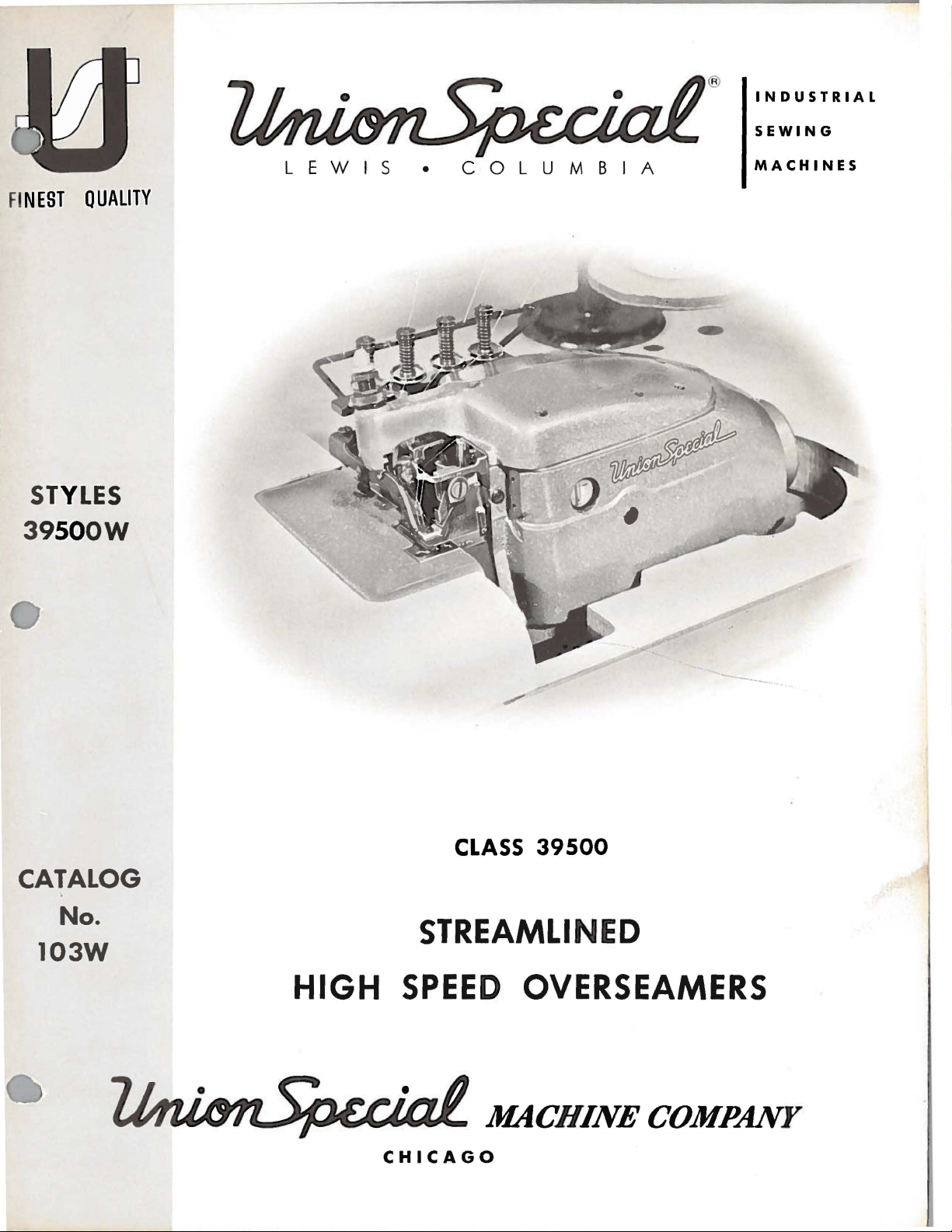
Union Special 39500W User Manual
®
INDUSTRIAL
SEWING
F
INEST
STYLES
3
9500W
QUALITY
LEWIS
•
COLUMBIA
MACHINES
CLASS
CATALOG
39500
No.
STREAMLINED
103W
HIGH
SPEED
CHICAGO
OVERSEAMERS
MACHINE
COMPANY
Catalug
No
.
103
W
I~STRU
ADJUSTI~G
LIST
CL
OF
\SS
Style
3 9
C
TIONS
FOH
.t\~D
39500
500
P A
w
OPER
HTS
A
TI
N G
Un'on
Rights
First
Copyri
Special
Reserv
Edition
g
by
e d
ht
M
in
1958
achi
A
ll
MACHINE COMPANY
INDUSTRIAL
Printed
SEWING
CHICAGO
in
MACHINES
U.S.
ne
Co.
Countri
A.
e s
July,
1971
IDENTIFICATION
OF
MACHINE
Each
plate
Style
on
numbers
Example:
only
minor
ard
Style
Styles
which
contains
This
junction
Styles
39 500
This
herein.
39500.
are
ion
Two
All
taken
of
handwheel
Needle,
Trimming
System.
Union
the
machine.
have
"Style
changes
number.
of
machines
no
catalog
therewith.
A, B or P are
catalog
It
can
also
references
from
the
Two
Mechanism
Special
39500
Style
one
are
machine
numbers
or
more
W".
made
Example:
similar
letters.
Example:
APPLICATION
is a supplement
Only
those
illustrated
applies
be
specifically
applied
to
directions,
operator's
is
away
Looper,
from
Four
with
carries a Style
are
letters
Special
Style
in a standard
"Style
39500
in
construction
"Class
to
Catalog
parts
with
which
discretion
such
position
while
operator.
STYLES
Thread,
Spring
Pressed
classified
suffixed,
numbers
machine, a "Z"
WZ".
39500
OF
No. 103 S
are
and
listed
to
the
standard
as
seated
OF
MACHINES
Overseaming
Lower
number
as
standard
but
which
never
contain
are
grouped
".
CATALOG
used
at
the
on
back
Styles
to
some
right
at
and
the
Machine.
Knife,
is
stamped
and
contain
the
is
suffixed
under a Class
and
should
Style
39500
of
the
of
machines
special
left,
front
machine.
Automatic
in
special.
the
letter
letter
be
to
used
W
"Z".
the
and
book.
machines
and
back,
Operating
Differential
Lubricating
the
name
Standard
"Z".
When
stand-
number,
in
con-
not
on
as
listed
in
Class
etc.,
direct-
Feed,
39500
stitch.
wear,
left
inch.
CAUTION!
filled
straight
should
Machine
gauge
when
machine
Machine
main
reservoir
Drain
a
magnetic
have
entered
W
For
ladiee.'
needle
before
mineral
be
used.
on
front
plug
seaming
For
operations
undergarments,
17/64
Oil
beginning
oil
is
filled
of
machine.
is
stationary.
is
automatically
filled.
screw
screw
the
designed
crank
light
to
on
inch,
was
stitch
drained
to
operate.
of a Saybolt
with
oil
at
Red
lubricated.
Check
is
oil
located
to
case.
It
heavy
knitted
pajamas,
and
range 6 to
OILING
from
Oil
viscosity
spring
tip
of
oil
daily
at
before
back
accumulate
should
NEEDLES
and
bathing
similar
machine
capacity
of
cap
in
top
indicator
No
oiling
the
of
machine
possible
be
removed
woven
suits,
articles,
20
per
when
of
90
to
cover.
should
is
morning
and
fabrics
house
standard
inch,
shipped,
Class
125
seconds
Oil
necessary,
start;
near
bottom
foreign
cleaned
with a modified
dresses,
width
standard
so
reservoir
39500
level
show
is
at
100°
is
checked
between
other
add
oil
edge
materials
periodically.
children's
of
seam
setting
six
ounces.
Fahrenheit
gauge
than
as
required.
of
base.
which
safety
from
10
per
must
at
be
sight
lines
keeping
It
is
may
A
Each
notes
number,
in
thousandths
size
number
packaged
the
stamped
and
Union
kind
represent
sold
Special
of
shank,
on
of
an
by
needle
the
needle
inch,
the
Union
has
point,
shank,
midway
complete
Special.
both
length,
between
symbol
type
and
groove,
denotes
which
3
size
finish
largest
shank
is
and
given
number.
and
other
diameter
eye.
Collectively,
on
the
The
of
label
type
details.
blade,
of
number
The
measured
type
all
needles
de-
size
and
NEEDLES
(Continued)
Style
Type
long
032,
154
tapered
036,
To
sample
on
label.
Selection
should
Success
of
needles
putation
more
than
Release
Fig.
1) .
direction
wrench
turn.
Again
39500 W uses
GAS.
It
point,
040, 044,
have
needle
needle,
A
complete
of
pass
freely
in
the
packaged
for
producing
three-quarters
pressure
and
swing
until
No.
needles
21388
turn
curved
is a curved
struck
049, 054,
orders
or
the
type
order
proper
through
operation
under
highest
on
presser
are
AU,
furnished
handwheel
blade
blade,
groove,
060.
promptly
and
size
would
needle
size
needle
of
Union
our
brand
quality
of a century.
CHANGING
presser
arm
(H)
at
their
with
until
needles
needles.
standard
chromium
and
number
read:
is
determined
eye
in
Special
name,~
needles
foot
by
out
lowest
machine,
are
The
length,
plated
accurately
should
"1000
order
Needles,
to
machines
NEEDLES
turning
of
pos:l.tion.
point
at
their
standard
single
in
sizes
filled,
be
forwarded.
Type
by
size
of
produce a good
can
;
which
in
materials
presser
foot
Turn
of
travel.
loosen
high
Using
needle
position;
needle
groove,
an
thread
be
for
shallow
022, 025,
empty
Use
154
GAS,
used.
stitch
secured
is
backed
this
027,
package,
description
Size
formation.
only
and· workmanship
release
handwheel
bushing
in
operating
hexagonal
clamp
nut
about
withdraw
style
spot,
029,
036".
Thread
by
use
by a re-
for
(S,
socket
1/4
needles.
is
a
To
the
left,
rest
is
against
again
position;
After
up
through
able
thread
Then
thread
thread
guide
thread
guide
Only
Parts
It
are
will
threading
Before
direction
turning
replace
insert
stop
at
its
re-lock
threads
back
guide.
wire
parts
placed
simplify
lower
beginning
until
presser
needles,
needles
pin.
low
point
presser
come
eyelets,
Next,
(A),
continues
(B).
involved
in
their
looper
needles
foot
leave
in
Keeping
of
foot
from
then
they
down
between
in
relative
threading
first,
to
thread,
(L)
are
release
needle
holder,
needles
travel;
release
cones
down
are
through
tension
threading
this
upper
swing
at
high
bushing
holder
one
on
each
in
this
then
tighten
bushing
THREAD
on
through
STAND
thread
front
threaded
right
hand
discs
THREADING
are
positions
for
machine
looper
cloth
second
plate
position,
(S);
and
at
high
side
position,
nut.
(S).
stand
eyelets
through
hole
(U),
shown
clarity.
to
follow
and
open,
release
swing
position
of
turn
Return
(Z,
(Y)
each
and
through
in
threading
recommended
needles
turn
pressure
presser
and,
spacer
handwheel
Fig.
and
pair
up
throu
slot
third.
handwheel
arm
with
washer,
presser
1),
they are
throu
of
holes
gh
(T),
diagram
on
presser
(H)
the
until
until
arm
brought
gh
the
in
left hand
and
on
through
(Fig.
sequence
in
operatin
out
of
position.
flats
to
they
holder
(H)
to
adjusttension
hole.
1).
of
foot
by
g
Be
tension
sure
discs
threads,
(U)
and
as
in
diagonal
they
come
slots
from
(T)
4
the
in
tension
tension
posts
thread
(V).
guide,
are
between
tJ
Tcn
sto
n ' ul
riTcns ion
m
J'
em.Hon Pust
~~~T
e nsion
'l e
ns
ion Pos
Sl
D
ut
Spr·inJ.:
D t
scs
t
m
Thre.1d
G td ·
(~Uppe
m ,
II
II
r
Loopet· Thre
\L
LXili.try Loop
Lower
Looper
F.,hrrc Gua r·d Bt
er
Thr
Figure
·ac
.td Eyt
Thre
eucl
kel
1
•let
ad
Ey<'ll'l
Ey<'i<'l
Uppe
r· L
uopPr
l'
hrP
acl
Tube .\ssem
Lowe r Loupe •·
hl
5
 Loading...