

Page 1
LEWI
S •
SEWING
MA
CHI
NES
NEST
QUALITY
STYLES
39500S
39500T
39500U
.
CLASS 39 500
No.
STREAMLINED
103U
Second
Edition
HIGH
SPEED
OVERSEAMERS
Page 2

Page 3
Catalog
INSTRUCTIONS
FOR
No.
103
U
39500
furnished
ADJUSTING
LIST
s
The
parts
at
list
CLASS
39500
listed
prices
Second
AND
OF
Styles
Edition
OPERATING
PARTS
39500
T
in
this
for
39500
catalog
repairs
u
are
only.
Union
Rights
MACHI
INDUSTRIAL
Copyright
Special
Reserved
NE
CHIC A
Printed
by
COMPANY
SEWING
in
1958
Machine
in
All
MACHINES
GO
U.S.A.
Countries
Co.
November,
1967
Page 4

Page 5
FOREWORD
The
streamlined
performance
precision
It
enable
Specials.
and
Union
anxious
Class
is
our
the
illustrate
to
39500
styling,
are
methods
constant
customer
The
following
and
Special
cooperate
machine
automatic
characteristics
insuring
aim
to
describe
representatives
with
complete
to
secure
pages
the
you
furnish
is
lubrication,
of
all
possible
contain
parts
will
to
plan
Union
these
interchangeability.
carefully
for
and
Special's
machines.
advantages
valuable
Styles
be
found
estimate
and
prepared
operating
in
in
~
latest
light
All
Class
all
manufacturing
requirements.
overedger.
running
parts
information
from
and
39500.
New
high
are
the
use
adjusting
MACHINECOMPANY
speed
made
that
will
of
Union
data,
centers,
by
3
Engineering
Department
Page 6
IDENTIFICATION
OF
MACHINES
Each
plate
Standard
the
letter
letter
is
suffixed
Styles
ber,
This
herein.
Class
back,
Operating
Single
chine.
Pressed
Union
on
the
Style
"Z".
"Z".
of
which
catalog
It
39500.
etc. , are
direction
Curved
Intermittent
Lower
39500 S For
materials.
Knee
foot
on
press
to
separate
stitch
Special
machine.
numbers
Example:
When
to
the
machines
contains
applies
can
also
All
taken
Blade
Knife,
seaming
Seam
controlled
length.
carries
Style
only
minor
standard
similar
no
letters.
APPLICATION
specifically
be
applied
references
from
of
handwheel
Needle,
Differential
Automatic
and
specification
top
and
a
Style
numbers
have
one
"Style
or
39500
changes
Style
numbe:r.
in
construction
Example:
to
with
to
directions,
the
operator' s position
is
STYLES
Two
OF
Looper,
Feed
Lubricating
intermittently
504-SSa-1.
tandem
bottom
intermittent
plies.
number
are
classified
more
letters
S".
aremade
Example: "Style
"Class
OF
the
standard
discretion
away
from
MACHINES
,
Trimming
gathering
Gathering
which
suffixed,
Special
Style
in a standardmachine,
are
grouped
39500
CATALOG
Styles
to
some
such
as
while
operator.
Three
Thread,
System.
on
knit
Standard
differential
ratio
is
stamped
as
standard
but
numbers
39500
under a Class
11
•
of
machines
special
right
and
seated
Overseamin
Mechanism
or
light
width
of
feed.
up
to 3 to 1 depending
in
the
and
special.
never
contain
contain the
SZ".
as
listed
machines
left, front
at
the
machine
g
with
weight
seam
Spring
woven
1/8
Slotted pres
nam
a
"Z"
num-
and
Ma-
inch
ser
e
in
.
.
39500
T
For
rial.
Knee
press
bottom
plate
39500
attachment.
U
For
rial.
Knee
press
bottom
plate
attachment.
CAUTION!
must
ounces.
1
00°
Fahrenheit
be
filled
A
Machine
at sig
ht
ga uge
between gau
seaming
Seam
specification
controll
grooved
seaming and
Seam
specification
controll
groov
ed
Oil was
before beg
straight
should
is
filled
on front
ge lines.
and
ed
tandem
for
1/8
inch
Gathe
ed ta
for
1 I 8 inch
Gathering
dr ained
inning
m i ner al o
be
with
oil
of
machine.
intermittently
504-SSa-1.
intermittent
cord. Independent
ring
ratio
intermittently
504-SSa-1.
ndem
intermittent
cord.
Independent
ratio
OILING
from
to
operate.
il
of a Saybolt
used.
at spring cap
Red
gathering
Standard
primarily
width
differential fee
swing-out
up
to 3 to
gathering
Standard
1 depe
primarily
width
differenti
ndi
al
swing-out aux
up
to 5 to 1 depending on
machine
in
bulb
wh
Oil
capacity
viscosity
top
cover.
on
oil
level
en s
of
hipped,
of
200
indicator
on
of
seam
d.
auxiliary
ng
on
on
of seam
feed.
iliary pres
Clas
s 395
to
250 s e
Oil
level
woven
Pr
sti
wov
mate-
3/16
inch.
esser foot
pr
es s
ure
tch
leng
th.
en m at e -
3/16
inch.
Presser foot
sure
stitch
s o r e s e
should
00
conds
is
checked
length.
rvoir
is
six
at
show
4
Page 7
THREAD
STAND
Afterthread
through
is
threaded
right
hand
tension
Only
Parts
It
are
will
threading
Before
ating
foot
of
direction
by
position.
Be
sure
tension
Double
eyelet
thread
of
heel
from
are
(E,
pull-off
frame
of
left
in
left
back
through
hole
discs
parts
placed
simplify
lower
beginning
turning
threads.
discs
end
Fig.
looper
lower
to
right.
hand.
comes
thread
and
(AD).
involved
in
looper
until
presser
(AD)
of
thread
1)
from
(T).
thread
looper
from
eyelet.
each
up
pair
through
through
in
their
relative
threading
first.
to
thread.
needle
foot
as
they
and
in
diagonal
TO
and
right
Lead
thread
guide
(K)
is
Left
eye
cone
then
down
of
holes
left
slot
THREADING
threading
this
machine
upper
swing
(N)
is
at
release
come
THREAD
lead
to
left.
behind
(G).
all
the
way
of
lower
on
thread
through
in
hand
hole.
(AE).
are
shown
positions
looper
cloth
high
position.
bushing
from
slots
the
(AE)
LOWER
it
through
Note:thread
fabric
Turn
handwheel
to
the
looper
stand
front
tension
Then
and
on
for
to
follow
second.
plate
( U);
tension
in
LOOPER
both
guard
left;
can
(V.
thread
thread
thread
through
in
threading
clarity.
recommended
and
open.
turn
release
and
swing
thread
tension
eyes
must
(F)
in
operating
then
thread
be
threaded
Fig.
guide
needle
pressure
posts
of
pass
and
presser
lower
1).
it
is
brought
eyelet
(W).
wire
continues
thread
guide
diagram
sequence
third.
handwheel
on
arm
guide,
are
(AC).
looper
in
front
through
direction
through
easily
if
Next
(A).
down
between
(Fig.
in
oper-
presser
(H)
between
thread
of
looper
both
holes
until
both
eyes
tweezers
up
it
(B).
1).
of
out
Turn
thread
through
through
both
threadmust
looper
and
push
thread
down
tube
CAUTION!
passing
from
Turn
highest
needle
hole
knurled
to
secure
in
The
position.
thread
top
amount
tension
handwheel
auxiliary
eyes
pass
in
tube
through
down,
then
Be
tube
handwheel
Insert
eyelet
cover
needle
of
nuts
proper
stitch
TO
until
of
upper
front
assembly
thread
insert
sure
upper
assembly
TO
in
operating
needle
(R),
thread
tension
(AA.
formation.
THREAD
point
looper
looper
of
looper
(M).
tube
assembly
thread
looper
to
upper
THREAD
thread
under
eyelet
THREAD
on
needle
Fig.
1).
UPPER
of
upper
thread
thread
thread
lead
through
thread
looper
direction
neck
of
and
Tension
LOOPER
looper
eyelet
eyelet
pull-off
thread
(M).
upper
is
eye.
THE
NEEDLE
until
from
(P).
top
right
cover
Thread
TENSION
looper
on
7
(L)
(D)
(C)
under
Pull
looper
under
needle
to
casting;
threads
threads
is
from
from
(T).
neck
thread
eye
lower
left.
needle
all
the
back
left
After
of
out
from
looper
(N.
through
then
from
is
should
way
left.
to
front,
to
right.
pulling
top
cover
bottom
front
thread
Fig.
1)
both
down
front.
regulated
be
only
Lead
then
Note:
up
upper
casting
of
tube;
to
back.
when
is
at
eyes
through
by
three
enough
its
of
Page 8
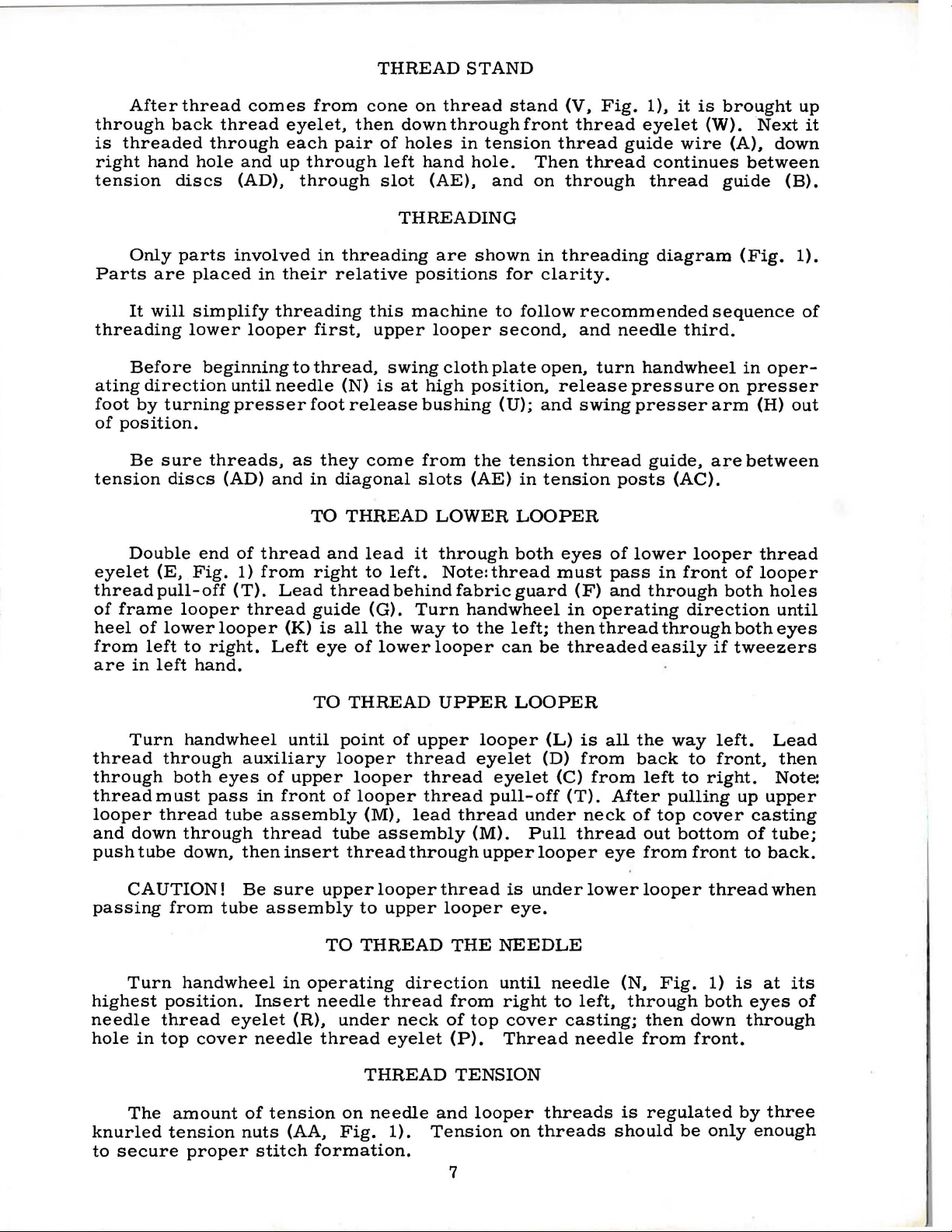
Suffi
be
maintained.
de
crea
s e
lock
nul
Adjusting
increases
When
pressure
set, lig
on
throat
under
from
(D) ug·
surface
the
1insl
P
,ESSER
ci e
nt
pressure
Should
amount
(A, Fig . 2)
s c
rew
has a right
pressure,
adjusting screw
hten
lock
plate,
is
approximately
lop
surfa
locking nut
FOOT
to
il
be
of
pressure
and
loosening dec
nul
(i\).
position
ce
of
adjusting screw
(C).
PRESSURE
feed
necessary
on
turn
hand
Wilh
locking
FEED
work
uniformly
presser
adjusting
thread;
reases
(B)
has been
presser
nut
1 I
32
inch
ECCENTRICS
lo
so
(C)
(B).
should
increase
foot,
loosen
screw
tightening
pressure.
properly
fo
ot
resting
so
that
to
1 I
16
Set
or
(B).
its
inch
cap
Fig.
2
Feed
approximately
main
is
No.
numbers
obtainable
mately
shipped
Generally
ber
of
so
as
Following
5,
6,
36,
eccentrics
with a minor number
"39540-12".
is
also
Defore
uard, upper
g
sugge
feed
39540-4
3 1 I 3
stitches
to
7,
40.
available
sted
eccentri
e c
of
the
when
with
give
8,
9,
Only
may
asse
sequence:
14
stitches
entric
for
part
using
stitches
above
speaking,
produced;
the
proper
stitch
10,
two
be
No.
for 5 to 1 ratio
ASSEMBLING
mbling
knife
s
us
d i n
per
is
No.
Styles
combinations
11, 12, 13,
ordered
39540
39500
symbols
that
eccentric.
per
inch.
the
the
differential
number
eccentrics
suffixed
A,
sewing
assembly,
main
feed
separately.
producing approximately
these
39540-14
different'al
to
AND
machines
inch.
S, T and
indicate
Unless
of
eccentrics
(right
or gathering
eccentrics
14,
15,
are
supplied
indicate
differential
ADJUSTING
parts,
lower
It
knife
have
will
be
noted
while
No.
remove
that
No.
39540 A for
approximately
39540 A eccentric
otherwise
.
hand)
16,
number
(left
18,
To
feed
hand)
are
available
20,
with
order
of
feed mac
SEWING
cloth
holder
been
of differential
specified,
eccentric
action.
22,
each
an
stitch
assembly; then follow this
selected
that
the
Style
the
number
feed
eccentric
under
24, 26, 28,
machine.
eccentric,
es
desired.
3 1 I 3
hines.
PARTS
plate,
fabric guard, chip
to
part
feed
39500
of
produces
machines
determines
is
No.
30, 32, 34,
use
stitches
produce
number
eccentric
U.
Minor
stitches
approxi-
will
num-
selected
39540-
Additional
No.
39540
Example:
per
of
be
4,
inch
Fi
g . 3
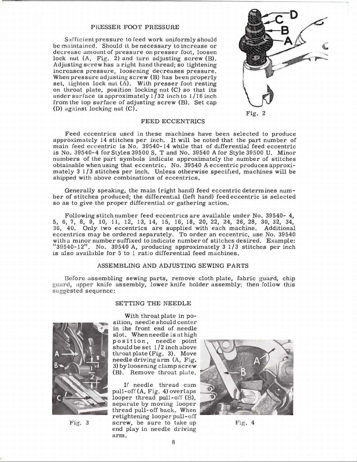
SETTING
With
sition,
in the
slot.
position,
should
throat
needle
3)
by
loosening
(B).
If
pull-off(A,
looper
separate
thread
retighten
screw,
end play
arm.
THE
throat
need
front
When
be
set
plate
driving
Remove
needle
F i
thread
by
pull-off
ing
be
sure
in
NEEDLE
plate
in
po-
le
should
end
needle
needle
112
(Fig.
arm
clamp
throat plat
thread
g.
pull-o
mov
loop
needle driving
of
is
inch
3).
(A, F i
4)
overlaps
ing loo
bac
k. W
er
pull-o
to
8
center
needle
at
high
point
above
Move
screw
cam
ff (B),
take
per
hen
g.
e.
ff
up
Fig. 4
Page 9
SETTING
sert
Fig.
With
left
set
inch
needle
looper
21225-118.
have
flecting
Tighten
THE
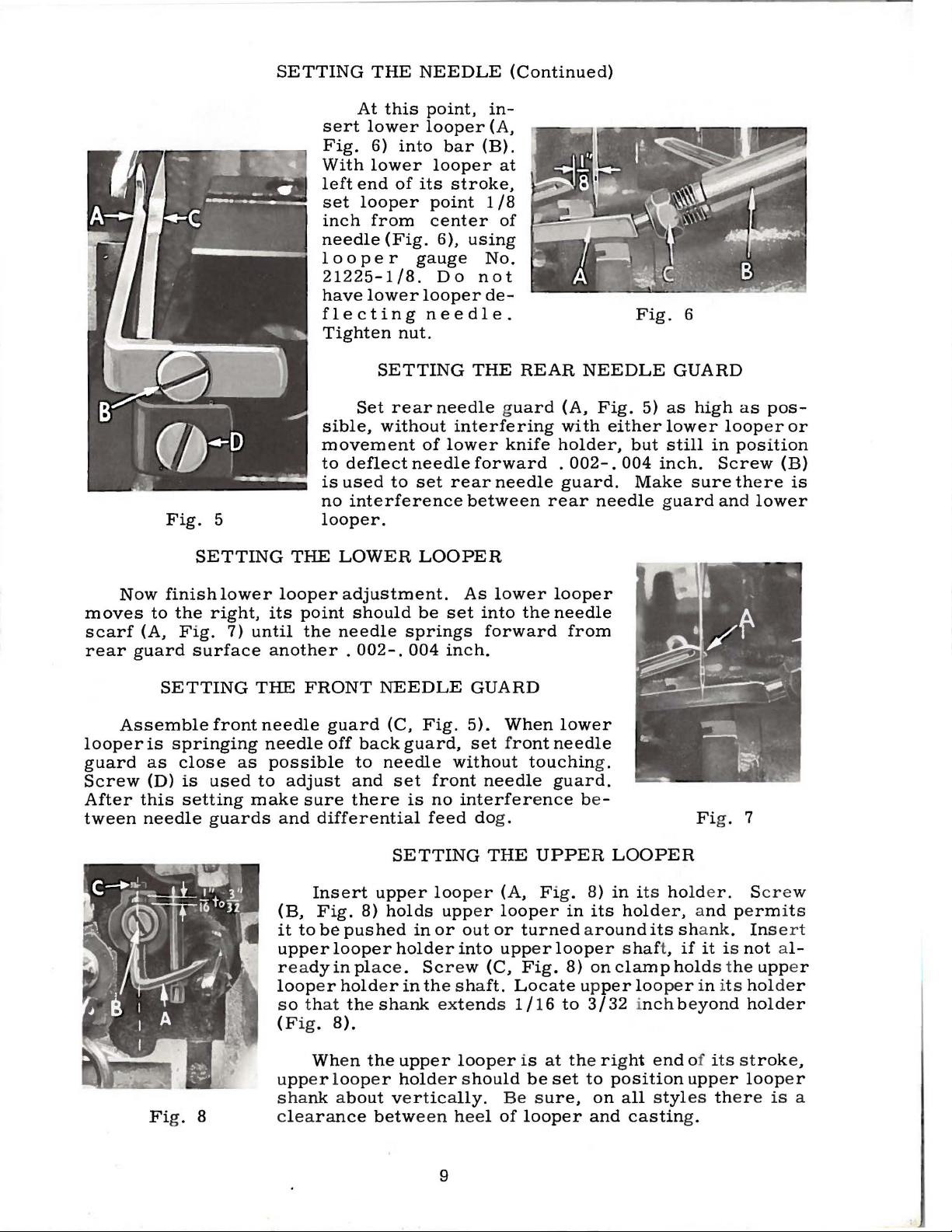
At
this
NEEDLE
point,
lowerlooper(A,
6)
into
bar
lower
end
looper
from
(Fig.
of
looper
its
stroke,
point
center
6),
gauge
Do
lower
looper
needle.
nut.
(Continued)
in-
(B).
at
1
18
of
using
No.
not
de-
Fig.
6
Now
moves
scarf
rear
Assemble
looper
guard
Screw
After
tween
Fig.
finish
to
the
(A,
Fig.
guard
SETTING
is
springing
as
close
(D)
this
needle
5
SETTING
lower
right,
7)
surface
front
as
is
used
setting
guards
THE
looper
its
until
another
THE
needle
needle
possible
to
adjust
make
and
Set
sible,
movement
to
deflect
is
used
no
interference
looper.
LOWER
adjustment.
point
the
should
needle
.
002-.
FRONT
guard
off
back
to
and
sure
there
differential
SETTING
rearneedle
without
of
lower
needle
to
set
LOOPER
be
set
springs
004
inch.
NEEDLE
(C,
Fig.
guard,
needle
set
front
is
no
feed dog.
THE
REAR
g
uard
interfering
knife
forward
rear
needle
between
As
lower
into
the
forward
GUARD
5).
When
set front
without
touchin
needle
interference
NEEDLE
(A,
with
holder,
.
002-.
guard.
rear
looper
needle
from
lower
needle
guard.
be -
Fig.
either
but
004
Make
needle
g.
5)
inch.
as
lower
still
guard
GUARD
high
looper
in
Screw
sure
and
Fi
g. 7
as
pos-
or
position
(B)
there
is
lower
Fi
g. 8
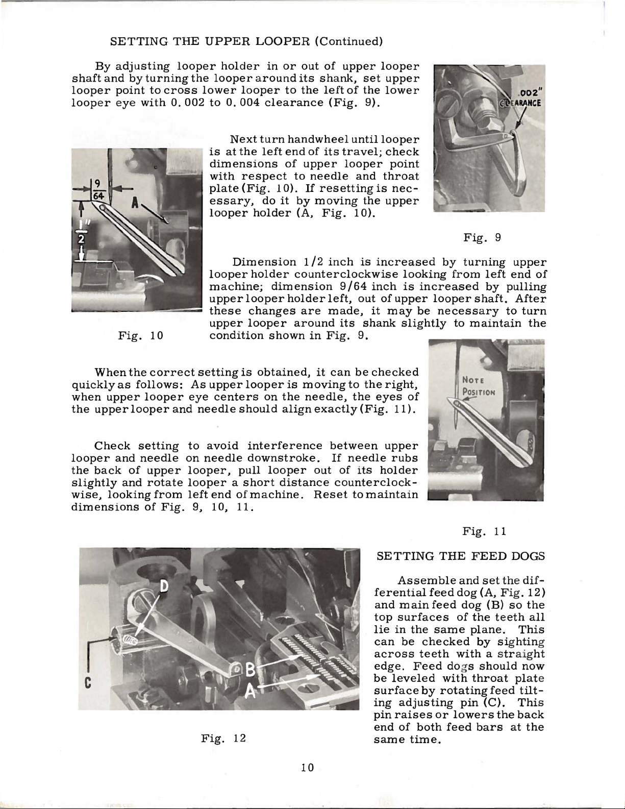
SETTING
Insert
(B,
it
to
upper
Fig.
be
upper
8)
pushed
looper
holds
in
holder
readyin place .
loop
er
hold
er
in the s ha
at the sha
s o th
(Fig.
u
sha
8).
Wh
en
pp
er l
oop
nk about vertically.
clearance
the
er
betw
nk exte
upper
hold
loop
or
Scr
er s
een heel of
9
upp
into
ew
loop
THE
er
er
out
(C,
ft.
nd
hould
UPPER
(A,
Fi
g. 8)
looper
or
turned around
upp
er
looper shaft,
Fig.
Locate upper
s 1 I 16
er is
to
at the rig
be
set
Be sure,
looper
in
8)
LOOPER
in its holde
its
holder, and perm
its shank. Inse
if
on
clamp
hold
looper in it s holde
3 I 32 i
to
on
and
nc
h beyond holde r
ht
end
position
all styl
castin
of
upp
es ther e
g.
r. Scre
it
is
not al-
s the
its strok
er
loop
upp
is
w
it s
r t
er
r
e,
er
a
Page 10
By
shaft
and
looper
loop
er eye with
SETTING
adjusting
by
turning
point
to
THE
looper
cross
0.
002
UPPER
holder
the
looper
lower
to
0.
is
at
dimensions
with
plate
essary,
looper
LOOPER
in
around
looper
004
clearance
Next
turn
the
left
respect
(Fig. 1 0).
do
holder
(Continued)
or
out
its
shank,
to
the
handwheel
end
of
of
upper
to
needle
If
resetting
it
by
moving
(A,
Fig.
of
left
(Fig.
its
upper
set
of
the
9).
until
travel;
looper
and
the
10).
looper
upper
lower
looper
check
point
throat
is
nec-
upper
Fig.
When
quickly
when
the
as
upper
upperlooperand
Check
looper
the
slightly
wise,
and
back
and
looking
dimensions
10
the
correct
follows:
looper
setting
needle
of
upper
rotate
from
of
looper
machine;
upper
these
upper
condition
setting
As
upper
eye
needleshould
to
avoid
on
needle
looper,
looper a short
left
end
Fig.
9,
Dimension
is
centers
pull
ofmachine.
10,
11.
holder
looper
counterclockwise
dim
ens
holder
changes
looper
around
shown
obtained,
looper
on
is
the
alignexactly(Fig.
interference
downstroke.
looper
distance
1/2
inch
ion
left,
are
made,
in
Fig.
it
can
moving
needle,
between
If
out
Reset
is
increased
9 I
64
inch
out
of
upper
it
may
its
shank
9.
be
checked
to
the
right,
the
eyes
11).
upper
needle
of
its
rubs
holder
counterclock-
to
maintain
looking
is
increased
looper
be
slightly
of
Fig.
by
turning
from
shaft.
necessary
to
maintain
Fig.
9
left
by
11
upper
end
of
pulling
After
to
turn
the
Fig.
12
10
SETTING
Assemble
ferential
and
main
top
surfaces
lie
in
the
can
be
across
edge.
be
Feed dogs
leveled
surface
ing
adjusting
pin
raises
end
of
both
same
time.
THE
feed
feed
same
checked
teeth
with
by
rotating
or
feed
FEED
and
set the dif-
dog
(A,
dog
of
the teeth
plane.
by sig
with
should
throat
pin
lowers
bars
DOGS
Fig.
12)
(B)
so
the
all
Th
is
htin
a straight
now
plat
feed
tilt-
(C).
the
Thi
back
at
the
g
e
s
Page 11
The
the
throat
feed
dogs
ferential
feed
plate.
so
feed
dogs
that
may
SETTING
should
Screw
teeth
be
(D)
rise
set
THE
be
set
locks
about
slightly
FEED
level
feed
3/64
higher
DOGS
at
the
tilting
inch
if
(Continued)
time
adjusting
above
desired.
the
the
teeth
pin
throat
first
in
place.
plate.
appear
The
above
Now
set
dif-
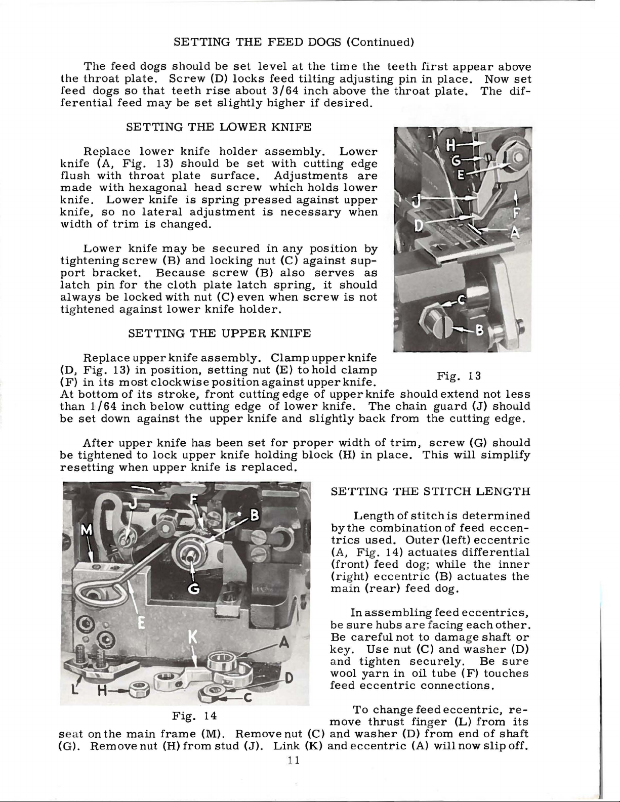
Replace
knife
flush
made
knife.
knife,
width
(A,
with
with
Lower
so
of
Lower
tightening
port
latch
always
bracket.
pin
be
tightened
Replace
(D,
Fig.
(F)
in
its
At
bottom
than
1/64
be
set
down
SETTING
lower
Fig.
throat
hexagonal
no
lateral
trim
is
knife
screw
for
the
locked
against
SETTING
upper
13)
in
most
of
its
inch
against
THE
knife
13)
should
plate
knife
is
adjustment
changed.
may
be
(B)
and
Because
cloth
with
lower
THE
knife
position,
clockwise
stroke,
below
cutting
the
LOWER
holder
be
surface.
head
screw
spring
secured
locking
screw
plate
nut
(C)
knife
UPPER
assembly.
setting
position
front
upper
set
pressed
nut
(B)
latch
even
holder.
nut
cutting
edge
knife
KNIFE
assembly.
with
cutting
Adjustments
which
holds
against
is
necessary
in
any
(C)
against
also
spring,
when
screw
KNIFE
Clamp
(E)
to
against
upper
edge
of
lower
and
slightly
Lower
lower
upper
position
serves
it
should
is
upper
hold
clamp
knife.
of
upper
knife.
edge
are
when
by
sup-
as
not
knife
knife
The
back
should
chain
from
Fig.
extend
guard
the
13
(J)
cutting
not
less
should
edge.
After
be
tightened
resetting
seat
on
(G).
Remove
the
upper
to
when
main
nut
knife
lock
upper
Fig.
frame
(H)
has
upper
knife
14
(M).
from
been
knife
is
stud
set
for
holding
replaced.
Remove
(J).
nut
Link
11
proper
block
(C)
(K)
width
(H)
SETTING
in
of
trim,
place.
THE
Length
by
the
combination
trics
(A, Fig .
(front)
(right)
main
be
Be
key.
and
wool
feed
move
and
used.
feed
eccentric
(rear)
In
assembling
sure
hubs
careful
Use
tighten
yarn
eccentric
To
change
thrust
washer
14)
and eccentric
screw
This
STITCH
of
stitch
Outer
actuates
dog; while
(B)
feed
dog.
feed
are
faci
not
to
dama
nut
(C)
securely.
in
oil
tube
connections.
feed
finger
(D)
from
(A)
will
(G)
should
will
simplify
LENGTH
is
determined
of
feed
eccen-
(left)
eccentric
differential
the
inner
actuates
the
eccentrics,
ng
each
other.
ge
shaft
or
and washe r (D)
Be
sure
(F)
touches
eccentric,
(L) from
end
now
of
slip
re-
its
shaft
off.
Page 12

SETTING
THE
STITCH
LENGTH
(Continued)
Using
eccentric
handwheel
shirring
so
for
The
For
the
upper
hooked
intermittent
adjusting
eccentric
(B)
as
shown
back
micrometer
operations
position.
Fig.
and
15
screw
extractor
and
forth
where
slightly
adjusting
various
operations,
stop
withdraw
during
ential
the
lever
top
Amount
and
near
(moving
action.
reverse.
screw
sizes
it
may
(B)
is
for
(E),
supplied
eccentric.
extraction.
SETTING
Differential,
feed
micrometer
The
(A)
stop
(C)
determines
Rotation
tension
top
A
for
the
are
be
advantageous
lower
with
It
THE
action
position
is
governed
(B)
and
of
movement
ofadjustingthumbscrew
stop
counterclockwise
top
stop
encountered.
stop,
and
machine,
may
be
DIFFERENTIAL
plain,
is
obtainable
adjusting
of
the
by
the
lower
by
feed
action.
post
down)
assembly)
increases
is
ideal
to
the
stationary
reach
necessary
or
reverse
thru
screw
differential
two
settings--the
stop
lever
reverse
screw
between
differential
turn
for
the
behind
to
move
RATIO
differ-
use
of
(Fig.
clockwise
continuous
stop
15).
control
(C).
(located
acts
stops--
(C)
(B)
the
is
The 3 to 1 ratio
differential
maximum
Assemble
presser
can
be
Foot
collar
arm
does
release
foot
and
plate
screw.
Adjust
presser
looper
this
maximum
so
point
foot
tongue.
the
presserfoottreadle
toe
of
the
upper
lever
locked
before
differential,
arm
realigned
lifter
(B)
secure
not
bushing
stitch
needle
lifter
foot
will
of
upper
foot.
looper.
with
feed
presser
into
lever
bind
is
tongue
hole,
can
be
permit,
safe
looper
Raise
Height
presser
nut
(F).
machines
dogs
unlocked.
lever
There
from
and
foot
sewing
with
arm
the
shaft.
and
rise
with
loosen
stop
raised
then,
position,
is
presser
and
adjustment
foot
are
striking
screw
SETTING
to
position
throat
(A,
when
To
respect
presser
screw
no
higher
lock
turn
directly
foot
manuallylowerthe
should
begins
should
THE
presser
and
plate
Fig.
Be
sure
presser
center
nut
(D).
the
over
by
is
correct
be
from
to
rise.
(C)
depressing
equipped
the
throat
not
PRESSER
arm.
lock
in
slots
16)
and
presser
foot
presser
to
throat
foot
hinge
so
that
than
upper
To
find
handwheel
presser
if
1/16
This
with a stop
plate
be
removed.
FOOT
With
by
presser
to
adjustment
place.
shifting
1/8
needle
inch
screw
when a machine
in
high
If
necessary,
foot
lifter
Fig.
foot
tongue
free
is
made
does
motion
with
(D)
to
position,
presser
lever
16
not
of
foot
screw
prevent
is
set
swing
foot
shaft.
contact
lifter
(E),
at
Finally,
re-assemble
chip
guard,
fabric
guard,
12
cloth
plate.
Page 13

SETTING
THE
AUXILIARY
PRESSURE
PLATE
Styles
(Fig.
17)
To
this
assembly,
follows:
1.
Swing
position
hinges
Adjustment
screw
2.
Set
(C)
parallel
main
in
(B,
39500
which
check
it
freely
the
so
shaft
either
Fig.
T,
operates
the
operation
proceed
out
of
and
on
is
(A)
and
adjusting
that
to
the
of
shaft
the
direction
18).
U
are
operating
see
that
its
made
nut
screw
(D)
axis
machine.
equipped
in
of
as
it
pivot.
by
(B).
is
of
the
Fig.
about
with
conjunction
18
180°
from
an
auxiliary
with
the
operating
pressure
presser
Fig.
3.
position
foot.
17
Adjust
erally
sure
plate
centrally
ferential
Loosen
B,
Fig.
Making
will
release
tension
plate.
tension,
sure
the
plate
shaft
and
plate
the
so
that
screws
18)
this
on
To
swing
tighten
assembly
shaft
(D)
the
(E)
locates
over
the
feed
to
do
adjustment
the
the
pressure
re-gain
the
out
and
(D,
Fig.
lat-
pres-
dif-
dog
(A
and
this.
spring
the
pres-
turn
17)
screw
.
4.
With
the
the
pressure
the
spring
operating
loosen
5.
With
the
mountingbracket
with
feed
6.
Adjust
parallel
end
of
the
top
7.
There
used
fo·r
8.
A
chain
with
the
to
the
pressed.
normally
differential
plate
will
lever
screw
(A,
differential
dog
teeth.
the
pressure
with
the
plate
ply
are
and
being
two
increasing
is
provided
presser
presser
the
presser
attached
resting
allow,
(F,
Fig.
Fig.
(C,
feed
presser
sewn.
spring
or
foot.
foot
to
feed
dog
there
17)
18)
feed
dog
Fig.
plate
dog,
foot
Use
anchoring
decreasing
for
raising
Couple
lifter
chain
foot
the
operating
down
on
should
and
and
at
18)
in
so
to
the
this
raises
the
the
move
its
below
throat
be
hinge
highest
the
plate
about
block
lever
surface
1/32
to
point
with
the
inch
(G).
To
desired
of
travel,
of
the
maximum
clearance
make
position.
sothattheauxiliarypressureplateisparallel
or
out
that
permit
two
the
towards
there
screws
holes
spring
auxiliary
chain
so
that
before
lever
is
free
in
tension
from
when
presser
sufficient
passage
(D,
Fig.
collar
pressure
the
the
the
pressure
at
the
clearance
of
18)
(E.
Fig.
on
auxiliary
operating
foot
lifter
plate.
inside
hole.
foot,
the
for
plate
13
throat
between
this
raise
or
maintaining
between
thickest
this
adjustment.
18)
which
pressure
in
conjunction
lever
(F,
treadle
The
plate,
and
pressure
the
adjustment
lower
the
the
part
may
be
plate.
Fig.
17)
is
de-
chain
is
it
of
Page 14

Be
With
the
middle
foot
in
presser
sure
thread
place,
foot
machine
tensions
of
their
to
into
is
light,
front
make
position,
threaded
to
back
sure
STARTING
according
set
looper
locations.
that
chain
insert
material,
TO
thread
forms
OPERATE
to
threading
eyelets
Operate
and
moves
and
sew
(C &
machine
off
slowly.
diagram
E)
about
slowly,
the
tongue
(Fig.
1,
horizontal
without
freely.
page
and
presser
Swing
6).
in
While
needle
be
just
if
excessive
position
contacts
It
(toward
With
far
enough
rearward
needle
left
hand
time
lower
While
of
lower
comes
lower
looper
keeping
thread
tight
needle
needle
is
also
the
material
position.
thread
eyelet
sewing
looper
off
upper
the
sewing
is
enough
thread
desireable
operator)
so
thread
cam
looper
thread
thread
same
on
material
drawn
thread
to
is
on
needle
feed
pulled
eyelet
thread.
to
to
delay,
LOWER
under
presser
is a little
Looper
pull-off
approximately
is
at
extreme
on
material,
should
looper.
amount
is
To
on
of
NEEDLE
,
check
down
chain
on
(R,
adjust
slightly,
LOOPER
slack
thread
(S).
Frame
1
check
be
drawn
increase
upper
pull-off
THREAD
off
stitch
the
Fig.
the
foot,
when
pull-off
/8
inch
left
end
drawing
amount
looper,
action.
needle
stroke.
up
stroke.
1)
so
needle
the
THREAD
set
lower
looper
looper
right
of
through
move
CONTROL
thread
At
tongue.
that
thread
tightening
looper
thread
(T)
is
threadguide
of
its
travel.
off
oflooper
the
of
thread
lower
control
top
of
needle
Stitch
With
needle
needle
pull-off
of
CONTROL
thread
pull-off
set
about
lower
looper
tension
drawn
looper
as
tends
thread
the
1/8
(G)
thread
before
through
thread
follows:
stroke,
to
at
cam
eyelet
needle
eyelet
(T)
inch
should
(K)
as
lower
thread
pull
down
bottom
pull-off
well-forward
thread.
(E,
Fig.
reaches
distance
beset
heel
eyelet
follows: A portion
looper
the
tension
eyelet
Usually
should
slightly
of
stroke,
(S)
1)
its
behind
with
at
thread
while
(E)
down,
all
just
back
most
its
the
Before
three
will
tensions
not
During
upper
drawn,
pull-off
Tom
should
slightly
If
it
end play
markedly
needle
looper
upper
reaches
ove
be
raised
more
becom
in needle
proceeding
is highe r over
near
top edge
Th
e needl
ing
be
without
be
pulled
sewn.
causing needle
increas
too
ed
far over
to
give a normal
effect
down
thread
through
looper
its
most
the
purl
more
keep
pull-
off
es
necessary
drive
throat
.
e t h
If
plate
upper
read
In general,
as long as
the
UPPER
to
the
LOOPER
adjust
purl.
stroke,
the
thread
will
rearward
POSITIONING
under
ing
the
same
on
upp
er
to
move
shaft
before
than
loop
er is
tension
lower
thread
required
looper
to
the elasticity
top.
THREAD
upper
appearing
forward
tension.
have
looper
stitch.
stroke
When
almost
position.
the
edge,
both
amount
thread
than
looper
tightenin
recommended
too
low, the
THREAD
TENSIO
is a f
thread tens
be pu
lled
down.
of the
14
CONTROL
thread
eyelet
Moderate
of
looper
thread
normal
all
slack
THE
PURL
looper
of
pull-off.
on
lower
thread
g.
If
thread
thread.
pull-o
upp
er
in (F ig . 1 0), the
purl wil
l f
NS
unction
of needle
ion should
Upp
er
loop
cha
in incr
(C,
change
pull-off
amount
taken
up
eyelets
Usually
ff
(T)
be s
looper
purl will tend
orm nearer
thread a nd m at
be set
er
thread t e ns i
eases, or
Fig.
1)
balance
in
these
(T)
of
looper
as
looper
(C & E,
it
is
better
ure
to
is loca
ted so t ha t
bottom
as high
as possible
until the purl
all
tensions
will
draw
thread
is
thread
Fig
.
1)
to
hav
e
take up all
it
to form
ed
ge .
eria
on should
is
l
Page 15

~~
E F
TO
REMOVE
Fig.
19
CRANKSHAFT
U V T
M
Crankshaft
1.
Drain
cated
edge
2.
Remove
chine.
3.
Remove
and,
tractor,
4.
Remove
5.
Remove
Identify
they
per
6.
Remove
shaft
reached
7.
Remove
at
points
assembling
they
Trade
halves
should
ings.
assembled
which
8.
Loosen
holds
Access
cover.
until
connecting
moval
bearing point
shaft.
re-assembling
above.
9.
Remove
inner
screw
casting.
10.
Loosen
remove
11.
Remove
(N).
12.
Loosen
(R).
13.
Remove
bearing
14.
Crankshaft
can
oil
on
back
of
base.
top
feed
with
key
these
will
places.
screw
split
through
caps
are
marks
of
the
be
Also,
they
clamp
upper
to
Draw
upper
of
Observe
screw(K,
right
is
reached
two
both
screw
two
retaining
be
withdrawn
by
removing
of
and
bottom
eccentric
the
aid
slip
off
(G).
three
counterweights
be
re-assembled
(J)
bearing.
bottom
of
bearings
A,
B,
bearing
in
their
are
caps
on
the
same
screws
in
the
were
nut
knife
clamp
driving
knife
rod
(D)
bearing
(C,
same
cap
crankshaft
screws
halves
(M);
screws
three
screws
may
easier
plug
machine
of
the
counterweights
which
and
original
stamped
and
same
removed.
(A,
nut
driving
drop,
cap
Fig.
as
Fig.
through
(L)
take
(P);
plate
near
covers
nut
(E,
the
eccentric
eccentrics
in
holds
This
of
bed
on
crankshaft
D.
When
caps
both
side
driving
precautions
now
make
trade
of
should
holes
Fig.
is
through
arm
lever
allowing
(E).
This
19)
on
described
19)
which
bearing.
bottom
in
fan
of
cooling
off
remove
(S);
(T).
be
if
screw
bottom
of
ma-
Fig.
(F).
(H).
so
that
the
pro-
crank-
screw
casting.
re-
sure
position.
on
both
marks
the
bear-
be
re-
from
20)
which
arm
(B).
to
the
left
(C)
and
re-
is
crank-
when
in
holds
This
of
bed
collar;
fan.
pulley
removed.
cap
pulley
take
these
lo-
19)
ex-
is
top
at
7
off
steps
15.
If
(V),
an
it
it
(U).
16.
Carefully
foregoing
re-assembly
ing
tion
testing
will
17.
Before
clean
and
bottom
pressed
crankshaft
in
The
spring
drain
fore
leakage.
recommended.
15
are
followed:
necessary
it
should
arbor
must
seats
be
against
exploded
of
various
for
also
re-assembling,
and
gaskets.
cover
oil
casting
wick
against
plug
re-assembling
to
replace
be
pressed
press.
pressed
observing
operations
binds
prove
dry
bearing
and
stands
with a sealing
No. 1 Crane
of
view
top
Before
make
wick
that
bottom
In
replacing
on
ground
crankshaft.
drawings
parts
during
helpful.
and
which
is
it
v e r t i c a
to
Fi
g.
ball
off
shaft
carefully
thrust
reverse
should
thorough
bottom
re-assembling
sure
lubricates
inserted
contacts
cover.
20
simplify
for
and
constant
re-assembly
that
11 y on
Coat
compound
prevent
Lead
bearing
on
bearing
until
washer
of
the
Check-
loca-
1 y
covers
sprin
lef
in
hole
shaft.
its
oil
be-
oil
Seal
is
g
t
Page 16

ILLUSTRATIONS
ORDERING
REP
AIR
PARTS
This
of
various
actual
listing
required
Numbers
position
ordering
Component
indicated
assembly.
40
41
42 97
43
44
45
It
not
listed.
mended,
catalog
sections
position
of
the
in
the
of
that
parts.
by
Example:
29126
22729
39544
39544
22729
will
be
so
has
in
the
parts
particular
in
the
part
Always
parts
indenting
DF
D
s
u
E
noted
The
reason
complete
been
of
with
first
in
in
arranged
the
mechanism
machine.
their
view
column
the
illustration.
use
of
sub-assemblies
their
Lower
Rod
Assembly----------------------------------------Screw,
Screw,
Ball
Lower
Screw,
the
above
is
that
sub-assembly
to
On
the
part
being
are
the
part
descriptions
Looper
for
for
Joint
Looper
for
example
replacement
should
simplify
are
shown
page
number,
shown.
reference
Reference
number
which
Bar
Driving
No.
39544 N -----------------------------
No.
39544 S -----------------------------
Guide
Fork-------------------------------
Bar
No.
39544 N -----------------------------
that
be
ordering
so
opposite
description,
numbers
listed
can
under
Lever
Driving
the
eccentric,
of
these
ordered.
that
the
numbers
in
the
be
the
description
Lever
parts
repair
the
only,
second
and
parts.
parts
illustration
and
the
and
should
furnished
Connecting
--------------------
ball
individually
may
be
number
merely
never
column.
for
of
stud,
and
Exploded
seen
will
be
of
indicate
be
repairs
the
main
bearing
is
not
views
in
their
found
pieces
the
used
are
sub-
are
recom-
a
in
1
2
2
1
1
2
At
the
this
book.
part
number
Where
some
identification
appear.
Union
Company,
to
Maximum
parts
trademark
of
Part
Success
Special
the
most
Genuine
are
the
numbers
efficiency
stamped
back
its
is
of
This
is
known.
the
construction
smaller
letter
in
the
Needles
subsidiaries
approved
needles
your
the
book
will
will
facilitate
parts,
is
stamped
represent
USE
GENUINE
operation
and
scientific
and
durability
are
packaged
with a reproduction
guarantee
locating
IDENTIFYING
permits,
and
on
in
the
of
Repair
and
authorized
of
be
found a numerical
the
illustration
each
part
those
to
distinguish
same
NEEDLES
these
Parts
principles,
are
with
the
where
part,
machines
as
distributors.
assured.
lables
of
the
highest
TERMS
AND
furnished
marked
familiar
quality
PARTS
is
stamped
the
construction
the
part
regardless
REPAIR
can
and
are
Union
in
index
and
from
of
PARTS
be
secured
by
the
They
made
~
materials
of
all
the
description
with
its
part
does
similar
the
catalog
only
Union
are
designed
with
Special
utmost
•
trademark.
and
parts
when
not
ones.
in
Special
Genuine
workmanship.
shown
only
number.
permit,
which
with
genuine
Machine
according
precision.
in
the
On
an
they
repair
Each
Prices
forwarded
directed.
are
f. o.
A
charge
net
b.
shipping
cash
is
and
point.
made
are
to
subject
Parcel
cover
to
Post
postage
change
without
shipments
and insurance.
16
notice.
are
insured
All
unless
shipments
otherwise
are
Page 17

ILL
US T RATIONS
AND
PARTS
STYLES
LISTINGS
FOR
39500
S,
T,
U
1 7
Page 18

18
Page 19

MAIN
FRAME.
MISCELLANEOUS
COVERS,
PLATES
Ref.
No.
l
2
3
4
5
6
7
8
9
10
11
12
13
14
15
16
17
18
19
19A
20
21
22
23
24
25
26
27
28
29
30
31
32
33
34
35
36.
37
38
39
40
41
42
43
44
45
46
47
48
49 -
50
51
52
J
Part
39557
39557
39557
39557
39557
39556
39557
22541
39582
51-103
39582
39582
39582
39563
22569
22571 E
22565
29477
39568
39568
22743
660-234
39594
22565
22569
39501
39501
39501
39501
39501
39501
39578
138
39532
90
22569
39594
39594
39578
22569
39593
39593
660-243
39593
22894
22565
39582
39582
22569
39582
22653
22586
22657
39501
22569
39535
No.
B
E
c
F
A
A
s
Blk.
L
v
AA
F
B
GW
G
J
B
B
A
AH
J
c
B
K
A
A
G
H
H
D
D
c
E
AD
y
X
c
F
D-4
R j
D-l
y
K
c
H
Description
Cap
Nut---------------------------------------------
Locking
Adjusting
Lock
Presser
Presser
Presser
Screw----------------------------------------------Top
Top
Top
Screw-----------------------------------------------
Magnetic
Screw -Upper
Upper
Oil
Feed
Screw -Cloth
Screw -Cloth
Cloth
Cloth
throat
Cloth
Cloth
throat
Cloth
Cloth
Cloth
Screw----------------------------------------------LatchSpring----------------------------------------Screw---------------------------------------------Screw--------------------------------------------Oil
Oil
Chip
Screw----------------------------------------------Oil
Oil
Oil
Oil
Screw -Lower
Screw -Upper
Bottom
Bottom
Screw -Bottom
Bottom
Screw----------------------------------------------Screw -Bottom
Screw -Cloth
Stud -Cloth Pla
Screw-
Feed
Nut
-----------------------------------------
Screw--------------------------------------
Nut--------------------------------------------
Spring--------------------------------------
Foot
Release
Spring
Cover-------------------------------------------
Hinge
Oil
Filler
Spring
Cover
Cover
Oil
Looper
Thread
Spring
Set
Screw -Tube
Tube
Filter
Strainer
Gauge
Gauge
Gauge
Sight
Coupling------------------------------------
Bar
Connecting
Plate -semisubmerged
Plate -semisubmerged
plate
Plate -nonsubmerged
Plate -nonsubmerged
plate
PlatePlate -nonsubmerged
Plate
Screen-------------------------------------
Guard------------------------------------------
Indicator-----------------------------------
Float--------------------------------------
Seal
Gauge
Cover
Cover-----------------------------------
Cover
Feed
Bar
Guide,
Plunger
Pin---------------------------------------
Cover
------------------------------------------
Gasket-----------------------------------Needle
Drain
Looper
Thread
Tube-------------------------------------
------------------------------------------
Plate,
Plate
1/16
1/16
semisubmerged
Fabric
-----------------------------------------
Ring
--------------------------------------
Looper
Looper
Gasket-----------------------------
Cover-----------------------------
and
Cover--------------------------------
Plate
te------------------------------------
Bar
rear
Bushing-------------------------
------------------------------
---------------------------------
Thread
Plug
Stud
inch
inch
Guard
----------------------------------
Base
----------------------------------
Guide, rea
Eyelet-----------------------
Screw
Thread
Tube
Tension
Rod
Oil
with
No.
longer
longer
-----------------------------
Bar
Drive
Plate Extension----------------
--------------------------------
------------------------
Tube
Assembly------------------
Spring-------------------
Tube---------------------
stud
39501 K ------------------
installation--------------installation.
in
installation
installation,
in
installation---------------
installation----------------
Drive
Lever
r-------------------------
Assembly-----------
attached-----------------
front------------------
front------------------
Lever
Shaft
for
use
with
---------------for
use
with
Shaft-----------
---
- -
----------
-
- - -
- 2
- - 3
---
--
-
--
Amt.
Req.
1
1
1
1
1
1
1
8
1
1
1
1
1
1
2
1
1
1
1
1
1
1
1
1
1
1
1
1
1
1
1
1
2
1
1
1
1
2
1
1
1
1
2
2
1
1
14
1
-2
1
1
1
1
1
19
Page 20

A -
NEEDLE
B -
SPHEADER -UPPEH
DRIVE
C -
UPPER
D -
LOWER
DRIVE
BEAHING
KNIFE
LOOPER
BEAHING
LOOPER
DRIVE BEARING
DRIVE
BEARING
20
Page 21

CRANKSHAFT
MECHANISM
AND
BUSHINGS
Ref.
No.
1
2
3
4
5
6
6A
6B
7
8
9
10
11
12
13
14
15
16
17
18
19
20
21
22
23
24
25
26
27
28
29
30
31
32
33
34
35
36
37
Part
No.
22769
39521
39521
95
39590
22569
39590
39590
660-268
39590
39590
39591
39591
22894
39590
22565
39590
77 Q
39522
39590
97
39591
39591
39591
22747
22747
39590
22747
39541
666-94
39590
39590
39544
39552
39573
39142
39573
39555
43243
A
A
H
s
R
G
J
G
H
D
K
F
p
B
D
A
B
A
B
B
N
B
c
L
B
L
G
K
E
N
Description
Screw
Pulley
-----------------------------------------Cap--------------------------------------
Pulley------------------------------------------
Screw---------------------------------------
Crankshaft
Screw
------------------------------------------
Spacer
Ball
Bearing
Crankshaft
Crankshaft
Thrust
Crank
Crank
Screw
Crankshaft
Screw
Oil
Chamber
Chamber
------------------------------------------
------------------------------------------
Slinger
Ball
Collar
Ball
Ball
Washer
Bearing,
Bearing
-----------------------------------
Stop
Collar-------------------------Bearing-------------------------Bearing
---------------------------------Cooling
Cooling
Fan
Fan
inner
Retaining
Housing
----------------------
Collar----------------
right-------------------
Collar--------------------------------
Plate------------
------------------
Screw--------------------------------------Crankshaft-------------------------------------Crankshaft
Split
Bearing--------------------------
Screw--------------------------------------Crankshaft
Crankshaft
Crankshaft
Counterweight,
Counterweight,
Counterweight,
right-------------------
middle
-----------------
left--------------------
Screw------------------------------------------
Screw
Stud--------------------------------------------
Screw
Feed
Oil
Crankshaft
Crankshaft
Lower
Needle
Upper
Foot
Upper
Foot
Differential
------------------------------------------
------------------------------------------
Driving
Wick
Looper
Driving
Knife
Lifter
Knife
Lifter
Eccentric
and
Spring-----------------------------Bushing,
Bushing,
Bar
Arm
Driving
Shaft
Bushing,
Driving
Shaft
Feed
Bushing,
Rocker
Key-----------------------
left-------------------------inner
Bushing
Crank
Arm
left
-----------------------
Bushing----------------
Bushing,
right-------------------
Arm
Bushing,
left
Shaft
--------------------
right
-----------
left-------------
-------------------Bushing-------------
Amt.
Req.
1
1
1
2
1
3
1
1
1
1
1
1
1
2
1
1
1
2
1
1
2
1
1
1
2
2
1
2
1
1
1
1
1
1
1
1
1
1
2
21
Page 22

22
Page 23

Her.
..!!.£:__
1 22569 B
2 8372 A
39578
3
4
39578
5 87
22565 B
6
39536 M
7
39536 L
8
39536 J
9
10
39536 N
11
12
39536 u
13
22557 E
39536 v
14
39
15
16
17
18
19
20
21
22 8372 A
23
24
25
26
27
28 22569 B
29
30 39534 H
31
32
33
34
35
36
37
38 39534 A
39
40 39534 B
41
42
43
44
45
46
47
48
49
50
51
52
53
54
55
56
57
58
59
60
61
62
63
64
65
66 39563 G
67
68
69
70
71
72
73
74
75
76
77
78
79
80
81
82
83
84
536 y
39536 w
39536 p
22565 F
39535 E
22728 A
8372 A
39536
43139 A
43139 A
22569 c
39535 D
53634 c
22569 G
39526 s
39526 T
39526
39505 s
39536
39536 X
22726 L
39535 B
39536 R
39536 E
39538
39536 z
39535 G
53634 c
22569
39540 B-14
39536 F
39536 G
39536 K
39536
39540
39540 c
39536 H
53634 c
22569
14077
39551 A
39552
22596 E
50-774 Blk.
39551 F
28
22564
39568 A
39568 N
88
39552 c
39
552
39
552
58
22
395
94
28
3
95
36
39536
39
536 AB
161
22
764
161
88
28
25
18
93
94
20
18
7 J
Part
No.
p
M
cc
AA
u
s
E
B-4
c
B
A
E
N
AD
AC
A
NEEDLE DHIVE
Screw--------------------------------
Washer-----------------Fabric
Guard Mounting
Fabric
Guard-----------------------Screw------------------------------------------------------------------------Screw--------------------------------
Differenti
Differential
Differen
Screw--------------------------------------
Differenti
Differenti
Stud----------------------------------------
Differential
Screw--------------------------------------
Differential
Differential
Screw------------------------------------
Feed Adjusting
Screw, for
Screw-------------------------------------
Washer,
Washer,
Differential
Nut, for
Nut,
Nut
Screw-------------------------
Feed
Screw----------------------------------------------------------------------------Washer·---------------------------------------------------------------------------
Feed
Screw-------------------------
Differential
Di
Differential
Screw-------------------------Main
Screw---------------------------------------------------------------------Differential
Differential
Main
Screw-------------------Differential
Main and Di
Feed
Nut
Feed
M
Main Feed B
Washer---------------------------------------------------------------------------Screw--------------------------------------------------------------
Main
Diff
D
if
Bushing
Nut
Differential F
Diff
Washer---------------------------------------------------------------------------
Nut
Thrum
Washer-----------------------------------------------------------Screw-----------------------------------------------------------------------------
Nut-----------------------------------------------------
Needle Clamp W
Need
Needle
Needle Cl
Needle Thr ead Cam P
S
crew----------------------------------------------------------------------crew---------------------------------------------------
S
Looper Threa
Looper Thread Pull-o
Needle Driving
eed
N
Needle D
O
il
Screw-----------------------------------------Spring
Feed Cont
Feed Co
Stop Collar
Stop
al
Feed
Hocker
Feed
ti
al
al
al
for
for
Styles
for
Style 39500 U
----------------------------------------------Bar
Bar
fferential
Feed
Feed
Bar
---------------Lift Block
ain Feed
Feed
erential
ferential Feed
-------------------------------------------------------
-------------------------------------------------------------------------------
erential
---------------------------------------------------------------------
Finger--------------------------------------------------------------
le-------------------
Drivin
Screw--------------------------Stop Pi
amp Stud------------------------
Screw-------------------------------------------------------------------------
le Driving Arm Crank
ri
Screw--------------------------------------------
Splasher
Washer------------------------------------------
rol
ntrol AdJUSti
crew---------------
S
Collar
Screw----------------------------------------
Rocker-------------------
Feed Driving Connection
Feed Regulating Sliding
Feed
Control
Feed
Control
J'eed
Control
Feed
Drive
Pin-------------------------------
Styles
39500 S, 39500
Styles
39500 S, 39500 T
Style 39500
Feed
Control Mounting
39500
S,
Guide,
right
Thrust
Washer-----------------------------------------
Feed Dog,
Feed Dog, m
Feed Dog,
Dog,
marked
Feed Bar Driving Stud
Feed Bar
Bar---------------------------------------------------------------------
Feed
fferential Feed Bar
Drivin
Bar
ar Guide, l
Driving Eccentric
Feed
eed Driving
Feed Driving
g Arm, mark
n---------------------------------------------
d P
ving
------------------------------------------------------------
Adj
-------------------------------------------------------
--------------------------------------------
Guide Bl
Bar---------------------------------------------------------------
g Conn
-
----------------------------------------
Driving Connection
Drive
Drive
asher-------------------------------------------------------
ull-off--------------------------------------------
ull-off-----------------------
ff Lever
Arm Cr
Arm
Cra
ust
able Stop
ng Rod
AND
FEED
MECHANISM
Description
-- -
-
-------------------------------
Bracket---------------------------------
Shaft--------------
Lever------------
Lever
Lever
Link-------------------
U--·-------------------------------------------------------
39500
-----------
--------------------------------------------------------------
marked
arked
marked
"R",
ect
ion Bushing
---------------------------------------------
eft-----------------------------------------------------------
Connecting Rod, f
Connecting Rod, f
Eccentric,
Eccentr
-
ed "B"
ank Th
-----------------------------------
nk Conn
-------------------------------------------
-
-----------------------------------
Block-----------------------
Spring -------
Link-------------------------------------------------
T----------------
Bracket------------------------------------
T------------
-
---------
-
---------------------------
-
--------------------
"M",
"N",
for
"P",
for
-
-------------------------------------
for Styles 39500 S, 39500 T, 39500
--------------------------------------------------
ock------------------------------
-
-------------------------------------------------------Guide
---------------------------------------------------
------------------------------------
ic,
for
-----------------------------------------
---------------------------------------
----------------------------------
rum Wash
ect
ing Rod
--------------------------------------------------------
---------------
-
----------------------
-
--------------------------------------------
----
- -- - --
-
Stud-----
------------------------------
for
Block--------------------
-------------------------------------------------
for Styles 39500 S, 39500
---------------
- -- - -
----------------
----
-----------------------------------
-- -
---------------
----
--------------------
---
---------------------
--
---
-- -----
--
--------------------------------------
-----------------------------------
----
-------------------------
--
---
-------------------
--
---------------
Style 395
Style 39500
Style 39500
or
or
Style 39500 U
-
------------------------------
er
00
s----------------------------------
T----------------------------------
U------------
Styles
39500 S, 395
Style 39500 U
-
------------------------
-
-----------------
--------------------
-------------------
-
--------------------------
---------------------------
-
-------------------------
-
-----------------
- -
---------------------
-------------------------------
-- -
-------
---
------------
-- -
----------------
-
----
-----------------
-- -
---------
- --
-------------------------------
---------------------
- --
----------------------------
-
--
~
-----------------------
------------------------------
-
-----------------------
------------------------------
---------------------- 1
u----------------------
-
---------------------
-
----------------------
-
---------------------------
-
00
------------------------------
---------------------------
-
------------
T---------------------
-
T------------------------
-
-----------------------~-
-
-------------------------
-
-------------------------
-- -
-
--------------------
-
-----------------------
-
----------------------
-
------------------------
-
-------------------
-
--------------------------
-
---------------------
-
---------------------------
--
------
---------------
-
-------------
---
-------
-
--
---------
-------------------
------------------
------- -
------------------
-
--------
---------
-
----------------
-
-
---------------
-
--------------
--
-
----------------
-----------------
-
--------------
-
----------------
-- - -
-- -
-- -
-
------------
-
--------------
- --
-------
-
---------
-
-------
-
-------
-
------------
-------------
-
------------
-
--------
---
--------
-
-------
---
----
-----
------
-
-----
-
-----
---1
-
---
---
-- 1
- 1
-- · 1
---
- l
---
- 2
- 1
- 1
Amt.
Heq
2
2
1
2
2
1
1
1
1
1
l
1
2
1
l
1
1
2
1
1
1
2
1
2
2
1
3
1
1
1
1
1
1
1
1
1
2
1
1
l
1
1
2
2
1
1
1
1
1
1
1
1
1
2
2
l
1
l
1
l
1
l
1
l
1
l
1
2
1
1
1
2
1
1
1
1
1
1
1
1
1
•
23
Page 24

24
Page 25

UPPER
AND
LOWER
LOOPER
DRIVING
PARTS
Ref.
No.
1
2
2A
3
4
5
6
7
8
9
10
11
12
13
14
15
16
17
18
19
20
21
22
23
24
25
26
27
28
29
30
31
32
33
34
35
36
37
38
39
40
41
42
43
44
45
46
47
48
49
Part
No.
39594
482
22894
22565
7446
1280
39543
43143
39543
39543
22562
39543
29126
22559
39594
28
41255
22747
39543
39543
39543
22565
39543
22503
39543
22
39543
22564
39508
22539
482
22894
22894
51235
39508
39151
39544
77
39544
39544
29126
22729
97
39544
39544
22729
666-255
39594
28
22539
p
c
c
A
R
N
H
M
A
p
CG
A
N
B
K
s
T
H
E
F
A
KH
G
A
K
c
c
AD
B
B
D
B
DF
D
s
u
E
N
K
Description
Oil
Collector
Upper
Screw
Upper
Nut------------------------------------------
Washer--------------------------------------
Locking
Upper
Clamp
Thrust
Upper
Assembly-----------------------------------
Oil
Screw
Guide
Screw---------------------
Upper
Bushing
Cam
Screw-------------------Cam
Screw----------------Upper
Upper
Upp
Plug Screw----------Lower
Screw --Low
LowerLooper---Nut----------
Lower
Screw----Pin------------
Lower
Lower
Rod
Felt
Oil
Screw
Plug
Looper
Screw
----------------
Looper
Stud --------
Looper
Collar---------------------------------
Screw-----------------------------------
Washer
Looper
Screw
Splasher--
-----------------------
Fork-----------------------------------
Looper
and
Follower-----------Follower
Looper
Screw-----------------------------~-----
Looper
Screw-----------------
er
Looper,
Loop
Screw------
er
Looper
Loop
Loop
Looper Bar
Assembly--------
Scr
ew
Screw
Ball
Lower
Screw----------
Plug,
Splasher--
------------
Screw-----------
Plate----------------------
Shaft
-----------Drive
Drive
Drive
-----------------------------------
---------------
Shaft---------
Cam
Locking
Holder
Holder-------------
er
Shaft
-------------Bar
----
er B
-
----------------
er B
--------
-----------
Joint
Guide Fork---------------------
Looper
for
connecting rod------------------
-----
Collar---------------------
-
----------------------
-
----------------------
Lev
er
Shaft----------------
--------------
Lever------------------
------------------------------Lever
Guide-------------------
Collar-------------------
mark
ed
Collar---
- - ---Drivin
-
---------
-------
ar-----
- - -
----------------
ar
Co
nne
Drivin
-
------
Bar
- - -
- - -
-
--------------------------
Connecting
-
-
---
-
------
Clamp-------
-
------------
---
"CC"--------------
-
----------
-
------------
-
--------
g L e
ver
-
--
------------
-
---------------
ction
g L ever
-
---------
-
-----------------------
Driving
----------------------
------------------------
-
-----------------------
Link-------------
--
- -
--
Rod
-
----------
-
------
------
------
-----
---------
------
-
----------------
----------------
Lever-----------
-
----------
--
- - -
-
-----------
---
----
---------
----
- - ----
-
-------
Shaft----------
-
----------
--
and
Connectin
-
------------
- - -
----
-----
-
-----
-
--------
--------,
-----
---------
--------
---
------
---------'
-
-----
-
----
---------
-
-------
-----
-
----
--
-----
--
-----
---------
---
-
g
--
Amt.
Req.
1
1
2
2
1
1
1
1
1
1
1
2
1
4
1
1
1
1
1
1
1
1
1
1
1
1
1
1
1
1
1
2
2
1
1
1
1
2
2
1
1
2
2
1
1
2
1
1
1
1
25
Page 26

26
Page 27

/
Ref.
No.
1
2
3
4
5
6
7
8
9
10
11
12
13
14
15
16
17
18
19
20
21
22
23
24
25
26
27
28
29
30
31
32
33
34
35
36
37
38
39
40
41
42
43
44
45
46
47
48
49
50
*
Part
No.
39573 E
55235 D
6042 A
55235 E Nut
39573 J
22587 J
39573 A
39573 H
39571 D
39571 C
39572
39572 A
22738
39570 J
39571 F
39571 B
14077 Nut
22585 A
39525
22585 A
39525 A
39580 A
39550 E ·
39550 N
39549 J
39550 M
39550 L
22588 A
22729 B
39550 C
14077
22892 B
22653
39524 T
39524 S
22524
22569 C
29480 DC t/J
39531
22561
39531 A
39531 E
604
39531
907 Nut
39531
77
39531 AT Shaft
HS82
39531 C
39531 B
604
22582
41071 G
* Not Shown
B-12
~~~
AS
AR
A
on
Picture
UPPER
Upper
Upper
Washer-----------------------------------------------
Upper
Upper
Upper
Upper
Upper
Screw-----------------------------------------------Upper
Upper
Chain
Screw-----------------------------------------------Needle
Screw-----------------------------------------------Needle
Throat
Spring-----------------------------------------------Lower
Lower
Clamp
Lower
Screw------------------------------------------------
Screw------------------------------------------------
Lower
Nut--------------------------------------------------
Locking
Screw------------------------------------------------
Throat
Throat
Screw-----------------------------------------------Screw-----------------------------------------------Auxiliary
39500 u
Plate
AND
Knife
Locking
Washer-------------------------
----------------------------------------------
Knife
Screw--------------------------------------------
Knife
Knife
Knife
Knife
Knife
Knife------------------------------------------Knife
Guard------------------------------------------
-------------------------------------------------Guard,
Guard,
Plate
Knife
Knife
Spring----------------------------------------Knife
Knife
Screw
Plate,
Plate,
LOWER KNIFE MECHANISM
Description
Driving
Stud--------------------------------------
Driving
Driving
Clamp
Clamp
Holder
Holder
Clamp
front
rear------------------------------------
and
Holder------------------------------------
-----------------------------------------Clamp------------------------------------
Holder
----------------------------------------
marked
marked
Pressure
Lever
Connecting
Arm------------------------------Stud,
Stud,
Block,
Block,
------------------------------------
-----------------------------------
Lower
Locking
"AL",
Plate
-----------------------------
Rod---------------------
for
Style
for
Styles
for
for
Knife Support
Stud------------------------
for
"AK",
for
Assembly,
39500 S
39500 T, 3950!) U
Style 39500
Styles
Styles
39500 T, 39500
Bracket------------
39500 T, 39500
Style 39500 S
for
.
------------------
Styles
--------------S--------------
---------------------------------------------
Pressure
Screw-------------------------------------------Shaft--------------------------------------------Latch
Screw--------------------------------------------
Bracket
----------------------------------------------
Lever--------------------------------------------
Screw----------------------------------------
Screw----------Spring--------------------------------------------
Collar--------------------------------------------
Screw---------------------------------------Screw-------------------------------------------Locking
Plate------------------------------------
Spring--------------------------------------
------------------------------------------
Bracket
Nut,
-------------------------------------
-
--------------------------------
for
HS82
-----------------------------
27
/
-----
U----
U---
-----------
39500 T,
Amt.
Req.
1
1
1
1
1
2
1
1
1
1
1
1
1
1
1
""
1
1
1
1
1
1
1
1
1
1
1
1
1
1
1
1
1
2
1
1
1
2
1
1
2
1
1
2
1
1
1
1
1
1
1
1
1
1
1
./
Page 28

l I
3
3 I
I
I
I
I
I
I
I
I ___ ,
I , _
....._
-:·-
1
I
I
I
I
I
lA
L_
_.
owo.
28
Page 29

FOOT
LIFTER,
THREAD TENSIONS
AND
MISCELLANEOUS
EYELETS
Ref.
No.
1
2
3
4
5
6
7
8
9
10
11
12
13
14
15
16
16A
16B
17
18
19
20
21
22
23
24
25
26
27
28
29
30
31
32
33
34
35
36
37
38
39
40
41
42
43
44
45
46
47
48
Part
No.
39555
39555 B
39555 D
660-142
39555 F
22566
B
39555 c
627
22597 E
12538
12865
88
39555 A
22598 E
39556 F
14077
39556 H
605 A
39520 T
39520 M
39597 T
39530 G
J87
J
39520 s
22768 B
39530 G
39597
s
39530 F
91
A
108
51292
51292
F-4
F-8
107
109
35792 H
39592 F
22891
22565
c
90
39563 s
22569 B
43139 A
39568 D
39568 L
376 A
39568 E
376 A
39568 R
22569 D
22569 D
39563 H
39568
B
Description
Foot
Foot
Intermediate
Cotter
Foot
Lifter
Lifter
Lever------------------------------------
Lever
Spring--------------------
Lever-----------------------------------
Pin-------------------------------------------
Lifter
Lever
Connecting
Link
---------------------
Screw-----------------------------------------------
Foot
Lifter
Lever
Arm------------------~-------------
Screw------------------------------------------Screw------------------------------------------Lock
Nut----------------------------------------
Collar-----------------------------------------------
Screw-------------------------------------------
Foot
Lifter
Lever
Shaft
------------------------------Screw----------------------------------------------Presser
Nut
Presser
39500
Arm----------------------------------------
------------------------------------------------Foot
Hold Down
Plate,
for
Styles
u --------------------------------- ----------- 1
Screw----------------------------------------------Presser
Presser
Foot,
Foot,
Stitch
Hinge
for
for
Tongue,
Style
Style
39500 U
39500 T
marked
-----------------------
-----------------------
"EC"-----------------------
Spring-------------------------------------
Screw-------------------------------------------
Presser
Foot,
for
Style
39500
S-----------------------Screw------------------------------------------Hinge
Stitch
Stripper
Spring------------------------------------Tongue,
Blade
marked
"EB"-----------------------
-----------------------------------
Screw-------------------------------------------
Tension
Spring,
Spring,
Tension
Post
Nut------------------------------------Looper
Needle
Post
Ferrule---------------------------------
Thread
Thread
Tension------------------------
Tension------------------------
TensionDisc----------------------------------------TensionPost----------------------------------------Tension
Post
Mounting
Bracket-----------------------Screw----------------------------------------------Screw----------------------------------------------Screw-----------------------------------------------
Frame
Thread
Guide----------------------------------
Screw-----------------------------------------------
Nut
-------------------------------------------------
Looper
Upper
Thread
Looper
Eyelet
Thread
Mounting
Eyelet
--------------------:-
Bracket
----------------
Screw----------------------------------------------Auxiliary
Looper
Thread
Eyelet-----------------------Screw----------------------------------------------Frame
Thread
Guide -Lower
Looper
Thread
Screw-----------------------------------------------
Screw-----------------------------------------------
Needle
Lower
Thread
Looper
Eyelet---------------------------------
Thread
Eyelet
--------------------------
- -
---
39500 T,
Amt.
Req.
- -- - - 1
.
-----
1
1
2
1
1
1
1
2
2
1
2
1
1
1
1
2
1
1
1
1
1
1
1
1
1
1
2
3
2
1
3
6
3
1
1
3
1
1
1
2
1
1
1
1
1
1
1
1
1
29
Page 30

30
Page 31

THREAD
STAND
AND
MISCELLANEOUS
TOOLS
Ref.
No.
1
2
3 69 s
4
5
6
7
8
9
10
11
12
13
14
*15
16
17
18
19
19A
20
21
22 69
23 21663 c
24
25
26
27
28
29 9271
30
31
32 22557 A
33
34 39536 AD
35
36
37
Part
No.
21113
21104
21130
22650
22650 CE-6
21104
652
652
WA9 A
651
116
660-240
21227
21202
21388
421
421
421
660-264
660-168
21664
21665
69
21662
SC303
21664
98
21664
43137
21664
SC
303
21664
F
v
W-3
CB-4
AA
J-24
J-16
A-16
BF
AU
D-10
D-34
D-18
FD
FD
B
E
E
c
D
Description
Thread
Pad----------------------------------------------------------------------
Spool
Cone
Thread
WasherWasherLock
Nut -Thread
Wrench,
Thread
Feed
Screwdriver,
Socket
Intermittent
Foot
Auxiliary
"S"
Rubber
Knee
Knee
Knee
Knee
Screw
Knee
Collar--------------------------------------------------------------------
Connection
Screw
Washer------------------------------------------------------------------SpringWasher-------------------------------------------------------------
Bell
Screw
Bell
Eyelet
Pin-------------------------------------------------------------
Support--------------------------------------------------------------
Screws-
Screw -Cone
Stand
Washer--------------------------------------------------------------
Tweezers----------------------------------------------------------
Eccentric
Wrench,
Lifter
Hook,
Knee
Press
Screw----------------------------------------------------------------
Press
Press
Screw
Press
--------------------------------------------------------------------
Press
Screw
--------------------------------------------------------------------
Crank
--------------------------------------------------------------------
Crank----------------------------------------------------------------
and
Support
Cone
Support-------------------------------------------------
Support
Rod---------------------------------------------Thread
Thread
for
Pressure
for
Stand
Stand
Stand
9/32
Differential
Chain,
Plate----------------------------------------------------------
Plate
Rod
---------------------------------------------------------------Bracket--------------------------------------------------------
Bracket
----------------------------------------------------------------
Rod------------------------------------------------------------
Bracket
Rod-----------------------------------------------------
inch
Extractor
1/4
inch
for
3/8
34
Plate
chain
- 2
Pad
----------------------------------------------------------
Rod------------------------------------------------------
Connection-------------------------------------------------
Shaft---------------------------------------------------
--------------------------------------------------------
Rod----------------------------------------------
--------------------------------------------------
Rod------------------------------------------------Rod-------------------------------------------------
nuts
-------------------------------------------------
Hook----------------------------------------------
diameter,
inch
Control
inches
Chain,
required
11
nuts
long--------------------------------------------
inches
holding feed
Chain,
18
inches
per
long-------------------------------
eccentrics-----------------------
10
inches
long,
chain
-----------------------------------
long-------------------------
for
Styles
39500
-
-----------
T,
39500 U ----
Amt.
Re
q.
3
---
3
3
1
3
1
1
1
1
1
1
1
1
1
1
1
1
1
1
2
1
1
1
1
1
2
1
2
1
2
1
1
1
1
1
1
2
1
-
*21209
*21233
*21261
*21261
*21261
*21377
*21695
*39556
*39556
*
605
39595
*39598
*21388
*21371
*21371
*21371
*21371
*
Not
D
GG
M-350
M-370
M-390
BJ
u
B
c
AN
UH
TW-47
TX-48
TY-48
Furnished
3/4
with Machin
ACCESSORIES
Socket
Light
No. 1 "V"
No. 1 "V" Belt,
No. 1 "V"
Tray, 1 3/4
Finger
P
P
P
Isolator,
Knife
Socket
Individual
Table
Table
Table
Head
head screws
Fixture
"
Electro
resser
resser
resser
across
i
nstallations;
power
power
e
Drive"
Belt,
Belt,
Protector.
Arm
Arm
Arm
rubber.
Grinder,
Head
flats,
Power
Top,
Top,
table
Top,
table
inches
Wrench
47
48
installations;
48
installations;
AVAILABLE
Screwdriver,
with
sockets
Assembly,
which
35
37
39 i
Chain
Cha
Chain
complete.
for
Table
3/4 x 16
semisubmerged, chip
x 20 x 1
x 20 x 1
supplies
inches
inches
nches
high,
Cutting Knife,
in
Cutting Knife,
Cutt
ing
Kit,
hexagon
x 1
AS
two
measuring
including blue
long,
lon
g,
lon
g,
for
semisubmerged
Knife
includes 5 wrenches,
socket
3/4
inches,
3/4
inches,
semisubmerged,
3/4
inches,
semisubmerged,
EXTRAS
detachable
the
current.
for
fully
for
semisubmerged
for
nonsubmerged individual
lower.
upper.
Screw
head
(Not
blades 6 inches
3/32
and
lens,
submerged
installations.
(two
needed).
set
screws
for
line
chute
for
individual
chip
for
individual
chip
illustrated)
1/8 inch
machine
shaft
chute
chute
individual
individual
3/32,
from
long,
across
mounting
power
power
power
1/8,
5/32,
#10
Belt
Slot
Right
of
Board
7
1/2 inch
10
1/2
7
1/2
for
flat
for
to
to
Edge
inch
inch
hexagonal
s.
machines
table
installations.
table
installations.
table
installations.
3/16
and
7/16
inch, inclusive.
Cloth Plate
Front
2
2
2
socket
driven
7/32
Edge
of
Board
1/4 inch
1/4 inch
1/4 inch
by
inch
to
31
Page 32

Part
No,
WA9 A ••• , ••••••
18
•••••••••••.•
20
•••••••••••••
KH,,,,.,
22
25
cc
28
•••••••••••••
50-774
51-103
69
s
...........
69FD,,,,,,,,,,31
77
•••••••••••••
•••••••••••
77 A
77 Q
I-1882
SC303
*
12538
12865
14077
21104
21104
21113 F ••
21130
21202
21227
21388
21662
21663
21664
21664 B ••
21664
21664 D •••••••••••
21664 E •••••••••••
21665
22503 F •••• , ••••
22524
22539 K •••••••• , ••
22541
22557 A •••••••••••
22557 E.,,
*
•••••••••••
•••••••••••••
•••••••••••••
87
J87 J •••••••••••
88
•••••••••••••
88 B •• , •• , ••••
90
•••••••••••••
•••••••••••
91 A
93
•••••••••••••
94
•••••••••••••
95
.............
97
•••••••••••.•
97 A •••••••••••
98
.............
107
•••••••••••••
108
•••••••••••••
109 •••••••••••••
116
•••••••••••••
138
.............
161
•••••••••••••
161 A •••••••••••
.............
376 A •••
421
D-10
421
D-18
421
D-34
482
c
604
•••••••••••••
605 A •••••••••••
627
•••••••••••••
651
A-16
652
J-16
652
J-24
660-142
660-168
660-234
660-240
660-243
660-264
660-268
666-94
907
•••••••••••••
1280
•••••••••••••
6042 A •••••••••••
7446 A •••••••••••
8372
A.,
9271
•••••••••••••
•••••••••••••
•••••••••••••
•••••••••••••
v
AA
W-3,
.............
BF
AU,,
•••••••••••••
c
•••••••••••••
c
•••••••••••••
•••••••••••••
••••••••••••
666-255
••• , 25
..........
B1k,,,,,,23
B1k
••••••
,,,
•••• , 29
........
........
........
...........
........
........
........
•••••••••
.........
•••••••••
•••••••••
•••••••••
•••••••••
•••••••••
••••••••••
•••••••••
...........
..........
,,,,
••
..... , ..
..........
••••••••
...........
, ,
••••
...........
••.•••••
.........
, 31
23
23
23
23,
19
31
25
27
21
27
23
29
23,
, 23
19,
29
23
23
21
25
21
31
29
29
29
31
19
23
23
31
31
31
31
25
27
29
29
31
31
31
29
31
19
31
19
31
21
21
27
25
27
25
23
31
29
29
23,
31
31
,,.
31
31
31
31
31
31
31
31
, , • 31
31
31
31
31
,,
25
27
25
,19
31
23
25
Pa
No,
25
29
29
27, 29
ge
NUMERICAL
P a
rt
No.
22
559 A •••••••••
22561.
••••••••••
22562 A •••••••••
22564
•••••••••••
22564 G .........
22565
•••••••••••
22565
B,,.
c
.........
F.,,,,
H
........
•••••••••••
B,
••
c
.........
D,,,,
G,
••••••••
•••••••••••
A,
••••••••
E,,,,,,,,.29
CB-4,,
CE-6,.,,,,
B-12,,,,,,27
D-4
.......
D-12,.,,,,
D,
........
•••••••••••
•••••••••••
••••••••••.
•••••••••••
•••••••••••
c
.........
AD,.,,,,,.
CG
........
DF
....
GW
.......
DC
........
•••••••••••
•••••••••••
•••••••••
•••••••••
.........
K • •
•••••••
AH
......
s
.........
s
.........
•••••••••••
s
.........
........
•••••••••••
5 A
•••••••••
6 s . .
....
6 u
.........
.........
.........
••••••••••
•••••••••
.........
, , , , • ,
,,.,
, , ,
••
,.,
,,
22565
22565
22565
22566 B •••
22569
22569 A ........
22569
22569
22569
22569
22571 E •••••••••
22582
22585 A •••••••••
22586 R •••••••••
22587 J •••••••••
22588
22596 E .........
22597
22598 E •••
22650
22650
22653
22653
22657
22726 L .........
22728 A .........
22729 B .........
22729
22729 E .........
22738
22743
22747
22747 B .........
22764
22768 B •••
22769 A •••••••••
22891
22892 B .........
22894
22894 D .........
22894
29126
29126
29477
29480
35792 H .........
39142 G •••••••••
39151
39
501
39
501 A
39
501 B
39
501 c
39501 J .........
39501
39
501
39505
39508 A •••••••••
39508 B •••••••••
39520 M .........
39520
39520 T .........
39
521
39521 A •••••••••
39522 B •••••••••
24
395
39
524 T ,
39525
952
3
3952
3
9526 T ••• , •••••
52
39
3953 0 F
39530 G
39531
39
53 1 A
39531 B
••
, ,
••
•••
,.,
•••
••••
••••
,,
..
.,19
... 23
25
27
25
23
25
19,
,
,19
19,
29
21,
25
29
19,
19,
19,
19,
23
19
27
27
19
23,
27
23
29
31
31
19
19
23
23
27
25
25
27
19
25
21
23
29
21
29
27
25
21
19,
25
25
19
27
29
21
25
19
19
19
19
19
19
23
25
25
29
29
29
21
21
21
27
27
27
27
23
23
29
29
27
27
27
INDEX
Pa
ge
No,
25
23
23
21,
23,
23,
29
27
25
• 32
23
29
27
OF PARTS
P
art
No.
3
953
1 c
39531
3
39531
39531
3
39534
39534 B .......
39534
39535 B ..
39535 D .......
39535 E .......
39535 G .......
39535 H ......
39536 E .......
39536 F .......
39536
39536
39536 J .......
39536
39536
39536 M ....
39536 N .. , ....
39536
39536 R .....
39536
39536
39536
39536
39536
39536
39536
39536
39536
39536
39536
39538
3
3
3
3
3
3
3
39
39
3
3
3
3
39543 T
3
3
3
3
3
39544
39549 J
39
3
3
395
395
39551 A
3
39552
3
3
39552
39552 E ......
39555
39555 A ...... , 29
39555 B .......
39555
39555 D .......
39555 E ••• , •••
395
3
3
3
3
3955
3
.......
E,,.,,,,
95
31
AR
••••
AS,,,,,,27
AT,,,.,.
95
32 A •••
A,
••••••
H
.. , ....
G,.,
H
.......
K
......
L
.......
p
•••••••
s
.......
u
.......
v
.......
w
.......
x
.......
y
•••••••
z
.......
AA.
AB
••••••
AC
••
AD,
.........
9540 B-4.,,,,2
9540 B-14
9540
c
.......
9541
•••••••••
9543
•••••••••
9543 A .......
9543 E .......
543 H .......
543 K .......
9543 M .......
9543
p
.......
9543 R .......
9543
s
.......
.......
9544
•••••••••
9544 B .. , ....
9544 D .......
9544 L .. , ....
954
4 s
.......
u
.......
.......
550 c
.......
9550
E,
9550
9551 F ......
95
95
955
9556 F .......
9556 H ..
9557
9557 B .....
••••••
L ,
••• , ••
50 M,.,,,,. 27
50 N ...... , 27
.......
•••••••••
52 A
.......
52 B ,
••• , ••
c
.......
•••••••••
c
.......
55 F .......
6 A
.......
•••••••••
7 A
.. , ....
,,,
,,,,,
....
.....
,.,,
•••••
.•••
,,
,,,
...
,,
,,
. .
Pa
27
27
27
27
,19
23
23
23
23
23
23
23
,19
23
23
23
23
23
, 23
23
23
23
23
23
23
23
23
23
23
23
23
23
23
23
23,
23
23
23
21
25
25
25
25
25
25
25
25
25
25
25
25
25
21
25
25
27
27
27
27
23
, 23
23
23
21
23
, 23
29
29
29
29
21
29
19
29
29
19
19
19
No.
3
ge
31
,,,
•••••••
•••••••
•••
,,
•••••••
••••••
,,,
•••••
•••••••
•••
•••••
•••
•••••••
.....
•••
,,,.
•••• , .19
•••••••
•••••
,,,,
,,,.
,,,
•••
,,.
•••••
•••••.
,,
••••
,,,,,,
•••••
,.
••
,
••
,19
, 21
••
Pa
No,
19
19
19
19
23
29
29
23
29
29
29
19
19
29
23
29
27
27
27
27
27
27
27
27
27
27
27
21
21
19
19
23
27
19
19
19
19
19
21
21
21
21
21
21
21
21
21
21
21
21
21
29
19
19
19
19
19
19
25
29
29
27
25
31
23, 29
25
21
25
29
29
23
27
27
Part
N
o,
39557
c
39557 E ••••••••
39557 F .... , •••
39563 F ••••••••
3956
39563
39563
39568 A ...
39568 B .. , .....
39568
39568 E ........
39568
39568 J ••••••••
39
39568
39568
39570 J ••••••••
39571
39571
39571 D •••••
39571
39572
39572 A ••••••••
39573 A ••••••••
39573 E ••••••••
39573 H ........
395
39573
39573 L,,.,,
395
395
39
39
39580
39582 F.,
39582
39582
3
3
39582 Y
395
39590,
395
39
39590 G ••••••••
39
395
3959
3
3959
3959
3959
3959
39591 A ••••••••
39591 B ••••••••
3959
39591 H ••••
39592 F .... , ...
39593
39593 D ••••• , •.
39593 E ••••
39594 B ••••••••
39594 G ••••••••
39594 H ..
39594 N,. , ••••• 23,
39594 P,,,,,,,,
39597
3959
41 071 G
41
43 137 E
43 1
43143 N ........
43243 N ••••••••
51235 B ••
51292
51292
53634
55235 D •• , •••••
55235 E,,,,,,,,
........
3 G
••••••
H,,,,.,,.
s
........
D,,.,,,,
G,
568
L,
N,
R,
B,,
c
........
F.,,
••••••••••
73 J
••••••••
K,
78 H ••••• , ••
78 K.,,
578 M • , , • , , • 23
578 P
,,;,,
A,
L ,
s
........
9582
v
........
9582
x
........
••••••••
82
AA
•••••••••
90 c
........
590
D,
590 H
........
90 J •••••.••
0 K
,,
959
0 N
,,,,,,,,21
0 P
,,,,,,,,21
0 R , , , . , ,
0 s
........
1,
••••••.••
1 G
••••••••
c
........
s
........
7 T
•• , ••
•••••.••
255 B.,,
........
39 A,,
F- 4
F-~
c
........
ge
25
Page 33

ANALYSIS OF COMPARATIVE
11ua
form off
m a
sam
ple me
thod
f
or
you to dete
rmi
pmdu
ctJ
on and overhead
wd
laup
ply chc necessa
•
Scw
mg
Operation
•PRiiSI!NT
•
1.
Avtrage Daily
(Fran
your
own
•2. SBWING COST
•Avena•
Daily Eomings p
(f
rom
your
own
•Av
erage Dailr Overh
(
Ikte
rmme your over
f
rom your
own
per opcn
tor
"l'o
above.
•Sewing Cost
(D1vide
~
J.
SAVINGS EFFBCTED 4. REPLACEMENT
P•;s:,:t
tmprov
Ptr
(Multip
p
Ptr
(Muluply
Leu 10%
Net Annual &viag -- -·--------
f'•t1•
496.
shown
u l Daily Sewing Cost
(
Thia
b
tbc
sum
)
ptr
the total dally ..,wmg
daily
produelion
~~""=-~
al
maclune f rcm your pl'amt
Day ...
...
....
....
ly
the
roducti
Year ............................................. _ . ........................
c.,,
RYinr prr
on
eaptcted from
tht
.. vmga per d•y by 2
d~prcciation
, ,
lllo
t, 19J7, U•ioa
MAOiiNE
Proclll<lion
ptt
r=
nls.)
..
OpttetoL ...
n:cords.)
..
d
ptt
hud
"' a
n:conls. Multiply
above
by
ptt
of
unu
np a
Doun. ....
.....
wn
h your
~---~·--
............
....
.......
dou:n de
tht
on net eotl
Sped..
!
Jhdu~~t:
Styl
Machin< ........
Opttetor
...
........ ..
per
centage o(
tht •venge d>dy
duo
pcrcento
Operator ....................
;;.;
· ...........
ge.
nd
ov£r
he~
........ ....................................
cooa
p<
r oprrator by the aver·
pramt nu
clun<
·;··
;;:.;~---
~~;·;~
~
WUl
...........................
u:nn:ned
~m
prov<d
aw:hine.)
40
d•y
.o.
)
of
new machin
...
....
....
Co.
costa
,
To
ormati
on on t
use u, merely fill
ry inf
'-----------------------------
<-------
....
............. ....
_________ Dot 1. Adcl_'}l.
_ .....
...
.. ..
...............
. $
______
...
. -----
...
.. ___
$-------11
dan:c
t b
.ho
.r
eam
inp
.........
..
.. . $·
:u
decumm
eJ
..
)
~;j-·;:;-
t;;
·
..
;
-.;_$·
pe
t do
:.en
.)
..
.............. -.$
above
by the
.........
c.
... - .......
.. S-------
........
. -
...
- ... $
------1
===
. $'
=====
=======
======
$
-----
=======
g
.......
)
d
oou
Pr1al
14
ne the effect
in
he
Improved madune w
2. SBWJNG
-i
====jl
=11
_
s. SUMMARY
- -
ia U.S, A.
t
he
sti
rred
~u~~r;'.J:':w
Averege Daily Eemiaga pe r Optrator .............
(lnaaaed
opc
raiDr'a
to aven.gr
Aven g• Daily
(
11ua
op
pooi
duction
Total Daily Sewing
(
11ua
above.)
S.w
ing
(DiVI
~
.bil
~f.:&Tn".:!
Lt&l
ovc.
~N~et~
rort~~~~p:roved
b«
Num
DIVJd
(
in
gs.
Ann
ual
(D
1vi
(Addittonnl copi
availab
SEWING
of
modem
tkms. A ny U nion Special
hi
ch
wtll enable you to complete the
(due
Cosr
produaion
<amidga
.W1
y
Ov
u
the
some u tht
u
ool
umn,
p<r
m•clune io
LS
the
sum of eurun p
Cost
p<r Dozen ....
de
tht toto
y production n ptcted from the
rhauting or tepatr prae
~~~~~-:~:-:
of opt
retiag
t
t.ht:
ntt
Multiply tluo
MUU'n
on
de
the
ann
l e
in
COSTS
, high apetd m
IMPROVED
to
incrcutd e
~';..
~
from
1m
to
be
u>aaaed
eanungs
shown
..
h
tad
ptr
Operat
avaag< .Wiy
aa
dollar overbud u not a
1ncn:aoed.
Cost
per
Optretor .....
.. ....
l dail y
.':.t
ooa
net
ua!
quontltie
......
aew
mg
COSf
~~~-;~;;-
--·:
-- ·:-
dar
• rrquirc:d
t o
1mprow:d
n:ault
by 240 d•ya.)
coat.. ·•··-··· ..... ·-.. --... - ....... ~~
Avin
gs
by t
e 5 o C
th
achines
on your
repmen
tabvc
ruocd
MAOiiNB Styli
lliaen
cy
of Imp
'3:
~~-
:~~:-=~
provcd
m>clun
up to 10%- Add
in
oppooiu
cclumn.)
or
...............................
overhead show
ffe
)
..................
;m
d o
ve
rhead u df:ter ..
....
........................
coot pe
r operator by
new
m•clune
t-,;;
uhi...:
m
~chi
ne
..
·.::s
....
nt
:-·:·-:·-:--:--·:--:--·:--:--·:--·
to
repay net
madu
ne
by
he
net root.)
i H
Corm,
at co•t.)
3i
~
.
<-------
roved m>chin<
.. .
e shou
cted
S·
---
:::--:
&he
)
~-~-d-.:.
~
-------"Dot.
...
........
....
$·
-------
ld enable
--%
....... $ ______
n 1n the
when pro-
..............
,~ned
......
...
....
. ....
tht
aver•
.)
---
---............
-->- -
-------
..
$'==-~~
=======
$ _ _ _ _ _ _
--
_
~-
--
-- ·:--·:··:·:--~·'~=:=:=:=:=:~
cwo. ....
....
....
...
---
-......J
L>ay
~
nnu.ll
ze
e
~
u.v
..
X 11
_
___
i
n che~
•
,.
.
OPERATION
MACH. MFD.
TYPE----------
=-~
1----1
_______
r-=
·=--==,-===,====;===.....-
..
0
c u
. .
=~
---
__________
BY
______________
w
~
----r-
________
SE
RIAL
NO.
_____
t
----~1------r------1------~-
-1
----1---
--+------r------+------r----
=
=~!=
n'
~ll
.A
N D
MAK
a 0
11'" NAf;
H I ,..C
=
DATA
ON
VARIOUS NEW
____
_
_
_
l-==.=-~===.~~=,~===j"""~=--------=
w
•
~~
..
••
• J
~w
: .
..
• o
-1--
---
~
------1·------1-----
EQUIPMENT
--+---
UND
MACHINE
0,.
11
-----
ER
CONSIDERATION
RI M
EQUIPMENT
DU~LICAT
I:
•
.
,
s
~i
~ u
..
• 0
--
1
0
AI'
UCI
RECORD
MAC:HI
CLASS
M
INT
0
.MO
C H IN E .
Cl-A
0
URGilNC'I" P"OR
GREA
0
~~~
M
ltHT
AN
D • a• MAC
~~~~ u
Aa L I:
..
1t
. I H YO
LY
IU)
• A • -
oc.
N DTita MACHINit
W H I
CH
,.
()a
lt
AltP'i.ACil
..._
. A M C A S ..
ULO
all: M
HIN
..
;-~~~
~ARTICULAit
RCM.ACI
1:8 A
ADEQUATE
D W ITH A IIETT&A MA-
U I EN T
ADit AniR CLAaa
Ait
~~~o T
UL D
li
SS
""B""
T.
..
~C "
~;~~~~~·.,.~g~
8 H D
~~
,.O
R O U R
llQUIP'
AllA80N8
...
. EXC itP'T T H A T
18 NOT
~
~
..
~NTAC.
:._H
AI:~
LACilD.
;:~.:~u~:~
WORK.
SO
,._
It:~
· A•
!::.
~
(Thi " i a
thP rc.ver
----
.!!ll
e a i de o l form 496 illustra
33
-----
-----
ted
--
above.)
---
Page 34

LEWIS
and COLUMBIA
®
,.o
..
...
'
Q
WORLD'S
.....
FINEST
QUALITY
FINEST
tHandle
Union
*Handla lewh
All
others ha ndle Union Spacia l, l ewis
certain
eac:epllona.
QUALITY
Spe
cial and Columbia only.
and
Columbia only.
UNITED STA
ALA
BAMA,
BIRMINGHAM,
Ba
ldwin,
Tot
. 833-9904.
ALABAMA, MONTGOMERY
H. Hamlet, Tel.
Tel. 265-09
42.
ARKANSAS,
CALIFO
*CALIFORNIA,
CALIFORNIA,
!CALIFORNIA,
COLORAD
CONNECTICUT,
flORIDA, MI
flORI
*GEORGIA,
GEORGIA,
GEORGIA, DE
G
E2~~~~:
GEORGIA, GAINESVIllE,
GEORGIA, WIND E
*IlliNOIS,
KANSAS, PRAIR
KENTUCKY,
Hinton,
LOUISIANA,
sham,
MARYlAND, BAlTIMORE
Failor,
!MARYlAND,
Baltimore St.,
llnlE
Tel. (501)
FR
RNIA,
Baylen,
Paul
J.
Machine Co., 1155 Mlu lon :St. , Tel.
5719
Gainer, let.
Equipment, Inc., Tel. 633-1138 .
Mor
Merritt
Te
Tel. 377·5559.
Cum
867-3208.
Ull
Te
LA
Tel. 330
M.
Mason,
SAN
Vall, Tot. Underh ill 1·15 8
O,
ARVADA,
Reed St., Tot. 424 -6630.
7.C6
AMI,
DA,
PlANT
gcrn, To
t. 752-1829.
ATLANTA,
M. Ambrose, Mgr., Tel. 875.923
COMMERCE,
l.
335·4061.
CATUR,
.
DUBliN,
63
ming, Ga. 88
CHICAGO
rick, Mgr.,
l. HE 2·1705.
IE
lOUISVIllE
Tot. 587·0042
METAIRIE,
Tot
.
729·~115
Tot. 727·8499.
BALTIMORE
732-841h Slroot, South,
7,
265·09 .. 2, P.O. Sox 7103,
ROCK,
P.O. Box 1783, James T. Taylor,
2·2356.
PUENTE,
1527 Channolwaod Dtlvo, Bill
-3043.
lOS
ANGElES
Mgr
., Tel. Madison !1·5828.
FRANCISCO
SAN
FRANCISCO
Car
ey's
DANBURY,
Tel. 644·6920.
Tot
22 Barn • m Road, Robert W.
-3652.
2519 N.W. 2nd
CITY,
506 N. Gordon St., Jamo• C.
2120
lakeview Drlv
1713 Coventry Road, Joo V. Parker.
1615
Knox
RFD tfl,
7·.C732
.
R,
805 Pinkney, B. D. Smith,
10,
400 N. Frankli n St., Orville A.
VIllAGE
, 7351 Rosewood, Cleo C. Smith.
7, P.O.
.
707 Trudeau Drive, Charles Wicker·
.
15,
1,
. lExington 9-183B.
SALES
and
Columbia wltb
TES
llo
yd D.
1959 Am
elia
Drlvo, Garnet
larry Crh le r,
21,
1100 E. Plea
7, 1275 Min ion St., Robort
0.
3,
Apparel City Sowing
MAr
h t 1-
Sewing Machine Service,
Avo
., Trl
Plallon Bri
dge Road, N.E.,
7.
o,
J.
St.,
John W. Jones, Tel.
John Bradberry, Tot.
Box
7261 , Raymond E.
P.O.
lox
2505, Ralph B.
J.
Dashow, Inc
mco
Tom
..
Blvd
6660.
Sowing
Hanley,
417
INDUSTRIAL
OFFICES
t*MASSACHUSEnS,
E. Palm.
IMAS5ACHU5m5, CANTON,
sen, Tel. 828-1412.
IM
ASSACHUSms, TAUNTON
Walter P. Godok,
MICHIGAN,
MINNESOTA, MINNEAPOliS, 2800 Texas
Pan 26, Minn., looncrrd W. Kaehler, Tol.
MISSISSIPPI, JACKSON
Boyotto,
lancaster, Tel. 35.C·3080.
MISSISSIPPI, TUPElO,
VI
.,
Tel
.
W
2-5848.
!MISSOURI,
Broadway, Tel. VIctor 2·9558.
MISSOURI,
Mclaughlin, Tel. Chestnut 1·2368,
Jorry Hlcb.
!NEW
HAMPSHIRE
Haberman Jr.,
!NEW
JERSEY, NORTH
Joseph loellscl, Tel. 991-8211 .
!NEW
JERSEY, RUTHERFORD,
Whltso",
NEW
JERSEY, WEST
Te
l.
767·4350.
NEW
YORK, lATHAM, 57 Sylvan
Whoolor, Tol,
*NEW
YORK,
Bldg.),
4-8800.
NEW
YORK,
bohm, Tel .
INEW
YORK,
Rd
..
Tel
. BUtler B-7250.
NEW
YORK, UNIONDALE, 873 Henry St., Anthony Candoll,
To
t. Ivanhoe 3·7477.
NORTH
CAROliNA, GREENSBORO, P.O.
D.
Harrod, Tel. 299-93
E.
Miller,
OHIO, ClEVElAND, 4914
Co., Tot.
OHIO. COlUMBUS, P.O.
1-1222.
Isler
OKlAHOMA, OKlAHOMA
St
..
G. B. Wiley,
PENNSYlVANIA, AllENTOWN, P.O.
Couoll, Tel.
PENNSYLVANIA,
Tel
.
868·B20~
BOSTON 11, 179 l incoln St
Mor
..
Tot.
Tel. VanDyke 2·
DETROIT
, John Joyc
Tot
. Flootwood 5-1976,
KANSAS
ST.
lOUIS 34,
, NASHUA, P.O.
Tef,
Tel
, Geneva 8·2178.
IERliN,
Stale
NEW
YORK
Clarence
L.
ROCHESTER,
ll
4· 1882 .
ROC
HESTER
Tot.
292·073~.
661·5901.
Tel
797·2111
BETHLEHEM,
.
SEWING
AND
liberty
York
, P. O.
e, Tel. 584· 4210.
3,
327
606
Racovo Drive, Bill Haywood, Tel.
CITY
5,
ToxNio Machinery Co., 915
9860
TUJCedo 2·94598
ARliNGTON, 32M Gordon Torraco,
246 Sylvan 51., Richard W.
P.O.
5·6371 .
1,
370
Ro1enqu
lat, Mgr
14 Strathmore Circle , James Hal·
9,
A.
J.
457 • .C216
Pocrr
l Road, Cut & Sow Equlpmont
Box
B74,
CITY
19, 2226 Southwell 53rd
. 685·2B36.
.
1212
MACHINES
REPRESENTATIVES
..
2·
0U7
.
51., RFD,
Bcrx
6149
Eastview St
1717
Guthrie Avo., Carl E.
39.CO
Box
.
Box
26,
Avo
7th
Avo., lPonn Totmlncrl
.,
Adamo Ca . , 1051 Culver
Pen
nydafe Dr., Harold
larry Kelson. Tot.
Box
Coma<
William
Ray
T. Podor.
#2
Raynham,
.
Avo
., St.
6~4-6236
.,
Jamlo A.
Capitol
Avo
.,
Shenandoah St.,
257, Horman E.
frank
A. Noll,
., Clarence A.
Tel. Ch
lckerl
Bcrx
226, Willi
AXm
542. Luthor D
St.,
Ed
Deegan,
.
louis
larry
am
ln
PENNSYlVANIA,
Fadden, Tel.
PENNSYlVANIA,
John J. Lafler, Tel . JUni
*PENNSYlVANIA,
Ave.,
!PENNSYlVANIA, NEW AlEXANDRIA, (Pittsburgh) P.O.
285. W. Dolo Speer, Tot. (PIIhburehl 563-358
PENNSYlVANIA,
Bonder,
PENNSYlVANIA,
854·
8040,
SOUTH
Ct'ls
ler, Tel. Sunset 7·0863, P.
Tel
. 254· 4255 .
SOUTH
W. Gregory, Tel. Cedar 9·553
John
TENNESSEE,
CUnard, Tot. 588·1 865.
E.
TENNESSEE,
hont,
TENNESSEE,
William
Dr
lvo, f .
*TEXAS,
J.
H. Muir, Mer.,
TEXAS,
Tel.
T
EXAS,
59
B-
ng
292B.
TEXAS,
Tol. D1
UTAH,
Rosvall,
VIRGINIA, lYNCHB
8
.C5
·890
WASHINGTON,
Te
l.
MA 4·8083.
BERWICK,
752
Ben
W.
Men,
Tot. 267·6109
YORK,
aloo A. C. Davis.
CAROliNA, COlUMBIA, P.
CAROliNA, GREENVIllE, 25 Sir Abbot St., Orville
lawrence, Tel. 235-2213 .
KNOXVIllE
MEMPH
Tel
. Mutual 5·6750 .
NASHVILLE
J.
Brauch, Tel. Cypreos 2·5123.
M. Blu•
DALLAS
CARROLLTON,
CH
2-5309.
El
PASO, P.O.
SAN
ANTONIO, Jerry Gregory, P.
2-5924.
SAlT lAKE
Tol
. IN 7·6931.
1, al
so
Gerald Morrboft.
SEAnlE
1013 E. 16th 51., Donald Me·
·2442.
ClARKS
SUMMIT,
per
PHILADELPHIA
Mer.,
Tel
REAMSTOWN, P.
.
P.O.
Box
19,
3905 Groenloaf Avo., Horace
IS 17, 4695 Dunn Rd., Richard J.
12, 1602 South Ob10rvatory Drive,
kall, Tol. 883-3352.
19,
4200 Hlnos Blvd., P.O.
Tel. Lakea
1de 6·8369 .
1404 Fannldo
lax
9573,
CITY,
1215
URG, P.O.
8crx
, 858 South 148th,
CANADA
Union Special
BRITISH COlUMBIA, N.
Mcrd
lson
MANITOBA,
Bldg.,
70
*ONTARIO,
King
51. Wort, Tel.
*QUEBEC,
Moliere
St.,
Machine
Co.
Avo
WINN I
Arthur
TORONTO 2B, Peter fow l
MONTREAL
BURNABY
., Tel.
MU 3·3
PEG
2,
St., Tel. WHIIohaU
Empl,.
10,
Tel
, 276-2575.
917.
fra
nk Thlorman,
6-2939,
John Caschollo, Mgr.·Rop., 40
~28
7·2B20.
24,
. Glodlfoftll
O.
8crx
884, Harding
O.
Box
O.
lox
.C112,
9,
lew
h VIllage, Apt 9-E,
ll
a,
Edward
E.
13th South
1075,
af
Canna
2,
JamM Murrcry,
3·4933
er,
*
WMI Grove
4234 Macal
2517 Wcrodborry
John D. Troeger,
Tom
Rm.
Avo
ollo
5·9800
.
9.
176, David M.
T.
Pawoll,
4246, Vlrlyn
J.
W. Carter,
lind
Box
6727
E.
Smith, Tot.
O.
Box
13126,
St.,
larry
Traylor, Tol.
lou
is Spencer,
,
ltd.
1522
201,
Whltla
.
Mgr.-Rop.,
355
.,
•
lox
R.
·
f.
FINEST
QUALITY
WORK
•
•
HIGHEST
PRODUCTION
RATES
•
•
LOWEST
MAINTENANCE
COSTS
 Loading...