

Page 1

INDUSTRIAL
SEWING
®
QUA
LITY
STYLES
39500QJ
39500QL
39500QN
39580QV
39500QX
39500RP
39500RU
39500SJ
·
C O L U M B I A®
MACHINES
39500SR
39500SX
39500TG ·
39500TY ·
CATALOG
No.
103QJ
MARK
TWO
SERGING
AND
CLASS
IV
SINGLE
AND
THREE
PLAIN
39500
HIGH
SPEED
NEEDLE
THREAD
FEED
OVERSEAMING
MACHINES
UNION SPECIAL
CHICAGO
CORPORATION
Page 2

Catal
A
DJUSTING
I
NST
o g N
R
FOR
AND
UC
o.
103
TIO
NS
OPERATING
QJ
39500
39500
39500
Righ
QJ
39500
39500
39500
Union
ts
LIST
CLASS
QL
QN
QV
QX
First
Copyright
Special
Reserved
RP
OF
Styles
Edition
by
PARTS
39500
39500
39500
39
500
39500
39500
©
1973
Corporation
in
All
39500
SR
sx
TG
TY
Countries
RU
SJ
UNION SPECIAL CORPORATION
INDUSTRIAL
Prin
SEWING
CHICAGO
te
d
in
2
MACHINES
U.S.A.
March,
1978
Page 3
IDENTIFICATION
OF
MACHINES
Each
on
the
Style
numbers
Example:
minor
Style
changes
number.
Styles
which
39500
differs
11
•
This
herein.
Class
given
of
MARK
39500.
from
handwheel
IV
Spreader,
Feed,
cating
Trimming
System,
UNION
machine.
"Style
o'f
machines
from
catalog
It
can
also
References
the
is
Hi-Styled
Two
SPECIAL
Style
have
one
39500
are
made
Example:
the
applies
be
applied
operator's
away
from
High
Thread
Mechanism
Improved
machine
numbers
or
more
QJ".
Special
in a standard
"Style
39500
similar
Style
number
APPLICATION
specifically
with
to
directions,
position
operator.
STYLES
Speed,
or
Two
with
Air
Cooling
is
identified
are
classified
letters
Style
QJZ".
in
construction
in
that
to
discretion
while
OF
Single
Looper,
Spring
System.
as
suffixed,
numbers
machine,
are
it
contains
OF
CATALOG
the
standard
to
some
such
seated
as
at
MACHINES
Curved
Three
Pressed
by a
standard
but
contain
a
"Z"
grouped
right,
the
Blade
Thread
Lower
Style
never
number
contain
the
is
suffixed
under a Class
no
letters.
Styles
Special
left,
front,
machine.
Needle,
Serging
Knife.
and
special.
letter
Example:
of
machines
Styles
Operating
One
Machines.
Automatic
on a name
Standard
the
letter
"Z".
When
to
the
standard
number
as
of
machines
back,
etc.,
direction
Looper,
plat
"Z"
only
"Class
listed
are
One
Plain
Lubri-
e
•
in
39500
39500
39500
terials.
width
Maximum
39500
edging
and
Seam
mm);
spee
39500
flies
and
SSj-1;
cam
QJ
Light
weight
trousers
503-EFd-1;
inch;
weight
QL
cam
Light
trousers
505-SSa-1;
cam
adjusted
QN
Medium
suits,
garment
Three
3/16
QV
Medium
without
other
specification
stitch
.d
7500
QX
Medium
and
similar
standard
adjusted
to
medium
and
standard
adjusted
to
medium
and
standard
feed.
to
heavy
pockets
thread
inch
(4.
recommended
to
heavy
cord
articles
range
made
7-20
R.P.M.
to
heavy
zipper
tapes
operations.
seam
feed.
duty
similar
seam
feed.
Maximum
duty
similar
seam
width
Maximum
duty
and
similar
stitch.
76
mm);
speed
duty
machine
on
rayon
from
504-EFe-1
per
duty
to
pants
Three
width
Maximum
machine
garments.
width
3/16
recommended
machine
garments.
3/16
inch
recommended
machine
operations
Seam
stitch
7500
specification
range
R.P.M.
for
bedspreads,
fabrics
(inverted);
inch;
cam
machine
fronts;
thread
3/8
inch
recommended
for
serging
Two
thread
inch
for
Three
(4.
serging
thread
(4.
76
speed
for
overseaming
8-20
turned
bed
that
fray
standard
adjusted
for
simultaneously
also
attaching
stitch.
(9.
52
mm);
speed
stitch.
76
mm);
speed
mm);
7500
on
medium
504-SSa-1;
per
edge
seaming
blankets,
readily.
seam
feed.
Seam
specification
stitch
7500
light,
medium
Seam
stitch
7500
light,
medium
stitch.
stitch
R.P.M.
pants,
to
inch;
cam
towels,
Three
width
Maximum
attaching
zippers
range
R.
P.
specification
range
R.P.M.
Seam
range
specification
4-8
jackets,
heavy
standard
adjusted
and
straight
wiping
thread
3/16
recommended
to
right
504-SSa-1
6-16
M.
and
4-8
and
per
weight
cloths
stitch.
inch
right
flies
per
heavy
per
heavy
inch;
snow
ma-
seam
feed.
over-
(4.
76
pants
only
or
inch;
3
Page 4
STYLES
OF
MACIDNES
(Continued)
39500
and
specification
range
R.P.M.
39500
sliders
skirts.
504-SSa-1;
inch;
39500
sers
Seam
stitch
7500
39500
flies
and
specification
stitch
speed
39500
flies
zippers
Three
width
mum
RP
Light
heavy
4-10
RU
Light
and
jackets
cam
SJ
Light
and
specification
range
R.P.M.
SR
Medium
and
similar
range
7500
SX
Medium
and
to
thread
3/8
recommended
to
weight
504-EFd-1;
per
to
medium
staples
standard
adjusted
to
medium
similar
4-8
to
zipper
operation
504-SSa-1
6
R.
P.
to
zipper
right
stitch.
inch
(9.
medium
trousers
inch;
already
and
similar
feed.
garments
503-EFd-1;
per
heavy
tapes
to
16
M.
heavy
tapes
flies
52
mm);
speed
duty
and
standard
cam
seam
inch;
adjusted
duty
width
Maximum
duty
machine
cam
duty
to
pants
of
Durable
or
per
inch;
duty
to
pants
only
and
Seam
stitch
7500 R.P.M.
machine
similar
seam
feed.
machine
in
place
garments.
of
machine
fronts;
SSj-
1;
machine
fronts
similar
specification
(and
3/16
recommended
for
Durable
standard
adjusted
Press
standard
cam
of
range
for
serging
garments.
width
Maximum
for
simultaneously
overedge
Three
inch
for
also
adjusted
for
6-16
(4.
serging
Press
seam
feed.
simultaneously
attaching
material.
seam
simultaneously
Durable
operations
504-SSa-1
per
and
Three
3/16
the
thread
76
mm);
speed
light
material.
width
Maximum
Three
width
feed.
Press
on
inch;
trimming
thread
inch
recommended
facings)
stitch.
and
zippers
Maximum
material;
Durable
or
cam
(4.
76
attaching
Seam
stitch
7500
medium
3/16
attaching
3/16
attaching
SSj-1;
adjusted
range
R.P.M.
Two
inch
recommended
to
right
thread
inch
Press
standard
light,
to
thread
recommended
also
medium
stitch.
mm);
speed
zippers
pants
specification
weight
(4.
right
stitch.
(4.
right
feed.
Seam
stitch
7500
with
flies.
4-10
trou-
stitch.
76
mm);
speed
pants
flies
material.
only
Seam
76
mm);
pants
attaching
se
Maxi-
per
am
39500
39500
maximum
sewing
50-100%
may
maximum
mum
readjustment
TG
Light
are
folded
material.
7
1/2
inches
ation
per
or
of
mm)
stitch
Maximum
39500
be
The
recommended speed
503-EFd-1;
inch;
TY
Medium
synthetic
two
plies
in
range,
MARK
rated
operation
machine
necessary
MARK
performance,
to
medium
and
similar
Smallest
(190.
cam
adjusted
to
heavy
mesh
of
material
diameter.
4-20
recommended
IV
machines
speeds. Varied
m ay
necessitate
running
to
reduce
IV
is a
of
precision
duty
machine
operations
cuff
that
can
50
mm)
standard
bags.
Three
per
precision manu
the
for the
in
circumference.
seam
feed.
duty
Will
and
inch,
SPEED
cycl
the
machine should
mechanism s .
Maximum
machine
turn
finish
thread
cam
speed
RECOMMENDATION
ha
ve
been tes
field
operating at a lower
e a
nd a longer
ma
chin
fir
for
serging
on
light,
be
sewn
width
up
from
into a tight
stitch. Seam specification
adjusted
5500
condition
e 's s
fac
tured and tested s
st 20
is 2 3/8
3/16
recommended
for
hemming 5 to
3/4
feed.
R.P.M.
ted
in
s ,
than
peed
be ope
days of
around
medium
Two
inch
to 1 1/4inch
roll
when
their
severity
recommend
by
10-15%.
rated
field ope
and
inch
thread
(4.
approximately
Maximum
sewing
complete stitch range
speed.
at
1000
ration. This will minimi
76
ewi
pants
heavy
(60.
32
stitch.
mm);
speed
25
pound
(19.05
504-SSp-1
mesh bag
and clea
Wh
ed s
ng
R.P
cuff
before
weight
mm)
7500
speed
en
ma
diameter
Seam
stitch
R.
P.
paper, cotton
to
31.
1/4 inch (6.
6500 R.P.M.
s.
nlin
operating from
tit
ch length,
chin
e. To
. M. below
cuffs
trouser
spe
cific-
ran
ge
4-8
M.
75
mm)
modified;
at
their
ess
of
the
obtain
maxi-
or
35
it
ze
4
Page 5
OILING
CAUTION!
filled
straight
should
before
mineral
be
Machine
sight
gauge
gauge
lines
Machine
main
when
no
It
have
reservoir
To
maintain
operating
case
The
should
drain
is a magnetic
entered
beginning
used.
is
on
when
is
the
Oil
was
drained
to
oil
of a Saybolt
filled
front
with
of
machine.
machine
automatically
filled.
Check
maximum
continuously.
oil
remain
plug
screw
screw
crank
designed
case.
from
operate.
Oil
viscosity
oil
at
spring
Red
is
stationary.
lubricated.
oil
daily
recommended
the
oil
in
machine
is
located
to
accumulate
It
should
machine wh
capacity
of
cap
bulb
on
oil
No
oiling
before
speed
must
for
at
be
be
more
back
removed
NEEDLES
en
of
Class
90
to
125
in
top
level
is
the
morning
and
changed
than
of
machine
possible
and
shipped,
so
39500
seconds
cover.
Oil
indicator
necessary,
start;
serviceability
at
one
foreign
least
year.
near
every
bottom
materials
cleaned
reservoir
is
eight
at
100°
level
should
other
add
of
is
oil
this
six
show
than
as
ounces.
Fahrenheit
checked
equipment
months.
edge
which
periodically.
must
between
keeping
required.
of
base.
may
be
A
at
In
Each
denotes
number,
in
thousandths
size
number
packaged
Class
needle
s
izes
Type
154
GAS
To
sample
on
label. A complete
UNION
the
kind
stamped
and
39500
for
the
available
No.
have needle
needle,
Selection
should
pass
freely
SPECIAL
of
shank,
on
of
an
represent
sold
by
machines
Styles
of
the
Round
s
truck
shank,
055/022,
the
inch,
Union
covered
recommended
groove, spotted.
needle
point,
needle
midway
the
complete
Sp-~cial.
use a curved
round
065/025,
110/044, 125/049,
of
or
the
orders
the
type
order
proper
through
promptly
and
would
needle
needle
has
length,
shank,
between
symbol
here
is
Type
needle.
Description
point.
070/027,
140/054,
and
size
number
read:
size
eye
in
both
type
groove.
denotes
shank
which
blade
154
and
curved
blade,
chromium
075/029,
150/060.
accurately
should
''1000
is
Ne edles
determin
order
and
size
finish
largest
and
is
needle.
number.
and
diameter
eye.
given
The
GAS. Below
Sizes
standard
plated
and
080/032,
filled,
be
forwarded.
, T
ype
ed
by
size
to
produce a good
The
oth·~r
details.
of
blade,
Collectively,
on
the
label
standard
is
the
description
length.
is
available
090/036,
an
empty
Use
154
GAS,
of
thread use
stitch
type
number
The
measured
type
of
all
needles
recommended
single groov
in siz
100/040,
packa
ge, a
description
Size
110/044
d.
Thread
formation.
size
and
and
e.
es
" .
Success
of
us e
a
reputation
for
more
needles
than
in
the
packaged
for
producing
thr
ee -
operation
under
quarter
of
UNION
our
brand
highest qua
lity ne
s of a century
SPECIAL
nam e
,~
edl
.
5
machines can
es
in
m ater i
be secured
® •
which
als
and
onl
y by
is
backed
by
workmanship
Page 6
Re
lease pressure
Fig.
in
1,
operating
socket
1/ 4 turn.
To
left,
insert
position,
nut.
Return
lA,
direction
wrench
Again
replace
needle
turn
presser
lB
or
lC)
No.
21388
turn
needle,
in
handwheel
on
presser
and
swing
until
needle
AU,
handwheel
leave
holder
until
arm
(U)
CHANGING
foot
presser
is
furnished
until
needle
until
holder
it
rests
needle
holder
to
position;
by
at
with
is
NEEDLE
turning
arm
its
lowest
machine,
is
at
against
again
re-lock
(U)
at
high
at
its
presser
presser
out
point
loosen
high
position;
position
stop
low
foot
of
position.
of
travel.
pin.
point
foot
release
needle
withdraw
and,
Keeping
of
travel;
release
Turn
Using
clamp
with
bushing
handwheel
hexagonal
nut
needle.
the
flat
needle
then
bushing
(AG,
about
to
the
in
this
tighten
(AG).
After
it
is
brought
front
hole
through
the
lower
upper
through
the
tension
front
thread
After
through
eyelet.
guide
The
lower
the
middle
front.
post
slot
the
hole
the
the
The
(C)
Both
thread
up
of
thread
upper
hole
from
back
lower
discs
guide
THREAD
thread
back
needle
from
looper
hole
threads
(K)
in
THREAD
comes
through
eyelet.
hole
back
to
front,
hole
(J),
(M).
STAND
comes
hole
thread
front
thread
from
tension
THREAD
from
the
of
tension
to
through
from
through
from
of
thread
is
to
back,
is
front
then
to
continue
post
STAND
STAND
cones
back
The
hole
needle
thread
front.
back
to
tension
(503
STITCH,
cones
eyelet
then
threaded
and
threaded
back,
(G)
and
(503
(504
on
cone
of
and
guide ( C)
The
lower
the
middle
front.
post
on
cone
(B),
then
through
through
and
finally
between
on
through
STITCH
and
support
thread
upper
from
looper
hole
All
three
slot
(K)
EXCEPT
support
then
down
through
the
the
through
the
front
FOR
505
STITCH)
(A,
eyelet
looper
front
thread
from
threads
in
tensionpost
STYLE
through
the
lower
upper
tension
thread
STYLE
Fig. 1 or
(B).
threads
to
is
front
(A,
Fig.
upper
hole
hole
the
lower
discs
guide
39500
then
back,
threaded
to
then
(G)
39500
lA)
the
front
hole
from
back
(J),
TY)
lB)
as
down
are
then
and
then
back,
continue
and
TY)
it
is
hole
of
tension
back
to
front,
hole
from
through
(M).
applicable,
through
the
threaded
through
through
and
the
finally
between
on
through
brought
of
thread
thread
to
front.
through
back
tension
up
to
After
through
eyelet.
front
continue
and
on
the
Next
to
back
between
through
thread
back
it
is
and
front
comes
hole
of
threaded
then
through
tension
thread
from
thread
through
discs
guide
cones
eyelet
the
lower
(J),
on
(B),
the
through
(M).
cone
then
upper
holes
6
support
down
holes
from
tension
of
back
post
(A,
Fig.
through
tension
to
slot
1 C)
the
thread
front.
(K)
it
front
Both
in
tension
is
brought
hole
guide
threads
of
(C)
post
up
thread
from
then
(G)
Page 7
l!]
Tension
II
Tension Spring
II
Tension
Nut
Spring~
Ferrule
--,!.J
!lt'f"
.......
[.illl~
-::::;
~ ~
li)
Thread
Eyelet
[!l Tension
ll)
spring Shield
g Tension
l3
Tension
II Tension
[i
Tension
f,IJ
Front
ll)
upper Looper
liJ
Auxiliary
Post
Discs
Post
Disc
Thread
Thr
ead Guide
Looper
·:.·_
-----
Slo< ',. __
Felt · ..
Guide
Thread
Thread
Eyelet
Eyelet
'---
~'-
-'=
==
'9
Lower
D
Frame
Thread
m
Presser
FOR
L0oper
Looper
Guide
Arm
504
STYLES
RP,
RU,
Thread
STITCH
39500
SR, SX,
Eyelet
QN, QV,
TY
QX,
..
.._
m
,.
Needle
Thread
Lower
Fig.
Top
Thread
Upper
Looper
1
Cover
Looper
Tube
Eyelet
Assembly
7
Page 8
(;]
Tension Nut
Sprin
A Tension
IS
II
[!]
ll)
Fe
rrul
Tension Spring --J.,
Tension
spring Shield
g---._____
e
Post
~
/~
-~~
~\
O Tension
l3
Tension
II
Tension
[I
Tension
fl1
Front
Disc
s ·
-.·
._
Post
Slot :
Disc Felt ··.
Thr
ead Guide
Thr
ead Guide
m Lower
-
Fabric
Frame
D
Thread
DJ
presser
FOR
Looper
Guard
Looper
STYLES
Thread
Bracke
Guide
Arm
503
Eye
STITCH
39500
let
QJ,
SJ
Ne
edle
Upper
lA
Thread
Eyel
et
Spreader
Pull-off
~
fj
Fig.
8
Page 9

li]
Tension Nut
(I
Tension
II
Tension
[!]
Tension
ll)
spring Shield
Sprin~
Ferrule
Spring--f.J.
Post
~
/
Jl&..""'-
~~a.
~
O Tension
(311
Tension
n Tension
~
Front
Im
Upper
II
Auxiliary
Discs
Post
Disc
Thread
Looper
Looper
· .. -
Slo~
· ·
Felt
··
Guide
Thread
..
Eyelet
Thread
Eyelet
B Cone Support
Presser
Foot
l3
Lower
IJI
Fabric
D Frame Loop er
Thread
FOR
Looper
Guard
Guide
505
STITCH
STYLE
Thread
Bracket
39500
Eyelet---~
QL
J3
"'
/
Needl
e ~
~ -
Jj
Thread
Needle
Pull-off
Upper
-
Tube
Upper
Fi
g. l B
Thread
Eyel
Looper
Assembly
Looper
et
9
Page 10
m Tension Nut
(I
Tension
II
Tension
P'-1
~ Tension
ll)
spring
Sprin
Spring
Post
Shi ld _
g Fe
~
--
-~
~
rrul
e
'
~---~~
~
D Tension
l3
Tension
II
Tension
flJ
Front
tm
upper
Iii
Auxiliary
Disc
s .> .
Post
Slo~
Disc
Thread
Looper
Looper
·- --..
Felt
·· ..
Guide
Thread
'"~-,:-z
Thre
~
<:::,,,
J~',...,;;;~"'J
Eyelet
ad
Eyelet
.,._
_____
m Cone Support
- Needle
m
Press
er
Arm
503
STITCH
FOR
STYLE
39500
Thread
Pull-off
TG
10
t3
L.;.Jj
Upper
Thread
rn
upper
1:1
Lower
Looper
Tube
Assembly
Looper
Spreader
Fig.
lC
Page 11
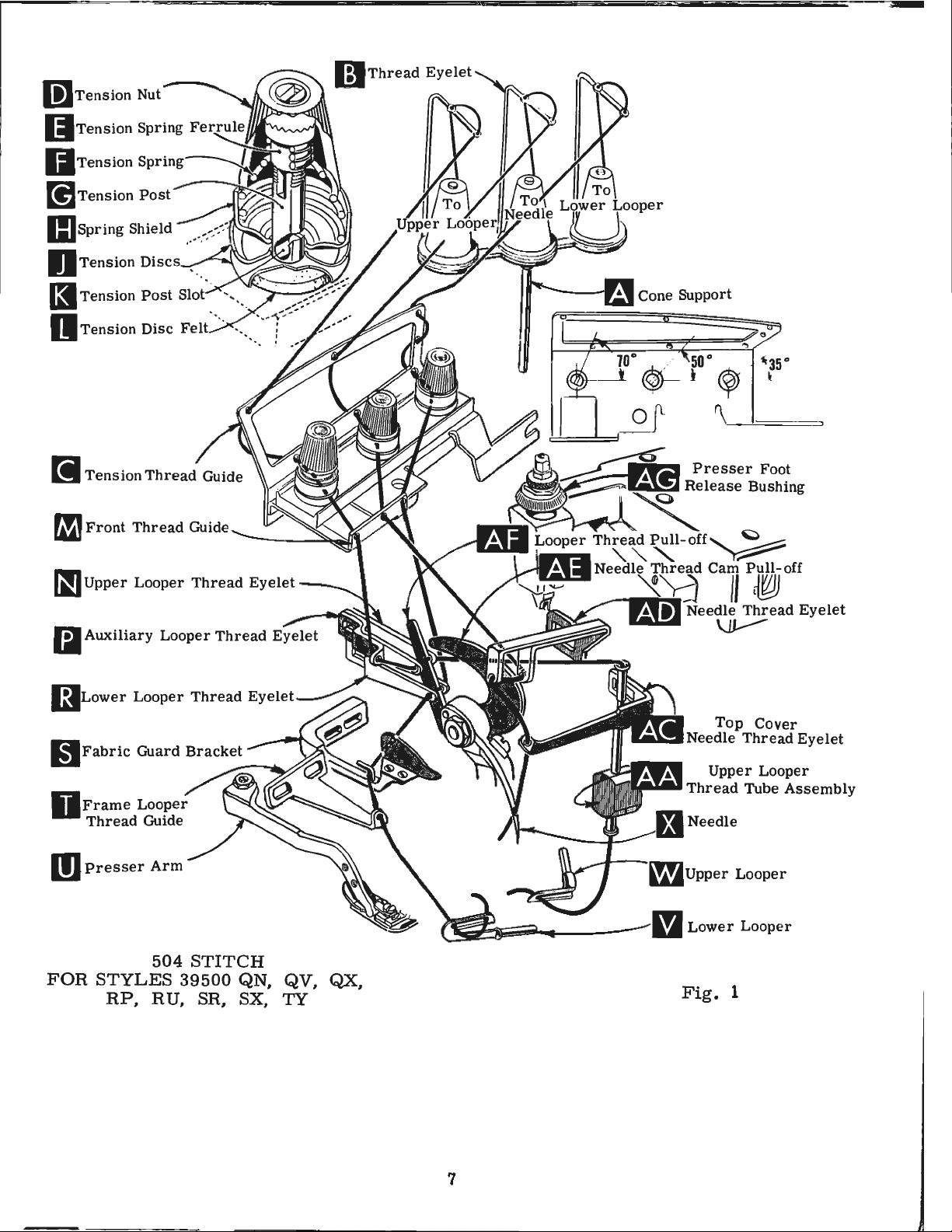
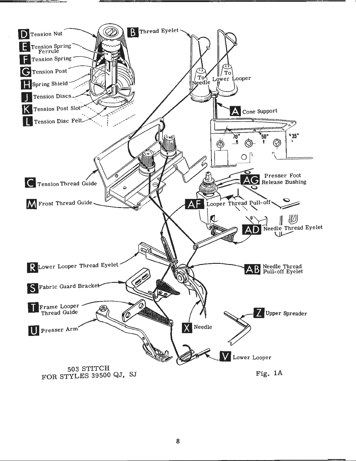
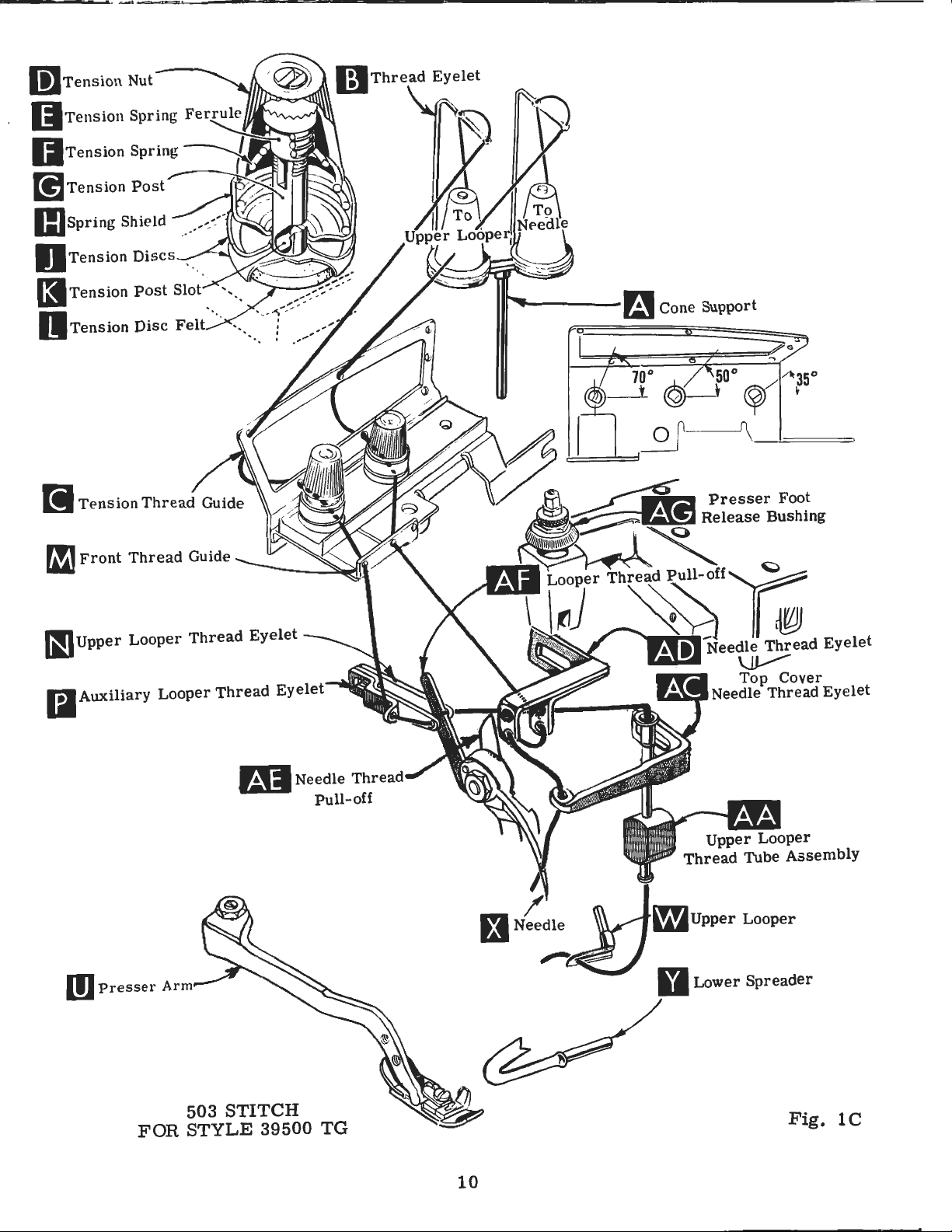
THREADING
Only
1 B
and 1 C).
It
quence
needle
quence
first.
direction
by
position.
tension
(M.
eyelet
of
frame
lower
left
hand.
upper
Before
turning
Be
TO
Double
Fig.
looper
to
parts
Parts
will
simplify
of
threading
second
whenusing
looper
beginning
until
presser
sure
discs
THREAD
(R.
looper
looper
right.
end
1.
lA
Fig.
thread
Left
hreads,
(J)
thread
involved
when
the
needle
and
THE
of
thread
or
1,
pull-off
(V)
is
eye
are
placed
the
threading
the
using
504
second,
to
(X)
foot
as
in
diagonal
LOWER
lB).
lA
or
guide
all
of
in
threading
lower
the
or
and
thread,
is
release
they
and
Then
lB)
(AF).
(T).
the
way
lower
in
their
of
looper
503
stitch
505
stitch
the
swing
at
high
bushing
come
slots
LOOPER
lead
lead
from
it
thread
right
Lead
Turn
to
looper
are
shown
relative
these
needle
from
through
handwheel
the
machines
or
upper
(Fig.
(Fig. 1 and
cloth
position,
(AG)
the
(K)
in
(FOR
through
to
thread
left.
can
be
positions
third.
plate
tension
tension
ALL
the
left.
behind
then
threaded
in
threading
looper
lA
and
lB)
open,
release
and
STYLES
right
both
NOTE:
in
operating
thread
to
follow
first
lC).
is
turn
swing
thread
posts
eyelet
eyes
fabric
easily
diagrams
for
clarity.
the
(as
The
tothread
handwheel
pressure
presser
guide
(G).
EXCEPT
of
Thread
guard
direction
through
if
recommended
applicable)
recommended
the
on
arm
(C).
39500
of
front
lower
tweezers
looper
must
(S)
both
(Fig.
lower
in
operating
presser
(U)
are
between
thread
pass
and
until
eyes
are .in
1.
lA,
se-
and
the
se-
looper
foot
out
of
TG)
guide
thread
in
front
through
heel
of
from
left
TO
Thread
lB
or
Lead
through
must
thread
through
then
insert
CAUTION!
passing
Turn
highest
Fig.
lA
to
front.
hole
the
in
front.
THREAD
lC).
thread
both
pass
in
tube
thread
from
TO
handwheel
position.
or
lB).
Now
needle
UPPER
upper
Then
assembly
thread
turn
through
eyes
front
tube
Be
tube
THREAD
Insert
then
lead
thread
looper
handwheel
auxiliary
of
upper
of
looper
(AA).
assembly
through
sure
assembly
THE
in
operating
thread
lead
the
needle
pull-off
LOOPER
thread
looper
looper
thread
lead
(AA).
upper
upper
to
upper
NEEDLE
through
thread
thread
eyelet
(FOR
through
until
thread
pull
thread
Pull
looper
looper
looper
(FOR
direction
through
under
(AB)
ALL
left
point
thread
eyelet
-off
under
thread
eye
thread
the
eye
STYLES
eyelet
of
upper
eyelet
(AF).
neck
from
is
eye.
STYLES
until
middle
of
needle
the
neck
from
of
(N)
from
After
of
out
bottom
front
under
39500
needle
eyelet
of
right
EXCEPT
front
looper
(P)
from
left
top
to
back.
lower
(X.
of
thread
top
cover
to
left.
thread
(W)
back
to
pulling
cover
of
tube;
looper
QJ,
QL
Fig.
front
eyelet
casting
Thread
39500
guide
is
all
right.
up
casting
push
and
lA
or
thread
(AD)
QJ,
( M,
the
to
front,
Note:
upper
tube
thread
SJ)
lB)
from
and
needle
SJ)
Fig.
way
thread
looper
and
down.
is
guide
through
left.
then
down
when
at
its
(M.
back
from
1,
11
Page 12

TO
THREAD
THE
NEEDLE
(FOR
ALL
STYLES
EXCEPT
39500
QJ,
QL
and
SJ)
Turn
highest
Fig. 1 or
thread
cover
tension
to
eyelet
needle
The
secure
Fig.
handwheel
position.
1 C,
then
(AD),
thread
amount
nuts
(D,
proper
2
Insert
insert
of
tension
Fig.
stitch
in
operating
thread
needle
under
eyelet
1,
lA,
formation.
should
decrease
nut
screw
pressure,
adjusting
(A).
ing
to
justing
through
thread
neck
1 / 16
of
(AC).
THREAD
on
the
lB
Sufficient
be
(A,
has
With
nut
( C)
inch
screw
FEED
direction
the
from
top
cover
Thread
needle
or
lC).
PRESSER
presser
maintained.
amount
Fig.
2)
and
a
right
loosening
screw
presser
so
(B)
that
(.
79
(B).
ECCENTRICS
until
middle
right
casting;
needle
TENSION
and
Tension
of
foot
its
to
Set
from
looper
foot
Should
pressure
turn
hand
decreases
has
been
resting
under
1. 59
cap
needle
eyelet
to
left,
then
the
threads
on
threads
FOOT
pressure
it
adjusting
thread,
properly
on
surface
mm)
(D)
against
(X,
Fig. 1 or
of
front
through
down
front.
is
should
PRESSURE
to
be
necessary
on
presser
screw
so
tightening
pressure.
throat
is
from
the
locking
lC)
thread
both
eyes
through
regulated
feed
foot,
set,
plate,
approximately
top
hole
by
be
only
work
to
increase
loosen
(B).
When
tighten
position
surface
nut
is
at
its
guide
of
uniformly
Adjusting
increases
pressure
(C).
(M,
needle
in
top
knurled
enough
lock
lock
nut
lock-
1/32
of
ad-
or
Feed
approximately
eccentric
mately
specified,
exploded
The
-5. -6,
-28,
Additional
39540 B with a minor
stitches
Before
cloth
lower
NOTE:
chines
eccentrics
is
the
views
following
-7,
-30,
desired.
plate,
knife
Adjusting
covered
5
stitches
No.
39540
number
machine
in
catalog
-8, -9,
-32,
eccentrics
-34, -36,
Example:
ASSEMBLING
assembling
fabric
holder
assembly;
instructions
in
this
of
Style
stitch
guard,
SETTING
used
in
Style
per
inch.
B-5.
stitches
number
-10, -11, -12,
may
number
catalog,
39500
for
-40.
be
"39540
and
chip
then
Minor
obtainable
QJ
eccentrics
feed
Only
ordered
suffixed
AND
adjusting
guard,
follow
will
unless
THE
39500
It
B-5".
NEEDLE
QJ
will
be
numbers
when
will
be
furnished
eccentrics
-13, -14,
one
eccentric
separately.
to
ADJUSTING
sewing
upper
this
pertain
otherwise
machines
noted
using
shipped
indicate
knife
suggested
to
that
of
the
on
are
-15,
is
SEWING
parts,
assembly
all styles
specified.
have
been
the
part
that
with
available
-16, -18,
To
symbol
eccentric.
above
other
supplied
order
approxima
PARTS
remove
sequence.
of
part
Styles
under
-20.
with
an
and
ma
-
selected
number
indicate
Unless
eccentric.
of
machines.
No.
-22, -24,
each
eccentric,
ely
the
to
produce
of
the
approxi-
otherwise
Refer
39540
number
B-4,
machine.
use
feed
to
-26,
No.
of
With
should
high
position,
above
1/2
inch(12.
throat
center
throat
in
ne
plate
70
mm)
plate
the
edle
(Fi
(A, Fig. 3) assembl
front
for
point
g.
3)
Styl
end
of needle
should
for
Styl
es 39500
be set
es
QN
ed
in
slot.
33/64 inch
39500
and
12
QJ,
SR;
position, needle
When needle
(13.
QL,
and
10
RP a
nd
15/ 32 in
is
at
mm)
SJ ;
ch
Fig. 3
Page 13

(11.
91
height
clamp
remove
On
if
needle
looper
thread
off
screw,
ing
arm.
At
lower
39500
lower
1/8
looper
inch
using
39500
lower
and
looper
lower
needle,
spreader
mm)
above
screw
throat
all
thread
thread
pull
be
this
looper
TG
insert
(3.17
looper
QJ,
spreader
using
deflecting
for
the
(C).
plate.
Styles
pull-off
-off
back.
sure
point
(A,
at
left
mm)
QL,
point
looper
Styles
39500
throat
After
except
cam
pull
(B),
When
to
take
on
all
Styles
Fig.
lower
end
from
gauge
QN, QV,
for
Styles
point
gauge
needle.
SETTING
QV,
plate,
needle
39500
-off
(A,
separate
retightening
upend
except
5)
into
spreader
of
its
stroke,
center
No.
21225-1/8
RP,
39500
for
Style
No.
Tighten
THE
QX,
RU,
move
QJ,
has
needle
been
QL,
Fig.
by
movinglooper
play
inneedle
39500
bar
(B).
into
bar
set
of
needle
RU,
SJ
QX,
39500
21225-3/32.
nut
NEEDLE
SX,
TG
driving
properly
SJ
and
4)
overlaps
looper
TG,
insert
On
(B).
looper
(Fig.
for
Styles
and
SR.
SX
and
TG
(C).
(Continued)
and
TY.
arm
set,
TG,
pull
-
driv-
Style
With
point
5).,
Set
TY;
3/32
Do
inch
not
To
(2.
have
align
(B,
Fig.
tighten
38
mm)
lower
needle
3)
clamp
Fig.
from
looper
or
by
loosening
screw
4
center
or
set
lower
the
and
of
Now
to
the
7)
until
•
002-.
SETTING
Now
to
the
7 A)
until
surface
Fig.
SETTING
finish
right,
the
needle
004
inch(.
THE
lower
its
5
THE
point
springs
051-.102
LOWER
complete
right,
the
its
point
needle
another . 002-.
looper
the
should
springs
LOWER
should
forward
mm).
SPREADER
spreader
004
inch(.
Now
Set
possible,
looper
deflect
mm).
Make
needle
LOOPER
adjustment.
be
set
into
from
adjustment.
be
set
into
forward
051-.102
assemble
SETTING
rear
without interfering
or
lower
needle
Screw
sure
there
guard
(ALL
As
lower
the
needle
rear
guard
(STYLE
As
the
needle
from
mm).
THE
needle
spreader,
forward.
(B)
is
is
and
lower
STYLES
looper
scarf
surface
39500
spreader
scarf
rear
the
main
REAR
guard
used
no
interference
looper
EXCEPT
TG
ONLY)
(A,
needle
feed
NEEDLE
(A,
but
002-.
to
set
moves
(A,
Fig.
another
moves
Fig.
guard
dog.
Fig.
with eith
still
004
inch(.
rear
or
spreader.
39500
GUARD
6)
as
er
in
position
051-.102
needle
between
TG)
high
lower
guard.
rear
as
to
Assemble
springing
as
possible
and
set
between
SETTING
needle
to
front
needle
needle
front
needle
THE
off
guards
FRONT
needle
back
guard,
without
guard.
and
guard
touching.
After
feed
dog.
NEEDLE
(C,
Fig.
set
front
Screw
this
setting
GUARD
6).
When
needle
(D)
is
make
guard
used
13
spread
as
to adjust
sure
er
close
ther
is
e is
Fi
g. 6
no
interference
Page 14

SETTING
THE
UPPER
LOOPER
(ALL
STYLES
EXCEPT
39500
QJ,
SJ)
Insert
its
holder
Fig.
of
looper
of
upper
set
upper
lower
looper
clearance
upper
and
7
and
looper
looper
(Fig.
looper
permits
the
casting.
shaft
point
eye
9).
(A,
it
to
upper
in
holder
the
looper
place.
in
shank
holder
SX
and
39500
RP
When
upper
shank
(Fig.
SR
be
and
set
looper
about
8).
to
slightly
Styles,
By
and
by
turning
to
cross
with . 002
Fig.
be
pushed
holder
Screw
the
extends
(Fig.
TY;
and
the
vertical
On
TG
the
position
back
there
adjusting
lower
to . 004
8)
in
its
holder.
in
or
out
into
upper
(C,
Fig.
shaft.
8),
1/32
1/16
for
Locate
Styles
to
1/16
to
TG.
upper
holder
Styles
upper
of
vertical.
the
looper
should
on
Styles
39500
looper
upper
is a clearance
looper
the
looper
around
looper
inch
(.
051
or
8)
on
upper
3/32
39500
inch
is
be
QL,
holder
looper
Be
sure,
between
holder
to
the
to • 102
Screw
turned
looper
clamp
looper
inch
(.
at
set
39500
RP,
in
its
left
(B)
around
shaft,
(1.
QL,
79
to
the
right
to
QN,
RU,
should
shank
on
all
heel
or
out
shank,
of
the
mm)
holds
if
holds
in
its
59
to
2.
QN,
QV,
1.
59
end
position
QV,
upper
its
it
the
38
mm)
QX,
shank.
is
not
upper
holder
mm)
QX,
for
of
its
upper
SX
looper
Insert
already
loop
so
beyond
RU,
Styles
stroke,
looper
and
in
er
that
SR,
TY
As
heel
head
of
with
Next,
travel;
needle
looper
39500
as
follows:
centers
(Fig.
the
bottom
the
the
check
and
holder
QL
Fig.
on
12).
upper
upper
1/32
turn
looper
looper
to
1/16
handwheel
dimensions
throat
and
(A,
RP.
plate
Fig.
8
As the
the needle,
For
Styles
of
the
needle
moves
should
inch(.
of
(Fig.
10).
NOTE:
the
other
example,
ion
is
holder
left
end
dimension
looper
looper
made
looper
tain
the
When
for
Styles
SR,
SX
upper
looper
the
39500
eye
toward
pass
79
to
until
looper
upper
10).
If
Figure
For
Styles
1/2
increased
the
behind
1.
59
is
looper
resetting
10
represents
the
dimensional
refer
inch
by
counterclockwise,
of
machine;
is
increased
holder
to
the
shaft. After
it
may
be
necessary
around its
condition
the
39500
and
TY
shank
shown
correct
QL,
it
can
is moving
eyes
of
RU
and
should
the
TG
be
upper
about
top
of
its
the
lower
mm)
at
the
point
is
clearance.
left
with
necessary,
the
settings
to
Fig.
(12.
70
mm)
turning
upper
looking
5 / 3 2
by
left,
these
inch ( 3.
pulling
out
changes
to
turn
slightly
in
(Fig.
setting
is
QN, QV,
be
checked
to the right and
looper
when
the
level
looper
with
stroke,
the
looper
end
of
its
respect
dimensional
do
to
it
bymoving
setting
of
11.
For
dimens-
looper
from
9 7
mm)
upper
of
upper
are
upper
to
main-
9).
obtained
QX,
RP,
quickly
the
upper
and needle should
eye
centers
the
top
surface
Fig.
7A
theupper
for
Styles
Fig.
loop
9
er
align exactly
on
the
needle,
of
the
looper.
eye
14
Page 15

SETTING
THE
UPPER
LOOPER
{ALL
STYLES
EXCEPT
39500
QJ,
SJ)
{Cont.)
Check
downstroke.
slightly
of
machine.
Machine
39500
39500
and
Styles
QL,
QN,
3 9 500 QV,
39500
39500
39500
RU
SR
TG
setting
If
needle rubs
rotate
Reset
RP
TY
QX,
SX
to
avoid
interference
the
looper a short
to
maintain
dimensions
Looper
Needle
5/32
9/64
9/64
5/32
9/64
5/32
back
distance
Point
Center
inch
inch
inch
inch
inch
inch
of
Fig.
(3.
(3.
(3.
(3.
(3.
(3.
between
upper
upper
looper,
counterclockwise,
of
Figs.
10
to
Left
Of
line
97
mm)
57
mm)
57
mm)
97
mm)
57
mm)
97
mm)
9,
looper
pull
10,
and
looper
looking
11,
12.
Looper
Throat
1/2
1/2
1 5 / 3 2
29/64
31/64
15/32
needle
out
inch
inch
inch
inch
inch
inch
of
from
Point
Plate
(12.
(12.
(11.
(11.
(12.
(11.
on
needle
its
hold
left end
Above
70
mm)
70
mm)
91
51
30
91
er
mm)
mm)
mm)
mm)
to
left,
behind
(.
051
looper
Fig.
the
the
12
Vee
eye
to . 102
(Fig.
of
mm)
9A).
notch
the
lower
clearance
SETTING
Insert
(B)
holds
pushed
holder
{C,
shaft,
in
into
Fig.
and
Preliminary
of
its
stroke,
er
shank
Top
end
of
extend
1.
59
er
of
mm)
(Fig.
As
the
1/32
8A).
spreader
spreader
looper,
between
THE
upper
upper
or
out
spreader
8A)
allows
Setting:
spreader
about
spreader
to
above
with.
Fig.
UPPER
11
SPREADER
spreader
spreader
or
turned
shaft,
on
clamp
collar
holder
When
holder
vertical
(Fig.
shank
1/16
the
moves
should
inch
spreader
002
to . 004
from rig
pass
spreader and
(A,
in
its
around
if
to
be
upper
should
(.
79
hold-
lower
Fig.
holder,
it
is
not
holds
rotated
spreader
should
8A).
to
ht
just
inch
(STYLES
8A)
in
and
its
shank.
already
spreader
or
be
set
39500
its
holder.
permits
Insert
in
place.
holder
adjusted
is
at
the
to
position
QJ
and
Screw
it
to
spreader
Screw
in
laterally.
right
spread-
SJ)
be
the
end
left
Turn
end
of
the
handwheel
its
travel.
At
until
this
upper
position,
spreader
the
is
lower
at
point
15
the
Fig.
8A
Page 16

SETTING
of
the
line
of
THE
spreader
the
needle
UPPER
should
and
SPREADER
extend
should
plate
ing
about
be
the
31 /
64
(Fig.
spreader
(STYLES
5/32
inch
l0A).
inch
(12.
If
holder
39500
(3.
97
30
mm)
resetting
(A,
QJ
mm)
is
Fig.
and
SJ)
to
the
above
necessary,
10A).
(Cont.)
left
the
top
of
do
of
the
the
it
center-
throat
by
mov-
feed
bar.
The
appear
justing
of
travel,
3/64
inch
39500
throat
of
throat
SR
and
be
set
Fig.
feed
above
pin
(1.
TY
which
plate.
plate,
SX.
to
the
in
the
19
On
same
9A
dogs
the
place.
top
mm)
should
Now
for
Style
should
throat
With
of
the
above
set
Styles
39
height
needle.
out
ward
opposite
spreader
feed
spect
pin
be
plate.
the
teeth
the
rise
the
chaining
39500
500
QV,
as
the
Now
of
its
a
check
If
needle
holder
short
movement,
and
Assemble
dog
(B).
to
the
(C).
set
This
level
Screw
feed
throat
on
dogs
the
plate,
depth
feed
the
dog
QJ,
QL,
chaining
main
distance.
needle.
SETTING
chaining
Main
throat
pin
at
(D)
locks
at
main
of a full
teeth
QN,
feed
dog
setting
rubs
the
slightly
will
Reset
feed
plate
raises
the
time
feed
their
feed
on
all
tooth
flush
QX,
feed
dog
teeth.
between
back
and
These
reduce
THE
feed
dog
by
rotating
or
teeth
tilting
highest
dog
should
Styles,
above
with
RP,
teeth
of
rotate
to
lower
FEED
dog
should
lowers
first
point
except
the
RU,
should
upper
spreader,
spreader
same
the
adjustments,
clearance
looper
DOGS
(A,
Fig.
be
levelled
feed
the
ad-
be
the
top
SJ,
spreader
pull
holder
(Fig.
13)
tilting
back
Fig.
spreader
for-
between
9A).
to
main
with
adjusting
end
of
l0A
and
in
re-
the
NOTE:
C
screw
be
locked
Styles
(B)
also
with
39500
serves
nut
(C)
TG
Fig.
as
even
or
TY
DO
SETTING
13
latch
pin
when
scr
NOT
THE
for
ew
have a chaining
LOWER
KNIFE
assembly.
14)
flush
Adjustments
gonal
lower
pressed
no
ary
i n
screw
against
the
is
cloth
not tig
plate
htened
feed
Replace
dog.
lower
Lower
should
with
be
set
throat
are
head
knife.
screw
Lower
against
lateral
when
Lower
any
adjustment
width
knife
position
(B)
and
support
latch spring,
agai
nst
lower
knife
with
plate
made
knife
upper
of
trim
may
locking
bracket.
it
should
knife
knife
(A,
cutting
surface.
with
which
is
knife,
is
necess-
is
changed.
be
secured
by
tightening
nut
Because
holder.
holder
Fig.
edge
hexa-
holds
spring
so
(C)
always
16
Page 17

SETTING
THE
UPPER
KNIFE
Replace
setting
At
than
should
the
nut
bottom
1/64
be
After
trim,
screw
holding
when
upper
Length
Note
that
machine
ploded
views
machines.
In
assembling
sure
of
side,
on
key.
the
feed
so
the
feed
Assemble
upper
(E)
to
of
inch
set
down
upper
(H)
block
(J)
knife
SETTING
of
stitch
the
part
Style
39500
in
hub
and
eccentric
the
undercut
eccentric.
knife
hold
its
stroke,
(.
40
mm)
against
knife
should
in
place.
is
replaced.
is
number
QJ
catalog
the
oil
groove
spacer
washer
assembly.
clamp
(F)
front
below
the
has
been
be
tightened
This
THE
STITCH
determined
of
the
is
No.
for
eccentric
feed
eccentric
is
(B)
should
on
the
spacer
Be
careful
(D)
and
in
its
cutting
cutting
upper
set
will
LENGTH
by
feed
39540
to
the
not
tighten
Clamp
most
edge
knife
for
proper
to
lock
simplify
feed
eccentric
eccentric
B-5.
on
(A,
left.
also
will
be
to
damage
nut
upper
clockwise
edge
of
of
and
upper
Refer
other
Fig.
Beveled
be
to
over
(C)
securely.
knife
upper
lower
slightly
width
knife
resetting
used.
used
to
on
ex-
Styles
15),
be
edge
the
left
the
hub
shaft
or
(D,
position
knife
knife.
back
of
of
Fig.
14)
against
should
The
extend
chain
from the
in
position,
upper
not
guard
cutting
knife.
less
(G)
edge.
To
(D)
and
operating
eccentric
and
withdraw
slightly
foot
can
change
feed
direction
extractor
during
Fig.
be
raised
feed
eccentrics,
eccentric
until
(E),
eccentric.
extraction.
15
no high
spacer
key
supplied
It
may
needle
position
(front
of
needle
edge
that
plate.
throat
(H,
(B,
lifter
tighten
(B)
bind
ed.
er
than
remove
(B).
Turn
slot
in
with
be
necessary
Assemble
in
high
and
and
back)
hole
of
needle
the
bottom
If
necessary,
plate
Fig.
Fig.
16).
16)
lever
collar
The
foot
secure
and
rise
Adjust
upper
nut
(C),
handwheel
eccentric
machine,
SETTING
the
position,
set
the
and
in
presser
hole
of
slots
To
move
and
clamp
shaft
to
screws
lifter
the
shaft.
when pres
lift
er
lever stop
looper
washer
is
reach
to
presser
presser
flat
in
throat
the
presser
presser
by
shifting
the
and
lever
Be
ser
or spread
toward
move
THE
swing
on
foot
the
screw
left
clamp
arm
sure
foot
in
the
behind
handwheel
PRESSER
foot
to
presser
foot
throat
must
plate.
foot
foot
can
the
foot
shaft,
(G)
and
or
right
screw.
(A,
Fig.
the
presser
r e
lease
screw
er
will
front.
eccentric
FOOT
presser
to
align
plate.
be
aligned
It
is
be
flat
be
lifter
loosen
then
as
16)
bushing is
(C)
permit;
Fig.
Using
back
arm
into
needle
The
also
on
realigned
lever
collar
shift
required.
and
arm
so
that
14
hooked
as
shown
and
forth
arm.
With
sewing
holes
front
with
edge
front
important
the
throat
with
shaft
screws
the
the
collar
does
unlock-
presser
then
lock
foot
Re-
not
17
Page 18

the
nut
inch
lifter
rise.
screw
the
chip
To
assemble
upper
tion.
SETTING
(D).
(1.
59
lever
This
(E)
and
guard,
knife
THE
(
Continued)
There
to
before
3.
should
17
the
adjustment
locked
fabric
chip
guard,
assembly
PRESSER
mm)
presser
should
with
guard
reaches
be
free
nut
turn
FOOT
from
motion
foot
be
(F).
Re-assemble
and
cloth
handwheel
its
highest
1/16
begins
made
to
of
foot
with
plate.
until
posi
1/8
to
-
CLOTH
PLATE
CAUTION:
loosen
plate
the
with
assembled.
In
assembly,
stud
are
tightened
turn
in
cloth
machine
towards
ly
which
that
ed
according
only
Be
with
the
collapses
sure
threaded
according
Fig.
REMOVAL
When
cloth
the
plate
cloth
plate.
the
rear.
the
cloth
machine
to
according
to
Fig.
16
removing
stud
plate
the
cloth
to
the
The
cloth
flat
and
Stud
locking
the
body
plate
will
Styles
threading
to
threading
lB
and
AND
the
locking
stud
(C)
plate
point
plate
"V"
slot
screw
of
turn
STARTING
39500
diagram
machine
ASSEMBLY
cloth
screw
and
cloth
screw
of
removing
is
then
of
the
(B)
the
stud
when
QN, QV,
Fig.
diagram
Style
plate
(B)
and
plate
and
the
all
assembled
cloth
is
tightened
to
the
opening
TO
OPERATE
QX,
1.
Fig.
39500
(A,
Fig.
lift
up
screw
\
cloth
play
plate
and
stud
secure-
screw
or
closing.
RP.
RU,
Machine
lA.
Thread
TG
according
cloth
plate
to
(D)
Styles
17)
(D).
yet
the
(C)
so
SR, SX
machine
39500
to
and
Fig.
Fig.
TY
are
QJ
Style
lC.
17
thread-
and
39500
SJ
are
QL
With
or
thread
in
the
presser
Swing
While
needle
be
just
if
excessive
tion
needle
contacts
It
ator)
thread
middle
foot
presser
thread
tight
needle
is
desirable
to
delay
eyelet
of
in
foot
sewing
is
enough
thread
thread
slightly,
tensions
(R,
Fig.
their
place,
into
NEEDLE
on
material,
drawn
to
is
eyelet
thread.
to
adjust
light,
lA)
front
to
make
position,
on
needle
feed
pulled
(AD,
the
set
and
thread
to
back
sure
insert
THREAD
check
down
chain
on
the
off
up
Fig.
the
needle
tightening
looper
eyelet
locations.
chain
material
CONTROL
needle
stroke.
stitch
stroke.
1)
so
that
thread
of
the
18
thread
forms
thread
At
tongue.
With
needle
eyelet
needle
eyelets
(N,
Operate
and
and
(504
top
Stitch
needle
thread.
(N
and
Fig.
lC)
about
machine
moves
sew
off
slowly.
STITCH)
control
of
thread
well
as
follows:
needle
tends
at
bottom
stroke,
to
cam
-forward ( toward
R,
Fig. 1 and
horizontal
slowly,
the
tongue
thread
pull
down
of
stroke,
pull-off
without
freely.
Usually
should
slightly
posi-
(AE)
the
oper-
lB)
and
all
just
Page 19

NEEDLE
THREAD
CONTROL
(Styles
39500
QJ,
SJ,
TG
- 503
STITCH)
While
of
needle
increase
and
1 C)
While
of
needle
To
1 B)
farther
With
back
its
mm)
far
most
distance
should
looper
While
portion
looper
the
tension
eyelet
sewing
thread
thread
farther
NEEDLE
sewing
thread
increase
material
enough
rearward
be
set
(V)
heel
sewing
of
lower
thread
while
(R)
down,
to
the
behind
with
comes
on
material,
required
drawn
to
the
THREAD
on
material,
required
thread
rear.
LOWER
under
so
thread
position.
needle
its
eyelet
eyelet
on
looper
off
lower
keeping
for
on
downstroke,
rear.
for
drawn
LOOPER
presser
is a little
Looper
thread
approximately
at
the
time
material,
thread
upper
looper
the
same
check
the
stitch
CONTROL
check
the
stitch
on
downstroke,
THREAD
foot,
slack
thread
cam
lower
check
should
looper.
thread
is
amount
needle
should
position
(Style
needle
should
CONTROL
set
when
pull-off
pull-off
1/8
looper
drawing
be
drawn
To
increase
on
upper
of
thread
be
needle
39500
thread
be
position
lower
looper
(AE).
inch
is
off
pull
-off
control
drawn
QL -505
control
drawn
needle
(504
looper
thread
(AF)
Frame
(3.
17
at
extreme
of
looper
through
amount
looper,
action.
on
thread
on
needle
thread
STITCH)
thread
is
set
mm)
the
of
move
as
follows:
needle
eyelet
STITCH)
as
follows:
eyelet
pull-off
about
looper
to
left
thread
tension
thread
lower
About
downstroke.
(AD,
About
downstroke.
eyelet
(AD,
(R,
1/32
thread
the
end
(AF)
right
as
inch(.
guide
of
its
follows:
reaches
of
before
drawn
looper
75%
To
Fig.
lA
60%
Fig.
Fig.
1)
79
(T)
lower
travel.
A
lower
through
thread
With
back
and
treme
Frame
inch
(3.
extreme
Set
forward
Frame
inch
(3.
at
the left
Before
three
will
tensions
not
material
down
left
position.
looper
17
mm)
left
lower
in
its
looper
17
mm)
end
proceeding
markedly
LOWER
under
far
enough
Lower
thread
to
the
end
of
its
LOWER
looper
slot.
thread
to
the
of
its
stroke.
UPPER
to
give a normal
affect
LOOPER
presser
so
looper
guide
right
of
travel.
LOOPER
thread
guide
right
LOOPER
to
adjust
the
purl.
thread
heel
eyelet
(T)
of
lower
appearing
THREAD
foot,
is a little
thread
(T)
should
eyelet
THREAD
(R,
should
looper
THREAD
upper
looper
CONTROL
set
lower
eyelet
be
set
of
looper
CONTROL
Fig.
be
1 B)
set
(V)
CONTROL
thread
stitch.
looper
slack
(R)
with
(V)
about
with
heel
Moderate
(503
thread
when
should
its
at
the
(505
horizontal
its
eyelet,
(504
eyelet
STITCH)
eyelet
spreader
be
about
eyelet
approximately
time
STITCH)
eyelet
approximately
when
STITCH)
(N,
Fig.
change
(R,
reaches
horizontal.
lower
and
lower
1)
in
these
Fig.
its
looper
all
the
looper
balance
tensions
lA)
ex-
1/8
is
way
1/8
all
at
is
,
During
draw
is
upper
drawn,
pull-off
ne
looper
upper
reaches
edle downstroke,
thread
looper
its
most
through
thread
rearward
forward
the
will
have
position.
stroke
tension.
almost
of
When
all
looper
normal
slack
19
thread
amount
taken
pull-off
of
up
as
(AF)
looper
looper
will
thread
thread
1
Page 20

UPPER
LOOPER
THREAD
CONTROL
(503
STITCH -Style
39500
TG)
With
back
its
extreme
to
rest
thread
Fig.
to
have
If
all
end
that
to
form
edge.
upper
material
and
down
With
To
it
Position
material
on
top
is a little
move
1)
should
slightly
it
becomes
play
is
higher
near
looper
under
far
enough
left
position.
UPPER
under
of
lower
slack
the
purl
be
raised
more
necessary
in
needle
over
top
edge.
POSITIONING
of
lower
thread
tensions.
presser
so
thread
Looper
LOOPER
presser
looper
when
POSITIONING
more
keeping
pull-off
drive
throat
If
upper
looper
thread
upper
under
on
to
move
shaft
plate
looper
THE
thread
THREAD
upper
foot,
is a little
thread
foot,
eyelet
looper
THE
the
the
same
looper
before
than
recommended
is
SQUARE
at
set
upper
slack
eyelet
set
reaches
PURL ( 504
edge,
thread
tightening.
too
the
(N)
CONTROL
upper
(R),
and
both
amount
than
thread
low,
EDGE
edge
looper
should
looper
back
the
STITCH)
looper
of
on
pull-off
the
(505
is
located
thread
when
(505
thread
far
left
thread
pull-off.
lower
If
upper
in
Fig.
purl
STITCH)
eyelet
lower
be
about
STITCH)
eyelet
enough
end
of
its
Usually
thread.
(AF),
will
by
be
looper
10,
form
balancing
(N,
spreader
horizontal.
(N,
so
upper
stroke.
eyelets
sure
is
the
purl
nearer
Fig.
reaches
Fig.
looper
(N
and
it
is
better
to
take
located
will
bottom
needle
lC)
lB)
R,
up
so
tend
and
To
increase
The
being
ble
should
purl
UNION
poration,
to
Maximum
parts
is
a
driver,
of
sewn.
without
be
is
pulled
Success
SPECIAL
the
most
Genuine
are
your
Torque
distance
torque
reduce
lower
needle
In
general,
causing
increased
too
in
its
subsidiaries
approved
efficiency
needles
stamped
guarantee
(measured
by a lever
etc.
Many
will
tighten
amount
looper
thread
needle
far
USE
the
operation
Needles
with
of
of
these
of
lower
thread
tension
lower
thread
as
long
over
scientific
and
are
the
(in
the
the
GENUINE
and
and
durability
packaged
the
Union
highest
in
inch-pounds)
inches
devices
part
looper
tension.
THREAD
required
looper
to
as
the
top.
NEEDLES
of
these
Repair
authorized
principles,
are
with
Special
quality
TORQUE
or
feet).
are
to
the
thread
is a function
thread
be
pulled
elasticity
machines
Parts
assured.
labels
in
REQUIREMENTS
is a rotating
available,
correct
in
the
TENSIONS
tension
down.
of
the
AND
as
distributors.
trademark,
materials
This
REPAIR
can
furnished
and
are
marked~
is
accomplished
which
amount
stitch,
of
should
Upper
chain
be
made
U S
and
force
when
and
or
close
needle
PARTS
secured
by
They
Emblem.
workmanship.
(inpounds)
no
thread
be
set
looper
increases,
the
Union
are
designed
with
by a wrench,
set
at
tighter.
the
edge
and
as
high
as
thread
or
only
utmost
@ .
the
with genuine
Special
according
precision.
Genuine
Each
trademark
applied
proper amount
more,
material
possi-
tension
until
the
Cor-
repair
through
screw
All
unless
by
hand
straps
otherwise
as
The
screws
and
tightly
eccentrics
noted.
as
possible,
requiring
All
a
should
other
unless
specific
be
tightened
nuts,
otherwise
torque,
20
bolts,
will
to
19-21
screws,
noted.
be
indicat
inch-pounds
etc.,
ed
s
on
hould
the
(22-24
be ~ig
pictu
cm/kg)
htened
re pla
tes.
Page 21

TO
REMOVE
Fig.
18
CRANKSHAFT
Crankshaft
1.
Drain
of
2.
Remove
3.
Remove
eccentric
4.
Remove
Remove
5.
will
6.
Remove
through
can
oil
base.
top
feed
key
be
re-assembled
screw
bottom
be
withdrawn
by
removing plug
and
bottom
eccentric
extractor,
(D).
three
counterweights (E).
(F)
of
bed
nut
slip
in
which
castin
easier
screw
covers
(A,
off
the
holds crankshaft split bea
if
of
Fig.
the
eccentric
proper
g.
these
located
machin
18)
and
Identify
place
steps
on
e.
washer
s
(C).
s .
are
back
these
21
followed:
of
machine
(B),
and,
counterweights s o that they
rin
g. T
near
with
his scr e w i s
bottom
the
aid
rea
edge
of
ched
the
Page 22

7.
Remove
crankshaft
When
caps
original
are
the
should
the
should
same
were
8.
Loosen
which
ing
nut
driving
upper
bearing
same
caps
at
re-assembling
make
stamped
caps
bearings.
arm
is
sure
position.
and
be
on
be
reassembled
holes
removed.
clamp
holds
(B).
through
arm
knife
cap
precautions
TO
of
points
they
on
both
both
the
Also.
from
nut
upper
Access
top
to
the
driving
(E).
This
REMOVE
bearings
G.
are
Trade
halves
trade
same
which
(A.
Fig.
knife
to
cover.
left
lever
is
when
CRANKSHAFT
on
Hand
bearing
in
side
screws
re-assembling
J.
their
marks
of
marks
of
in
the
they
19)
driv-
clamp
Draw
until
(C)
at
bearing
and
connecting
point
cap
(Continued)
rod
(K,
Fig.
as
described
(D)
Fig.
drop.
18)
19
allowing
on
crankshaft.
in 7 above.
removal
Observe
of
9.
10.
11.
12.
13.
14.
15.
16.
Remove
screw
Loosen
Remove
Loosen
Remove
collars
Crankshaft
If
arbor
against
Carefully
assembly
various
helpful.
is
two
two
(V)
necessary
press.
ground
parts
screw
reached
screws
screw
screws
three
and
may
to
In
observing
of
crankshaft.
and
(L.
Fig.
through
(M)
(N);
take
(R);
screws
(W)
may
now
be
replace
replacing
thrust
reverse
constant
18)
bottom
in
fan
off
remove
(T);
be
removed.
ball
bearing
washer
Checking
testing
which
of
collar;
pulley
pulley
take
off
removed
bearing
it
(Y).
of
the
for
holds
bed
casting.
remove
cap
(P).
(S).
bearing
at
this
(X),
must
foregoing
exploded
binds
inner
retaining
time.
it
should
be
pressed
during
right
both
halves
be
on
operations
view
drawings
re-assembly
crankshaft
of
cooling
plate
pressed
(U);
carefully
should
bearing.
also.
off
shaft
unt~l
simplify
for
location
will
also
fan.
This
spacer
on
it
seats
re-
prove
an
of
17.
Before
gaskets.
oil
and
bottom
ing
re-assembling
Before
wick
that
to
prevent
which
it
cover.
re-assembling
lubricates
contacts
Coat
oil
leakage.
thoroughly
shaft.
oil
drain
clean
bottom
left
crankshaft
The
wick
plug
with a sealing
No. 1 Crane
22
and
cover
bearing
stands
Lead
dry
make
vertically
compound
Seal
top
and
sure
is
inserted
on
is
recommended.
bottom
that
spring
in
its
before
covers
pressed
hole
in
spring
re-assembl
and
casting
against
-
Page 23

ILL
UST
RATIONS
ORDERING
REPAIR
PARTS
views
in
their
This
of
various
actual
catalog
found a listing
pieces
required
Numbers
the
position
in
ordering
parts.
Component
dicated
by
indenting
Example:
23
29477
29477
24
25
26
27
28
29
30
31
32
33
29477
22768
22596
22587
51-228
39541
30-106
CO67 E
40-46
258
position
of
in
in
of
that
parts
JM
KE
MC
C
H
M
A
has
sections
the
parts
the
particular
the
first
part
Always
of
their
Blk.
Blk.
been
in
arranged
of
the
the
with
me
machine.
their
column
in
the
illustration.
use
the
sub-assemblies
descriptions
Crankshaft
for
Styles
Crankshaft
for
Styles
Needle
Assembly---------------------------------------
Screw,
Screw,
Screw,
Vent
Feed
Wood
Cork
Washer
Nut----------------------------------------------
to
chanism
view
being
are
part
under
and
39500
and
39500
Driving
pin
----------------------------------------
Plug
----------------------------------------
Driving
simplify
are shown
On
the
part
numbers,
shown.
reference
Reference
number
which
the
Needle
QJ,
QL,
Needle
QN,
QV,
Arm
for
needle
for
needle
for
needle
Eccentric
ordering
page
opposite
description
numbers
listed
can
in
be
description
Driving
RP,
SJ,
Driving
QX, RU,
Crank
driving
driving
driving
Key------------------------
so that
only,
number
the
second
furnished
of
Arm
Arm
Crank
TG
--------------------
Crank
SR,
and
Connecting
arm
arm
arm
repair
the
the
the
SX,
connecting
crank------------
connecting
Plug---------------------------------------
Plug---------------------------------------
------------------------------------------
parts.
parts
illustration
and
and
merely
should
column.
for
repairs
main
Assembly,
Assembly,
TY
------------
Exploded
may
be
seen
will
the
number
indicat
never
be
used
are
sub-assembly.
Rod
rod
rod----
be
in-
of
e
1
1
1
1
1
2
1
1
1
1
1
1
It
will
crank,
or
individually
Where
difference
a
part
is
mentioned.
At
the
this
book.
part
number
Where
some
fication
of
the
letter
PART
WHICH
THEY
Prices
warded
f.
directed.
be
noted
connecting
is
not
the
parts
will
be
used
in
back
This
is
known.
the
construction
of
will
smaller
is
stamped
NUMBERS
APPEAR.
are
net
o.
b.
shipping
A
charge
in
the
above
rod
are
recommended,
for
all
the
shown
all
the
in
the
machines
book
will
facilitate
permits,
parts,
in
and
to
REPRESENT
cash
and
subject
point.
is
made
to
example
not
listed.
so
the
styles
covered
illustrations
covered
be
found a numerical
locating
the
IDENTIFYING
each
on
those
where
distinguish
THE
SAME
TERMS
to
change
Parcel
cover
post
postage
that
The
reason
complete
or
by
this
illustration
PARTS
part
construction
the
part
PART,
without
shipments
and
the
crankshaft,
is
that
sub-assembly
in
this
catalog
mentioned
catalog
index
and
is
stamped
from
similar
REGARDLESS
notice.
are
insurance.
needle
replacement
should
are
not
in
the
descriptions.
no
machine
of
all
the
description
with
its
does
not
permit,
ones.
All
shipments
insured
driving
of
be
the
style
parts
when
part
OF
CATALOG
unless
these
ordered.
same,
will
shown
only
number.
an
identi-
are
otherwise
arm
parts
the
When
be
in
the
On
IN
for-
23
Page 24

24
Page 25

MAIN
FRAME,
MISCELLANEOUS
PRESSER
COVERS
FOOT
RELEASE
AND
PLATES
PARTS,
t
thru
39534
39568
39568
39501
22569
22565
22569
39594
39594
39578
39578
22657
Part
39557
39557
39557
39557
39557
43557
39557
39563
39563
22569
39556
39582
39582
39582
39582
39582
39582
22562
39582
22541
667
22565
22569
22565
39594
22571 E
29477
22743
138
76
Ref.
No. No.
1
2
3
4
5
6
7
8
9
10
11
12
13
14
15
16
17
18
19
20
21
22
23
24
25
26
27
28 •
29
30
31
32
33
34
35
36
37
38
39
40
41
42
43
B
E
C
F
A
F
T
B
A
AD
AJ
AF
V
AG
51-103
W
A
AE
D-8
S
D
R
R
90
GW
G
J
51-405
K
F
B
G
H
86
X
F
FA
D-12
Blk.
Blk.
Description
Presser
Presser
Presser
Lock
Presser
Presser
Presser
Top
except
Top
39500
Screw,
Presser
Top
Top
Spring
Spring
Spring
Nut,
Cover
Cover
Cover,
Cover,
Oil
for
Spring---------------------------------Spring
Spring
39500
QV-------------------------------------for
Foot
Filler
Plunger
Plunger
Plunger
adjusting
Spacer,
Plunger--------------------------
Needle
Needle
top
for
for
Thread
QJ,
QL,
Thread
cover
Release
all
Styles
Style
Cover-----------------------------
Cap
Nut------------------
Locking
Adjusting
screw
for
Style
Eyelet,
QV,
SJ
Eyelet,
needle
Bushing--------------------
39500
thread
except
TY
Nut
Screw-----------
-------------------39500
for
------------------for
eyelet----------
39500
---------
Spring--------------------------------------
Hinge
Hinge
Oil
Screw,
Top
Cover
Screw,
Dowel
Spot
Screw,
Screw,
Set
Screw.
and
for
Oil
Collector
Magnetic
Feed
Screw,
Upper
Plug,
Cloth
Screw,
Screw,
Screw,
Oil
Oil
Screw.
Cloth
Cloth
Screw,
Screw,
See
Bar
Thread
Thread
Set
Plate
Filter
Strainer,
except
Plate
39500
Plate
except
following page
Bracket-----------------------------Pin----------------------------------
Guard----------------------------------
for
hinge
Gasket
for
top
cover----------------------------
Pin
-------------------------------------for
upper
for
oil
collector
for
upper
upper
Oil
Oil
for
Looper
Screw,
for
bed
for
for
for
Screen-----------
for
39500
TG,
for
39500
for
looper
Plate
Drain
Shield------------------------------
feed
bar
Thread
Tube
Tube
for
ori
Stud-------------------
cloth
feed
adjusting pin
oil
filter
felt------
feed
mecha
TG
Fabr
ic Gua
TY-------------
Fabric
cloth
cloth plate
plate fabric
TG -----------
bracket---------------------
-------------------------------
looper
plate-------------------
looper
drive
-----------------------------Plug
oil
shi
Tube
-------------------------------Tension
thread
Style
plate
39500
stud
screen
-
nis m
------------------------------rd,
Guard,
------------
drive
thread
lever
Screw
eld
Spring
tube
-------------------------
for
for
-------------------
--------------------
Assembly
------------------
tension
TY
------------------
______________
---------------------
and
strainer-----------
-
----------
cover
all Style
---Style
guard
-
-------------------
lever
tube
shaft------------
on all
------39500
on
-
--------------
TY
--------
all
Styles
Style
TY
---------
----------
shaft
assembly
-------------
spring
-
------------_;
________
-
---------
Styles
s e
xcept
-
---------
TY
all
Style
------
-
-------
-----
------
-----s
Amt.
Req.
1
1
1
1
1
1
1
1
1
2
1
1
1
1
1
1
1
1
1
1
8
2
1
-- 1
2
1
1
1
1
1
1
1
1
1
1
1
1
2
1
1
1
1
1
2
1
25
Page 26

26
Page 27

MAIN
FRAME,
MISCELLANEOUS
PRESSER
COVERS
FOOT
RELEASE
AND
PLATES
PARTS,
Ref.
No.
1
43
43A
43B
43C
44
45
46
47
48
49
50
50A
51
52
52A
52B
53
54
55
56
57
58
59
60
61
62
63
64
65
66
67
68
69
70
71
72
73
74
75
76
thru
39501
39501
39501
39501
39501
39501
22528
22524
39582
41071
39582
39582
22569
22569
39578
39578
39578
39578
22569
22894
39593
39582
22653
39582
8372
22569
39582
22541 B
39595
39582
22569
39582
22586
22541 B
51295
39532
39582
39582
39593
39593
Part
No.
42
DG
D
EE
E
DF
N
8372
A
AU
G
K
DA
D
D
U
TA
X
AD
K
AE
H
660-243
F
D-4
BV
A
C
BM
BL
D
BK
R
B
A
90
BH
BG
C
D
Description
See
preceding
Cloth
Plate.
installation
Cloth
Plate.
installation
Cloth
Cloth
Cloth
Plate,
Styles
Plate.
Styles
Plate.
39500
39500
installation
Cloth
Washer.
Screw.
Screw.
Work
Nut.
Feed
Feed
Screw.
Screw.
Chip
Cover,
Support.
for
except
Mechanism
39500
Mechanism
Guard.
for
for
for
feed
39500
QV,
for
for
SX,TG,TY----Chip
Chip
Front
Screw.
Screw,
Oil
Oil
Bottom
Screw,
Air
Washer.
Screw,
Base
Screw,
Guard,
Guard,
Cover.
for
for
Sight
Gauge--------------------------------------
Gauge
Cover
for
Duct,
for
for
Plate-------------------------------------------
for
page
for
semi
of
Styles
for
semi
on
Styles
for
non
QJ.
for
non
QN,
for
semi
on
Style
for
Style
cloth
cloth
work
cover
support
for
mechanism
or
39500
or
39500
submerged
QL,
RP,
submerged
QV,
QX,
or
39500
39500
cover
on
Style
fully
full
submerged
QJ,
QL.
y s
ubme
QN,
QV,
RP.
r g
QX,
installation
SJ---------------------------
installation
RU,
SR.
SX
-------------------
fully
submerged
TY-------------------------
TG
-----------------------
on
Style
Style
on
Style
39500
cover
39500
39500
TG
39500
TG
----------------------
on
all
Styles
TG-------------------------------------
Cover.
TG.
TY
-----------------------------------
Cover.
chip
guard
front
oil
lower
Seal
cover
for
all
Styles
-
------------------------------------
for
Styles
for
Style
for
Style
sight
looper
Ring-----------------------------------
for
all
Styles
for
on
all
on
Style
except
39500
39500
39500
Style
Styles
TG
39500
except
39500
TY
39500
QV, QX,
SR,
------------------------
TY
-----------------------
gauge-----------------------------
bar
driving
lever
Extension-------------------------------
bottom
cover
extension
---------------------
upper--------------------------------------
upper
upper
base
air
duct
air
duct------------------------------
plate
---------------------------------
----------------------------
Isolator----------------------------------------------
Air
Duct.
Screw.
Air
Duct,
Screw.
Screw,
outer------------------------
for
for
for
lower
lower
bottom
bottom
and
outer
-------------------------------------cover
cover
------------------------------
------------------------------12
air
duct
----------
Isolator----------------------------------------------
Cloth
Scr
Bottom
Bottom
Oil
Oil
Plate
ew,
for
Cover
Cover
Gauge
Gauge
Latch
cloth
Sprin
plate
latch
Gasket-----
g .
except
spring.
-
-------
Style
excep
-
---
39500
----------------------------------------
Float---------------------------------------
Indicator
-----------------------------------
SJ--------------
ed
RU,
SR,
SX------
on
on
TG
--------------
---------------
TG--------------
except
QV,
TY----------
39500
TY-------
---------------
QV.
QX,
SR,
SX-------------
shaft----------
-
-------------
---
TG
---------
_t
Style
-----
39500
------------
-------
TG--
Amt.
Req.
1
1
1
1
1
1
1
1
1
1
1
1
1
2
2
1
1
1
1
1
2
- 1
1
1
2
1
2
2
1
2
2
1
4
1
1
2
1
2
1
1
1
1
27
Page 28

47
/ '
L.-
20
r-
/ /
/ >
//
/ /
,,,.
.......
/ '
/
/ '
',
/
/
/
A-NEEDLE DRIVE BEAR
B-UP
PER LOO
C-UP
PE R KN
D-LOWER LOOPER DRI
PE R DRIVE BEARING
IFE
DRIVE BEARING
24
ING
VE REARING
28
Page 29

CRANKSHAFT
MECHANISM
AND
BUSHINGS
Ref.
No.
1
2
3
4
5
6
7
8
9
10
11
12
13
14
15
16
17
18
19
20
21
22
23
24
25
26
27
28
29
30
31
32
33
34
35
36
37
38
39
40
41
42
43
44
45
46
47
48
49
50
Part
No.
22769
39521
39521
95
22569
39590
39590
39590
660-268
39590
39590
39591
39591
22894
39590
660-443
660-204
39590
77
22565
39590
97 A
29477
29477
29477
22768
22596
22587
51-228
39541
30-106
CO67 E
40-46
258
39591
22747
39590
39591
39591
87
39594
666-94
39590
39590
39544
39552
39573
39555
39555
39573
39552
B
D
G
B
H
S
R
G
J
L
H
D
X
P
Q
F
D
JM
KE
MC
C
H
M
A
B
B
N
A
K
U
N
T
L
P
AA
N
E
K
U
Blk.
Blk.
Description
1
,
fil'
Screw,
Pulley
for
pulley
Cap
----------------------------------------
cap-------------------------------
-lf V v I
Pulley--------------------------------------------
Screw,
Screw,
Crankshaft
Spacer
BallBearing
Crankshaft
Crankshaft
Thrust
Crank
Crank
Spot
Crankshaft
Chamber
Chamber
Screw,
11011
"O"
Oil
Slinger
Set
Screw,
Crankshaft
Screw,
Crankshaft
for
Styles
Crankshaft
for
Styles
Needle
Assembly
Vent
Feed
Wood
·
Cork
for
for
crankshaft
Ball
pulley
Bearing
------------------------------
ball
bearing
Retaining
retaining
Plate
Collar--------------------------------------
Stop
Ball
Ball
Collar
Bearing
Bearing
----------------------------
----------------------------
Housing---------------------
Washer-------------------------------------
Bearing,
Ring,
Ring,
Collar
Screw,
for
crankshaft
Split
for
and
39500
and
39500
Driving
Cooling
Cooling
for
crank
for
for
for
Bearing
crankshaft
Needle
Needle
crankshaft
crankshaft
----------------------------------
QJ,
QN.
Fan------------------------Fan
Collar-------------------
chamber
inner
right
cooling
--------------------bearing,
bearing,
oil
slinger
bearing,
collar
inner
---------------------------split
bearing
Driving
QL,
Driving
QV. QX.
Arm
Crank
RP,
Arm
SJ,
Arm
RU.
and
TG
SR,
------------------------------------
Screw,
pin
Screw,
Screw,
Plug
Driving
for
needle
driving
arm
-------------------------------------for
for
needle
needle
driving
driving
arm
arm
------------------------------------Eccentric
Key
---------------------
Plug-------------------------------------
Plug-------------------------------
Washer---------------------------------------
Nut------------------------------------
Crankshaft
Screw,
Stud.
for
Crankshaft
Crankshaft
Screw.
Oil
Splasher
Oil
Wick
Crankshaft
Crankshaft
Lower
Needle
Upper
Foot
Lifter
Foot
Lifter Sha
Upper
Needle
Counterweight,
for
crankshaft
crankshaft
Counterweight,
Counterweight,
for
oil
splasher
---------------------------------------
and
Spring
Bushing,
Bushin
Looper
Bar
Driving Arm
Knife
Driving Arm
Shaft Bus
ft
Knife
Driving
Driving Arm
right
---------------------
counterweights
split bearing -------------------
middle
left
-------------------
---------------------
----------------------------
---------------------------left------------------------
g,
inner
left-----------
Bushing----------------
Cr
ank
hin
Bushin
Arm
Bushin
Bus
g. rig
g,
left--------
Bushin
g. rig
hing,
right----------
ht-----------
g,
left
Crank Bushing,
o0
plate
--------------
fan
collar------
inner
inner
----------------
right------------
Crank
-----------------
Crank
SX,
Connecting
--------
left-------------
right-----right------
-------------Assembly,
Assembly
TY----------
connecting
crank
---------
connecting
-
-----------
-
---------
ht---------
-
---
----
-----------
---------------
Amt.
-----
,
Rod
rod
rod
- 2
-
-----
-
------
-
-------
- 1
-
---
---
- 1
- - - 1
-
---
- - ---- - 1
- 1
Reg.
1
1
1
2
3
1
1
1
1
1
1
1
1
2
1
1
1
1
2
1
1
2
1
1
1
1
1
1
1
1
1
1
1
1
6
1
1
1
1
1
1
1
1
1
1
29
Page 30

30
Page 31

NEEDLE
DRIVE
AND
FEED
MECHANISM
Ref.
No.
1
2
3
4
4A
5
6
7
8
9
10
11
llA
12
12A
13
13A
14
14A
15
16
17
17A
18
19
20
21
22
22A
23
24
25
26
27
28
29
30
31
32
thru
Part
No.
39536
39535
22565
39578
39578
39578
8372
22569
39578
39578
39578
39578
22585
39578
22541 A
22569
53634
8372
39535
39535
39580
39680
39535
39534
39534
39535
22569
53634
39536
39534
39534
22569
39538
39536
22528
22768
39536
39536
53A
87
93
22
AE
A
AC
A
A
A
J
G
J
D
B
C
B
K
G
D
KH
B
C
AE
E
C
F
P
Z
B
M
R
S
Y
B
C
F
R
H
H
De
scription
Nut,
Feed
Spot
Fabric
Fabric
Fabric
Washer,
Screw,
Screw,
Fabric
Fabric
Fabric
Fabric
Screw,
Fabric
Screw.
Screw,
Washer,
Washer,
Feed
Feed
Throat
Throat
Screw,
Feed
Main
Main
Feed
Screw,
Washer,
Feed
Feed
Feed
Screw,
Feed
Feed
Chaining
Main
Screw,
Screw.
Screw.
Feed
Feed
See
for
feed
bar
driving
Adjusting
Screw,
Guard
39500
39500
except
39500
TY-----------------------------------------------
TY-----------------------------------------------
QX,SR,SX-----------------------
39500
TG,
Guard
Guard
for
for
for
Guard,
Guard,
Guard,
Guard,
for
Guard,
for
TY------------------------------------------
for
for
39500
for
TY------------------------------------------
Bar
Guide,
Bar
Guide,
Plate
Plate
for
Bar
Guide
Feed
Feed
Bar
Guide,
for
for
Bar
Driving
Bar
Thrust
Bar
Thrust
for
Lift
Block------------
Bar
Spacer----
F e
Feed
for
for
for
QN,
Bar
Driving
Bar
Driving
following
Pin----------------------------------
for
feed
Mounting
TY-------------------------------------
Mounting
Mounting
fabric
fabric
fabric
fabric
feed
feed
main
main
Support
Support
throat
Bar,
Bar,
feed
feed
feed
ed
Dog
Dog
main
chaining
chaining
QV,
page
guard
guard
guard
for
Styles
for
Styles
for
Styles
for
Style
guard
for
Style
bar
guide,
bar
guide,
feed
TY
-----------------------------------
feed
left,
left,
plate
Block-------------------------------
for
all
for
Style
right----------
bar
guide,
bar
Stud
Washer,
Washer,
bar
thrust
(See
(See
Pages
feed
feed
feed
QX,
SR, SX,
Connection
Connection
stud-------------------------
adjusting
Bracket,
Bracket,
Bracket,
mounting
on
39500
39500
39500
39500
on
39500
bar
bar
for
for
Stop,
Stop,
support
Styles
guid
e,
-------------------------------
-
--Pages
dog-----------------------------
dog
dog
pin---------------------
for
for
for
mounting
all
Styles
QJ,
QN, QV,
QX,
TY---------------------
Style
left,
left,
guide,
guide,
all
Styles
for
for
39500
right
for
for
washer
--
43,
TG,
39500
TG
on
on
Styles
39500
Style
Style
stop
except
TG
--------
right----
all
Styles
Style
-
------------------------
------------------43,
45)---------------------
on
Styles
for
all
TY
Bushing-
-------------------------
all
Styles
Style
Style
bracket
bracket--------------
except
QL,
--------------------all
Style
left.
left,
-------------------
-
-----------------
39500
-------------
45) - -------
Styles except
---------------
RU,
RP
SR,
SX
TG
Styles
39500
on
on
except
QV,
39500
39500
on
Styles
39500
-
-
---------------except
TG
39500
-----
----
except
39500
39500
-------------
all
Style
39500
QV
TY----------
TG
----------
-------
- -----
TY----TG-----
-----------39500
SJ--------
-----------
------------
except
TY------
Styles
QV,
TY---------
---------39500
---------
39500
----------
-
--
---
QN, QV,
-------
TG---
QV,
-
--
-
--
TG
- 1
------
-----
-----
-
- 1
-----
---- - 1
Amt.
Req.
1
1
1
1
1
1
2
2
2
1
1
1
1
2
1
2
2
2
2
1
1
1
1
1
1
1
1
1
2
2
1
1
3
1
1
1
1
1
1
1
31
Page 32

32
Page 33

NEEDLE
DRIVE
AND
FEED
MECHANISM
Ref.
No.
1
32
33
34
35
36
37
37A
38
39
40
41
42
43
44
45
46
47
48
49
50
51
52
53
54
55
55A
thru
31
>:c
t
#
:t:
31"
Part
No.
39540
40-46
258
14077
39551
39563
39552
50-774
22596
39551
39568
39568
88
660-207
39552
39543
22782
87
39594
39552
22513
87
77
39563
39563
K
A
Z
E
F
A
Y
B
C
Y
A
U
N
R
U
A
G
P
Description
See
preceding
Main
Feed
Washer------------------------------------------
Feed
Eccentric
page
Driving
Spacer
Eccentric
----------------------------
(See
chart
Nut---------------------------------------------
Nut,
Needle
Needle
Needle
Needle
Blk.
Needle
Looper
Looper
Oil
Needle
Needle
Screw,
Oil
Needle
Screw,
Screw,
Screw,
Needle
Needle
for
needle
Clamp
RP,
RU,
SR,
Thread
Washer,
Stop
Screw,
Screw,
Seal
Screw---------------------------------------
Splasher------------------~------------------
except
39500
39
500
for
(Refer
Driving
Pin,
Clamp
Thread
Thread
Ring,
Driving
Drive
for
Driving
for
for
39500
for
RP----
Thread Cam
QJ,
Thread Pull-off,
clamp
Washer,
SX,
TG,
Pull-up
Styles
to
machine
Arm,
for
for
needle
Stud--------------------------------
Pull-off
Pull-off
for
looper
for
Arm
Shaft
oil
splasher----------------------------
Shaft-----------------------------looper
needle
QJ,
needle
·
----------------------------------
QL,
SJ,
stud
TY---------------------------
39500
marked
needle---------------------------
needle
Crank
Thrust
thread
thread
QL,
RP,
thread
Pull-off,
TG--
------------------------
for
Styles
Eyelet
driving
---------------------------
Lever
thread
-------------for
and
QJ,
QL,
description)---------------
"B"
arm
---------------------
pull-off
driving
Thrust
Collar-------------------
pull-off------------------cam
pull-off
SJ-----------------------
cam
pull-off
for
Style
39500
Needle
SJ---------------
-------------------
-----------------
shaft
Washer-----------
all
39500
below)-------
QN.
QV,
Clamp
lever----------
--------------
on
all
Styles
on
Style
Styles
excep
------------TG
---------
Amt.
Req.
1
1
1
1
1
QX,
1
1
1
1
1
1
1
1
1
2
1
1
1
1
1
1
1
1
1
1
t
1
1
~<
Replaced
t
Replaced
Replac
#
:t:
Replaced
31"
Replaced
NOTE:
ed
Parts
mod
Main
by
No.
by
No. 39551 Hon
by
No. 395
by
No.
by
No.
used
el
machines,
Feed
14077 A on
39552
39551
on
new
Det.
39540
39540
39540
39540
39540 B-7
39540
63
AA
Z,
Jon
use
32
Drive
B-5
B-12
B-8
B-10
B-6
new
new
on
new
(marked
new
machines
all
new
Eccentric
machine
machine
machine
"K''
machines.
are
not
part
33
39500
39500
39500
3
9500
39500
39500
s .
s ,
Styles as abov
s,
Style
s as above.
on
new
machines.
interchan
numbers OR
Styles
QJ,
QN
QV
QX.
RU,
TG
geable
us e
QL
RP
SR,
e .
with
all
..
SJ,
TY
SX
parts
old part
used
numbers.
on
older
Page 34

34
I
I
I
----'
Page 35

UPPER
AND
LOW
ER
LOOPER
DRIVING
PARTS
Ref.
No.
1
2
3
4
5
6
7
7A
8
* 9
*10
11
12
13
14
15
16
17
18
19
20
21
22
23
24
25
26
27
28
29
30
31
32
33
34
35
36
37
38
39
39A
40
41
42
43
44
45
46
47
48
49
50
51
Part
No.
39560
39508
39508
39543
22564
39543
77
22565
1025
39543
39543
39543
22503
39543
97
39544
482
22894
22565
39543
22565
39543
39543
22562
39543
39543
22729
87 U
39594
666-255
77
39544
39544
77
22894
482
22894
660-206
39544
39560
39508
39508
39151
39544
39594
87 U
29126
22729
39544
39544
~7
22729
666-255
39544
A
A
E
G
A
H
L
T
S
K
F
E
J
C
C
X
S
W
M
A
P
U
D
N
B
D
AE
C
C
V
B
B
D
N
DF
E
N
S
D
U
Description
Upper
Upper
Upper
Upper
Upper
Spot
Lock
Cam
Bushing
Upper
Screw,
Ball
Upper
Set
Upper
Spot
Upper
Clamp
Upper
Upper
Screw,
Oil
Felt,
Screw,
Lower
Lower
Screw,
Set
Lower
"O"
Lower
Lower
Lower
Lower
Nut,
Lower
Oil
Screw,
Lower
Assembly---------------------------------------------
Spreader,
Looper,
39500
QJ,SJ,TY----------------------------------------
Looper,
Looper
Screw,
Looper
Screw,
Screw,
Screw,
Follower-------------------------------------------
and
Looper
Screw,
Cam
Follower
for
ball
Joint
Set
Screw,
Screw,
Screw,
Screw,
Splasher--------------------------------------------
Screw,
Set
Ring,
for
Splasher
Screw,
Lower
Ball
Screw,
Screw,
Felt,
Lower
Guide
Looper
Screw,
for
Looper
Looper
Collar,
Looper
Looper
for
oil
for
connecting
for
lower
Looper
Looper
for
lower
for
Looper
Screw,
for
Looper
Spreader,
Looper,
Looper,
lower
Looper
for
oil
Looper
Looper
Joint
for
for
for
Looper
for
for
Styles
marked
marked
Holder------------------------------------
for
upper
Holder
for
upper
for
bushing
for
Cam
Drive
for
cam
joint
Fork,
Shaft
for
upper
Drive
for
upper
Drive
for
for
clamp
Drive
Drive
for
upper
splasher
Bar
Bar
lower
Driving
for
lower
Driving
for
for
looper
Bar--------------------------------------
---splasher
Bar
connecting
Guide
ball
connecting
connecting
looper
Collar------------------------------
looper
bushing
Guide
Shaft
follower
Locking
guide
Collar
upper
looper
Lever
looper
Lever-------------------------------
upper
Shaft
Lever
looper
rod----------------------------------
looper
Connecting
Connecting
looper
looper
lower
looper
for
Style
all
Style
bar
-----Driving
Drive
Fork--------------------------------
joint
Bar
39500
"CC",
"CK",
and
cam
and
----------------------------------
-------------------------------Clamp-------------------------
fork---------------------------
for
upper
-------------------------------
looper
drive
Shaft
looper
collar
Thrust
Connecting
----------------------------------
bar
connecting
bar
connecting
driving
Shaft
Shaft
Styles
Collar------------------------
looper
driving
----------------------------
39500
39500
--------------------------------
------
---------------------------------Lever
rod----------------------------
Lever
guide
rod----------------------------
rod
Driving
QJ,
SJ
for
all
Styles
for
Style
-----------------------------
holder
cam
locking
drive
-----------------------------
drive
Link
Link
except
-- --
fork
-----------------------------
collar
guide
guide
clamp
looper
rock
lever
-------------------------lever
drive
Washer
lever
-----------------------
Pin--------------------
shaft
driving
shaft-------------------
TG---------
39500
TY------------------------
----
and
Connecting
Connecting
-----------------------
Lever
shaft
shaft
---------------------
------------------except
39500
-------------------screw--------------
drive
shaft---------------
Rod-----------------
link
link
shaft
--------------------
TY-----------
-----------------
----------------
lever---------
collar
shaft
----------------
------------------
connecting
pin-------------
pin-------------
------------------
TG,
Rod-------------
----------
-------------
collar
,..
------------TY
---------
Rod
rod
--------
-----
Am
Re
1
1
1
1
.--1
1
1
1
1
1
1
1
1
2
1
1
2
2
1
1
t.
q.
1
1
1
1
1
1
1
1
1
1
1
1
1
1
2
1
1
2
1
1
1
1
1
1
2
1
4
1
1
1
1
2
2
2
*
The
use
of
assembly
No.
29126
EC
is
recommended
35
instead
of
the
individual
parts.
Page 36

36
Page 37

Re
No.
f.
P
arl
No.
UPPER
AND
LOW
ER
KNIFE
MECHANISM
Description
Amt.
Req.
1
2
3
4
5
6
7
8
9
10
11
12
12A
13
14
15
16
17
18
19
19A
20
21
22
23
23A
24
25
26
26A
26B
27
28
29
30
31
32
33
39573
22587
39573
55235
6042
55235
39573
39573
39571
39571
22738
39572
39572
39570
39570
39571
39571
14077
39525
39525
39525
39525
39525
22585
39580
39580
39580
39580
22653
14077
22892
22560
39550
39550
22729
39
549
39549
39549
22
588
39550
39550
39550 S
39550
39550
Y
39550
39550
22
524
,J
J
E
E
A
D
A
H
C
D
A
J
F
B
L
A
J
N
A
A
AE
G
E
B-12
B
B
C
R
B
J
R
J
Z
M
U
E
P
Upper
Upper
Upper
Upper
Upper
Upper
Screw,
Upper
Upper
Upper
Upper
Upper
Upper
Nut,
Needle
Needle
Needle
Needle
Needle
Screw,
Throat
Throat
Throat
Shim,
Screw,
Nut,
Locking
Locking
Lower
Lower
Screw,
Low
Lower
Low
Screw, for
Knife
39500
Screw,
Knife
Nut,
Washer,
Locking
Knife
39500
Knife
Knife
Knife
39500
Knife
TG,
TY------------------------------------------------
Knife
Knife,
Knife,
Knife
Knife
for
39500
RP,
SJ,
Styles
39500
39500
for
Style
for
39500
Knife
39500
Knife
QX,
SX
except
er Knife,
Knife,
er Kni
Driving
Connecting
TY-----------------------------------------------
for
for
upper
Driving
upper
for
Stud,
Driving
Lever,
knife
upper
for
Arm
knife
driving
knife
upper
TY-----------------------------------------------
for
Driving
Clamp
Clamp
upper
Arm,
Stud,
Stud,
knife
for
for
clamp
TY-----------------------------------------------
Holder
Holder
for
for
Clamp,
Chain
upper
Styles
all
knife
Block,
Block,
Styles
for
Guard,
clamp
39500
all
TY-----------------------------------------------
Guard,
front,
for
all
TG---------------------------------------------
Guard,
Guard,
Guard,
Guard,
for
Plate
except
Plate
QJ,
Plate
front,
rear,
rear,
rear,
needle
and
39500
and
QL,
and
for
Styles
for
all
for
Style
fot'
Style
guards----------------------------------
Lower
Lower
RP,
Lower
Knife
QJ,
QL,
Knife
SJ-----------------------------------
Knife
TG-----------------------------------------------
throat
39500
for
lower
Screw,
TG
-----------------------------------------------
Screw,
QV,
----------------------------
for
39500
fe,
plate
and
TY------------------------------------------
throat
plate
knife
for
and
holder
lower
for lower
Holder
QX,
Holder
lower
Lock
ing
SX,
TY
--------
Locking Stud,
knife
holder lock
TY----------------------------------
for
low
Styles
for all
for
Style 395
er
kni
Styl
fe
395
es
clamp,
39500 TY----------------------------
Lower
L
Lower
Lower Kni
L
Lower
Lower
Throat
ower
RP,
Knife
Knife
Knife
SJ,
Clamp,
Clamp
Holder,
TG,
fe
Holder,
TY
ower Knife Holder,
QX,
Knife
SX,
Knife
Holder
TY--------------------------------------------
Hold
Plate
e r Spring.
(See
Pag
for
all
Spring, for
for
all Styl
--------------------for Styl
for Style 39500
Spring, for all
es 43, 45)
Screw, for thr oa t plate - - - -
Rod,
driving
fot'
connecting
all
Styles
lever
driving
knife
driving
Washer,
for
all
for
for
except
Styles
for
stud
Styles
all
Styles
Style
stud
all
Style
QN,
all
on
for
Styles
39500
on
Styles
SR
39500
except
Styles
all
except
39500
Styles
except
39500
39500
Support
RP,
SJ,
Support
Support
low
er
knife
lower
lockin
knife
knife
g screw
holder
knife holder
Stud,
for
-
-------------------------
for
ing
00
QN, SR
except 395
00
TG
--------------
for all
Styles
es 395
except
all
Styles
es
except 39500 QJ,
00
Styles
for
Styles 39500
---------
----------------
for
all
Styles
rod------------
except
----------------------
lever
------------------
lever--------------
all
Styles
except
except
all
39500
TG
Styles
except
39500
39500
----------------except
395
TG
---------------
---------------------QN,
SR
39500
except
Styles
TY-----------
39500
except
39500
QJ,
QL,
RP,
39500
TG
--------------------
TY
--------------------
Bracket,
TG
Bracket,
Bracket,
support
support
for
-----------------for
for
bracket
bracket------
----------------
on all
Styles except
on Style 3
all
Styl
es e
Styl
es 39500
-
-----------
stud
for
all Style
------------
00
QN,
SR,
Styles
exce
-
------------------
39500
TY----
except
- ------------------
QJ.
QL, RP, SJ--------
TG ---
---------------
exce
pt 39
QV,
-
------------------
- - - - ----
except
39500
TY----
except
TY
TG,
00
------------TY
QJ,
QL,
SJ,
TG,
TY------
all
Styles
Style
on
9500
TG
xcep
t
QV,
------- - 1
s
-
-
-------
TY
-------
-
--------
pt
-------
39500 TY
QL,
500 QV,
QX,
SX ---- - 1
-------
-----
TY
-----
TG
-----
---
---
---
---1
- - 1
- - 1
- -
--
----
- - 1
1
2
1
1
1
1
1
1
1
1
1
1
1
1
1
1
1
1
1
1
1
1
1
2
1
1
1
1
- 2
1
1
1
- 1
1
1
1
1
1
1
1
1
- 1
37
Page 38

38
Page 39

FOOT
LIFTER,
CHAIN
PARTS
CUTTING
AND
MISCELLANEOUS
KNIFE,
EDGE
GUIDE,
EYELETS
THREAD
TENSION
1\
ctH
ll.'!111~'\o
Ref.
No.
1
2
3
4
5
6
7
8
9
10
11
12
t\13
13A
14
15
16
16A
16B
16C
17 605
18
19
20
21
22
23 605
24
25
25A
26
27
28 376 A
29
30
31
32
33
34
thru
Part
No.
39855
39555
39555
660-142
39555
22566 B
39555
22597
12538
627
12865
88
39555
39655
22791 H
258 A
39656
39556
39556
39556
39556
39656
39556
22798
39556
73 X
39568
39668
376 A
39568
39568
39568
39568
39568
39568
39568
39568
22569
43139
43139
58
B
D
F
C
E
A
B
E
F
D
AU
D
M
L
W
W
E
U
B
L
S
L
T
D
B
A
A
Foot
Lifter
Foot
Lifter
Foot
Lifter
Cotter
Foot
Lifter
Screw,
Foot
Lifter
Set
Lock
Screw,
Foot
Lifter
Screw,
Foot
Lifter
Foot
Lifter
Screw
Nut,
for
Presser
Presser
Presser
Presser
SR,
SX,
Presser
Screw,
39500
Presser
Presser
Chain
Screw,
~crew,
Frame
Frame
Screw,
Auxiliary
Auxiliary
Screw,
Lower
Lower
Lower
Upper
Upper
Looper
Screw,
Nut,
Nut,
·
See
Cutting
QV,
TY--------------------------------------------Screw,
Chain
39500
Styles
39500
except
39500
except
39500
Looper
Looper
39500
Looper
for
39500
for
SJ,
TG
following
Description
Lever-------------------------------------Lever
Intermediate
Pin,
for
Lever
for
foot
Lever
Screw,
Nut,
for
Lever
for
Lever
Lever
Pin,
for
presser
Arm,
Arm,
Arm,
Arm,
TG------------------------------------------
Arm,
for
presser
TY--------------------------------------------
Foot
Foot
for
Cutter
for
chain
QN,
QV,
for
frame
Thread
except
Thread
QV,
TY----------------------------------------
for
upper
39500
Looper
QJ,
QV,
Looper
for
lower
39500
Looper
QJ,
QV,
Looper
QJ,
QV,
Thread
for
looper
looper
QJ,
SJ,
looper
----------------------------------------------
page
Spring--------------------------------
Lever--------------------------
foot
lifter
Connecting
lifter
Arm
for
foot
for
foot
foot
lifter
Shaft
foot
lifter
Shaft,
Shaft,
presser
arm
for
Style
for
Style
for
Style
for
Styles· 39500
for
Style
foot
Hold
Down
(See
Pages
Knife
·,
chain
Blade---------------------------------
cutting
TY------------------------------------
thread
Guide,
39500
Guide,
looper
QJ,
SJ----------------------------------
Thread
SJ-------------------------------------
Thread
looper
TG
--------------------------------------
Thread
SJ,
TG
Thread
Thread
Thread
SJ-------------------------------------
Thread
Eyelet
thread
thread
TG
------------------------------------
thread
lever
lever
--------------------------------lifter
lifter
lever
Thrust
lever
for
for
arm
screw
39500
39500
39500
39500
hold
Plate,
43,
for
all
cutter
knife
guide
for
lower
QV,
TG,
for
lower
thread
Eyelet,
Eyelet,
thread
Eyelet,
connecting
Link-----------------------
----------------------------lever
lever
all
Style
----------------------------
pin
down
45)-------------------------
Styles
blade------------------------
on
for
arm------------------
arm-------------------
arm
---------------------
Collar--------------------
shaft
Styles
TY-----------------------QV-----------------------QN------------------------
QJ,
RU
for
--------------------------
TY
eyelet
eyelet
collar
except
39500
-------------------------
QL,
----------------------plate
Style
except
all
Styles
looper
-----------------------
looper
for
for
all
thread
on
all
Style
on
Styles
--------------------------------
Eyelet,
Eyelet,
Eyelet,
Eyelet,
Mounting
eyelet
eyelet
for
for
for
for
Bracket------------------
mounting
screw
screw
Styles
Style
all
Styles
Style
39500
bracket----------------
on
all
on
Styles
thread
39500
link
-----------
-------------39500
TY---------------
QX,
RP,
on
Style
39500
39500
except
on
on
all
Styles
Styles
39500
all
Styles
except
39500
QV----------
except
SJ,
TY
--------
QN,
all
Styles
except
QV-------
QJ,
SJ
TY
QV----------
Styles
except
39500
QJ,
----
-----
Amt.
Req.
-
1
1
1
2
1
1
1
2
2
1
1
2
1
1
1
1
1
1
1
1
1
2
1
1
1
1
1
2
2
1
1
1
1
1
1
1
1
1
1
1
1
1
2
1
39
Page 40

40
Page 41

FOOT
LIFTER,
CHAIN
PARTS
CUTTING
AND
MISCELLANEOUS
KNIFE,
EDGE
GUIDE,
EYELETS
THREAD
TENSION
Ref.
No.
1
thru
33
34
34A
34B
35
36
37
38
39
40
41
42
43
44
45
46
47
48
49
50
51
52
53
54
55
56
57 228
39563
39563
39563
39563
22569
22848
39503
23199
39503
39503
12957
22758
22569
39503
39503
39592
39592
39592
39592
39592
39592
39592
39592
39592
39592
39592
39592
39592
39592
39592
39592
39592
39592
39592
39592
39592
39592
39592
8372
8372
39592
39592
22806
39592
39592
Part
No.
604
47
H
U
N
D
D
N
D
A
D
E
E
C
C
M
AA
AB
AC
AK
AK
AR-4
AR-5
AR-8
AR-2
AR-4
AR-5
AR-8
AR-1
AR-2
AR-4
AR-4
AR-8
AD
AD
AF
AF
AL
AL
A
A
AH
AH
A
AG-3
AM
B
Description
See
preceding
Needle
QV,SJ,TG
Needle
Needle
Needle
Screw,
Screw,
Edge
Folder,
Edge
RU,
Screw,
Edge
RU,
Spring
Screw,
Screw,
Edge
QV,
.
Edge
Needle
Upper
39500QJ,
Lower
39500
Tension
Tension
Upper
RP,
Upper
Upper
Needle
Needle
Needle
Needle
SR,SX-------------------------------------------------------
Upper
Upp
Upper
Lower
SJ----------------------------------------------------------
Lower
Thread
Thread
Tension
Tension Dis c
Tension
Tension
Washer,
Washer,
Locating
TG---------------------------------------------------------Locating Nut,
S
crew,
Tens
Tension Post
Screw, for tension post
Thread
Thread
Thread
Thread
for
for
Guide,
for
Guide
TY------------------------------------------------------
for
Guide
TY------------------------------------------------------
Washer,
for
for
Guide
RU,
Guide
Tension
Looper
Looper
TG
Spring
Spring
and
RU, SR, SX---------------------------------------------- 2
and
and
Thread
Thread
Thread
Thre
Loop
er
Looper
Looper
Looper
Looper
Tension
Tension
Disc
Post,
Post,
for
ion Pos t M
page
Eyelet,
--------------------------------------------------Eyelet,
Eyelet,
Eyelet,
needle
edge
guide
for
Style
Style
Adjustable,
adjustable
Swinging
for
edge
guide
edge
guide
Mounting
TY-------------------------------------------------
Mounting
Nut,
Tension
SJ-------------------------------------------------
Tension
------------------------------------------------Ferrule,
Ferrule,
Lower
Lower
Lower
Tension
Tension
Tension
ad
Tension
er
Thread
Thread
Thread
Thread
Thread
Disc,
Disc,
Felt,
Felt,
for
for
for
tension
for
tension
Nut,
for
for
tension post
ounting Bracket
Bar ___________________________
for
all
Styles
for
Style
for
Style
for
Styles
thread
39500
Thread
Thread
Thread
for
for
all
Styles
tension
tension
eyelet
and
folder
39500
edge
Arm,
edge
swinging
mounting
Bracket,
Bracket,
green--------------------------------------
Tension
Tension
Tension
Tension
Tensinn
for
for
Styles
post
post
TY
TY-------------------------------------for
all
Styles
guide--------------------------------for
all
guide
swinging
for
for
Nut,
blue,
Nut,
red,
for
all
Styles
for
Styles
Tension
Tension
Tension
Spring,
Spr
ing,
Spring,
Spring,
Spring,
Spring,
Spring,
Sprin
,S'p
all
Styles except
Styles
all
Styles
Styles
mounting
mounting
except
39500
on
all
on
Styles
post
post
39500
on
on
except
39500
39500
39500
--------------------------------on
Style
--------------------------------
except
Styles
arm
-----------------------------
bracket--------------------------
all
Styles
Style
for
all
for
all
except
39500
Spring,
Spring,
Spring,
for
Styles
for
Styles
for
Styles
for
Styles
g,
rin
g,
39500
except
QJ,
39500
QJ,
SJ,
Styles except
39500
all
Styles
Styles
bracket-------------------
----------------------------brack
39500
QV
------------------------
TG
------------------------
QJ,
QL,
39500
except
arm----------------------
39500
Styles
Styles
QJ,
for
for
for
39500
39500
39500
39500
for
Style
for
Style
for
Style
for
Styles
for
Style 39500
39500
QJ,
SJ,
39500
SJ,
QJ,
TG -----------------------
QJ,
except
39500
et
-----------------
39500
except
TY
except
39500
SJ,
Styles
Style
Style
QJ, S,J, TG
TG-------------
SJ,
39500
SJ,
QJ,
QJ,
QL,
SJ
---------------
TY----------------
QN,
QV,
39500
except
QJ,
QL,
QV,
QN,
39500
39500
39500
TG
_____
QN, QV,
39500
-----------------
QJ,
TG
39500
39500
39500
QJ,
----------
TG--------------
QJ,
TG--------------
39500
SJ,
QN,
SJ,
TG-------
--------------
39500
QX,
QN
TY-------
SJ
------------
TG
-----------
TY
-----------
QX,
RP,
QV
----------
TG
----------
QL
----------
QJ,
QV,
QL
----------
SJ,
TG
---------
SJ,
TG
QJ,
TG
---------
_________
-------
RU,
------
----
-
-----
----
SJ,
- -----
-
____
-
-----
--
---
--
,_
- 1
Amt.
Re
1
1
1
1
1
2
1
1
1
2
1
1
1
2
1
1
1
1
- 1
3
2
2
2
1
1
1
1
1
1
1
1
1
6
4
3
2
3
2
3
2
3
2
1
1
1
q.
41
Page 42

5
42
Page 43

FEED
DOGS,
THROAT
PLATES
AND
PRESSER
FEET
Ref.
No.
1
2
3
4
5
6
7
8
9
10
11
12
13
14
15
16
17
18
19
20
21
22
23
24
25
26
27
28
29
30
31
32
33
34
Part
No.
39505
39505
39505
39505
39505
39524
39524
39524
39520
22768
22819
39530
39597
39505
39505
39524
39520
22768
39530
39597
39505
39505
39524
39520
39530
22738
22768
39530
39597
39505
39505
39505
39505
39524
39528
39520
39520
87
39530
28
39530
39530
39530
39530
MG
J
AJ
K
AK
J
AJ
MG
L
B
L
N
U
N
N
B
N
V
L
V
V
H
B
V
FX
AE
M
AF
FX
X
FX
X
U
AB
J
AC
K
Main
Main
Main
Chaining
Chaining
Throat
Throat
Throat
Presser
Main
Chaining
Throat
Presser
Main
Chaining
Throat
Presser
Main Feed
Main
Chaining Feed
Chaining
Throat
Throat
Presser
Presser
Feed
Feed
Feed
39500
39500
Screw,
Screw,
Hinge
Stitch
Feed
39500
Screw,
Hinge
Stitch
Feed
39500
Chain
Screw,
Screw,
Hinge
Stitch
Feed
39500
Styles
Screw,
Hinge
Screw,
Edge
Edge
Presser
39500
Presser
39500
Dog,
Dog,
Dog,
Feed
QJ,
QL,
Feed
SJ-------------------------------------------Plate,
Plate,
Plate,
Foot,
for
for
Spring
Tongue,
Dog,
Feed
QN-------------------------------------------
Plate,
Foot,
for
Spring------------------------------------Tongue,
Dog,
Feed
Qv-------------------------------------------
Plate,
Foot,
Shield-------------------------------------
for
for
Spring------------------------------------Tongue,
Dog,
Dog,
QX
-------------------------------------------
Feed
39500
Plate,
Plate,
Foot,
Foot,
for
Spring------------------------------------
for
Guide,
Guide,
QX--------------------------------------- 1
sx
Description
22
t.
p.
i.,
for
Style
16
t.
p.
i.,
for
Styles
22
t.
p.
i.,
for
Style
Dog,
Dog,
for
for
for
for
Dog,
marked
for
Dog,
marked
for
Dog,
Dog,
SR,
marked
marked
for
for
Foot
Foot
marked
RP,
RU------------------------------
marked
Styles
Style
Style
Styles
hinge
stitch
16
stitch
16
chain
stitch
16
22
hinge
edge
spring
tongue---------------------------
--------------------------------------marked
t.
p.
i.,
marked
"AH-3/16",
Style
tongue
marked
t.
p. i ••
marked
"AP",
Style
shield
tongue
marked
t.
p.
i.,
t.
p.
i.,
marked
marked
SX
------------------------"CR",
"BM",
Style
Style
spring
guide-----------------------------
marked
marked
Bottom,
Bottom,
"K",
"CF",
39500
39500
39500
39500
39500
39500
QJ,
SJ
Tc-----------------------
QJ,
---------------------------
"DW"
for
Style
"H",
QN
and
"DZ"-----------------------
for
Style
"V",
for
QV
--------------------------and
"ED"-----------------------
for
Style
for
Style
"Y",
"CJ",
for
for
39500
39500
"S",
"A",
QX
SX
---------------------------
for
for
marked
marked
39500
39500
39500
16
t.
22
QL,
----------------------QL,
---------------------39500
16
t.
for
----------------------
hinge
39500
16
t.
Style
----------------------
hinge
39500
39500
16
t.
22
t.
Style
Style
----------------------
---------------------
Style
Style
"CA",
"M",
TG
-----------
QJ,
SJ------------
p.
i.,
for
t.
p.
i. ,
for
RP-------------
RP,
SJ,
QN
-----------
p.
i.,
for
Style
spring
p.
39500
spring
p.
39500
39500
QV
i.,
QX
SX
i.,
p.
i.,
39500
39500
for
for
39500
----------
-----------
for
QV
-----------
-----------
----------;-
for
for
QX
SX
QX
SX
Style
Style
Style
Style
QL,
Styles
Style
TG-----
Style
QN
---------
-------
---------
---------
--------
--------
---------------------------------------
RP
----
Amt.
--
- 1
Req.
1
1
1
1
1
1
1
1
1
1
1
.. 1
1
1
1
1
1
1
1
.1
1
1
1
1
1
1
1
1
1
1
1
1
1
1
1
1
1
1
1
1
1
1
43
Page 44

44
Page 45

Ref.
No.
Part
No.
FEED
DOGS,
THROAT
PLATES
AND
Description
PRESSER
FEET
Am
Re
t .
q.
1
4
5
7
8
9
10
11
12
13
14
15
16
17
18
19
20
21
22
23
24
2
3
6
39505
39505
39524
39520
39530
22768
39505
39505
39524
39520
39530
39530
39530
87
28
39505
39524
39520
39530
22781
605
39530
39530
22799
AU
K
AU
AU
G
B
AM
AF
AK
AJ
V
W
U
BK
AZ
AY
Y
AA
Z
F
Main
Chaining
Throat
Presser
Main
Chaining
Throat
Presser
Feed
Throat
Presser
Feed
39500
Hinge
Screw,
Feed
39500
39500
Presser
Edge
Hinge
Screw.
Screw.
Dog. 8 t.
Presser
Screw.
Cord
Presser
Hinge
Dog,
Feed
QJ,
Plate.
Foot,
Spring-------------------------------------
Dog,
SR-------------------------------------------
Feed
SR,
Plate.
Foot.
Guide,
Spring----------------------------------
Plate.
Foot.
Clamp
Guide---------------------------------------
Screw---------------------------
16
t.
p.
i.,
for
Style
Dog,
QL,
marked
for
for
Dog.
SX
marked
marked
Foot
for
for
p.
for
for
Foot
for
Foot
marked
RP,
RU
"BG".
Style
hinge
marked
---------------------------------------
hinge
edge
i..
Screw--------------------------------cord
spring---------------------------
marked
"BX",
"AV",
Bottom.
marked
spring
guide-----------------------------
for
Style
Shank.
Bottom
39500
Style
guide-----------------------------
"K",
------------------------------
39500
"CT",
"CJ",
marked
"H"
---------------------------
Style
39500
marked
----------------------
16
for
Style
RU
----------------------
22
t.
22
for
Style
for
Strlle
-------------------
39500
TY---------------------
TY
-------------------
"K"
39500
t.
p.
t.
AV"----------------
TY
RU
-----------
p.
i.,
for
Styles
39500
i..
p.
39500
39500
-----------------
------------------
RU
for
i..
for
SR
SR---------
---------
Style
Styles
---------
-
---------
-
------
----
-
--
- - 1
-
--
---
1
1
1
1
1
1
1
1
1
1
1
1
1
1
1
1
1
1
1
1
1
1
1
45
Page 46

1
46
.......
Page 47

THREAD
STAND
AND
MISCELLANEOUS
TOOLS
Ref.
No.
2
3
4
4A
5
6
7
8
9
10
11
12
13
14
15
16
17
18
660-458
21233
21261
21261
21261
21377
21695
28604
39598
51278
Part
21113
21113
21104
21104
21130
21130
22650
22650
21104
WA9 A
21202
21227
21388
HA
M-350
M-370
M-390
BP
U
R
F
No.
F
F
V
V
69 S
69
S
W-2
W-3
CB-4
CE-6
AA
652
J-24
652
J-16
651
A-16
660-240
BF
660-264
421
D-34
AU
116
Thread
Thread
Pad,
Pad,
Spool
Spool
Cone
Cone
Thread
Washer,
Washer,
Lock
Nut,
Screwdriver,
Thread
Feed
"S"
Treadle
Socket
Wrench,
Dust
Cover
Light
Fixture
"Electro
No. 1 "V"
table
No. l "V"
table
No. l "V"
table
Tray, l 3/4
Finger
Can
Knife
Chip
Drive"
installation.
installation.
installation.
Protector
of
Oil,
Grinder,
Disposal
Description
Stand
Eyelet,
Stand
for
for
Pin,
Pin,
Support,
Support,
Screw,
Screw,
Washer,
for
overall
Eccentric
Hook,
Accessories
(furnished
Assembly,
Belt,
Belt,
Belt,
inches
16
fluid
complete.
Chute.
Eyelet,
thread
thread
for
Styles
for
Styles
for
for
for
for
Stand
Rod---------------------------------------------------------
for
thread
for
thread
for
thread
3/16 inch
(not
furnished)
Tweezers---------------------------------------------------------
for
treadle
Chain,
Wrench,
for
9/32
with
which
supplies
35
inches
37
inches
39
inches
(44.
45
ounces
for
Styles
39500
QJ,
for
Styles
cone,
for
cone,
for
39500
39500
Styles
Styles
thread
cone
stand
Extractor
34
for
inch
Available
machine)
including
(889.
(939.
mm)
of
39500
39500
stand
support-----------------------------------------------
stand
stand
thread
rod--------------------------------------------------
(4.
---------------------------------------------------
chain------------------------------------------------
inches
3/8
inch
(7.14
the
00
80
(990.
60
high,
Spec.
39500
Styles
Styles
rod
rod----------------------------------------------
stand
Hook--------------------------------------------
(863.
seal
mm)
39500
39500
QJ,
SJ,
QL,
QN, QV,
QJ,
SJ,
QL,
eyelet
----------------------------------------2
---------------------------------------------rod-----------------------------------------
76
mm)
diameter,
00
mm)
(9.
52
mm)
mm)
nut---------------------------------------
As
Extras
beam
current.
mm)
circumference,
circumference,
mm)
circumference,
for
semi
174
oil
(furnished
SJ,
QL,
QN,
QJ,
SJ,
QL,
TG
-------------------------------------
QX,
TG
QN,
----------------------------------
QV,
long
nut----------------------------------
(Not
Illustrated)
lamp,
submerged
TG----------------------------
QV,
QX,
RP,
TG---------------------------
QN,
QV,
QX, RP,
RP,
RU,
QX,
RP,
RU,
10
3/4
inches
---------------------------------
machine
with
mounting
for
fully
for
semisubmerged
for
non
installation.
machine).
RU.
RU,
SR,
SX,
SR, SX,
(273.
for
submerged
submerged
TY-----------
05
SR,
SX,
SR,
SX, TY - 3
TY--------
mm)
long
machines
individualpo
individual
individual
Amt.
Req.
TY --3
or
driven
power
power
2
2
2
3
1
1
3
1
1
1
1
1
1
1
1
l
2
l
l
l
by
er
21371 UH
21371
PJ-48
21371
RD-48
21371
RF-48
21371
RJ-48
21-
371
RL-48
21371
WL-48
21371
RC-47
21371
RE-47
21371
RH-47
3/4
3/4
3/4
Individual
Table
inches
38.
10
power
chip
Table
submerged,
Ta
ble
subm
Table
submerged,
Table Top,
submerged, with
Table
submerged,
Table
inches
44.
45
line shaft
chute;
Table
submerged,
Ta
ble
submerged,
Power
Top,
(1219.
mm)
for
table
chute;
Top,
same
Top,
same
erg
ed,
Top,
same
same
Top,
same
Top,
47
(1212.
mm)
for
installation,
Top, same
Top,
same
48
20 x
non-submerged
installation,
with
no
with
with chip
3/4xl6
85 x 406.
non-submerged
with
with
Table
x 20 x 1
except
chip
except
chip
except semi-
chip
except
chip
except
except non-
chip
except
chip
508.
chute;
chute;
chute;
semi-
chute;
fully-
chute;
x 1
no chip
chute;
semi-
chute;
1/2
00
non-
non-
3/4
40
no
x
Belt
Slot
Right
of
x
14
inch
7
1/2 inch
7
1/2
inch
10
1/2
inch
7
1/2
inch
7
1/2
inch
7
1/2
inch
7
1/2
inch
7
1/2
inch
To
Edge
Board
(355.
(190.
(190,
(266.
(190.
(190. 50
(190,
(190,
(190. 50
60
50
50
70
50
50
50
mm)
mm)
mm)
mm)
mm)
mm)
mm)
mm)
mm)
Cloth
3/8
3
3/8
2
1/4
2
1/4
2
1/4
3/8 inch
3
2
1/4
Plate
Front Edge
of
Board
inch
(9. 52
inch
(76. 20
inch
(9.
52
inch
(57. 15 mm)
inch
(57.
inch
(57.
(9.
52 mm)
inch
(76.
20
inch
(57.15 mm)
To
15
15
mm)
mm)
mm)
mm)
mm)
mm)
47
Page 48

Part
No
.
WA9 A
12538
12865
12957 E ••••••••••••
14077
21104
21104
21113 F ..............
21130
21130
21202
21227
212
21261 M-350 .
21261 M-3
21261
21371
21371
21371
•••••••••••••••
22
KH
•••••••••••••
28
••••••••••••••••
30-106
40-46
50-774
51-103
51-228
51-405
C067 E ••••••••••••••
69
73 X
77
77 A
77 Q
86 X ...•..........
87
87
88
88 B ••••••••••••••
90
93 A ..............
95
97
97 A ••••••••• , ••••
116
138
258
258
376A
421
482 C ••••••••••••••
604
605
627
651
652
652
660-142
660-204
660-206
660-207
660-240
660-243
660-264
660-268
660-443
660-458
666-94
666-255
667
1025 L •••••••• , •••••
6042 A ••••••••••••••
8372 A ••••••••••••••
33 HA
Blk
••••••••
•••••••••••••
Blk
........
Blk
........
Blk
........
Blk
••••••••
S
••••••••••••••
....•.........
••••••••••••••••
••••••••••••••
••••••••••••••
•••••.•••••••••.
U
••••••••••••••
••••••••••••••••
••••••••••••••••
••••••••••••••••
••••••••••••••••
••••••••••••••••
••••••••••••••••
••••••••••••••••
A
••.
•.•..•.••.•
••••••••••••••
D-34
•••••••••••
••••••••••••••••
••••..•••...••..
••...•....••.•.
A-16
•••••••••••
J-16
•••••••••••
J-24
•••••••••••
••••••••••••
••••••••••••
••••••••••••
••••••••••••
••••••••••••
••••••••••••
••••••••••••
•••••••••••
••••••••••••
••••••••••••
•••••••••••••
••••••••••••
D-8
••••••.•••••
••••••••••••••••
••••••••••••••••
••••••••••••••••
v
.............
AA
............
W-2
.......
W-3 ...........
••••••••••••••••
BF
••••••••••••
............
........
70
....
M-390
PJ-48
RC-
47 3 4 . .
RD-
48
.......
..
• •
1
........
.....
..
. • 41
....
. . 47
... 47
..••
. . 47
Page
47
31
43,45
29
29,
33
25
29
25
29
47
39
35
33
29
25
31
29,
43,45
39
33
25,
31
29
35
29
47
25
29,
39
39
47
35
41
39,
•
39
47
47
47
39
29
35
33
47
27
47
• 29
29
47
29
35
25
35
37
27,
39
39
33,
. 47
47
47
47
47
47
47
47
47
47
47
No.
33
33,
27
33
45
31, 41
37
35,
N U
MERICAL
Part
No.
21371
RE-47
21371
RF-48
21371
RH-47
21371
RJ-48
21371
RL-48
21371
UH
21371 WL21377
BP
21388
AU
21695
U
22503 F ••••••••••••••
22513
22524
22528
22541
22541 A ••••••••••••••
22541 B ••••••••••••••
22560 B ••••••••••••••
22562
22564
22565
22565 F ••••••••••••••
22565
22565 S ••••••••••••••
22566 B ••••••••••••••
22569
22569 B ••••••••••••••
22569
22569 D ••••••••••••••
22569 G ••••••••••••••
22569 K ••••••••••••••
22571 E ••••••••••••••
22585 A ••••••••••••••
22586 R ••••••••••••••
22587 J ••••••••••••••
22587 M ••••..•••••••
22588 J ••.•••••.•••••
22596 E ••••••.•••••••
22596 H ••••••••••••••
22597 E •.•••••.••••••
22650
22650
22653
22°653
22657 D-12
22729 B ••••••••••••••
22729 D ••••••••••••••
22729 E •••••.••••••••
22738
22743
22747 B ••••••••••••••
22758 E ..............
22768
22768
22769 B ••.•••••••••••
22781 •••
22782 A ••••••••••••••
22791 H ••••
22798 •••••••
22799 F .••••
22806
22819
22847 B ••
22
22
22094
2
2894 D •••••••
228
231
2
860
291
294
••••••••••••••
••••••••••••••••
••••••••••••••••
••••••••••••••••
••••••••••• , ••••
A
•••••••.•..•••
G
••••••••••••••
••••••••••••••••
H
•....•.......•
••••••••••••••••
c
....•.......•.
CB-4
CE-6
B-12
D-4
••••••••••••••••
•••••••.••••••••
B •
c ....
A . ............. 41
................
848 ••••
892 B •••••••
c ........... ... 35
94
AE
99
n
.. · ......
4 R .
26 D F ••• ••••••••.•
77
GW
INDEX
3/4
••••••••••
3/4
••••••••••
..........
•••••••••••••
48
.........
•••••••••••••
............
••••••••••
••••.•••••
•••••••••••
•••••••••.••
.••••••••••
••.
• • •
OF
......
••••••
•••••••
..........
•••••••••••••
. ••••.•••. 39
• •
•••••
•••••••
• • ••••••••••
• •••••••• • • • 41
• •
•••
••••••• 29
• •.•• • ••••••
....
.........
........
......
....
47
47
47
47
47
47
47
47
47
47
35
33
27.
27,
25
31
27
37
25.
35
25,
25. 29.
35
25,
39
25
25. 29,
39
27,41
25. 27,
31
27
25
31,
27
37
29
37
33
29
39
47
47
37
27
25
37
35
35
37,43
25
29
41
31,
29
29
45
33
.•
39
• •
45
43
41
• • 37
• 27,
41
47
35
25
PARTS
Pa
ge
No.
37
31
35
35
35
37
43,
35
31
31,
41
4
Part
No.
29477
JM
29477
29477
39151
39501 D ..............
39501 E ••••••••.•••••
39501 K ••••••..••••.•
39501
39501
39501
39501
39503 A •••.••••••••••
39503 C ..............
39503 D •••.••••••••••
39503 M •••••••••••••
39503 N ••.••••••••••.
39505 J ••..••••••••.•
39505
39505
39505 M ••••••••••..••
39505
39505
39505
39505
39505
39505
39505
39505
39505 AU
39505
39505
39505
39508
39508 B ••••••••••••
39508 D .•••••••••.•••
395
39520 L ••••••••••••••
39520 N •••••••••••••
39520
39520 X ••••••••••••••
39520
39520
39520
39520
39521 D •.•.•••••••••
39521 G .........
39524 J ..............
39524 N •••••••
39524 V ••••••••••••••
39524
39524
39524
39524
39524
39524
39525
395
525 J
39
395
39525
3
9528 X ••••••
395
3953
3
9530 H ••••••••••••
39
530 J • • • • •
39
530 K •••• , • ••••
3
953
39530 W ••• • • • • •
3
9530
3
9530 Z ••
39530
3
95
.............
KE
•.•.•••.•••..
MC
.............
.•••••.•••••••••
N
••••••••••••••
DF
•.•••••••••.•
DG
•••..••••••••
EE
•••.•••••••••
K
••••••••••••••
L
...•..•....•..
N
•.••••••••••••
U
••••••••••.•••
V
..••••••••.•••
AE
•..••••.•••••
AF
••..••.•.••••
AJ
•...•••••••••
AK
•..••••••••••
AM
••••••••••••
•••••••••••••
BK
•••.••••.••••
FX
•••••••••••••
MG
............
A • .
.••••••••
08 E ••.•••••••••••
V ·
••••••••••••••
AJ
•••••••.••
AU
..•••••••••••
AY
••.•••••.••••
FX
•..•••.•
• • •
AJ ••••••••••.••
AK
.......
A U .
A Z
•••••••••.•••
FX
•••••••
MG
••••
•••••••••••••••
25 A
•••••••
•••••••••••••
25 L •
••••••••••
N ,
•••••••••
30 •••
•••
0 G
••••••••••••••
0 V
•••
Y • •
•••••
AA ••••••••••
30 A B· • ••••
•••••
• , • •
. •••• • • • 43
. • • •
•••••••
• ••••
•••
• • • • • ••••
••••••••
....
• • •
• • • •
••
••••
•••
••••••
• • •
.
. . •
•
••••
...
••••
••••
•••••
• • ,
• • •
• • • •
•• ••
• • •
••••
• • • 45
29
29
29
35
27
27
25
27
27
27
27
41
41
41
.41
41
43
43,
43
43
43
43
43
43
43,
43
43
45
45
45
43
43
••
35
. •
35
35
35
43
.
43
43
43
45
45
45
43
.
29
..
29
43
43
43
43
..
45
45
45
••
43
43
• 37
••
37
• •
37
37
37
••
43,
45
• • 43
• •
43
43
45
45
45
45
43
Pa
ge
No.
4 5
45
45
48
Page 49

NUMERICAL
INDEX
OF
PART
S
Part
No.
39530
AC
39532 A •••
39534 G ••••••••••••••
39534 H ••••••••••••••
39534 J ..............
39534 K ••••••••••••••
39534 R ••••••••••••••
39535 C ••••••••••••••
39535 D ••••••••••••••
39535 F •••
39535 J ..............
39535 R ••••••••••••••
39536 B ••••••••••••••
39536 C ••••••••••••••
39536 D ••••••••••••••
39536 E ••••••••••••••
39536
39538
39540
39540
39540
39540
39 540
3
9540
3
9540 K ••••••••••••••
395
39543
39543 A
3
9543 E ••••••••••••••
39543 K
3
9543 M •••••••••••••
3
9543 P ••••••••••••••
3
9543 S ••••••••••••••
3
9543
39543
3
9543
395
395
395
3
9544 B •••••••••••••
39544 D
9544
3
3
9544 L ••••••••••••
3
9544 N ••••••••
9544 S ••••••••••••
3
395
395
395
395
395
395
9550 E ••••••••••
3
39
55
55
39
55
39
395
395 50 U
395
3955
3955
3955
39552
39552
39552 P •••••
39552 R ••••••••••••••
39552 U •••••••
39555 A •••••
3955
395
3
9555
39555
39555
3
9555
•••••••••••••
• • •
••••••
• • 27
• • •
••••••••
AE
••••••••••••
••••••••••••••••
B-5
•• ~ •••••••••
B-6
••••••••••••
B-7
••••••••••••
B-8
••••••••••••
B-10
•••••••••••
B-12
•••••••••••
41 A ••••••••••••••
••••••••••••••••
....•.........
••••••••••••••
T • •
••••••••••••
u
..............
w .
.............
43
X ..............
43 Y ••••••••••••••
44
•••••••••••••
•••
• •••• • •
J • ••••
44
U • •••••••
44 V •••••••
49
••••••••••••••••
49 J ••••••••••••••
49 R ••••••••••••••
50
c
.............. 37
0 M •••
0 P
0 R
50
50 Y ••••••••••••••
0 Z •
1 A . , • • •
1 F
•••
•••••• •••••••
••••
• •••••
S •••• •
• • •••• •
•••••
••••••••••••••
•••••••
•••
••••••••••
•••••••••
c ........
• •••.•
5 B ••• • ••••••••
55 c ......
D • •••• • • • • •
E • • • • •
F .••••.•• • • ••••
N • • • •••• •
••••••
••• ••••••
•
••••
•••••••••
• • • • • • 35
••••••
• • •
•••
• •
• • •
•••••
• •
• • • • 37
• • .
•••
• •••••
• • • • 33
...
...
• • •
• • •
•••• 29
• • • 39
••
........
•••
••••• -.
••
• •
•• 35
••
••
43
31
31
31
31
25
31
31
31
31
31
31
31
31
31
31
31
33
33
33
33
33
33
33
29
35
35
35
35
35
35
35
35
35
35
35
33
35
• 35
35
35
29
35
• 35
37
37
37
37
37
• 37
37
37
37
37
33
33
33
29
33
39
39
• 39
29
39
29
Pa
N
ge
o.
Part
No.
39556 A ••••••••••••••
39556 D ••••••••••••
395
56 E
39556 F ••••••••••••••
39556 L ••••••••••••••
39556 M •••••••••••••
39556
39557
39557 A ••••••••••••••
39557 B •• ••
39557 C ••••••••••••••
39557 E ••••••••••••••
39557 F ••••••••••••••
39560 A ••••••••••••••
39560 B ••••••••••••••
39563
39563 F ••.•••••••••••
39563 G ••••••••••••••
39563 H ••••••••••••••
39563 N ••••••••••••••
39563 P ••••••••••••••
39563 T ••••••••••••••
39563 U ••••••••••••••
39563
39568 A ••••••••••••••
39568 B ••••••••••••••
39568 D ••••••••••••••
39568 E ••••••••••••••
39568 G ••••••••••••••
39568 J ••
39568 L ••••••••••••••
39568
39568 T ••••••••••••••
39568 U ••••••••••••••
39568
39568 Y ••••••••••
39570
39570 J ••••••••••••••
39571 B ..............
39571
39571 D ••••••••••••••
39571 F ••••••••••••••
39572
39572
39573 A ••••••••
39573 E ••••••••••••••
.
39573 H
39
39
39573
39578
3
9578 M •••••••••••••
9578 P •••
3
39578 R •• ••
3957
39578
39 578
39578 Y ••••••••
39578
39578
39
395
395
395
395
395
39
395
39580 AE
395
39582
39582
395
••••••••••••••
AU
••••••••••••
••••••••••••••••
••••••••••
D • •
•.••••••••••
z .
.............
• • •
•••••••••
S •
•••••••••••••
w
..............
••••••••••••••••
c
..............
•••••.••••••••••
A • •
••••••••••••
••••••••••••••
573 J ••••••
573 K
••••••••••••••
AA
.•.•..•..•..•
F •••••••
• • • •
8 S • •
• • •
•• ••••••••••
••
• •
••••••
•••
•••••••
•••
•
••••
• • . •
• • . • 31
u ............
X .
......•.. • .
z
....
AC ••••••••••• • 31
578
AD
78
78
78
80
80
580
80 H •••••• ••••
82 F ••• • ••••••• • · • • 27
• • •••••••••
AE •••• • ••••••• 31
FA •••••••••••• 25
TA •••
A . ..•....
E • • ••••••••••
G • •
•••
• • ••••••••
K .•.•.•••••
V
.••.
82 w .
..
••••••
...
.......
•••••••••
. .
• ••••••• •
.••••••
.. . ......
.••
•••
• • • • 27
••
•••
.. 21
•.
••
• •
•••
..
25
39
39
39
39
39
39
25
25
25
25
25
25
35
35
41
25
33
41
41
33
25
41
33
33
39
39
39
25
25
39
39
39
39
39
33
37
37
37
37
37
37
37
37
37
37
37
37
29
29
25
31
31
31
27
31
31
• 27
27
. 3 7
37
37
• 31
37
25
25
P age
No.
Part
No.
39582
AD
39582
39582
39582
39582
39582
39582
39582
39582
39582
39582
39582
39582
39590
39590 D •••••••••••
39590
39590 H •••••••••••
39590 J •••••••••••
39590 N •••••••••••
39590 P ...........
39590 R •••••••••••
39590 S •••••••••••
39590
39590
39591 A •••••••••••
39591 B •••••••••••
39591 H •••••••••••
39591 K •••••••••••
39591 L
39592
39592
39592
39592
39 5
395
39592
395
9592
3
39592
395
395
39592
39592
39592
39593 C •
593
39
3
9593
39594 G • •
39
594 H ......
39
594 N ••
395
395
9597
3
3
9597 N ••
3
9597 V ••
95
3
3
9655 •••••••••••••
656 B •••••••••
39
3
9656 D •••••••••••
39 668 W • • . •
3
9680
398 55
41071 G •.
43139 A •• • •
43557 • •
51 27
1295 B •••••••••••
5
5363
55235 D
552
..........
AE •••
AF
AG
AJ
AU ...
BG ••••••••••
DA
X
AA
AB
AC
AD
92
AF
92 AG- 3
AH • •
92
AK
AL
AM . . .......
92 AR-1 •••
92
AR-2 •••••••
AR-4 ••••••••
AR-5 ••••••
AR-8
D ......
H •
94 R ••••• ••••
95 •••••••
L •
98
••••••••••
.••
••••• • • •
8F
4C .....
35 E • •
••••••
..........
••••••••••
••••••••••
.......
BH
• •
••••••••
BK
••••••••••
BL
••••••••••
BM
•••••••••
BV
••••••••••
••••••••••
•••••••••••••
G • •
•••••••••
T •••••••••••
..........
•••••••••••
••••••••••
• •
••••••••
..........
• •
••••••••
••••••••••
••••••••
•••••••
.........
.... ; .....
••••
••••••
•••••••
•••••••••
• •
••• •••• 29
••••••••••
• • • •
•••
.••
• • • ••••
• • • • • • • • • 27
•••••• • 39
••
•••••
• • • •••• •••• 47
•••
• •••• •
••••••
•••••
• • • •
• •
...
...
••••••
•••
••••
•••
• •
•••
••••
• • • • 25
....
• • • 37
• 25
• 41
. 41
• 4 1
• • 41
••
..
•••
. . 25
••
• • 43
• • 43
• •
••
• 39
. . 31
••
.
25
25
25
25
27
27
27
27
27
27
27
27
29
29
29
29
29
29
29
29
29
29
29
29
29
29
29
29
41
41
41
41
41
41
41
41
41
41
41
27
27
27
25
25
27
43
47
39
39
39
39
31
27
37
P a ge
No.
, 33, 35
49
Page 50

Union
reduce
system to
and a parts Inventory system
Machine Maintenance Records
up
Union Special suggests two variations
record keeping system using cards provided by
(Form
required, the card is pulled
and their cost are entered
Special Is offering two practical systems
your
sewing machine maintenance costs: a record keeping
help
spot machines requiring abnormally
Repair-prone machines
your
maintenance dollars
The first system utilizes a
237)
for
each sewing machine
--·-
__
....
,,...,.UND
to
speed routine repairs.
or
inexperienced competent operators
in
short order. To help spot these problems,
..
Machine Maintenance Record
from
the file and the repair date, parts used,
in
the spaces provided and the card is refiled.
MAOtlNS.
NAINTDMNCZ
......
I I I I
-
of
in
a plant. When a repair is
MCORD
-
--
....
to
help pinpoint and
high
maintenance,
a simple maintenance
Union
Special.
..
card
-ft~
--
.,,._,..,lffuam
.
-
131-
fOtl~111\e11a11ce
it.acl>1':
c,11,4
9-ecot
---
~
The second system is normally used when more detailed information
on
repair costs is desired. Two record cards are used: a
Request Card"
233). When a machine requires service, the forelady
out
the
in
the time the repair work is started, the parts used and their cost,
fills
top
(Form
234), and a
of a ..
Repair Request Card
..
Machine Repair Record
..
and gives
--
-
-·--····
or
it
to
..
Repair
..
(Form
foreman fills
a mechani
c.
can
He
and the completion time. This data is then transferred
"Machine Repair Record" kept in the office.
Whichever system is used, management now has
to
reduce needless maintenance costs.
Repair
Part
While record keeping tells management which machines require
eat
abnormally high maintenance,
caused
recommends that manufacturers establish a formal parts inventory
system
Excessive machine downtime and wasted hours by mechanics can
be eliminated with an orderly in-plant inventory
needed parts. There is
for
spare parts.
downtime is
when the overall savings are considered.
Inventories
it
by
routine repairs. To alleviate this situation, Union Special
for
each type
kept
MACHINE IIIKPAHI IIIICCNID
of
no
Long waits
to
a minimum. The cost
-~-
"'IS.·
fOtl
1111"
f" 133-
alt 9-ee
-
-
-
- 9-el'
= it.ac\\l!le
does little
sewing machine they operate.
longer a need
for
deliveries are avoided and machine
CMD
=:w
QI!"
11W'
cat4
4
ot
_.__
-
to
to
cannibalize other machines
of
ftKPAIII
I
~·
......
-·
-·
I
--
a..-,-·
'UCf
-
-
-
, _ _
-=
-
'~otttl\
.
:_
9-e911I!
to
an
help reduce the
of
the most
a parts inventory is small
_
..
ftl:QUan'
CAftD
-
~ART9
UII
IID
-·-
'234-
s\ c.a,4
9-~ue
-;-
_.,
For
free sample copies
inventory lists
local
Union
Special Representative
for
a variety
N&OIAIIIIIC•----
-
of
the machine record cards and spare part
of
the most popular machines, contact
or
-
write direct
--
-----
to
Union
the permanent
invaluable
-·
:
~
tool
downtim
commonly
-
.
-
,_
,_
-
-
-
,_
-
,_
,-
,_
,-
,_
,_
,-
1-
,_
·-
your
Special.
e
Part
Number
39520
39530
39597
39505
22528
39505
22768
39524
22524
154
GAS
39570
•
Minimum
"OW"
dog
TPI,
Minimum
Per 5 Machines
dog
Description
L
L
J
K
B
J
J
Presser
Main
Chaining
Throat plate
Needles
Upper
foot
Presser
Stitch
Screw for main
marked
Screw
Throat plate
foot
tongue marked
feed dog, 1 6 TPI
feed
"K"
for
(specify size)
knife
hinge
feed
dog,
chaining
screw
spring
16
feed
Quantity
1
2
1
1
2
1
2
1
2
100
4
Part
Number
14077
39549
22588
39508
39560
22564
39551
22596
21225
29484
J
J
B
A
G
F
E
1/8
Description
Nut
for
upper
clamp stud
Lower
knife
Screw
for
lower
Lower
looper
Upper spreader
Screw
for
Needle
Screw
Looper gauge
Screw
upper
clamp
for
needle
assortment
knife
knife
spreader
stud
driving
and needle
clamp
arm
Minimum
Per 5
Machines
Quantity
2
4
1
1
1
2
1
2
1
1
"The
parts and quantities listed above are intended
setting
up
can only be established according
sewing operation will determine actual usage.
the initial inventory
of
spare parts. An
to
actual usage. The nature
to
assist you in
eff
icient inventory
of
the
Page 51

Part
Number
39520
39530
39597
39524
22524
39505
22528
39505
22
KH
154
GAS
39570
N
N
N
N
U
Description
Presser
Throat plate marked "
Ma
Cha
Needl
Upper kni
foot
Presser foot hi
Stitch
tongue marked ''DZ"
Throat plate
in
feed
Scr
ew
ini
ng
marked " H"
Screw for chaining feed
es (spec ify size)
nge
screw
dog, 1 6 TPI
for main feed dog
feed dog, 16 TPI,
fe
spring
AH
-3 / 1 6"
Minimum
Per 5 Machines
dog
Quantity
1
2
1
1
2
2
1
2
100
4
Style
Part
Number
39549
22588
39508
22564
39551
29484
14077
225
96 E
212251
3950
8 B
J
A
G
F
/ 8
39500
Sugges
ted
Minimum Spar
Description
L
ower
kni
fe
Sc
rew for lower knife clamp
Upper loop
Screw
Need
Nut for needle and upper
cla
rew
Sc
L
ooper
Lower
Sc
rew assortment
er
for
upp
le cla
mp
mp
stud
for needle driving arm
gauge
Looper
er
stud
looper
e Parts
knife
QN
List
•
Minimum
5
Machines
Per
Quantity
4
1
2
1
2
2
• The parts and quantities listed above are intended to assist you
setting
up
can
sewing operation
the initial inventory
only
be established according to actual usage.
will
determine actual usage.
of
spare parts. An efficient inventory
The
nature
of
u®
Part
Number
39520 L
39530
39597
L
39505
J
22528
K
39505
22768 B
J
39524
22524
154 GAS
39570 J
Description
Presser Foot
Presser Foot Hinge Sp nng
Stitch tongue marked
Main Feed Dog,
Screw for Main Feed Dog 2
Chaining Feed Dog ,
Marked "K"
Screw for Chaining Feed Dog
Throat Plate
Throat Plate Screw
Needles (Specify Size)
Upper Knife
16
TPI
16
TPI,
Minimum Quantity
"OW
"
Per 5 Machines
1
2
1
1
1
2
1
2
100
4
1n
the
Style
Suggested Minimum Spare Parts List"
Part
Number
14077
39549
J Lower Knife 4
22588
J Screw for l.:ower Knife Clamp
39508 B Lower Looper
39508 A Upper Looper 1
22564
G Screw for Upper Looper 2
F
39551
22596 E
/.
21225-1
29484 Screw Assortment
8
Description
Nut for Upper Knife and Needle
Clamp Stud
Needle Clamp Stud
Screw for Needle Driving Arm 2
Looper Gauge
39500
QL
Minimum Quantity
Per
5 Machines
2
1
·Toe
parts
and
quant
iti
es
listed
above
inventory
actual
of
usage. The nature
spare
parts.
An
efficient inventory can
of
the
are intended
sewing
operation
to
assist
only
will
you
in
be
est
ablished
determine
setting
up
according
actual usage
the
ini
tial
to
.
Page 52

WORLD'S
FINEST
QUALITY
*
INDUSTRIAL
SEWING
MACHINES
UNION
SPECIAL
maintains sales
facilities throughout the world. These offices
aid
you
in
the selection of the right sewing
equipment for your particular operation.
Special representatives
tory trained
promptly
tion, there
and
is a Union
serve you. Check with
ATLANTA,
BOSTON,
CHICAGO,
DALLAS,
LOS
NEW
PHILADELPHIA,
GA.
MASS.
Ill.
TEXAS
ANGELES,
YORK,
N.
CAL.
PA.
and
efficiently. Whatever your loca-
Y.
and
service men
are
able
to serve your needs
Special Representative to
him
today.
MONTREAL,
TORONTO,
BRUSSELS,
LEICESTER,
LONDON,
PARIS,
STUffGART,
and
service
Union
are
CANADA
CANADA
BELGIUM
ENGLAND
ENGLAND
FRANCE
GERMANY
will
fac-
Representatives and distributors
industrial cities throughout
UNION SPECIAL
400
N.
FRANKLIN
ST.,
In
all
Important
the
world.
CORPORATION
CHICAGO,
ILL.
60610
 Loading...