

Page 1
®
INDUSTRIAL
SEWING
FINEST
39500RK
QUAliTY
STYLE
LEWIS
•
COLUMBIA
MACHINES
CATALOG
No.
103RK
MARK
SINGLE
NEEDLE
KNIFE
CHICAGO
CLASS
IV
39500
HIGH
WITH
SHIFT
SPEED
OVERSEAMER
MECHANISM
Page 2
Catalog
No.
103
RK
(Supplement
ADJUSTING
to
Catalog
INSTRUCTIONS
FOR
AND
LIST
CLASS
OF
Style
39500
PARTS
39500
RK
No.
OPERATING
103
QA)
Union
Rights
First
Copyright@
Special
Reserved
Edition
by
Corporation
in
All
1973
CORPORATION
INDUSTRIAL
Printed
SEWING
CHICAGO
in
MACHINES
U.S.
Countries
A.
2
August,1973
Page 3
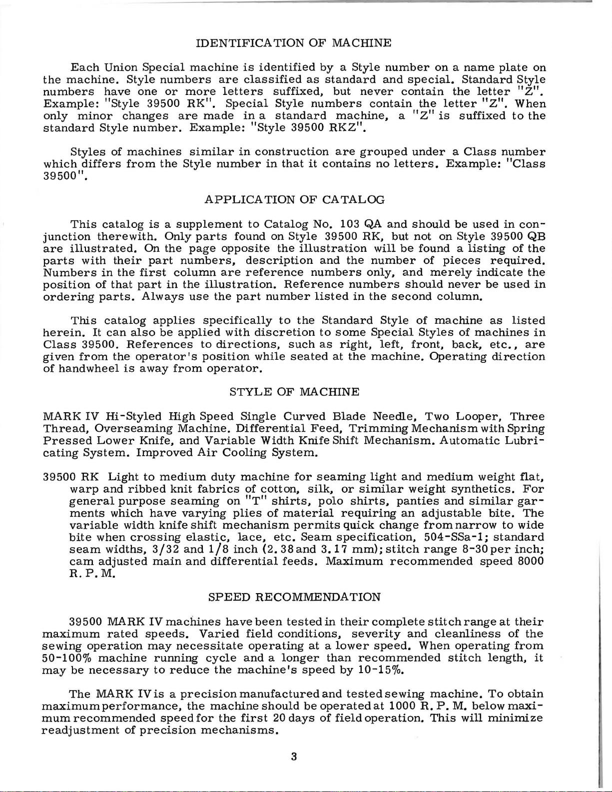
IDENTIFICATION
OF
MACHINE
Each
the
machine.
numbers
Example:
only
minor
standard
Styles
which
39500
differs
11
•
This
junction
are
illustrated.
parts
with
Numbers
position
ordering
This
herein.
Class
given
of
39500.
from
handwheel
Union
Style
have
"Style
changes
Style
number.
of
machines
from
catalog
therewith.
their
in
the
of
that
parts.
catalog
It
can
also
References
the
operator's
is
Special
machine
numbers
one
or
more
39500
RK".
are
made
Example:
similar
the
Style
APPLICATION
is a supplement
Only
On
the
part
first
part
Always
applies
be
page
numbers.
column
in
the
use
applied
parts
illustration.
specifically
to
position
away
from
operator.
is
identified
are
classified
letters
Special
in a standard
"Style
in
construction
number
to
found
opposite
description
are
reference
the
part
with
discretion
directions.
while
suffixed.
Style
39500
in
that
OF
Catalog
on
Style
the
illustration
Reference
number
to
the
such
seated
by a Style
as
standard
but
numbers
machine.
RKZ".
are
it
contains
CATALOG
No.
103
39500
and
the
numbers
listed
Standard
to
some
as
right,
at
number
and
never
contain
grouped
no
QA
and
RK.
will
number
only.
numbers
in
the
Style
Special
left,
the
machine.
on a name
special.
contain
the
letter
a "z"
is
under a Class
letters.
Example:
should
but
not
on
be
found a listing
of
pieces
and
merely
should
second
of
machine
column.
Styles
front,
Operating
Standard
the
suffixed
be
used
Style
never
of
machines
back,
plate
letter
"Z".
to
number
"Class
in
39500
of
required.
indicate
be
used
as
listed
etc.,
direction
on
Style
"Z".
When
the
con-
QB
the
the
in
in
are
MARK
IV
Thread,
Pressed
cating
39500
System.
RK
warp
general
ments
variable
bite
seam
cam
R.
P.M.
39500
maximum
sewing
operation
50-100%
may
be
necessary
Hi
-Styled
Overseaming
Lower
Knife,
Improved
Light
and
to
ribbed
purpose
which
when
widths.
adjusted
MARK
rated
have
width
crossing
3/32
main
IV
speeds.
knife
may
machine
running
to
High
Machine.
and
Air
medium
knit
fabrics
seaming
varying
shift
elastic,
and
and
machines
Varied
necessitate
reduce
STYLE
Speed
Single
Differential
Variable
Cooling
duty
machine
on
plies
mechanism
lace,
1/8
inch
differential
SPEED
have
cycle
the
machine's
OF
MACHINE
Curved
Width
Knife
Blade
Feed,
Shift
Trimming
System.
for
seaming
of
cotton,
"T"
shirts,
of
etc.
(2.
silk,
material
permits
Seam
38
and
feeds.
or
polo
requiring
quick
specification,
3.
17
Maximum
RECOMMENDATION
been
field
operating
and a longer
tested
in
conditions.
at a lower
than
speed
their
by
Needle,
Mechanism.
light
similar
shirts,
and
weight
panties
an
change
mm);
stitch
recommended
complete
severity
and
speed.
recommended
10-15%.
Two
Looper,
Mechanism
Automatic
medium
synthetics.
and
adjustable
from
narrow
504-SSa-1;
range
stitch
8-30
range
cleanliness
When
operating
stitch
with
weight
similar
bite.
standard
per
speed
at
length,
Three
Spring
Lubri-
flat,
For
gar-
The
to
wide
inch;
8000
their
of
the
from
it
The
MARK
maximumperformance,
mum
recommended
readjustment
IV
is a precision
speed
of
precision
the
machine
for
the
mechanisms.
manufactured
first
should
20
be
days
3
and
tested
operated
of
field
sewing
at
1000
operation.
machine.
R.
P.M.
This
below
will
To
obtain
maxi-
minimize
Page 4
OILING
CAUTION!
filled
straight
should
sight
gauge
main
when
no
It
have
denotes
number,
in
size
packaged
before
mineral
be
Machine
gauge
lines
Machine
reservoir
To
maintain
operating
case
is a magnetic
thousandths
should
The
oil
entered
Each
the
stamped
number
used.
on
when
is
drain
the
Union
kind
represent
and
sold
Oil
was
beginning
oil
of a Saybolt
is
filled
front
machine
automatically
filled.
maximum
continuously,
oil
screw
crank
Special
of
of
an
of
remain
plug
shank,
on
the
inch,
by
Union
with
machine.
Check
screw
designed
the
drained
to
operate.
oil
is
stationary.
lubricated.
oil
recommended
the
in
machine
is
case.
needle
needle
It
point,
midway
complete
Special.
from
Oil
viscosity
at
spring
Red
daily
oil
must
located
to
accumulate
should
NEEDLES
has
both a type
length,
shank,
between
symbol
machine
capacity
cap
bulb
on
No
before
speed
for
more
at
back
be
removed
groove,
denotes
of
90
in
oil
oiling
the
be
changed
possible
shank
which
when
and
than
of
and
largest
shipped,
of
Class
to
125
seconds
top
cover.
levelindicator
is
necessary,
morning
serviceability
at
one
year.
machine
foreign
and
cleaned
size
finish
and
is
and
diameter
eye.
given
so
39500
Oil
should
start;
least
number.
every
near
on
bottom
materials
periodically.
other
Collectively,
the
reservoir
is
at
100
level
other
add
oil
of
this
six
The
details.
of
blade,
label
si8-
ounces.
Fahrenheit
is
checked
show
than
as
equipment
months.
edge
which
type
measured
of
all
must
between
keeping
required.
of
base.
may
number
The
size
type
and
needles
be
A
at
In
Class
needle
blade,
is
available
To
sample
on
label.
Selection
should
Success
of
needles
putation
more
Fig.
direction
No.
Again
left,
position,
nut.
than
Release
1)
21388
turn
To
insert
Return
39500
for
Style
standard
in
have
needle,
A
complete
pass
freely
in
packaged
for
producing
three
pressure
and
swing
until
AU,
handwheel
replace
needle
turn
presser
machines
39500
length,
sizes
needle
of
the
needle
needle,
handwheel
022, 025,
orders
or
the
proper
through
operation
under
-quarters
presser
is
furnished
until
in
holder
arm
use a curved
RK
is
Type
single
type
and
order
needle
needle
our
highest
of a century.
on
presser
arm
at
its
with
needle
leave
until
(U)
154
GAS.
groove.
027,
promptly
would
of
brand
CHANGING
lowest
needle
until
holder
to
position;
029,
size
size
Union
quality
machine,
read:
eye
foot
(U)
is
it
number
is
name,
out
point
at
holder
rests
is
blade
struck
032,
and
"1000
determined
in
order
Special
needles
by
turning
of
high
again
re-lockpresser
needle.
It
has a round
groove,
036, 040,
accurately
should
Needles,
machines
~
in
NEEDLES
position.
of
travel.
loosen
position;
at
high
against
at
by
to
produce
materials
presser
Using
needle
position
stop
its
low
The
shank,
spotted,
044,
filled,
be
forwarded.
Type
size
can
,
which
foot
Turn
hexagonal
clamp
withdraw
pin.
point
foot
standard
round
chromium
049,
an
of
thread
a
good
be
and
release
handwheel
and,
Keeping
of
release
054,
empty
Use
154
GAS,
stitch
securetd
is
backed
workmanship
nut
about
needle.
with
travel;
recommended
point,
used.
bushing
in
socket
the
needle
then
bushing
curved
plated
060.
package,
description
Size
027".
Thread
formation.
only
by
by a re-
(AG,
operating
wrench
1/4
turn.
flat
to
in
tighten
(AG).
and
a
use
for
the
this
4
Page 5
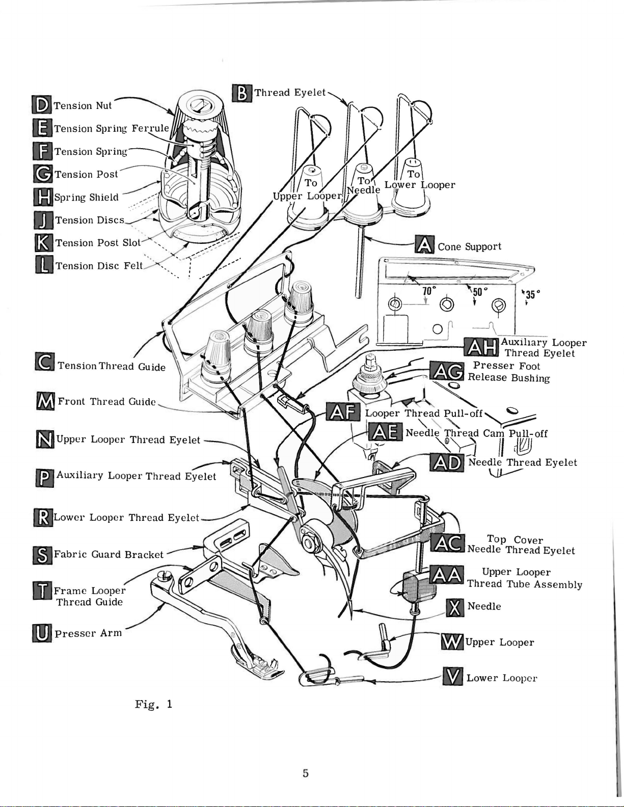
[i
ZJ
Tension
Front
Thread
Thread
Cone Support
Guide
Guide
~Upper
(3Lower
DFramc
Thread
m
Presser
Looper
Looper
Looper
Guide
Arm
Thread
Thread
Fig.
Eyelet
Eyelet
1
..
Needle
Thread
Lower
Top
Upper
Looper
._..._
~Upper
Cover
Thread
Looper
Tube
Looper
Eyelet
Assembly
5
Page 6

THREAD
STAND
After
t
hrough
eyelet.
hole
of
from
to
hole
(J).
(M).
back
front.
from
through
Only
are
placed
It
will
quence
third.
Before
ting
direction
by
turning
position.
Be
tension
thread
the
back
The
needle
tension
to
through
back
tension
parts
in
simplify
of
threading
beginning
presser
sure
threads.
discs
comes
hole
thread
front.
the
to
involved
their
until
(J)
and
of
and
guide
The
middle
front.
post
relative
the
the
to
needle
foot
as
in
from
thread
upper
(C)
lower
hole
All
three
slot
(K)
in
threading
positions
threading
lower
thread.
(X)
is
release
they
come
diagonal
cones
eyelet
looper
from
looper
on
(B),
threads
front
thread
from
threads
in
tension
THREADING
are
for
of
this
looper
swing
at
high
bushing
from
slots
(K)
cone
then
to
is
front
to
then
post
shown
clarity.
machine
first.
cloth
plate
position.
(AG)
the
in
tension
support
down
are
then
back.
threaded
back.
continue
(G)
and
in
threading
to
upper
open.
release
and
tension
(A,
through
threaded
and
then
through
and
on
follow
looper
swing
thread
posts
Fig.
1),
the
through
finally
between
through
diagram
the
second.
turn
hand
pressure
presser
guide
(G).
it
is
brought
front
the
hole
through
the
upper
through
the
tension
front
thread
the
lower
hole
the
(Fig.
recommended
and
the
wheel
on
arm
(C).
in
presser
(U)
are
of
thread
upper
hole
back
lower
discs
guide
1).
Part
se-
needle
opera-
foot
out
between
up
s
of
Double
(M.
Fig.
front.
from
Lead
Then
right
thread
handwheel
left.
be
then
threaded
Thread
turn
handwheel
through
eyes
front
of
of
upper
assembly
tube
thread
assembly
through
CAUTION!
passing
from
end
1).
Lead
lead
to
left.
behind
in
operating
thread
easily
upper
auxiliary
looper
looper
(AA),
upper
tube
of
thread
thread
thread
NOTE:
fabric
through
if
looper
until
looper
thread
lead
(AA).
Be
assembly
TO
and
through
guard
direction
both
tweezers
TO
thread
point
thread
thread
pull-off
thread
Pull
looper
sure
upper
THREAD
lead
through
both
Thread
(S)
eyes
are
THREAD
through
of
upper
eyelet
(AF).
under
thread
eye
from
looper
to
upper
TO
THREAD
THE
it
through
auxiliary
eyes
must
and
until
heel
from
in
left
THE
looper
eyelet
(N)
from
After
neck
out
bottom
front
looper
LOWER
looper
of
lower
pass
through
of
left
hand.
UPPER
left
eyelet
(P)
from
left
pulling
of
top
cover
to
thread
eye.
THE
LOOPER
the
right
thread
looper
in
front
frame
lower
to
right.
LOOPER
of
(W)
is
back
to
right.
casting
of
tube;
back.
is
under
NEEDLE
eyelet
oflooper
looper
looper
Left
front
all
the
to
Note:
up
upper
push
lower
of
eyelet
thread
thread
thread
(V)
eye
thread
way
front.
Thread
and
tube
front
(AH)
eyelet
is
all
of
lower
guide
left.
then
looper
down
down.
looper
thread
from
(R,
pull-off
guide
the
way
looper
(M).
Lead
through
must
thread
through
then
thread
back
Fig.
(T).
pass
guide
to
1)
(AF).
Turn
to
the
can
Then
thread
both
in
tube
thread
insert
when
Thread
handwheel
Insert
(AD).
under
thread
needle
in
needle
eyelet
thread
operating
thread
neck
of
(AC).
direction
from
top
cover
Thread
through
right
casting;
needle
middle
until
to
left,
from
eyelet
needle
throu
then
front.
6
of
(X,
gh
down
front
Fig.
both
through
thread
1)
eyes
is
of
hole
guide
at
its
needle
highest
in
top
(M).
thread
cover
Then
turn
position.
eyelet
needle
Page 7

The
tension
stitch
amount
nuts
(D,
formation.
of
Fig.
tension
1).
Tension
on
the
THREAD
needle
on
threads
TENSION
and
looper
should
threads
be
only
is
regulated
enough
to
by
secure
knurled
proper
Sufficient
ly
should
or
decrease
lock
ing
screw
pressure,
adjusting
(A).
locking
1/32
face
nut
(C).
nut
With
nut
inch
of
Feed
be
(A,
has a right
loosening
screw
presser
to
adjusting
eccentrics
approximately
feed
of
chine
39540
stitches
eccentric
B-10.
obtainable
will
b - c:;hipped
PRESSER
presser
maintained.
amount
Fig.
(B)
2)
has
foot
(C)
so
that
1/16
inch(.
screw
12
stitches
is
No.
Minor
numbers
FOOT
foot
pressure
Should
of
pressure
and
turn
hand
decreases
been
resting
its
under
79
(B).
used
in
per
39540
when
with
above
PRESSURE
it
be
on
adjusting
thread
so
pressure.
properly
on
surface
to
1. 59
Set
FEED
Style
39500
inch.
B-12,
using
of
while
the
that
combination
to
feed
necessary
presser
screw
tightening
When
set,
tighten
throat
plate,
is
mm)
cap
(D)
from
against
ECCENTRICS
RK
It
will
that
part
symbol
eccentric.
work
to
foot,
(B).
uniform-
increase
loosen
Adjust-
increases
pressure
lock
position
approximately
the
top
sur-
locking
machines
be
noted
of
the
have
that
differentialfeed
indicate
Unless
of
eccentrics.
nut
been
selected
the
part
approximately
otherwise
Fig.
to
number
eccentric
the
specified,
2
produce
of
main
is
No.
number
rna-
of
stitches
and
with
Generally
produced;
direction
Fig.
the
cloth
speaking,
of
stretch
3
plate
main
of
under
16,
100.
Additional
an
to
12
cloth
lower
quence:
CAUTION:
the
stud
(C)
differential
(left
hand)
material
Following
No.
18,
20, 22, 24, 26, 28,
Only
eccentric
indicate
".
ASSEMBLING
Before
plate,
knife
CLOTH
cloth
and
plate
cloth
(right
feed
being
stitch
39540
two
B-4,
eccentrics
eccentrics
use
No.
number
assembling
fabric
holder
PLATE
When
removing
stud
plate
hand)
eccentric
sewn,
feed
is
or
type
number
feed
5, 6, 7, 8,
eccentric
selected
of
9,
30, 32, 34, 36,
are
supplied
may
be
ordered
39540 B with a minor
of
stitches
AND
ADJUSTING
and
guard,
assembly,
REMOVAL
locking
screw
desired.
adjusting
chip
guard,
then
the
cloth
screw
(D),
follow
AND
(B)
assembled.
determines
in
relation
operation.
eccentrics
are
10, 11, 12, 13,
40,
with
each
separately.
number
Example:
SEWING
sewing
upper
this
PARTS
parts,
knife
suggested
ASSEMBLY
plate
and
(A,
lift
Fig.
up
number
to
degree
available
14,
50,
60,
machine.
To
order
suffixed
"39540
remove
assembly,
3)
loosen
cloth
plate
15,
70,
B-
se-
7
Page 8

point
bled
rear.
stud
In
assembly,
of
removing
to
the
Stud
to
the
CLOTH
machine
locking
screw
PLATE
the
cloth
allplay
with
screw
(D)
so
REMOVAL
plate
and
the
flat
(B)
is
that
only
screw
yet
turn
and
tightened
the
AND
and
in
"V"
cloth
ASSEMBLY
the
cloth
clothplate.
slot
of
the
securely
plate
will
plate
The
cloth
which
turn
(Continued)
stud
are
cloth
plate
plate
stud
collapses
when
opening
tightened
is
then
(C)
towards
the
body
or
to
the
assem-
the
of
the
closing.
front
With
per
(Fig.
have
Fig.
With
end
Insert
lower
point
6),
lower
Now
13).
throat
of
needle
Fig.
lower
looper
1/8
inch
using
assemble
looper
looper
plate
4
(A.
slot.
looper
at
left
(3.17
gauge
deflecting
differential
Fig.
When
(A,
end
mm)
SETTING
4)
assembled
needle
1/2
align
move
clamp
tighten
laps
looper
pull-off
driving
Fig.
of
its
from
No.
21225-1/8.
needle.
(front)
THE
is
inch
needle
needle
screw
clamp
If
needle
looper
thread
screw.
arm.
6)
into
stroke,
center
Tighten
feed
at
(12.
bar
set
of
high
NEEDLE
in
position,
position,
70
mm)
or
set
driving
(C).
After
screw
thread
thread
pull-off
be
(B).
loo-
needle
Do
not
nut
(C).
dog
(A,
above
the
height
arm
needle
(C)
cam
pull-off
back.
sure
to
needle
needle
throat
(B.
and
remove
pull-off
(B).
When
take
should
point
plate
above
Fig.
has
been
(A,
separate
retightening
up
end
center
should
the
4)
by
set
throat
Fig.
play
(Fig.
throat
loosening
properly,
plate.
5)
by
in
in
the
be
set
4).
To
plate,
over-
moving
looper
needle
SETTING
Set
rear
possible,
looper
in
inch(.
is
to
After
differential
or
position
051-.102
no
interference
needle
this
THE
needle
without
movement
to
deflect
mm).
Fig.
without
setting
feed
dog.
REAR
guard
interfering
of
lower
needle
Screw
between
6
touching.
make
sure
NEEDLE
(A,
Fig.
with
knife
forward . 002-.
(B)
rear
Screw
there
GUARD
7)
holder,
is
used
needle
Now
looper
into
springs
another.
SETTING
Assemble
When
guard,
(D)
is
as
either
to
guard
SETTING
finish
moves
the
needle
forward
002-.004
lower
set
is
used
no
interference
high
lower
but
set
looper
front
as
still
004
rear
and
lower
to
THE
front
to
needle
lower
THE
the
scarf
from
inch(.
FRONT
is
needle
adjust
looper.
LOWER
looper
right,
(A,
rear
051-.102
needle
springing
guard
and
between
Fig.
guard.
LOOPER
adjustment.
its
point
Fig.
NEEDLE
needle
guard
as
set
8)
close
front
needle
5
Make
should
until
guard
mm).
GUARD
(C.
needle
as
needle
guards
sure
As
be
the
needle
surface
Fi
g.
off
possible
guard.
there
lower
set
7).
back
and
8
Page 9

SETTING
THE
UPPER
LOOPER
Insert
holds
in
or
holder
Screw
in
the
shank
holder
As
looper
mm)
upper
upper
out,
into
(C,
looper
or
upper
Fig.
shaft.
extends
(Fig.
Fig.
the
8
upper
should
clearance.
turned
9)
Locate
1/32
9).
pass
looper
in
its
around
looper
on
upper
to
end
should
shank
tween
adjusting
upper
looper
looper
to
.
002
ance
looper
behind
(A,
holder.
shaft,
clamp
1/16
When
of
slightly
Be
the
to . 004
(Fig.
moves
the
Fig.
its
holds
looper
inch(.
the
its
stroke,
be
set
sure
heel
looper
looper
around
point
left
of
lower
9)
in
and
permits
shank.
if
it
is
the
in
79
upper
to
back
there
of
looper
shaft
to
the
(.
051
10).
toward
its
holder.
it
Insert
not
already
upper
its
to
1. 59
looper
holder
mm)
looper
upper
position
of
vertical
is a clearance
and
holder
and
by
its
shank,
cross
lower
looper
to . 102
the
top
looper
head
Screw
to
be
upper
so
above
is
at
looper
upper
casting.
in
or
turning
set
lower
mm)
of
its
with
pushed
looper
in
place.
holder
that
the
holder
looper
(Fig.
out
upper
looper
eye
clear-
stroke,
(B)
the
the
right
9).
be-
By
of
the
with
1/64
to
the
1/32
heel
inch(.
Fig.
of
7
the
40
upper
to . 79
Next,
of
its
travel;
spect
to
essary,
Figure
For
creased
looking
mension
left,
it
out
may
slightly
needle
do
11
represents
example,
by
from
is
of
be
to
Fig.
turn
handwheel
check
and
it
by
moving
turning
left
increased
upper
looper
necessary
maintain
10
until
dimensions
throat
the
plate
the
correct
upper
31/64inch02.30
end
upper
of
by
looper
machine;
pulling
shaft.
to
the
turn
condition
upper
When
quickly
when
needle
looper
as
upper
eye
(Fig.
Check
and
needle
upper
looper
end
11,
looper.
a
of
machine.
12.
upper
of
(Fig.
looper
upper
11).
looper
dimensional
mm)
holder
5/32
upper
After
these
looper
shown
the
correct
follows:
looper
should
12).
setting
on
needle
pull
short
distance
is
at
looper
If
holder
point
resetting
(A,
setting.
dimension
counterclockwise
inch
looper
(3.
holder
changes
around
in
Fig.
10.
setting
As
upper
eye
centers
be
about
to
avoid
interference
downstroke.
looper
out
counterclockwise,
Reset
to
maintain
the
Fig.
97
are
its
level
of
left
with
is
nec-
is
mm)
to
made
shank
is
obtained,
looper
on
with
its
end
re-
11).
indi-
the
is
moving
the
needle,
top
between
If
needle
holder
dimensions
it
can
bottom
surface
upper
rubs
slightly
looking
of
Fig.
be
to
the
and
Figs.
9
checked
the
r i
of
of
upper
looper
back
rotate
from
ght,
the
of
left
10,
9
Page 10

ma
Now
assembl
in
(back) feed dog
e di
(B)
SETTING
fferential
and
chaining
dogs
(A
faces
This
teeth
ble
be
can
with a straight
throat
leveled
rotating
This
pin
of
both
(front)
and
of
teeth
be
feed
raises
feed
THE
feed
B,
checked
plate.
with
tilting
bars
feed
Fig.
lay
Feed
throat
or
lowers
at
FEED
dog
(A,
dog
(C).
13)
so
in
the
by
sighting
edge.
dogs
plate
adjusting
the
same
DOGS
Fig.
Set
the
same
Now
should
surface
the
back
time.
13),
the
top
sur-
plane.
across
assem-
pin
if
not
differential
now
by
(D).
end
already
and mai
in
plac
e,
n feed
nch
i
so
Fig.
(1.
19
its tee
11
mm)
th
are level
above
dogs
teeth
plate.
tilting
set
so
throat
with
The
should
first
main
that
top
main
appear
Screw
adjusting
and
teeth
plate
of
at
throat
and
be
set
level
above
(E,
Fig.
pin
differential
are
approximately
high
point
plate
Fig.
SETTING
differential
at
the
the
13)
locks
in
place.
feed
of
travel.
when
feed
13
THE
feed
time
throat
feed
Now
dogs
3/64
Set
is
at
top
LOWER
chaining
of
its
KNIFE
Fig.
feed
travel.
12
dog
(C)
Fig.
14
Replace
(A.
Fig.
throat
gonal
is
plate
head
spring
adjustment
Lower
tightening
port
bracket.
pin
for
the
be
locked
ed
against.
lower
14)
should
surface.
screw
pressed
is
knife
screw
cloth
with
lower
10
knife
be
Adjustments
which
against
necessary
may
(B)
and
Because
plate
nut
(C)
knife
even
holder assembly.
set
with
cutting
are
holds
when
be
screw
latch
lower
upper
width
secured
locking
(B)
spring.
when
knife,
nut
also
screw
holder.
edge
made
knife.
of
trim
in
any
(C)
serves
it
Lower
flush
with
Lower
so
no
is
position
against
should
is
not
knife
with
hexa-
knife
lateral
changed.
by
sup-
as
latch
always
tighten-
Page 11

SETTING
THE
UPPER
KNIFE
Replace
setting
At
bottom
1/64
be
set
inch
down
After
tightened
when
upper
Loosen
move
knives
obtaining
operator's
upper
position
Standard
upper
nut
(E)
of its
(.
40
against
upper
to
lock
knife
SETTING
set
{E
the
standard
position
seam
to
hold
stroke,
mm)
knife
upper
is
THE
screws
and
and
width
knife
assembly.
clamp
front
below
the
upper
has
been
knife
replaced.
VARIABLE
{A
and
F)
by
pushin~
3/32
while
seated
tighten
or
constant
(F)
cutting
cutting
knife
set
holding
B,
or
1f8
set
screws
in
its
edge
and
for
WIDTH
Fig.
down
inch
at
the
trim
Clamp
most
edge
of
slightly
proper
block
15)
{2.
machine,
(A).
line.
upper
clockwise
of
upper
lower
{J)
KNIFE
on
on
pawl
38
This
knife.
back
width
in
place.
pawl
or
knife
knife
from
of
SHIFT
shaft
lever
3.
17
rotate
will
(D,
Fig.
position
should
The
trim,
This
chain
the
against
extend
cutting
screw
will
MECHANISM
stop
{G)
mm)
collar
collars
to
position
seam
{C)
position
14)
guard
edge.
{H)
simplify
{C
width.
clockwise
the
knives
in
position,
upper
not
less
{G)
should
resetting
and
desired
From
knife.
than
should
D)
and
for
the
to
for
the
be
its
Next,
down
tighten
lever
Screw
for
holding
NOTE:
of
the
on
lever
set
{G)
is
This
cutting
move
{G)
screws
pulled
{H)
holds
the
machine
knives
knives
and
{B).
downwardly,
the
tension
from
to
the
rotate
This
variable
post
is
designed
the
right
to
collar
will
position
when
shift
mounting
to
constant
Fig.
obtain
{D)
crossing
mechanism
bracket.
give a maximum
15
the
variable
counterclockwise
the
knives
elastic,
in
trim
11
line
to
the
for
trim
the
etc.
place,
of
5/64
variable
line
to
its
variable
while
inch
desired
upper
screw
{1.
trim
position
trim
98
mm)
line.
by
pushing
line
(J)
when
is
used
travel
and
Page 12

SETTING
THE
STITCH
LENGTH
withdraw
during
extraction.
If
eccentrics
addition
Fig.
17)
move
Then
nut
continue
Fig.
16
eccentrics.
to
removing
from
(G)
shaft
and
as
SETTING
It
may
are
unusually
nut
(E),
it
feed
driving
originally
THE
PRESSER
Length
of
feed
16)
actuates
eccentr
In
facing
key.
To
washer
operating
the
front.
with
be
necessary
tight
(C)
and
may
be
connection
suggested.
eccentrics
ic (B)
assembling
each
Tighten
change
(D)
direction
Using
machine,
fitting,
washer
helpful
FOOT
of
stitch
main
actuates
other.
nut
feed
from
hooked
reach
to
move
(D,
to
re-
(H).
used.
(rear)
the
Be
(C)
end
until
in
securely.
is
determined
Outer
feed
dog;
the
differential
feed
eccentrics,
careful
eccentrics,
of
shaft
key
slot
eccentric
behind
handwheel
by
(left)
eccentric
while
not
to
remove
(E).
Turn
in
eccentric
extractor
eccentrics
back
the
the
(front)
be
sure
damage
nut
handwheel
(F),
as
and
forth
combination
(A,
Fig.
inner
(right)
feed
hubs
shaft
(C)
dog.
are
or
and
in
is
toward
supplied
shown
and
slightly
With
(U,
Fig.
er
foot
flat
on
in
presser
needle
be
flat
plate
nut
(F).
chip
Assemble
needle
in
1)
intosewingpositionandsetthepress-
to
align
throat
foot
hole
in
on
the
slots
by
Re-assemble
guard,
turn
the
high
needle
plate.
must
throat
throat
shifting
Fig.
handwheel
presser
position,
holes
The
front
be
aligned
plate.
plate.
the
18
the
foot
swing
(front
edge
with
It
is
If
necessary,
foot
lifter
chip
until
to
presser
presser
and
of
needle
front
also
guard,
upper
arm.
arm
back)
hole
edge
important
presser
lever
loosen
screw
shaft
to
collar
The
the
collar
presser
er
foot
Adjust
presser
looper
should
mm)
free
presser
should
fabric
knife
and
of
that
shaft
(H,
collar
(G)
and
the
left
screws
foot
(B)
arm
does
release
lifter
foot
can
will
permit;
be
from
motion
foot
be
made
guard
assembly
the
foot
Fig.
screws
then
or
and
lifter
secure
not
bushing
lever
be
1/16
of
begins
with
and
reaches
bottom
can
shift
right
clamp
lever
bind
raised
then
to
foot
to
screw
cloth
be
realigned
18).
(B,
the
as
screw.
arm
the
and
is
stop
lock
1/8
lifter
rise.
of
1
7
the
move
18)
Fig.
To
Fig.
foot
required.
(A,
shaft.
rise
unlocked.
screw
no
higher
the
nut
inch
(1.
lever
Th
is
(E)
and
plate.
its
To
highest
presser
with
throat
the
shaft,
and
clamp
lifter
lever
Retighten
Fig.
Be
sure
when
(C)
than
(D).
59
18)
press-
so
upper
There
to
before
adjustment
locked
assemble
position.
foot
and
the
that
3.
17
the
with
12
Page 13

Be
thread
tensions
horizontal
ly,
without
tongue
freely.
sure
machine
and
in
presser
Swing
light,
the
is
set
middle
foot
in
presser
STARTING
threaded
looper
of
their
place,
foot
TO
according
thread
front
to
make
into
position,
OPERATE
to
eyelets
to
back
sure
insert
threading
(N
and
locations.
chain
forms
material
diagram
R,
Fig.
Operate
and
and
(Fig.
1)
approximately
1).
machine
moves
sew
off
slowly.
With
slowstitch
While
needle
be
just
if
excessive
position
just
contacts
It
tor)to
With
back
its
mm)
far
most
distance
should
looper
While
portion
looper
the
tension
eyelet
sewing
thread
tight
needle
is
desirable
delay
material
enough
rearward
be
set
(V)
heel
of
lower
thread
(R)
down,
is
enough
thread
thread
needle
slightly,
so
behind
with
eyelet
sewing
comes
while
on
material,
drawn
to
is
thread.
to
adjust
the
under
thread
position.
needle
its
eyelet
on
looper
off
lower
keeping
NEEDLE
on
needle
feed
chain
pulled
eyelet
the
tightening
LOWER
presser
is a little
Looper
thread
approximately
at
the
time
material,
thread
upper
looper
the
same
UPPER
check
down
off
on
the
(AD,
Fig.
needle
of
LOOPER
foot,
slack
thread
cam
lower
check
should
looper.
thread
amount
LOOPER
THREAD
needle
stroke.
stitch
up
tongue.
stroke.
1)
so
thread
the
needle
THREAD
set
lower
when
pull-off
pull-off
1/8
looper
drawing
be
drawn
To
increase
is
on
upper
of
THREAD
CONTROL
thread
At
top
control
of
Stitch
With
that
needle
eyelet
well-forward
thread.
CONTROL
looper
looper
(AF)
(AE).
inch
(3.
is
at
off
of
through
amount
looper,
pull-off
CONTROL
needle
tends
needle
thread
thread
thread
is
Frame
17
mm)
extreme
looper
the
move
action.
as
stroke,
at
pull-off
set
looper
to
left
thread
tension
of
thread
follows:
to
pull
bottom
cam
(toward
eyelet
about
1/3 2 inch
thread
the
right
end
as
drawn
lower
Usually
thread
down
of
pull-off
the
(R,
(AF)
guide
of
its
follows:
before
looper
should
slightly
stroke,
(AE)
opera-
Fig.
reaches
(. 79
(T)
of
lower
travel.
lower
through
thread
all
1)
A
Before
three
will
not
During
draw
is
drawn,
pull-off
To
Fig.
to
1)
have
If
all
end
that
it
to
form
edge.
The
being
ble
without
should
purl
is
tensions
markedly
upper
upper
reaches
move
should
slightly
it
becomes
play
is
higher
near
needle
sewn.
be
increased
pulled
proceeding
to
give a normal
affect
needle
looper
down
thread
looper
its
most
the
purl
be
raised
more
necessary
in
needle
over
top
edge.
thread
In
general,
causing
needle
as
too
far
to
adjust
the
stroke,
through
thread
rearward
more
keeping
pull-off
drive
throat
If
upper
tension
lower
long
over
the
upper
looper
appearing
purl.
forward
the
tension.
will
have
position.
POSITIONING
under
on
to
shaft
plate
the
upper
move
before
than
looper
the
edge,
same
thread
looper
recommended
is
THREAD
required
looper
thread
as
the
thread
to
be
elasticity
top.
thread
stitch.
stroke
Moderate
of
When
almost
THE
all
PURL
both
amount
than
thread
pull-off
tightening.
too
low,
the
TENSIONS
is a function
tension
pulled
down.
of
the
eyelet
looper
normal
slack
looper
of
pull-off.
on
lower
If
in
purl
of
should
Upper
chain
(N,
change
thread
amount
taken
thread
thread.
(AF),
upper
Fig.
will
needle
be
increases,
Fig.
pull-off
up
eyelets
Usually
be
looper
11,
the
form
thread
set
as
looper
in
of
as
sure
nearer
high
thread
1)
balance
these
looper
looper
it
to
is
located
purl
and
or
tensions
(AF)
thread
thread
(Nand
is
better
take
will
tend
bottom
material
as
possi-
tension
until
all
will
R,
up
so
the
13
Page 14

14
Page 15

The
that
parts
are
illustrated
used
on
Style
on
the
39500
preceding
RK,
but
not
page
used
and
on
described
Style
39500
below
QB.
represent
the
parts
Those
Styles
Use
this
Reference
descriptions,
Ref.
No.
1
1A
2
3
4
5
6
7
8
9
10
11
12
13
14
15
16
17
18
19
20
21
22
23
24
25
26
27
28
29
30
31
32
33
34
35
36
37
38
39
40
41
parts
39500
Catalog
catalog.
Part
39592
39592
39592
39592
39592
39592
22891
39568
29477
22743
39568
39568
39573
39573
39573
39578
39573
55235
6042
55235
39573
39573
43544
39573
39573
39573
39573
22891
39592
39573
22572
39573
660-264
421
39550
39550
22559
21660
shown
QB
No.
numbers
indicate
No.
AT
AS
AR-5
AR-8
T-3
AP
88
A
E
HR
G
J
X
y
z
u
w
E
A
D
A
v
A
98
T
R
88
p
88
M
u
88
s
93
A
N
D-8
K
J
H
A
and
103
in
phantom
RK.
QA
that
they
view
(Style
are
inside a bracket
are
Leaf
Needle
Looper
Needle
Tension
Tension
Screw,
Screw,
Auxiliary
Upper
Thread
Knife
Chip
Upper
Driving
Upper
Upper
Upper
Knife
Pawl
Pawl
Screw,
Needle
Pawl
Screw,
Knife
"S"
Treadle
Spring
Lower
Screw,
Knee
Spring
Looper
Set
Thread
Spring,
Knife
Support
Guard
Knife
Nut,
Washer,
Locking
Knife
Knife
Screw------------------------------------------
Knife
Regulating
Set
Shaft
Set
Shaft
Set
Lever-----------------------------------------
Screw,
Regulating
Hook,
press
Press
and
bearing
39500
component
Thread
Thread
Thread
Post
Post
for
for
Screw,
Tube
Arm
Screw--------------------------------------Screw---------------------------------------
for
Thread
Screw---------------------------------------
for
Chain, 8 inches
assembly------------------------------------
Cover
Knife
for
QB)
for
---------------------------------------Tension
Tension
Tension
Mounting
Bar-----------------------------------tension
auxiliary
Lower
Support
-----------------------------------------
for
Stop
Support
pawl
pawl
for
lower
Assembly
Looper
Thread
for
Tube------------------------------------
for
thread
Block------------------------------
Guide
Block
Driving
driving
for
driving
Stud,
Washer---------------------------------
Driving
Driving
Driving
Pawl--------------------------------
Collar
shaft
Tension
for
pawl
shaft
Pawl
treadle
---------------------------------------
Pressure
knife
no
reference
all
parts
on
the
parts
post
----------------------------------
for
Bracket---------------------------
of a complete
Description
Plunger-----------------------
Spring------------------------
Spring------------------------
Bracket
bracket-----------------------
lower
thread
Spring
Lever
lever
Arm
Arm
Arm
support
lever
support
chain---------------------------
looper
Thread
Tube
driving
Shaft---------------------------
(not
Assembly------------------
tube------------------------
tube---------------------------
---------------------------
---------------------------
---------------------------
lever------------------------
Spring
Collar
----------------------------
-------------------------------
Release
---------------------------
(203.
Equalizing
holder
shown
numbers,
not
illustrated
picture
-----------------------
Eyelet
lever
----------------------
bracket
Arm
bracket
200
locking
plate
part
thread
-------------------
----------------------
mm)
Spring---------------
on
picture
eyelet---------
----------------
-----------------
------------------
-----------------
long
stud
-------------
are
or
and
have
or
assembly.
for
knee
plate)
common
described
indented
Amt.
------
to
in
Req.
1
1
2
1
1
1
1
1
1
1
1
1
1
1
1
1
1
1
1
1
1
1
1
1
2
1
1
2
2
2
1
1
1
2
1
1
1
1
2
1
1
1
1
1
15
Page 16

,..o
"'
..
'
()
WORLD'S
,..
' l f
FINEST
QUALITY
*
INDUSTRIAL
SEWING
MACHINES
UNION
SPECIAL
facilities throughout
aid
you
in
the selection of
equipment
for your particular
Special representatives
tory
trained
promptly
tion,
there
serve you.
ATLANTA,
BOSTON,
CHICAGO,
DALLAS, TEXAS
LOS ANGELES, CAL.
NEW
PHILADELPHIA,
GA.
MASS.
YORK,
and
and
is
a Union Special Representative to
Check with him
ILL.
N.
Y.
PA.
maintains sales
the
world. These offices
and
are
able
efficiently.
and
service
will
the
right sewing
operation.
service men
to serve
Whatever
Union
are
fac-
your
needs
your loca-
today.
MONTREAL, CANADA
TORONTO,
BRUSSELS, BELGIUM
LEICESTER,
LONDON,
PARIS,
STUTTGART, GERMANY
CANADA
ENGLAND
ENGLAND
FRANCE
Representatives
industrial
and
cities
distributors
throughout
in
the
all
important
world.
CORPORATION
400
N.
FRANKLIN
ST.,
CHICAGO,
ILL.
60610
 Loading...