

Page 1
INDUSTRIAL
SEWING
FINEST
S
TYLES
395
395
395
®
QUALITY
00QW
00RG
00RH
C 0 L U M B I A®
MACHINES
CD
CATALOG
No.
103QW
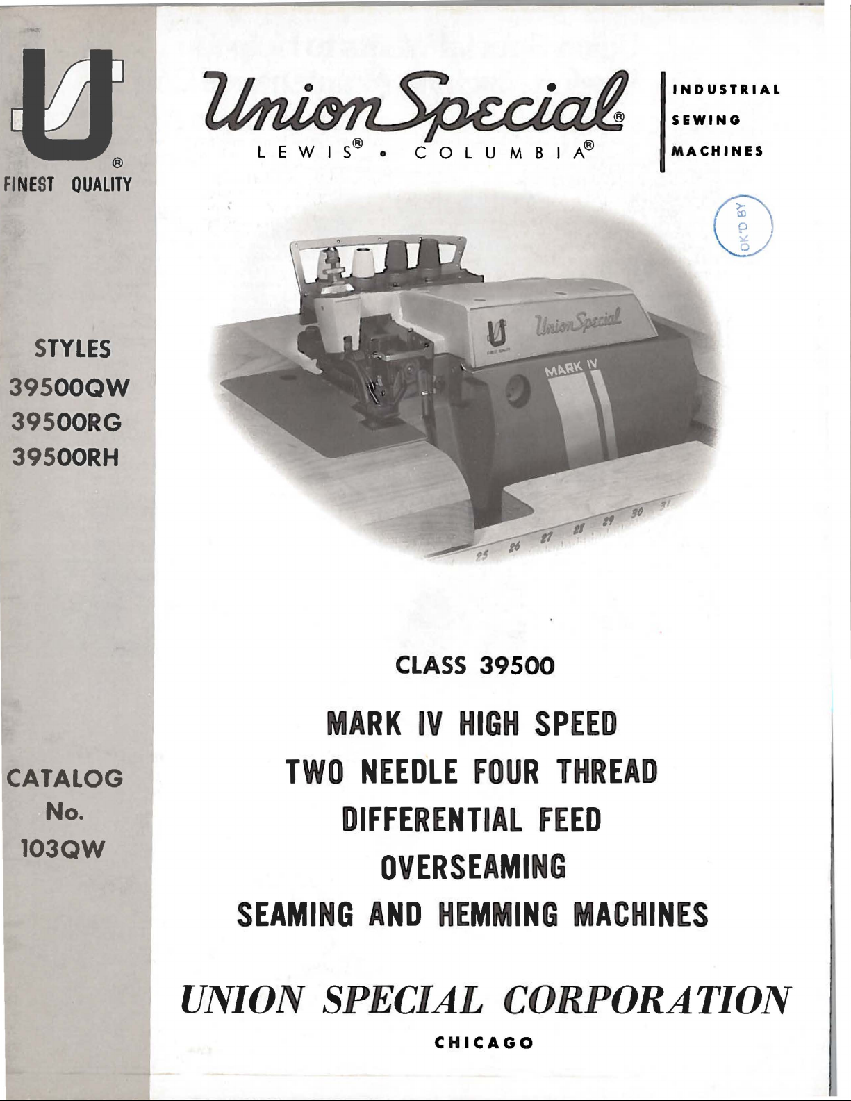
MARK
TWO
CLASS
IV
NEEDLE
39500
HIGH
FOUR
DIFFERENTIAL
OVERSEAMING
SEAMING
AND
HEMMING
UNION SPECIAL
CHICAGO
SPEED
THREAD
FEED
MACHINES
CORPORATION
Page 2
Union Special is offering
reduce
your
system to help spot machines requiring
and a parts inventory system to speed routine repairs.
Machine Maintenance Records
Repair-prone machines
up
your
Union Special suggests two variations
record keeping system using cards provided by
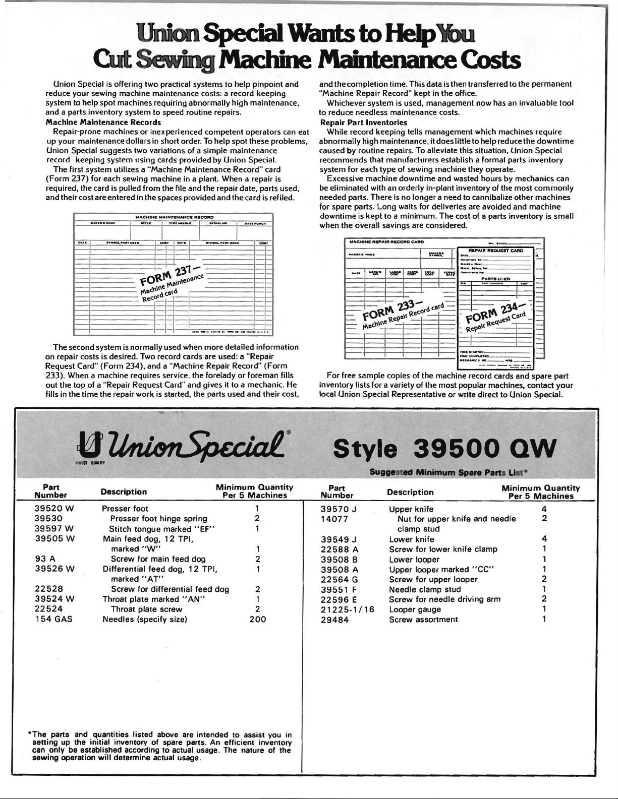
The first system utilizes a "Machine Ma intenance Record" card
(Form
required, the card is
and their cost are entered in the spaces provided and the card is
sewing machine maintenance costs: a record keeping
maintenance dollars in short order. To help spot these problems,
237) for each sewing machine in a plant. When a repair is
IIIIAAI.SN"III
IIIA1&
11"1-..f'A
two
practical systems to help
abnormally
or
inexperienced competent operators can eat
of
a simple maintenance
pulled
from
the file and the repair date, parts used,
MACHINil
MAIHTI"NAHC.
.......
I I I I
...
UIIID
-
""
RICOAD
........
DAR
..
...
IY.._P•Inua~oa
Union
'"
...
.
pinpoint
high
maintenance,
Special.
.
.....
_
refiled.
..
-·
'2,31-
fO'tt~e\Ote!\eo'e
rt-e'"\~e
,efd
\te'of
-
--·
-
The second system is normally used when more detailed information
on repair costs is desired. Two record cards are used: a
Request Card"
233). When a machine requires service, the forelady
out the
fills in the.time the repair
(Form
234), and a "Machine Repair Record"
top
of
a "Repair Request Card" and gives it to a mechanic. He
work
is started, the parts used and their cost,
...
-·
···
"Repair
or
foreman fills
..
(Form
and
to
of
the most
.....
:.
!IIID
'2,'34-
to
by
s\
Union
the permanent
downtime
inventory
mechanics can
commonly
CARD
1
;-
I
~
1-
I=
-·
1-
I=
:
I=
1-
(.etd -
~
I=
I=
I=
I=
Special.
and the completion time. This data is then transferred
"Machine Repair Record"
Whichever system is used, management now has an invaluable tool
to
reduce needless maintenance costs.
Repair
Part
While record keeping tells management which machines require
abnormally high maintenance,
caused
recommends that manufacturers establish a formal parts
system
Excessive machine
be
eliminated with an orderly in-plant inventory
needed parts. There is
for
spare parts.
downtime is
when the overall
Inventories
by
routine repairs. To alleviate this situation, Union Special
for
each type
Long waits
kept
sav
MACHINII RCP'AIR
·-·
...
...
...
_,.
"'1!11
.•
=
fO~e
- rt-ed""
=-
-·
kept
in the office.
it
does little to help reduce the
of
sewing machine they operate.
downtime
no
to a
minimum
ings are considered.
RIICORD
-
t'\
'2,33- d
\te9a\f
and wasted hours
longer a need to cannibalize other machines
for
deliveries are avoided and machine
CAitO
WI"
\te'of
. The cost
~::w
m,..
,efd
-I--
RllJIAIR
.
...
.
I
..........
-
·-·
I
"'"""'
.
OO.•
•·-·-
·-
-
-
fOttt'\
. \teque
_ \tt e\f . .
I .... & I I
fl•
t:CCIM
MI
CHM
of
a parts inventory is small
RllQUUT
.
........
,..
PARTBU
-·-
AMI
D
f'ILniD
ICI
1100--HM.--
-------
For free sample copies
inventory lists
local
Union
for
Special Representative
a variety
of
the machine record cards and spare part
of
the most popular machines, contact
or
write direct
your
Part
Number
39520
39530
39597
22528
39524
22524
"The
setting up the initial
can
sewing operation
w
w
39505
93
39526
w
A
w
w
154
GAS
parts and quantities listed above are intended to assist
only
be established according
Description
Presser
Throat
Needles
will
foot
Presser
Stitch
Main
marked
Screw
Differential
marked
Screw
Throat plate
foot
hinge
tongue
feed
plate
inventory
determine actual usage.
marked
dog, 12 TPI,
"W"
for
main feed
feed
"AT"
for
differential
marked
screw
(specify
of
spare parts. An efficient inventory
to
spring
"EF"
dog
dog, 1 2 TPI,
feed
"AN"
size)
actual usage. The nature of the
Minimum
Per 5 Machines
dog
Quantity
1
2 .
1
1
2
1
2
1
2
200
vou
in
Style
Suggested
Part
Number
39570
14077
39549
22588
39508
39508
22564
39551
22596
21225-1/16
29484
J
J
A
B
A
G
F
E
39500
Minimum
Description
Upper
knife
Nut
for
upper
clamp
stud
Lower
knife
Screw
for
lower
Lower
looper
Upper
looper
Screw
for
Needle clamp
Scr~w
Looper gauge
Screw
upper
for
needle
assortment
§~»are
knife
knife
marked
looper
stud
driving
Pa
rts Uat•
Minimum
and needle
clamp
"CC"
arm
QW
Quantity
Per 5 Machines
4
2
4
1
1
1
2
1
2
1
1
Page 3
(Supplement
Catalog
to
Catalog
INSTRUCTIONS
No.
FOR
103
QW
No.
103
QA)
ADJUSTING
39500
QW
LIST
CLASS
First
AND
OF
Styles
39500
OPERATING
PARTS
39500
RG
Edition
39500
RH
May,
1981
Union
Rights
Copyright@
by
Special
Reserved
1973
Corporation
in
All
Countries
UNION SPECIAL CORPORATION
INDUSTRIAL
Printed
SEWING
CHICAGO
in
U.S.A.
3
MACHINES
Page 4
IDENTIFICATION
OF
MACIDNES
on
the
Style
Each
UNION
machine.
numbers
Example: 11Style
only
ard
Style
Styles
which
minor
differs
changes
number.
of
machines
from
39500".
This
junction
on
Style
opposite
description
reference
tion.
part
This
herein.
Class
given
of
handwheel
catalog
therewith.
39500
the
numbers
Reference
number
catalog
It
can
39500.
from
the
illustration
and
listed
References
is
SPECIAL
Style
have
39500
one
QW".
are
numbers
or
made
Example:
similar
the
Style
is a supplement
QP
Only
are
those
illustrated
will
the
number
only,
numbers
in
the
applies
also
be
applied
operator's
away
from
machine
is
are
more
letters
Special
in a standard
"Style
number
39500
in
construction
in
APPLICATION
to
Catalog
parts
and
be
found a listing
of
pieces
and
merely
should
second
indicate
never
column.
specifically
with
discretion
to
directions,
position
while
operator.
identified
classified
suffixed,
Style
QWZ".
that
numbers
it
OF
used
on
listed
required.
be
used
to
the
such
seated
by a Style
as
standard
but
never
contain
machine, a "Z"
are
grouped
contains
no
letters.
CATALOG
No.
103
QA
and
Styles 3 9500
at
the
of
back
the
of
parts
Numbers
the
position
in
ordering
standard
to
some
as
right,
at
the
of
Styles
Special
left,
machine.
number
and
on a name
sp·::!cial.
contain
the
letter
is
suffixed
under a Class
Example:
should
QW,
this
with
in
that
parts.
of
catalog.
the
be
RG
and
their
first
part
Always
machines
Styles
front,
back,
Operating
the
11 Z 11
to
the
used
RH,
On
part
column
in
the
of
machines
plate
Standard
letter11Z
•
When
stand-
number
"Class
in
con-
but
not
the
page
numbers,
are
ill
us
tra-
use
the
as
listed
etc.,
are
direction
11
in
•
MARK
Thread
Pressed
39500
knitted
jamas,
and
ments
Standard
8-20
speed
39500
baby
materials.
able
514-EFe-1.
(6. 75
feeds.
39500
pockets,
and
cotton,
width
per
speed
IV
Hi
-Styled
Overseaming
Lower
QW
Medium
and
bathing
similar
of
wool,
width
per
inch.
7500
RG
Medium
blankets
Hem
turned
mm).
Maximum
RH
Medium
bathing
similar
wool,
from
inch.
7500
left
Cam
R.
High
Machines.
Knife,
Automatic
to
woven
fabrics
suits,
garments
cotton,
of
Cam
R.
P.
M.
to
heavy
and
is
up
hemming
Standard
Stitch
recommended
to
heavy
suits,
garments
silk
and
needle
adjusted
P.M.
STYLES
Speed,
heavy
duty
house
of
light
silk
seam
from
adjusted
duty
for
similar
turned
scroll
seam
range,
duty
house
of
light
synthetics.
approximately
main
OF
MACIDNES
Two
Curved
Differential
Lubricating
machine
with a modified
dresses,
to
medium
and
left
main
and
machine
children's
synthetics.
needle
differential
for
operations
up
with
the
roll
on
width
6-15
machine
dresses,
to
right
per
speed
medium
Seam
side
from
inch.
7000
for
children's
specification
17
and
differential
Blade
Feed,
Trimming
System,
for
seaming
safety
heavy
17/64
decorative
on
articles
extending
of
presser
left
needle
Cam
R.
P.M.
seaming
weight
f64
inch
Needles,
Improved
stitch.
wear,
weight
Seam
inch
feeds.
hemming
to
adjusted
operations
wear,
woven
(6.
75
feeds.
Two
Loopers,
Mechanism
Air
Cooling
medium
For
ladies'
woven
to
operations
undergarments
and
specification
(6.
75
mm).
Maximum
of
medium
of
medium
the
right
foot.
needle.
Seam
approximately
main
and
on
ladies
and
514-SSa
mm).
undergarments,
knitted
-1.
Standard
Stitch
Maximum
Four
with
Spring
System.
heavy
knitted
Stitch
weight
on
gar-
512-SSa
range,
pa-
-1.
recommended
weight
weight
woven
Adjust-
specification
17/64
inch
differential
coat
linings,
materials
seam
range,
6-15
recommended
of
NOTE:
On
Styles
3 9 500
RG
and
RH,
the
upper
4
looper
thread
is
caught
by
both
needles.
Page 5
SPEED
RECOMMENDATION
39500
maximum
ing
operation
machine
sary
to
The
maximum
commended
justment
CAUTION!
before
mineral
used.
sight
gauge
main
beginning
Machine
gauge on
lines
Machine
reservoir
MARK
rated
running
reduce
MARK
performance,
speed
of
precision
oil
of
when machine
IV
speeds.
may
necessitate
cycle
the
IV
for
Oil
to
Saybolt
is
filled
front
is
automatically
filled.
machines
Varied
and a
machine's
is a precision
the
the
first
mechanisms.
was
drained
operate.
viscosity
with
of
machine.
Check
have
field
operating
longer
speed
machine
20
Oil
oil
is
stationary.
lubricated.
oil
been
conditions,
than
by 10-15%.
manufactured
should
days
of
from
machine
capacity
of
90
at
spring
Red
bulb
daily
before
tested
at a lower
recommended
be
OILING
to
in
and
operated
field
when
of
Class
125
cap
in
on
oil
No
oiling
the
their
severity
operation.
shipped,
seconds
top
level
morning
complete
speed.
stitch
tested
at
1000 R.P.M. below
39500
cover.
is
and
cleanliness
When
operating
length,
sewing
This
so
reservoir
is
eight
at
100°
Oil
indicator
necessary,
start;
stitch
machine.
will
ounces.
Fahrenheit
level
should
add
range
it
minimize
must be
other
oil
at
their
of
the
sew-
from 50-100%
may
be
neces-
To
obtain
maximum
A
should
is
checked
show
than
as
required.
straight
re-
read-
filled
between
keeping
be
at
To
maintain
operating
should
It
have
shank,
the
eye.
on
for
and
Type
154
oil
The
is a magnetic
entered
Each
point,
needle
Collectively,
the
label
Class
the
machines
sizes
No.
GAS
maximum
continuously,
remain
oil
needle
shank,denotes
39500
available
in
drain
screw
the
crank
has
length,
of
all
machines
covered
Round
struck
055/022,
125/049,
recommended
the
machine
plug
screw
designed
case.
both a type
groove,
largest
type
and
needles
use a curved
in
of
the
recommended
shank,
groove,
round
065/025,
140/054,
oil
must
for
more
is
located
to
It
should
and
finish
diameter
size
number
packaged
this
catalog
Description
point,
spotted,
070/027,
150/060.
speed
be
than
accumulate
NEEDLES
size
and
and
blade
needle.
and
changed
one
at
back
be
removed and
number. The
other
of
represent
sold
is
curved
chromium
075/029,
serviceability
at
least
year.
of
machine
possible
details.
blade,
by
needle.
Type 154
and
measured
the
Union
Sizes
blade,
plated
080/032,
every
near
foreign
cleaned
type
number
The
complete
Special.
The
standard
GAS.
standard
and
090/036,
of
this
six
months.
bottom
materials
periodically.
denotes
size
number, stamped
midway
Below
length,
is
between
symbol which
recommended
is
available
100/040,
equipment
In
edge
of
which
the
shank
is
the
description
single
in
110/044,
when
no
case
base.
may
kind
of
on
and
given
needle
groove,
sizes
To
have
needle,
complete
or
order
needle
the
would
type
orders
and
size
read:
promptly
number
"1000
and
accurately
should
Needles,
be
forwarded.
Type 154
5
filled,
GAS,
an
Use
Size
empty
description
090/036".
package, a sample
on
label.
A
Page 6
NEEDLES
(Continued)
Selection
should
Release
(AG,
Fig.
direction
wrench
Again
turn
To
the
left,
in
this
then
tighten
bushing
After
are
threaded
through
through
holes
of
guide
threads
post
(G)
pass
1)
until
No.
21388
handwheel
replace
insert
position,
(AG)
. '
thread
the
center
holes
the
(C)
front
continue
and on
of
proper
freely
pressure
and swing
needles
AU,
needles,
needles
turn
nut.
comes from
through
holes
of
the
front
bar.
to
between
through
through
on
presser
are'at
furnished
until
leave
handwheel
Return
the
back
of
middle
Next
back
tension
front
needle
needle
presser
needles
in
holder
presser
cones
bar
the
bar
it
and
then
thread
size
eye
CHANGING
foot
arm
(U)
their
with
are
needle
until
until
arm
THREAD
on
of
front
from
is
threaded
through
discs
is
determined
in
order
NEEDLES
by
out
lowest
machine,
at
their
holder
they
holder
(U)
to
STAND
cone
support
the
thread
bar.
back
guide
to
(J),
(M).
to
turning
of
position.
point
loosen
highest
at
high
rest
is
position;
eyelet
The
looper
front
through
the
lower
through
by
produce
presser
of
travel.
needle
position
against
again
(A,
Fig.
(B),
and
the
upper
holes
tension
size
of
thread
a good
foot
Turn handwheel
Using
clamp
nut
position.
and
with
stop
pin.
at
its
low
re-lock
threads
then
presser
1),
under
come
through
the
the
holes
from
back
post
slot
used.
stitch
release
in
hexagonal
about
Withdraw
the
Keeping
point
of
foot
needle
middle
from
the
the
two
of
tension
to
front.
(K)
in
Thread
formation.
bushing
operating
socket
1/4
turn.
needles.
flats
to
needles
travel;
release
threads
bar
and
cones,
outside
thread
The
tension
Only
Parts
are
It
quence
Before
direction
turning
Be
the
tension
posts
for
should
the
parts
placed
will
of
threading
beginning
until
presser
sure
discs
different
involved
in
simplify
needles
foot
the
threads,
be
positioned
threads
their
the
lower
to
release
(J)
in
relative
threading
looper
thread,
(X)
as
and
as
threading
are
bushing
they
in
tension
so
the
indicated
positions
of
first,
swing
in
high
come
tension
THREADING
are
shown
these
upper
cloth
position,
in
for
clarity.
machines
looper
plate
release
(AG), and swing
from
the
tension
post
in
slot
post
Fig.
6
(K)
slot
1.
the
second,
open,
presser
thread
in
tension
will
threading
to
follow
and
turn
handwheel
pressure
arm
guide
post
be
at
diagram
the
the
on
(U)
out
(C),
(G).
the
approximate
(Fig.
recommended
needles
in
presser
of
are
TQe
third.
operating
foot
position.
between
tension
1).
se-
by
angle
Page 7

TO
THREAD
LOWER
LOOPER
Double
(R,
Fig.
pull-off
looper
looper
Left
through
eyes
in
assembly
tube
thread
passing
highest
needle
in
through
needle
eye
Turn
of
front
assembly
CAUTION!
Turn
top
cover
end
1)
from
(AF).
thread
(V)
is
of
lower
handwheel
auxiliary
upper
of
looper
(AA),
through
from
handwheel
position.
thread
needle
the
right
thread
of
Lead
guide
all
the
looper
lead
(AA).
upper
Be
tube
Insert
eyelet
hole
eyelet.
thread
right
looper
looper
to
thread
(T).
way
until
thread
thread
thread
Pull
looper
sure
assembly
in
operating
both
(AD),
thread
and
Thread
and
left.
behind
Turn
to
the
can
be
TO
point
thread
eyelet
pull-off
under
thread
eye
upper
to
TO
needle
under
eyelet
the
lead
it
through
NOTE:
fabric
handwheel
left;
THREAD
left
needles
then
threaded
of
upper
eyelet
(N)
(AF).
neck
out
from
looper
upper
THREAD
direction
threads
neck
(AC).
needle
Thread
guard
in
thread
easily
UPPER
looper
(P)
from
After
of
top
bottom
front
thread
looper
THE
of
top
The
thread
from
both
eyes
must
(S)
operating
through
if
LOOPER
(W)
from
left
to
pulling
cover
of
tube;
to
back.
is
eye.
NEEDLES
until
from
cover
right
through
the
front.
of
pass
and
through
direction
both
tweezers
is
all
back
under
needles
right
needle
to
right.
up
casting
push
to
casting;
the
lower
in
front
eyes
are
the
way
front,
NOTE:
upper
and
tube
lower
(X,
left,
and
thread
left
looper
of
eyelet
until
from
in
left
left.
then
Thread
looper
down
down,
looper
Fig.
hole
1)
through
down
should
of
thread
looper
hole
heel
left
hand.
Lead
through
must
thread
through
then
thread
are
both
through
be
the
top
eyelet
thread
of
frame
of
lower
to
right.
thread
both
pass
tube
thread
insert
when
at
their
eyes
threaded
of
holes
cover
7
Page 8

(j]Tension
Nut
IITension
[!]Tension
IIJspring
OTension
~~Tension
II
Tension Disc Felt··
Spring
Post
Shield
Discs
Post
----'
:
~-~
-
/
Slot·. --...
..
riJ
Front
IIJ
Upper
I:JLower
BJFabric
OFrame
Thread
m
Presser
FOR
STYLES
Thread
Looper
Looper
Guard
Looper
Guide
Arm
Guide
Thread
Thread
Bracket
~--
39500
Eyelet
Eyelet
QW,
RG
and
RH
~"1·~
.._;4..fijiP1
1ri~~INeedle
Thread
~Upper
Fig.
Top
Thread
Upper
Tube
Looper
Cover
Eyelet
Looper
Assembly
1
8
Page 9

The
tension
stitch
amount
nuts
formation.
(D,
of
Fig.
tension
1).
Tension
on
THREAD
the
needle
on
TENSION
and
threads
looper
should
threads
be
only
is
regulated
enough
to
by
secure
knurled
proper
Sufficient
should
decrease
nut
screw
sure,
ing
With
nut
to
justing
to
feed
It
eccentric
is
ential
approximately
otherwise
tries.
be
(A,
has a right
loosening
screw
presser
(C)
1/16
will
No.
inch
screw
Feed
produce
eccentrics
be
39540
feed
maintained.
amount
Fig.
(B)
so
that
eccentrics
noted
is
eccentric
specified,
presser
2)
and
decreases
has
foot
its
(. 79
(B).
approximately
have
that
No.
39540
B-10.
the
foot
Should
of
pressure
turn
hand
been
resting
under
to
1. 59
Set
cap
FEED
used
been
on
B-12,
On
Style
is
number
machines
thread
Styles
PRESSER
pressure
it
be
necessary
on
presser
adjusting
so
tightening
pressure.
properly
on
surface
mm)
(D)
ECCENTRICS
in
10
selected
39500
No.
39540
of
set,
throat
from
against
machine
stitches
39500
while
B-8.
stitches
will
FOOT
to
feed
foot,
screw
When
tighten
plate,
is
approximately
the
top
locking
Styles
per
to
produce
QW
and
the
part
RG,
the
Minor
obtainable
be
shipped
PRESSURE
work
increases
pressure
position
surface
inch.
number
part
uniformly
to
increase
loosen
(B).
Adjusting
lock
nut
(C).
39500
On
approximately
RH,
the
number
numbers
when
with
lock
pres-
adjust-
nut
(A).
locking
1/3
of
ad-
QW
and
machine
part
of
the
ofboth
using
the
above
or
2
RH
have
Style
8
number
differential
the
of
the
part
that
combination
Fig.
been
39500
stitches
of
the
feed
main
symbol
eccentric.
2
selected
RG,
per
main
eccentric
and
differ-
indicate
Unless
of
eccen-
the
inch.
feed
of
stitches
gree
-6,
-30,
with
use
sired.
Generally
and
direction
Following
-7,
-8, -9,
-32,
each
No.
39540 B with a minor
Example:
Fig.
speaking,
produced.
stitch
-10, -11,
-34,
3
-36,
machine.
of
"39540
differential
Main
stretch
number
-40,
Additional
cloth
lower
quence:
center
high
mm)
height
Fig.
after
been
(left
feed
-12,
-50,
B-10".
ASSEMBLING
Before
plate,
knife
With
in
position,
above
above
3)
by
needles
tightened.
hand)
of
material
eccentrics
-13,
-60, -70,
eccentrics
number
assembling
fabric
holder
throat
the
front
throat
the
loosening
have
(right
feed
being
-14,
suffixed
AND
guard,
assembly.
SETTING
plate
end
needle
plate
throat
been
hand)
eccentric
sewn,
are
-15,
-100.
clamp
-16, -18,
Only
may
ADJUSTING
and
chip
assembled
of
needle
points
(Fig.
plate,
set
feed
eccentric
is
or
available
two
be
ordered
to
indicate
adjusting
guard,
Then
THE
NEEDLES
in
should
3).
To
move
screw
properly
determines
selected
type
under
-20, -22, -24,
eccentrics
number
SEWING
sewing
upper
follow
position,
slots.
be
align
needle
(B).
and
in
of
operation.
No.
separately.
this
When
set
31/64
needles
Remove
clamp
relation
39540
are
of
stitches
PARTS
parts,
knife
suggested
needles
needles
inch
driving
throat
screw
number
to
de-
B-4,
-26,
supplied
To
assembly,
or
arm
-5,
-28,
order,
de-
remove
se-
should
are
(12.30
set
the
(A,
plate,
(B)
has
at
9
Page 10

Fig.
4
SETTING
If
needle
laps
looper
looper
looper
in
needle
into
of
its
from
gauge
pull-off
At
this
bar
stroke,
center
No.
thread
deflecting
Now
thread
thread
driving
point,
(B).
With
set
of
21225-1/16.
needle.
assemble
THE
cam
pull-off
pull-off
screw,
arm.
insert
the
looper
left
needle
Tighten
differential
NEEDLES
pull-off
(B),
back.
be
sure
lower
lower
point
looper
1/16
(Fig.
Do
not
nut
{Continued)
{A,
Fig.
separate
When
to
take
looper
at
inch
5),
using
have
lower
(C).
(front)
4)
over-
by
moving
retightening
up
end
play
{A,
Fig.
the
left
end
(1.
59
mm)
looper
looper
feed
dog.
5)
SETTING
Set
ble,
without
movement
to
deflect
mm).
sure
guard
Screw
there
and
Now,
point
should
rear
interfering
of
needles
(B)
is
lower
SETTING
finish
THE
needle
lower
is
no
looper.
lower
be
set
REAR
guard
knife
NEEDLE
(A,
Fig.
with
either
holder,
forward . 002-.
used
to
set
rear
interference
THE
into
LOWER
looper
the
spring
face
.
102
adjustment.
scarf
forward
another
mm).
SETTING
Assemble
Fig.
ing
front
ble
(D)
needle
sure
needle
6).
needles
needle
to
needles
is
used
guard.
there
guards
GUARD
6)
as
lower
but
still
004
inch
needle
between
LOOPER
of
the
. 00
THE
FRONT
When
lower
off
guard
without
to
After
is
no
and
high
as
looper
in
position
(.
051-.
guard.
rear
As
lower
left
from
2-.
rear
004
NEEDLE
front
needle
looper
rear
needle
as
close
touching.
adjust
this
interference
differential
possi-
or
102
Make
needle
needle
guard
inch
is
guard,
and
setting,
looper
(A,
(. 0
GUARD
guard
spring-
as
possi-
Screw
set
make
between
feed
Fig.
sur-
51-
(C,
set
front
dog.
moves
7}
Fig.
to
until
5
the
the
Fig.
right,
needles
7
its
looper
8)
in,
holder
Styles
Fig.
holder
clamp
so
39500
6
holds
that
into
the
RG
upper
the
shank
and
holds
pushed
upper
RH;
SETTING
Insert
the
looper
looper
extends
1/16
in
shaft,
to
THE
upper
upper
or
out,
holder
1/8
3/32
UPPER
looper
looper
if
inch
inch
or
it
turned
is
in
the
(3.
(1.
LOOPER
{A,
in
its
not
already
shaft.
17
mm}
59
to
10
Fig.
8)
holder
around
Locate
beyond
2.
38
in
its
in
place.
mm}
its
holder.
and
shank.
upper
holder
for
permits
Insert
Screw
looper
(Fig.
Style
Screw
it
(C,
8),
39500
(B)
to
be
upper
Fig.
in
its
for
QW.
Page 11

SETTING
THE
UPPER
LOOPER
(Continued)
When
should
Be
casting.
shaft
looper
looper
ance
(Fig.
Next,
left
end
of
upper
throat
mm)
(13.
and
to
the
to
49
RH,
the
left
be
sure
By
and
point
eye
of
looper
plate
the
mm)
check
LEFT
of
centerline
the
upper
set
to
there
adjusting
by
turning
to
with
9).
turn
its
travel.
(Fig.
left
of
above
dimensions
needle
looper
position
is a clearance
looper
the
cross
.
002
the
lower
to
handwheel
On
point
10).
with
Looper
centerline
throat
and
throat
of
LEFT
If
resetting
the
NOTE:
dimensional
only.
is
upper
looper
.
004
Style
respect
plate
of
upper
Figure
at
the
looper
holder
around
looper
inch
until
39500
point
of
RIGHT
(Fig.
upper
plate.
needle
is
looper
settings
right
shank
between
in
or
out
its
to
the
(.
051
to
the
upper
QW,
to
the
should
needle
10).
On
looper
Looper
and
39164
necessary,
holder
10
represents
for
end
of
slightly
heel
of
of
upper
shank,
left
of
.
102
looper
check
RIGHT
be
9164
and
Styles
point
point
inch
do
(A,
Style
its
stroke,
back
looper
looper
set
upper
the
lower
mm)
is
clear-
at
dimensions
needle
inch
(3.
17132
39500
with
respect
should
it
(15.
by
be
48
moving
Fig.
the
correct
39500
and
the
and
57
inch
RG
3 I
mm)
10).
QW
upper
of
vertical
16
inch
above
looper
Fig.
(
4.
76
throat
holder
(Fig.
8
mm)
plate.
8).
to
Fig.
maintain
the
Check
downstroke.
slightly
of
machine.
10.
and
9
condition
setting
If
needle
rotate
Reset
D i m e n s i
or
turning
wise
mension
(4.
looper
looper
made,
upper
to
avoid
39164
76
shown
rubs
inch
upper
looking
9164
mm)
holder
shaft.
it
looper
in
interference
the
looper a short
to
maintain
On
can
be
and
the
of
the
machine
Style
noted
upper
upper
from
is
may
Fig.
back
as
looper
on
1 7 I 3 2
(15.
48
looper
left
inch
(3.
increased
to
the
After
be
necessary
around
9.
between
of
upper
distance
dimensions
39500
QW
follows:
looper
and
SETTING
inch
mm)
holder
end
57
mm)
by
left,
these
its
shank
(
13.
is
increased
counterclock-
of
machine.
or
3116
pulling
out
of
the
changes
to
turn
slightly
upper
looper,
counterclockwise,
specified
only, a quick
As
upper
eye
centers
needle
THE
on
should
FEED
49
mm)
inch
upper
upper
looper
pull
check
looper
the
DOGS
by
Di-
are
the
to
and
looper
looking
relative
is
RIGHT
align
needle
out
to
of
correct
moving
needle,
exactly
Fig.
of
from
on
its
10
needle
holder
left
Figs. 9 and
settings
to
the
right
the
eyes
(Fig.
end
11).
Fig.
11
Assemble
12).
spect
(C).
The
appear
Main
to
This
above
the
feed
and
pin
throat
raises
dogs
the
the
main
differential
plate
or
should
throat
and
feed
by
lowers
be
set
plate.
differential
dogs
rotating
the
level
Screw
11
should
feed
back
at
end
the
(D,
feed
be
tilting
Fig.
dogs
leveled
of
feed
time
(A,
adjusting
bar.
the
teeth
12)
locks
B,
with
Fig.
re-
pin
first
feed
Page 12

SETTING
THE
FEED
DOGS
(Continued}
tilting
top
of
(1.
19
of
the
Lower
nut
(C)
cloth
nut
(C)
knife
adjusting
the
teeth
mm)
above
main
against
plate
latch
even
holder.
pin
on
the
feed
dog.
Fig.
knife
may
support
spring,
when
SETTING
in
place.
the
main
throat
12
be
screw
THE
and
plate.
secured
bracket.
it
should
is
not
UPPER
With
differential
The
in
Because
tightened
the
feed
chaining
any
always
KNIFE
dogs
feed
position
screw
be
locked
against
at
their
dogs
feed
(A, B)
dog
SETTING
R e p 1 a c e 1
assembly.
should
with
ments
screw
be
throat
are
which
Lower
against
upper
adjustment
of
trim
by
(B)
is
tightening
also
with
lower
highest
is
made
THE
Lower
set
with
plate
made
knife
is
necessary
changed.
screw
serves
point
should
as
an
LOWER
ow
e r
knife
cutting
surface.
with
hexagonal
h o 1 d
is
spring
knife,
(B)
as
latch
of
travel,
be
3/64
integral
KNIFE
knife
(A,
edge
slower
so
no
when
and
pin
the
inch
part
holder
Fig.
13)
flush
Adjust-
head
knife.
pressed
lateral
width
locking
for
the
Replace
(D,
Fig.
(F)
in
Upper
the
guarding
behind
of
the
At
knife
the
cutting
After
of
trim,
knife
ting
when
13)
its
most
knife
the
cutting
upper
the
bottom
should
upper
screw
holding
upper
Fig.
upper
in
chain
section
knife.
extend
edge
block
14
knife
position,
clockwise
guard
is
approximately
edge
of
of
knife
(G)
knife
and
its
not
less
lower
has
must
(H)
in
is
stroke,
assembly.
setting
nut
position
(J)
should
in
contact
front
than
1/64
knife.
been
be
place.
set
tightened
This
replaced.
SETTING
STITCH
Length
is
determined
combination
e c c e n t r i c s
Outer
tric
(left)
(A,
tuates
feed
inner
tric
dog;
(right)
(B)
differential
feed
dog.
Clamp
(E)
against
be
positioned
1f64
with
cutting
inch(.
for
the
to
will
simplify
THE
LENGTH
of
of
eccen-
Fig.
14)
main
while
eccen-
actuates
(
front)
upper
to
hold
upper
inch(.
the
top
edge
40
proper
lock
stitch
by
the
feed
used
ac-
(rear)
the
the
40
surface
of
mm)
the
•
knife
clamp
knife.
so
that
mm)
upper
below
width
upper
reset-
Fig.
Fig.
15
13
12
Page 13

In
not
to
To
Turn
Using
as
shown
forth
If
washer
driving
assembling
damage
change
handwheel
hooked
slightly
and
eccentric
withdraw
during
eccentrics
(D,
Fig.
connection
shaft
feed
in
15)
SETTING
the
feed
or
key.
eccentrics,
operating
extractor
eccentrics.
extraction.
are
unusually
from
(H).
Then
THE
STITCH
eccentrics,
Tighten
remove
direction
(F),
It
tight
shaft
(E),
continue
be
sure
nut
(C)
nut
until
supplied
may
fitting,
it
may
as
originally
LENGTH
hubs
securely.
(C)
and
key
slot
with
be
necessary
in
be
(Continued)
are
washer
in
machine
addition
helpful
suggested.
facing
each
(D)
eccentric
..
reach
to
move
to
removing
to
remove
other.
from
is
toward
end
behind
handwheel
nut
Be
careful
of
shaft
the
eccentrics
back
nut
(C)
(G)
and
(E).
front.
and
and
feed
Assemble
presser
holes
foot
must
ant
that
presser
plate
shaft
collar
(G)
and
the
left
lar
screws
The
and
the
the
presser
presser
center
respect
presser
Adjust
presser
upper
turn
the
Raise
toe
of
contact
free
motion
ment
arm
(front
be
the
foot
slots
(H,
Fig.
screws
then
or
foot
collar
foot
presser
to
foot
foot
looper
handwheel
presser
presser
the
is
made
the
(U,
and
aligned
bottom
can
by
16).
(B,
shift
right
and
lifter
(B)
arm
release
throat
hinge
lifter
can
will
foot
upper
of
foot
with
presser
Fig.
back)
and
withfront
of
be
shifting
To
Fig.
the
foot
as
required.
clamp
lever
secure
does
bushing
foot
plate
screw.
lever
be
permit;
so
by
foot.
Height
looper.
lifter
screw
SETTING
foot
1)
into
sewing
flat
on
the
presser
realigned
the
foot
move
16)
the
and
lifter
screw.
arm
the
not
bind
is
and
stitch
needle
stop
screw
raised
no
then
point
of
depressing
adjustment
There
lever
(E)
and
THE
to
presser
position
throat
edge
of
foot
with
lifter
shaft,
clamp
lever
shaft
Retighten
(A,
Fig.
shaft.
and
Be
rise
unlocked.
tongue
hole,
(C)
higher
lock
the
upper
the
should
before
locked
PRESSER
arm.
and
plate.
The
needlehole
be
flat
throat
lever
loosen
screw
to
col-
16)
sure
when
To
with
loosen
so
that
than
nut
(D).
looper
presser
is
correct
be
from
the
presser
with
nut
With
set
front
on
To
is
directly
foot
1/16
(F).
FOOT
needles
the
edge
in
throat
the
find
treadle
if
presser
to
foot
presser
of
plate.
throat
this
maximum
over
1/8
begins
in
needle
presser
and
foot
inch
to
high
position,
foot
to
hole
It
is
plate.
Fig.
If
16
safe
manually
tongue
(1.
59
rise.
align
also
in
presser
import-
needle
necessary,
position,
foot
tongue.
lower
does
to
3. 17
This
adjust-
swing
the
not
mm)
Re-assemble
chip
guard
easy,
chip
turn
guard,
fabric
handwheel
guard
until
upper
and
knife
cloth
assembly
position.
Be
thread
and
in
presser
freely.
sure
tensions
the
middle
foot
Swing
machine
light,
of
in
place,
presser
is
set
their
foot
threaded
looper
front
to
make
into
STARTING
thread
to
back
sure
position,
TO
according
eyelets
locations.
that
insert
OPERATE
to
threading
(N
and
Operate
chain
forms
material,
13
plate.
R,
and
and
To
make
reaches
diagram
Fig.
1)
machine
moves
sew
assembly
(Fig.
about
slowly,
off
slowly.
its
highest
1).
With
horizontal
without
the
tongue
of
Page 14

NEEDLE
THREAD
CONTROL
While
needle
should
slightly
stroke,
just
contacts
With
back
its
mm)
(T)
lower
travel.
portion
looper
the
eyelet
far
most
distance
should
While
tension
sewing
thread
be
just
if
excessive
position
material
enough
rearward
be
looper
sewing
of
lower
thread
(R)
down,
is
tight
needle
behind
set
(V)
comes
while
on
material,
drawn
enough
needle
thread.
under
so
thread
position.
needle
with
heel
on
material,
looper
off
lower
keeping
on
to
thread
thread
LOWER
presser
is a little
its
eyelet
eyelet
thread
upper
looper
the
check
needle
feed
is
pulled
eyelet
LOOPER
Looper
thread
approximately
at
the
check
should
looper.
thread
same
needle
down
chain
on
(AD,
foot,
slack
thread
cam
time
drawing
be
To
is
amount
thread
stroke.
off
stitch
the
up
Fig.
THREAD
set
lower
when
pull-off
lower
drawn
increase
on
of
looper
pull-off
looper
off
upper
pull-off
control
At
top
tongue.
stroke.
1)
so
that
CONTROL
looper
thread
(AF)
(AE).
1/8
through
looper,
Frame
inch
is
of
looper
amount
action.
as
of
Stitch
With
needle
thread
is
set
(3.
at
the
of
move
follows:
needle
tends
needle
cam
eyelet
pull-off
about
looper
17
mm)
extreme
thread
tension
thread
lower
Usually
stroke,
to
at
pull-off
(R,
(AF)
1/8
inch
thread
to
the
left
as
follows:
before
drawn
looper
thread
pull
down
bottom
(AE)
Fig.
reaches
(3.17
guide
right
end
of
lower
through
thread
all
of
1)
of
its
A
Before
four
tensions
will
not
During
draw
is
drawn,
pull-off
To
Fig.
to
all
that
to
bottom
1)
have
If
end
it
form
markedly
upper
reaches
move
should
slightly
it
becomes
play
is
higher
near
edge.
proceeding
to
give a normal
needle
looper
upper
the
in
the
looper
its
purl
be
more
needle
over
top
UPPER
to
affect
down
thread
raised
necessary
thread
most
more
pull-off
drive
throat
edge.
the
stroke,
rearward
keeping
LOOPER
adjust
through
plate
If
upper
appearing
purl.
forward
the
will
POSITIONING
under
on
to
shaft
upper
the
the
upper
move
before
than
THREAD
looper
stitch.
stroke
tension.
have
position.
looper
almost
THE
edge,
same
thread
looper
tightening.
recommended
is
thread
of
When
all
PURL
both
amount
than
thread
too
low,
CONTROL
eyelet
Moderate
looper
normal
slack
looper
of
pull-off.
on
lower
pull-off
If
upper
in
(Fig.
the
(N,
change
thread
amount
taken
thread
thread.
(AF),
10),
purl
Fig.
in
pull-off
of
up
as
eyelets
Usually
be
looper
the
will
form
1)
these
looper
looper
sure
is
purl
balance
tensions
(AF)
thread
thread
(N
and
it
is
better
to
take
located
will
nearer
all
will
R,
up
so
tend
the
14
Page 15

being
ble
The
needle
sewn.
without
thread
In
general,
causing
tension
lower
needle
required
looper
thread
should
be
increases,
top.
and
Keep
take-ups
THREAD
is
thread
to
be
increased
or
tensions
to
TENSIONS
a
function
tension
pulled
until
down. Upper
as
long
the
as
get
the
should
as
purl
light
proper
of
the
as
stitch.
needle
be
set
looper
elasticity
is
pulled
possible
thread
as
too
and
and
high
thread
of
far
use
material
as
possi-
tension
the
chain
over
eyelets
the
Numbers
position
ordering
Fig.
of
that
parts.
17
in
the
first
part
Always
CAUTION:
the
cloth
plate
(D),
stud
yet
to
plate
with
assembled.
In
assembly,
are
turn
the
machine
stud
tightened
the
screw
opening
ILLUSTRATIONS
in
column
the
use
are
illustration.
the
part
IDENTIFYING
CLOTH
When
removing
plate
the
tightened
in
cloth
(C)
securely
(D)
or
closing.
AND
reference
number
PLATE
the
stud
cloth
the
locking
plate
cloth
to
the
plate.
with
towards
the
the
which
so
that
only
ORDERING
numbers
Reference
listed
PARTS
REMOVAL
cloth
screw
stud
plate
point
The
cloth
flat
rear.
collapses
the
REPAIR
only,
number
in
the
AND
plate
(C) and
screw
of
plate
and "V"
Stud
the
cloth
PARTS
and
should
second
ASSEMBLY
(A,
Fig.
(B) and
cloth
and
the
removing
is
slot
locking
body
plate
will
merely
never
column.
lift
plate
cloth
all
then
of
screw
of
the
indicate
be
17)
loosen
up
cloth
screw
plate
play
and
assembled
the
cloth
(B)
stud
turn
when
the
used
is
to
in
Where
some
of
the
tification
PART
PEAR.
Success
UNION
SPECIAL
subsidiaries
approved
ciency
scientific
and
Prices
forwarded
directed.
the
construction
smaller
letter
NUMBERS
in
the
Repair
and
authorized
durability
are
net
f.o.b.
A
shipping
charge
parts,
is
stamped
REPRESENT
operation
Parts
principles,
are
assured.
cash
and
point.
is
made
permits,
and on
in
THE
to
SAME
USE
those
GENUINE
of
as
furnished
distributors.
and
subject
Parcel
to
cover
each
part
where
distinguish
PART,
REPAIR
these
are
machines
made
TERMS
to
change
post
postage
15
is
stamped
construction
the
part
REGARDLESS
PARTS
can
be
by
the
Union
They
are
designed
with
utmost
without
shipments
and
insurance.
I
with
does
from
similar
OF
CATALOG
secured
Special
precision.
notice.
are
insured
its
part
not
permit,
ones.
IN
WHICH
only
Corporation,
according
All
unless
number.
an
THEY
with
to
genuine
the
Maximum
shipments
otherwise
On
iden-
AP-
its
most
effi-
are
Page 16

2
12--._.
~:~~
20
19~~<1>
Q
32
·
~
15
u o
' "
Q
/
~
16
18
16
Page 17

The
parts
parts
that
illustrated
are
used
on
on
pages
Styles
16
39500
and
18
QW, RG
and
described
and
RH,
but
on
not
this
used
page
on
and
Style
page
39500
19
represent
QP.
the
Unless
covered
are
Use
Reference
descriptions,
Ref.
No.
1 21101
2
3 22651
4
5
6 258 A
7
8
9 21114
10
11 22651
12
13
14
15
16
17 22651
18
19
20 22651
21
22
23
24
25
26
27
28
29
30
31
32
33
34
35
~·36
37
38
39
40
41
common
Catalog
39505
39505
39520
39597
39530
22768
39556
39556
39556
22704
39501
39501
39520
22768 B
39530
39597
to
87
otherwise
in
Part
21114
21104
21114
21114
21114
21104
21104
21114U
21114
22810
21114
39568
39568
39568
39568
39568
39568
39540
39540
39540
39540
39526
39526
this
to
No.
numbers
indicate
No.
H-4
H-4
CD-4
v
w
652-16
S-4
D-4
CD-5
B-20
H
652-16
T
CD-4
A
CD-4
T
L
s
B
u
E
B-12
B-8
B-10
B-8
w
z
w
z
AG
AG
B
E
F
K
DC
EC
w
w
specified
catalog.
Styles
103
QA
Those
39500
(Style
that
are
they
are
Thread
Upper
Upper
Lower
Lower
Auxiliary
Auxiliary
Main
Main
Differential
Differential
Differential
Styles
Differential
Style
Main
39500
Main
39500
Presser
Stitch
Hinge
Screw,
Presser
Presser
Chain
Screw,
Cloth
Cloth
Presser
Screw,
Hinge
Stitch
See
following
in
the
description,
parts
QP,
39500
inside a bracket
components
Stand,
Eyelet
Pad,
Spool
Nut,
Spool
Washer,
Lead
Spool
Thread
Nut,
Washer,
Lead
Lead
Screw,
Thread
Looper
Looper
Looper
Looper
Feed
Feed
39500
39500
Feed
QW
Feed
RH-----------------------------------------------------
Cutting
for
Plate,
Plate,
shown
QW,
RG
and
QP)
for
complete
Support----------------------------------------------
Screw,
for
Pin
for
Seat
Eyelet------------------------------------------------
Seat
Screw,
for
Eyelet
Eyelet
Screw,
Screw
Looper
Looper
Foot,
Tongue,
Spring
Arm,
Arm,
Foot,
Spring
Tongue,
for
thread
--------------------------------------------------
spool
pin-------------------------------------------
Disc---------------------------------------------
for
spool
Support
for
Stand
Rod-------------------------------------------
lead
eyelet
for
lead
Ball
Socket
for
for
lead
Stand
Base------------------------------------------
for
thread
Thread
Thread
Thread
Thread
Thread
Driving
Driving
Dog,
and
Dog,
chain
Thread
Eccentric,
Feed
Feed
Feed
Feed
for
for
for
for
Eccentric,
Driving
Driving
Dog,
QW
and
Dog,
RH
-----------------------------------------------marked
RG----------------------------------------------
marked
for
Style
marked
-----------------------------------------------
hinge
for
Style
for
Styles
Knife,
cutting
semi
non-submerged
for
Styles
hinge
----------------------------------------------marked
page
thE'
in
phantom
RH.
all
of a complete
eyelet
cone----------------------------------------
seat
------------------------------------------
spool
eyelet
Split
Ball
lead
eyelet
Eyelet,
Eyelet,
Eyelet,
Eyelet,
marked
RG----------------------------------------
marked
39500
spring
39500
marked
or
spring
parts
parts
or
box
----------------------------------------support--------------------------------
disc----------------------------------
seat
ball
split
ball
Socket---------------------------------
-------------------------------------
eyelet
ball
stand
for
for
for
for
Eyelet,
Eyelet,
for
for
Eccentric,
Eccentric,
"W",
12
"AC",
RG
"EM"---------------------------------
and
RG
39500
"J"
knife------------------------------------
fully
submerged
39500
and
"EF"
are
views
not
illustrated
on
part
Description
support----------------------------
socket--------------------------
split
socket
split
base------------------------------
Styles
Style
Styles
Style
for
for
Styles
Style
"AT",
"AU",
teeth
22
teeth
--------------------------------
stitch
--------------------------------
QW
used
and
the
picture
or
assembly.
socket
ball------------------------
socket------------------------
39500
39500
39500
39500
Styles
Style
39500
39500
for
Styles
for
Style
12
teeth
22
teeth
per
per
tongue----------------------
and
RH
---------------------------------
installation-----------------------
QW
stitch
---------------------------------
installation---------------
and
RH------------------------
tongue----------------------
on
all
the
bearing
39500
39500
inch,
inch,
------------------------
no
or
described
plates
----------------------
RG
and
QW
------------------
RG
and
QW
-----------------RG
QW
QW
and
RG
------------------
39500
39500
per
inch,
per
inch,
for
for
machine
reference
and
RH-----------
RH
and
RH--------
--------------RH
QW
and
RG
-----------for
for
Styles
Style
in
this
have
----------
---------RH
styles
numbers
catalog.
indented
Amt.
Req.
1
1
1
4
4
8
4
4
1
1
2
1
1
1
2
1
1
1
1
1
1
1
1
1
1
1
1
1
----
1
1
1
1
1
1
1
1
1
1
1
1
1
1
1
1
1
1
1
1
*
Will
be
furnished
in
place
of
No.
39501
DC
if
non-submerged
17
installation
is
specified.
Page 18

2
9
77~
18
Page 19

P
Ref.
No.
art
No.
-
1
to
40
41
42
43
44
45
46
47
48
49
50
51
52
53
54
55
56
57
58
59
60
61
62
63
64
65 39551 J
66
67
68
69
70
71
72
73
74
75
76
77
78
79
80
81
82
83
84
85
86
39580
39580
39582
39582
39582
22585
39525
39525 p
39524
39524
39524
39550
39550
39550
39550
39549
39550
39570
39572
39572
39571
39571
154
39552
14077
39551
22596
61351
39508
39508
39563
39563
39578
39563
39592
39592
8372
39592
39592
39592
39592
39592
39592
39592
39592
39592
39592
39592
39582
22562
39582
51-103
39582
39582
39582
E
AE
GG
J
H
G
M
w
AG
z
p
E
R
c
J
u
J
A
c
D
GAS
AC
A
G
E
K-625
c
A
u
H
u
w
AG-5
AN
A
AH
AL
AF
AD
AR-4
AR-8
AK
z
AA
AB
AC
AK
A
w
AG
v
AF
Blk.
Description
See
preceding
Shim,
knife
Throat
Side
Latch
Needle
Needle
Throat
Throat
Throat
Knife
Knife
Lower
Lower
Lower
Lower
Upper
Upper
Upper
Upper
Upper
Needle----------------------------------------------Needle
Upp·er
Upper
Needle
Needle
Chip
Top
Tension
Tension
Washer,
Nut,
Tension
Tension
Tension
Looper
Needle
Tension
Left
Right
Upper
Lower
Top
. 028
support
Plate
Cover
Rivet-------------------------------------------Spring
Screw,
Guard,
Guard
Plate
Plate,
Plate,
Holder
Holder
Knife
Knife
and
RH---------------------------------------------
Knife------------------------------------------
Knife
Knife
Knife
Knife
Knife
Knife
Driving
Nut,
Needle
Clamp
Pin---------------------------------------------Needle
Looper,
RH-------------------------------------------------
Looper,
Thread
Thread
Guard-------------------------------------------
Cover
Post
Post
for
for
thread
Post
Disc
Disc
Thread
Thread
Spring
Needle
Needle
Looper
Looper
Cover-------------------------------------------Screw,
Oil
Guard----------------------------------------
Hinge
Hinge
Spring
Oil
Filler
page
inch
(. 71
mm), for
bracket
and
Lower
-------------------------------------------
------------------------------------------for
side
front-----------------------------------
rear
,'
marked
for
Style
marked
Spring,
Spring,
Holder
Holder
Holder
-----------------------------------------Holder
Holder
Clamp
Clamp
Arm,
for
needle
Spacer
Screw
Clamp
Needle
Thread
for
Pin
Bracket------------------------------------
-------------------------------------------
-------------------------------------
marked
marked"
Eyelet,
Eyelet,
Thread
Mounting
Bar
-------------------------------------
tension
tension
-----------------------------------------
Felt------------------------------------
----------------------------------------Tension
Tension
Ferrule--------------------------------
Thread
Thread
Thread
oil
----------------------------------------
Cover----------------------------------
-------------------------------Knife
cover----------------------------
----------------------------------"AN",
39500
"AU",
for
Style
for
Styles
Locating
Lo~ating
-----------------------------------
Block,
Block,
Stud,
Stud,
------------------------------------
Stud
Tension
guard
for
for
marked
clamp
-------------------------------"CJ",
CC
for
for
Bracket-------------------------
post
------------------------------
post----------------------------
Spring
Spring--------------------------
Tension
Tension
Tension
------------------------------
throat
Support
for
RG
for
39500
39500
Stud,
Stud,
for
Style
for
Styles
Style
Styles
"N"
stud-------------------------
for
",
for
Styles
Style
Eyelet
39500
-------------------------
Nut,
Nut, g
Nut,
Nut,
plate
Bracket-----------
Style
-----------------------
Style
RG
QW
for
for
39500
39500
39500
39500
-----:------------------
Styles
Style
39500
QW
-----------------------
yellow-----------------
reen-----------------
blue-----------------
red
and
lower
39500
39500
Style
Styles
39500
RG
QW
RH
----------------and
RH
39500
39500
RG
-----------
QW
and
RG
-------------
QW
and
39500
-----------------
RG
QW
and
RH
---------------
---------
---------
-------RG
QW
RH
RH-----
and
--------
-------
----
---
Amt.
Req.
1
1
1
2
1
1
1
1
1
1
1
1
1
1
1
1
1
1
1
1
1
1
2
1
1
1
1
1
1
1
1
1
1
1
1
1
1
4
4
4
~
4
8
2
2
4
1
1
1
1
1
1
1
1
1
1
1
19
Page 20

.,.o
...
...
'
0
WORLD'S
...
lf
FINEST
QUALITY
*
INDUSTRIAL
SEWING
MACHINES
UNION
SPECIAL
maintains sales
and
facilities throughout the world. These offices
aid
you
in
the selection of the right sewing
equipment for your particular operation. Union
and
Special representatives
tory trained
promptly
tion, there
and
and
is
a Union Special Representative
serve you. Check with
ATLANTA,
BOSTON, MASS.
CHICAGO,
DALLAS,
LOS ANGELES, CAL.
NEW
PHILADELPHIA, PA.
GA.
ILL.
TEXAS
YORK, N.
Y.
are
efficiently. Whatever your loca-
service men
able
to serve your needs
him
today.
MONTREAL, CANADA
TORONTO, CANADA
BRUSSELS, BELGIUM
LEICESTER,
LONDON,
PARIS, FRANCE
STUnGART,
service
will
are
fac-
to
ENGLAND
ENGLAND
GERMANY
Representatives
Industrial
UNION SPECIAL
400
N.
FRANKLIN
and
cities
distributors
throughout
CORPORATION
ST.,
CHICAGO,
In
the
all
Important
world.
ILL.
60610
 Loading...