

Union Special 36200A, 36200B, 36200X, 36200AA, 36200AB User Manual
...
INDUSTRIAL
SEWING
TYLES
6200A
62008
. 6200X
.,6200AA
C 0 L U M B I
A®
MACHINES
6200AB
6200AK
6200AX
ATALOG
No.
118L
THIRD
EDITION
CLASS
HIGH
CYLINDER
MACHI
36200
SPEED
FLATSEAMER
ES
UNION SPECIAL CORPORATION
CHICAGO
Catalog
No.
INSTRUCTIONS
FOR
118
L
ADJUSTING
36200
36200
36200
Copyright
Union
Rights
LIST
STYLES
A
B
X
Third
Special
Reserved
AND
OF
36200
Edition
1960,
By
Corporation
in
OPERATING
PARTS
36200
36200
36200
·AX
1962
All
Countries
AA
AB
AK
UNION
SPECIAL CORPORATION
INDUSTRIAL
Printed
SEWING
CHICAGO
in
U.S.
2
MACHINES
A.
March,
1981
TABLE
CATALOG
OF
CONTENTS
NO.
118 L
GENERAL
GENERAL
INSTRUCTIONS
EXPLODED
SALES
INFORMATION
Introduction--------------------------------------------------------------------------------------------
Table
of
Identification
Application
Description
Needles------------------------------------------------------------------------------------------------
Ordering
ThreadingandOiling-----------------------------------------------------------------------------------Diagram
Machine
Installation
Mounting
MachineSpeed------------------------------------------------------------------------------------------
Setting
Threading
Needle
Needle
Alignment
Timing
LooperAdjustment-------------------------------------------------------------------------------------FeedAdjustments---------------------------------------------------------------------------------------
Adjustment
Needle
Looper
Cover
Adjustment
Sewing
Contents---------------------------------------------------------------------------------------
of
Machines--------------------------------------------------------------------------------
of
Catalog-----------------------------------------------------------------------------------
of
Machine----------------------------------------------------------------------------------
Repair
Parts
Illustrations
Identifying
Use
Terms---------------------------------------------------------------------------------------------
SEWING
Up
Preferred
Sequence
Unlocking
Replacing
to
and
of
Instructions
Feed
Rear
StuchLength--------------------------------------------------------------------------------------Differential
Presser
Thread
Thread
Thread
Plastic
VIEWS
Parts------------------------------------------------------------------------------------
Genuine
INFORMATION
for
Thread
Adjuster's
of
Machine
the
Machine
Thread
the
Machine
Threads----------------------------------------------------------------------------------
of
the
the
FOR
Looper
Needle
of
Needles
Needles
Height---------------------------------------------------------------------------------------Needle
Foot
of
Trimming
Adjustments------------------------------------------------------------------------------
Adjustment-------------------------------------------------------------------------------
Adjustment--------------------------------------------------------------------------------
of
Tension
With
AND
----------------------------------------------------------------------------------
(explanation)---------------------------------------------------------------------------Needles
Stand
Threading-------------------------------------------------------------------------------
Stitch--------------------------------------------------------------------------------Needle--------------------------------------------------------------------------------
SEWING
Setting---------------------------------------------------------------------------------
for
Guard
Control---------------------------------------------------------------------------------
Adjustment----------------------------------------------------------------------------
and
Repair
Parts----------------------------------------------------------------
ing
and
Oiling
Information--------------------------------------------------------------------------
----------------------------------------------------------------------------------
-----------------------------------------------------------------------------------
---------------------------------------------------------------------------------
----------------------------------------------------------------------------------
ADJUSTMENTS
Bar----------------------------------------------------------------------------------
to
Throat
in
Relation
Using
Synchronizing
Adjustment-----------------------------------------------------------------------
Knives--------------------------------------------------------------------------
Release---------------------------------------------------------------------------
Nylon
Thread
DESCRIPTION
------------------------------------------------------------------------
Plate
to
---------------------------------------------------------------------
Looper-------------------------------------------------------------------
and
OF
Gauge
Without
PARTS
the
No.
21227
CG
-----------------------------------------------
36211
Retainer--------------------------------------------
Page
~
10
10
11
11
11
12
12
13
13
14
14
14
14
14
15
16
16
16
16
17
2
3
4
4
4
4
5
5
5
6
6
6
7
8
9
9
9
9
9
9
9
Drive
Unit,
Belt
Guard
and
Reference
Main
Frame,
Reference
Needle
Reference
Foot
L~erand
Reference
Detachable
Reference
Differential
Reference
Feed
Drive
Reference
Looper
Reference
Differential
Reference
Presser
Reference
Presser
Reference
Thread
Reference
NUMERlCAL
UNION
SPECIAL
Domestic
Lever,
Head,
Feed
Assembly,
Rocker
Feed
Bar
Foot
Stand
INDEX
and
Number,
Miscellaneous
Number,
Main
Number,
Tension
Number,
Covers,
Number,
Bar,
Number,
Number,
Shaft,
Number,
Control,
Number,
and
Presser
Number,
Shoes
Number,
and
Accessories----------------------------------------------------------------------------
Number,
OF
SALES
OFFICES
Foreign
Mounting
Part
Covers,
Part
Shaft,
Crankshaft
Part
Parts----------------------------------------------------------------------------
Part
Needle
Part
Main
Feed
Part
Feed
Rocker,
Part
Looper
Part
Cylinder
Part
Feet---------------------------------------------------------------------------
Part
for
36200
Part
Part
PARTS
---------------------------------------------------------------------------
Sales
Offices----------------------------------------------------------------
Stud
Number
Number
Number
Number
Bar
Number
Bar
Number
Number
Drive
Number
Number
Number
Machines-------------------------------------------------------------------
Number
Number
-----------------------------------------------------------------
and
Description------------------------------------------------------
Bushings
and
and
and
and
and
and
and
and
Looper
and
and
and
Covers
and
and
and
and
and
Description------------------------------------------------------
Miscellaneous
Description-----------------------------------------------------Description------------------------------------------------------
Needle
Description------------------------------------------------------
Feed
Description------------------------------------------------------
Description------------------------------------------------------
Knife
Description------------------------------------------------------
and
Description------------------------------------------------------
Description------------------------------------------------------
Description------------------------------------------------------
Description------------------------------------------------------
Take-up-------------------------------------------------
Oiling
---------------------------------------------
Bar
Head-------------------------------------------------
Lift
Avoid
Drive
Bushings
Eccentric
Link
Parts
Assembly-------------------------------------
Ball
Joints------------------------------------------
--------------------------------------------------
---------------------------------------------------
3
Back
18
19
20
21
22
23
24
25
26
27
28
29
30
31
32
33
34
35
36
37
38
39
40
41
42-43
Cover
Each
UNION
chine. Style
letters
contain
the
suffixed,
the
standard
SPECIAL
numbers
letter
Style
machine
are
classified
but
never
"Z".
When
number. Example:
carries a Style
contain
only
as
the
minor
"Style
IDENTIFICATION
number which
standard
letter
changes
and
"Z". Example:
are
36200 AZ".
OF
special.
made
in a standard
MACHINES
is
stamped
Standard
"Style
in
the
Style
36200 A".
machine,
name
plate
numbers have one
Special
a "Z"
Style
is
suffixed
on
the
ma-
or
more
numbers
to
This
catalog
also
be
applied
such
as
right,
machine.
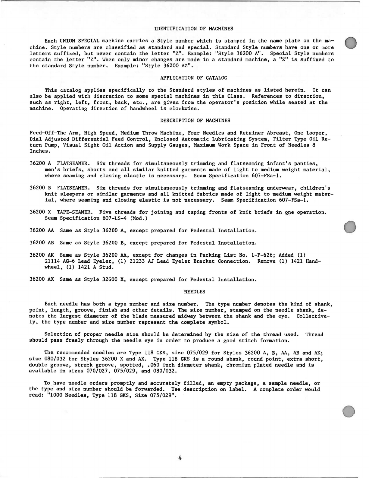
Feed-Off-The
Dial
turn
Inches.
36200 A
36200 B
36200 X
36200
36200
Operating
Adjusted
Pump,
men's
where seaming and
knit
ial,
Seam
Visual
FLATSEAMER. Six
briefs,
FLATSEAMER.
sleepers
where seaming and
TAPE-SEAMER. Five
Specification
AA
Same
AB
Same
applies
with
left,
direction
Arm,
High
Differential
Sight
shorts
or
as
Style
as
Style
specifically
discretion
front,
back,
of
Speed,
Oil
closing
Six
similar
36200
36200
Medium
Feed
Action
threads
and
all
elastic
threads
garments
closing
threads
607-LS-4 (Mod.)
A,
B,
to
to
some
etc.,
handwheel
Throw Machine,
Control,
and
Supply
for
simultaneously
similar
is
for
simultaneously
and
elastic
for
except
except
APPLICATION
the
Standard
special
are
given
is
clockwise.
DESCRIPTION
Enclosed
Gauges,
knitted
necessary.
all
knitted
is
not
joining
prepared
prepared
machines
from
Four
Automatic
Maximum
trimming
garments
Seam
trimming
necessary.
and
taping
for
Pedestal
for
Pedestal
OF
CATALOG
styles
in
this
the
operator's
OF
MACHINES
Needles
Lubricating
made
Specification
fabrics
fronts
of
machines
Class.
position
and
Retainer
Work
Space
and
flatseaming
of
light
and
flatseaming
made
of
Seam
Installation.
Installation.
light
Specification
of
knit
as
listed
References
while
Abreast,
System,
in
Front
infant's
to
medium
607-FSa-1.
underwear,
to
briefs
herein.
to
seated
Filter
of
Needles
weight
medium
607-FSa-1.
in
gne
It
direction,
at
One
Looper,
Type
Oil
8
panties,
material,
children's
weight
mater-
operation.
can
the
Re-
36200
AK
21114
wheel,
36200
AX
Each
point,
notes
ly,
should
size
double
available
the
read:
length,
the
the
type
Selection
pass
The recommended
080/032
groove,
To
have
type
"1000
Same
AG-6
(1)
Same
needle
largest
number and
freely
for
in
sizes
needle
and
size
Needles,
as
Style
Lead
1421 A
as
Style
has
groove,
diameter
of
proper
Styles
struck
number
36200
Eyelet,
Stud.
32600
both a type
finish
size
needle
through
needles
36200 X and
groove,
070/027, 075/029,
orders
should
Type 118
AA,
(1)
21233 AJ Lead
X,
except
number and
and
of
the
number
size
the
needle
are
Type 118
spotted,
promptly
be
GKS,
except
other
blade
forwarded.
Size
for
prepared
details.
measured
represent
should
eye
AX.
Type 118
.060
and
080/032.
and
accurately
075/029".
size
be
in
GKS,
inch
changes
order
in
Eyelet
for
Pedestal
NEEDLES
number. The
The
size
midway
the
complete
determined
to
size
075/029
GKS
diameter
filled,
Use
description
Packing
Bracket
number, stamped on
between
by
produce
is a round
shank,
List
Connection.
Installation.
type
the
symbol.
the
a good
for
Styles
an
empty
on
size
shank,
chromium
label,
No.
1-P-626;
Remove
number
shank
package, a sample
of
stitch
36200
round
denotes
and
the
formation.
plated
A
complete
the
needle
the
thread
A,
B,
point,
needle
Added
the
eye.
(1)
kind
used.
AA,
extra
needle,
order
(1)
1421 Hand-
of
shank,
shank,
Collective-
Thread
AB
and
AK;
short,
and
is
or
would
de-
4
ILLUSTRATIONS
This
catalog
views
seen
will
the
of
various
in
their
be
number
actual
found a listing
of
pieces
has
been
sections
position
required
ORDERING
arranged
ofthe
in
the
of
the
parts
REPAIR
to
simplify
mechanism
machine.
with
in
the
particular
On
their
PARTS
ordering
are
shown
the
parts
view
repair
sothatthe
page
opposite
numbers,
being
parts.
parts
the
description
shown.
Exploded
maybe
illustration
and
Numbers
dicate
never
second
indicated
sub-assembly.
the
position
be
used
column.
Component
by
27
28
29
30
31
29478
29103 T
22587 E
22894 w
22764
32
33
36244
34
It
will
be
listed.
recommended,
this
when
will
shown
The
In
those
catalog,
the
be
mentioned
in
parts
the
in
the
first
of
in
ordering
parts
indenting
of
Example:
cs
269
18
noted
reason
cases
no
illustration.
in
so
the
where a part
specific
for
the
in
the
column
that
part
in
parts.
sub-assemblies
their
the
is
that
complete
usage
various
descriptions
Feed
above
description
Lift
Feed
Nut~
Connecting
Nut,
example
replacement
will
machines
are
reference
the
illustration.
Always
which
Eccentric
Lift
Ecc.
Screw-------------------------------
numbers
Reference
use
the
can
be
under
the
Assembly----------------
Assembly
only,
part
number
furnished
description
Ball
and
merely
number
listed
for
repairs
of
the
Joint--------
should
in
are
main
Screw------------------------------- 1
Screw------------------------------- 1
left
thread--------------------------
Rod--------------------------
right
sub-assembly
is
common
be
thread
that
of
to
mentioned
are
and1 if
------------------------
the
eccentric
these
should
all
not
necessary,
of
in
the
parts
be
ordered.
the
machines
the
description.
same,
the
and
bearing
individually
covered
the
specific
difference
are
not
is
not
However,
usage
will
inthe
1
1
2
1
1
1
by
be
At
the
shown
when
On
an
appear.
STYLE
in
only
Where
some
identification
Part
IMPORTANT!
OF
back
this
the
the
of
the
numbers
of
the
book.
part
construction
smaller
MACHINE
This
number
letter
represent
ON
book
parts,
is
FOR
will
will
facilitate
is
known.
IDENTIFYING
permits 1 each
and
stamped
the
ALL
ORDERS~
WHICH
be
found a numerical
locating
PARTS
part
on
in
same
PART
those
to
where
distinguish
part1 regardless
PLEASE
IS
5
the
illustration
is
stamped
construction
the
INCLUDE
ORDERED.
index
with
part
of
of
and
its
does
from
catalog
PART
all
the
description
part
number.
not
permit,
similar
in
which
NAME
parts
ones.
they
AND
USE
GENUINE
REPAIR
PARTS
Success
UNION
iaries
scientific
durability
are
insured
ance.
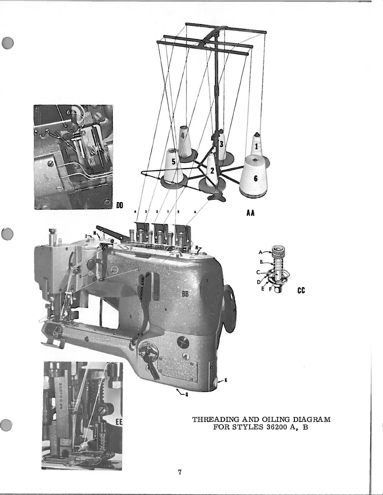
VIEWS
sing
ing
VIEW
upper;
and
SPECIAL
and
Prices
forwarded
AA
Thread
to
spring
CC:
Close-up
E,
Pass
"E".
in
authorized
principles,
are
are
unless
AND
BB:
as
3,
2,
at
Disc,
threads
the
operation
Repair
assured.
strictly
at
the
otherwise
indicated
1,
5 and 6
needle
of
tension
lower;
thru
Parts
buyer's
thread
as
distributors.
and
are
net
cash
risk
directed.
THREADING
in
illustration
in
order
frame
post
F,
Post
slots
"F"
of
these
furnished
They
made
assembly.
and
f.o.b.
AND
and
eyelet
Slot.
in
with
TERMS
A
tension
machines
by
the
are
utmost
subject
shipping
charge
OILING
on
opposite
passing
"G".
A,
Tension
post
can
be
secured
Union
designed
precision.
to
is
made
INFORMATION
needle
Special
according
change
point.
to
page,
threads
Nut;
"C",
and
without
cover
only
Corporation,
Maximum
Parcel
the
starting
UNDER
B,
Spring;
between
with
to
the
efficiency
notice.
Post
postage
with
the
C,
tension
genuine
its
most
shipments
Post;
All
and
#4,
stitch
discs
approved
shipments
progres-
D,
subsid-
and
are
insur-
unlock-
Disc,
"D"
VIEW
DD:
Close-up
VIEW
EE:
Close-up
Referring
and
"J".
ounces
125
seconds
"L",
located
the
front
these
of
cover.
time,
with
machine
and
at
the
gauges.
Automatic
oil
priming
recommended
Oil
back
"Q"
hole
in
can
When
is
is
of
be
in
of
of
Oil
capacity
the
top
at
100o
on
of
the
lubrication
be
observed
installing
may
running,
drained
drive
sure
the
the
looper
needle
to
illustration
reservoir.
Fahrenheit.
the
right
cylinder,
be
oil
pump
from
pulley.
hole
bottom
thread
thread
of
Class
side
respectively.
is
thru
windows
a new
necessary.
and
replace
is
inoperative.
machine
Belt
in
the
of
the
and
cover
sequence.
OILING
on
opposite
36200
Use a
featured
of
straight
The
the
''M"
machine
To
do
screws
at
two
cover
filter
cylinder.
thread
page,
is 2 ounces
level
main
or
must
box,
is
frame
Maintain
with a continuously
and
starting
so,
remove
BEFORE
places,
first
that
take-ups.
machine
in
mineral
checked
under
oil
"N"
in
crank
one
the
operating.
"O" and "R". "R"
be
removed.
the
screw
is
bottom
oil,
at
the
the
level
chamber
that
two
plug
goes
filled
oil
Saybolt
two
foot
between
driven
has
been
screws
If
oil
When
into,
at
the
reservoir
viscosity
sight
lifter
red
rotary
cover
idle
"P",
does
not
is
located
replacing
lines
caps
and
gauges
lever
lines
pump. Flow
and
for
of
and
front
some
fill
flow
below
the
up
with
"H"
2.5
90
"K"
of
to
and
at
top
holes
while
screw
Occasionally,
holder
of
the
shank
presser
No. 36273
foot
it
is
lifting
necessary
A,
guide
mechanism
to
collar
oil
No.
and
the
linkage
36273 K and
thread
6
tension
of
the
the
presser
various
release.
foot,
links
the
and
knife
bearings
AA
cc
THREADING
FOR
7
AND
STYLES
OILING
36200
DIAGRAM
A,
B

INSTALLATION
OF
MACHINE
Where a power
on a Union
the
use
board
It
is
of
more
table
(1#35895 R)
Corrugated
Add
three
left
and
rear
front
Stud
Correct
(1#22652
before
Pulley.
F-20)
tightening
Tighten
sufficiently
finger
milled
milled
Screws
pressure.
flat
groove.
(1#25
Refer
Lever
(1#421
The
(I#
36280
D-38)
speed
operation.
of 2 1/4
inches,
Special
Rubber
may
be
convenient
into
the
Isolator
Felt
Sleeves
Studs,
so
that
Screws
and
Belt
tight
if
as a more
Do
S).
to
Page
F).
or
Lifter
of
Since
the
the
stand
table
board
Feet
(1#21371
prepared
base
(1#660-275)
(1#660-161)
tighten
Drive
Unit
for
assembling
are
packed
securely.
by
while
Secure
favorable
not
tighten
25;
assemble
The
Rod.
the
Machine
Handwheel
size
or
line-shaft
to
to
set
of
the
first
has
in
Place
turning
one
side
the
flange
hole
of
the
close
in
order
especially
the
this
on
Nut
to
isolation
Machine
Unit
order
each
with
1/32
JT),
obtain
up
Drive
in
about
MOUNTING
Machine
installation
small
parts
short
flange
of
remains
position
position,
againstthread
Lifter
is
Motor
sf;
4200
Pulley,
Lever
to
R.
which
Pulley
obtain
on
as
and
to
Stud
and
fingers
less
to
Drive
box.
Belt
(1#21261
Adjustable
straight
by
tightening
move
on
Pulley
(1#36280
the
Fulcrum
MAClllNE
P.
M. , which
is
may
is
desired,
the
benefits
wooden
shown
Drive
tighten.
each
Stud
press
only.
gap
at
THE
Unit
Freedom
Pulley
the
the
Set
F)
grooved
be
approximated
floors.
on
Planograph
Unit
first
Add
and
into
Lock
rear.
MAClllNE
are
of
M-210)
opposite
the
Screw
Core.
and
the
Screw
SPEED
may
be
for a 1#1
it
is
of
isolated
However,
and add
one
steel
set
Unit
holes.
into
position
Lock
into
Allen
screw
first
over
clockwise
side
Set
Screw.
to
this
Add
Belt
Link
will
provide
modified,
or
by
recommended
moWlt_
ing,
1f
with
template
Machine
Washer
on
table,
Assemble
with
balance
second
position
Head
Cap
in
Screws
hole
body
Adjustable
to
increase
may
be
deflected
If
the
hole.
Guard
(1#36280
Make
(1#36295
G).
more
dependent
3L
section
the
following
that
the
which
is
such a board
PL443.
later.
Insert
(1#21371 UE)
Studs
extending
of
parts
Nut.
with
second
3/8
permits
- 16 x 1
Machine
Pulley
the
pitch
inwardly
open
screw
sure
Screw
J)
with
Two
holes
lift.
Attach
upon
Vee
the
Belt,
formula:
machine
fu~her
lS
be
imp~oved
not
available,
the
and
one
through
per
Tighten
first
Nut.
1/4
to
and
then
diameter.
1/4
hole
inch
lines
seats
two
Fillister
are
provided
the
Lifter
conditions
has a pitch
installed
three
Neoprene
PL443.
Nut
inch
be
levelled
on
Machine
Belt
by
up
on
of
diameter
by
Studs
holes.
On
on
long
light
with
flat
Head
in
the
Chain
the
a
is
a
of
For
Union
diameter.
variable
pitch
tachometer
It
is
unnecessary
Fasten
convenient
machine)
for
Brackets
to
prevent
PREFERRED
The
travel
may
for
adequate
more
on
Machine
indica~es
be
usedm
the
Looper
strength.
It
is
more
unif.orm
operation
Special
Due
to
variations
pulley,
to
determine
to
Thread
to
bring
Stand
into
threading.
for
attaching
interference
THREADS
will
right
the
Looper
since
economical
stitch,
and
material.
Electro
an
absolute
the
remove
to
direct
Thread
between
operate
twist.
as
there
over a period
thereby
Pitch
Dia.
Drive
in
actual
actual
the
Belt
table
board
line
Lead-in
Thread
satisfactorily
A
70-3
well
is
asthe
insufficient
reducing
of
Motor
Pulleys,
pitch
value
speed.
Guard
SETTING
with
the
threads
Cones
THREADING
or
80-3
coverthread.
oftime
the
Pulley
add
diameters,
will
not
The
tachometer
(1#36295
three
which
Guides
should
and
with
cord
yarn
to
to
possibility
1/4
be
J),
UP
THREAD
(i#SC303)
lead
the
THE
either
is
used
resist
use
the
of
2. 25 x
=
inch
to
R.
the
motor
obtained
and
should
since a hole
STAND
Flat
into
the
be
located
Lead-in
Guides.
MACiflNE
left
or
right
in
the
The
25/1
abrasion
better
down-time.
R.
P.
M.
of
Machine
P.
M.
of
Motor
calculated
speeds,
pitch
tension
therefore,
be
has
Head
Eyelets
as
shown
twist,
needles
to
28/1
of
wearing,
grades
applied
Wood
been
provided
Screws
of
Machine.
on
PL437
although
and
30/2
yarns
ofthread
to
are
although
However, a selection
diameter
of
it
becomes
the
to
definitely
and
the
end
for
(1#12Xl)
See
(also
the
direction
50/2
the
yarn
to
obtain
Jack
necessary
of
the
this
at a location
PL425
packed
soft
mercerized
NOT
seam
since
of
thread
the
Belt
and
to
MACm:~
purpose.
(packed
with
machine)
of
the
recommended
has
more
they
produce
will
outside
size
use
Shaft.
most
with
Looper
yarn
than
depend
of
a
a
SEQUENCE
_Mac?J.ne
pos1tiorung.
Foot.
Place
Eyelets
Cones
as
OF
THREADING
has
been
Sample
on
shown
on
sewed
of
fabnc
Thread
PL425.
_off
should
Stand
Unwrap
at
factory
Seats
and
be
closely
and
threads
pull
PL425
observed
thread
from
is
packed
from
Presser
as
to
cones
Bar,
,.-£~
h
each
introduction
on
stand
cut
9
machine
of
thru
off
and
as
guide
fabric
Lead-in
tie
to
to
threading
between
Guides
threads
toes
to
Tension
from
and
of
the
cone
Presser
Post
Cones.
Turn
Pull
thread
With
and
the
Handwheel
threads
above
stitch
knots
Needle
formation.
from
Bar
clockwise.
above
and
cut
raised,
needle
off
lift
Stop
with
eyes
close
Presser
Needle
thru
to
Needle
Foot
Bar
system
and
at
Eyes.
remove
top
until
the
of
its
knots
DO
factory
stroke.
pass
NOT
thru
RE-THREAD
sample.
Needle
Observe
Bar
Head
NEEDLES
method
Eyelet.
AT
of
entering
THIS
Cut
off
TIME.
Foot
Looper
to
re-thread
THREAD
observe
tension;
section
UNLOCKING
then,
downward
mark
threads
the
free
formed.
REPLACING
formation
Check
when
on
Turn
turn
on
the
to
With
threads
needles.
If
the
ends
Tension
"Adjustment
the
the
approximately
be
stitch
of
This
and
Cover
Looper
of
Release
is rai
STITCH
Cover.
from
unlocked,
is
unlocked
the
threads
termed
NEEDLE
Thread
stitch.
the
NEEDLES
Foot
THE
Handwheel
Handwheel
Head
pulled
Without a chain,
all
is
THE
and
Cover
and
when
sed,
of
Tension
in
the
in
the
1/8
Lift
under
it
firmly
"starting
can
place
all
operating
reverse
inch
the
the
must
material
and
now
be
Thread
one
Foot
is
threads
Release".
to
where
Presser
Foot
be
it
is
desired
behind
the
chain".
tied
and
Carrier.
ply
of
material
raised
must
or
clockwise
direction
the
top
Foot
freely.
understood
must
be
to
the
Foot
Machine
pulled
before
be
completely
until
of
the
as
high
that
under
start
before
thru,
under
sewing
direction
the
Needle
Needle
as
it
is
the
Foot
the
machine
starting
will
with
Needle
Foot.
with
free.
Bar
Lever
possible,
only
when
then
chain
Manually
power.
If
until
has
Thread
thus
to
introduce
starting
without
the
machine,
indefinitely.
Bar
these
the
Needle
reached
opening
material,
at
highest
turn
When
conditions
Eyelet
work
to
sew.
until a small
point.
clockwise
Foot
is
Bar
is
its
highest
is
in line
the
Tensions
under
it
is imperative
down,
are
in
its
position
the
It
is
several
all
not
met,
lowest
with
the
which
Foot
amount
unnecessary
times
and
threads
from
refer
position,
and
moved
top
allow
behind
to
hold
of
chain
have
of
the
to
the
the
is
Union
matically
to
Looper.
To
remove
seated
adjustments
Familiarity
but
NEEDLE
Presser
Knife
Cover,
partially
of
remove
on
If
the
care
If
the
To
remove
(#36270)
Needle
Needle,
should
Foot,
left
withdraw
Special
assists
The
Needle,
flat
(Page
machine
be
made
with
be
TO
LOOPER
machine
Throat
Presser
and
(#36289 A,
to
Looper
Needles
operator
Retainer,
To
replace
27).
has
been
in
the
machine
taken
SETTING
is
assembled
Plate
release
Page
Presser
setting,
for
the
FLA
in
to
bring
correctly
the
Needle
Needle,
right
TSEAMER
locating
of
Bar
make
INSTRUCTIONS
disassembled,
the
to
Foot
observe
following
will
and
(#36220),
knife
27)
Bar
sequence,
permit
that
and
it
is
Main
Feed
raise
pressure
and
Presser
(#36278),
individual
the
desired
the
the
fourth
to
maximum
certain
FOR
re-adjusting
which,
proper
Dog
Needle
by
Removal
adjustments
relationship
to
should
unclamping
Foot
Brace
are
made
relative
Needle,
height,
that
Shank
SEWING
for
through
proceed
be
removed,
Bar
to
maximum
Knife
(#36278
of
Throat
with
two
is
flats
of
Needles
no
thread
inserted
orienting
position
requires
break
ADJUSTMENTS
sewing-off
experience,
of
of
with
Plate
is
an
assembled
adjustment
the
Needle
height
Guide
E),
(#36273
Release
and
required,
Main
on
at
to
has
is
to
and
Presser
front
eye,
full
Looper
remove
Feed
of
Shank.
in
Needle
and
consequently
loosen
depth
and
and
setting,
Retainer
Remove
Bar
Dog
it
generally
to
will
proven
machine
maintained,
B),
Bar
Screw
that
is
suggested
correct
Guide
permit
This
design
Head
with
has
(#22738
Screw
satisfactory,
malfunction,
the
Upper
(#36211),
Detachable
(#36278
observation
auto-
respect
no
flat.
H)
and
is firmly
that
the
Knife,
Upper
Head
B)
and
10
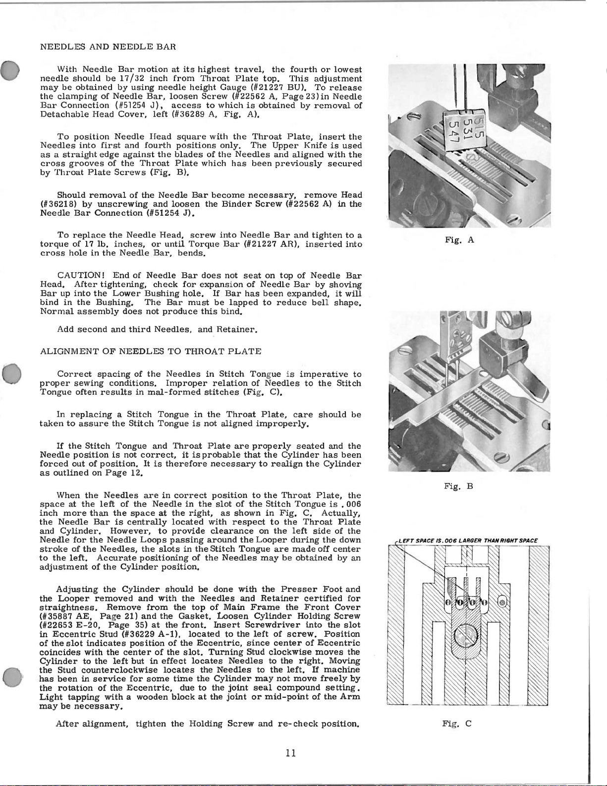
NEEDLES
With
needle
may
the
Bar
Detachable
Needles
as a straight
cross
by
Needle
should
be
obtained
clamping
Connection
To
position
into
grooves
Throat
AND
of
Head
first
edge
Plate
NEEDLE
Bar
be
17/32
by
Needle
( #51254
Cover,
Needle
and
against
of
the
Screws
motion
using
Bar,
fourth
Throat
BAH
inch
needle
J),
left
Head
the
(Fig.
at
its
from
height
loosen
access
(#36289
square
positions
blades
Plate
B).
highest
Throat
Gauge
Screw
to
which
A,
with
only.
of
the
which
travel,
Plate
(#22562
Fig.
the
Needles
has
is
A).
the
fourth
top.
(#21227 BU).
obtained
Throat
The
been
This
A,
Page23)in
Plate,
Upper
and
aligned
previously
or
adjustment
To
by
removal
insert
Knife
lowest
release
Needle
the
is
used
with
the
secured
of
Should
(#36218)
Needle
To
torque
cross
CAUTION!
Head.
Bar
bind
Normal
A
ALIGNMENT
Correct
proper
Tongue
In
taken
If
Needle
forced
as
outlined
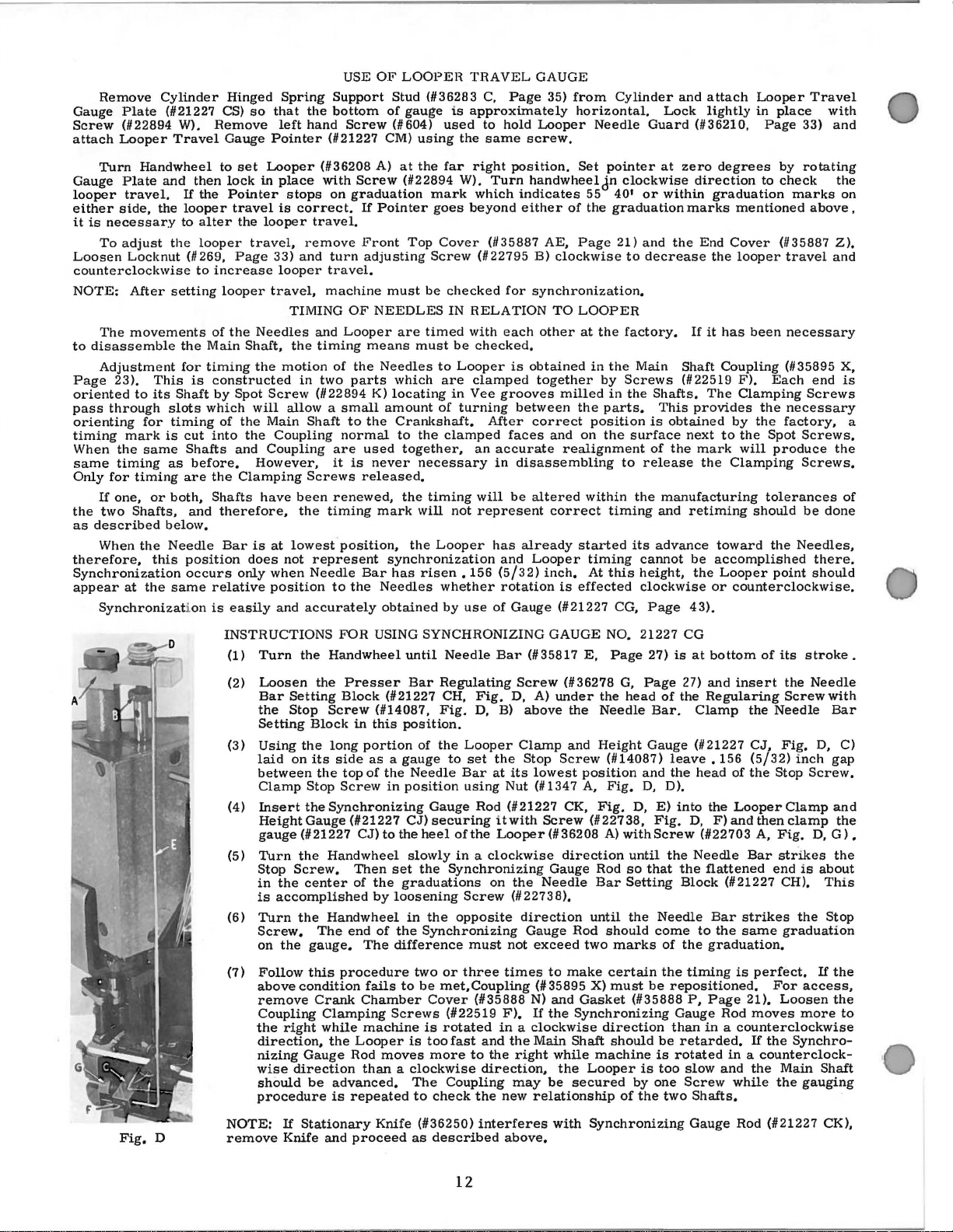
When
space
inch
the
Needle
and
Needle
stroke
to
the
adjustment
removal
by
Bar
replace
of
17
hole
After
up
into
in
the
assembly
dd
second
sewing
often
replacing a Stitch
to
assure
the
Stitch
position
out
of
the
at
the
more
Cylinder.
for
the
of
the
left.
unscrewing
Connection
the
Needle
lb.
inches,
in
the
Needle
End
tightening,
the
Lower
Bushing.
does
and
OF
NEEDLES
spacing
conditions.
results
the
Tongue
is
not
position.
on
Page
Needles
left
than
of
the
Bar
is
centrally
However,
Needle
Needles, the
Accurate
of
the
Cylinder
of
the
and
(#51254
or
Bar,
of
Needle
check
Bushing
The
not
third
Needles,
of
the
in
mal-formed
Stitch
and
correct,
It
is
12.
are
the
Needle
space
Loops
positioning
Needle
loosen
J).
Head,
until
bends.
Bar
for
hole.
Bar
produce
TO
Needles
Improper
Tongue
Tongue
Throat
it
therefore
in
correct
at
the
located
to
provide
passing
slots
position.
Bar
become
the
screw
Torque
does
expansion
If
must
be
this
and
THROAT
in
relation
stitches
in
the
is
not
Plate
is
probable
necessary
position
in
the
right,
with
clearance
around
in
the
Stitch
of
the
Binder
into
Needle
Bar
not
Bar
lapped
bind.
Retainer
PLATE
Stitch
Throat
aligned
are
slot
of
as
shown
respect
the
Tongue
Needles
necessary,
Screw
(#21227 AR),
seat
of
has
.
Tongue
of
(Fi
g. C).
improperly.
properly
that
to
the
Looper
(#22562
Bar
on
top
Needle
been
expanded,
to
reduce bell
is
Needles
Plate,
the
Cylinder
to
realign
the
Throat
Stitch
in
Fig.
to
the
on
the
are
may
be
left
during
made
remove
A)
and
tighten
inserted
of
Needle
Bar
by
imperative
to
the
care
should
seated
the
Plate,
Tongue
C.
Actually,
Throat
side
the
off
obtained
Head
in
the
to
into
Bar
shoving
it
will
shape.
to
Stitch
be
and
the
has
been
Cylinder
the
is
• 006
Plate
of
the
down
center
by
an
a
Fig.
Fig.
A
B
Adjusting
the
Looper
straightness.
(#35887 AE, Page 21)
(#22653
in
Eccentric
of
the
slot
coincides
Cylinder
the
Stud
has
been
the
rotation
Light
tapping
may
be
After
the
Cylinder
removed
Remove
E-20,
nece·ssary.
Page
Stud
indicates
with
to
counterclockwise
in
alignment,
(#36229
position
the
center
the
left
but
service
of
for
the
Eccentric,
with a wooden
and
with
from
and
35)
at
A-1),
of
in
some
tighten
should
the
the
Gasket.
the
of
the
effect
locates
time
block
the
the
top
front.
located
the
slot.
locates
due
Holding
be
done
Needles
of
Main
l..oosen
Insert
to
Eccentric,
Turning
Needles
the
Needles
the
Cylinder
to
the
the
joint
joint
Screw
at
with
the
and
Retainer
Frame
Cylinder
Screwdriver
the
left
since
Stud
clockwise
to
to
the
may
seal
or
mid-point
and
Presser
certified
the
Front
Holding
of
center
into
screw.
of
the
right.
left.
not
move
compound
re-check
Foot
Cover
Screw
the
Position
Eccentric
moves
Moving
If
machine
freely
setting.
of
the
position.
and
for
slot
the
by
Arm
11
Fi
g. c
Remove
Gauge
Screw
attach
Turn
Gauge
looper
either
it
is
necessary
To
Loosen
Plate
(1122894
Looper
Handwheel
Plate
travel.
side,
the
adjust
Locknut
Cylinder
(#21227 CS)
and
counterclockwise
NOTE:
to
After
The
movements
disassemble
Adjustment
Page
23),
oriented
pass
orienting
timing
When
same
Only
If
the
two
as
described
When
therefore,
to
through
for
mark
the
same
timing
for
timing
one,
Shafts,
the
This
its
slots
is
as
or
below.
Needle
this
Synchronization
appear
at
the
Synchronization
W),
Travel
then
If
the
looper
to
alter
the
looper
(# 269,
to
setting
the
for
is
Shaft
timing
cut
Shafts
before,
are
both,
and
position
occurs
same
Hinged
so
Remove
Gauge
to
set
lock
in
Pointer
travel
the
travel,
Page
increase
looper
of
the
Main
timing
Needles
Shaft,
the
constructed
by
Spot
which
of
into
will
the
the
and
However,
the
Clamping
Shafts
have
therefore,
Bar
is
does
only
relative
is
easily
Spring
that
the
left
hand
Pointer
Looper
place
stops
is
correct.
looper
travel.
remove
33)
and
looper
travel,
TIMING
and
the
motion
in
Screw
(/122
allow a small
Main
Shaft
Coupling
Coupling
Screws
been
the
at
lowest
not
represent
when
Needle
position
and
accurately
USE
OF
Support
bottom
Screw
(/121227 CM)
(#36208 A)
with
Screw
on
graduation
If
Pointer
Front
turn
adjusting
travel.
machine
OF
NEEDLES
Looper
timing
of
two
means
the
parts
Needles
894 K)
to
the
normal
are
used
it
is
never
released,
renewed,
timing
mark
position,
Bar
to
the
Needles
LOOPER
Stud
(#36283
of
gauge
using
the
is
used
the
far
(#604)
at
(/122894 W).
mark
goes
Top
Cover
Screw
must
be
checked
IN
are
timed
must
be
to
are
in
of
Looper
turning
which
locating
amount
Crankshaft,
to
the
clamped
together,
necessary
the
timing
will
not
the
Looper
synchronization
has
risen.
whether
obtained
by
use
TRAVEL
C,
Page
GAUGE
35)
approximately
to
hold
same
right
Turn
which
beyond
(#35887
(1122795
Looper
screw.
position.
handwheelJn
indicates
either
AE,
B)
for
synchronization,
RELATION
with
each
other
checked,
is
clamped
Vee
obtained
together
grooves
between
After
correct
faces
an
accurate
in
disassembling
will
be
altered
represent
has
already
and
(5/32)
Looper
inch,
156
rotation
of
Gauge
from
horizontal.
Needle
Set
pointer
55
of
the
graduation
Page
clockwise
TO
LOOPER
at
the
in
the
by
milled
the
in
parts,
position
and
on
the
realignment
within
correct
timing
started
timing
At
is
this
effected
(#21227 CG,
Cylinder
Guard
clockwise
401 or
21)
and
to
decrease
factory,
Main
Screws
the
Shafts.
This
is
surface
of
to
release
the
and
its
advance
cannot
height,
clockwise
Page
and
attach
Lock
lightly
(1136210,
at
zero
degrees
direction
within
marks
the
End
If
Shaft
(1122519
graduation
mentioned
Cover
the
looper
it
has
Coupling
F),
The
Clamping
provides
obtained
the
next
mark
the
by
to
the
will
Clamping
manufacturing
retiming
toward
be
accomplished
the
Looper
or
counterclockwise.
43),
Looper
in
place
Page
by
to
check
(1135887
travel
been
necessary
(1135895 X,
Each
the
necessary
the
factory,
Spot
produce
tolerances
should
the
point
Travel
with
33)
and
rotating
marks
above,
and
end
Screws
Screws.
Screws.
be
done
Needles,
there.
should
the
on
Z).
is
a
the
of
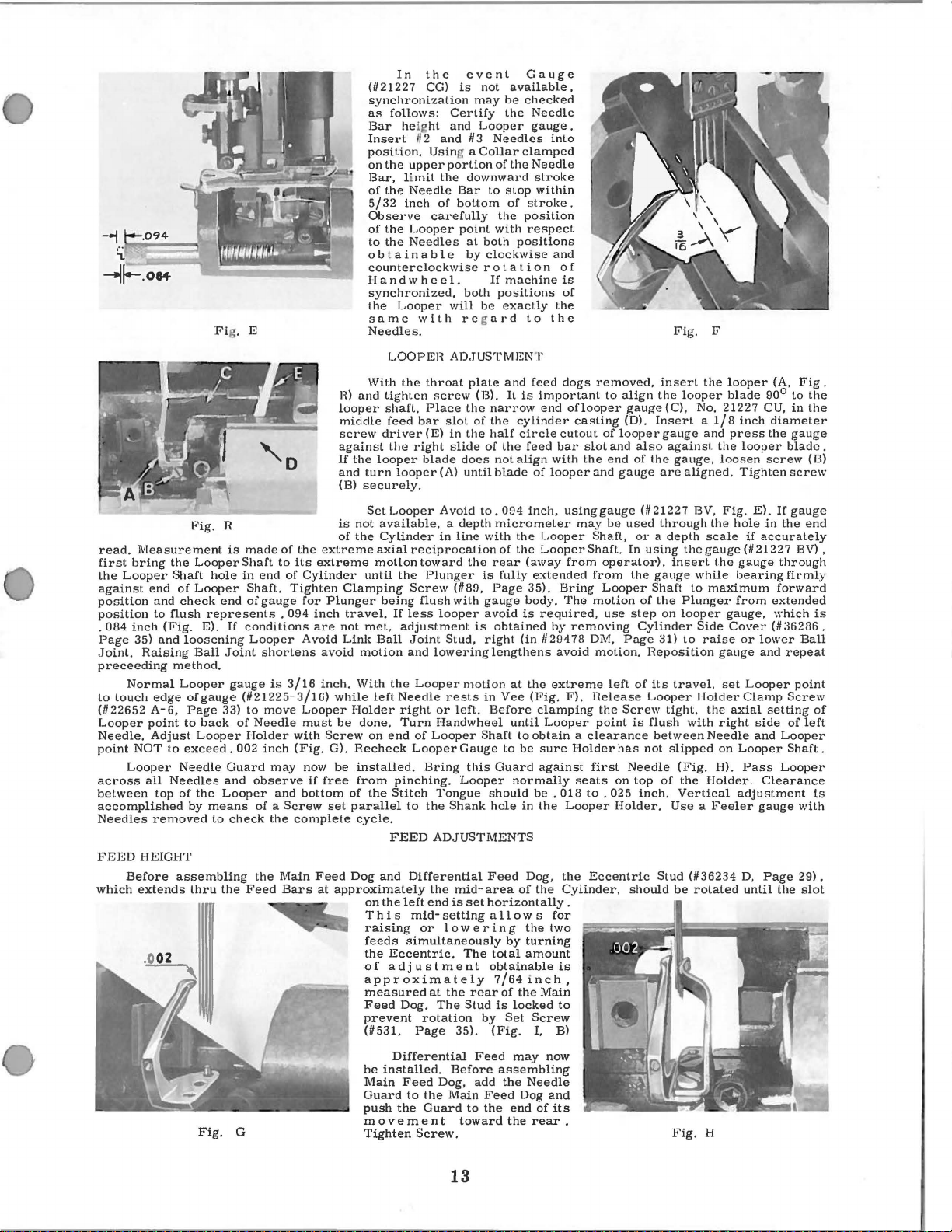
INSTRUCTIONS
(1)
Turn
the
(2)
(3)
(4)
(5)
(6)
(7)
Loosen
Bar
the
Setting
Using
laid
between
Clamp
Insert
Height
gauge
Turn
Stop
in
is
Turn
Screw,
on
Follow
above
remove
Coupling
the
the
Setting
Stop
Block
the
on
its
the
Stop
the
Gauge
(#21227
the
Screw.
the
center
accomplished
the
The
the
gauge,
this
condition
Crank
Clamping
right
while
direction,
nizing
Gauge
wise
direction
should
be
procedure
FOR
USING
Handwheel
until
Presser
Block
(#
Screw
long
side
top
Screw
21227 CH,
(1114087,
in
this
portion
as a gauge
of
the
in
position.
position
Synchronizing
(#21227
CJ)
Handwheel
Then
of
Handwheel
end
to
the
by
of
The
CJ)
the
slowly
set
graduations
loosening
in
the
difference
procedure
fails
to
Chamber
Screws
machine
the
Looper
Rod
moves
than a clockwise
advanced,
is
repeated
SYNCHRONIZING
Bar
Needle
Regulating
Bar
Fig.
Fig.
D, B)
of
the
Looper
to
set
Needle
Gauge
securing
heel
the
Bar
at
using
Nut
Rod (#21227 CK,
it
of
the
Looper
in a clockwise
the
Synchronizing
on
Screw
the
opposite
Synchronizing
must
two
or
three
be
met,Coupling
Cover
(#22519
is
rotated
is
too
fast
more
times
(#35888
F),
in a clockwise
and
to
the
direction,
The
Coupling
to
check
the
new
GAUGE
(#35817
Screw
D, A)
under
above
Clamp
Stop
its
lowest
(/11347 A,
with
Screw
(#36208
Gauge
the
Needle
(/122738),
direction
Gauge
not
exceed
to
(#35895 X)
N)
and
If
the
the
Main
right
while
may
be
relationship
NO, 21227
E,
Page
(#36278 G,
the
the
Needle
and
Height
Screw
(1114087)
position
Fig,
Fig.
(#22738,
A)
direction
Rod
Bar
until
Rod
should
two
marks
make
certain
must
Gasket
Synchronizing
direction
Shaft
should
machine
the
Looper
secured
27)
Page
head
Bar.
Gauge
and
D, D).
D,
with
Screw
until
so
that
Setting
the
be
(#35888
is
by
of
the
CG
is
at
bottom
27)
of
and
the
Regularing
Clamp
(1121227
leave,
the
head
E)
into
Fig.
the
D,
(#22703 A,
the
Needle
the
flattened
Block
Needle
come
to
of
the
graduation,
the
timing
repositioned,
P,
Page
Gauge
than
be
is
too
one
in a counterclockwise
retarded,
rotated
slow
Screw
two
Shafts,
of
its
insert
the
Screw
the
Needle
CJ,
(5/32)
the
Stop
then
Fig.
inch
Clamp
clamp
156
F)
of
Looper
and
Fig.
Bar
strikes
end
(#21227 CH),
Bar
strikes
the
same
graduation
is
perfect,
For
21).
Rod
Loosen
moves
If
the
Synchro-
in a counterclock-
and
the
while
Main
the
stroke.
Needle
with
Bar
D, C)
gap
Screw.
and
D,
G),
the
is
about
This
the
Stop
If
the
access,
the
more
Shaft
gauging
the
to
Fig,
D
NOTE:
remove
If
Stationary
Knife
and
Knife
proceed
(#36250)
as
described
interferes
above.
with
12
Synchronizing
Gauge
Rod
(#21227 CK),
read.
Measurement
first
bring
the
Looper
against
position
position
.
Page
Joint.
preceeding
to
(#
Looper
Needle.
point
across
between
accomplished
Needles
FEED
which
end
and
084
to
inch
35)
Raising
Normal
touch
edge
22652 A-6,
point
Adjust
NOT
Looper
all
top
removed
HEIGHT
Before
extends
(Fig.
and
Fi
Fig.
the
Looper
Shaft
hole
of
Looper
check
flush
method.
to
Needles
end
represents . 094
E).
loosening
Ball
Looper
ofgauge
Page
to
back
Looper
exceed.
Needle
of
the
by
means
to
assembling
thru
Fig.
g. E
R
is
made
Shaft
in
end
Shaft.
of
gauge
If
conditions
Looper
Joint
shortens
gauge
is
(/121225-3/16)
33)
to
move
of
Needle
Holder
002
inch
Guard
may
and
observe
Looper
the
of a Screw
check
the
Feed
G
and
the
of
the
to
its
of
Cylinder
Tighten
for
Avoid
3/16
Looper
must
with
(Fig.
bottom
complete
Main
Bars
H)
looper
middle
screw
against
If
and
(B)
is
of
extreme
extreme
Plunger
inch
are
not
Link
avoid
inch.
while
be
Screw
G).
now
be
if
free
set
Feed
at
approximately
In
(//21227 CG)
synchronization
as
follows:
Bar heig
Insert
position.
on
the
Bar,
limit
of
the
5/32
inch
Observe
of
the
to
the
obtain
counterclockwise
II
and w he e 1.
synchronized,
the
Looper
same
Needles.
LOOPER
With
the
and
tighten
shaft.
feed
driver
the
the
looper
turn
looper
securely.
SetLooper
not
available, a depth
the
Cylinder
axial
motion
until
Clamping
travel.
Holder
of
parallel
Dog
the
being
If
less
met,
adjustment
Ball
motion
With
done.
Recheck
installed.
from
cycle.
and
the
left
Needle
right
Turn
on
end
pinching.
the
Stitch
to
FEED
and
on
the
left
T
hi s mid-
raising
feeds
simultaneously
the
Eccentric.
of
ad
j u s t
approximately
measured
Feed
Dog.
prevent
(#531,
Differential
be
installed.
Main
Feed
Guard
to
push
the
movement
Tighten
the
event
is
Certify
ht
and
fl
2
and
/13
Usin
g a
upper
portion
the
Needle
Looper
Needles
with
bar
right
reciprocal
Screw
flush
Joint
Looper
of
Looper
Differential
Page
Screw.
downward
Bar
of
bottom
carefully
point
at
a b 1 e
by
both
will
regard
AD.TUSTMENT
throat
plate
screw
Place
the
slot
(E)
blade
toward
Plunger
Bring
the
or 1 ow e ring
rotation
the
Guard
of
in
the
slide
does
(A)
until
Avoid
in
line
the
(1189,
with
looper
Stud,
lowering
motion
rests
or
left.
Handwheel
Looper
Gauge
this
Looper
Tongue
Shank
ADJUSTMENTS
the
mid-
end
is
set
setting
The
men t obtainable
at
the
rear
The
Stud
35).
Before
Dog,
Main
to
toward
not
available,
may
be
checked
the
Looper
Needles
Collar
clamped
of
the
to
stop
of
the
position
with
both
positions
clockwise
rot
at
If
machine
positions
be
exactly
and
(B).
It
is
narrow
the
cylinder
half
circle
of
the
not
align
blade
to.094
micrometer
with
the
ion
of
the
rear
is
fully
Page
gauge
avoid
is
Feed
add
is
obtained
right
(in
lengthens
at
in
Vee
Before
until
Shaft
to
to
be
Guard
normally
should
hole
in
Feed
area
of
horizontally.
a 11
ow s for
by
total
7/64
of
the
is
locked
by
Set
(Fig.
may
assembling
the
Feed
Dog
the
end
the
Gauge
Needle
gauge.
into
Needle
stroke
within
stroke.
respect
and
ion
of
is
of
the
to
the
feed
dogs
oflooper
casting
cutout
bar
slot
with
the
and
usinggauge
may
Shaft,
Shaft.
from
from
Bring
The
motion
by
removing
avoid
extreme
F).
Release
Holder
first
seats
to . 025
Looper
the
Eccentric
Cylinder,
is
to
its
removed,
to
of
and
end
be
operator).
Looper
use
motion.
left
the
point
has
on
Holder.
important
end
feed
of
looper
inch,
Looper
Looper
(away
extended
35).
body.
required,
1129478 Di\1,
the
(Fig.
clamping
Looper
obtain a clearance
sure
against
be . 018
the
Dog,
the
the
two
turning
amount
inch,
Main
Screw
I, B)
now
Needle
and
of
rear.
Fig.
insert
align
the
gauge
(C), No.
(D).
Insert a 1/8
looper
gauge
also
against
of
the
gauge
Page
Screw
gauge,
are
(1121227 BV,
used
through
or a depth
In
using
insert
the
gauge
Shaft
of
the
step
on
Cylinder
31)
Reposition
of
its
travel,
Looper
tight,
is
flush
between
not
slipped
Needle
top
of
inch. Vertical
Use a Feeler
Stud
should
be
Fig.
F
the
looper
and
the
loosen
aligned.
the
scale
the
gauge
the
while
to
maximum
Plunger
looper
Side
to
raise
gauge
Holder
the
with
right
Needle
on
(Fig.
I-Il.
the
Holder.
(1136234 D,
rotated
H
looper
blade
21227
inch
press
looper
Tighten
Fig.
E).
hole
if
(#21227
gauge
bearing
from
gauge,
Cover
or
lower
set
Looper
Clamp
axial
side
and
Looper
Pass
adjustment
gauge
until
(A,
Fig.
90°
to
CU.
in
diameter
the
gauge
blade.
screw
screw
If
gauge
in
the
end
accurately
BV) ,
through
firmly
forward
extended
which
(/I :l6286 .
Ball
and
repeat
point
Screw
setting
of
left
Looper
Shaft.
Looper
Clearance
with
Page
29),
the
slot
the
the
(B)
is
of
is
13
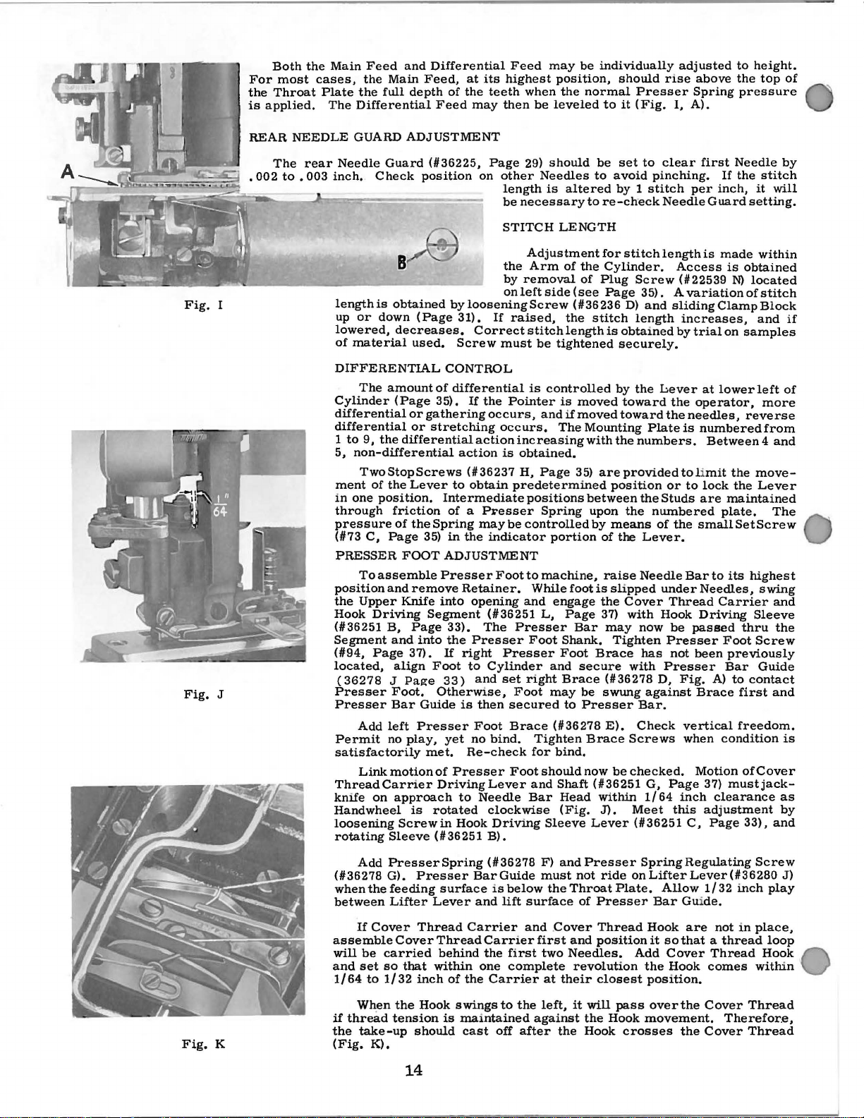
Both
For
the
Throat
is
applied.
REAR
The
•
002
the
most
NEEDLE
rear
to • 003
Main
cases,
Plate
The
Needle
inch.
Feed
and
the
Main
the
full
Differential
GUARD
depth
ADJUSTMENT
Guard
Check
Differential
Feed,
position
at
of
the
Feed
(#36225,
its
may
on
highest
teeth
then
Page
other
length
be
Feed
when
be
29)
Needles
is
necessary
may
be
position,
the
leveled
should
altered
individually
should
normal
to
it
be
set
to
avoid
by 1 stitch
to
re-ch·eck
rise
Presser
(Fig.
to
clear
pinching.
Needle
adjusted
above
Spring
I,
A).
first
per
Guard
to
the
Needle
If
the
inch,
height.
top
pressure
stitch
it
will
setting.
of
by
Fig.
Fig.
STITCH
B
length
is
I
J
up
lowered,
of
DIFFERENTIAL
Cylinder
differential
differential
1
to
5,
ment
in
through
pressure
(#73
PRESSER
position
the
Hook
(#36251
Segment
(
#94,
located,
(36278 J Page
Presser
Presser
Permit
satisfactorily
Thread
knife
Hand
loosening
rotating
obtained
or
down
material
one
decreases.
The
amount
(Page
9,
the
Two
Stop
of
position.
C,
To
assemble
and
Upper
Driving
B,
Page
Carrier
on
wheel
differential
the
friction
of
Page
FOOT
Knife
and
align
Foot.
Bar
left
no
play,
approach
Screwin
Sleeve
non-differential
Add
Linkmotionof
by
(Page
used.
CONTROL
of
differential
35).
or
gathering
or
stretching
Screws
Lever
37).
is
to
Intermediate
of
the
Spring
35)
in
ADJUSTMENT
Presser
remove
into
Segment
Page
33).
into
the
If
Foot
33)
Otherwise,
Guide
Presser
yet
met.
Presser
Driving
rotated
( # 36 251
31).
Screw
action
is
to
Hook
the
by
on
loosening
If
raised,
Correctstitchlengthis
must
If
the
Pointer
occurs,
occurs.
action
increasing
is
(#36237
obtain
a P:t;"esser
the
Retainer.
right
to
Re-check
maybe
indicator
Foot
opening
(#36251
The
Presser
Presser
Cylinder
and
set
then
secured
Foot
Brace
no
bind.
Footshouldnow
Lever
Needle
clockwise
Driving
B).
predetermined
Presser
Foot
LENGTH
Adjustment
Arm
of
removal
left
side
Screw
the
be
tightened
is
controlled
is
and
if
The
obtained.
H,
Page
positions
Spring
controlled
portion
to
machine,
While
engage
L,
Foot
and
may
(#36278
Tighten
for
bind.
and
Shaft
Bar
Sleeve
foot
Page
Shank.
Foot
Brace
to
Head
(Fig.
and
right
for
the
Cylinder.
of
Plug
(see
Page
( # 36 236
stitch
moved
moved
Mounting
with
35)
are
position
between
upon
by
means
of
raise
is
slipped
the
37)
Bar
may
Tighten
Brace
secure
(#36278
be
swung
Presser
E).
Brace
be
(#36251
within
J).
Lever
stitch
length
Screw
35). A variation
D)
and
sliding
length
obtained
securely.
by
the
Lever
toward
toward
the
provided
the
the
Cover
with
the
Plate
numbers.
or
the
Studs
numbered
of
Lever.
Needle
under
Thread
Hook
now
Presser
has
with
Presser
D,
against
Bar.
Check
Screws
checked.
G,
Page
1/64
Meet
(#36251
the
the
be
not
this
is
Access
by
made
(#22539
Clamp
increases,
trial
on
at
lower
operator,
needles,
is
numbered
Between 4 and
to limit
to
lock
are
plate.
small
Bar
to
Needles,
Carrier
Driving
passed
Foot
been
Fig.
A)
Brace
vertical
when
condition
Motion
37)
inch
clearance
adjustment
C,
Page
within
is
obtained
N)
located
of
stitch
Block
and
samples
left
more
reverse
from
the
move-
the
Lever
maintained
its
previously
Bar
mustjack-
The
SetScrew
highest
swing
Sleeve
thru
Screw
Guide
to
contact
first
freedom.
ofCover
33),
and
the
and
as
by
and
if
of
is
Add
Fig.
K
If
Cover
be
set
to
Wh.en
thread
take-up
K).
PresserSpring
G).
Lifter
Cover
carried
so
that
1/32
the
tension
(#36278
whenthefeeding
between
assemble
will
and
1/64
if
the
(Fig.
Presser
surface
Lever
Thread
Thread
behind
within
inch
Hook
is
should
(#36278
BarGuide
and
Carrier
Carrier
the
one
of
the
Carrier
swings
maintained
cast
is
below
lift
first
complete
to
off
14
F)
and
must
the
surface
and .Cover
first
two
at
their
the
left,
against
after
the
Presser
not
ride
Throat
and
Needles.
it
Plate.
of
Presser
Thread
position
revolution
closest
will
the
Hook
Hook
Spring
onLifterLever(#36280
Add
pass
crosses
Regulating
Allow
Bar Gui
Hook
are
it
so
that a thread
Cover
the
Hook
position.
over
the
movement.
the
1/32
de.
not
Thread
comes
Cover
Cover
Screw
inch
play
in
place,
loop
Hook
within
Thread
Therefor.e,
Thread
J)
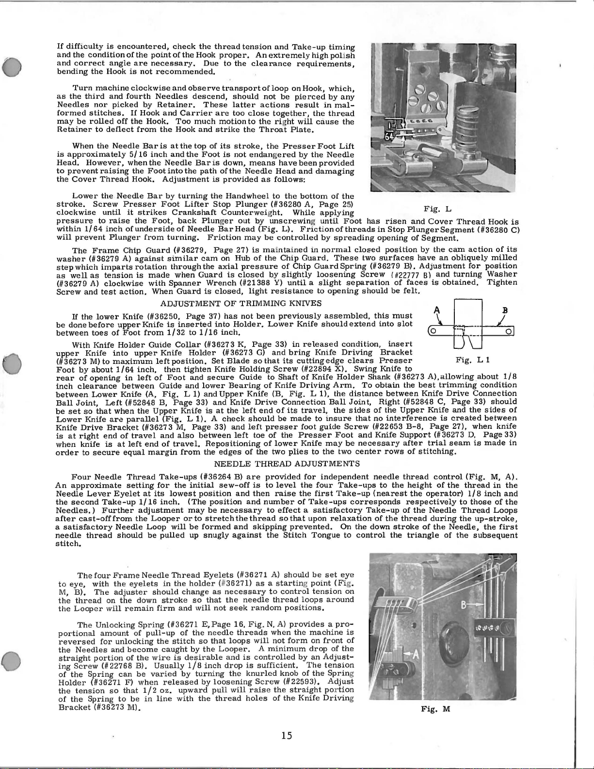
If
difficulty
and
the
and
bending
as
Needles
formed
may
Retainer
is
Head.
to
the
stroke.
clockwise
pressure
within
will
washer
step
as
(#36279
Screw
be
between
upper
(#36273
Foot
rear
inch
between
Ball
be
Lower
Knife
is
when
order
An
Needle
the
Needles.)
after
a
needle
stitch.
condition
correct
Turn
the
third
be
When
approximately
However,
prevent
Cover
Lower
1/64
prevent
The
which
well
and
If
the
done
With
Knife
by
of
clearance
Joint,
set
so
Knife
Drive
at
right
knife
to
Four
approximate
Lever
second
cast-offfrom
satisfactory
thread
is
angle
the
Hook
machine
and
nor
stitches.
rolled
to
deflect
the
raising
Thread
the
Screw
until
to
raise
inch
Plunger
Frame
(#36279
imparts
as
tension
A)
clockwise
test
lower
before
toes
of
Knife
M)to
about
opening
Lower
Left
that
are
Bracket
end
is
secure
Needle
Take-up
Further
encountered,
of
the
are
is
not
clockwise
fourth
picked
Needle
into
maximum
when
Eyelet
by
If
Hook
off
the
Hook.
from
Bar
5/16
whenthe
the
Foot
Hook.
Needle
upper
Holder
1/64
at
Needle
should
Bar
Presser
it
strikes
the
of
underside
from
Chip
Guard
A)
against similar
rotation
is
action.
Knife
(#36250,
Knife
Foot
from
upper
inch,
in
left
between
Knife
(A,
(#52848
the
parallel
(#36273
of
travel
left
end
equal
margin
Thread
setting
at
1/16
adjustment
the
Loop
be
made
with
Guide
check
point
necessary.
recommended.
Needles
Retainer.
and
the
is
inch
Needle
into
Adjustment
by
Foot
Foot,
turning.
Spanner
When
ADJUSTMENT
is
1/32
Knife
leftposition.
then
of
Foot
Guide
Fig.
B,
Upper
(Fig. L 1). A check
and
of
Take-ups
for
its
lowest
inch.
Looper
pulled
the
of
the
Hook
and
observe
descend,
Carrier
Too
much
Hook
and
at
the
top
and
the
Foot
Baris
the
path
turning
Lifter
Crankshaft
back
Plunger
of
Needle
(#36279,
when
Guard
Page
inserted
to
Collar
Holder
tighten
and
and
L 1)
Page
Knife
M,
also
travel.
from
the
initial
(The
may
or
be
up
cam
Guard
1/16
lower
33)
Page
between
(#36264
position
to
formed
through
will
Due
These
of
is
the
Stop
Friction
Page
the
Wrench
is
37)
(#36273
Set
secure
and
and
is
Repositioning
the
NEEDLE
position
be
stretch
snugly
thread
tension
proper.
to
transport
are
motion
strike
its
is
down,
of
provided
Handwheel
Counterweight.
Bar
on
axial
closed,
OF
has
into
inch.
(#36273
Blade
Knife
Upper
at
the
33)
edges
sew-off
necessary
the
clearance
should
latter
too
close
to
the
stroke,
not
endangered
means
the
Needle
Plunger
out
by
Head
may
27)
is mai
Hub
of
pressure
is
closed
(#21388
light
TRIMMING
not
Holder.
K,
Page
so
Holding
Guide
Bearing
Knife
Knife
Drive
left
should
and
left
left
toe
of
THREAD
B)
are
is
and
then
and
the
thread
and
skipping
against
An
of
not
actions
the rig
Throat
as
(Fig.
be
the
been
G)
that
of
end
presser
of
the
provided
to
number
and
Take-up
extremely
loop
be
together,
the
Presser
havebeenprovided
Head
follows:
to
(#36280
unscrewing until
L).
controlled
ntained
Chip
of
by
slightly
Y)
resistance
high poli
requirements,
on
Hook,
pierced
result
ht
Plate.
the
While
Chip
until a slight
the
will
cause
Foot
by
the
and
damaging
bottom
A,
Page
applying
Friction
by
in
normal
Guard.
Guard
loosening
to
in
KNNES
previously
Lower
33)
in
and
bring
its
Screw
to
Shaft
Knife
(B,
Fig. L 1),
Connection
of
its
be
made
of
the
lower
two
plies
ADJUSTMENTS
level
raise
to
effect a satisfactory
so
that
prevented.
the
Stitch
assembled,
Knife
should
released
Knife
cuttingedge
(#22894
of
Knife
Driving
travel,
to
foot
guide
Presser
Knife
may
to
the
for
independent
the
four
the
first
of
Take-ups
upon
Tongue
timing
sh
which,
by
any
mal-
thread
the
Lift
Needle
of
the
25)
Foot
of
threads
spreading
These
Spring
separation
opening
extend
condition,
Driving
clears
X).
Holder
Arm.
the
distance
Ball
Joint,
the
sides
insure
Screw
Foot
be
two
Take-ups
Take-up
corresponds
relaxation
On
to
has
in
opening
closed
two
(#36279
Screw
should
this
into
Swing
Shank
To
obtain
Right
of
that
no
(#22653
and
Knife
necessary
center
needle
(nearest
Take-up
of
the
down
control
risen
Stop
Plunger
position
surfaces
B).
{ #22777
of
faces
be
felt.
must
slot
insert
Bracket
Presser
Knife
to
(#36273
the
between
(#52848
the
Upper
interference
B-8,
Support
after
rows
of
thread
to
the
height
the
respectively
of
the
thread
stroke
the
triangle
Fig.
and
Cover
of
Segment.
by
the
have
an
Adjustment
B)
and
is
A),
best
trimming
Knife
C,
Knife
Page
(#36273
trial
stitching.
control
of
operator)
the
Needle
during
of
the
L
Thread
Segment
cam
obliquely
turning
obtained.
Fig.
allowing
Drive
Page
and
is
created
27),
seam
(Fig.
the
thread
to
Thread
the
Needle,
of
the
Hook
(#36280
action
of
milled
for
position
Washer
Tighten
L 1
about
condition
Connection
33)
should
the
sides
between
when
knife
D,
Page
is
made
M,
in
1/8
inch
those
of
Loops
up-stroke,
the
subsequent
is
C)
its
1/8
of
33)
in
A).
the
and
the
first
ThefourFrameNeedleThread
to
eye,
with
the
lVI,
B).
the
thread
the
Looper
The
portional
reversed
the
Needles
straight
ing
Screw
of
the
Holder
the
tension
of
the
Bracket
The
Unlocking
for
portion
Spring
(#36271
Spring
(#36273
adjuster
on
the
will
amount
unlocking
and
(#22768
can
so
that
to
eyelets
remain
of
become
of
F)
be
M).
down
Spring
pull-up
the
B).
be
varied
when
1/2
in
in
should
stroke
firm
(#36271
the
caught
wire
Usually
released
oz.
line
the
stitch
is
holder (1/
change
so
and
will
of
the
by
desirable
1/8
by
turning
upward
with
Eyelets
that
E,Page
needle
so
the
inch
by
the
(#36271
36271)
as
necessary
the
needle
not
seek
random
16,
Fig.
threads
that
loops
and
drop
the
will
will
is
controlled
is
knurled
Screw
raise
holes
Looper. A minimum
loosening
pull
thread
A)
should
as a starting point
to
control
thread
N,
A)
when
not
sufficient.
knob
the
of
the
be
tension
loops
positions.
provides a pro-
the
machine
form
on
front
drop
by
an
Adjust-
The
of
the
(#22593).
straight por
Knife
Drivin
set
eye
(Fi
around
of
the
tension
Sprin
Adjust
tion
g.
on
is
of
g
g
15
Fig.
M
 Loading...