

Page 1
MANUAL
PRT9201
STYLES
NO.
ILLUSTRATED
PARTS
LIST
36200
36200
36200
36200
36200
36200
36200
36200
36200
36200
36200
AK
PA
PH
PJ
~M
PX
TA
TH
TJ
TM
TX
a.
Finest Quality
36200
CLASS
INDUSTRIAL
SEWINGE
QUIP
MENT
Page 2
Manual
No.
PRT9201
36200
36200
33200
36200
36200
33200
Illustrated
AK
PA
PH
PJ
PM
PX
Union
for
36200
Styles
First
Copyright
Edition
By
Special
Parts
the
Series
Corporation
List
1992
36200
36200
36200
36200
36200
TA
TH
TJ
TM
TX
Rights
Reserved
Printed
March.
In
in
All
U.S.A.
1996
Countries
Page 3
PREFACE
This
parts
conjunction
It
performance.
your
lasting
This
Changes
of
On
in
Este
Cambios
de
parts
or
is
the
machine
service.
manual
in
configuration
the
following
describing
manual
endiseno
la
configuracion
manual
assemblies
with
desire
Parts
and
has
been
design
the
se
ha
has
on
Union
of
Union
listed
are
and/or
in
illustrations
pages
parts
hecho
y
la
en
been
manufactured
comprised
mejoras
prepared
the
36200
Special
Special
in
this
improvements
will
las
be
used
con
on
la
puede
ilustraciones
to
assist
Series
Adjusting
that
manual
with
on
the
may
or
part
found
the
informacion
illustrations
36200
incorporar
you
machines.
Manual
each
utmost
basis
incorporate
machine
are
designed
of
numbers.
Series
basica
una
o
numero
in
locating
INS9202.
precision
available
a
and
machines.
disponible.
pequena
de
It
can
run
at
specifically
to
slight
terminology
modificacion,
partes.
individual
be
used
its
optimum
assure
information.
modification
long
used
in
for
En
las
siguientes
en
la
descripcion
Dieses
Konstruktionsanderungen
Veranderung
Auf
Beschreibungen
warden.
den
Handbuch
der
folgenden
der
wurde
Abbildungen
paginas
de
partes
und/oder
Seiten
Teile,
encontrara
usadas
auf
finden
die
Basis
oder
in
ilustraciones
en
las
maquinas
vorhandener
Weiterentwicklungen
der
Teilenummern
Sie
die
Abbildungen
den
Maschinen
der
y
treminologia
Serie
Information
konnen
bedingen.
und
Baureihe
eine
die
36200
36200.
erstell
geringfiigige
technischen
verwendet
usada
t.
3
Page 4
1.
Before
starting
operators.
putting
of
each
the
machines
machine
described
is
only
In this
permitted
SAFETY
manual
after
taking
RULES
into
notice
service,
of
carefully
the
instructions
read
the
instructions. The
and
by
qualified
IMPORTANT! Before
2.
Observe
3.
The
it
has
conformed
Each
described
the
4. All
the
5.
Wear
6. In
case
changes
7.
The
the
sewing
description,
safety
machine
warning
machines
been
ascertained
with
machine
in
devices
safety
of
machine
are
putting
motor
national
paragraph
without
glasses.
made
hints
supplier.
the
EC
Is
only
is
not
must
conversions
at
in
the
the
safety
described
allowed
the
rules
that
the
Council
to
"STYLES
as foreseen.
be
in
position
appertaining
your
own
instructions
machine
valid
In this instruction
sewing
Directives (89/392/EEC,
be
OF
and
risk.
Into service, also
for
your
country.
manual
units
which
used as foreseen.
MACHINES"
when
safety
changes
are
marked
the
machine
devices
all
of
this
valid
with
safety
read
are
prohibited
these
is
one
sewing
Annex
The
foreseen
instruction
is
ready
prohibited.
rules
of
these
the
safety
II B).
manual.
for
must
two
rules
from
machines
use
of
Another
work
or
be
considered.
symbols:
and
being
will
the
particular
in
operation.
instructions
put
into
service
be
built
into,
machine
use,
going
Operation
Conversions
from
the
until
have
beyond
and
is
of
8.
When
doing
main
switch
8.1
When
8.2 When
dog,
8.3 When
8.4 When
8.5 When using
9.
Maintenance,
special
0.
Any
1
11. Work
12. Before
work
supervision
on
described
disconnected
disconnecting
to
be
removed
the
following
or
by
pulling
threading
replacing
needle
leaving
doing maintenance
skilled
on
of
parts
in
doing
guard,
the
clutch
repair
personnel
the
electrical
special
and
equipment
the
applicable
maintenance
from
from
compressed
by
bleeding.
the
out
needle(s),
any
parts such as
folder,
workplace
motors
and
conversion
under
skilled
the
compressed
machine
the
main
looper,
fabric
and
work.
without
consideration
equipment
personnel.
under
sections
and
repair
air
supply
has
to
be
plug:
spreader
needle(s),
guide
when
actuation
work
(see
must
electrical
of
standard
work
air
supply.
(i.e.
disconnected
etc.
presser foot,
etc.
the
workplace
lock,
item
8)
of
the
instructions.
be
done
power
sheet
on
the
pneumatic
In
pneumatic
wait
until
must
by
is
not
DIN
VDE
case
equipment
from
the
throat
is
unattended.
the
be
done
an
electrician
permitted.
0105.
equipment,
of
existing
power
plate,
motor
only
Permissible
residual
with
supply
looper,
is
stopped
by
trained
or
the
air
tank),
by
under
exceptions
machine
air
pressure,
the
turning
spreader,
totally.
technicians
direction
pressure has
has
off
to
the
feed
or
and
are
be
after
4
Page 5
1.
Ordering
Repair
Parts
CONTENTS
. . . . . . . . . . . . . . . . . . . . . . . . . . . . . . . . . . . . . . .
6
2o
3o
4o
Main
5o
Main
6o
Crankshaft
7o
Foot
8o
Detachable
9o
Differential
Torque
Oil
Sight
Eyelet
Needle
Eccentric
Illustrations
Identifying
Needles
Terms
Requirements
Frame,
Shaft
Lifter
. . . . . . . . . . . . . . . . . . . . . . . . . . . . . . . . . . . . . . . . . . . . . . . . . .
Gauges,
Parts
Bushings
Parts
&
Needle
&
Head,
Bar
Head
&
Assembly
. . . . . . . . . . . . . . . . . . . . . . . . . . . . . . . . . . . . . . . . . .
Parts
. . . . . . . . . . . . . . . . . . . . . . . . . . . . . . . . . . . . . .
. . . . . . . . . . . . . . . . . . . . . . . . . . . . . . . . . . . . . . . . . . . . . . . .
. . . . . . . . . . . . . . . . . . . . . . . . . . . . . . . . . . . . . . . . .
Top
Covers
.......................................
&
Miscellaneous
&
Miscellaneous
Lever
Tension
Head
Main
Parts
Covers,
00000000000
Feed
...............................
Parts
Bars,
&
Miscellaneous
Oiling
Needle
Feed
Dogs & Feed
Eyelet
Bar
&
Ta.ke-up
&
Cover
Lift
&
.
Parts
.
6
6
7
7
8
11
13
15
17
19
21
23
10o
11o
12o
13o
14o
15o
16o
17
18o
19o
20o
21o
Feed
Knife
Looper
Lap
Former,
Chain
Cylinder
Miscellaneous
Presser
Presser
0
Presser
Thread
Miscellaneous
Drive
Numerical
Drive
Driving
Rocker
Cutting
Feet
Feet
Foot
Stand
Unit,
Assembly,
Parts
Shaft
Miscellaneous
Knife
Bushings,
Cylinder
Feed
Rocker
&
Looper
Avoid
Parts
. . . . . . . . . . . . . . . . . . . . . . . . . . . . . . . . . . . . . . . .
&
Looper
..................................
Differential
Rocker
Cylinder
Covers
Drive
Covers,
Feed
oooooo•••················
Control
Parts
Throat
Assembly
Plates
. . . . . . . . . . . . . . . . . . . . . . . . . . . . . . . . . . . . . . . . . . . . . . .
. . . . . . . . . . . . . . . . . . . . . . . . . . . . . . . . . . . . . . . . . . . . . . .
Shoes
Gauges
Belt
Index
. . . . . . . . . . . . . . . . . . . . . . . . . . . . . . . . . . . . . . . . .
&
Guard
of
Tape
&
Parts
Reel
Table
Parts
Mounting
Parts
&
.
25
27
29
&
31
33
35
37
39
41
43
45
46
5
Page 6

ILLUSTRATIONS
ORDERING REPAIR
PARTS
This
views
may
the
manual
of
be
seen
illustration
description
shown.
Numbers
the
position
never
the
be
second
Component
indicated
main
and
20
21
22
23
24
25
26
27
sub-assembly.
the
29478CU
35851L
22729C
269
4761
39145A
22727C
various
in
the
used
parts
by
text
18
has
been
in
their
will
and
the
first
of
the
in
column.
of
indenting
below.
Looper
arranged
sections
actual
be
found a listing
number
column
part
in
of
are
the
ordering
sub-assemblies
their
As
an
Drive
Ball
Nut,
Joint,
Screw
left
Connecting
Nut,
Ball
right
Joint,
Screw
to
simplify
of
the
position
pieces
reference
illustration.
parts.
descriptions
example
Connecting
. . . . . . . . . . . . . . . . . . . . . . . . . . 2
thread
Rod
thread
. . . . . . . . . . . . . . . . . . . . . . . . . . 2
ordering
mechanism
in
the
machine.
of
the
required
numbers
Always
which
use
can
under
refer
to
Rod
upper
•••••••••••••.•.•••
•••••••••••.••••••.•
••.•••••••••••••••••••
•••••••••••••.•••••
lower
•••••••••••••••••••
repair
are
shown
parts
in
with
the
only,
The
reference
the
part
be
furnished
the
the
illustration
Assembly
parts.
so
that
On
the
their
particular
and
merely
number
for
description
••••.
the
page
part
view
number
listed
repairs
on
1
1
1
1
1
1
Exploded
parts
opposite
numbers,
being
indicate
should
in
are
of
the
page
28
It
will
The
so
the
be
ordered.
When a
usage
the
in
the
be
reason
complete
part
will
various
description
noted
is
that
upper
is
common
be
mentioned
machines
illustration.
A
numerical
back.
only
This
a
part
index
will
number
facilitate
IDENTIFYING PARTS
Where
On
an
the
construction
some
of
the
identification
smaller
ones.
PLEASE NOTE:
Part
manual
name
in
the
above
replacement
ball
to
all
in
are
not
and,
of
all
is
if
the
known.
permits,
parts
letter
is
numbers
they
and
Style
example
of
these
joint
and
machines
the
description.
the
same,
necessary,
parts
locating
each
and
on
stamped
represent
appear.
of
that
parts
lower
covered
the
the
shown
the
part
those
in
to
the
On
all
machine
the
individually
ball
However,
specific
difference
in
this
illustration
is
stamped
where
construction
distinguish
same
orders
for
which
ball
joint
in
this
manual
part,
please
studs
is
are
not
sub-assemblies
manual,
when
usage
will
and
with
will
be
is
located
description
its
does
the
part
regardless
include
the
part
not
listed.
reconunended,
should
no
specific
the
parts
be
mentioned
shown
in
at
part
from
was
not
part
number.
permit,
similar
of
which
number,
ordered.
for
the
the
when
6
Page 7

NEEDLES
Each
kind
number,
blade
and
of
118GAS
118GBS
118GHS
118GJS
118GKS
needle
of
Size
all
has
shank,
stamped
measured
number
needles
DESCRIPTION
Extra
chromium
080/032, 090/036.
Extra
shank,
Same
070/027,
Same
Sizes
Round
groove,
075/029,
both a Type
point,
on
between
represent
packed
short,
short,
chromium
as
as
available
shank,
length,
the
the
and
double
plated.needle.
single
Type
075/029,
Type
spotted,
080/032.
and
Size
groove,
needle
plated
118GBS,
118GHS,
round
shank,
shank
the
sold
065/025, 070/027,
chromium
and
complete
by
groove,
Sizes
groove,
needle.
except
080/032.
except
point,
plated
number.
finish
denotes
the
eye.
symbol
Union
struck
available
struck
with
with
extra
The
and
the
Collectively,
which
Special.
groove,
groove,
Sizes
ball
tapered
075/029.
short,
needle.
Type
other
largest
is
.060"
065/025,
spotted,
available
point.
blade
double
Sizes
number
details.
diameter
the
given
diameter
070/027,
.060"
075/029,
Sizes
and
groove,
available
denotes
The
Type
on
the
075/029,
diameter
080/032.
available
ball
070/027,
the
Size
of
the
number
label
shank,
point.
struck
36211
118GKS
118GKS
When
head
To
sample,
on
Type
TERMS
Prices
are
and
changing
before
have
the
118GKS,
forwarded
insurance.
Retainer
065/025,
75/029
80/032
needles
or
the
label.
are
net
the
the
promptly
Type
A
Size
cash
F.O.B.
needle,
070/027,
needle,
clamp
and
Size
complete
075/029".
and
shipping
no
scarf,
075/029.
APPLICATION
Recommended
36200AK, PA, PH,
Recommended
36200PX,
make
screw
and
number
order
subject
sure
is
tightened.
accurately
should
should
to
change
point.
chromium
for
for
TX
it
filled,
A
Styles
PJ,
Styles
is
fully
be
forwarded.
read
without
charge
plated.
PM,
an
as
is
TA, TH,
inserted
empty
Use
follows:
notice.
made
Sizes
TJ,
in
package,
the
description
"100
All
to
cover
available
TM
the
needle
a
needle
needles,
shipments
postage
7
Page 8
TORQUE
REQUIREMENTS
Torque
through
by a wrench,
when
amount
All
unless
tightened
Screws
set
and
straps
otherwise
requiring
(measured
a
at
distance
screwdriver,
the
proper
no
tighter.
and
eccentrics
by
hand
in
inch-pounds)
by a lever
amount
noted.
as
tightly
a
specific
etc.
should
All
torque
of
(in
Many
torque
be
tightened
other
as
possible,
is
a
inches
of
nuts,
will
rotating
these
will
be
or
feet)
devices
tighten
to
19-21
bolts,
unless
indicated
force
.
the
inch-pounds
screws,
in
This
are
part
otherwise
on
the
pounds
is
accomplished
available,
to
the
(22-24cm/kg)
etc.
illustrations.
should
noted.
applied
which
correct
be
8
Page 9
EXPLODED
AND
VIEWS
DESCRIPTION
OF
PARTS
9
Page 10
P023-9
2
10
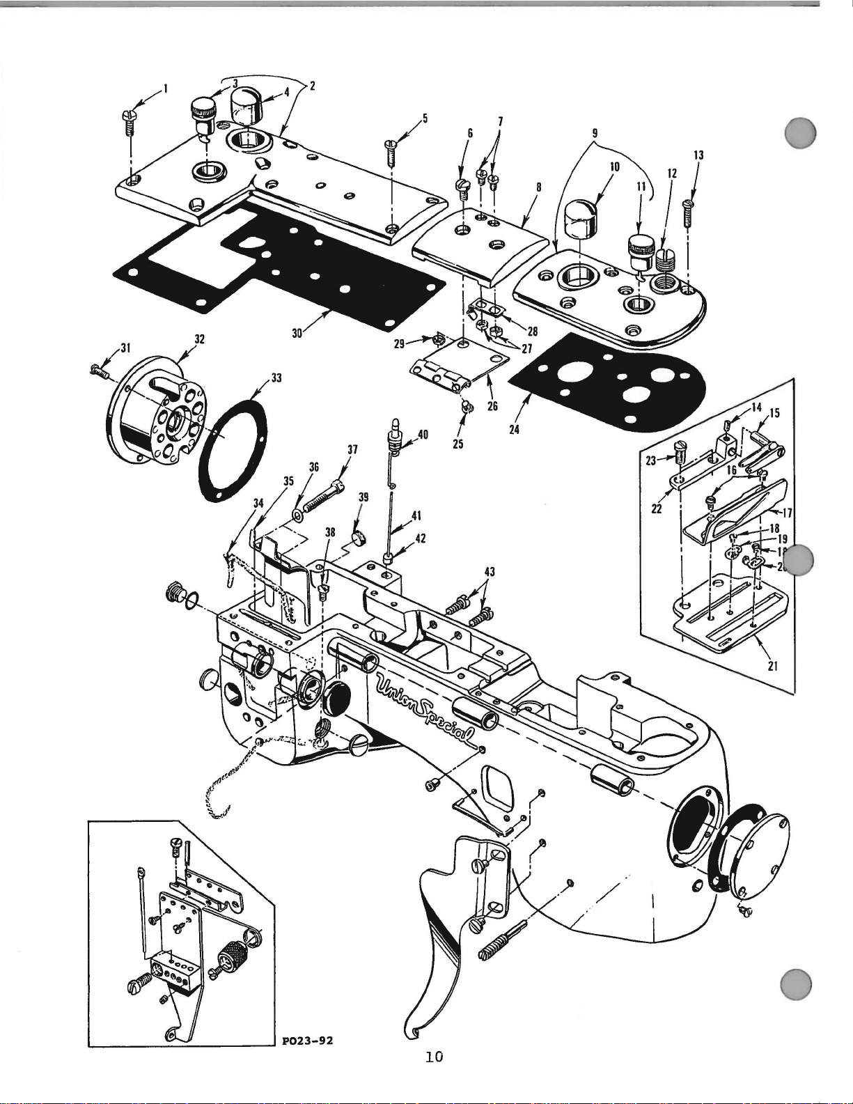
Page 11
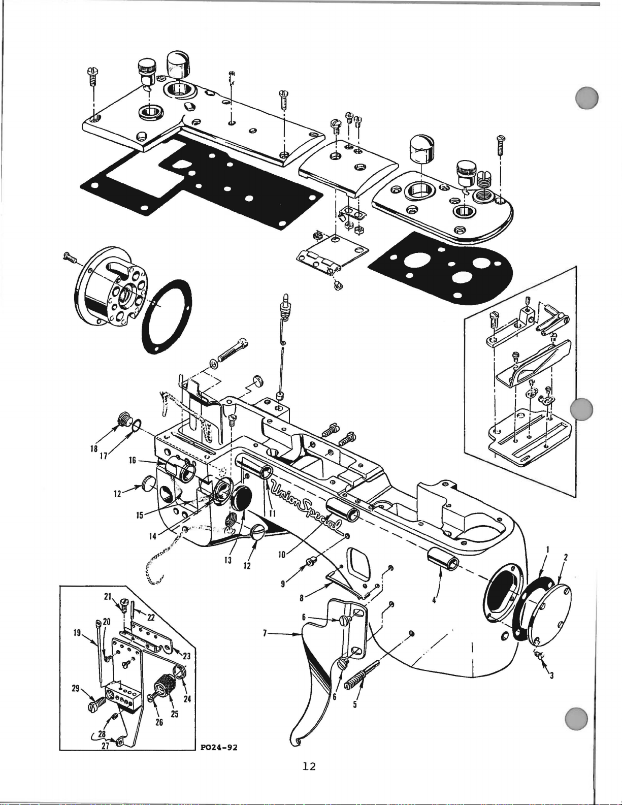
OIL
SIGHT
GAUGES,
TOP
COVERS & MISCELLANEOUS
TAKE-UP & EYELET
PARTS
Ref.
No.
10
11
12
13
14
15
16
17
18
19
20
21
22
23
24
25
26
27
28
29
30
31
32
33
34
35
36
37
38
39
40
41
42
43
1
2
3
4
5
6
7
8
9
Part
No.
93
35888
N
666-96
50-537
22516 A
93 A
90
35887 X
35887 AE
50-537
666-96
22539 M
22516 A
73 c
36256
22
KH
36204
73
A
52958 F
52958 c
36204 A
36256 A
22839
35887
AD
22564 B
35887 R
41071 G
35887 M
12934 A
35888 R
22569 B
36290
56390
E
CL21
35889 H
6042 A
22759 A
22711
22539
G
36293 B
36293 E
39593 c
93
BLK
BLK
Description
Screw,
Crank
Screw
Screw,
Screw,
Top
Top
Plug
Screw,
Screw
Cover
Screw,
cast-off
Screw,
cast-off
cast-off
cast-off
Cover
Screw
Gasket,
Screw,
Middle
Nut,
Spring,
Nut,
Gasket,
Screw,
Bushing
Gasket,
Oil
Oil
Washer,
Screw,
Screw,
Plug
Oil
Oil
Oil
Screw,
crank
Chamber
Oil
Oil
chamber
Cover
cover
.................................
. . . . . . . . . . . . . . . . . . . . . . . . . . . . . . . . . . . . . . . . 1
Cup . . . . . . . . . . . . . . . . . . . . . . . . . . . . . . . . . . . . . . . . . . . . . . . 1
Sight
Gauge . . . . . . . . . . . . . . . . . . . . . . . . . . . . . . . . . . . . . . . 1
. . . . . . . . . . . . . . . . . . . . . . . . . . . . . . . . . . . . . . . . . . . . . . . . . . . . . . 4
middl.e
spring
Cover,
Cover,
Oil
Oil
top
cover
. . . . . . . . . . . . . . . . . . . . . . . . . . . . . . . . . . . . 2
. . . . . . . . . . . . . . . . . . . . . . . . . . . . . . . . . . . . . . . . . . . . . . 2
middl.e . . . . . . . . . . . . . . . . . . . . . . . . . . . . . . . . . . . . . . . . . . 1
front ............
Sight
Gauge . . . . . . . . . . . . . . . . . . . . . . . . . . . . . . . . . . . . . . . 1
..
........
.
..................
Cup . . . . . . . . . . . . . . . . . . . . . . . . . . . . . . . . . . . . . . . . . . . . . . . 1
Screw . . . . . . . . . . . . . . . . . . . . . . . . . . . . . . . . . . . . . . . . . . . . . . . . . 1
front
top
cover
. . . . . . . . . . . . . . . . . . . . . . . . . . . . . . . . . . . . . 6
. . . . . . . . . . . . . . . . . . . . . . . . . . . . . . . . . . . . . . . . . . . . . . . . . . . . . . 1
Thread
cast
Take-up
-off
Eyelet .........
..
...........
. . .
. . . . . . . . . . . . . . . . . . . . . . . . . . . . . . . . . . . . . . . . . . . . 2
......
. . . . . . . . . . . . . . . . . . . . . . . . . . . . . . . . . . . . . . . . . . . . . . . . . . . 1
cast-off
Plate
Plate
Plate
Thread
plate
Eyelet,
Eyelet,
eyelets
.........
.
..........
rear ................................
front
..................
.
.........
.
............
. . . . . . . . . . . . . . . . . . . . . . . . . . . . . . . . . . . . . . . . . . . . . 1
Take-up
Eyelet
Holder
.........................
. . . . . . . . . . . . . . . . . . . . . . . . . . . . . . . . . . . . . . . . . . . . . . . . . . . . . . 2
front
middl.e
Cover
top
Middl.e
top
crank
bushing
Housing,
bushing
top
cover
Hinge
middl.e
middl.e
chamber
cover
top
cover
cover
cover
. . . . . . . . . . . . . . . . . . . . . . . . . . . . . . . . . . . . 1
hinge ...
. . . . . . . . . . . . . . . . . . . . . . . . . . . . . . . . . . . . . . . . . 1
spring
spring
..........
screw
..............
screw
..
...................
(90) . . . . .
..
...................
(93A)
...................
...........
. . . . . . . . . . . . . . . . . . . . . . . . . . . . . . . . . . . . . . 1
housing
includes
housing
. . . . . . . . . . . . . . . . . . . . . . . . . . . . . . . . . . . . . 1
bushing
.......
..............
.
.......
.
..................
.
.......
Wick . . . . . . . . . . . . . . . . . . . . . . . . . . . . . . . . . . . . . . . . . . . . . . . . . . . 1
Shield
. . . . . . . . . . . . . . . . . . . . . . . . . . . . . . . . . . . . . . . . . . . . . . . . . 1
for
22759 A . . . . . . . . . . . . . . . . . . . . . . . . . . . . . . . . . . . . . . . . 2
for
connecting
for
oil
wick
head
to
main
frame
.......
. . .
.........
. . . . . . . . . . . . . . . . . . . . . . . . . . . . . . . . . . . . . . . . 1
Screw . . . . . . . . . . . . . . . . . . . . . . . . . . . . . . . . . . . . . . . . . . . . . . . . . 1
Sight
Level
Gauge
Gauge . . . . . . . . . . . . . . . . . . . . . . . . . . . . . . . . . . . . . . . . . . . . 1
Indicator
Float
oil
punp
. . . . . . . . . . . . . . . . . . . . . . . . . . . . . . . . . . . . . . . . 1
. . . . . . . . . . . . . . . . . . . . . . . . . . . . . . . . . . . . . . . . . . . . 1
housing
. . . . . . . . . . . . . . . . . . . . . . . . . . . . . . . . . . . . 2
·. . 1
...
. .
..
. . 1
Amt.
Req.
5
. 1
2
1
1
1
3
. 2
1
2
1
2
11
Page 12
P024-92
12
Page 13
~N
FRAME,
BUSHINGS & MISCELLANEOUS
EYELET & COVER
PARTS
Ref.
No.
1
2
3
4
5
6
7
8
9
10
11
12
13
14
15
16
17
18
19
20
21
22
23
24
25
26
27
28
29
Part
35887
35887
22564
36290
22791
22829
36281
35781
62271
36290
35890
22539
35761
35760
CL21
36260
660-206
22733
36271
73
22768
22799
36271
36271
36271
22593
36271
28
22569
No.
A
A
A
A
B
B
G
E
H
c
D
v
z
B
B
D
D
B
E
T
D
D
B
Gasket,
End
Cover
Screw,
Main
Screw,
Screw,
Looper
Looper
Thread
Main
Crankshaft
Plug
Bushing
Needle
Oil
Needle
Rubber
Oil
Frame
Screw,
Screw,
Screw
Stitch
Unlocking
Spring
Screw
Needle
Screw,
end
Shaft
for
looper
Thread
Thread
Guide
Shaft
Screw
Lever
Wick
Lever
"0"
Drain
Needle
needle
unlocking
. . . . . . . . . . . . . . . . . . . . . . . . . . . . . . . . . . . . . . . . . 1
Unlocker
Bolder
. . . . . . . . . . . . . . . . . . . . . . . . . . . . . . . . . . . . . . . . . 1
Thread
Screw
needle
Description
end
cover
. . . . . . . . . . . . . . . . . . . . . . . . . . . . . . . . . . . . . 1
cover
Bushing,
36253B
. . . . . . . . . . . . . . . . . . . . . . . . . . . . . . . . . . 1
Bushing,
Bushing,
. . . . . . . . . . . . . . . . . . . . . . . . . . . . . . . . . . . . 2
cap
. . . . . . . . . . . . . . . . . . . . . . . . . . . . . . . . . . . 1
Shaft
. . . . . . . . . . . . . . . . . . . . . . . . . . . . . . . . . . . . . . 1
Shaft
Ring
Screw
Thread
thread
Spring
Eyelet..........................
. . . . . . . . . . . . . . . . . . . . . . . . . . . . . . . . . . . . 4
thread
. . . . . . . . . . . . . . . . . . . . . . . . . . . . . 1
. . . . . . . . . . . . . . . . . . . . . . . . . . . . . . 4
front.......
looper
thread
Shield
Guide
. . . . . . . . . . . . . . . . . . . . . . . . . . . . . . . . . 1
Wire..........
rear...........
front.....................
Bushing,
Bushing,
. .
............................
. . . . . . . . . . . . . . . . . . . . . . . . . . . . . . . 1
Eyelet....................
spring
MOunting
. . . . . . . . . . . . . . . . . . . . . . . . . . . . . . 1
drive
shield...................
. . . . . . . . . . . . . . . ...
front.............
rear..............
eyelet...................
height
Bracket..
eyelet...................
.
.............
lever
adjusting......
shaft
....
.
...........
.
..........
.
...........
. . . . 1
_ . . . . 1
.
Amt.
Req.
1
2
1
1
1
1
1
4
2
1
1
1
1
13
Page 14

II
TORQUE
19-21
in.
{22-24
em/kg)
TO
lbs.
21
'
I
P025-92
14
r------------_J
I
27--/
Page 15
MAlN
SHAFT
PARTS & MISCELLANEOUS
OILING
Ref.
No.
1
2
3
4
5
6
7
8
9
10
11
12
13
14
15
16
17
18
19
20
21
22
23
24
25
26
27
Part
No.
22585
660-207
35897
35894
21756
35897
29472
36297
35897
29472 AC
36297 M
22571 B
41071 G
22565 A
90
80265
36261 A
35861 D
35894 L
660-202
29101 J
22587 E
22894 w
29103 T
22587 E
22894 w
660-219
28 36222 c
29
30
31
32
33
34
35
36
37
38
39
22801
36223
22580
36223 A
22580
35895 y
22894
35895 X
22519 F
80265
22894 J
40 22894 K
A
BU
J
G
BW
y
J
BV
AM
p
Description
ScJ:ew,
Oil
Reservoir
Oil
Vent
Gasket
Pump
housing
Seal
Ring
Reservoir,
Screw
cover
. . . . . . . . . . . . . . . . . . . . . . . . . . . . . . . . . . . . . . . 5
. . . . . . . . . . . . . . . . . . . . . . . . . . . . . . . . . . . . . . . . . . . . . . 1
Outlet
Tube
back
. . . . . . . . . . . . . . . . . . . . . . . . . . . . . . . . . . . . . . 1
. . . . . . . . . . . . . . . . . . . . . . . . . . . . . . . . . . . . . . . . 1
. . . . . . . . . . . . . . . . . . . . . . . . . . . . . . . . . . . . . . . . . . . . . . . . . 2
. . . . . . . . . . . . . . . . . . . . . . . . . . . . . . . . . . . . . . . . . . . . . . . . . . . . . 1
Assembly
Housing
Pump
Housing
. . . . . . . . . . . . . . . . . . . . . . . . . . . . . . . . . . . . . . . . . . . . . . 1
Cover
Intake
Body
Cover
Plug
Nut
and
Oil
Tube,
Filter
and
Gear
and
Screw
. . . . . . . . . . . . . . . . . . . . . . . . . . . . . . . . . . . . . . . . . . . .
. . . . . . . . . . . . . . . . . . . . . . . . . . . . . . . . . . . . 1
Assembly...................
Oil
Tube,
. . . . . . . . . . . . . . . . . . . . . . . . . . . . . . . . . . . . . . . 1
rear......................
front
.....................
.
ScJ:ew . . . . . . . . . . . . . . . . . . . . . . . . . . . . . . . . . . . . . . . . . . . . 1
ScJ:ew,
Spacer
Take-up
Oil
Oil
Feed
take-up
Washer
Shield
Gasket
Reservoir,
Seal
Ring
Drive
Eccentric
shield
. . . . . . . . . . . . . . . . . . . . . . . . . . . . . . . . . . . . . . 2
. . . . . . . . . . . . . . . . . . . . . . . . . . . . . . . . . . . . . . . . . . . . . . 1
Assembly....................................
. . . . . . . . . . . . . . . . . . . . . . . . . . . . . . . . . . . . . . . . . . . . . . . . 1
front
. . . . . . . . . . . . . . . . . . . . . . . . . . . . . . . . . . . . . . . 1
. . . . . . . . . . . . . . . . . . . . . . . . . . . . . . . . . . . . . . . . . . . . . . 1
Assembly..............................
ScJ:ew . . . . . . . . . . . . . . . . . . . . . . . . . . . . . . . . . . . . . . . . . . . . . . . . . 2
Set
Feed
Lift
SCJ:eW
Set
Roll
Pin
Main
Shaft
SCJ:eW
Double
. . . . . . . . . . . . . . . . . . . . . . . . . . . . . . . . . . . . . . . . . . . . . . . . . . . . . . 2
Disc
Screw
Cover
ThJ:ead
Screw
Crankshaft
Screw
Main
Shaft
Screw
Eccentric
Screw
. . . . . . . . . . . . . . . . . . . . . . . . . . . . . . . . . . . . . . . . . . . . . . . . . . . 1
. . . . . . . . . . . . . . . . . . . . . . . . . . . . . . . . . . . . . . . . . . . . . 2
Assembly...............................
. . . . . . . . . . . . . . . . . . . . . . . . . . . . . . . . . . . . . . . . . . . . . . . . . 2
. . . . . . . . . . . . . . . . . . . . . . . . . . . . . . . . . . . . . . . . . . . . . 2
. . . . . . . . . . . . . . . . . . . . . . . . . . . . . . . . . . . . . . . . . . . . . . . . . 1
Take-up
. . . . . . . . . . . . . . . . . . . . . . . . . . . . . . . . . . . . . . . . 1
. . . . . . . . . . . . . . . . . . . . . . . . . . . . . . . . . . . . . . . . . . . . . . . . . 2
Take-up
. . . . . . . . . . . . . . . . . . . . . . . . . . . . . . . . . . . . . . . 1
. . . . . . . . . . . . . . . . . . . . . . . . . . . . . . . . . . . . . . . . . . . . . . . . . 2
Thrust
Collar
. . . . . . . . . . . . . . . . . . . . . . . . . . . . . . . . . . . 1
. . . . . . . . . . . . . . . . . . . . . . . . . . . . . . . . . . . . . . . . . . . . . . . . . 2
Coupling
. . . . . . . . . . . . . . . . . . . . . . . . . . . . . . . . . . . . . . . . 1
ScJ:ew . . . . . . . . . . . . . . . . . . . . . . . . . . . . . . . . . . . . . . . . . . . . . . . . . 3
Washer
Set
Spot
. . . . . . . . . . . . . . . . . . . . . . . . . . . . . . . . . . . . . . . . . . . . . . . . 3
Screw
SCJ:eW
. . . . . . . . . . . . . . . . . . . . . . . . . . . . . . . . . . . . . . . . . . . . . 4
. . . . . . . . . . . . . . . . . . . . . . . . . . . . . . . . . . . . . . . . . . . . 2
.......
..
Amt.
Req.
1
1
1
1
1
1
1
15
Page 16
r------
--
---
I
I
!
-J
19-21 in.
(22-24
23
22
P026-92
lbs.
cmfkg)
16
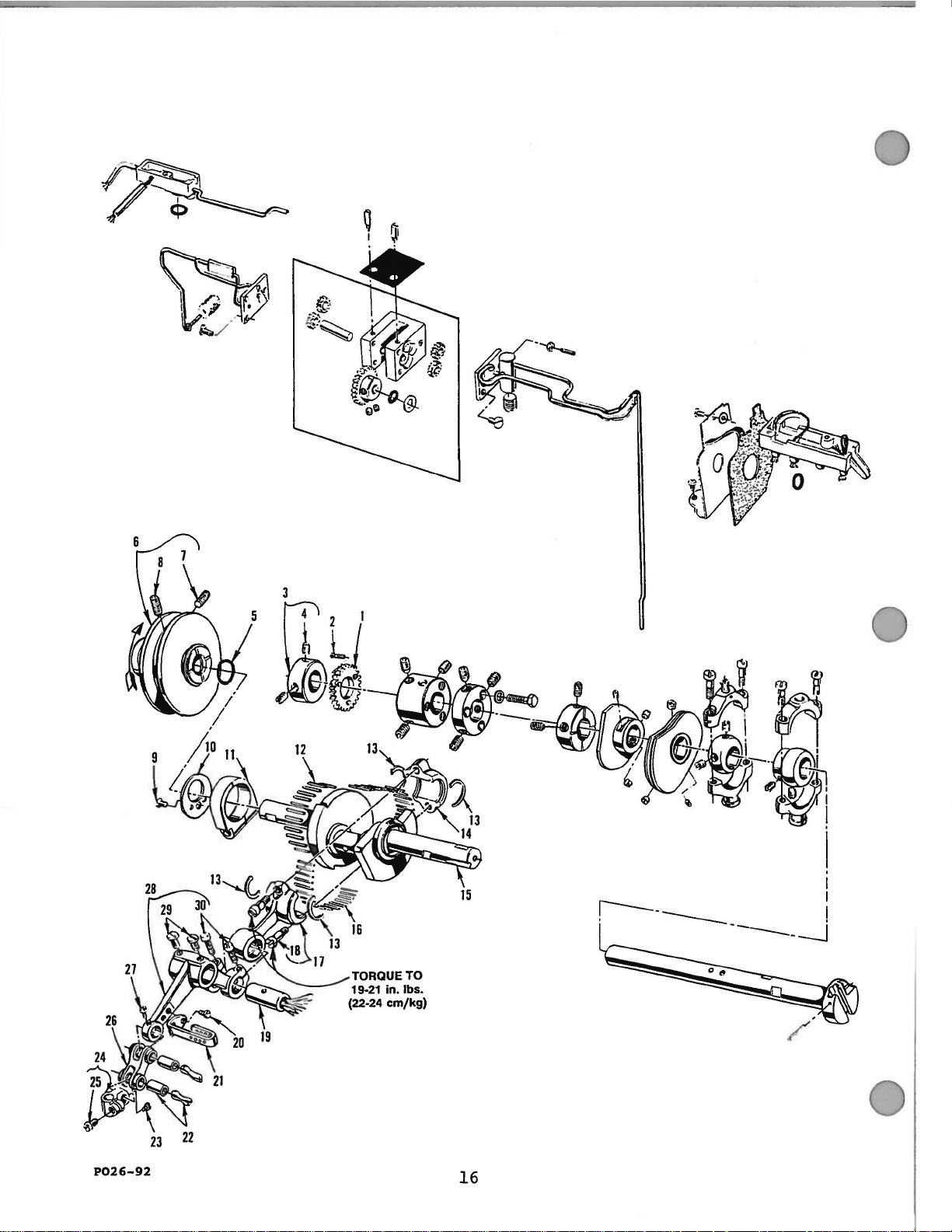
Page 17
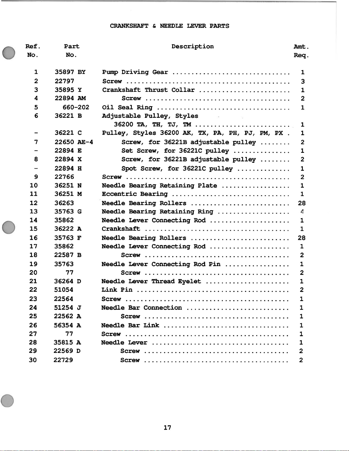
CRANKSHAFT & NEEDLE
LEVER
PARTS
Ref.
No.
1
2
3
4
5
6
7
8
9
10
11
12
13
14
15
16
17
18
19
20
21
22
23
24
25
26
27
28
29
30
Part
No.
35897
22797
35895
22894
660-202
36221
36221
22650
22894
22894
22894
22766
36251
36251
36263
35763
35862
36222
35763
35862
22587
35763
77
36264
51054
22564
51254
22562
56354
77
35815
22569
22729
BY
y
AM
B
c
AE-4
E
X
H
N
M
G
A
F
B
D
J
A
A
A
D
Description
Pump
Driving
Gear
..............................
Screw ..........................................
Crankshaft
Screw
Oil
Seal
Adjustable
36200
Pulley,
Screw,
Set
Screw,
Spot
Screw
..........................................
Needle
Eccentric
Needle
Needle
Needle
Crankshaft
Needle
Needle
Screw
Needle
Screw
Needle
Link
Screw
Pin
..........................................
Needle
Screw
Needle
Screw
..........................................
Needle
Thrust
Collar
.......................
.....................................
Ring
TA,
Styles
Screw,
Bearing
Bearing
Bearing
Bearing
Lever
. . . . . . . . . . . . . . . . . . . . . . . . . . . . . . . . . . .
Pulley,
TH,
for
for
Screw,
Styles
TJ,
TM
36200
AK,
36221B
for
36221C
36221B
for
36221C
Retaining
..........••••.........•.
TX,
adjustable
pulley
adjustable
pulley
Plate
. . . . . . . . . . . . . . . . . . .
Rollers
Retaining
Connecting
.........................
Ring
Rod
. . . . . . . . . . . . . . . . . . . . . . . . . . . . . . . . . . . . . .
Bearing
Lever
Rollers
Connecting
.........................
Rod
....................
.....................................
Lever
Connecting
Rod
Pin
.....................................
Lever
Thread
Eyelet
.....................
.......................................
Bar
Connection
..........................
.....................................
Bar
Link
Lever
. . . . . . . . . . . . . . . . . . . . . . . . . .
. . . . . . . . . . . . . . . . . . . . . . . .
Screw
Screw
.....................................
PA, PH,
PJ,
pulley
..............
pulley
.............
.................
...........
..................
....................
................
...........
PM,
.......
.......
......
PX
.
.
.
.
.
.
.
.
.
.
.
.
.
.
.
.
.
.
.
.
.
.
.
.
.
.
.
.
.
Amt.
Req.
1
3
1
2
1
1
1
2
1
2
1
2
1
1
28
1
1
28
1
2
1
2
1
2
1
1
1
1
1
1
2
2
17
Page 18

lr28
r-29
~30
~31
.
32
P027-92
!
18
"""'-"-
33
34
Page 19

FOOT
LIFTER &
TENSION
PARTS
*
*
*
*
*
*
Ref.
No.
1
2
3
4
5
6
7
8
9
10
11
12
13
14
15
16
17
18
19
20
21
22
23
24
25
26
27
28
29
30
31
32
33
34
Part
No.
36280
22585 c
36280 u
36280
22839 D
36280 T
36280
22517
36280 N
36298 F
36298 G
22652 A
36292
22517
35792 T
36292 N
22784 F
36292
22519
36280 A
36280
36280 D
C50092 s
39592
51292
51292
51292
56392 F
35792
36292 p
v
86
w
s
660-254
255
94
M
K
258 A
c
AK
F-2
F-4
F-5
109
Lifter
Screw
Presser
Screw
Lifter
Presser
c
Retaining
Screw,
Presser
Screw
Tension
Tension
Screw,
Screw,
Tension
Screw,
Tension
Tension
Spring,
Screw,
Presser
Nut
Stop
Stop
Tension
Tension
Tension
Tension
Tension
Shield,
Tension
Tension
Tension
Description
Lever
Screw
Lifter
. . . . . . . . . . . . . . . . . . . . . . . . . . . . . . . . . . . . . . . . 2
Bar
. . . . . . . . . . . . . . . . . . . . . . . . . . . . . . . . . . . . . . . . 1
Lever
Foot
presser
Foot
. . . . . . . . . . . . . . . . . . . . . . . . . . . . . . . . . . . . . . . . 1
Support
Thread
tension
tension
Plate
tension
Disc
Release
Screw
tension
stop
Foot
. . . . . . . . . . . . . . . . . . . . . . . . . . . . . . . . . . . . . . . . . . 1
Plunger
Plunger
Nut
Spring
Spring,
Spring,
Spring,
tension
Disc,
Disc,
Post
Link
. . . . . . . . . . . . . . . . . . . . . . . . . . . . . . . . . . . 2
Lever
Lifter
Connecting
Connection
Ring
Lifter
Release
. . . . . . . . . . . . . . . . . . . . . . . . . . . . . . . . . . . 1
plunger
Lifter
Segment.........................
Segment
. . . . . . . . . . . . . . . . . . . . . . . . . . . . . . . . . . 6
................................
Assembly...................
Link.......................
Lever.....................
Link.................
Lifter
. . . . . . . . . . . . . . . . . . . . . . . . . . . . . . . 2
foot
Eyelet........................
post..........................
support.......................
Bracket........................
plate
Ferrule.......................
large
small
lifter
Bearing
. . . . . . . . . . . . . . . . . . . . . . . . . . . . . . 1
bracket.................
Pin.....................
Shaft........................
release
cover
looper
needle
spring
shaft................
segment
Stop
.........................
.........................
Plunger.............
Pin.....................
thread
thread
thread
......................
Lever.........
bearing
Bracket
pin..............
................
...............
...............
bracket...
........
Amt.
Req.
. . 1
1
6
1
.
1
.
4
.
.
6
6
.
6
.
.
6
1
1
1
1
1
1
3
6
2
2
2
7
1
1
1
1
1
*
Available
on
Styles
36200 TA, TH,
TJ,
19
'I'M
and
TX
only.
Page 20

49
I
'
i
$
TORQUE
17-19 in. lbs.
(1
9-22
P028-92
TO
em/kg)
20
Page 21

DETACHABLE HEAD, HEAD COVERS, NEEDLE BAR &
NEEDLE
BAR HEAD
Ref.
No.
25
26
27
28
29
30
31
32
33
34
35
36
37
38
39
40
41
42
43
44
45
46
47
48
49
so
10
11
12
13
14
15
16
17
18
19
20
21
22
23
24
1
2
3
4
5
6
7
8
9
36289
36280
36289
36289
22524
36264
36264
36264
22738
51259
36229
36278
35859
22524
35767
35859
36251
660-261
22777
36279
36279
36279
36279
36279
22513
36294
22881
36278
35817
36278
36278
22653
36218
36218
22738
22524
36289
36289
6042
318
664
36278
22560
12538
36278
36278
36294
22585
35880
22894
28
28
28
Part
No.
B
J
E
B
E
F
c
A
B
A
D
J
D
B
B
E
G
J
A
c
A
K
E
L
B-3
J
H
A
D
A
F-16
H
A
F
M
B
c
M
J
Description
Baffl.e
Presser
Gasket,
Head
Screw,
Needl.e
Screw,
Needl.e
strike-off
Screw,
Screw,
Cover
Screw,
Detachabl.e
Screw,
Spring,
Frame
Frame
Frame
Washer,
Screw,
Oil.
Screw,
Presser
Needl.e
Presser
Presser
Screw,
Needl.e
Needl.e
Screw,
Head
Gasket,
Washer
Screw,
Taper
Presser
Screw,
Nut,
Spring,
Presser
Oil.
Screw,
Lifter
Pl.ate
Bar
front
Cover,
front
Thread
for
Thread
needl.e
for
Thread
needl.e
Presser
Needl.e
Screw
Sewing
Needl.e
Cover
Retaining
frame
frame
Chip
Chip
Chip
frama
oil.
Defl.ector
right
Foot
Bar
Bar
Foot
l.eft
Head,
Head,
Screw,
l.eft
Cover,
l.eft
for
Pin
Bar
presser
presser
presser
Bar
Guard
oil.
Lever
Screw........................................................
. . . . . . . . . . . . . . . . . . . . . . . . . . . . . . . . . . . . . . . . . . . . . . . . . 1
Lifter
front
head
needl.e
Pin
cover
Eyel.et,
Sewing
Bar
Bar
.....................................................
Head
Bar
Thread
chip
Guard,
Guard,
Guard,
chip
defl.ector
. . . . . . . . . . . . . . . . . . . . . . . . . . . . . . . . . . . . . . . . . . . . . . . . . . . . 1
presser
Guide,
• . • • • . . . . . • • • • • • . • • . • • • . • • • • • • . • . • . . • . • . • • • • . • . • • • • . • . 1
. . . . . . . . . . . . . . . . . . . . . . . . . . . . . . . . . . . . . . . . . . . . . . . . . . . . . 1
Guide,
presser
al.l.
styl.es
for
needl.es
head
l.eft
head
connecting
. . . . . . . . . . . . . . . . . . . . . . . . . . . . . . . . . . . . . . . . . . . . . . . . . . . . . 1
Guide
bar
Regul.ating
. . . . . . . . . . . . . . . . . . . . . . . . . . . . . . . . . . . . . . . . . . . . . . . . . . . . . . 1
guard
Link
Lever
head
cover
. . . . . . . . . . . . . . . . . . . . . . . . . . . . . . . . . . . . . . . . . . . . 1
cover
strike-off
thread
Take-up,
Hol.der
thread
thread
thread
Head
Bushing
Bushing,
Key
. . . . . . . . . . . . . . . . . . . . . . . . . . . . . . . . . . . . . . . . . . . 2
Bushing,
carrier
Ring
guard
chip
guard
styl.es
styl.es
styl.es
guard
. . . . . . . . . . . . . . . . . . . . . . . . . . . . . . . . . . . . . . . . . . . . . 1
right
l.eft
foot
styl.es
36200
and
cover
..........................................
............................................
cover
stud
bar
guide
guide
bar
. . . . . . . . . . . . . . . . . . . . . . . . . . . . . . . . . . . . . . . . . . . . . . 1
Connection
. . . . . . . . . . . . . . . . . . . . . . . . . . . . . . . . . . . . . 1
. . . . . . . . . . . . . . . . . . . . . . . . . . . . . . . . . . . . . 1
. . . . . . . . . . . . . . . . . . . . . . . . . . . . . . . . . . . . . . . 2
Pin
take-up
compl.ete
. . . . . . . . . . . . . . . . . . . . . . . . . . . . . . . . . . . . . . . . . 1
take-up
eyel.et
al.l.
styl.es
take-up
. . . . . . . . . . . . . . . . . . . . . . . . . . . . . . . . . . . . . . . 1
. . . . . . . . . . . . . . . . . . . . . . . . . . . . . . . . . . . . . . . 1
upper
l.ower
and
. . . . . . . . . . . . . . . . . . . . . . . . . . . . . . . . . . . . . . . . . 1
.....................................
. . . . . . . . . . . . . . . . . . . . . . . . . . . . . . . . . . . . . 1
36200
36200
36200
• • . . • • . . . . . . . . • . . • • • . • . . . . • • • • . . . . . . . . . . . . 1
foot
guide
. . . . . . . . . . . . . . . . . . . . . . . . . . . . . . . . . . . . . . . . 1
. . . . . . . . . . . . . . . . . . . . . . . . . . . . . . . . . . . . . 1
guide
except
PJ,
retainer
. . . . . . . . . . . . . . . . . . . . . . . . . . . . . . . . . . . . . . . 1
head
to
. . . . . . . . . . . . . . . . . . . . . . . . . . . . . . . . . . . . . . . . 1
stud
stud
. . . . . . . . . . . . . . . . . . . . . . . . . . . . . . . . . . . . . . . . . . 1
Screw
. . . . . . . . . . . . . . . . . . . . . . . . . . . . . . . . . . . . 1
Amt.
Req.
. . . . . . . . . . . . . . . . . . . . . . . . . . . . . . . . . 4
.............................
. . . . . . . . . . . . . . . . . . . . . . . . . . . . . . 1
. . . . . . . . . . . . . . . . . . . . . . . . . . . . . . . . . 2
. . . . . . . . . . . . . . . . . . . . . . . . . . . . . . . 1
except
. . . . . . . . . . . . . . . . . . . . . . . . . . . . . . . . . 4
. . . . . . . . . . . . . . . . . . . . . . . . . . . . . . . . . 1
. . . . . . . . . . . . . . . . . . . . . . . . . . . . . . . . . 1
Hook
Driving
PX,
AK
. . . . . . . . . . . . . . . . . . . . . . . . . . . . . . 1
PA, PH,
. . . . . . . . . . . . . . . . . . . . . . . . . . . . . . 1
. . . . . . . . . . . . . . . . . . . . . . . . . . . . . . . . . . . . 2
35200
PM,
. . . . . . . . . . . . . . . . . . . . . . . . . . . . . . 5
main
................................
...................................
..................................
36200
TX
........................
PJ,
PM,
PJ,
PM,
TJ,
TM
frame
PX,
TX
Sl.eeve
onl.y
.....................
TA,
TJ,
TH,
Bushing
TJ,
TM
................
..........
TM
. . . . . . 1
........•..
. . . . . . 1
.
.
.
1
2
1
2
1
1
1
4
1
1
1
1
1
1
21
Page 22

7
TORQUE TO
19-21 in. lbs.
(22-24
cmfkg)
2
4
4
57/64"
(124.2mm)
55/64"
(123.4mm)
P029-92
22
Page 23

DIFFERENTAL
& MAIN FEED
BARS,
FEED DOGS & FEED
LIFT
ECCENTRIC
ASSEMBLY
Ref.
No.
10
11
12
13
14
15
16
17
18
19
20
21
22
23
24
25
26
27
28
29
30
31
32
Part
No.
1
2
3
4
5
6
7
8
9
22845
36236
36234
36234
36234
22587
22528
36226
36226
36226
36226
36225
22528
36205
36205
36205
36205
36234
22578
36234
36234
36236
36236
33174
36236
62238
29478
29103
22894
22587
36244
36244
22729
41255
22747
87
269
18
M
F
D
F
G
H
A
B
H
J
u
A
B
H
J
E
H
G
c
H
G
B
E
A
cs
T
w
E
A
c
B
Screw,
Differential
Feed
Differential
Screw,
Differential
Differential
Differential
Differential
Screw,
Needle
Screw,
Main
Main
Main
Main
Main
Feed
Bushing
Driving
Screw
Main
Link
Feed
differential
Bar
Feed
Screw
differential
Styles
.050"
.050"
need1e
Guard,
main
Feed
Styles
Feed
Feed
step
Feed
step
Feed
Screw
Feed
Bar
Link
. . . . . . . . . . . . . . . . . . . . . . . . . . . . . . . . . . . . . . . . . . . . . . . . . . . . . . . . . . 1
Feed
Pin
Lift
Feed
Nut,
Connecting
Nut,
Ball
Ball
Screw,
Eccentric
Bar
. . . . . . . . . . . . . . . . . . . . . . . . . . . . . . . . . . . . . . . . . . . . . . . . . . . . . 2
36200
(1.27mm)
(1.27mm)
feed
Dog,
36200
Dog,
Dog,
on
right
Dog,
on
right
Bar
. . . . . . . . . . . . . . . . . . . . . . . . . . . . . . . . . . . . . . . . . . . . . . . . . . . . . 2
Bar
Slide
.................
Bar
. . . . . . . . . . . . . . . . . . . . . . . . . . . . . . . . . . . . . . . . . . . . . . . . . . . . . . . 1
Eccentric
Lift
Set
Screw
left
right
Joint,
Screw
Fork
ball
Description
feed
bar
driving
Feed
Bar
Driving
Stud
. . . . . . . . . . . . . . . . . . . . . . . . . . . . . . . . . . . . . . . . 1
Feed
Bar
. . . . . . . . . . . . . . . . . . . . . . . . . . . . . . . . . . . . . . . . . . 1
Plate
Feed
Feed
Feed
Feed
guard
all
marked
marked
marked
marked
. . . . . . . . . . . . . . . . . . . . . . . . . . . . . . . . . . . . . . . . . . . . . . . . . . 1
Plate
Block
Stud
Drive
Eccentric
Screw
thread
. . . . . . . . . . . . . . . . . . . . . . . . . . . . . . . . . . . . . . . . . . . . . . . . . 1
. . . . . . . . . . . . . . . . . . . . . . . . . . . . . . . . . . . . . . . . . . . . 1
feed
Dog,
marked
AK,
PA,
PJ,
Dog,
marked
Dog,
marked
step
on
Dog,
marked
step
on
. . . . . . . . . . . . . . . . . . . . . . . . . . . . . . . . . . . . . . . . . . . . 1
Styles
dog
. . . . . . . . . . . . . . . . . . . . . . . . . . . . . . . . . . . . . . . . . . . 1
"PK",
AK,
PA,
PJ,
"PL",
"PR",
side,
side,
. . . . . . . . . . . . . . . . . . . . . . . . . . . . . . . . . . . . . . . . . . . . . . . . 2
Rod
thread
complete
. . . . . . . . . . . . . . . . . . . . . . . . . . . . . . . . . . . . . . . . . . . . . . . . 2
fork
styles
"W",
Styles
. . . . . . . . . . . . . . . . . . . . . . . . . . . . . . . . . . . . . . . . . . . . 1
. . . . . . . . . . . . . . . . . . . . . . . . . . . . . . . . . . . . . . . . . . . 1
. . . . . . . . . . . . . . . . . . . . . . . . . . . . . . . . . . . . . . . . . . . . . . 2
Link
Assembly...........
Assembly
. . . . . . . . . . . . . . . . . . . . . . . . . . . . . . . . . . . . . . . . . . . . 2
. . . . . . . . . . . . . . . . . . . . . . . . . . . . . . . . . . . . . . . . . . 1
. . . . . . . . . . . . . . . . . . . . . . . . . . . . . . . . . . . . . . . . . . . . 1
. . . . . . . . . . . . . . . . . . . . . . . . . . . . . . . . . . . . . . . . . 1
. . . . . . . . . . . . . . . . . . . . . . . . . . . . . . . . . . . . . . . . . . 1
Link......
dog............
"FV",
PX, TA,
"PB",
"PQ",
right
"W",
right
. . . . . . . . . . . . . . . . . . . . . . . . . . . . . . . . . . . . . . . 1
14
teeth
PX, TA,
16
teeth
14
teeth
36200
16
teeth
36200
..
. .
...
. . . . . . . . . . . . . . . . . . . . . . . . . . . . . . . . . . . . . . . 1
. . . . . . . . . . . . . . . . . . . . . . . . . . . . . . . . . . . . . . 1
link......................
14
teeth
TJ,
TX.............
16
teeth
14
teeth
side,
side,
. . . . 0
Styles
16
teeth
Styles
per
TJ,
per
per
PH,
per
PM,
.............
Ball
Joint.....
TX..............
TH
TM
.
.
......
.
......
inch,
inch
inch,
inch,
.
...............
.
..........
per
inch,
per
inch
per
inch,
36200
per
36200
.....
..
...................
PH,
inch,
PM,
. . . . . . . . . . . . . . . . . . 1
.050"
. . .
....
.050"
0.............
.......................
.
.............
. . . . . 1
.
.......
. . . . . . . . . . 1
TH
'1M
.
.......
(1.27mm)
....
(1.27mm)
. 1
.....
Amt.
Req.
1
1
1
1
1
1
1
2
1
1
23
Page 24

-
.. ..
L~
24°
~o·
·
-
.
.,
4
4
57/64"
(124.2mm)
55/64"
(123.4mm)
P030-92
24
Page 25

FEED
DRIVE
ASSEMBLY,
FEED
ROCKER & LOOPER
AVOID
PARTS
Ref.
Part
No. No.
1
660-207
2 36236 A
3
4
5
36237
36237 A
22504 c
6 36236 J
7 36236
8 36236
9
10
11
77
36236 B
660-206
12 22711
13
14
15
16
17
29478
29101 J
22587 E
22894 w
269
18 43246
19
20
21
22
23
18
35846
22729 c
35846 B
35866
24 36236 B
25
26
660-206
22711
27 35766 B
28 35842 J
29
30
31
36236 A
660-207
35836 c
32 36236 H
33
34
35
36
258
6042 A
36236
62238 A
37 29478
38
39
35851
56341 F
40 35851 M
K
CT
c
DM
K
Oil.
Seal
Feed
Rocker
Differential
Differential
Screw
. . . . . . . . . . . . . . . . . . . . . . . . . . . . . . . . . . . . . . . . . . . . . . . . . . . . . . 1
Differential
Differential
Feed
Rocker
Screw
Bushing
Oil.
Screw
Feed
. . . . . . . . . . . . . . . . . . . . . . . . . . . . . . . . . . . . . . . . . . . . . . . . . . . . . . 2
. . . . . . . . . . . . . . . . . . . . . . . . . . . . . . . . . . . . . . . . . . . . . . . . . . . . 1
Seal
. . . . . . . . . . . . . . . . . . . . . . . . . . . . . . . . . . . . . . . . . . . . . . . . . . . . . . 1
Drive
Feed
Nut,
Connecting
Nut,
Ball.
Description
Ring
. . . . . . . . . . . . . . . . . . . . . . . . . . . . . . . . . . . . . . . . . . . . . . 1
Shaft
Feed
Feed
Driving
Feed
. . . . . . . . . . . . . . . . . . . . . . . . . . . . . . . . . . . . . . . . . . 1
Adjusting
Adjusting
Link
Driving
Lever..........................
Link...........................
Stud.............................
Link
Slide
Bl.ock
.......
..........
. . . . . . . . . . . . . . . . . . . . . . . . . . . . . . . . . . . . . . . . . . . . . . . . 1
Ring
. . . . . . . . . . . . . . . . . . . . . . . . . . . . . . . . . . . . . . . . . . . . . . 1
Assembly
Drive
Screw
Set
Screw
left
thread
. . . . . . . . . . . . . . . . . . . . . . . . . . . . . . . . . . . . . . . . 1
Eccentric
Assembl.y
.....
....................
. . . . . . . . . . . . . . . . . . . . . . . . . . . . . . . . . . . . . . . . . . . . 2
. . . . . . . . . . . . . . . . . . . . . . . . . . . . . . . . . . . . . . . . 2
. . . . . . . . . . . . . . . . . . . . . . . . . . . . . . . . . . . . . . 1
Rod . . . . . . . . . . . . . . . . . . . . . . . . . . . . . . . . . . . . . . . . 1
right
Joint
thread
. . . . . . . . . . . . . . . . . . . . . . . . . . . . . . . . . . . . . 1
. . . . . . . . . . . . . . . . . . . . . . . . . . . . . . . . . . . . . . . . . . . . 1
Amt.
Req.
Screw . . . . . . . . . . . . . . . . . . . . . . . . . . . . . . . . . . . . . . . . . . . . 2
Washer . . . . . . . . . . . . . . . . . . . . . . . . . . . . . . . . . . . . . . . . . . . . . . . . . . . . . 1
Nut
. . . . . . . . . . . . . . . . . . . . . . . . . . . . . . . . . . . . . . . . . . . . . . . . . . . . . . . . 1
Bushing
Oil.
Screw
Nut
Feed
Feed
Oil.
Screw,
Bushing
Nut
. . . . . . . . . . . . . . . . . . . . . . . . . . . . . . . . . . . . . . . . . . . . . . . . . . . . 1
Seal.
Ring
. . . . . . . . . . . . . . . . . . . . . . . . . . . . . . . . . . . . . . . . . . . . . . 1
. . . . . . . . . . . . . . . . . . . . . . . . . . . . . . . . . . . . . . . . . . . . . . . . . . . . . . 1
. . . . . . . . . . . . . . . . . . . . . . . . . . . . . . . . . . . . . . . . . . . . . . . . . . . . . . . . 1
Drive
Drive
Seal
Ring
feed
and
Looper
Shaft
Avoid
Drive
Lever....................
. . . . . . . . . . . . . . . . . . . . . . . . . . . . . . . . . . . . . . . . . . . 1
. . . . . . . . . . . . . . . . . . . . . . . . . . . . . . . . . . . . . . . . . . . . . . 1
rocker
driving
link...........................
. 1
. . . . . . . . . . . . . . . . . . . . . . . . . . . . . . . . . . . . . . . . . . . . . . . . . . . . 1
..
. . . .
..
. . . . . . . . . . . . . .
..
..
. .
..
. . . . . . . . . . . .
.. ..
. . . . . . . .
..
Washer . . . . . . . . . . . . . . . . . . . . . . . . . . . . . . . . . . . . . . . . . . . . . . . . . . . . . 1
Feed
Rocker
Link
Pin
Looper
Driving
Link
. . . . . . . . . . . . . . . . . . . . . . . . . . . . . . . . . . . 1
. . . . . . . . . . . . . . . . . . . . . . . . . . . . . . . . . . . . . . . . . . . . . . . . . . . 1
Drive
Shaft
Cross
Head
Connecting
Rod
Assembly
. . . . . . 1
Screw . . . . . . . . . . . . . . . . . . . . . . . . . . . . . . . . . . . . . . . . . . . . . . . . . 2
Ferrule
Connecting
. . . . . . . . . . . . . . . . . . . . . . . . . . . . . . . . . . . . . . . . . . . . . . . 2
Rod
. . . . . . . . . . . . . . . . . . . . . . . . . . . . . . . . . . . . . . . . 1
1
1
1
1
1
1
1
25
Page 26

TORQUE
19-21 in.
(22-24
em/kg)
TO
lbs.
3
5/32"
(80.2mm)
P031-92
26
Page 27

KNIFE
DRIVING
PARTS
Ref.
Part
No. No.
1 36251 B
2
3
12934 A
52848 B
4 22729
5
6
7
8
9
10
11
12
13
14
15
16
17
18
19
18
36251
97
36278 J
22585
36278 H
52841 H
660-202
36261
52848 c
36 G
22729 c
269
12934 A
4761
20 36251 c
36251 v
21
22
23
24
25
26
27
22585
36273 M
36273 F
36273 N
605 A
36273 J
660-219 D
28 36273
29
30
31
32
33
34
35
36
36273 K
22729 M
22799 N
36273 D
36270
36273 G
22894 X
22767 A
37 36273 A
38
1096
c
p
A
c
B
Description
Cover
Nut
Knife
Nut,
Cover
Presser
Presser
Nut
Oil
Knife
Knife
. .
Rod
.. ..
Seal
Thread
..
. . . . . . . . . . . .
Drive
Screw
right
Connection
. . . . . . . . . . . . . . . . . . . . . . . . . . . . . . . . . . . . . . . . . . . . . . . . . . . 2
thread
Thread
Ball
Joint
Screw
Screw
. . . . . . . . . . . . . . . . . . . . . . . . . . . . . . . . . . . . . . . . . . . . . . . . . . . 2
Bar
Guide
. . . . . . . . . . . . . . . . . . . . . . . . . . . . . . . . . . . . . . . . . . . . . . . . . . . 1
Bar
Guide
..
. . . . . .
Ring
Drive
Drive
Lever
Connection
Carrier
and
Hook
..
. . . . . . . . . . . .
Ball
Joint,
Driving
..
left
Sleeve.................
. . . .
..
. .
..
.. ..
......................
. .
.. .. ..
. . . . . . . . . . . . . . . . . . . . . . . . . . . . . . . . . . . . . . . . . . . . 1
Carrier
and
Hook
Driving
Connection
. . . . . . . . . . . . . . . . . . . . . . . . . . . . . . . . . . . . . . . . . . . . 1
. . . . . . . . . . . . . . . . . . . . . . . . . . . . . . . . . . . . . . . . . . . . 1
Stud
. . . . . . . . . . . . . . . . . . . . . . . . . . . . . . . . . . . . . . . 1
..
. . . . . .
.. ..
. .
..
. .
..
. . . . . . . .
.. ..
. . . .
..
. .
. . . . . . . . . . . . . . . . . . . . . . . . . . . . . . . . . . . . . . . . . . . . . . . . 1
. . . . . . . . . . . . . . . . . . . . . . . . . . . . . . . . . . . . . . . . . . . . 1
Ball
Joint,
right.....................
Washer . . . . . . . . . . . . . . . . . . . . . . . . . . . . . . . . . . . . . . . . . . . . . . . . . . 1
Nut,
Nut
Knife
Sleeve
Sleeve
Knife
Roll
Knife
Knife
Screw
Knife
Knife,
Knife
Screw
Screw
Knife
Screw
left
..
Drive
Screw
Driving
Bushing
Bushing
Screw
Knife
Pin
Holder
Holder
Screw
Support
Holder
. . . . . . . . . . . . . . . . . . . . . . . . . . . . . . . . . . . . . . . . . . . . . . . . . . . . . . . . 2
Holder
Screw
. . . . . . . . . . . . . . . . . . . . . . . . . . . . . . . . . . . . . . . . . . . . . . . . . . . 2
thread
..
. . . .
Driving
Driving
. . . . . . . . . . . . . . . . . . . . . . . . . . . . . . . . . . . . . . . . . . . . . 1
..
..
. . . .
..
..
Connecting
Lever,
Lever,
. . . . . .
Rod...................................
Styles
Styles
..
. . . . . . . . . .
36200
36200
AK,
PJ,
PA,
PM,
..
PH,
TJ,
.. ..
..
PX,
T.M
.. ..
. .
TA, TH,
............
. . . . . . . . . . . . . . . . . . . . . . . . . . . . . . . . . . . . . . . . . . . . . . . . . . . 1
Bracket
. . . . . . . . . . . . . . . . . . . . . . . . . . . . . . . . . . . . . . . . . . . . . . . . . 1
. . . . . . . . . . . . . . . . . . . . . . . . . . . . . . . . . . . . . . . . . . . . . . . . . 1
. . . . . . . . . . . . . . . . . . . . . . . . . . . . . . . . . . . . . . . . 1
. . . . . . . . . . . . . . . . . . . . . . . . . . . . . . . . . . . . . . . . . . . . . . . . . . . 2
Holder
Guide
Plate
. . . . . . . . . . . . . . . . . . . . . . . . . . . . . . . . 1
. . . . . . . . . . . . . . . . . . . . . . . . . . . . . . . . . . . . . . . . . . . . . . . . . . . . . 2
Spring
Guide
. . . . . . . . . . . . . . . . . . . . . . . . . . . . . . . . . . . . . . . . . . 1
Collar....................................
. . . . . . . . . . . . . . . . . . . . . . . . . . . . . . . . . . . . . . . . . . . . . . . . . . . 1
. . . . . . . . . . . . . . . . . . . . . . . . . . . . . . . . . . . . . . . . . . . . . . . . . . . . . . . . 1
. . . . . . . . . . . . . . . . . . . . . . . . . . . . . . . . . . . . . . . . . . . . . . . . 1
upper
. . . . . . . . . . . . . . . . . . . . . . . . . . . . . . . . . . . . . . . . . . . . . . . . . 1
. . . . . . . . . . . . . . . . . . . . . . . . . . . . . . . . . . . . . . . . . . . . . . . . . 1
. . . . . . . . . . . . . . . . . . . . . . . . . . . . . . . . . . . . . . . . . . . . . . . . . . . . . . . . 1
Shank . . . . . . . . . . . . . . . . . . . . . . . . . . . . . . . . . . . . . . . . . . . 1
. . . . . . . . . . . . . . . . . . . . . . . . . . . . . . . . . . . . . . . . . . . . . . . . . . . 1
. . . . 1
..
..
. . 1
..
. . . . 1
TX
Amt.
Req.
1
1
1
1
1
1
1
27
Page 28

TORQUE TO
19-21 in. lbs.
(22-24
em/kg)
36
3
5/32"
(80.2mm)
20
15
P032-92
28
17
Page 29

LOOPER
ROCKER
SHAFT & LOOPER
ROCKER
DRIVE
PARTS
Ref.
No.
1
2 604
3
4
5
6
7
8
9
10
11
12
13
14
15
16
17
18
19
20
21
22
23
24
25
26
27
28
29
30
31
32
33
34
35
36
37
38
39
40
41
42
43
Part
No.
36210
36208 A
22585
A
36248
1096
B
22564
D
22652 A-6
36249
35751
G
22572 B
36249
652
B
C-9
22729 D
36278 c
41255 B
22747
36253
B
660-221
29478
35851
22729
cu
L
c
269
4761
18
39145
A
22729 c
12865
88
15037
36253
A
A
258 A
77
52336
660-215
22795
36253
29478
36253
36253
B
G
DR
J
H
660-311
20
269
Description
Looper
Screw,
Looper
Screw
Looper
Looper
Looper
Looper
Guide
Ball
Screw
Looper
Oil
Looper
Collar
NUt
Looper
NUt
Screw
Link
Retaining
Screw
Looper
Looper
Mounted
needl.e
Needl.e
guard
Guard,
marked
"FZ" . . . . . . . . . . . . . . . . . . . . 1
. . . . . . . . . . . . . . . . . . . . . . . . . . . . . . . . . . . . . . . . . 2
. . . . . . . . . . . . . . . . . . . . . . . . . . . . . . . . . . . . . . . . . . . . . . . . . . . . . . 1
. . . . . . . . . . . . . . . . . . . . . . . . . . . . . . . . . . . . . . . . . . . . . . . . . . . . . . . 1
Holder
Looper
Screw
Screw
Rocker
Shaft
Screw
Shaft
Washer
Screw
Stud
Fork
. . . . . . . . . . . . . . . . . . . . . . . . . . . . . . . . . . . . . . . . . . . . . . . 1
Adjusting
Screw.................................
. . . . . . . . . . . . . . . . . . . . . . . . . . . . . . . . . . . . . . . . . . . . . . . . . . 1
. . . . . . . . . . . . . . . . . . . . . . . . . . . . . . . . . . . . . . . . . . . . . . . . . . 1
Shaft
Collar
. . . . . . . . . . . . . . . . . . . . . . . . . . . . . . . . . . . . . . . . . 1
. . . . . . . . . . . . . . . . . . . . . . . . . . . . . . . . . . . . . . . . . 1
. . . . . . . . . . . . . . . . . . . . . . . . . . . . . . . . . . . . . . . . . . . . . . . . . . 1
Sleeve
. . . . . . . . . . . . . . . . . . . . . . . . . . . . . . . . . . . . . . . . . 1
. . . . . . . . . . . . . . . . . . . . . . . . . . . . . . . . . . . . . . . . . . . . . . . . . 1
. . . . . . . . . . . . . . . . . . . . . . . . . . . . . . . . . . . . . . . . . . . . . . . . . . 1
. . . . . . . . . . . . . . . . . . . . . . . . . . . . . . . . . . . . . . . . . . . . . . . . . . 1
. . . . . . . . . . . . . . . . . . . . . . . . . . . . . . . . . . . . . . . . . . . . . . . . . . . 1
. . . . . . . . . . . . . . . . . . . . . . . . . . . . . . . . . . . . . . . . . . . . . . . . . . . . . . . 1
Drive
Seal
Drive
Ball
Nut,
Connecting
Nut,
Ball
Lever
Ring
Connecting
Joint,
Screw
left
right
Joint,
Screw
Shaft
. . . . . . . . . . . . . . . . . . . . . . . . . . . . . . . . . . . . . . . . . . . . . . . 1
upper
. . . . . . . . . . . . . . . . . . . . . . . . . . . . . . . . . . . . 1
Rod
Assembly........................
. . . . . . . . . . . . . . . . . . . . . . . . . . . . . . . . . . . . . . 1
. . . . . . . . . . . . . . . . . . . . . . . . . . . . . . . . . . . . . . . . . . . . . 2
thread
. . . . . . . . . . . . . . . . . . . . . . . . . . . . . . . . . . . . . . . 1
Rod . . . . . . . . . . . . . . . . . . . . . . . . . . . . . . . . . . . . . . . . . 1
thread
lower
. . . . . . . . . . . . . . . . . . . . . . . . . . . . . . . . . . . . . . 1
. . . . . . . . . . . . . . . . . . . . . . . . . . . . . . . . . . . . . . 1
. . . . . . . . . . . . . . . . . . . . . . . . . . . . . . . . . . . . . . . . . . . . . 2
. . . . . . . . . . . . . . . . . . . . . . . . . . . . . . . . . . . . . . . . . . . . . . . . . . . . . . 2
Screw
. . . . . . . . . . . . . . . . . . . . . . . . . . . . . . . . . . . . . . . . . . . . . . . . . . . . . . . . . 1
. . . . . . . . . . . . . . . . . . . . . . . . . . . . . . . • . . . . . . . . . . . . . . . . . . . • . . . . . 1
. . . . . . . . . . . . . . . . . . . . . . . . . . . . . . . . . . . . . . . . . . . . . . . . . . 2
Drive
Lever
. . . . . . . . . . . . . . . . . . . . . . . . . . . . . . . . . . . . . . . . . . 1
. . . . . . . . . . . . . . . . . . . . . . . . . . . . . . . . . . . . . . . . . . . . . . . . . . . . . . . 1
Pin
. . . . . . . . . . . . . . . . . . . . . . . . . . . . . . . . . . . . . . . . . . . . . . . . . . . . 1
Ring
. . . . . . . . . . . . . . . . . . . . . . . . . . . . . . . . . . . . . . . . . . . . . . 2
. . . . . . . . . . . . . . . . . . . . . . . . . . . . . . . . . . . . . . . . . . . . . . . . . . . . . . . 1
Drive
Drive
Ferrule
Looper
Crank
Connecting
Stud.....................................
Rod
and
Ferrule
Sub-Assembly
. . . . . . . . 1
. . . . . . . . . . . . . . . . . . . . . . . . . . . . . . . . . . . . . . . . . . . . . . . . 1
Drive
Needl.e
Connecting
Bearing
Rod,
upper.....................
. . . . . . . . . . . . . . . . . . . . . . . . . . . . . . . . . . . . 1
Amt.
Req.
1
Washer . . . . . . . . . . . . . . . . . . . . . . . . . . . . . . . . . . . . . . . . . . . . . . . . . . . . . . 1
Nut,
left
thread
. . . . . . . . . . . . . . . . . . . . . . . . . . . . . . . . . . . . . . . . . . . . 1
1
1
1
29
Page 30

\
~
\2
43
i
C>
p033-92
L------
30
Page 31

LAP FORMER, MISCELLANEOUS CYLINDER COVERS,
THROAT
PLATES,
& CHAIN CUTTING
KNIFE
*
*
*
*
*
*
*
*
*
Ref.
No.
10
11
12
13
14
15
16
17
18
19
20
21
22
23
24
25
26
27
28
29
30
31
32
33
34
35
36
37
38
39
40
41
42
43
44
1
2
3
4
5
6
7
8
9
Part
No.
36224 H
36224 K
36240
36240
J
22716 A
23420
DB
22738 F
73
A
36283 J
23423 X
36283 H
23424
z
22716 A
36283 G
36283 F
36284 E
22798
22653
E-20
35876 u
36284
98
A
36283 E
36283 F
36284 E
22798
22562 A
22849
36203
C36224 A
C36224 J
22716 A
36240
36240 J
22
IQi
36296 B
36296 A
22801
36251 K
36283 c
36283 B
22585
c
35884 K
531
35883
v
22571 A
667 D-16
22596 D
36229 A-1
Description
Throat
Throat
Lap
Screw,
Screw,
Gib,
Lap
Gib,
Spring,
Screw,
Cylinder
Gasket,
upper
Screw,
Screw,
Plate,
36200
Plate,
36200
Stitch
Stitch
Screw,
PM,
PH,
.050"
TH
.050"
TM
Tongue,
Tongue,
stitch
(1.27nm)
step
on
right
side,
Styles
. . . . . . . . . . . . . . . . . . . . . . . . . . . . . . . . . . . . . . . . . . . . 1
(1.27nm)
. . . . . . . . . . . . . . . . . . . . . . . . . . . . . . . • . . . . . . • . . . . . 1
marked
marked
tongue
step
on
"D",
"AC",
right
Styles
Styles
36200
36200
side,
PH,
PM,
Styles
TH
. . . . . . . . 1
TM
. . • . . • . 1
. . . . . . . . . . . . . . . . . . . . . . . . . . . . . . . . . . 1
Fol:lller . . . . . . . . . . . . . . . . . . . . . . . . . . . . . . . . . . . . . . . . . . . . . . . . . 1
lap
lap
right
Fo:cner
left
lap
lap
Cover
cylinder
Lint
upper
for
fo:cner
fo:cner
. . . . . . . . . . . . . . . . . . . . . . . . . . . . . . . . . . . . . . . . . . . . . . . . . 1
Slide
. . . . . . . . . . . . . . . . . . . . . . . . . . . . . . . . . . . . . . . . . . . . . . . . . . 1
fo:cner
fo:cner
Shield,
lint
joining
. . . . . . . . . . . . . . . . . . . . . . . . . . . . . . . . . . . . . . . . . . 1
. . . . . . . . . . . . . . . . . . . . . . . . . . . . . . . . . . . . . . . . . . 1
Block
. . . . . . . . . . . . . . . . . . . . . . . . . . . . . . . . . . . . . 1
slide
slide
block.............................
block
spring.......................
. . . . . . . . . . . . . . . . . . . . . . . . . . . . . . . . . . . . . . . . . . . . . 1
cover,
shield
all
all
Styles
cylinder
Styles.........................
........
......................
. . . . . . . . . . . . . . . . . . . . . . . . . . . . . . . . . . . 1
to
main
frame..................
Amt.
Req.
Washer . . . . . . . . . . . . . . . . . . . . . . . . . . . . . . . . . . . . . . . . . . . . . . . . . . . . . 3
Gasket
Screw,
Cylinder
Gasket,
upper
Screw,
Screw,
Screw,
Edge
Throat
Throat
Screw,
Guard,
Chain
Screw,
Dowel
Cylinder
Spring
Screw,
Lower
Screw
Gasket
Plug
Dowel
Screw,
Cylinder
. . . . . . . . . . . . . . . . . . . . . . . . . . . . . . . . . . . . . . . . . . . . . . . . . . . . . 1
cylinder
Cover,
cylinder
Lint
upper
throat
edge
Guide,
Plate,
Plate,
Screw,
Stitch
36200 AK,
Stitch
chain
chain
Cutting
chain
Pin
. . . . . . . . . . . . . . . . . . . . . . . . . . . . . . . . . . . . . . . . . . . . . . . . . . 2
Hinged
Shield,
lint
plate
guide
Styles
Styles
Styles
stitch
Tongue,
Tongue,
cutting
cutting
Knife,
cutting
Spring
cover
all
Styles
cover,
all
shield
all
Styles...........................
except
all
Styles.........................
Styles..................
36200
PH,
PM,
TH,
TM
.
...........
• . . • • 1
. . . . . . . . . . . . . . . . . . . . . . . . . . . . . . . . . . . 1
. . . . . . . . . . . . . . . . . . . . . . . . . . . . . . . . . . . . . . . . 3
. . . . . . . . . . . . . . . . . . . . . . . . . . . . . . . . . . . . . . . . . . 1
36200 AK,
36200
36200
tongue
marked
PA,
PX,
marked
knife,
knife,
all
knife,
Support
PA,
PJ,
TA,
TJ
................
AK,
PA,
PX,
TA,
TX
........••..•.
PJ,
TJ
........................
. . . . . . . . . . . . . . . . . . . . . . . . . . . . . . . . . . 1
"D",
Styles
TA,
TX . . . • . • • . . • . . . . • • . . . • . • . • . • . 1
"AC",
all
all
Styles
Styles
.....................
Styles.......
36200
PJ,
TJ
.
.............
. . . . . . . 1
Styles............................
all
Styles
Stud.............
.....................
.
..........
. . . . . . . . . . . . . . . . . . . . . . . . . . . . . . . . . . . . . . . . . . . . . . . . . . . . . 1
spring
Lint
......................
Shield
.........................................
.
..............
.
.......
.....................................................
....................
Screw
...........................
Pin
......
feed
bar
Alignment
.
..........................................
eccentric
Eccentric
.
...............................
.
....................
stud
............................
Pin
................
.
.........
..
.
.
.
.
.
.
.
.
1
1
1
1
3
8
1
1
1
1
1
1
1
1
1
1
1
1
1
1
1
1
1
1
*
Indicates
parts
for
lap
fol:lller
used
on
Styles
36200
PH,
31
PM,
TH
and
TM
only.
Page 32

~
I
i
R)
I I
I I
I I
I I
I I
I
\5
\4
29
p034-92
32
Page 33

CYLINDER
BUSHINGS,
DIFFERENTIAL
FEED
CONTROL
ASSY.
& MISC.
CYLINDER
COVERS
Ref.
No. No.
1 35884 D
2
3
4
5
6
7 22560 A
8
9
10
11
12
13
14
15
16
17
18
19
20
21
22 36238 E
23
24 36237 H
25
26
27
28 36237 K
29
30
31 35883 G
32
33
34 36256 B
35
36
37
Part
36284
51-15
J87
36249 A
22539
531
36284 F
36293 G
661-150
22571
22596
36282
22766
36286
36286
87 A
29478
36237 E
660-220
60078
36238
652 K-24
36237 J
538
36283 K
36237
35850 E
22849
22894 w
22791 E
c
J
w
E
A
cz
z
F
Gasket,
Cylinder
BLK
Screw,
Bushing,
Plug
Screw,
Screw
Gasket,
Screen,
Rubber
Magnetic
Screw,
Bottom
Screw,
Cylinder
Gasket,
Screw,
Differential
Cylinder
Pin
Bushing,
Bushing,
Looper
Screw,
Screw,
Screw
Description
front
Cover
Oil
Gauge . . . . . . . . . . . . . . . . . . . . . . . . . . . . . . . . 1
front
looper
Screw
for
. . . . . . . . . . . . . . . . . . . . . . . . . . . . . . . . . . . . . . . . . 2
bottom
bottom
"0"
Oil
bottom
Cover
cylinder
Side
cylinder
differential
Adjusting
Oil
Seal
Gasket
Nut
. . . . . . . . . . . . . . . . . . . . . . . . . . . . . . . . . . . . . . 2
Stop
Adjusting
Fiber
Spring
Operating
Screw
Hinged
. . . . . . . . . . . . . . . . . . . . . . . . . . . . . . . . . . . . . . . . . . . 1
feed
looper
Thread
looper
cylinder
Pin
cylinder
and
cylinder
shaft,
. . . . . . . . . . . . . . . . . . . . . . . . . . . . . . . . . . . . 1
36278C
Ring,
Drain
. . . . . . . . . . . . . . . . . . . . . . . . . . . . . . . . . . 1
Feed
. . . . . . . . . . . . . . . . . . . . . . . . . . . . . . . . . . . 1
Screw
Washer
Washer
. . . . . . . . . . . . . . . . . . . . . . . . . . . . . . . . . . . . 1
. . . . . . . . . . . . . . . . . . . . . . . . . . . . . . . . . . . . . 1
guide
cover..........................
cover
for
cover...........................
side
Cover...........................
side
Control
Lever
Ring
. . . . . . . . . . . . . . . . . . . . . . . . . . . . . . . 2
Plate
. . . . . . . . . . . . . . . . . . . . . . . . . . . . . 1
Lever
Cover.........................
bar
eccentric
shaft,
Guide
thread
hinged
cover
Oil
Gauge,
cover
front..................
stud..................
. . . . . . . . . . . . . . . . . . . . . . . . . . 1
screen
Plug
. . . . . . . . . . . . . . . . . . . . . . . . . . . . 1
. . . . . . . . . . . . . . . . . . . . . . . . . . . . 1
Screw.................
cover....................
cover...................
feed
. . . . . . . . . . . . . . . . . . . . . . . . . . 1
. . . . . . . . . . . . . . . . . . . . . . . . . . 1
. . . . . . . . . . . . . . . . . . . . . . . . . . 1
rear...................
Wire......................
guide
spring
and
oil
gauge....
front...........
and
oil
gauge.....
. . . . . . . . . . . . . . . . . . . 1
control
Assembly,
stud..............
wire...............
assembly.....
complete
support
stud
. . . . 1
Amt.
Req.
. . 1
1
1
1
1
1
1
1
4
1
1
1
1
4
4
1
1
3
33
Page 34

27
~~-l
m·l·
l.
34
36
POJS-92
Page 35

PRESSER
FEET
*
*
#
#
*
*
#
#
Ref.
No.
1
2
3
4
5
6
7
8
9
10
11
12
13
14
15
16
17
18
19
20
21
22
23
24
25
26
27
28
29
30
31
32
33
34
35
36
37
38
39
40
41
42
Part
No.
36220 A
36220 K
36220
L
22731
36279 D
36279
c
36251 E
36251
w
22565 A
150
36250
36250
B
36250 G
22738 G
36232 AH
36231 AH
36230 D
36230 J
36230 p
22565 A
36230 c
36251 F
36251
FA
22562 A
36220 u
94
36251 B
22738
p
36251 J
36251
K
36251 L
36251 G
36220 B
22731
36279 D
36279 B
150
36250
36250
B
36250 G
22738 G
36232 AL
36231 AL
36230 D
36230 J
22565 A
36230 c
36230 G
94
Description
Presser
Presser
Presser
Foot,
Foot,
Foot,
Screw,
chip
Spring,
Chip
Guard
Cover
Cover
Screw,
Screw,
Thread
Thread
cover
stationary
Stationary
Stationary
Stationary
Screw,
presser
Presser
Presser
Shoe
Holding
Yielding
Yielding
Screw,
yielding
Spring,
Cross
Cross
Thread
Thread
Screw,
Presser
Screw,
Cover
Thread
complete,
complete,
complete,
guam
chip
guard
Styles
Styles
Styles
36200
36200
36200
PA,
PJ,
AK
TA
................
TJ
...................
............
...........
. . . . . . . . . . . . . . . . . . . . . . . . . . . . . . . . . . . . . . . . 1
. . . . . . . . . . . . . . . . . . . . . . . . . . . . . . . . . . . . . . . 1
. . . . . . . . . . . . . . . . . . . . . . . . . . . . . . . . . . . . . . . . . . . . . . . 1
Foot
Foot
carrier,
carrier,
thread
Knife
Knife
Knife
foot
Shoe,
Shoe,
for
for
carrier.....
knife
36220
36220 K
clamp............................
A, L presser
presser
.
........................
foot
foot
...........
.....
. . . . . . . . . . . . . . . . . . . . . . . . . . . . . . . . . . . . . . . . . 1
Clamp, . 318"
Clamp, . 32 6" ( 8 . 28mn)
shoe
right,
left,
for
(8.
08mn)
black
bright
finish
finish
. . . . . . . . . . . . . . . . . . . . . . . . . . . . . . . . . 2
for
36220
36220
A,
A,
K,
K,
L
presser
L
presser
Wire . . . . . . . . . . . . . . . . . . . . . . . . . . . . . . . . . . . . . . . . 1
Section,
Section,
yielding
cross
Foot
presser
for
36220
for
36220 L
section
. . . . . . . . . . . . . . . . . . . . . . . . . . . . . . . . . . 1
section....................
Book,
Book,
for
for
36220
36220 K
thread
Base,
for
36220
foot
Hook
Driving
A, K presser
presser
A, L presser
presser
foot
foot....
foot
foot
hook............................
A,
K, L
presser
base............................
Lever
and
Shaft
.....
............
.
........
.....
........
...........
..............
foot........
........
Screw . . . . . . . . . . . . . . . . . . . . . . . . . . . . . . . . . . . . . . . . . . . . . . . . . . . . 4
Link,
Link
Cover
Cover
Presser
Screw,
Spring,
Chip
Screw,
Stationary
Stationary
Stationary
Screw,
Presser
Presser
Shoe
Yielding
Screw,
Spring,
Presser
for
Pin
Thread
Thread
Foot,
Guam
presser
Bolding
yielding
Screw,
ref.
no.
21,
25
and
26
..
.......................
. . . . . . . . . . . . . . . . . . . . . . . . . . . . . . . . . . . . . . . . . . . . . . . . . 4
complete,
chip
guam
chip
carrier
carrier
guard
and
Book
Driving
Styles
Driving
Lever
36200
PX,
Segment . . . . . . . . . . . . 1
and
TX
Shaft
..............
.............
. . . . . . . . . . . . . . . . . . . . . . . . . . . . . . . . . . . . . . . . 1
. . . . . . . . . . . . . . . . . . . . . . . . . . . . . . . . . . . . . . . 1
. . . . . . . . . . . . . . . . . . . . . . . . . . . . . . . . . . . . . . . . . . . . . . . 1
stationary
Knife
Knife
Knife
Foot
Foot
Section
yielding
Foot
presser
knife
clamp............................
. . . . . . . . . . . . . . . . . . . . . . . . . . . . . . . . . . . . . . . . . 1
Clamp, . 318"
Clamp,
foot
shoe
Shoe,
Shoe,
right,
left,
.326"
for
(8.
08mn)
(8.28mn)
black
bright
finish
finish
. . . . . . . . . . . . . . . . . . . . . . . . . . . . . . . . . 2
for
36220 B
36220 B
presser
presser
foot.......
foot
........
Wire . . . . . . . . . . . . . . . . . . . . . . . . . . . . . . . . . . . . . . . . 1
. . . . . . . . . . . . . . . . . . . . . . . . . . • . . . . . . . . . . . . . . 1
section..........
section
Base,
for
foot
. . . . . . . . . . . . . . . . . . . . . . . . . . . . . . . . . 1
36220 B
base............................
.
.....................
presser
foot
...........
...
...
. . . . . . 1
. . . . . 1
foot
. 1
foot
. . 1
..
...
.
....
. . . . . . 1
. . . . . 1
. . 1
.
..
Amt.
Req.
1
1
1
1
1
1
1
1
1
1
1
1
1
1
1
1
2
1
1
1
1
1
1
1
*
When
#
the
See
replacing
one
page
39
being
for
the
stationary
replaced.
other
presser
knife
foot
clamp,
shoes
order
available.
the
clamp
35
that
has
the
same
finish
as
Page 36

21
P036-92
Page 37

PRESSER
FEET
#
#
#
#
*
*
Ref.
No.
10
11
12
13
14
15
16
17
18
19
20
21
22
23
24
25
26
27
28
Part
No.
1
36220 H
36220 M
2
3
4
5
6
36230 c
36279 c
22731
22738
36232 AM
36232
7
36231 AM
36231
8
36250 B
36250 G
9
36250
150
36230
36230 R
22716 A
36230 c
36230 p
22565 A
36251 F
36251
22562 A
36230 s
36230 v
94
63251 H
22738 p
36251 J
36251 K
36251
36251 G
36251 E
36251
22565 A
G
AP
AP
D
FA
L
w
Presser
Presser
Spring,
Chip
Screw,
Screw,
Presser
Presser
Presser
Presser
Stationary
Stationary
Stationary
Screw,
Shoe
Cloth
Screw,
Spring,
Yielding
Screw,
Cross
Cross
Presser
Presser
Cover
Screw
Link,
Link
Cover
Cover
Cover
Cover
Screw,
Foot,
Foot,
Guard
chip
presser
stationary
Holding
Guide
cloth
yielding
Thread
Thread
Screw,
Screw,
Thread
. . . . . . . . . . . . . . . . . . . . . . . . . . . . . . . . . . . . . . . . . . . . . . . . . . . . 4
for
Pin
Thread
Thread
Thread
Thread
cover
Description
complete,
complete,
chip
guard
Styles
Styles
36200
36200
PH,
PM,
TH
.. ..
TM
...................
....
...........
. . . . . . . . . . . . . . . . . . . . . . . . . . . . . . . . . . . . . . . 1
. . . . . . . . . . . . . . . . . . . . . . . . . . . . . . . . . . . . . . . . . . . . . . . 1
guard
Foot
Foot
Foot
Foot
Knife
Knife
Knife
Wire
Plate
guide
yielding
Section
Hook,
Hook,
cross
Foot
Base,
Foot
Base,
presser
Hook
ref.
. . . . . . . . . . . . . . . . . . . . . . . . . . . . . . . . . . . . . . . . 1
foot
shoe
Shoe,
Shoe,
Shoe,
Shoe,
right,
right,
left,
left,
Clamp, . 318"
Clamp,
. . . . . . . . . . . . . . . . . . . . . . . . . . . . . . . . . 2
for
for
for
for
.326"
Style
Style
Style
Style
(8.
(8.28nm)
36220 H
36220 M
36220 H
36220 M
08nm)
black
bright
presser
presser
presser
presser
finish
finish
foot
foot
foot
foot
. . . . . . 1
. . . . . . . . . . . . . . . . . . . . . . . . . . . . . . . . . . . . . . . . . 1
knife
clamp............................
. . . . . . . . . . . . . . . . . . . . . . . . . . . . . . . . . . . . . . . . 1
. . . . . . . . . . . . . . . . . . . . . . . . . . . . . . . . . . . . . . . . 1
plate
. . . . . . . . . . . . . . . . . . . . . . . . . . . . . . . . . 1
section.................................
. . . . . . . . . . . . . . . . . . . . . . . . . . . . . . . . . . . . . . . . . 1
section
thread
Driving
no.
. . . . . . . . . . . . . . . . . . . . . . . . . . . . . . . . . . 1
for
for
36220 H
36220 M
presser
presser
foot..............
foot..............
hook......................
for
for
foot
21,
36220 H
36220 M
base............................
25
Lever
and
26
presser
presser
and
foot..............
foot
Shaft................
.........................
..............
.
. 1
. 1
. . 1
. . 1
. . . . . 1
.....
. . . . . . . . . . . . . . . . . . . . . . . . . . . . . . . . . . . . . . . . . . . . . . . . . 4
Carrier
Carrier
Carrier,
Carrier,
thread
and
Driving
Styles
Styles
carrier
Hook
Driving
Lever
36200
36200
Segment............
and
Shaft.............
PH,
TH.
...............
PM,
TM
.......
.........
. . . . . . . . . . . . . . . . . . . . . . . . . . . . . . 1
Amt.
Req.
1
1
1
1
1
1
1
1
1
1
1
2
1
1
1
1
*
When
#
the
See
replacing
one
page
39
being
for
the
stationary
replaced.
other
presser
knife
foot
clamp,
shoes
order
available.
the
clamp
37
that
has
the
same
finish
as
Page 38

2
10
8
14
16
18
20
P037-92
38
Page 39

PRESSER
FOOT
SHOES
Ref.
No.
1
2
3
5
7
10
11
12
13
14
15
16
17
18
19
20
Part
Description
No.
AF
AG
Presser
Presser
Presser
Presser
Presser
Presser
Presser
Presser
Presser
Presser
Presser
Presser
Presser
Presser
Presser
Presser
Presser
Presser
Presser
36231
36232
36231
4
36232
36231
6
36232
AD
AD
AE
AE
AF
36231
8
9
36232
36231
36232
36231
36232
36231
36232
36231
36232
36231
36232
36231
AG
AH
AH
AJ
AJ
AK
AK
AL
AL
AM
AM
AP
wide,
36232
AP
Presser
wide,
standard
Foot
wide,
Foot
wide,
Foot
wide,
Foot
wide,
Foot
wide,
Foot
wide,
Foot
wide,
Foot
wide,
Foot
wide,
standard
Foot
wide,
standard
Foot
wide,
Foot
wide,
Foot
wide,
Foot
wide,
Foot
wide,
standard
Foot
wide,
standard
Foot
wide,
standard
Foot
wide,
standard
Foot
standard
Foot
Shoe,
extended
Shoe,
extended
Shoe,
short
Shoe,
short
Shoe,
extended
Shoe,
extended
Shoe,
short
Shoe,
short
Shoe,
short
on
Shoe,
short
on
Shoe,
extended
Shoe,
extended
Shoe,
extended
Shoe,
extended
Shoe,
short
toe.
on
Shoe,
short
on
Shoe,
extended
on
Shoe,
extended
on
Styl.es
Shoe,
extended
on
Styl.es
Shoe,
extended
on
Styl.es
l.eft,
toe
right,
toe
l.eft,
toe
. . . . . . . . . . . . . . . . . . . . . . . . . . . . . . . . . . . . . . . . . . . . 1
right,
toe
. . . . . . . . . . . . . . . . . . . . . . . . . . . . . . . . . . . . . . . . . . . . 1
l.eft,
toe
right,
toe
l.eft,
toe
. . . . . . . . . . . . . . . . . . . . . . . . . . . . . . . . . . . . . . . . . . . . 1
right,
toe
. . . . . . . . . . . . . . . . . . . . . . . . . . . . . . . . . . . . . . . . . . . . 1
l.eft,
toe.
Styl.es
right,
toe.
Styl.es
l.eft,
toe
right,
toe
l.eft,
toe
right,
toe
l.eft,
Styl.es
right,
toe.
Styl.es
l.eft,
toe.
Styl.es
right,
toe.
l.eft,
toe.
right,
toe.
1/64"
(.
4mn)
thick,
3/8"
(9.
5mn)
. . . . . . . . . . . . . . . . . . . . . . . . . . . . . . . . . . . . . . . . . 1
1/64"
(.
4mm)
thick,
11/32"
(8.
7mn)
. . . . . . . . . . . . . . . . . . . . . . . . . . . . . . . . . . . . . . . . . 1
1/64"
1/64"
1/64"
(.
(.
4mn)
(.
4mm)
4mn)
thick,
thick,
thick,
13/32"
3/8"
13/32"
(10.
(9.
(10.
3mm)
Smm)
3mm)
. . . . . . . . . . . . . . . . . . . . . . . . . . . . . . . . . . . . . . . . . 1
1/64"
(.4mm)
thick,
3/8"
(9.5mm)
. . . . . . . . . . . . . . . . . . . . . . . . . . . . . . . . . . . . . . . . . 1
On
36200
On
36200
1/64"
1/64"
1/64"
36220A,
1/64"
36220A,
1/64"
AK,
AK,
(.4mn)
(.4mm)
(.
4mn)
K
and
PA,
(.
K
and
PA,
(.
4mn)
PJ,
4mm)
PJ,
thick,
thick,
thick,
L
presser
thick,
L
presser
thick,
TA,
TA,
13/32"
3/8"
11/32"
foot,
TJ
................
11/32"
foot,
TJ
................
11/32"
(10.3mm)
(9.5mm)
(8.
7mn)
furnished
(8.
7mm)
furnished
(8.
7mn)
. . . . . . . . . . . . . . . . . . . . . . . . . . . . . . . . . . . . . . . . . 1
1/64"
(.4mm)
thick,
11/32"
(8.7mn)
. . . . . . . . . . . . . . . . . . . . . . . . . . . . . . . . . . . . . . . . . 1
1/64"
(.
4mn)
thick,
1/2"
(12.
7mm)
. . . . . . . . . . . . . . . . . . . . . . . . . . . . . . . . . . . . . . . . . 1
1/64"
(.4mm)
thick,
9/32"
(7.1mn)
. . . . . . . . . . . . . . . . . . . . . . . . . . . . . . . . . . . . . . . . . 1
On
On
36200
36200
1/64"
36220B
36200
1/64"
36220B
36200
1/64"
On
36220H
36200
1/64"
On
36220H
36200
1/64"
On
36220M
1/64"
On
36220M
presser
PX,
presser
PX,
PH,
PH,
PM,
P.M,
(.4mn)
thick,
foot,
TX
.......
(.4mm)
thick,
foot,
TX
............................
(.
4mn)
thick,
presser
TH
............................
(.4mm)
presser
TH
............................
(.
4mn)
presser
TM
............................
(.4mm)
presser
TM
............................
foot,
thick,
foot,
thick,
foot,
thick,
foot,
13/32"
furnished
..
..
....
3/8"
furnished
1/2"
furnished
3/16"
furnished
1/2"
furnished
9/32"
furnished
(10.3mm)
..
..
..
(9.5mm)
(12.
7mm)
(4.7am)
(12.
7mm)
(7
.lmn)
....
..
Amt.
Req.
1
1
. 1
1
1
1
1
1
39
Page 40

~
~/
/.
21
.. 0
~
19
17
-
13
18
..__)/:;:::11
15 14
13
~-,_
12
lf:j22
!
24
25
P038-92
40
Page 41

THREAD STAND
Ref.
No.
10
11
12
13
14
15
16
17
18
19
20
21
22
23
24
25
26
27
28
29
1
2
3
4
5
6
7
8
9
Part
No.
21101-S-7
21233
21233
22651
22651
AJ
KS
CD-5
CD-5
Thread
Styles
Thread
Screw,
Nut
Screw
Thread
Base
Screw
Nut
Joint
Nut
Holder,
Screw
Screw,
Thread
Holder,
Thread
Thread
Thread
Thread
Cap
Spool
Spool
Felt
Support
Spring
Nut
Bracket
Style
Bracket
Styles
Screw,
Screw,
Description
Stand,
Styles
complete
36200
Stand
Styles
AK,
Base,
36200
36200
TA,
TH,
TA, TH,
TA,
TJ,
TJ,
TH,
TM,
TM,
TJ,
TX
. . . . . . . . . 1
TX
. . . . . . . . 1
TM,
TX
. . . . 3
. . . . . . . . . . . . . . . . . . . . . . . . . . . . . . . . . . . . . . . 1
. . . . . . . . . . . . . . . . . . . . . . . . . . . . . . . . . . . . . 4
Stand
Bracket
Rod,
short
. . . . . . . . . . . . . . . . . . . 1
. . . . . . . . . . . . . . . . . . . . . . . . . . . . . . 1
. . . . . . . . . . . . . . . . . . . . . . . . . . . . . . . . . . . . . 2
. . . . . . . . . . . . . . . . . . . . . . . . . . . . . . . . . . . . . . . 2
. . . . . . . . . . . . . . . . . . . . . . . . . . . . . . . . . . . . . 1
. . . . . . . . . . . . . . . . . . . . . . . . . . . . . . . . . . . . . . . 8
large
. . . . . . . . . . . . . . . . . . . . . . . . . . . . . 2
. . . . . . . . . . . . . . . . . . . . . . . . . . . . . . . . . . . . . 6
long
Guide
Guide
Stand
Eyelet
Guide
. . . . . . . . . . . . . . . . . . . . . . . . . . . . . . . 2
Rod
thread
. . . . . . . . . . . . . . . . . . . . . . . . . . 2
guide......................
. . . . . . . . . . . . . . . . . . . . . . . . . . . . . . 2
Rod,
long....................
. . . . . . . . . . . . . . . . . . . . . . . . . . . . .
. . . . . . . . . . . . . . . . . . . . . . . . . . . . . . 1
. . . . . . . . . . . . . . . . . . . . . . . . . . . . . . . . . . . . . . . 1
Retainer
Pin
Disc
Disc
Washer
. . . . . . . . . . . . . . . . . . . . . . . . . . . . . . . . . 7
. . . . . . . . . . . . . . . . . . . . . . . . . . . . . . . . . 7
. . . . . . . . . . . . . . . . . . . . . . . . . . . . 7
. . . . . . . . . . . . . . . . . . . . . . . . . . . . . . 7
. . . . . . . . . . . . . . . . . . . . . . . . . . . . . 7
. . . . . . . . . . . . . . . . . . . . . . . . . . . . . . . . . . . . . . .
Connection,
36200
AK
Connection,
36200
bracket
bracket
marked
• • . . • . • • . . . • . . . . • • . . . . . . . . . • • . 1
marked
PA, PH,
connection
connection
PJ,
"AJ",
"KS",
PM,
PX.
.....
(21233AJ)
(21233KS)
.......
.......
.......
Amt.
Req.
2
1
34
14
1
4
2
41
Page 42

10
19
9
~
8
7
42
Page 43

MISCELLANEOUS
GAUGES & TAPE
REEL
PARTS
Ref
No.
10
11
12
13
14
15
16
17
18
19
*
20
* 21
* 22
*
23
* 24
*
25
*
26
*
27
*
28
*
29
*
30
* 31
*
32
*
33
* 34
*
35
1
2
3
4
5
6
7
8
9
Part
No.
21227
21227
21227
21388
21227
21227
21227
21225
21388
21227
21227
21227 CJ
22738
22703 A
21227
14087
1347 A
21227
21227 cv
23279
51292
21178
21114
21171
22729 A
21171
23401
36279 E
CN
CM
cs
AZ
cu
BU
DS
F-3/16
y
CG
CK
CH
TT-85
BV
D
753
188 D
F-8
88
161
w
258 A
z
AA
P-7/16
357
28
Looper
Wrench,
Looper
Needle
Needle
Looper
Spanner
Synchronizing
Wrench,
Looper
Cover
Folder
Adjustable
Screw,
Spring,
Tape
Screw,
Collar
Tape
Nut,
Tape
Screw,
Tape
Tape
Screw,
Screw,
Frame
Travel
Looper
Looper
for
Alignment
Height
36200
timing,
PJ,
Height
Gauge,
Wrench . . . . . . . . . . . . . . . . . . . . . . . . . . . . . . . . . . 1
Synchronizing
Looper
Screw
Screw
Needle
ThUIDbscrew . . . . . . . . . . . . . . . . . . . . . . . . . . . . 1
Nut . . . . . . . . . . . . . . . . . . . . . . . . . . . . . . . . . . . 1
for
Avoid
Thread
Threader
for
tape
Holder
collar
. . . . . . . . . . . . . . . . . . . . . . . . . . . . . . . . . . . . . . . . . . 1
Reel
tape
Reel
Guide
Folder
Axle
reel
Frame . . . . . . . . . . . . . . . . . . . . . . . . . . . . . . . . . 1
tape
tape
tape
Chip
Description
Gauge,
Travel
Travel
36236G
Gauge,
PM,
Gauge,
all
Gauge,
complete
Clamp
. . . . . . . . . . . . . . . . . . . . . . . . . . . . . . . . . 1
. . . . . . . . . . . . . . . . . . . . . . . . . . . . . . . . . 1
Setting
3/16"
Gauge . . . . . . . . . . . . . . . . . . . . . . . . . . . . . . 1
Hook Gauge . . . . . . . . . . . .. . . . .. . . . . . . . . . 1
. . . . . . . . . . . . . . . . . . . . . . . . . . . . . . . . . 1
Axle
adjustable
. . . . . . . . . . . . . . . . . . . . . . . . . . . . . . . . . . . . . . 1
Guard . . . . . . . . . . . . . . . . . . . . . . . . . . . . . . . . 1
Cone
holder
Disc
. . . . . . . . . . . . . . . . . . . . . . . . . . . . . . . . . . . 1
. . . . . . . . . . . . . . . . . . . . . . . . . . . . . . . . . . 1
axle
reel
. . . . . . . . . . . . . . . . . . . . . . . . . . . . . . . . . . . . . 1
folder
guide
complete
Gauge
Gauge
driving
Gauge
TJ,
Styles
. . . . . . . . . . . . . . . . . . . . . . . . . . . . . 1
Gauge Rod
and
Block
square
disc
. . . . . . . . . . . . . . . . . . . . . . . . . . . . . . . . 2
. . . . . . . . . . . . . . . . . . . . . . . . . . . . . 1
frame
. . . . . . . . . . . . . . . . . . . . . . . . . . . . . . 2
. . . . . . . . . . . . . . . . . . . . . . . . . . . . . . . 1
Pointer
Plate
..........................
all
Styles
'I'M
• • • • • • • • • • • • • • . • • . • • . • • • • 1
Styles
........................
looper
Height
nut
............................
axle
........................
..........................
...................
................
................
link
.......................
cone
stud
except
36200PJ,
and
needle
....................
Gauge
on
35851K
.................
PM,
..............
............
TJ,
.......
TM
. . 1
. 1
:.
. 1
Amt
Req
1
2
1
1
1
1
1
1
1
1
1
1
*
Indicates
tape
holder
parts
for
Styles
43
36200
PX
and
TX
only.
Page 44

27
!<
1
.J
/
/
/
/
/
.;
31
30
~~J
~----~
I
I
')
1 I
I
I I
I
I I
I
I I
I
I I
I
I I
)
/
/
/
\.
,-
I
1...-
.--
.- .-
25
22
I'
"
'
'
'
'
'
'
'
'
'
'
'
'
'
'
'
.......
'
'
'
'
2 '
5
44
'
~"
----1
-1--·5
'
'
'·~
.......
~~:~'--------------
'-.J
Page 45

DRIVE UNIT,
BELT
GUARD & TABLE
MOUNTING
PARTS
*
*
Ref.
No.
10
11
12
13
14
15
16
17
18
19
20
21
22
23
24
25
26
27
28
29
30
31
32
33
34
35
36
37
38
39
Part
Description
No.
1
2
3
4
5
6
7
8
9
35895
21371
660-275
660-161
651
36295
25
22652
29480
22569
36295
36295
666-128
36293
22571
51-120
36295
61321
22574
61321
36295
22894
22569
36295
36295
660-302
36295
21705
22894
36295
22882
666-96
36295
36295
21705
22894
36295
22878
22650
35829
R
UE
B-24
J
s
F-20
CK
c
z
AA
A
A
H
L
J
F
v
c
AC
AE
y
c
w
A
AB
v
c
G
AE-4
AE
BLK
Mounting
Washer
Neoprene
Fe~t
Nut
~t
Screw,
Screw
Auxi~iary
Stud
. . . . . . . . . . . . . . . . . . . . . . . . . . . . . . . . . . . . . . . . . . . . . . . . . . . 6
Iso~ator
Iso~ator
. . . . . . . . . . . . . . .
Guard
be~t
. . . . . . . . . . . . . . . . . . . . . . . . . . . . . . . . . . . . . . . . . . . . . . . . . . . . 2
Support
Screw,
Bottom
Gasket
Oi~
Wick
Oi~
Tube
P~uq
Screw
Oi~
Gauge
Handwhee~
Spacer
Screw
Handwhee~
P~~ey
Screw
Ba~~
Bearing
Screw
Ball
Bearing
Bushing
Collar
Screw
Gear
Shaft
Screw
Oi~
Fi~~er
Gear
Locating
Machine
Co~~ar
Screw
Variab~e
Screw
Socket
Auxi~iary
Support
. . . . . . . . . . . . . . . . . . . . . . . . . . . . . . . . . . . . . . . . . . . . 3
. . . . . . . . . . . . . . . . . . . . . . . . . . . . . . . . . . . . . . . . 6
. . . . . . . . . . . . . . . . . . . . . . . . . . . . . . . . . . . . . . . . . . . . 9
..
. . . . . .
quam
bottom
Cover
. . . . . .
..
. . . . . . . .
. . . . . . . . . . . . . . . . . . . . . . . . . . . . . . . . . . . . . . . . 2
and
Drive,
cover
. . . . . . . . . . . . . . . . . . . . . . . . . . . . . . . . . . . . . . . . 1
..
. . . . . . . . . . . . . . . . . . . .
..
. . . . . . . . . . . . . . . . . . . . . . . . . . . . . 1
comp~ete
..................
..
. . . . . . . 6
. . . . . . . . . . . . . . . . . . . . . . . . . . . . . . . . . 8
. . . . . . . . . . . . . . . . . . . . . . . . . . . . . . . . . . . . . . . . . . . . . . 1
. . . . . . . . . . . . . . . . . . . . . . . . . . . . . . . . . . . . . . . . . . . . 2
. . . • . • . . . . . . . . . . . . . . . . . . . • . . . . . . . . . . . . . . . . . . 2
. . . . . . . . . . . . . . . . . . . . . . . . . . . . . . . . . . . . . . . . . . 2
. . . . . . . . . . . . . . . . . . . . . . . . . . . . . . . . . . . . . . . . . . . 1
Assexrb~y
Pate
. . . . . . . . . . . . . . . . . . . . . . . . . . . . . . . . . . 1
. . . . . . . . . . . . . . . . . . . . . . . . . . . . . . . . . . . 1
. . . . . . . . . . . . . . . . . . . . . . . . . . . . . . . . . . . . . . . . . . 3
. . . . . . . . . . . . . . . . . . . . . . . . . . . . . . . . . . . . . . 1
. . . . . . . . . . . . . . . . . . . . . . . . . . . . . . . . . . . . . . . . . 1
Screw
. . . . . . . . . . . . . . . . . . . . . . . . . . . . . . . . . . . . . 2
. . . . . . . . . . . . . . . . . . . . . . . . . . . . . . . . . . . . . . . . . . . . . . . 6
Cap
. . . . . . . . . . . . . . . . . . . . . . . . . . . . . . . . . . . . 2
. . . . . . . . . . . . . . . . . . . . . . . . . . . . . . . . . . . . . . . . . . . . . . . 4
. . . . . . . . . . . . . . . . . . . . . . . . . . . . . . . . . . . . . . . . 2
. . . . . . . . . . . . . . . . . . . . . . . . . . . . . . . . . . . . . . . . . . . . . 2
. . . . . . . . . . . . . . . . . . . . . . . . . . . . . . . . . . . . . . . . . . . . . . 1
. . . . . . . . . . . . . . . . . . . . . . . . . . . . . . . . . . . . . . . . . . 2
. . . . . . . . . . . . . . . . . . . . . . . . . . . . . . . . . . . . . . . . . . 2
. . . . . . . . . . . . . . . . . . . . . . . . . . . . . . . . . . . . . . . . . . . . . . . 2
P~ug
. . . . . . . . . . . . . . . . . . . . . . . . . . . . . . . . . . . . . 1
Pin
. . . . . . . . . . . . . . . . . . . . . . . . . . . . . . . . . . . 1
Support
. . . . . . . . . . . . . . . . . . . . . . . . . . . . . . . . . . . . . 1
. . . . . . . . . . . . . . . . . . . . . . . . . . . . . . . . . . . . . . . . . . . . . . 1
. . . . . . . . . . . . . . . . . . . . . . . . . . . . . . . . . . . . . . . . . . 2
Speed
P~~ey
. . . . . . . . . . . . . . . . . . . . . . . . . . . . . . . 1
. . . . . . . . . . . . . . . . . . . . . . . . . . . . . . . . . . . . . . . . . . 2
Set
and
Screw
Drive,
. . . . . . . . . . . . . . . . . . . . . . . . . . . . . . . 1
not
shown ..............
.
...
Amt.
Req
. . 1
. 1
.
*
These
items
avai~able
at
extra
send
charge
for
Styles
45
36200
TA, TH,
TJ,
'Dd, TX.
Page 46

Part
No.
Page
No.
NUMERICAL
Part
No.
INDEX
OF
Page
PARTS
No.
Part
No.
Page
No.
.. ..
18
20
CL21
22
25
28
28 A . . . . . . .
28
36 G . .
50-537
51-15
51-120
73 A
73 c
77
TT-85 . . . . . . . .
86 . . . . . . . . . . .
87 A
J87
87
88
90
93
93
94
97
98
109 . . . . . . . . . . .
150 . . . . .
161
188 D
255 . . . . . . . . . . .
258 . . . . . . . . . . .
258 A . . . . . . . . .
269
318 . . . . . . . . . . .
357
531
538 . . . .
604
605 A . . . . . . . . .
651
652 C-9 . . . . . . .
652 K-24 . . . . . . 33
660-161
660-202
660-206
660-207
660-215
660-219
660-219
660-220
660-221
660-254
660-261
660-275
. . . . . .
. . . . . .
. . . . .
KH
. . . . . . . . .
s
. .
..
c . . . .
BLK
. .
. .
. . . .
.
J . . . . . . . .
u
. .
.
..
..
. . .
. . . . . . . . . . .
A
.
.
..
. . . . . . .
A
. .
A . . . . . . . . .
. . . . . . . . . . . 43
. . . . . . . . .
. . . . . . . . . . .
. . . . . . . . . . .
. . . . . . . . . . .
. . . . . . . . . . .
B-24
..
.. ..
..
.
..
. .
..
. .
.. .. ..
. . . . . . .
.
..
..
BLK
. . . . . .
.. ..
..
. . . .
. . . . . .
. . .
..
. . . .
. . .
BLK
..
. . . . .
..
.. ..
. . . . .
..
.. ..
..
. . .
..
. . . . . . .
..
.. ..
. . . . .
. . . . .
..
. .
..
. . . . . . .
..
. . . . . . .
..
.
..
.
..
. . . .
..
. . . . .
..
. . . . . . 33
. . . . . .
. . . . . . .
. . . . . . .
. . . . . . .
. . . . . . .
. . . . . . .
D . . . . .
p
. . . . .
. . . . . . . 33
. . . . . . .
c . . . . .
. . . . . . .
. . . . . . .
23,25,27,29
29
11,13
11,31
45
21,43
21 667 D-16
13 753
27
11 1347 A
33
45
11,13,31
11
17,25,29
43 14087
19 15037 A
33
33
23 21171
29,43
11,15
11
11 21227
19,35,37
27 21227
31 21227
19 21227
35,37
43 21227 cs . . . . . . .
19
25 21227 cv
19,29,43
23,25,27,29
21 21233
43 21371
31,33
29 21705
27 21756 G
45
29 22513
45 22517
15,17,27
13,25
15,25
29 22528
27 22539 G
15
29 22539 w
19 22560 A
21 22562 A
45 22564 . . . . . . . . . .
660-302
660-311
661-150
664
666-96
666-128
.......
.......
......... 33 22565 A
F-16
........
.......
......
.....
............
1096 B
4761
6042 A
12538 . . . . . . . . . .
12865
12934 A
.........
...............
..
. . .
..
..
. . .
. . . . . . . .
..
. . . . . . . . .
...........
..............
........
21101
21114
21171
21178
21225
21227
21227
21227
21227 co
S-7
......
w
.........
z
.
.. . .. . ..
. .
AA
.
..
. . . . .
. . .
.. . ..
. . . .
F-3/16
BU
BV
CG
CH
CJ
CK . . . . . . .
CM
. . .
. . . .
..
. .
. . . . . . .
.
..
.. . ..
. .
. . . . . . .
. . . . . . .
.
..
. . . . .
. . . . . . .
. . . . . . .
21227
21233
21388 y
21388
22504 c
22516 A
22519 . . . . . . . . . .
22519 F . . . . . . . .
22524 . . . . . . . . . .
DS
.......
AJ
.......
KS
.......
UE
.......
. . . . . .
AZ
..
. . . . . . .
. . . . . . . . . .
........
........
...........
........
..........
..........
........
22539 M
22539 T
........
........
........
........
........
45 22564 B
29 22564 D 29
21
11,45
45
31
43 22571 B
27,29
43
27,29
..
11,21,25
21 22580
29
11,27
43 22585
29 22587 B
41 22587 E
43 22587 H 23
43 22593
43 22596
43 22596 D
43 22650 AE-4
43
43 22652 A
43 22652 A-6
43
43
43 22653
43
43 22711
43 22716 A
43 22729
43
41 22729 c
41 22729 D 29
45 22729 M
. 43 22731
43 22733 B
45 22738
15
25 22738
21
11
19
19
15
21
23
11
11
13
33
21,33
17,31,35,37
17 22797
22569 B
22569 c 45
22569 D
22571 A
22571 E
22572
22574
22578 H
B 29
.........
.......... 23
............
22585
22585 A
.........
c
.........
.........
.......
...
.......
F-20
E-20
......
...
.....
...
.....
...
22651 CD-5
22652
22653 B-8
22703 A
........
......
........
22729 A 43
........
......
........
22738 c
F
22738 G
22738 H 21
22738
22747
22759 A
22766
22767 A 27
22768 B
22777 B
22784 F
22791 D
22791 E 33
22795 B
p
........
.......
........
........
11,13
15,35,37
11
13,17
31,45
15
33
45
15
27
15,29
19,21,31
17
15,23,25
13
33
31
17,45
41
19
29
45
21
31
43
11,25
31,37
17
23,25,27,29
27
35,37
13
43
21
31
35,37
35,37
23,29
11
17,33
13
21
19
13
29
17
46
Page 47

Part
No.
Page
No.
NUMERICAL
Part
No.
INDEX
OF
Page
PARTS
No.
Part
No.
Page
No.
. . . .
..
. . . . .
..
22798
22799 B
22799 N
22801
22829
22839
22839 D
22845 M
22849 . .
22878
22881 A . . . .
22882 A .
22894 c
22894
22894
22894 v
22894
22894 X
22894
23279 D
23401
23420
23423 X
23423 z . .
29101 J
29103 T . . .
29472 y
29472
29478 cs
29478
29478
29478
29478
29478
29480
33174 B . . . . . . . . . 23
35751 G
35760 D . . . . . . . . .
35761 D . . .
35763
35763 F
35763 G
35766 B
35767
35781 D
35792
35792 T
35815 A
35817 E
35829
35836
35842
35846
35846 B
35860 E . . . . . . .
35851
. . .
..
. . . . .
. . .
..
.
..
. .
..
. . .
..
. . . . .
..
. . . . .
.. ..
. . .
..
..
.
..
..
. . .
..
.
..
. . . . .
. . . .
..
. . . .
..
.. . ..
. . . .
..
. . . .
. . . . . . . . .
J
K
.. .. .. . ..
..
. . . . . . .
w . . . . . .
. . .
.. ..
AM
. . . . . . . .
. .
..
. . .
P-7/16
DB
. . . . . .
. . .
..
. . . .
.. ..
.
. . .
..
..
.. ..
.
..
..
. . . . . .
AC
. . . . . . . .
.
.. . ..
. . . . 23
CT
..
. . .
co
. . . . . . . .
cz
. . . . . . . .
DM
. . . . . . . . 25
DR
..
. . . .
CK
..
. .
..
. .
. . . . . . . . . 29
..
. . . . .
. . . . . . . . . . .
..
.. ..
. . . . . . 17
. . . . . . . . . 17
. . . . . . . . . 25
. . . . . . . . . . . 21
. . . . . . . . .
. . . . . . . . . . .
. . . . . . . . . 19
. . . . . . . . . 17
. . . .
.. ..
AE
. . . . . . . . 45
c .
.. . .. . ..
. . .
..
..
. .
..
. . . . . . 25
. . .
J
.
. . . . . . . . . 25
K . . . . . . . . .
31
13
..
. . . 27
15,31
..
. . .
. . . . 13
11
..
. .
..
. . .
..
19
..
. . 23
..
31,33
..
. 45
21 35883 v
. . . .
..
45
..
. .
..
45
15,21
..
..
..
.
15
45
..
15,23,25,33
..
. .
17,27
. . . .
15,17
.. . ..
43
. . . . 43
..
..
31
..
31
..
. . . 31
15,25
. . . .
15,23
. . .
..
15
15
..
.
..
..
25
29
33
29
..
.
..
..
. 45
13
13
17 36208 A
13
19
. . .
21
. .
..
25
..
. 25
..
. 33
25
35851 L
35851 M
35859 D
35859 J
35861 D
35862
35866
35876
35880 M
35883 G
.........
.............. 25 36224 K 31
........
...........
.
..
. . . . . .
...........
..............
0
..........
..........
.........
........
35884 D
35884
35887 M ...........
35887 R
35887
35887 X
35887
35887
35887
35888 N
35888 R
35889 H
35890 E
35894 J
35894 L ...........
35895 R
35895 X
35895
35897
35897
35897
35897
36203 .............. 31 36232
36204 .
36205 A
36205 B
36205 H
36205 J
36210
36218
36218
36220 A .
36220 B
36220 H
36220 K
36220 L
36220 M
36220 0
36221 B
36221
36222 A
36222
36223
36223 A . . .
.........
.........
K
........
v
.........
........
z
.........
AD
..........
AE
.........
........
............
.......
..........
.........
..........
..........
y
........
BO
........
BV
........
BW
........
BY
.......
..
.........
........
........
........
........
.........
............
.
.....
......
J
........
..
. . . . . .
.........
.........
........
........
.........
........
...........
c
..........
..........
c
..
. . .
..
...........
..
. .
29 36224 H
21
21
15
17
25
31
21
33 36229 B
31
33 36230 D
31
11
11
C36224 A
C36224
36225
36226 A 23
36226 B 23
36226 H
36226
36230 c
36230 G 35
36230
36230 p
.. 13 36230 R 37
11
13 36230 v 37
11
11
11
11
.
11
13
15
15
45
15
15,17
15
15
15
17 36232
11
23 36232
23 36232
23 36232
23 36234 c 23
29 36234 D 23
29 36234 E
21 36234 F
21 36234 G
35
35
37 36236 B 25
.
35
35
37
35
17
17
17
..
. .
15
15
..
.
15
36230 s 37
36231
36231
36231
36231
36231
36231
36231
36231
36231
36231
36232
36232
36232
36232
36232
36236
36236 A
36236
36236 E 23
36236 F 23
36236 G 23
36236 H
36236 J 25
36236 K 25
36237
36237 A 25
36237 E
31
31
J 31
.........
J 23
J
AD
AE
AF
AG
AH
AJ
AK
AL
AM
AP
AD
AE
AF
AG
AH
AJ
AK
AL
AM
AP
........
c
.........
........
23
23
21
35,37
35,37
35
35,37
39
39
39
39
35,39
39
39
35,39
37,39
37,39
39
39
39
39
35,39
39
39
35,39
37,39
37,39
23
23
23
25
25
25
23,25
25
33
47
Page 48

Part
No.
Page
No.
NUMERICAL
Part
No.
INDEX
OF
Page
PARTS
No.
Part
No.
Page
No.
.
.. ..
36237 F
36237
36237
36237 K .
36238
36238 E .
36240
36240
36244 . . . .
36244
36248
36249
36249 A
36249
36250
36250
36250
36251
36251
36251 D
36251 E
36251 F
36251
36251
36251
36251
36251
36251 M
36251 N
36251
36251 v
36251
36251
36253 A
36253 B
36253
36253
36253 J .
36256
36256
36256
36260
36261
36261 A . . .
36263
36264
36264 D
36264 E
36264 F
36270 . . . . . . . . . . . 27
36271
36271 A
36271 E
36271
36271
36273 A
H . . .
A
B
G
c
G
H . . . . .
J
K . . . . . . . . .
L . . . . . . . . .
p
w
FA
G
H . . . . . . . . . 29
A
B . . . .
B
G
H . . . . .
. . . . . .
..
. .
.. . ..
.
..
. . . . .
J
.. ..
.. .. . ..
. . .
..
.. ..
. . . .
..
. . . . . 33
. .
..
..
. . . 33
. . . . . . . . . . .
J . . . . . . . . .
..
. .
..
. . . 23
..
..
.
..
. . .
..
..
. . . . . . . . . .
. . . . . . . . . . .
. . . . . . . . . 33
B
.
..
. . . . . . .
.
..
. . . . . . . . .
. . . . . .
. . . . .
. . . . . . . . . 27
B
..
..
. . .
. .
. . . . . . . . . 27
. . . . . . . . . 21
.
..
. . . . . . .
. . . . . . . .
. . . . . . . . .
..
. .
. . . . . . . . .
. . . .
~
..
. . . 17
..
..
. .
..
.. ..
.
..
.
..
..
. .
..
. . . 27
.. . ..
. .
..
.
..
..
. . . . . . .
..
.
. . . . . . . .
. .
.. ..
. . . . .
. . . . . .
. . . . . . . . . 29
. . . . .
.. . ..
..
. . . . . . . . . .
. . .
. .
..
..
. . . .
.
. .
..
. .
.
. . . . .
. . . . .
~ . . .
..
. .
..
. . . . . . .
.. .. ..
..
. .
. . . .
..
..
. . . .
..
..
. . .
.. ..
.. ..
. .
..
.
.. . .. ..
. . . 17
. . . . .
..
. .
..
. . . .
..
. . .
.. . ..
..
. . . . . . 21
..
..
. . . . . .
.. .. ..
. . . . .
..
. . .
.. . ..
..
. . . 13
..
. . . .
.
. 27
. 15
.
.
33
33
33
33
31
31
. 23
29
29
29
35,37
35,37
35,37
35,37
..
35,37
35,37
..
35,37
35,37
31,35,37
35,37
17
27
35,37
35,37
29
29
29 36283
11
11
33
13
21
17
21
13
13
13
13
27
36273
36273 D
36273
36273
36273
36273
36273 M
36273
36278 A
36278
36278
36278
36278
36278
36278 L
36278 M
36279 A . . . . . . . .
36279
36279
36279
36279 E
36279
36279
36279
36280 A . . . . . . . .
36280
36280 D . . . . . . . .
36280
36280 N
36280
36280
36280 u
36280
36280
36281
36282
36283
36283 E . . . . . . . . 31
36283
36283
36283
36283
36284
36284
36284
36284 F . .
36286
36286 A
36289
36289
36289 B . .
36289
36289
36290
36290
........... 27 36290 B
c
. .
..
. .
..
. . 27 36292 K
. . .
..
. . .
..
F
..........
G
........... 27 36292
J
K . . . . . . .
........
. . . . . . . . 27 36293 E
N
27 36292 M
27 36292 N .
..
27 36293 A
27 36293 B .
. . . . . . . . 21 36293
. . . . . . . . 29 36294 A
c
.
.. ..
. . . . .
F
H . . . . . . . .
. . .
..
J
K . . . . . . . . 21 36295
. . . . 27 36295 F
..
.
..
. . . . . 21 36295 H
........
B . . . . . . . . 21
. . . . . . . .
c
D
. . . . . . . .
.........
........
G
........
H
. . . . . . . . 21
J
. . . . . . . . 19
c
. .
.. ~ .. ..
J
..
. . .
..
.. . ..
..
.
..
..
..
. . . . .
. . .
. . . .
.
..
.. . ..
s
T
v
w . . . . . . . . 19
A
..
. .
..
. . . .
. . . . . . . . . .
. . . .
B
c
G
H
J
K . . . . . . .
..
. . . . . . . . 31
.
.. .. .. . ..
........
........
. . . . . . .
. . . . . . . .
c
E . . . .
. . . .
..
..
..
. . .
.
..
. . . . .
. . .
..
. . . . .
. . . . . .
A
..
. . . . . 21 56354 A
D
. .
..
. . . . .
. . . . . . . . 21 56392
E
. . . . . .
A . .
..
..
. . . . . 13
21
21,27
21
21 36295 v
35,37
35
21,43
21
35
19
19
.. 21
. .
..
19
19
.
.. ..
19
..
. 19
. . 19 39593 c
13
33
. . . 31 C50092 s .........
. . 31
31
31
..
33
..
. . 31
33
. . . 31
..
.
33
. . .
33
.. ..
.
33
..
21 52958 F ....... ~ .
..
. 21 56341 F
21
. . .
11
36294
36294
36295
36295
36295
36295
36295
36295
36295
36295
36296 A
36296
36297
36297 M
36298 F
36298
39145 A
39592
41071
41255
43246
51054
51254
51259
51292
51292
51292
51292
52336
52841
52848
52848
52958
56390 E
F
60078 z
61321
..
......
........
.......
......
p
.
......
........
......
........
........
G
.........
B
.......
c
.......
21
21
.......
.......
G
.........
J .
.......
.......
w
.......
y
.......
z
........
AA
AB
AC
.
..
~ ~
. . 45
AE ~ ~ .
B
J
G
AK
G
B
............
............. 17
J
...........
F-2
F-4
F-5
F-8
............
H
B
c
c
J
..
...
.......
........
.......
...........
..........
..........
31
31
15
15
19
19
.......... 29
......... 19
.
..
11
11,15
23,29
25
19
17
21
19
19
19
43
29
27
27
27
11
11
25
17
11
19
33
45
........
........
.........
.........
......
.......
........
........
........
.........
.......
........
.......
.........
........
.......
13
19
19
19
19
45
11
11
33
33
45
45
45
45
45
45
45
45
45
45
45
48
Page 49

Part
No.
Page
No.
NUMERICAL
INDEX
OF
PARTS
61321
62238
62271
80265
L . . . . . . . . .
A • . . . . . . . .
B
.........
. . . . . . . . . . .
45
23,25
13
15
49
Page 50

NOTES
50
Page 51

Finest
Quality
ILLUSTRATED PARTS SUPPLEMENT PT9611
Supplement to 35800 & 36200
First Edhlon, Copyright 1996 by' Union Special Corporation
Rights Reserved
In
All
Countries Printed
2
Class
In
U.S.A. Aprll1996
TORQUE:
19-21
12.1-2.
ln.
lbs.
,3
Nml
3
TORQUE:
16
ln.
I
1.8
Nml
6
lbs.
NEEDLE LEVER ASSEMBLY
Ref.
No.
Part
No.
35761
1.
29348BE
2.
35862A
3.
225788
4.
22894W
5.
35815C Needle Lever................................................................................ 1
6.
22596
7.
8.
35847X
9.
n
51054A
10.
666-149
11.
563540
12.
22564 Screw............................................................................................ 1
13.
14.
51254K
22562A
15.
Description Req.
Needle Lever Shaft .................................................................................... 1
Needle Lever & Connection Rod Assembly........................................... 1
Needle Lever Connection Rod .................................................. 1
Screw............................................................................. 2
Screw............................................................................. 1
Screw ........... ;;................................................................ 2
Needle Lever Connection Pin .................................................... 1
Screw............................................................................................ 1
Link
Pin,
straight ......................................................................... 2
1/8
Felt
Wick
.................................................................. 2
Needle Lever Unk ....................................................................... 1
Needle Bar Connection .............................................................. 1
Screw.............................................................................
Amt.
1
u.
Page 52

Page 53

NOTES
51
Page 54

WORLDWIDE
SALES
AND
SERVICE
Union Special Corporation maintalnssalesandservicefactnliesthrough-
out
the
world. These offices will
sewing
ration representatives
are
location, there
equipment
able
to
serve
European Distribution Center:
for
your
and
your
needs
is a qualified
Corporate
Office:
aid
you
particular
service
promptly
representative
operation. Union Special
technicians
Ralffeisenstrasse 3
D-71696 MOglingen,
Tel:
Fax:49•7141•247•100
In
the
selection
are
factory
and
efficiently. Whatever
to
serve you.
One
Union Special Plaza
HunHey, IL60142
Phone:847•669•5101
Fax:847•669•4454
Union Special
49•07141•247•0
trained
GmbH
Gennany
of
the
right
Corpo-
your
and
Brussels,
ChartoHe, N.C.
EIPaso,
Hong Kong,
HunHey,
Leicester, England
Ulle,
Mlami,FL
Milan,
Magllngen,
Montreal, Quebec
Belgium
TX
China
IL
France
Italy
Gennany
Osaka, Japan
Santa
Fe
Springs,
Other Representatives throughout
all parts
of
CA
the world.
Finest
Quality
 Loading...