

Catalog
INSTRUCTIONS
No.
FOR
118
L
ADJUSTING
36200
36200
Copyright
U
nion
Rights
LIST
STYLES
A
AA
Second
Special
Reserved
AND
OF
PARTS
Edition
1960,
By
Corporation
in
OPERATING
36200
36200
1962
All
Countries
B
AB
CORPORATION
INDUSTRIAL
P
rinted
SEWING
CHICAGO
in
2
MACHINES
U
.S.
A.
Januar
y,
197
5
®
INDUSTRIAL
SEWING
:
INEST QUALIT
STYLES
36200A
362008
36200AA
Y
LEWIS
•
COLUMBIA
MACHINES
36200AB
CATALOG
No.
118L
SECOND
EDITION
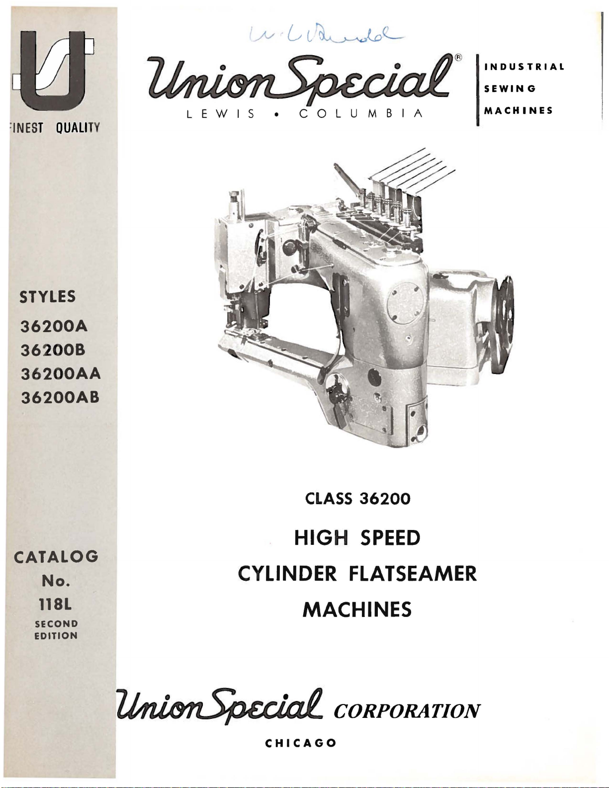
CLASS
HIGH
CYLINDER
MACHINES
36200
SPEED
FLATSEAMER
CHICAGO
TABLE
CATALOG
GENERAL
GENERAL
INSTRUCTIONS
EXPLODED
SALES
INFORMATION
Introduction-------------------------------------------------------------------------------------------Table
of
ldentliicationof~achines--------------------------------------------------------------------------------
Application
Description
Needles------------------------------------------------------------------------------------------------
Ordering
ThreadingandOiling-----------------------------------------------------------------------------------Diagram
Machine
Installationof~achine
Mounting
MachineSpeed-·----------------------------------------------------------------------------------------
SetiingUpThreadStand
Threading
Needle
Needle
Alignment
Timing
LooperAdjustment-------------------------------------------------------------------------------------FeedAdjustments---------------------------------------------------------------------------------------
Adjustment
Needle
LooperThreadAdjustment------------------------------------------------------------------------------Cover
Adjustment
Sewing
Drive
Main
Needle
Foot
Detachable
Dliferential
Feed
Looper
Dliferential
Presser
Presser
Thread
Contents---------------------------------------------------------------------------------------
of
Catalog-----------------------------------------------------------------------------------
of
~chine----------------------------------------------------------------------------------
Repair
Parts
Illustrations
Identifying
Use
Terms---------------------------------------------------------------------------------------------
SEWING
Preferred
Sequence
Unlocking
Replacing
to
and
of
Instructions
Feed
Rear
StuchLength--------------------------------------------------------------------------------------Differential
Presser
Thread
Thread
Plastic
VIEWS
Unit,
Reference
Frame,
Reference
Lever,
Reference
LUter
Reference
Reference
Reference
Drive
Reference
Rocker
Reference
Reference
Reference
Reference
Stand
Reference
Parts------------------------------------------------------------------------------------
Genuine
INFORMATION
for
Threading
Adjuster's
the
~achine
the
~achine
Threads----------------------------------------------------------------------------------
of
the
the
FOR
Looper
Needle
of
Needles
Needles
Height---------------------------------------------------------------------------------------Needle
Foot
of
Trimming
Adjustments------------------------------------------------------------------------------
Adjustment--------------------------------------------------------------------------------
of
Tension
With
AND
Belt
Number,
Wscellaneous
Number,
~ain
Number,
and
Tension
Number,
Head,
Number,
Feed
Number,
Assembly,
Number,
Shaft,
Number,
Feed
Number,
Bar
and
Number,
Foot
Shoes
Number,
and
Number,
----------------------------------------------------------------------------------
(explanation)---------------------------------------------------------------------------Needles
Threading-------------------------------------------------------------------------------
SEWING
Setting---------------------------------------------------------------------------------
for
Guard
Control---------------------------------------------------------------------------------
Adjustment----------------------------------------------------------------------------
Guard
Covers,
Bar,
Control,
Presser
Accessories----------------------------------------------------------------------------
and
Repair
Parts----------------------------------------------------------------
and
Oiling
Information
----------------------------------------------------------------------------------
-----------------------------------------------------------------------------------
---------------------------------------------------------------------------------
----------------------------------------------------------------------------------
Stitch--------------------------------------------------------------------------------Needle--------------------------------------------------------------------------------
ADJUSTMENTS
Bar----------------------------------------------------------------------------------
to
Throat
in
Relation
Using
Synchronizing
Adjustment-----------------------------------------------------------------------
Knives--------------------------------------------------------------------------
Release---------------------------------------------------------------------------
Nylon
Thread
DESCRIPTION
and
Part
Part
Shaft,
Part
Parts----------------------------------------------------------------------------
Part
Needle
Part
~ain
Part
Feed
Part
Looper
Part
Cylinder
Part
Feet---------------------------------------------------------------------------
Part
for
36200
Part
Part
------------------------------------------------------------------------
--------------------------------------------------------------------------
Plate
to
~ounting
Number
Covers,
Number
Crankshaft
Number
Number
Number
Feed
Number
Rocker,
Number
Drive
Number
Number
Number
~achines
Number
Number
---------------------------------------------------------------------
Looper-------------------------------------------------------------------
Gau
ge
and
Wuhout
OF
Stud-----------------------------------------------------------------
and
Bushings
and
and
and
and
Bar
and
and
Bar
and
and
Looper
and
and
and
Covers
and
and
and
and
the
PARTS
Description-----------------------------------------------------Description------------------------------------------------------
~iscellaneous
Description-----------------------------------------------------Description------------------------------------------------------
Needle
Description------------------------------------------------------
Feed
Description------------------------------------------------------
Avoid
Description------------------------------------------------------
Knlie
Drive
Description------------------------------------------------------
and
Description-----------------------------------------------------Description------------------------------------------------------
------------------------------------------------------------------Description------------------------------------------------------
Description------------------------------------------------------
OF
CONTENTS
NO.
118 L
No.
21227
CG
-----------------------------------------------
36211
Retainer--------------------------------------------
and
Take-up-------------------------------------------------
Oiling
---------------------------------------------
Bar
Head-------------------------------------------------
Lilt
Eccentric
Link
Parts
Bushings
Assembly-------------------------------------
Ball
Joints------------------------------------------
--------------------------------------------------
------------------------------------------7--------
Page
..1!2:....
2
3
4
4
4
4
5
5
5
6
6
6
7
8
9
9
9
9
9
9
9
10
10
11
11
11
12
12
13
13
14
14
14
14
14
15
16
16
16
16
17
18
19
20
21
22
23
24
25
26
27
28
29
30
31
32
33
34
35
36
37
38
39
40
41
NUMERICAL
UNION
Domestic
INDEX
SPECIAL
and
OF
SALES
Foreign
PARTS------------------------
OFFICES
Sales
Offices----------------------------------------------------------------
.
..
--------------------------------------------------
3
Back
42-43
Cover
IDENTIFICATION
OF
MACHINES
Each
the
machine.
numbers
Example:
only
minor
Style
herein.
References
operator's
is
Cylinder
Threads,
System,
Space
36 200 A
number.
This
It
clockwise.
and
in
and
shorts,
material,
607-FSa-1.
Union
catalog
Flatseamer,
Front
For
Special
Style
have
"Style
can
Manually
one
36200
changes
Example:
applies
also
to
direction,
position
FilterTypeOil
of
Needle 8 Inches.
simultaneously
and
where
carries
numbers
or
more
A".
are
made
be
applied
while
High
Operated
all
similar
seaming
a
Style
are
classified
letters
Special
in a standard
"Style
APPLICATION
specifically
with
such
as
seated
DESCRIPTION
Speed,
Differential
Return
trimming
and
Style
36200
discretion
right,
at
the
Medium
Pump,
knitted
closing
number
suffixed,
AZ".
to
left,
machine.
and
garments
which
as
standard
numbers
machine, a "Z"
OF
CATALOG
the
Standard
to
some
front,
OF
MACHINE
Throw,
Feed,
VisualSight
flat
seaming
elastic
is
stamped
and
but
never
contain
styles
Special
back,
Operating
Four
Automatic
Oil
infants'
made
is
necessary.
in'the
special.
contain
the
is
suffixed
of
machines
machines
etc.,
Needles,
ActionandSupply
of
are
direction
Enclosed
panties,
light
Seam
the
letter
given
One
to
medium
name
Standard
to
in
of
men's
Specification
plate
letter
"Z".
the
this
Looper,
Type
When
standard
as
listed
Class.
from
handwheel
Oiling
Gauges,
briefs
weight
on
Style
"Z".
the
Six
36200 B For
sleepers
weight
Specification
36200
36200
number
The
blade
Collectively,
Thread
formation.
machine.
by a reputation
of a century.
round
diametershank,
AA
AB
Each
Selection
For
StandardneedleforStyles
Union
denotes
size
measured
should
best
shank,
simultaneously
or
material,
Same
Same
Special
the
number,
the
of
proper
pass
results,
They
are
for
round
chromiumplated,
similar
607-FSa-1.
as
as
stamped
in
thousandths
type
packaged
producing
where
Style
Style
needle
kind
number
needle
freely
use
point,
garments
of
seaming
36200
36200
shank,
on
size
through
only
under
36200
extra
trimming
and
A,
B,
NEEDLES
has
both a type
point,
the
needle
of
an
and
size
should
the
genuine
our
highest
A,
short,
and
and
all
and
closing
except
except
length,
shank,
inch
number
be
determined
needle
Union
brand
quality
B,
AA
double
is
available
flatseaming
knitted
number
midway
eye
Special
name,
needles
and
fabrics
elastic
prepared
prepared
groove,
denotes
between
represent
in
needles
~
AB
is
groove,
in
sizes
underwear,
made
is
for
for
and a size
finish,
the
largest
by
the
size
order
for
to
more
Type
struck
025, 027,
in
118
children's
of
light
not
necessary.
Pedestal
Pedestal
number.
and
the
shank
the
complete
of
produce a good
the
operation
•
which
than
GAS-029.
groove, • 060
to
Installation.
Installation.
other
diameter
and
the
thread
is
three-quarters
029, 032,
knit
medium
Seam
The
type
details.
of
the
the
eye.
symbol.
used.
stitch
of
this
backed
It
has
inch
036.
a
To
have
needle,
A
complete
or
needle
the
order
type
orders
and
would
promptly
size
number
read:
and
"1000
accurately
should
Needles,
be
forwarded.
Type
filled,
4
118
an
Use
GAS,
empty
description
Size
package, a sample
on
label.
029".
ILLUSTRATIONS
This
catalog
views
seen
will
the
of
various
in
their
actual
be
found a listing
number
of
pieces
has
been
sections
position
required
ORDERING
arranged
ofthe
in
the
of
the
parts
REPAIR
to
simplify
mechanism
machine.
with
in
the
particular
On
their
PARTS
ordering
are
shown
the
parts
view
repair
sothatthe
page
opposite
numbers,
being
parts.
parts
the
description
shown.
Exploded
maybe
illustration
and
Numbers
dicate
never
second
indicated
sub-assembly.
the
position
be
used
column.
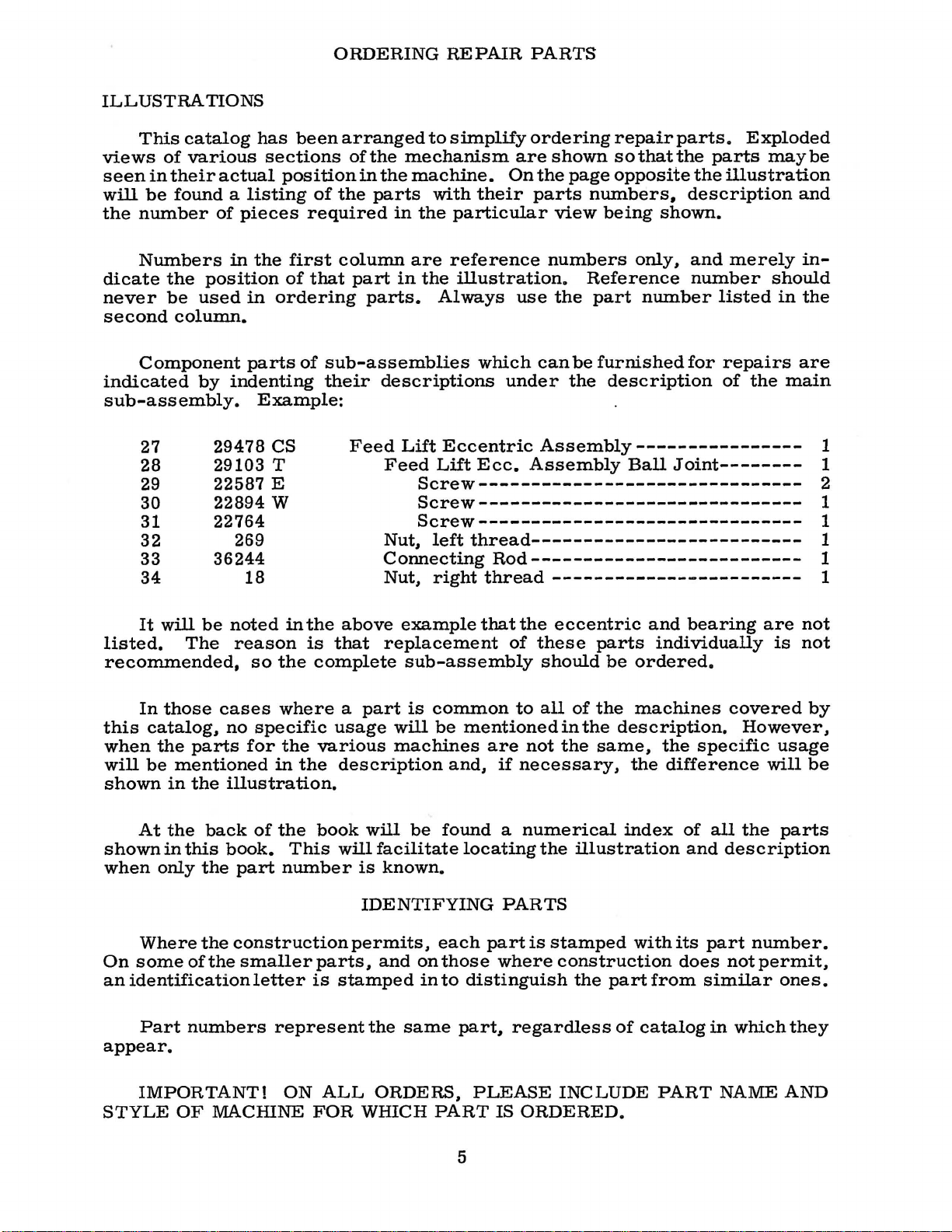
Component
by
27
28
29
30
31
29478
29103 T
22587
22894 w
22764
32
33
36244
34
It
will
be
listed.
recommended,
this
when
will
shown
The
In
those
catalog,
the
parts
be
mentioned
in
the
in
the
first
of
in
ordering
parts
indenting
of
Example:
cs
E
269
18
noted
reason
cases
no
illustration.
in
so
the
where a part
specific
for
the
in
the
column
that
part
in
parts.
sub-assemblies
their
the
is
complete
various
descriptions
Feed
above
that
usage
description
Lift
Feed
Nut,
Connecting
Nut,
example
replacement
sub-assembly
will
machines
are
reference
the
illustration.
Always
Eccentric
Lift
which
Ecc.
numbers
Reference
use
the
can
be
under
the
Assembly----------------
Assembly
only,
part
number
furnished
description
Ball
and
merely
number
listed
for
repairs
of
the
Joint--------
Screw------------------------------Screw------------------------------Screw-------------------------------
left
thread--------------------------
Rod--------------------------
right
is
common
be
thread
that
of
mentioned
are
and,
if
------------------------
the
eccentric
these
should
to
all
not
necessary,
of
in
the
parts
be
ordered.
the
machines
the
description.
same,
the
and
bearing
individually
covered
the
specific
difference
are
However,
will
in-
should
in
the
are
main
not
is
not
by
usage
be
1
1
2
1
1
1
1
1
At
the
shown
when
On
an
appear.
STYLE
in
only
Where
some
identification
Part
IMPORTANT!
OF
back
this
the
the
of
numbers
of
the
book.
part
number
construction
the
smaller
letter
represent
ON
MACHINE
book
This
parts,
is
FOR
will
will
facilitate
is
known.
IDENTIFYING
permits,
and
stamped
the
same
ALL
ORDERS,
WHICH
be
found a numerical
locating
PARTS
each
on
in
PART
part
those
to
where
distinguish
part,
PLEASE
IS
5
is
regardless
ORDERED.
the
stamped
construction
INCLUDE
index
illustration
with
the
part
from
of
catalog
PART
of
and
its
does
similar
all
the
description
part
number.
not
permit,
in
which
NAME
parts
ones.
they
AND
USE
GENUINE
NEEDLES
AND
REPAIR
PARTS
Success
Union
ation.
to
Maximum
repair
your
ments
are
insurance.
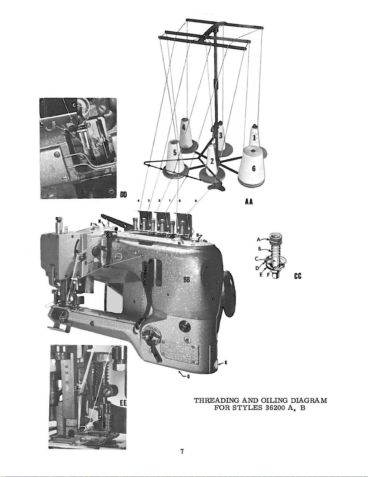
VIEWS AA
to
spring
VIEW
Disc.
and
VIEW
Special
its
the
most
Genuine
parts
guarantee
Prices
are
insured
Thread
3,
2.
1.
at
CC:
Close-up
upper;
Pass
'E".
DD:
Close-up
in
the
Needles
subsidiaries
approved
efficiency
needles
are
of
are
strictly
forwarded
unless
AND
5.
needle
threads
BB:
as
indica
and 6 in
thread
of
tension
E.
Disc.
of
looper
operation
and
and
scientific
and
durability
are
packaged
stamped
the
highest
net
at
the
otherwise
THREADING
ted
in
order
frame
post
lower;
thru
slots
thread
of
these
Repair
authorized
with
cash
buyer's
illustration
and
''F"
Parts
principles.
the
quality
risk
directed.
AND
passing
eyelet
assembly.
F.
Post
in
and
cover
machines
distributors.
are
assured.
with
labels
Union
in
materials
TERMS
and
subject
f.
A
OILING
on
opposite
needle
''G".
Slot.
tension
as
furnished
and
Special
o.
b.
charge
A.
post
thread
can
be
secured
by
the
They
are
made
marked
trade
to
shipping
INFORMATION
page.
threads
Tension
''C'~
take-ups.
~
mark.
and
workmanship.
change
point.
is
made
starting
UNDER
Nut;
and
between
without
Union
are
with
Parcel
to
B.
only
designed
utmost
Each
cover
with
the
Spring;
with
Special
trade
notice.
Post
the
postage
#4.
progressing
stitch
c.
tension
genuine
Corpor-
according
precision.
•
Genuine
mark
All
ship-
shipments
and
unlocking
Post;
discs
D.
''D"
is
VIEW
Close-up
Referring
"J".
Oil
mineral
checked
frame
tain
oil
Automatic
of
oil
can
top
cover.
time.
holes
flow
and
screw
with
holder
bearings
with
while
Oil
back
the
Occasionally.
EE:
capacity
oil.
Saybolt
at
the
under
priming
at
shank
the
level
is
hole
between
be
observed
When
recommended
machine
drained
of
drive
''Q"
be
in
of
the
of
needle
to
illustration
of
two
foot
lubrication
installing a new
may
pulley.
sure
the
it
No.
presser
thread
Class
viscosity
sight
lifter
red
thru
be
necessary.
is
running.
from
the
bottom
is
necessary
36273
foot
gauges
oil
machine
hole
A.
sequence.
on
36200
of
lever
lines
is
featured
windows
and
Belt
in
of
the
guide
lifting
opposite
is
two
90
to
'K"
and
and
at
of
these
''M"
machine
To
replace
pump
at
two
cover
the
filter
cylinder.
to
collar
mechanism
OILING
page.
ounces
125
"L".
the
front
gauges.
with a continuously
and
or
do
so.
screws
is
inoperative.
places.
must
oil
the
machine
in
each
seconds
located
of
''N"
in
starting
remove
BEFORE
first
box.
No.
that
linkage
36273 K and
and
at
the
crank
one
"Q"
and
be
removed.
the
of
thread
100
on
cylinder.
is
filled
oilc5eservoir.
Fahrenheit.
the
driven
chamber
that
the
two
operating.
''R".
screw
the
tension
at
right
respectively,.
rotary
has
been
plug
''R"
When
goes
presser
the
various
the
caps
Use a straight
The
side
is
release.
of
pump.
cover
idle
screws
If
oil
located
replacing
into.
foot.
the
and
for
does
the
links
''H"
level
main
Main-
front
some
''P".
below
lines
knife
and
is
Flow
fill
not
the
up
and
6
AA
cc
THREADING
FOR
7
AND
STYLES
OILING
36200
DIAGRAM
A,
B

INSTALLATION
OF
MACHINE
Where a power
on a Union
the
use
table
(#35895
Corrugated
Add
left
rear
(#22652
before
Pulley.
sufficiently
finger
milled
milled
Screws
Lever
(#421
operation.
of 2 1/4
of
board
It
is
more
R)
three
and
front
Stud
Correct
F-20)
tightening
Tighten
pressure.
flat
groove.
(#25
Refer
(#36280
D-38)
The
speed
inches,
Special
Rubber
may
be
convenient
into
the
Isolator
Felt
Sleeves
Studs,
so
that
Screws
and
Belt
tight
if
as a more
Do
S).
to
Page
F).
or
Lifter
of
Since
the
stand
table
Feet
(#21371
prepared
base
(#660-275)
(#660-161)
tighten
Drive
for
are
packedin
securely.
by
while
Secure
favorable
not
tighten
25;
assemble
The
Rod.
the
Machine
the
Handwheel
size
or
line-shaft
board
Unit
assembling
to
to
set
of
the
first
has
Place
turning
one
side
the
flange
hole
of
the
closes-t:
in
JT),
obtain
Drive
in
small
againstthread
Lifter
is
Pulley,
Motor
installation
order
especially
isolation
up
the
Unit
this
on
each
Nut
with
about
1/32
Machine
parts
short
flange
remains
position
position,
Lever
to
4200
R.
Pulley
to
obtain
on
as
Machine
and
order
to
Stud
and
fingers
less
MOUNTING
to
Drive
box.
Belt
(#21261
of
Adjustable
straight
by
tightening
move
on
(#36280
the
Fulcrum
MACHINE
P.M.,
which
is
may
is
desired,
the
benefits
wooden
shown
Drive
tighten.
each
Stud
press
only.
gap
at
THE
Unit
Freedom
the
the
Set
Pulley
F)
which
grooved
be
approximated
floors.
on
Unit
Add
and
into
Lock
rear.
MACHINE
are
M-210)
Pulley
opposite
the
Screw
Core.
and
Screw
SPEED
may
for
it
is
of
isolated
Planograph
first
and add
one
steel
set
Unit
holes.
into
position
Lock
Allen
of
screw
first
clockwise
side
Set
Screw.
to
this
Add
Belt
the
Link
will
provide
be
modified,
a #1
or
recommended
moWlting,
However,
with
Machine
Washer
on
table,
Assemble
with
into
position
Head
Cap
bodyin
over
may
(#36280
3L
by
the
hole
Adjustable
to
increase
be
deflected
If
the
hole.
Guard
more
dependent
section
following
that
which
if
such a board
template
later.
(#21371
Studs
balance
second
with
Screws
permits
Pulley
the
open
Make
G).
sure
(#36295
Two
lift.
Vee
formula:
upon
Belt,
the
machine
is
further
PL443.
Insert
UE)
extending
of
parts
Nut.
Tighten first
second
3/8-
Machine
and
pitch
inwardly
screw
Screw
J)
with
holes
Attach
the
has a pitch
is
not
the
and
one
through
per
Nut.
16 x 1
then
diameter.
1/4
hole
lines
seats
two
Fillister
are
provided
the
conditions
be
installed
improved
available,
three
Neoprene
PL443.
1/4
inch
to
belevelled
on
Machine
Belt
inch
by
up
on
Lifter
diameter
Studs
holes.
On
Nut
long
light
with
flat
Head
in
the
Chain
of
the
by
a
on
is
a
of
For
diameter.
variable
tachometer
It
convenient
machine)
to
PREFERRED
travel
may
for
adequate
more
on
Union
pitch
is
unnecessary
Fasten
Brackets
prevent
The
Machine
indica!es
be
used m the
the
Looper
strength.
It
is
more
uniform
operation
for
Special
Due
to
variations
pulley,
to
determine
to
Thread
to
threading.
for
interference
and
Stand
bring
into
attaching
THREADS
will
right
Looper
since
economical
stitch,
material.
Pitch
Electro
an
remove
direct
between
operate
twist. A 70-3
there
thereby
Drive
in
absolute
the
actual
the
to
table
line
Thread
satisfactorily
as
well
is
insufficient
over a period
reducing
Dia.
Pulleys,
actual
value
speed.
Belt
Guard
board
the
Lead-in
Thread
or
as
the
of
Motor
pitch
SETTING
with
threads
Cones
THREADING
80-3
cover
oftime
the
Pulley
add
diameters,
will
not
The
(#36295
three
which
Guides
and
with
cord
thread.
yarn
to
to
possibility
=
1/4
inch
be
obtained
tachometer
J),
since a hole
UP
THREAD
(#SC303)
lead
should
either
the
is
used
resist
use
be
Lead-in
THE
left
The
abrasion
the
of
down-time.
2. 25 x
motor
into
located
in
better
R.
R.
to
the
and
should
STAND
Flat
the
Guides.
MACHINE
or
right
the
needles
25/1
to
grades
P.M.
of
Machine
P.
M.
of
Motor
calculated
speeds,
therefore,
be
has
Head
Eyelets
as
shown
twist,
28/1
of
wearing,
However a selection
tension
applied
been
Wood
of
on
although
and
yarns
ofthread
pitch
it
to
provided
Screws
Machine.
PL437
30/2
are
although
'
diameter
of
the
becomes
the
end
for
(#12X1)
(also
the
to
50/2
definitely
and
yarn
to
Jack
necessary
of
the
this
See
PL425
packed
direction
soft
NOT
the
seam
since
of
obtain
at a location
thread
the
Belt
and
MACHINE
purpose.
mercerized
they
to
(packed
with
machine)
of
the
recommended
has
more
produce
will
outside
size
use
Shaft.
most
with
Looper
yarn
than
depend
of
a
a
SEQUENCE
.Mac~ne
pos1tiorung.
Foot.
Place
Eyelets
Cones
as
OF
THREADING
has
been
Sample
on
shown
on
sewed
of
fabr1c
Thread
PL425.
.off
should
Stand
Unwrap
atfactory
be
Seats
and
closely
and
pull
threads
PL425
observed
thread
from
is
packed
from
Presser
as
cones
to
with
each
introduction
on
Bar.
stand
cut
9
machine
of
thru
off
and
as
guidetothreading
fabric
Lead-in
tie
between
to
threads
Guides
toes
to
Tension
from
and
of
the
cone
Presser
Post
Cones.
Turn
Pull
thread
With
and
the
Handwheel
threads
above
stitch
knots
Needle
formation.
clockwise.
from
Bar
above
and
raised,
cut
needle
off
lift
Stop
with
eyes
close
Presser
Needle
thru
to
Needle
Foot
Bar
system
and
at
Eyes,
remove
top
of
until
knots
DO NOT
the factory
its stroke,
pass thru Needl
RE-THREAD
sample,
e B
ar
Head Eye
NEEDL
Observe method
ES
let.
AT
THIS
of
entering Foot
Cut
TIME.
off
Looper
tore-thread
THREAD
observe
Check
tension;
section
UNLOCKING
Turn
then,
downward app
mark
threads
With
the
needles,
If
free
ends
formed,
REPLACING
formation
Tension
when Foot
on
"Adjustment
the
turn
the
on
the Head
to
be
threads
the
stitch
of
This
and
Cover
the
NEEDLES
THE
Handwheel
Hand
roximately
pulled
Without a chain,
all
is
THE
Thread
Looper
of
stitch.
Rel
ea se when
is ra·
STITCH
wheel
Cover. Lift the Presser Foot
from
unlocked,
is
unlocked
the
threads firmly
termed"
NEEDLE
and
and
sed,
of
Tension
in
in the
1/8
under
start
can
now
Cover
the
it
Thread
place
one
Foot
all
threads
Release".
operating or
reverse
inch
to
where the
the Foot
must
be
material must
and
it
is
behind
ing
the
be
tied
Carrier.
ply
of
is
raised bef
must
direction
freely.
understood
desired
the Foot bef
chain
" .
and
pulled
thru,
with
material
be
clockwise direction
until
top
be
under
to
start
Machine
under Foot.
ore
sewing with
completely free,
the
the
high as
that
the
the
ore
Needle Bar
Needle
possible,
it
is
only
Foot
machine
starting
will
then
of
as
Needle
until
Lever
to
when
the
chain
Bar
Manually
power.
If
the
the Needle
has
reached its hig
Thread
thus
introduce
starting to
without
machine,
indefinitely.
at highest
turn
When
se
conditions
Eyelet
opening
work
sew.
material,
unt
point.
clockwise
Foot
is down,
Bar
is
hest
is
in
the
Tensions
under
it
is
il a small
It
is
several times
all
are
not
in its
lowest
position and
line
with
which
the
Foot
imperative
amount
unnecessary
threads
met, ref
position,
moved
the
top
of
allow
from
behind
to
hold
of
cha
and
have
er
the
the
the
in
to
is
Union
To
remove Nee
Needle.
on
the
machine
should
TO
the
machine
Foot,
remove
(#36270)
left
withdraw
to
Special
assists
flat
matically
to
Looper.
remove
seated
If
adjustments
F
amiliarity with
but
care
NEEDLE
If
Presser
To
Knife
Cover,
partially
of
Needle
The
(Pa
Needles
operator
Retainer,
dle,
To
ge 27).
for
in
correctly
to
the
bring Needle
replace
Needle,
INSTRUCTIONS
has
been
be
made
the
machine
be
taken
LOOPER SETTING
is ass
Throat Plate
Presser Foot
and
(#36289 A, Page 27)
Looper
release knife
Pre
setting,
disassembled,
in
the
following sequenc
will per
to
observe
embled
and
(#36220),
ss er
Bar (#36278),
the
FLA
TSEAMER
locating
right
of
the
Bar
to
make
re-adjusting
mit individual adj
that
the
prop
and
it
is
Main Feed Dog
pressure
and
desired
raise
Presser
Removal
are
the
fourth
maximum
certain
FOR
e,
which,
er
should
Needle Bar
by
unclamping Knife
Foot Brace (#36278
made
relative
Needle,
height,
that
SEWING
for
throu
ustments
relationship
to
proceed
be
to
of
Throat Plate
Shank
sew
removed,
maximum heig
with
two
flats
position
requires
break
is
inserted
of
Needles
no
thread
on
orienting
to
ADJUSTMENTS
ing
-off
is
gh
experience,
of
of
with
E),
an
adjustment
the
Guide
assembl
Needle
ht
(#36273 B ).
Release
and
Main
required,
and
front
of
Shank,
in
Needle
and
consequently has
at
eye,
loosen
full
depth
and
has
ed
is
to
Presser
and
proven generally
machine
maintained,
Looper
remove Retainer
Feed
setti
Remove Detachable
Bar
Dog
Bar
Screw
it
is sugg
to cor
ng,
Gui
will
This
design
Head
with
(#22738
that
Screw
est
ed
sat
rect malf
the
Upper
(#36211), Upper
de (#36278
permit
observation
respect
is
that
isf
actory.
unct
auto-
no
flat
H)
firmly
ion,
Knife,
Hea
B)
and
.
and
the
d
10
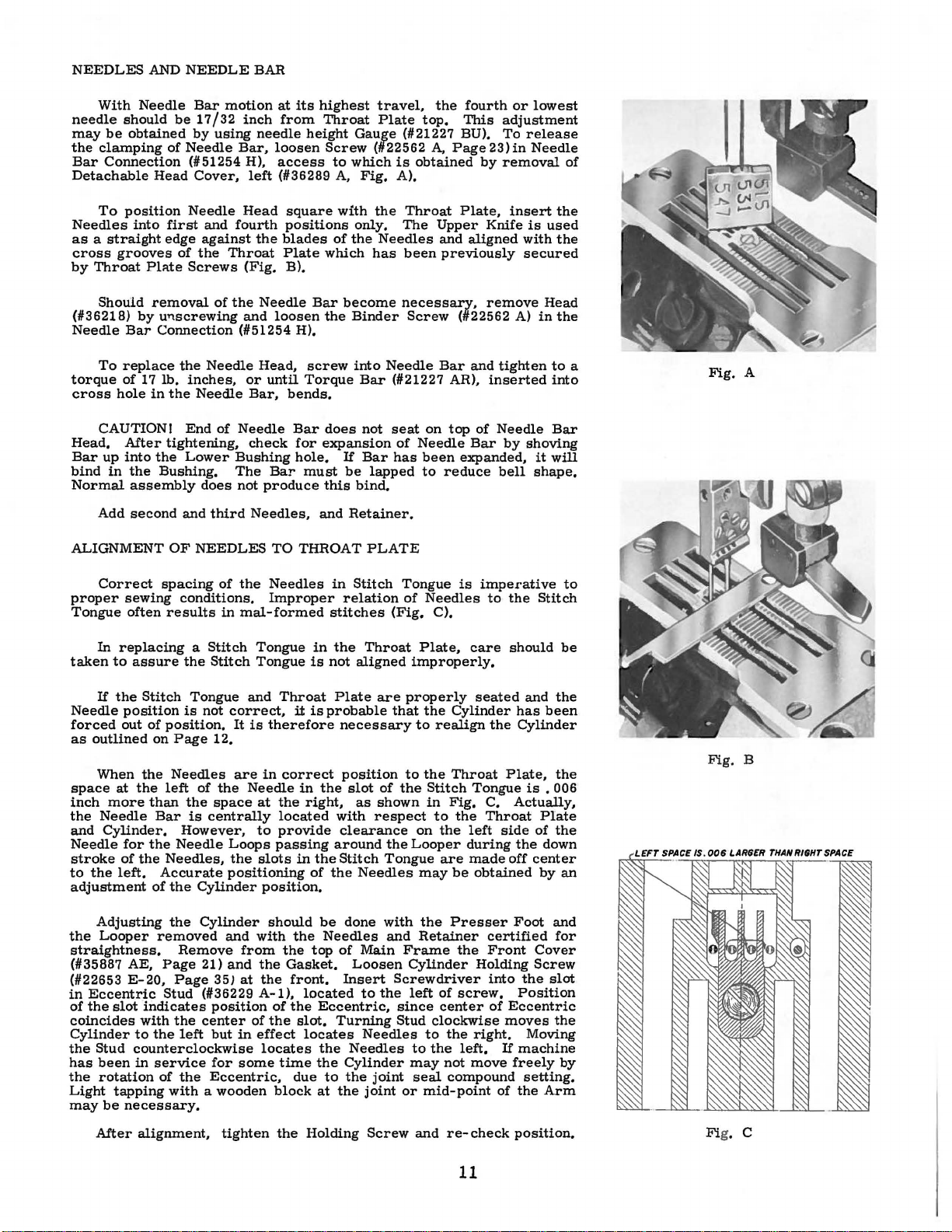
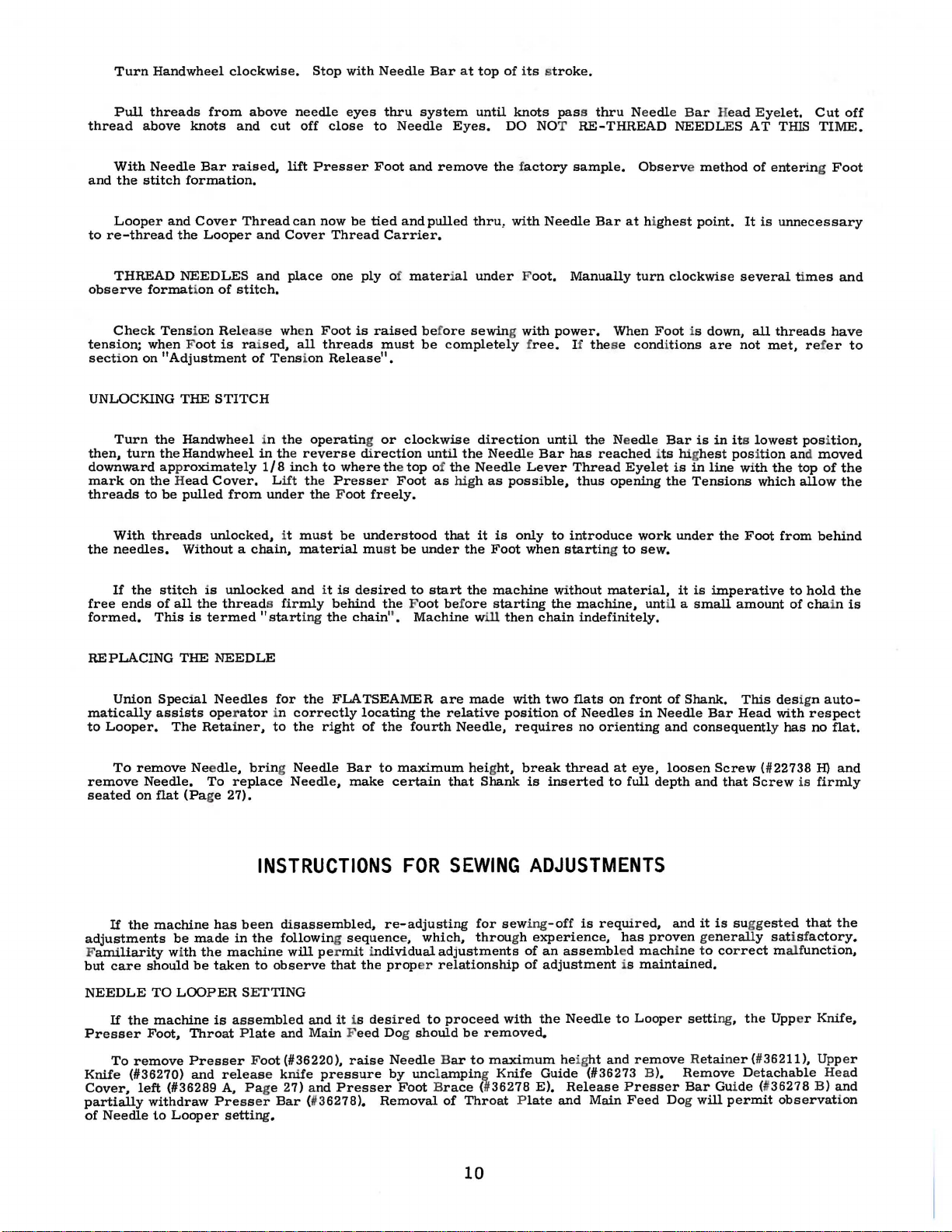
NEEDLES
With
needle
may
the
Bar
Detachable
Needles
as a straight
cross
by
Needle
should
be
obtained
clamping
Connection
To
position
into
grooves
Throat
Pl::tte
AND
be
of
Head
first
edge
NEEDLE
Bar
motion
17/3 2 inch
by
using
Needle
(#51254 H),
Cover,
Needle
and
fourth
against
of
the
Throat
Screws
BAR
needle
Bar,
left
Head
the
(Fig.
at
its
highest
from
Throat
height
loosen
access
(#36289 A,
Screw
square
positions
blades
Plate
which
B),
to
with
of
travel,
Plate
Gauge
(#22562
which
Fig,
the
only,
the
Needles
has
the
fourth
top,
(#21227 BU),
is
obtained
A),
Throat
The
been
This
A,
Page
Plate,
Upper
and
aligned
previously
or
adjustment
To
23)in
by
removal
insert
Knife
lowest
release
Needle
the
is
used
with
the
secured
of
Should
(#36218)
Needle
To
torque
cross
CAUTION!
Head,
Bar
up
bind
Normal
Add
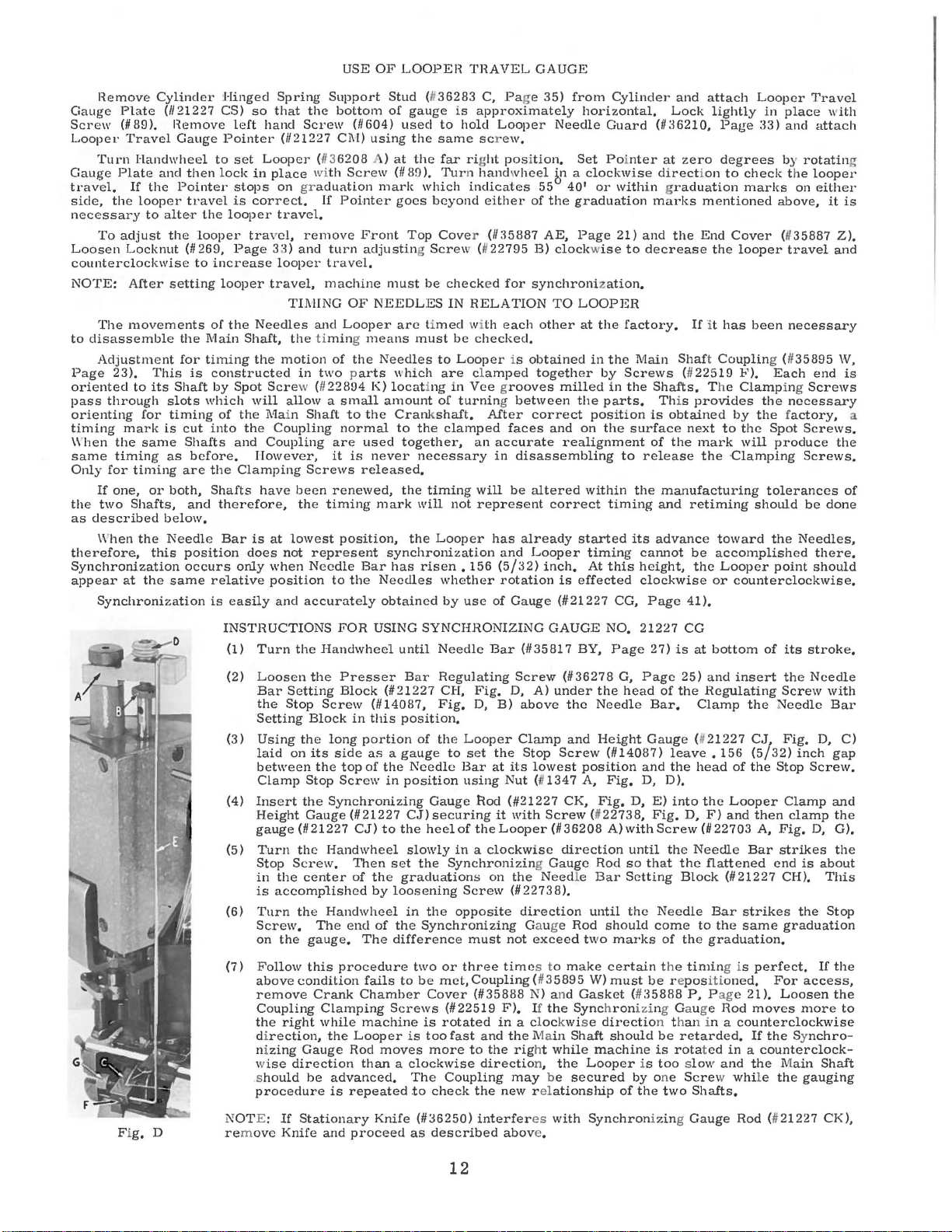
ALIGNMENT
Correct
proper
Tongue
In
taken
If
Needle
forced
as
outlined
When
space
inch
the
Needle
and
Cylinder.
Needle
stroke
to
the
adjustment
removal
by
Bar
replace
of
17
hole
in
After
into
in
the
assembly
second
sewing
often
replacing a Stitch
to
assure
the
Stitch
position
out
of
on
the
at
the
more
than
for
the
of
the
left,
of
U'1Screwing
Connection
lb,
the
tightening,
the
Bushing.
spacing
results
position.
left
Bar
Needles,
Accurate
of
the
Needle
inches,
Needle
End
of
Lower
does
and
third
OF
NEEDLES
of
conditions,
the
Stitch
Tongue
is
not
Page
12,
Needles
of
the
the
space
is
centrally
However,
Needle
the
Cylinder
the
Needle
and
loosen
(#51254 H),
Head,
or
until
Bar,
Needle
check
Bushing
The
Bar
not
produce
Needles,
TO
the
Needles
in
Improper
mal-formed
Tongue
Tongue
and
It
is
are
Needle
Throat
therefore
in
at
the
located
to
provide
passing
slots
position.
correct,
Loops
the
positioning
Bar
screw
Torque
bends,
Bar
for
hole,
must
and
THROAT
in
is
it
is
correct
in
the
right,
in
the
of
become
the
Binder
into
Bar
does
not
expansion
If
Bar
be
lapped
this
bind,
Retainer,
PLATE
in
Stitch
relation
stitches
the
Throat
not
aligned
Plate
probable
are
necessary
position
slot
as
shown
with
respect
clearance
around
Stitch
the
Needles
necessary,
Screw
Needle
of
the
Tongue
Bar
(#21227 AR),
seat
on
of
Needle
has
been
to
reduce
Tongue
of
Needles
(Fig,
C).
Plate,
improperly,
properly
that
the
to
realign
to
the
the
Stitch
in
to
on
the
Looper
are
may
remove
(#22562 A)
and
tighten
inserted
top
of
Needle
Bar
expanded,
bell
is
imperative
to
care
seated
Cylinder
the
Throat
Tongue
Fig,
C,
the
Throat
left
during
made
be
obtained
by
shoving
it
shape,
the
Stitch
should
and
has
Cylinder
Plate,
is
Actually,
side
of
the
off
center
Head
in
the
to
into
Bar
will
to
be
the
been
the
• 006
Plate
the
down
by
an
a
Fig.
Fig.
A
B
Adjusting
the
Looper
straightness,
(#35887 AE,
(#22653
in
Eccentric
of
the
slot
coincides
Cylinder
the
Stud
has
been
the
rotation
Light
tapping
may
be
After
the
Cylinder
removed
Remove
Page
E-20,
indicates
with
to
the
counterclockwise
in
service
necessary.
alignment,
21)
Page
Stud
of
35)
(#36229
position
the
center
left
but
for
the
Eccentric,
with a wooden
and
with
from
and
at
A-1),
of
in
effect
some
tighten
should
the
the
the
Gasket,
the
front.
of
the
the
locates
time
due
block
the
be
Needles
top
located
Eccentric,
slot,
locates
the
the
to
at
Holding
done
of
Main
Loosen
Insert
to
the
Turning
Needles
Needles
Cylinder
the
joint
the
joint
Screw
with
the
and
Retainer
Frame
Cylinder
Screwdriver
left
of
since
center
Stud
clockwise
to
to
the
may
not
seal
or
mid-point
and
Presser
certified
the
Front
Holding
into
screw.
of
the
right.
left,
If
move
compound
re-check
of
Foot
and
Cover
Screw
the
slot
Position
Eccentric
moves
Moving
machine
freely
setting.
the
Arm
position,
for
the
by
11
Fi
g. c
USE
OF
LOOPEH
THAVEL
GAUGE
Hemove
Gauge
Screw
Looper
Turn
Gauge
travel,
side,
necessary
To
Loosen
Plate
{1189
Travel
Handwheel
Plate
If
the
looper
to
adjust
Locknut
Cylinder
{1121227
).
and
the
alte
counterclockwise
NOTE:
to
After
The
movements
disassemble
Adjustment
Page
23).
oriented
pass
orienting
timing
\\'hen
same
Only
If
the
two
as
described
When
therefore,
to
through
for
mark
the
same
timing
for
timing
one,
Shafts,
the
This
its
is
or
below.
this
Synchronization
appear
at
the
Synchronization
He
move
Gauge
then
Pointer
travel
·r
the
looper
(11269,
to
setting
the
for
is
Shaft
slots
timing
cut
Shafts
as
before.
are
both,
and
Needle
position
occurs
same
Hinged
CS)
left
Pointer
to
set
lock
stops
is
the
looper
travel,
Page
increase
looper
of
the
Main
Shaft,
timing
constructed
by
Spot
which
of
the
into
the
and
the
Clamping
Shafts
therefore,
Bar
does
only
relative
is
easily
Spring
so
that
the
hand
Screw
(1121227
Looper
in
(
place with
on graduation
correct,
travel,
remove
3;
i)
and
looper
travel,
TIJ\IING
Needles
and
the timing means
the
motion
in
Scre
will
i\1ain
two parts
w (
11
allow a small
Shaft
Coupling
Coupling
However,
Screws
have
been
the
is
at
lowest
not
represent
when
Needle
position
and
accurately
Support
bottom
{11604)
Cl\l)
using
113
6208
Screw
If
Pointer
Front
turn
adjusting Screw
travel.
machine
OF
NEEDLES
Looper
of
the
22894
K)
to
the
normal
are
used
it
is
never
released.
renewed,
timing
position,
Bar
to
the
Stud
{#
gauge
used
the
at
the
(118f.J
goes
Top
36283
is
to
same scr
far rig
).
Turn hand
which
beyond
Cove
be
checked
IN
approximately
hold
indicates
r (1135887
(#
RELATION
of
)
mark
must
are limed with each
must
be
checked,
Needles
amount
which
locating
to
Looper
are
clamped
in
Vee grooves
of
turning between
Crankshaft,
to
the
clamped
together,
an
necessary
the
mark
timing
will
the
not
Looper
will
represent
synchronization
has
risen.
Needles
obtained
156
whether
by
use
C, Page
Looper
ew,
ht
position,
wheel
either
22795
for
is
After
faces
accurate
in
disassembling
be
has
already
and
(5/32)
rotation
of
Gauge
35)
from
Cylinder
horizontal,
Needle
Guard
Set Poi
f:p
a
clockwise
1
55
40
or
of
the
AE,
B)
clockwise
within graduation
graduation
Page
21)
to
synchronization,
TO
LOOPER
other
at
the
factory.
obtained
together
correct
milled
and
in
by
the
parts,
position
on
the
the
Screws
in
the
realignment
to
altered
correct
within
timing
started
Looper
inch,
is
(#21227
timing
At
this
effected
CG,
Lock
{113
nter
at
direction
marks
and
the
decrease
Main
Shafts.
Th
is
obtained
surface
of
the
release
the
manufacturing
and
its
advance
cannot
height,
clockwise
Page
and
attach
lightly
6210,
Page
zero
degrees
to
check
marks
mentioned
End
Cover
the
looper
If
it
has
Shaft Couplin
(1122519
is
Th e
provides
F).
Clamp
by
next
to
the
mark
will
the
Clamping
retiming
toward
be
accomplished
the
Looper
or
counterclockwise.
41),
Looper
in
33)
place
and
by
rotatin
the
Travel
looper
on
above,
(#
35887
travel
been
necessary
g (
11
35895
Each
end
ing
the
Screws
necessary
the factory,
Spot
Screws.
produce
Screws.
tolerances
should
the
point
be
Needles,
should
with
attach
either
it
Z).
and
W,
the
done
there,
g
is
is
a
of
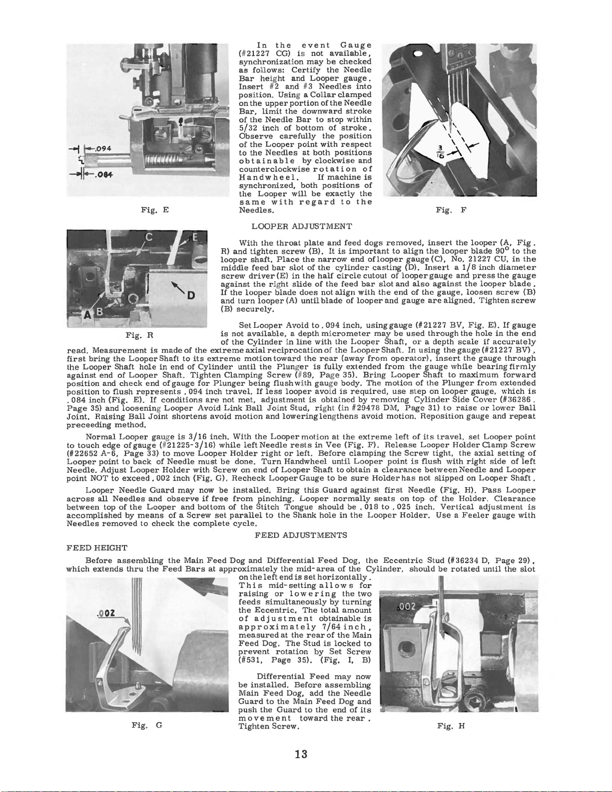
INSTRUCTIONS
(1)
Turn
the
(2)
(3)
(4)
(5)
(6)
(7)
Loosen
Bar
the
Setting
Using
laid
between
Clamp
Insert
Height
gauge
Turn
Stop
in
is
Turn
Screw.
on
Follow
above
remove
the
Setting
Stop
Block
the
on
its
the
Stop
the
Gauge
(1121227
the
Screw.
the
center
accomplished
the
The
the
gauge.
this
condition
Crank
Coupling
the
right
di
rection,
ni
zing
Gauge
w
ise
direction
s
hould
be
procedure
FOR
USING SYNCI-IHONIZING
Handwheel
Presser
Block
in
this
portion
as a gauge
top
of
Screw
(#21227
(1114087,
the
in
Screw
long
side
Synchronizing
(1121227
CJ)
to
Handwheel
Then
of
the
by
Handwheel
end
of
The
procedure
fails
Chamber
Clamping
while
machine
the
Looper
Rod
moves
than a clockwise
advanced,
is
repeated
until
Needle
Bar
Regulating
Fig,
position,
of
the
Needle
position
Gauge
CJ)
securing
the
heel
slowly
set
the
graduations
loosening
in
the
the
Synchronizing
difference
two
to
be
Cover
Screws
is
is
too
more
The
to
check
GAUGE
Bar
(#35817
Screw
CH,
Fig.
D,
A)
above
Clamp
Stop
its
lowest
with
under
Screw
(111347
Screw
(1136208 A)
direction
D,
B)
Looper
to
set
the
Bar
at
using
Nut
Rod
(#21227
it
of
the
Looper
in a clockwise
Synchronizing Gauge
on
the
Screw
opposite
Need
(112273
direction
8),
Gauge
must
not
exceed
or
three
time
met,
Coupling
(1135888 N) and
(#22519
rotated
fast
and
to
the
directio
Coupling
the
s to
(1135895
F),
If
the
in a clockwi
the Main
rig
ht
while
n,
the
may
be
new rel
ationship
BY,
(#36278
the
the
Needle
and
Height
position
A,
CK,
Fig.
(1122738,
Rod
le
Bar
until
Rod
two
make
W)
Gasket
Synchron
s e
Shaft
machine
Looper
secured
NO.
21227
Page
G,
Page
head
(#14087)
and
Fig.
D,
D,
with
until
so
Setting
the
should
marks
certain
must
(#
izi
directio
should
is
by
of
the
CG
27)
is
25)
of
the
Bar.
Gauge
leave.
the
D).
E)
into
Fig.
D,
Screw
the
that
the
Block
Needle
come
of
the
t he
be
r e
pos
:l5888
ng Ga ug e
n t h
an
be
retarded.
is
rotated
too slow
one
Screw while
two
at
bottom
and
insert
Regulating
Clamp
(1121227
head
156
of
the
Looper
F)
and
(#22703
the
Needle
flattened
(1121227 CH).
Bar
strikes
to
the
same
graduation,
timin
g is
iti
oned,
P, Pag
e
21).
Rod
in a
counterclockwise
in a counterclock-
and
Shafts.
of
its
the
Screw
Needle
CJ/
Fig.
(5
32)
the
inch
Stop
Clamp
then
clamp
A,
Fig.
Bar
strikes
end
the
graduation
perfect,
For
Loosen
moves
If
the Synchro-
the
Main
the
stroke.
Needle
with
Bar
0,
gap
Screw.
and
the
D,
G).
the
is
about
This
Stop
If
the
access,
the
more
Shaft
gauging
C)
to
Fi
g,
D
NOTE:
remove
If
Stationary
Knife
and
Knife
proceed
(1136250)
as
described
interfer
abov
es
e.
with
12
Synchronizing Gauge
Rod
(#
21227
CK),
read.
Measurement
first
bring
the
Looper
against
position
position
.
Page
Joint.
preceeding
to
(#22652
Looper
Needle.
point
across
between
accomplished
Needles
FEED
which
084
touch
end
and
to
inch
35)
and
Raising
Normal
edge
A-6,
point
Adjust
NOT
Looper
all
top
removed
HEIGHT
Before
extends
(Fig.
Fig.
E
Fig.
R
is
the
Looper
Shaft
of
Looper
check
flush
loosening Looper
Ball
method.
Looper
ofgauge (#21225-3/16)
Page
to
Looper
to
exceed.
Needle
Needles
of
the
by
assembling
thru
made
Shaft
hole
in
end
Shaft.
end
of
If
conditions
Joint
gau
ge
33)
to
of
Holder
002
Guard
and
Looper
check
the
Feed
G
gauge
shortens
is
move
Needle
inch
may
observe
of a Screw
the
the
represents . 094
E).
back
means
to
Fig.
of
the
to
its
of
Tighten
3/16
with
(Fig.
and
complete
Main
Bars
R)
looper
middle
screw
against
If
and
(B)
is
of
extreme
extreme
Cylinder
for
Plunger
inch
are
not
Avoid
avoid
inch.
while
Looper
must
be
Screw
G).
now
be
if
free
bottom
set
Feed
at
approximately
In
the
(#
21227
synchronization
as foll
ows:
Bar heig
Insert
position. Usin
on
Bar,
of
5/32
Observe
of
to
obtainable
counterclockwise
Handwheel.
synchronized,
the
same
Needles.
With
and
the
turn
securely.
Set
not
the
until
Clamping
travel.
met,
Link
motion
With
Holder
done.
Recheck
installed.
from
of
parallel
cycle.
Dog
on
T
raising
feeds
the
of
approximately
measured
Feed
prevent
(#531,
be
Main
Guard
push
movement
Tighten
#2
the
upper
limit
the
Needle
inch
the
Looper
the
Needles
Looper
with
LOOPER
the
tighten
shaft.
feed
driver
the rig
looper
looper
Looper
available, a depth micrometer
Cylinder
axial
reciprocation
motion
the
Screw
being
If
less
adJustment
Ball Joi
and
the
Looper
leftNeedle
right
Turn
on
end
of
Looper
pinching.
the
Stitch
to
FEED
and
Differential
the
left
hi s mid-
simultaneously
Eccentric,
ad
j u s t
Dog.
Page
Differential
installed.
Feed
to
the
event
CG) is
ht
carefully
throat
Place
bar
(E)
blade
toward
Plunger
flush
nt
Bring
the
end
or
rotation
the
Guard
Screw.
not
may
Certi
fy
and
Looper
and
#3
g a
Collar
portion
the
downward
Bar
of
bottom
point
at
both
by
rot
both
will
be
regard
ADJUSTMENT
plate
screw
(B).
the
slot
of
in
the
ht
slide
does
(A)
until
Avoid
to.
in
line
the
is
(#89, Page 35).
with
looper
is
Stud, right (in
loweringlengthens
motion
rests
or
left.
Handwheel
Looper
ADJUSTMENTS
the
at
Shaft
Gauge
this
Looper
Tongue
Shank
mid-area
is
set
setting a 11
lowering
The
me
n t
the
rear
The
Stud
35).
Feed
Before
Dog,
add
Main
to
toward
Gauge
available,
be
checked
the
Needle
gauge
Needles
clamped
of
the
Needle
stroke
to
stop
within
of
stroke.
the
position
with
respect
positions
clockwise
at i on
If
machine
positions
exactly
to
and
feed
It
is
narrow
the
cylinder
half circle
of
the
feed
not
align
blade
of
094
inch,
with
the
of
the
rear
(away
fully
extended
gau
ge
body.
avo
id
is
obtained
at
the
in
Vee
(Fig.
Before
until
to
obtain a clearance
to
be
Guard
normally
should
be . 018
hole
in
Feed
Dog,
of
horizontally
ow s for
the
by
turning
total
amount
obtainable
7/64
inch,
of
the
is
locked
by
Set
Screw
(Fig.
I, B)
may
assembling
the
Needle
Feed
Dog
the
end
the
rear.
.
into
and
of
is
of
the
the
dogs
important
end
oflooper
casting
cutout
bar
with
the
looper
using
may
Looper
Looper
from
Bring
The
required,
by
removing
#29478
avoid
extreme
F).
clamping
Looper
sure
Holder
against
seats
the
Looper
the
the
Cylinder,
.
two
is
Main
to
now
and
of
its
removed,
to
align
of
looper
slot
and
end
and
gauge
gauge
be
Shaft,
Shaft.
operator),
from
Looper
motion
use
DM,
motion.
left
Release
the
point
has
first
on
to
. 025
Holder.
Eccentric
insert
the
gauge
(D).
Insert a 1/8
gauge
also
of
the
are
(#21227
used
through
or a depth
In
using
the
gauge
Shaft
of
the
step
on
Cylinder
Page
31)
Reposition
of
its
Looper
Screw
is
flush
between
not
Needle
top
of
inch.
Stud
should
Fig.
F
the
looper
(C),
No. 21227 CU,
and
against
tight,
slipped
the
gauge,
loosen
aligned.
BV,
Fig.
the
scale
the
gauge
insert
the
while
to
maximum
Plunger
looper
Side
to
raise
gauge
travel,
Use a Feeler
Fig.
Holder
the
with
Needle
(Fig.
the
Holder.
Vertical
(#36234
be
rotated
H
set
right
on
H).
looper
blade
90°
inch
press
looper
screw
Tighten
E).
hole
in
if
accurately
(#21227
gauge
bearing
from
gauge,
Cover
or
lower
and
Looper
Clamp
axial
side
and
Looper
Pass
Clearance
adjustment
gauge
D,
Page
until
(A,
Fig
to
in
diameter
the
gauge
blade
screw
If
gauge
the
end
BV) ,
through
firmly
forward
extended
which
(#36286
Ball
repeat
point
Screw
setting
of
left
Looper
Shaft.
Looper
with
29),
the
slot
.
the
the
.
(B)
is
,
of
is
13
For
the
is
applied.
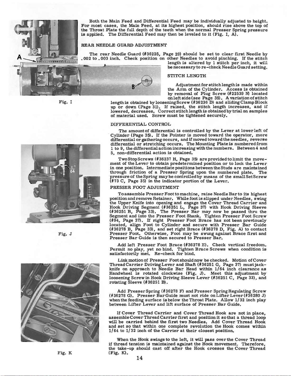
Both
most
Throat
the
cases,
Plate
Main
the
The
Differential
Feed
the
Main
full
and
Differential
Feed,
depth
Feed
of
at
the
may
its
teeth
Feed
highest
when
then
may
be
leveled
be
position,
the
normal
individually
should
Presser
to
it
(Fig.
adjusted
rise
I,
A).
above
Spring
to
height.
the
top
pressure
of
Fig.
Fig.
REAR
•
I
J
002
NEEDLE
The
to • 003
GUARD
rear
Needle
inch.
lengthis
up
or
lowered,
of
material
DIFFERENTIAL
The
Cylinder
differential
differential
1
to
9,
5,
non-differential
TwoStopScrews
ment
in
one
through
pressure
(1#73
C,
PRESSER
To
position
the
Upper
Hook
(1#36251
Segment
(1#94,
located,
(1#36278
Presser
Presser
Add
Permit
satisfactorily
Linkmotionof
Thread
knife
Handwheel
loosening
rotating
ADJUSTMENT
Guard
Check
down
thedifferentialactionincreasingwiththenumbers.
of
the
position.
Page
assemble
and
Driving
B,
Page
B,
left
no
Carrier
on
Sleeve
(#36225,
position
8
~
obtained
(Page
decreases.
used.
amount
friction
of
and
align
Foot.
Bar
approach
(Page
or
or
Lever
the
35)
FOOT
remove
Knife
Page
into
37).
Page
Guide
Presser
play,
met.
is
Screw
of
35).
gathering
stretching
Spring
Segment
Foot
Otherwise,
Driving
rotated
in
(1#36251
Page
on
other
length
be
necessary
STITCH
the
by
removal
on
bylooseningScrew
31).
Correct
Screw
CONTROL
differential
If
action
(1#36237
to
obtain
Intermediate
of a Presser
may
in
the
ADJUSTMENT
Presser
Retainer.
into
opening
33).
the
Presser
If
right
to
33),
and
is
then
Foot
yet
no
Re-check
Presser
to
Needle
Hook
left
If
raised,
must
the
Pointer
occurs,
occurs.
is
obtained.
H,
predetermined
be
controlled
indicator
Foot
to
and
(1#36251
The
Presser
Presser
Cylinder
set
Foot
secured
Brace
bind.
Footshouldnow
Lever
clockwise
Driving
B).
29)
should
Needles
is
altered
LENGTH
Adjustment
Arm
of
the
of
side
(see
(1#36236
the
stitch
length
be
tightened
is
controlled
is
moved
and
if
moved
The
Page
35)
positions
Spring
portion
machine,
While
foot
engage
L,
Page
Shank.
Foot
and
Brace
may
to
(1#36278
Tighten
bind.
Shaft
Head
(Fig.
Sleeve
Bar
secure
be
Presser
Foot
right
for
and
Bar
be
set
to
avoid
by 1 stitch
to
re-check
for
stitch
Cylinder.
Plug
Page
stitch
is
obtained
securely.
by
toward
toward
Mounting
areprovidedtolimit
position
between
upon
the
by
means
of
the
raise
is
slipped
the
Cover
37)
with
may
Tighten
Brace
(#36278
swung
E).
Brace
be
(#36251
within
J).
Lever
to
clear
pinching.
Needle
length
Screw
35). A
D)
and
length
the
Lever
the
Plate
or
the
Studs
numbered
of
Lever.
Needle
under
Thread
Hook
now
Presser
has
with
Presser
D,
against
Bar.
Check
Screws
checked.
G,
Page
1/64
Meet
(1#36251
first
Needle
If
the
per
inch,
Guard
is
Access
(1#22539
variation
slidingClampBlock
increases,
by
trial
at
the
operator,
needles,
is
numbered
Between4
to
lock
are
the
small
Bar
to
Needles,
Carrier
Driving
be
passed
not
been
Fig.
A)
Brace
vertical
when
Motion
37)
inch
this
clearance
adjustment
C,
Page
stitch
it
setting.
made
within
is
obtained
N)
located
of
stitch
and
on
samples
lower
left
more
reverse
from
the
move-
the
Lever
maintained
plate.
Set
Screw
its
highest
swing
Sleeve
thru
Foot
Screw
previously
Bar
Guide
to
contact
first
freedom.
condition
ofCover
mustjack-
33),
by
will
if
of
and
The
and
the
and
is
as
by
and
Add
Fig.
K
(#36278
when
the
between
If
Cover
assemble
will
be
and
set
1/64
to
When
if
thread
the
take-up
(Fig.
K).
PresserSpring
G).
Presser
feeding
Lifter
Cover
carried
so
1/32
the
tension
Thread
that
inch
Hook
should
surface
Lever
Thread
behind
within
is
(1#36278
BarGuide
and
Carrier
Carrier
the
one
of
the
Carrier
swings
maintained
cast
is
below
lift
first
complete
to
the
off
after
14
F)
must
the
surface
and
Cover
first
two
at
left,
against
the
and
Presser
not
Throat
of
Presser
Thread
and
position
Needles.
revolution
their
closest
it
will
the
Hook
SpringRegulating
ride
onLifterLever(/#36280
Plate.
pass
Hook
Bar
Hook
it
Add
the
position.
over
movement.
crosses
Allow
Guide.
are
so
that a thread
Cover
Hook
the
the
1/32
inch
not
in
Thread
comes
Cover
Therefore,
Cover
Screw
J)
play
place,
loop
Hook
within
Thread
Thread
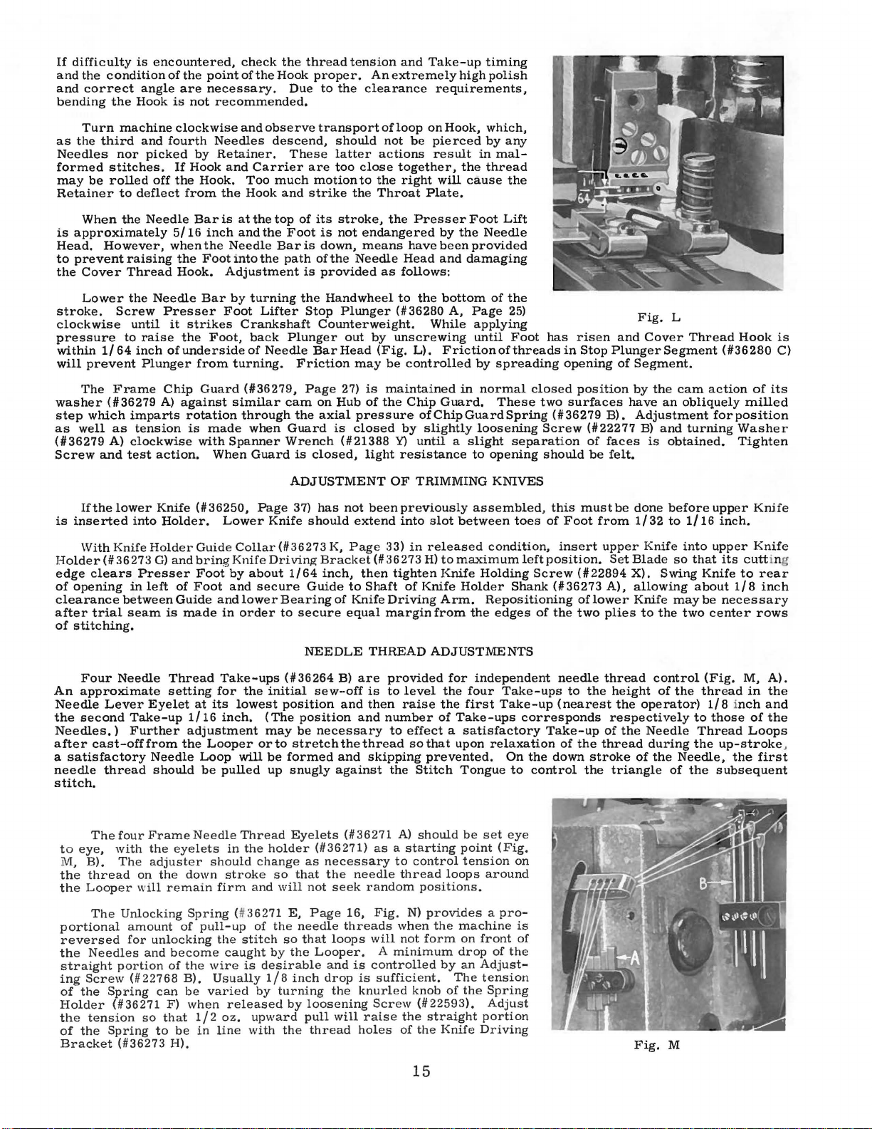
If
difficulty
and
the
and
bending
as
Needles
formed
may
Retainer
is
Head.
to
the
condition
correct
the
Turn
the
third
stitches.
be
rolled
When
approximately
However,
prevent
Cover
is
encountered,
angle
Hook
machine
and
nor
picked
off
to
deflect
the
Needle
raising
Thread
of
the
point
are
necessary.
is
not
clockwise
fourth
by
If
Hook
the
Hook.
from
Bar
5/16
inch
when
the
the
Foot
Hook.
check
the
of
the
Hook
observe
Carrier
Too
Hook
the
the
the
Due
descend,
These
much
and
top
Foot
Bar
path
recommended.
and
Needles
Retainer.
and
the
is
at
and
Needle
into
Adjustment
thread
proper.
to
transport
are
motion
strike
of
its
is
is
down,
of
is
provided
tension
the
should
latter
too
the
stroke,
not
the
and
An
extremely
clearance
of
loop
not
actions
close
together,
to
the
right
Throat
the
endangered
means
Needle
as
Head
follows:
Take-up
requirements,
on
Hook,
be
pierced
result
will
Plate.
Presser
by
have
been
and
timing
high
polish
which,
by
in
mal-
the
thread
cause
Foot
the
Needle
provided
damaging
any
the
Lift
Lower
stroke.
clockwise
pressure
within
will
prevent
The
washer
step
which
as
well
(#36279
Screw
is
Holder(#
edge
of
clearance
after
of
An
Needle
the
Needles.)
after
a
needle
stitch.
and
If
the
inserted
With
clears
opening
trial
stitching.
Four
approximate
second
cast-offfrom
satisfactory
the
Screw
until
to
1/64
inch
Frame
(#36279
imparts
as
tension
A)
clockwise
test
lower
into
Knife
36273
in
between
seam
Needle
Lever
Take-up
Further
thread
Needle
Presser
it
raise
of
Plunger
Chip
A)
action.
Knife
Holder.
Holder
G)
Presser
left
is
Thread
setting
Eyelet
Needle
should
Bar
strikes
the
Foot,
underside
from
Guard
against
rotation
is
made
with
(#36250,
Guide
and
bring
Foot
of
Foot
Guide
made
at
1/16
adjustment
the
Looper
Loop
be
by
Foot
Crankshaft
of
turning.
(#36279,
similar
through
Spanner
When
Lower
Collar
Knife
by
and
and
lower
in
order
Take-ups
for
the
its
lowest
inch.
will
pulled
turning
Lifter
back
Plunger
Needle
cam
when
Guard
Wrench
Guard
ADJUSTMENT
Page
Knife
(#36273
Driving
about
1/64
secure
Bearing
to
(#36264
initial
position
(The
may
or
to
be
formed
up
snugly
the
Handwheel
Stop
Plunger
Counterweight.
out
Bar
Page
on
Hub
axial
is
closed,
has
should
K,
Bracket(#
inch,
Guide
of
NEEDLE
B)
sew-off
position
necessary
and
against
Head
27)
(#21388
not
and
the
Friction
the
is
37)
secure
be
stretch
by
(Fig.
may
is
of
pressure
closed
light
been
extend
Page
then
to
Shaft
Knife
equal
THREAD
are
is
then
and
thread
skipping
to
the
(#36280
unscrewing
be
maintained
the
Y)
OF
33)
36273
tighten
Driving
margin
provided
to
number
to
the
bottom
A,
Page
While
L).
Friction
controlled
Chip
by
until a slight
resistance
TRIMMING
previously
into
in
of
level
raise
effect a satisfactory
so
Stitch
in
Guard.
ofChipGuardSpring
slightly
slot
between
released
H)
to
maximum
Knife
Knife
Holder
Arm.
from
the
ADJUSTMENTS
for
the
four
the
first
of
Take-ups
that
upon
prevented.
Tongue
of
the
25)
applying
until
Foot
of
threads
by
spreading
normal
loosening
to
assembled,
condition,
Holding
Repositioning
independent
closed
These
separation
opening
KNIVES
toes
left
Shank
edges
Take-ups
Take-up
corresponds
relaxation
On
the
to
control
has
in
opening
two
(#36279
Screw
should
this
of
Foot
insert
position.
Screw
(#36273
of
the
needle
(nearest
Take-up
of
down
risen
Stop
position
surfaces
B).
(#22277
of
faces
be
must
from
upper
(#22894
A),
of
lower
two
plies
thread
to
the
of
the
thread
stroke
the
Fig.
and
Cover
Plunger
of
felt.
be
Set
height
the
respectively
triangle
Segment
Segment.
by
the
have
an
Adjustment
B)
and
is
done
1/32
Knife
Blade
X).
Swing
allowing
Knife
to
the
control
of
operator)
the
Needle
during
of
the
obtained.
before
to
L
Thread
cam
obliquely
turning
1/16
into
so
that
Knife
about
may
be
two
(Fig.
the
thread
to
Thread
the
Needle,
of
the
Hook
(#36280
action
center
1/8 inch
of
milled
for
position
Washer
Tighten
upper
Knife
inch.
upper
Knife
its
cutt
to
1/8
necessary
M,
in
those
of
Loops
up-stroke
the
subsequent
is
C)
its
ing
rear
inch
rows
A).
the
and
the
,
first
The
four
to
eye,
M,
B).
the
thread
the
Looper will
The
portional
reversed
the
Needles
straight
ing
Screw
of
the
Holder
the
tension
of
the
Bracket
with
The
on
Unlocking
amount
for
and
portion
(1122768
Spring
(#36271
so
Spring
(#36273
Frame
the
adjuster
Needle
eyelets
the
down
remain
Spring (11
of
become
of
can
F)
that
to
be
H).
pull-up
the
B).
be
when
1/2
in
unlocking
in
should
stroke
firm
the
caught
wire
Usually
varied
released
oz.
line
Thread
the
holder
change
and
36271
of
stitch
by
is
desirable
1/8
by
upward
with
Eyelets
so
that
will
E,
the
needle
so
the
inch
turning
by
the
(#36271)
as
necessary
the
not
seek
Page
threads
that
loops
Looper.
and
drop
the
loosening
pull
will
thread
(#36271
as a starting
needle
random
16,
Fig.
will
A
is
controlled
is
sufficient.
knurled
Screw
raise
holes
A)
should
to
control
thread
positions.
N)
provides a pro-
when
the
not
form
minimum
knob
(#22593).
the
straight
of
the
by
Knife
be
point
tension
loops
machine
on
drop
an
The
of
the
set
eye
(Fig.
around
front
of
the
Adjust-
tension
Spring
Adjust
portion
Driving
on
15
is
of
Fig.
M

Fig.
Fig.
Fig.
Tension
four
needle
has
more
off,
the
#2, 3 oz.,
pull
through
bottom
that
illustrated
upon
the
fourth
and
even.
The
with
the
Plate
to
may
be
slightly
Eyelets
left
will
that
N
0
p
casting-off
descended
The
from
the
more
The
actual
should
during
and
condition
amount
more
tightly.
triangle
Cover
lower
determines
controlling
loops.
between
start
of
to
Needle
and
the
The
with a horizontal
wall
of
control
tension
results
CoverThread
described
When
six
Thread
Eccentric
(#36280
Discs.
tension
to
obtain
Before
into
reverse
removed.
tain
this
The
Insertion
to
obtain
slot}
will
Tension
Locking
has
been
(Needle
open.
connected
of
the
threads
tension
Needle
of
needle
Cast-off
Cast-off
are
tension
than
be
the
might
edge
The
rise
tension
the
and
may
in
E)
When
is
left
Discs
Screw
Bar
Release
Thread
#3, 3 oz.,
the
stroke. A light
(Fig.
material
loops
Only
another
used
to
without
increase
end
the
Bar
formation
the
an
position
of a large
the
made,
advantage
placed
from
7/64
inch
of
of
Cylinder,
flat
bed
tension
sufficient
take-up
of
yarn
be
An
formation,
Thread
of
Eyelet
the
amount
in
conjunction
Take-up
crossing
of
the
rise.
ofthe
Main
prevent
be
used
disturbance
Carrierand
under
ADJUSTMENT
Presser
Tensions
Shaft
operating against
the
obtained.
average
making
motion
Hold
or
end
of
correct
raise
the
while
(#22839
tighten
down}
Lifter
before
six
threads
is
seldom
than
the
other
Tensions
and
Needle
will
pulled
enough
LOOPER
(#36204}
Support
position
rotating
to
the
the
machines
selected
portion
desirable
excessive
COVER
Take-up
Needle
pull
Frame.
thread
to
Presser
(#35792
Presser
clearance
any
by
prop
during
Eccentric
Screwdriver
clockwise
bypullingfrom
adjusting.
#4, 3 oz.
Lever
Spring
0},
may
produce a balanced
up
tension
is
Plate
will
where
the
maximum
amount
the
sharp
from
its
Looper
is
to
prevent
of
or
thread.
especially
Eyelet
and
Cast-off
of
should
of
the
Bar.
Otherwise,
of
the
Cover
directly
Only
from
tighten
to
the
the
Foot
Foot
are
M,
Foot
The
orientation
adjustment,
lifting
up
Lifter
the
adjustment.
Pins
or
D)
in
Locking
Lever
is
individually
uniform
three.
Eyelet
be
and
THREAD
normally
(#36204
alter
Take-up
of
highest
Thread,
about 2 1/2
making a similar
after
the
cycle
at
some
tension
THREAD
thread
with
tension
be
thread
first
Threadis
from
Cover
first
CoverThread
Adjustment.
OF
is
raised
simultaneously
Detail
Pins
is
of
the
following
Shaft(#35792
decrease
rotation
(#36280
and
As
maybe
Tension
when
Scale
such
used.
the
second
to
pull
ADJUST:MENT
positioned
the
it
is
desired
right
position.
thread
corner
position
trials
thread
tension
being
will
from
but
An
increase
operation
will
while
ADJUSTMENTS
should
Plate
pulled
timed
by
The
Cast-off
needle
approximately 1 ounce
the
enough
stolen
Thread,
row
TENSION
by
21,
(#35792
down,
of
the
1/64
inch
the
Lifter
Lifter
Lever
procedure.
provide
Rotation
the
will
E)
S~rew
coneto
again
controlled.
as
usually
an
settothe
Further
up
A,
Fig.
Take-up
on
the
pulled
occurs
as
measured
ounces,
with
the
have a tendency
chaining.
be
set
(Fig.
off
the
to
the
will
thread
Eyelet
tension
of
stitching.
the
Page
K}
the
Discs
Eccentric
between
Lever
by
any
M}
counterclockwise
space
increase
to
turn
and
be
connect
the
average
is
the
as a postal
stitch
and
the
to
Main
off.
the
being
minimum
of
to
with
K}.
for
fullness
cast
Cover
should
remain
which
from
but
Hook
RELEASE
Foot
released
which
Mechanism
suitable
contains a Screwdriver
means
re-check
sure
first
condition
following:
measured
Needle
adjustment
having
third
stitch
with
P}.
Moving
timing
change
Shaft.
Moving
Time
when
the
•
by
which
stitch
material
stolen
tension
pull
3/32
Position
the
of
off
during
Thread
always
in
loop
is
is
used
Cone.
abnormally
ofthe
Lifter
25}
rotated
separate
clamp
Shaft
Pin
so
that
of
between
the
Shaft.
tension
Tension
Treadle
Tension
needle
for
#1, 3 1/2
by a horizontal
Bar
is
scale,
needle
should
the
these
with
depending
above
the
inch
cover
the
the
will
located
to
Adjustment
Presser
Mechanism,
by
and
all
means
rotating
space.
After
almost
similar
depending
the
loops
right
the
and
this
the
timing
The
Eyelets
the
Take-up
Needle
pulling
is
considerably
one
and
yarn
from
the
plies
to
disturb
gap
of
this
stitch,
cover
the
Hook
occur
Cover
be
impaired.
measured
in
effect
An
increase
high
means
by
the
the
thread,
may
be
Tension
must
be
lost
motion
and
the
(facing
the
Pins
adjustment
of
Discs
Chain
of
thread
sewing
oz.,
first
and
small
be
used.
end
flush
Cast-off
method
very
Thread
Bar
has
straight
Looper.
used
the
Cone
on
speed
normal
together
the
between
Eyelet
thus
stitch
interval
and
the
prior
Thread
the
left
thread
tension
of
the
Foot
the
of
Lever
Tension
and
varied
Disc.
forced
main-
Slot.
Shaft
the
and
Release
threads
are
not
if
dis-
the
at
to
to
so
in
is
an
is
16

The
1.
The
For
2.
The
:l.
Time
inch
4.
Place a Felt
(1136271 D).
are
lubricated
machine
Cast-off
sewing
Thread
the
Take-up
from
its
should
(#:l6204)is
without
Eyelets
highest
Pad
on
Saturate
and
INSTRUCTIONS FO.R
be
adjusted
normally
the
Retainer
on
the
so
that
casting
position.
top
of
the
this
will
felt
pull
(1136211),
Cast-off
machine
with
up a
better
AND
as
positioned
off
some
WITHOUT
per
the
Support
from
under
thread
stitch
SEWING
standard
with
move
the
Plate
the
sharp
the
needle
lubricant
on
plastic.
PLASTIC
THE
the
right
Cast-off (#36204)
(1136204 A)
corner
36211
adjusting
end
threads
such
WITH
RETAINER
should
occurs
NYLON
instructions,
flush
with
to
be
when
against
as
Clearco.
the
its
placed
the
the
back
THREAD
except
Cast-off
extreme
to
Needle
of
By
doing
Support
right
the
the
for
the
Plate (11
position.
maximum
Bar
has
Stitch
Unlocking
this,
the
followin
36204
right
position.
descended
needle
g:
A).
9/64
Bracket
threads
1.
2.
3.
4.
5.
6.
7.
8.
9,
1.
2.
3.
4.
5.
6.
7.
8,
9.
10.
11.
12.
After
the
Remove
Hemovc
Loosen
of
one
Hcmove
If
the
inside
this
surface
To
assemble,
Housing
right.
goes
between
graph
five
(1151493
Push
the
tighten
Pump
Shaft
be
set
Replace
sealer
it
is
desirable
When
the
the
In-take
Remove
being
replaced).
Remove
Remove
Remove
Remove
Loosen
Loosen
Assemble
Replace
with
the
Replace
Place
a.
Shaft
against
secure
with
, 001
Replace
top
covers
Oil
Pump
Assembly
both
Housing
Set
Screws
Pump
Oil
Pump
(1135897
Then
that
E)
on
Oil
Set
Screws
is
at 2 to 4 ounces
the
between
Pump
Filter
Bottom
Oil
Slinger
Oil
Wick
Oil
Tube
Ball
Holding
Holding
the
the
Oil
Tube,
the
Ball
009
Holding
inch
Bottom
in
Gear
(1151493
Driven
surface
with a fine
start
from
BN).
put
Oil
the
Oil
should
the
right
Pump
of
hard
to
two
Idle
the
Housing
to
put a bead
is
replaced
Screen
Cover
Screws
(11666-128).
(#36293 A).
Bearing
Screws
Screw
Bushing,
Oil
Wick
Bearing
inch
thickness
the
Gauge
Screws
oil
clearance
Cover
INSTRUCTIONS
have
been
removed,
from
Covers
Oil
of
Seal
Seal
be
Driven
Oil
Gears
Cap
in
(11666-128)
{1/36297 A
Pump
E,
Det.
Gear
(1/35897
the
Oil
file.
Next,
end
turn,
inch.
INSTRUCTIONS
(1136295
(1136295
Pump
(This
the
left
put
Ring
(11660-220,
Ring
and
smooth
of
Gear
Gear
Pump
Driven
as
it
)
(1151493
and
Covers.
of
II 1 Permatex
in
the
and
that
(1136295
(1122882 A).
Insert a screwdriver
(1136295
(1136295
Collar
Collar
Cap
(1136295
Gauge
and
Pin,
AE),
from
Z)
machine
Driven
7 ).
Housing
is
the
side
and
the
Oil
the
on
the
Shaft
(1135897
will
damage
E)
machine,
the
Z,
Det.
AC)
AE)
on
(1121705)
and
Ball
in
the
AC).
between
push
NOTE:
Bushing
and
Pulley
FOH
ON
follow
(Det. 1 thru
and
36297
Gear
BR).
surface
put
Pump
Det.
right
side
Housing
(1135897
BH)
Gear.
and
Just
along
care
Gear
FOR
IN
DRIVE
34,
from
end
Collar
and
Bearing
Oil
the
the
Ball
(1136295 Y),
INSTALLING
OIL
PUMP
procedure
.F',
Det. 1 and
{1/35897
(1/35897 BN,
the
(CAUTION:
put
be
on
REPLACING
Page
remove
Tube
To
(1136295 G
where
Pump
Driven
12A)
of
the
so
that a good
BP)
against
the
Driving
on
the
sure
the
must
the
UNIT
19)
into
of
Housing
of
Ball
on
(#36293 A)
Gear
Bearing
obtain
BR,
next
and
the
joint
be
lV!ainshaft
and
Bearing
Collar
the
Locating
OIL
outlined
23 ).
13,
11)
\\'asher
Shaft
(1135897
(1135897
the
Gear.
Housing.
seal
on
Seal
not
compress
Covers
the
Cover
to
be
is
not
SHAFT
CK)
Tube,
remove
(11660-302)
Bushing
Shaft
and
secure
Pin (11
Collar
to Holding
H)
SEAL
and
BR)
is
the
Ring
35897
are
sure
tilt
36295
and
SHAFT
as
20,
Page
Det.
Det. 10lis rough
the
Steel
Gear
Gear
to
Pump
press
the
Oil
Do
Gear (11
Housing
surfaces
of
taken
GEAR
(29480
Pulley (#36295 G or
the
and
and
new
Holder
access
or
36295
lUNG
below:
Page
23).
press
Gear
Shaft
or
grooved,
of
the
seal
BP)through
on
the
The
(This
obtained. ) Place
Shaft
and
BY)
(1136297 A
clean.
and
too
(36295
slightly,
entire
(1136295 Y).
and
the
away
fill
shaft
Steel
Washer (11
is
the
until
there
Washer
the
Oil
on
the
and
After
the
Housing.
that
the
against
W)
36295
and
Shaft
remove
the
Bushing
and
from
Cylinder
assembly
the
center
tight
and
put
AB)
Screws (11
with 3 ounces
(1135897
it
is
contacts
the left
with
surface
another
is
so
that
Seal
Ring
Mainshaft.
36297
the
Covers
the
H,
depending
lift
the
assembly.
Ball
(1136295 Y)
Gear
as
95)
secure
of oil.
desirable
the
Pump
side
the
screw
6042 A,
mentioned
no
end
it
enou
F).
Suction
Gear
Tube
Bearing
into
Shaft.
far
as
Collar (11
BP,
of
Oil
Pump
shake
is
snu
gh
Torque
Do
not
are
Tube
on
on
out.
from
the
in
the
Holding
possible
Det.
8)
to
smooth
Housing.)
the
Pump
hub
to
Det.
12B)
in
para-
Gear
or
bind.
g.
Then
so
that
should
use
tightened,
enters
the
Pump.
the
Shaft
Shaft.
Housin
Housin
21705)
out
the
the
any
g.
g
the
and
To
Holding
the
Shaft
Bottom
remove
Screws
in
this
Cover
excessive
in
Collar
position,
(1136295
(1121705).
push
Z),
HElVIOVING
end
play
the
in
Push
Collar
EXCESSIVE
either
the
against
Gear
Gear
Shaft
the
PLAY
Shaft
toward
Bushing
FROM
(1136295 W),
the
Pulley
(1136295 Y)
GEAR
remove
end
and tighten
17
SHAFT
Bottom
as
far
Cover (11
as
it wi
Screws
ll
in
36295
go
and
Collar.
Z).
while
Replace
Loosen
holding
the

1
~
-----1
-L 1
-
8
(.~
4,
l$
·
~
-
...
3 (
2
J
18

FOR
STYLES 36200 A AND B ONLY
Ref.
Part
No. No.
1
2
3
4
5
5A
6
7
8
9
10
11
12
13
14
15
16
17
18
19
20
21
22
23
24
25
26
27
28
29
30
31
32
33
34
35
36
37
651
21371
660-275
660-161
35895
21261 M-210
29480
22571 A
22569 c
36295 AC
36295 AD
36295 AE
660-302
21705
22894
36295 y
36295 v
36295
666-96
36295
22882 A
36295 H
36295
22894 v
61321 J
61321 L
22574
36295 G
22650
22894 X
36295
36293 A
666-128
36295
22569 c
22652
36295 J
38
B-24
UE
R
CK
51-120
c
AB
w
F
AE-4
AA
z
F-20
25
s
DRIVE UNIT,
Nut
Washer
Neoprene
Felt
Mounting
Vee
Auxiliary
Blk.
Screw-----------------------------------------Belt
Screw------------------------------------------
BELT
GUARDAND MOUNTING STUD
Description
--------------------------------------------
---------------------------------------Isolator
-------------------------------
Isolator------------------------------------
Stud-----------------------------------
Belt,
21
inch
Support
outside
and
Drive
circumference-----------
----------------------
Screw--------------------------------------
Oil
Gauge
----------------------------------
Screw-------------------------------------Ball
Bearing
Gasket
-------------------------------------
Cap----------------------------
Screw-------------------------------------Ball
Bearing--------------------------------
Collar--------------------------------------
Screw----------------------------------
Bushing
Machine Support
Gear
Oil
Gear
------------------------------------
----------------------------
Locating
Filler
Pin---------------------------
Plug------------------------------
Shaft---------------------------------Screw-------------------------------------Handwheel
Pulley
Assembly
------------------------
---------------------------------
Screw-----------------------------Handwheel-----------------------------Spacer
Plate----------------------------
Screw----------------------------------
Variable
Speed
Socket
Pulley------------------------
Set Screw
------------------------
Screw----------------------------------
Gasket
Oil Tube
Oil
Bottom
-------------------------------------
-----------------------------------
Wick
-----------------------------------
Cover-------------------------------
Screw--------------------------------------
Guard
-------------------------------------
Amt.
Req.
6
6
6
9
3
1
1
2
1
6
2
2
4
2
2
2
2
1
1
1
2
2
1
1
2
1
1
3
1
1
2
1
2
2
1
8
2
1
2
19

20

MAIN
FRAME, MISCELLANEOUS COVERS, BUSHINGS
AND
TAKE-UP
Ref.
No.
1
2
3
4
5
6
7
8
9
10
11
12
13
14
15
16
17
18
19
20
21
22
23
24
25
26
28
28
28A
29
30
31
31A
32
33
34
35
36
37
38
39
40
41
42
43
44
45
46
47
48
49
50
51
52
53
54
55
56
57
58
59
60
61
62
63
64
65
66
67
Part
No.
p
35888
93
35888 N
666-96
50-537 Blk.
22516 A
93
A
90
35887 X
35887
AE
50-537 Blk.
666-96
22516 A
22539 M
35887 AD
12934 A
41071 G
35887 M
35887 R
22564 B
93
50-533 Blk.
36280 B
41394 A
22733 B
35889 H
CL21
36290
56390 E
22569 B
22539 T
36260
CL21
35760 D
69
H
22711
35890 E
35761 D
36290 A
62271 B
35781 D
36290 B
36281
22829
22839
c
73
36256 A
36256
22
KH
36204
52958 F
A
73
52958 c
36204 A
v
35887
35887 z
22564 B
22791 D
36271 D
36271 E
36271 F
22593
22596 D
36271
28
c
73 A
22799 B
22768 B
36271 A
Description
Gasket------------------------------------------------------------Screw-------------------------------------------------------------Crank
Chamber
OilCup
Oil Sight Gauge
Cover-----------------------------------------------
--------------------------------------------------------
------------------------------------------------Screw-------------------------------------------------------------Screw-------------------------------------------------------------Screw--------------------------------------------------------------
Cover,
Top
Cove~
Top
Oil Sight Gauge
Oil Cup
Screw--------------------------------------------------------------
Plug
Screw
Gasket-------------------------------------------------------------
middle--------------------------------------------------
front----------------------------------------------------
-------------------------------------------------
--------------------------------------------------------
---------------------------------------------------------
Nut---------------------------------------------------------------Nut---------------------------------------------------------------Spring--------------------------------------------------------------
Middle
Screw--------------------------------------------------------------
Cover
Hinge
------------------------------------------------Screw--------------------------------------------------------------
Oil Sight Gauge
Presser
Foot
-----------------------------------------------------
Lifter
Stop
Plunger
Bushing-
-----
----------------------Gasket------------------------------------------------------------Oil
Drain
Screw-----------------------------------------------------
Oil Shield
Oil
VVick
Bushing Housing, including
Bushing Housing
----------------------------------------------------------
----------------------------------------------------------bushing------------------------------------
Gasket----------------------------------------------
Screw--------------------------------------------------------------
Plug
Screw
Needle
Oil
VVick
Needle
VVasher
Screw-------------------------------------------------------------Crankshaft
Bushing Cap
Main
Shaft Bushing,
Thread
Looper
Main
Shaft Bushing,
Looper
---------------------------------------------------------
Lever
Lever
Shaft Bushing,
-----------------------------------------------------------
Shaft Bushing,
rear-------------------------------------
front-------------------------------------
-----------------------------------------------------------Bushing,
--------------------------------------------------------
Guide
-------------------------------------------------------
Thread
Thread
front--------------------------------------------
rear
--------------------------------------------
Guide
VVire
front
-------------------------------------------
--------------------------------------------
Shield------------------------------------------------
Screw--------------------------------------------------------------
Screw--------------------------------------------------------------
Screw-------------------------------------------------------------Cover
Cover
Thread
Thread
Take-up-----------------------------------------------
Take-up
Eyelet----------------------------------------Screw-------------------------------------------------------------Cast-off------------------------------------------------------------
Cast-off
Plate
Eyelet,
rear
------------------------------------------
Screw-------------------------------------------------------------Cast-off
Cast-off
Gasket
End
Plate
Eyelet,
Plate
-------------------------------------------------------------
Cover----------------------------------------------------------
------------------------------------------------------
front
------------------------------------------
Screw-------------------------------------------------------------Screw-------------------------------------------------------------Stitch Unlocker Mounting
Unlocking Spring
Spring
Holder-------------------------------------------------------
----------------------------------------------------
Bracket
-------------------------------------
Screw-------------------------------------------------------------Screw-------------------------------------------------------------Needle
Thread
Eyelet------------------------------------------------
Screw---------------------------------------------------------Screw-------------------------------------------------------------Screw--------------------------------------------------------------
Screw--------------------------------------------------------------
Frame
Needle
Thread
Eyelet
-----------------------------------------
Amt.
Req.
1
5
1
1
1
4
2
2
1
1
1
1
6
1
1
2
2
1
1
3
2
1
1
1
1
1
1
1
1
3
2
1
2
1
1
1
1
1
1
1
1
1
1
2
2
1
1
1
2
1
1
2
1
1
1
1
4
1
1
1
1
1
1
1
4
2
1
1
4
21

22

Hef.
No.
4
10
lOA
11
12
12A
12B
13
14
15
16
17
18
19
l9A
20
21
22
23
23A
24
25
26
27
28
29
30
31
32
33
34
35
36
37
38
39
40
41
42
43
44
45
45A
46
46A
47
48
49
50
51
52
53
54
55
56
57
58
59
60
61
62
63
64
65
66
67
68
1
2
3
5
6
7
8
9
Part
No.
36297 J
35897
35897
35894 J
660-207
22585 A
51493 E
35897
21756 G
35897
35897
35897
89
660-220
6042
36297 A
22571 B
90
80265
36261 A
35861 D
35894 L
660-202
36297 E
29101 J
22587 E
22894
22894 w
29103 T
22587 E
22894 w
22894 w
36223
22580
22801
36223 A
22580
35895 L
531
35895 X
22519 F
80265
22894 K
22894
22797
35897
35895 y
531
36221 c
36221 B
22894 H
22894 E
22894 X
22650
AE-4
660-202
36251 M
22766
36251 N
36263
36222 A
35763 G
36222
35763 F
35862
22587 B
35763
77
35815 A
22596 B
22729
77
36264 D
51054
22564
51254
J
22562 A
56354 A
660-219 p
NEEDLE LEVEH,
BV
BU
BP
BN
BW
BH
A
w
J
BY
Screw-------------------------------------------------------------------------Needle
Crankshaft
c
Needle
Main Shaft
Needle
Needle
Needle
Screw--------------------------------------------------------------------------
Needle
Screw-------------------------------------------------------------------------Needle
Link
Screw--------------------------------------------------------------------------
Needle
Needle
Roll
MAIN
SHAFT, CRANKSHAFT AND MISCELLANEOUS OILING
Amt.
Description
Cover
and O
il
Housing
In-take
Reservoir
Oil
Reservoir,
Oil Seal
Screw--------------------------------------------------------------------------
Gear
Gear
Vent
Oil
Pump
Gasket------------------------------------------------------------------------Oil
Pump
Screw
Oil
Seal
Washer
Housing
Plug
Screw
SpacerWasher
Take-up
Gasket---------------------------------------------------------------------
~~
~::~~~~r~!~~~~-================================::::::::::::::::::::::::::::
In-take
Feed
Screw
SetScrew------------------------------------------------------------------
Set Screw
Feed
Screw
Set Screw
Set Screw
Double Disc
Screw---------------------------------------------------------------------Screw-------------------------------------------------------------------------Cover
Screw---------------------------------------------------------------------Crankshaft
Screw---------------------------------------------------------------------l\1
ain
Screw----------------------------------------------------------------------
Washer
Spot Screw
Set Screw
Scr
w-------------------------------------------------------------------------Pump
Crankshaft
Screw---------------------------------------------------------------------Pulley,
Pulley,
Spot Screw,
Set
Screw,
Screw,
Oil Seal Ring
Eccentric
Needle
Screw----------------------------------------------------------------------
Screw---------------------------------------------------------------------Screw----------------------------------------------------------------------
Pin------------------------------------------------------------------------
Screw----------------------------------------------------------------------
Filter
Outlet
back-------------------------------------------------------------
Ring-------------------------------------------------------------------
--------------------------------------------------------------------------
Shaft
---------------------------------------------------------------------
Screw---------------------------------------------------------------------
Housing---------------------------------------------------------------
Driven
---------------------------------------------------------------------
Ring
-------------------------------------------------------------------
-----------------------------------------------------------------------Cover
and
Screw-----------------------------------------------------------------
------------------------------------------------------------------------Shield
Assembly
Filter
Drive
Lift
Thread
Shaft
Driving
Bearing
Bearing
Bearing
Bearing
Lever
Lever
Lever
Lever
Bar
Bar
------------------------------------------------------------------
Eccentric
---------------------------------------------------------------------
------------------------------------------------------------------
Eccentric
---------------------------------------------------------------------
------------------------------------------------------------------
------------------------------------------------------------------
Take-up
Take-up-----------------------------------------------------------
Thrust
Coupling--------------------------------------------------------------
--------------------------------------------------------------------
------------------------------------------------------------------
Gear--------------------------------------------------------------
Thrust
for
Styles
variable
Screw,
for
for
No. 36221 B
for
No. 36221 B
-------------------------------------------------------------------
Bearing---------------------------------------------------------------
Retaining
Rollers
--------------------------------------------------------------------Retaining
--------------------------------------------------------------------Rollers
Connecting
Connecting Rod
-------------------------------------------------------------------
Thread
Connection----------------------------------------------------------Link-----------------------------------------------------------------
Tubes, rear
--------------------------------------------------------------
Tube-----------------------------------------------------------
Gear-----------------------------------------------------------
Oil
Tubes,
-----------------------------------------------------------------
Collar
-----------------------------------------------------------------
Collar
36200 AA, AB
pitch,
for
--------------------------------------------------------
Assembly
Assembly----------------------------------------------------
------------------------------------------------------------
--------------------------------------------------------
--------------------------------------------------------
for
Styles
No. 36221 C
No. 36221
Eyelet------------------------------------------------------
(.255-40
(5/16-18
Plate
----------------------------------------------------------28
Ring----------------------------------------------------
----------------------------------------------------------28
Rod-----------------------------------------------------
-----------------------------------------------
front-----------------------------------------------
-------------------
-------------------------------------------------36200 A, B
-------------------------------------------------
C---------------------------------------------------
---------------------------------------------------
Pin
-------------------------------------------------
---------------------------------------
Thd.)---------------------------------------Thd.)
----------------------------------------
-------------------------------
Req.
1
1
1
1
1
6
4
1
2
1
1
1
2
1
1
1
1
2
1
1
1
~
1
1
2
1
1
1
2
1
1
1
2
2
1
2
1
2
1
3
3
2
4
3
1
1
2
1
1
1
1
2
2
1
1
2
1
1
4
1
1
2
1
2
1
2
2
1
1
2
1
1
1
1
Pin------------------------------------------------------------------------ 1
23

\
33
\
\
\
\
74
"'rs-
75
24

FOOT
LIFTER
AND
TENSION
PARTS
Ref.
No.
1
Part
No.
35880 c
2 86
86
3
36280 E
36280
4 22839 D
5
6
7
36280 G
36280 F
660-254
8 22517
9 94
10
11
12
13
22517
255
36280 H
35892-6
14 35792 s
17 35792 K
18 22562 A
19 35792 E
20 35792 c
21
22
23
35792 M
36280 D
36280 c
23A 258 A
24
36280 A
25 88 B
26
108
27 107
28 51292 F-2
51292
F-4
51292 F-5
29 35792
30 109
31 35792 H
32
36294
33 22585
B
c
34 86
to
35880 M
36278
36278
36278
80
J
c
G
F
35
36 22894
37
38
39
40
c
De
scription
Lifter
Screw~
Screw~
Presser
Presser
Screw
Lifter
Presser
36200
Retaining
Screw
Screw
Screw~
Screw~
Presser
36200
Tension
Tension
Tension
Screw
Tension
Lever
for
for
Link-------------------------------
Styles
Styles
Bar
Bar
Lifter
Lifter
36200
36200
A
AA
Lever,
Lever1 for
B
--------------------
1
AB------------------
1
for
Styles
Styles
-----------------------------------------
Lever
AI
Connecting
Foot
Connection
Link1 for
Lifter
Lever1 for
Styles
B------------------------------------
Ring~
for
Styles
36200 A1 B-------------
-----------------------------------------
----------------------------------------for
Styles
for
Styles
Foot
AI
B------------------------------------
36200 A1 B--------------------36200
Lifter
A
1
Bearing
B---------------------
Bracket1 for
Support---------------------------------
Thread
Disc
Eyelet---------------------------
Release
Pin------------------------
-----------------------------------------
Plate
Bracket---------------------------
Spring----------------------------------------Tension
Stop
Stop
Release
Plunger
Plunger
Shaft
Segment
Segment
---------------------------
Pin------------------------
---------------------------
Nut-------------------------------------------Presser
Foot
Lifter
Stop
Plunger-----------------
Screw-----------------------------------------Tension
Tension
Tension
Tension
Tension
Tension
TensionDisc
Tension
Oil
Nut
------------------------------------
Post
Spring~
Spring1 looper
Spring1 needle
Ferrule----------------------------
cover
thread---------------------
thread-------------------thread--------------------
Disc1 large-----------------------------
small-----------------------------
1
Post
-----------------------------------
Guard-------------------------------------Screw-----------------------------------------Screw------------------------------------------
Lifter
Lever
Link
Connection---------------------
Screw-------------------------------------Presser
Presser
Bar
Bar
Guide
Stud--------------------------
Regulating
Screw--------------------
Spring----------------------------------------See
following
page
36200 A1 B---
36200
A~
AB-
36200 A1 B--
Styles
Styles
Amt.
Req.
1
1
2
1
1
1
1
1
2
2
2
1
1
1
1
3
7
6
2
1
1
1
1
1
1
1
6
6
1
1
4
6
6
6
1
1
1
1
1
1
1
1
25

26

DETACHABLE
HEAD,
COVERS,
NEEDLE
BAR,
NEEDLE
BAR
HEAD
Ref.
No.
1
40
41
42
43
44
45
46
47
48
49
50
51
52
53
54
55
56
57
58
59
60
61
62
63
64
65
66
67
68
69
70
71
72
73
74
75
76
77
78
79
80
to
39
36278
22653
22560
36289
22524
36218
22738
36211-029
36211-027
36211-025
35817
36229
36278
35859
35859
36251
660-261
35767
22524
6042
22759
36289
36289
22524
36264
28
36264
28 A
28
51259
36280
22513
36294
36279
36279
22777
36279
22881
36278
6042
318
664
118
Part
No.
B
A
D
c
D
A
A
B
B
A
J
c
A
B
B
A
D
E
B-8
A
F-16
A
A
H
GAS-029
BY
Description
See
preceding
Detachable
Presser
Needle
Needle
Cover
Sleeve
Retaining
Sewing
Screw-------------------------------------
VVasher---------------------------------------
Screw----------------------------------------Baffle
Head
Screw----------------------------------------Needle
Screw-----------------------------------------
Needle
Screw----------------------------------------Screw-----------------------------------------
Cover
Presser
Plate
Cover,
Thread
Thread
Thread
Bar
page
Sewing
Bar
Bar
Bar
Thread
Bushing----------------------------
Head
----------------------------------front------------------------------
Lifter
Head-------------------------
Bushing------------------------
Bushing,
Bushing,
Carrier
Ring
Key----------------------------
Strike-off
Take-up-------------------------
Eyelet
Lever-----------------------
upper
lower
--------------------------
Pin--------------------
---------------------------
------------------
------------------
and
Hook
Driving
Screw-----------------------------------------
Oil
Deflector
VVasher
---------------------------------------
----------------------------------
Spring---------------------------------------Screw-----------------------------------------
Frame
Chip
Guard
-----------------------------
Screw-----------------------------------------
Presser
Presser
Foot
Foot
Guide,
Guide,
right
left------------------------
----------------------
Screw-----------------------------------------
VVasher
---------------------------------------
Screw-----------------------------------------
Taper
Pin-------------------------------------
Screw-----------------------------------------
Detachable
Head
Cover,
left---------------------
Screw-----------------------------------------
Needle
Retainer,
Retainer,
send
Retainer,
send
Needle---------------------------------------Needle
Bar
Screw
and
and
Bar
Head-------------------------------
-------------------------------------
marked 11029
marked 11027
charge
marked 11025
charge
marked 11CN
'
11
,
furnished
11
,
available
------------------------------
11
,
available
------------------------------
11
----------------------
with
as
as
machine
extra
extra
--
Amt.
Req.
1
1
1
1
1
1
2
2
2
2
1
1
2
4
2
1
4
1
1
1
1
1
1
1
1
1
1
1
1
2
1
1
1
1
1
4
1
5
1
1
1
4
1
27

_L_
0 I
24
30
28

DIFFERENTIAL
FEED
BAR,
ECCENTRIC
MAIN
FEED
ASSEMBLY
BAR,
FEED
LIFT
Ref.
No.
1
2
3
4
5
6
7
8
9
10
11
12
13
13A
13B
14
15
16
17
17A
17B
17C
18
19
20
21
22
23
24
25
26
27
28
29
30
31
32
33
34
35
36
37
Part
36236 A
36237
22504
36237 A
22845
36236
36234 D
36234 A
36234 B
22570
22528
36226
>.'<36226
>:<36226
•:'36226
36225
22528
36205 A
•:'36205 B
>:C36205
•:'36205 D
35884
36234
36234
22570
36234
36236
36236
36236
33174
62238
29478
29103
22587
22894
22894
269
36244
36244
to
7 5
No.
660-207
c
M
F
A
A
B
c
D
87
u
c
K
B
A
c
H
G
E
B
A
cs
T
E
w
w
18
A
97
A
Description
Oil
Seal
Ring-----------------------------------------
Feed
Differential
Screw
Differential
Screw
Differential
Feed
Differential
Screw
Differential
Differential
Differential
Differential
Screw
Needle
Screw
Main
Main
Main
Main
Lower
Main
Feed
Bushing---------------------------------------------Driving
Main
Screw
Link
Feed
See
Rocker
-----------------------------------------------
-----------------------------------------------
Bar
Feed
Screw
-----------------------------------------------
for
medium
for
light
left
hand
right
medium
light
use
use
hand
----------------------------------------------Guard,
-----------------------------------------------
Feed
Feed
operations
Feed
with
Feed
with
Lint
Feed
Feed
Screw
Bar
Link
Feed
-----------------------------------------------
Pin---------------------------------------------
Lift
Feed
Set
Screw----------------------------------------
Nut,
Connecting
Nut,
Ball
following
Shaft
Feed
Feed
Feed B·ar
Eccentric
Feed
Bar
------------------------------------------Feed
Feed
operations----------------------------------
Feed
offset--------------------------------------
Feed
offset
Dog,
to
heavy
Dog,
Dog,
No.
Dog,
No.
Shield
Bar
Bar
-------------------------------------------
Slide
Stud-------------------------------------
Bar
Eccentric
Lift
Screw
Set
Screw------------------------------------
left
thread
right
Joint,
Screw
page
------------------------------------
Adjusting
Adjusting
Driving
Stud
Bar---------------------------------
Plate-----------------------------------
Dog,
to
heavy
operations-----------------------
Dog,
Dog,
Dog,
------------------------------------
marked
marked
operations
marked
-------------------------------------
marked
36226 C differential
marked
36205 D differential
------------------------------------
---------------------------------------
Plate-----------------------------------
Block----------------------------------
Driving
Assembly--------------------------
Eccentric
---------------------------------------
----------------------------------
Rod-----------------------------------
thread
complete
---------------------------------------
---------------------------------
Lever---------------------Link
Link
------------------------------
marked
marked
marked
marked
''FZ"
"PK",
"PL",
''PM",
''FP",
Link
Assembly
------------------------------
''FV", 14
''PB",
''PF",
''FN", 14
---------------------------
14
-------------------------16
14
14
---------------------------
-----------------------
---------------------
16
14
teeth
teeth
teeth
feed
teeth
feed
Ball
teeth
teeth
teeth
teeth
per
per
per
dog
per
dog
Joint
per
inch,
per
inch,
per
inch,
per
inch,
inch,
inch,
inch,
inch,
for
for
for
------------for
-------------
------------
Amt.
Req.
1
1
1
1
1
1
1
1
1
1
2
1
1
1
1
1
1
1
1
1
1
1
1
1
1
1
2
1
2
2
1
1
1
1
1
2
1
1
1
1
1
1
2
>.'<
Available
as
an
extra
send
and
charge
item.
29

8
4n..
64
30

FEED
DRIVE
ASSEMBLY,
LINK
FEED
BALL
ROCKER,
JOINTS
LOOPER A VOID
Ref.
No.
1
37
38
39
40
40A
41
42
to
Part
No.
36
29478
29101
22587
22894
22894
269
43246
E
w
W
43 18
44
45
46
47
35846
22729
41255
22747
c
B
48 77
49 22711
50
51
52
53
54
660-207
36236
36236
36236
36236
B
J
K
55 62238 A
56
57
58
36236
36236
36236
D
H
c
59 258
60
61
62
63
64
6042 A
35746
35766
36236
660-207
A
B
B
65 22711
66
67
68
69
70
35766
35842
36236
660-207
29478
B
J
A
DM
71 56341 F
72 35851 K
73
35851
M
CT
J
Description
See
Feed
preceding
Drive
Feed
page
Assembly--------------------------------
Drive
Eccentric
Assembly
-----------------Screw-------------------------------------Set
Screw-----------------------------------
SetScrew--------------------------------------
Nut,
Connecting
Nut,
Ball
left
right
Joint
thread
---------------------------------
Rod
---------------------------------
thread--------------------------------
--------------------------------------
Screw--------------------------------------
BallFork
------------------------------------------
Screw---------------------------------------------Screw---------------------------------------------Screw---------------------------------------------Oil
Seal
Ring----------------------------------------
Bushing
Differential
Differential
Feed
Link
Driving
Bushing
Feed
Nut
Washer
Washer
Nut
Bushing
Oil
-------------------------------------------Driving
Feed
Link
Driving
Stud-------------------------
Link
Slide
Block
Rocker----------------------------------------
Pin--------------------------------------------
Link
Rocker
Screw----------------------------------
--------------------------------------------
Driving
Link----------------------------
------------------------------------------------
--------------------------------------------
--------------------------------------------
------------------------------------------------
--------------------------------------------
Seal
Ring----------------------------------------
Screw----------------------------------------------
Nut
------------------------------------------------
Feed
Feed
Oil
Looper
Drive
Drive
Seal
Ring
Drive
Assembly
Ferrule
and
Shaft
Looper
------------------------------------
Avoid
Drive
Lever
--------------------------------------Shaft
Cross
Head
Connecting
-----------------------------------------
----------------------------------------
Screw-----------------------------------------Connecting
Rod----------------------------------
-------------
-------------
Rod
Amt.
Req.
1
1
2
1
1
1
1
1
1
2
1
1
2
1
1
1
1
1
1
1
1
1
1
1
1
1
1
1
1
1
1
1
1
1
1
2
2
1
31

32

Ref,
No,
1
2
3
4
5
6
7
8
9
10
11
12
12A
12B
12C
13
14
15
16
17
18
19
20
21
22
23
24
25
26
27
28
29
30
31
32
33
34
35
35A
36
37
38
39
40
41
42
43
44
45
45A
46
47
48
49
50
51
52
53
54
55
56
57
58
59
60
61
62
63
64
65
65A
66
67
68
69
70
71
72
73
74
Part
No,
36249
36248
22652 A-6
1096 B
22564 D
22585 A
36208 A
604
36210
B
36251
36273 M
36273 F
605 A
J
36273
660-219 D
12934 A
B
52848
22729 c
18
36251 p
97 A
36278 B
22585
H
52841
12934 A
c
52848
22729 c
36 G
36261
660-202
269
4761
c
36251
22585
36273
c
36273 K
22562 A
36273 A
1096 B
22799 N
36273 D
36270
G
36273
22767 A
X
22894
35751 G
22572 B
36249 B
22729 D
652 C-9
c
36278
41255 B
22747
660-221
B
36253
29478
cu
35851 L
22729 c
269
4761
18
391.f5 A
A
97
61342
88
36253 A
258 A
77
15037 A
52336
660-215
269
DR
29478
36253 J
36253 H
660-311
20
36253 G
22795 B
660-219 p
LOOPER
Looper
LooperHolder---------------------------------------------------------------------
Screw
Looper
Screw
Looper
Cover
Knife Driving
ROCK
SHAFT, LOOPER DRIVE
Rocker Shaft
------------------------------------------------------------------------
Screw
Looper
Screw
Adjusting
------------------------------------------------------------------------
----------------------------------------------------------------------------
---------------------------------------------------------------------------
----------------------------------------------------------------------------
Guard---------------------------------------------------------------------
Thread
---------------------------------------------------------------
Screw
--------------------------------------------------------
Carrier
Bracket--------------------------------------------------------------
and Hook Driving Sleeve
AND KNIFE
Descr
iption
DRIVE PARTS
-----------------------------------
Bushing-----------------------------------------------------------------------
Screw
------------------------------------------------------------------------
Knife
RollPin--------------------------------------------------------------------------
Holder
Guide
Plate
-------------------------------------------------------
Nut------------------------------------------------------------------------------Knife Drive Connection
Screw
Nut------------------------------------------------------------------------------Cover
Presser
Nut-------------------------------------------------------------------------------
------------------------------------------------------------------------
Thread
Screw
Screw
Carrier
------------------------------------------------------------------------
Bar
Guide-----------------------------------------------------------------
------------------------------------------------------------------------
Ball
Joint,
left-----------------------------------------------
and Hook Driving Connecting Rod
Ball
Joint----------------------
Nut------------------------------------------------------------------------------Knife Drive Connection
Screw
------------------------------------------------------------------------
\Vasher-----------------------------------------------------------------------
Knife Drive
Oil Seal
Lever
Ring----------------------------------------------------------------------
Ball
Joint,
right----------------------------------------------
-----------------------------------------------------------------
Nut------------------------------------------------------------------------------Knife Drive Connecting
Sleeve Driving
Screw
Knife Holder
Knife
Holder
Screw
Knife
Holder
Screw
Screw
----------------------------------------------------------------------------
Knife
Support----------------------------------------------------------------------
Knife,
upper
Knife
Holder----------------------------------------------------------------------
Screw
----------------------------------------------------------------------------
Screw
----------------------------------------------------------------------------
Looper
Shaft
Lever---------------------------------------------------------------
------------------------------------------------------------------------
Spring---------------------------------------------------------------Guide
-----------------------------------------------------------------------Shank-----------------------------------------------------------------
------------------------------------------------------------------------
----------------------------------------------------------------------
Collar----------------------------------------------------------------
Rod---------------------------------------------------------
Collar
----------------------------------------------------------
Screw------------------------------------------------------------------------
Looper
Shaft
Sleeve---------------------------------------------------------------Screw-----------------------------------------------------------------------\Vasher-----------------------------------------------------------------------
Stud - Ball
Screw
Oil
---------------------------------------------------------------------------
Fork-------------------------------------------------------------------------
----------------------------------------------------------------------------
Seal
Ring---------------------------------------------------------------------LooperDriveLeverShaft----------------------------------------------------------Looper
Drive
BallJoint,
Nut---------------------------------------------------------------------------
Connecting
Upper--------------------------------------------------------------
Screw
-------------------------------------------------------------------Rod----------------------------------------------------------------
Connecting Rod
Assembly----------------------------------------------
Nut---------------------------------------------------------------------------
Ball
Joint,
lower
--------------------------------------------------------------
Screw
Collar----------------------------------------------------------------------------
Screw
Looper
Drive
--------------------------------------------------------------------
-----------------------------------------------------------------------Lever----------------------------------------------------------------
Nut-------------------------------------------------------------------------------
Screw
----------------------------------------------------------------------------
Nut-------------------------------------------------------------------------------
Li
nkPin-------------------------------------------------------------------------Retaining
Nut-------------------------------------------------------------------------------
Looper
Ring---------------------------------------------------------------------
Drive
Ferrule-----------------------------------------------------------------------
Connecting Rod and
Looper
Drive
Needle
Connecting Rod,
Bearing------------------------------------------------------------
Ferrule
Sub-Assembly-------------------------------
upper---------------------------------------------
\Vasher--------------------------------------------------------------------------Looper
Screw
Ro
Drive
Crank
Stud-----------------------------------------------------------
----------------------------------------------------------------------------
ll
Pin,
for
main
shaft------------------------------------------------------------
Amt,
Req.
1
1
1
1
1
1
1
2
1
-
---
1
1
2
2
1
2
1
1
2
1
1
2
1
1
1
1
1
2
1
1
1
1
1
1
1
1
1
1
1
1
1
1
1
1
2
1
1
1
1
1
1
1
1
1
1
1
1
1
2
1
1
1
1
2
2
1
1
1
1
1
1
2
1
1
1
1
1
1
1
1
1
33

:r·
...
,\
\ J
. '·····
··
·
....
:··
\
~
\
c :

DIFFERENTIAL
FEED
CONTROL, CYLINDER COVERS
AND
BUSHINGS
Ref.
10
11
llA
12
13
14
15
16
17
18
19
19A
20
21
22
23
24
24A
25
26
27
28
29
30
31
31A
31B
32
33
34
35
36
37
38
39
40
41
42
43
44
45
46
47
48
49
50
51
52
53
54
55
56
No.
1
2
3
4
5
6
7
8
9
Part
No.
29478
36237 G
538
73
36237 H
60078 z
36238
36238 E
36237 E
660-220
36237 J
652 K-24
35850 D
36256 B
22849
35883 G
36283 A
22894
22791 E
36296 A
36296 B
22801
22
36283 c
36283 B
22585
36251 K
36224 A
36240
22716 A
22562 A
36283 E
98
A
531
36284 E
22798
36237 F
36283 F
35883
v
22571 A
667 D-16
36284
3587 6
22653
u
E-20
22596 D
36229
A-1
35884 D
36284
c
51-15
J87
J
22539 N
36249 A
22560 A
660-202
36297 H
3628
6 A
36286
22766
531
87
A
36297 G
cz
c
w
KH
c
Blk.
Description
Differential
Operating
Feed
Control
Assembly--------------------------
Lever--------------------------------------Screw------------------------------------------------Screw------------------------------------------------Stop
Screw--------------------------------------------
Nut---------------------------------------------------
Adjusting
Plate
----------------------------------------
Gasket------------------------------------------------
Adjusting
Oil
Spring
FiberWasher
Looper
Looper
Seal
Shaft Bushing,
Thread
Lever----------------------------------------
Ring------------------------------------------
Washer----.-------------------------------------
----------------------------------------rear
---------------------------------
Guide
Wire---------------------------------Screw----------------------------------------------------Pin-------------------------------------------------------
Cylinder
Hinged
Cover------------------------------------Screw---------------------------------------------------Screw
Chain Cutting
Chain Cutting Knife
Pin-------------------------------------------------
Knife-----------------------------------------
Guard
---------------------------------Screw----------------------------------------------------Screw----------------------------------------------------Cylinder
Spring
Screw-----------------------------------------------------
Dowel
Throat
Hinged Spring Support
Stud--------------------------
----------------------------------------------------
Pin-------------------------------------------------
Plate-----------------------------------------------
Stitch
Screw
Tongue,
marked
"D"
------------------------------
------------------------------------------------
Screw-----------------------------------------------------
Cylinder
Cover
--------------------------------------------
Screw----------------------------------------------------Screw----------------------------------------------------Upper
Lint
Shield
-----------------------------------------Screw----------------------------------------------------Bushing--------------------------------------------------Gasket---------------------------------------------------Gasket---------------------------------------------------Plug
Screw------------------------------------------------
Dowel
Pin,
straight
----------------------------------------
Gasket----------------------------------------------------
Washer
---------------------------------------------------
Screw----------------------------------------------------Screw----------------------------------------------------Cylinder
Alignment
Eccentric
Pin---------------------------Gasket---------------------------------------------------Cylinder
Cover
Oil Gauge
and
Oil
Gauge,
front
-------------------------
---------------------------------------------
Screw----------------------------------------------------Plug
Screw------------------------------------------------
Looper
Shaft Bushing,
front--------------------------------Screw----------------------------------------------------Oil Seal Ring
Oil
Drainage
----------------------------------------------
Screw----------------------------------------Gasket---------------------------------------------------Cylinder
Side
Cover---------------------------------------Screw----------------------------------------------------Screw----------------------------------------------------Screw----------------------------------------------------Oil
Filter
Assembly----------------------------------------
Amt.
Req.
1
1
1
1
2
2
1
1
1
1
1
1
1
1
1
1
1
1
1
1
1
1
1
1
1
1
2
1
1
1
3
1
8
1
1
1
1
1
1
1
1
1
3
3
1
1
1
1
1
4
1
1
1
1
1
1
1
4
2
3
1
35

36

PRESSER
BAR
AND
PRESSER
FEET
Ref.
No.
1
2
3
4
5
6
7
8
9
10
12
13
14
15
16
17
18
19
20
21
22
23
24
25
26
27
28
Part
No.
36278
36220
A
36220
36230
22565
36230
36230
J
A
c
A
36230
94
36251
22562
36251
36251
36251
22738
36251
36251
36251
F
A
H
u
K
B
L
G
E
22731
36279
36279
22565
D
c
A
150
36250
22738
~:·36231
~:•36232
~:•36231
~:<36232
G
G
D
D
A
A
36250
36230
D
Description
Presser
Presser
Presser
Bar-----------------------------------------
Foot
Foot
Yielding
Screw
Assembly,
Assembly,
Section,
for
for
marked
Styles
Styles
'!AP"
-------------------------------------------
Spring-------------------------------------------
Presser
Presser
Cover
Cover
Link,
lever
Link
Screw
Cover
Cover
Cover
Screw
Spring-------------------------------------------
Chip
Screw
Screw
Stationary
Screw
Presser
foot,
Presser
foot,
Presser
foot,
Presser
foot,
Stationary
Shoe
Foot,
Foot,
Screw
Thread
Screw
Thread
for
cover
for
No.
36220
for
No.
36220,
--------------------------------------Hook
-------------------------------
--------------------------------------Hook
Driving
thread
carrier
------------------------------------------
Pin-----------------------------------------
------------------------------------------Thread
Thread
Thread
Carrier
Carrier
Carrier
and
Hook
Driving
marked
,
-------------------------------------------
Guard---------------------------------------
-------------------------------------------
------------------------------------------Knife
Clamp----------------------------
-------------------------------------------
Foot
See
Foot
See
Foot
See
Foot
See
Holding
Shoe,
Page
Shoe,
Page
Shoe,
Page
Shoe,
Page
Knife
Wire
left,
for
39--------------------------------
right,
for
39--------------------------------
left,
for
39--------------------------------
right,
for
39--------------------------------
----------------------------------
--------------------------------
36200
36200
A,
B,
---------------------
A,
marked
marked
Lever
and
and
hook
''S"
Shaft
Driving
Lever
'!A"
No.
No.
No.
No.
and
----------------
36220 A presser
36220 A presser
36220
36220
AA
---------
AB
---------
"R"---------
-----------
---------
driving
Segment-----
Shaft
presser
presser
------
Amt.
Req.
1
1
1
1
1
1
1
1
1
1
1
1
2
4
4
1
1
1
1
1
1
1
1
1
2
1
1
1
1
1
1
~:'
See
Page
39
for
other
presser
foot
shoes
available.
37

.
012
inch
thick
PRESSER
.
012
thick
FOOT
inch
SHOES
FOR
36200
PRESSER
.
012
inch
thick
FEET
13
.
I 3
36231
015
thick
2-+-
36231
Extended
inch
I
.,.._
c
36232
Toe
015
.
thick
36232
inch
c
11/32
13/32
13/3
36231
015
.
thick
36231
A
inch
B
Extended
36232
.
015
thick
1.
··i
.
..
<:
'
~
~
36232
Toe
inch
:
'
A
B
.
•
.
015
.
015
inch
thick
inch
thick
i1
11/32-+-
36231
D
36232
11/32
D
11/32
38
.
015
thick
36231
inch
E
Extended
.
015
thick
36232
Toe
inch
11/32
E

PRESSER
FOOT
SHOES
FOR
36200
MACHINES
Part
No.
36231
36232
*36231
*36232
36231
36232
*36231
*36232
t36231
t36232
t36231
t36232
A
A
B
B
c
c
D
D
E
E
Presser
with
Presser
with
Presser
short
Styles
Presser
short
furnished
Presser
with
Presser
with
Used
Presser
short
Presser
short
Used
Presser
short
on
Styles
Presser
short
foot,
Presser
with
Presser
with
36220
Description
Foot
extended
Foot
extended
Foot
toe.
36200
Foot
toe,
Foot
extended
Foot
extended
on
Foot
toe.
Foot
toe,
on
Foot
toe.
Foot
toe,
furnished
Foot
extended
Foot
extended
A.
Shoe,
left,
•
012
inch
thick,
toe-------------------------------------------
Shoe,
Shoe,
On
B,
Shoe,
for
as
standard
Shoe,
right,
toe,
for
left,
36220
AB-----------------------------------------
right,
light
weight
left,
•
light
•
012
presser
•
on
Styles
•
015
012
inch
weight
inch
foot,
012
inch
material.
36200
inch
thick,
material.
thick,
furnished
thick,
thick,
toe-------------------------------------------
Shoe,
36220---------------------------------------------
Shoe,
Furnished
Shoe,
for
36220.
Shoe,
On
36200
Shoe,
for
Shoe,
Shoe,
toe,
Furnished
right,
toe,
for
left,
right,
medium
Furnished
left,
36220
A,
AA
right,
seaming
as
standard
left,
toe.
Furnished
right,
for
•
015
inch
thick,
medium
•
015
with
.
and
•
015
A
presser
--------------------------------------
•
over
•
015
•
seaming
with
Styles
and
inch
Styles
015
inch
heavy
with
inch
015
inch
elastic.
on
Styles
inch
with
015
inch
heavy
thick,
36200
weight
Styles
thick,
foot,
thick,
Styles
over
36200
thick,
furnished
thick,
36200
thick,
elastic.
3/8
13/32
On
36220
B,
AB
13/32
weight
13/32
B,
material.
36200
11/32
On
36220
11/32
36200
A,
inch
wide,
11/32
inch
Used
inch
as
standard
3/8
inch
presser
------------------
inch
3/8
inch
material.
inch
AB
----------------
3/8
inch
B,
AB------------
inch
as
standard
11/32
A,
inch
A
presser
AA
-------------
inch
A,
11/32
inch
Used
AA
-----------------
wide,
on
36220
wide,
wide,
wide,
wide,
wide,
wide,
wide,
wide,
wide,
AA
---------
wide,
on
on
foot,
----
Amt.
Req.
1
1
1
1
1
1
1
1
1
1
1
1
*Furnished
required,
tFurnished
required,
on
Styles
order
on
Styles
order
as
as
36200
extra
36200
extra
B
send
A
send
or
or
AB
and
AA
and
as
standard,
charge.
as
standard,
charge.
and
and
39
if
if
other
other
shoes
shoes
are
are

40

THREAD
STAND
AND
ACCESSORIES
Ref.
No.
1
2
3
4
5
6
7
8
9
10
11
12
13
14
15
16
17
18
19
20
21 258 A
22
23
>!<24
25
26
27
':'28
29
30
31
32
t-
':'33
>!<34
*35
36
*37
':'37A
t
38
to
Part
No.
21101
21114
22651
21104
21114
21104
652-16
21114
21114
22651
22810
21127
22651
21104
21114
22651
21114
22651
21104
21114
21114
652-16
21388AW
21388
660-272
21207
21201
21227
WR62
WR57
WR56
WR64
WR69
21227
21388
21225
21261
699 s
21227
23441
52
R-6
H-6
CD-4
B-11
AK-6
H
u
T
CD-4
CD-3
B-24
D-6
CD-5
A
CD-3
v
w
AX
A
BV
BU
y
F-3/16
M-210
CV
p
Description
Thread
Socket,
cylinder
Socket,
cylinder
Thread
Screwdriver
Screwdriver
Looper
Wrench,
Wrench,
Wrench,
AA,
Wrench,
Wrench,
AB
Needle
SpannerWrench--------------------------------Looper
Vee
36200
Test
Cover
Swing-out
See
Stand,
Eyelet
s .:::rew
Thread
AB
Lead
Nut,
Washer,
Lead
36200
Lead
B,
AA,
Screw---------------------------------Screw,
Support
AA,
Screw----------------------------------
Thread
AB
---------------------------------------
Spool
AB
---------------------------------------
Screw----------------------------------
Thread
Screw---------------------------------Pad,
Spool
Nut,
for
Spool
Washer,
with
with
Tweezers--------------------------------
Avoid
5/16
5/32
1/8
AB
---------------------------------------
3/32
9/64
------------------------------------------Height
Gauge,
Belt,
A,
Pin
(for
Thread
following
complete,
Support,
----------------------------------
Stand
--------------------------------------Eyelet,
for
Eyelet
A,
Eyelet
A B
for
Rod
AB
Stand
Seat
Stand
for
Pin,
Seat
7 I 32
-------------------------------------1/4
on
------------------------------------
------------------------------------
21
inch
B
------------------------------------
Edge
Rod,
for
Styles
for
Styles
Ball
B,
AA,
Socket
---------------------------------
Styles
Coupling,
----------------------------------Rod,
Support,
Base,
Styles
for
Styles
Styles
for
late
Gauge
inch
inch
inch
inch
inch
Gauge-----------------------------
use
Hook
page
36200
Disc,
Styles
inch
inch
model
hexagon,
hexagon-----------------------
hexagon,
hexagon----------------------hexagon,
3/16
inch-------------------------
outside
with
Gauge------------------------
Guide
for
Styles
for
Styles
for
Styles
36200
36200
Split
AB
-------------------------
Ball,
36200
for
for
for
36200
36200
A,
for
Styles
36200
hexagon
hexagon
machines-----------------
-----------------------------
circumference,
21227
Assembly-------------------
Styles
36200
A,
B,
A,
Socket,
for
A,
for
Styles
Styles
Styles
A,
B,
B,
A,
bit,
for
for
for
BU)
36200
AA,
B,
Styles
AA,
A,
AA,
36200
bit,
Styles
Styles
36200
A,
AB-------------
B,
for
Styles
AA,
36200
36200
36200
B,
AB-------------12
B,
AA,
for
Styles
------------------
36200
A,
B,
AA,
Styles
AB
36200
AB
AA,
A,
for
aligning
36200
36200
36200
A,
B 1
B,
AA,
A,
B,
AA,
AA,
AB
AB
---------
36200
---------A,
A,
B,
AA,
A,
B,
AA,
A,
B
------
-----------AB
-------
B,
AA,
AB
---------
aligning
A,
A,
AA,
for
Styles
Amt.
AB---
-----
A,
B,
AB --6
B---
B,
Req.
1
2
1
1
1
1
2
1
2
1
1
4
1
1
2
1
1
6
6
6
1
1
1
1
1
1
1
1
1
1
1
1
1
1
1
1
1
1
,;,
Tools
purchased
of
t
Not
the
shown
and
accessories
separately
machine.
by
picture.
which
and
are
should
not
prove
furnished
helpful
with
in
the
41
machines,
operation
but
which
and
maintenance
may
be

42

THREAD
STAND
AND
ACCESSORIES
Ref.
* 38
* 39
*t-
*t-
·~
40
>',:
41
*
42
>!<
43
*
44
*
45
>:<
46
~~
47
"'"
48
*
49
* 50
>',:
51
* 52
t
t
t
t
t
t
t
t
t
t
t
t
t
*t
':'t
>:'t
*t
>!<t
t
t
t
t
t
t
t
t
t
t
t
t
t
No.
1
to
Part
No.
37
21209
21209
21209
21209
21209
21209
~1209
21209
21227
21227
1347
14087
21227
21227
22703
22738
21388
21104
21233
1421
1421
22807
21227
21233
22640
652
22635
652
651-16
650
21227
21227
21227
21227
21227
21661
21663
21661
9271
21663
421
21662
660-254
21665
21662
21662
28604
660-457
F
E
K
L
D
J
H
G
CG
CH
A
CK
CJ
A
AY
Y-18
E
A
AR
K
M-32
B-24
B-16
X-20
CT
CN
CM
cs
cu
D
E
D-28
y
z
AA
R
c
Description
See
preceding
Hexagonal
21209 G ------------------------------------------------
Hexagonal
21209 G ------------------------------------------------
Hexagon
21209 G ------------------------------------------------
Hexagon
21209 G ------------------------------------------------
Screwdriver,
inch
hexagonal-----------------------------------------Hexagonal
Hexagonal
Handle
Synchronizing
Needle
Nut
Synchronizing
Looper
Screw
Stand
AA,
Stand
for
Rod,
Bracket,
for
for
for
Gauges,
Travel
Looper
Looper
Alignment
Press
Press
Press
Link
Lever
Lever
Press
Press
Lever
of
Oil,
Cover,
Screw
22635,
Wrench,
Thread
36200
Thread
Handwheel,
Handwheel
Screw,
Torque
Switch
Screw,
Lockwasher,
Screw,
Lockwasher,
Nut,
Carriage
Kit
of
Looper
Looper
Knee
Knee
Knee
Intermediate
Lifter
Lifter
Lifter
Retaining
Knee
Knee
Lifter
Can
Dust
page
Socket
Socket
Socket
Socket
----------------------------------------------
Setting
Thumbscrew
Clamp
for
AB-------------------------------------------
for
Stud,
handwheel,
21233
21233
Bolt,
Travel
Travel
Rock
Plate
Rock
Rod,
Ring,
Rod
Bracket,
16
for
Bit,
3116
inch,
Bit,
5132
inch,
Bit,
7 I 64
inch,
Bit,
9 I 64
inch,
for
socket
Socket
Socket
Gauge,
Block
--------------------------------------------Gauge
and
-------------------------------------------
-------------------------------------------
3116
inch
Support
Rod
Connection,
Styles
for
for
Styles
for
K,
for
22640
K,
for
22635,
for
for
motor,
includes
Gauge,
Gauge
Gauge
Gauge
Shaft,
Rod,
Shaft
Rock
Chain,
Link,
Torsion
Shaft
for
for
for
Styles
Connection,
fluid
ounces,
Styles
head
Bit,
118
Bit,
3132
looper
----------------------------------
------------------------------------Rod
Height
square
Rod, 18
36200
Styles
Styles
for
for
Styles
Styles
for
for
Spring,
36200
for
Styles
36200
36200
Styles
M-32,
Styles
for
Styles
36200
for
Nos.
includes
Pointer
Plate
----------------------------------
for
Styles
for
Styles
Stop,
Collar,
36200
Styles
Styles
36200
Styles
Spec.
36200
for
use
for
use
for
use
for
use
screw,
inch-------------------------
inch------------------------
and
-----------------------------Gauge------------------------
nut
inches
for
AA,
AA,
36200
for
36200
Styles
21227
Nos.
----------------------------
for
for
36200
36200
A, B -----------------------
for
Styles
36200
for
A, B --------------------------
3132
needle
on
No.
long,
Styles
AB
------------------------
AA,
AB
36200
AB
-----------------------
AA,AB
AA,
Styles
AA,
36200
AA,
AB---------------------
36200
BV,
21227
--------------------------
36200
36200
Styles
Styles
A,
B
----------------------
A,
A,
B
A, B ------------------
Styles
174
----------------------
36200
36200
with
handle
with
handle
with
handle
with
handle
inch
timing---------------
35851 K ------------
for
Styles
36200
--------------------
AA,
--------------------
AB
36200
AB
AA,
21227CG,
A,
A,
B
--------------------
36200
AA,
AB
--------------
----------------
AA,
----------------
AB
AA,
AB
CM,
B
----------------
B-----------------
A,
36200
-------------------
A,
A, B -----------
No.
No.
No.
No.
and
118
AB--------
AB
-------------
-----------
21227CN
21227
B
-----------
A, B --------
B------------
-------
CS
----
-----
Amt.
Req.
1
1
1
1
1
1
1
1
1
1
1
1
1
1
1
1
1
1
1
1
1
3
1
1
2
2
2
2
2
3
1
1
1
1
1
1
1
1
1
1
1
1
2
2
1
1
1
1
*
Tools
separately
t
Not
and
shown
accessories
and
should
by
picture.
which
prove
are
not
helpful
furnished
in
the
with
operation
machines,
and
maintenance
43
but
which
of
may
the
be
purchased
machine.
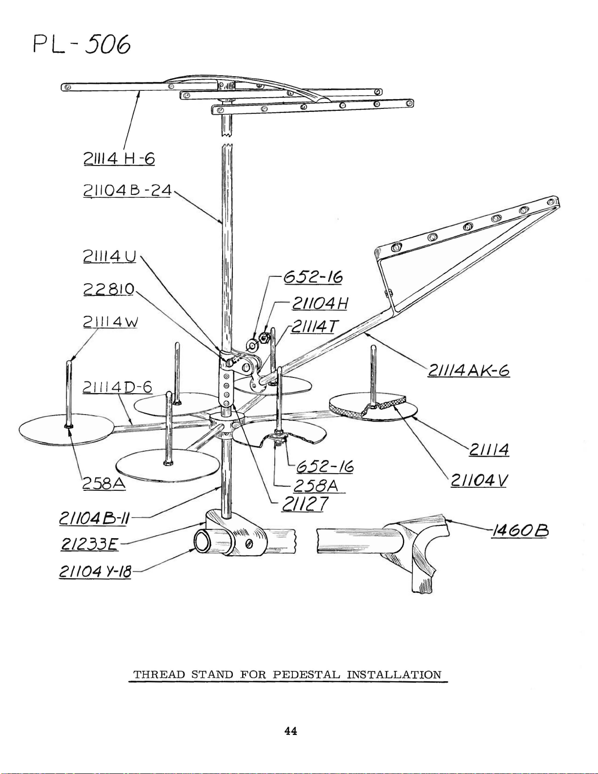
PL-
506
21114
21104 B
21114W
H -6
-24
21114AK-G
21104
Y-1~
THREAD
STAND
FOR
652-16
258A
21127
PEDESTAL
44
21114
21104V
14608
INSTALLATION

!flo.
01
"F"TAf'
£JR1t.l(251)
i -IB(H-3) THf).
2fl0t.ES
IN
PE/JESTAL
BASE
c::=J c::=J
c:=:Jc:J
c=Jc=J
c=Jc=J
CJCJ
.H
7 TAP f)R/LL (201)
j
-t?o
(H-3)
PL-511
Th'/J .
.lJRIL/. I TAP HOLE THIS
OF
TREA.lJLE;
OF /477
AS
Sh'OWN
S/LJE
/N
J//EW A
THIS
PLANOGRAPII
FOR
CONI/E/?T/NG
TO
(JSE
29480/JZ
,11£CIIANISM
J/I£W
KIT.
A
SHOWS
Til£
NOOK
TR£.4/JLE
THE
MET#O.O
PE/JESTAL
/NT£1?-LOCK

Part
No.
18
••••••••••••
20
••••••••••••
CL21
.••
• • • • • • • • • 21
22
KH·········21,35
25 s
.........
28
••••••••••••
28 A
••••••••••
28 c
..........
G
••
36
50-533
50-537
51-15
51-120
WR56
WR57
WR62
WR64
WR69
69 H
73
73
77
86
87 A
J87
87
88
88
89
90
93
93
94
97 A ••••••••••
98
107
108
109
118
150
255
258
258 A
269
318
421
531
538
604
605 A
650 X
651-16
651 B
652-16
652 B
652
652
660-161
660-202
660-207
660-215
660
660-219
660-220
•• •• • •••
Blk
Blk
Blk
Blk
••••• • •• • •••
••••••••••••
••••••••••••
••••••••••••
••••••••••••
••••••••••
A
••••••••••
c
..........
••••••••••••
••••••••••••
••••••••••
J
••••••••••
u
..........
••••••••••••
B
••••••••••
••••••••••••
••••••••••••
••••••••••••
A
••••••••••
••••••••••••
A
••••••••••
••••••••••••
•••••••••••
••••••••••••
GAS
••••••••••••
............
••••••••••••
••••••••••
••••••••••••
••••••••••••
D-28
••••••••••••
••••••••••••
............
••••••••••
••••••••••
.........
••••••••••
•••••••••
..........
C-9
K-24
- 219 D
p
NOTE: Only
the
····21
••••
•••••
••••
••••••••
.......
••••••••
•••••••
........
••••••••
••••••••
........
••••••
.•••••
••••••••
the
listings
Page
No.
29,
31,
33
·19
27
27
21
33
21
35
19
41
41
41
41
41
21
21
21,
35
23,
31,
25
35
35
29
33
25
23
21,
23
21
21
25,37
29,
33
35
25
·25
25
27
37
25
31
25,
33,41
29,
31,
27
43
23,
35
35
33
33
43
41,43
19
41
43
33
35
19
2~3~35
2~29,31
33
33
23,33
23,
35
basic
part
on
pages
NUMERICAL
Part
No.
33
33
33
660-221
660-254
660-261
660-272
660-275
660-302
660-311
660-457
664 F
.•••••••
666-96
666-128
667 D
••••••••••
699
s
..........
1096B
..........
1347 A ..........
1421
••••••••••••
1421 A ••••••••••
4761
••••••••••••
6042
A.,
9271
••••••••••••
12934 A ••••••••••
14087
••••••••••••
15037 A ..........
21101 R ..........
21104 B ..........
21104 H ••••••••••
21104
v
21104 y ..........
21114
21114 A ..........
21114 D •• , ••••• , .41
21114 H ••••••••••
21114 T ..........
21114
21114
21114
21127
21201
21207 A ••••••••••
21209 D ••••••
21209 E •••••••••
21209 F ••••••••••
21209 G ••••••••••
21209 H .........
21209
21209 K ..........
21209 L ••••••••••
21225 F •••••••• , .41
21227
21227
21227
21221
21227
21227
21227
21227
21227
21227
21227
21227
21227
21233 E •••••••••
21233 K •••••••••
21261 M ..........
numbers
..........
••••••••••••
u
..........
w
..........
AK
••••••••••••
••••••••••••
J
••••••••••
AR,
BU
BV
ca
CH.,
CJ
CK
CM
CN
cs
CT
cu
cv
are
indicated.
••••••••
c
......
••••••••
••••••••
••••••••
••••••••
........
••••••••
•••••••••
••••••••
••••••••
........
,.,
•••••• , ,43
.........
........
.........
.......
.........
.........
......
.......
........
........
.........
........
shown
in
• •
,43
,43
,43
,41
.,43
.,43
,43
,43
,41
,43
,43
the
Page
33
25,
27
41
19
19
33
43
27
19,
19
35
41
33
43
43
43
33
23,
43
21,
43
33
41
41
41
41
43
41
41
41
41
41
41
41
41
41
41
43
43
43
43
43
41
43
43
43
43
43
19,
INDEX
No.
43
21
27,31
33
41
index.
OF
PARTS
Part
No.
21371
UE
21388 y ..........
21388
21388
21388 A Y
21661
21661 D
21662 y ..........
21662
21662
21663
21663 E .........
21665
21705
21756
22504 c
22513
22516 A ..........
22517
22519
22524
22528
22539 M .........
22539 N ..........
22539 T
22560A
22562 A •••••••••
22564
22564 B ..........
22564 D ••••••••••
22565 A .........
22569 B ..........
22569
22570 A •••••••••
22571 A
22571 B
22572 B .........
22574
22580
22585
22585 A ••••••••••
22585
22587 B ..........
22587 E ••••••••••
22593
22596 B ..........
22596 D ••••••••••
22635
22640 M •••••••••
22650
22651
22652 A ••••••••••
22652 F ..........
22653 B ••••••••••
22653 E .........
22703 A ••••••••••
22711
22716 A ..........
22729
22729
22729 D ••••••••••
22731
22733 B ••••••••••
For
.........
AW
.........
AX
••••••••
.........
............
••••••••••
z
.........
AA
.........
••••••••••••
............
............
G
.........
..........
............
............
F
..........
••••••••••••
............
..........
..........
•••••••••••••
c
.........
••••••••••
.........
•••••••••••••
••••••••••••
••••••••••••
c
.........
............
............
AE
........
CD
•••••••••
••••••••••••
.•••••••••••
c
..........
••••••••••••
various
gauges,
Page
No.
19
41
41
,41
43
43
43
43
,43
43
43
,43
43
19
,23
29
27
21
25
23
27
29
,21
35
21
27,35
,23,
25,
35,37
23
21
33
,37
21
,19
,29
19,
35
,23
,33
19
23
33
23,
33
,25,
35
23
23, 29,
21
23
21,
35
43
,43
,19,
23
41
33
19
27
,35
43
21,
31
35
23
31,
33
33
37
21
capacities,
Part
No.
22738
22738 B •••••
22738 G •••••
22738 H .••••
22747
22759A
22766
22767 A •••••
22768 B .....
22777 B .....
22791 D .....
22791 E .••••
22795 B •••••
22797
22798
22799 B •••••
22799 N •••••
22801
22807
22810
22829
22839
22839 D •••••
22845 M •••••
22849
22881A
22882 A .....
33,
22894
22894 E •••••
22894
22894 J ••.••.
22894 K •••••
22894
22894
22894 X •••••
23441
28604 R •••••
29101
29103 T •••••
29478
29478
29478
29478
29478
31
29478
29480
33174 B •••••
35746 A •••••
35751 G •••••
35760 D •••••
35761 D •••••
35763
35763 F •••••
35763 G •••••
35766 B •••••
35767
35781 D •••••
35792
35792
35792 E •••••
35792 H •••••
35792 K •••••
35792 M •••••
etc.
•••••••
•••••••
•••••
.••••••
•••••••
•••••••
•••••••
•••••••
.......
•••••..
.......
.......
•••••
c
.....
H
•••••
v
.....
w
.•...
p
••••.
J
••••••
cs
....
CT
••••
cu
....
cz
....
DM
•••.
DR
•••
• 33
CK
•••
,19
•••••••
•••••••
•••••••
c
.....
available,
Page
No.
43
37
37
27
31, 33
27
23,
35
33
21
27
21
35
33
23
35
21
33
23,
35
43
41
21
21
25
29
35
27
19
19
23
23
23,
25
23
19
23,
29,
31,
35
19,2~33
41
43
23,
31
2~29
29
31
33
35
31
29
31
33
21
21
23
23
23
31
27
21
25
25
25
25
25
25
refer
to
46
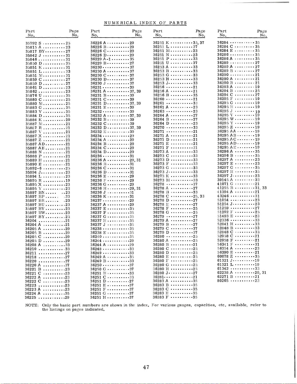
Pa
rt
No
.
35
792
s ...
35815 A •••••.•.••
35
817
35842 J ••••••••••
846
35
3
8 50 0
851
35
35851 L ......
851
35
859
35
358 59 D
35
861 D •••
35
862
35
876
35880
35
880 M ••••••••••
883 G ..........
35
35
883
35
884 D ••••••••••
884 K ..........
35
35
887 1 .••.••.•. • 21
35
87R
887
35
35887 X ..
35887
35
887
35887
888 N ........
35
35888
35
889 H •••••••••
890 E .•.•••••
35
35
892-6 ..........
35894 J ••••••
35
894 L .......... 23
35895 H ..........
3895X
35895
35897
897 BP..
35
35
897
35897
35
897
35
897
35
897
36204
36204
3620
5 A
3620
5 B
3620
5 c .
3620
5 D
36208
36210
36211
36218
36220
36220A
36221 B ..........
36221
36222 A ••••••••••
36222
36223
36223
36224 A •••••.••
36225
NOTE: Only
.......
BY
•••••••••
• . • •
••••••••
.•••••••••
I<
..........
I
c
............
u
c
v
y
z
Ao
AE
p
y
BN.....
BR...... .
BU
BV
BW
BY
........
A .
..
..... • ....
..........
••••
. • • . • •
• . ••••.
..........
..........
..........
•••.••••••
.. ..
......
.... ....
..........
.........
••••.••••
..........
• .
••••••••••
..........
.. ..
.........
••••••.••
.........
.........
..
•••••••••
••••••••••
.••••
• .
.........
..........
A .
•••••.•••
•••.•••••••
••••••••••••
••••••••••
•••••••.•.
••••••••
c .
.........
c ..........
•••••••.••••
A • • .
•••••••
.•••••••••
the basic part
e
listings
th
..
..
. •
•••
..2
. . 21
•••
• •
. • 37
• • 37
• •
• •
Pa
2
23
27
31
31
35
31
33
31
27
27
23
23
35
25
25
35
35
35
29
21
21
21
21
21
21
21
21
• 21
21
2
23
19
23
23
3
. 23
23
23
23
23
23
21
29
29
29
29
33
. 33
27
27
23
23
23
23
23
23
35
29
on pag
ge
No.
numbers are
es
NUMERICAL
Pa
rt
No.
36226 A·· ··
36226
36226
36226
36229
36229
36230············37
36230
362
30 c
36230
36230
36231
36231 A ••• •••••••
36231
36231
36231
36231
36232·····
36232
36232
36232
36232 D ••
36232
36234
36234 A·····
36234
36234
36234 D ..........
36236············31
36236
36236
36236
6236
3
36236
36236 F ..........
6236 G .. ••·
3
362
36 H • · •
36236
3
6236 K ......
36237
3
6237 A ..........
36237
3
6237 F •••
3
6237 G ..........
36237 H ..
36237
3
6238
36238 E
3624 0
36244 .
3
6244
36248
362
49 ••..
3
6249A
3
6249 B ..
3
6250
36250 G • • · · • • • • · · 37
3
6251 B ......
3
6251
362 51 D • • •
3
6251 E ....
36251
3
6251 G ........
3
6251 H ••
••
B ·
........
c ..........
0 ·
·········29
A-1
........
B • • • • • • • • • • 27
A ·
·········
.........
D··········37
J
..........
····
· ·
······39
B • • • • • • • • • • 39
c
..........
o ...
......
E • • •
•. • ••
· ·
A·· .......
13
c
E ·
•••••••.••• ·29
13 ........
c
A·
13
c
D • • • • •
E • • •
J .
••••••••••. ·29
E • •
J ....
••••••••••••
••••••.••••
A ·
••.•••••
···
c
F • • •
·····39
• .
••••••.•
..........
· •
•••• • ·37
.. • .....
····
..........
........
•••••••••
..........
••
·• • •• • ·29
••
••
• • • • •
....
....
.... • .. ·35
••••••
....... ·35
....
......
•••.•••.•• ·29
·········
••••••• ·33
···
· · ·····35
........
· · · · · · · · · 37
.......
•••.••
......
•• • ••••
• • ••. • • . 37
shown
mdicated.
••••
29
·29
29
. 37
37
39
·37
• • 39
·37
·39
·29
..
29
29
29
·29,
·31
31
· •
·31
29
..
· 29
29,
· 31
....
31
29
· 35
35
oo35
35
....
35
· 35
29
• • . ·33
33
....
33
..
· 33
·27
37
37
..
37
in the
INDEX
Pa
ge
No.
35
37
37, 39
, 39
, 39
39
39
, 39
31
31
index. F or
O F
PARTS
Part
No,
362
51 K
362
36251
362 51
362
362 51 u
362 5
36253 B ·
362
36253 H
36253 J
362
36256 A ·
362 56
362 60
36261 ••.
36261 A ··········2
36263
36264
36264
36264
36270 ············3
36271
3
6271
36271 D ·········
36271 E
3
6271 F ··········
3
6273 A ·········
3
627
3
627
36273
36273 G ········
3627
3627
36273 Ill · ···· · · ·
3
6278
3
6278
3
6278
36278
36278
3627
3
6278 F ··········2
36278 G ······
36279 ············27
36279 A ··········2
3
6279 B •••·•••
36279 c ··········37
36279 D ··········
362 80 ••.
3
6280
3
6280 B .. ..
3
6280 c ··········2
36280 D ···
3
6280 E ·········
3
6280 F •••
3
6280 G ..........
362
36280
3
6281·
3628
3
6283 B ··········3
362
3
6283 E ··········3
36283 F ········
··········3~37
51 L
..........
I\(
......
N.
• •
....
•••..••
......
51 p
.........
3A
··········33
........
53 G ..
56
80 H ··········2
83 c ··········35
....
..........
•••.•••.•••
...........
........
13
........
.......
"
A ·
B · • •
D • •
••••• ·······21
A········
3 c
3 D
F ·
3 J ·
3 K
· ····
A · ·
B "
c ..
D · · · ·
8 E
A • • • • • • · • • ·2.
J.
••••••••••
3 A •
....
···
· ·
00
"""
·········27
·······27
••
·•
··········21
··········3
··········3
••••·•• ··33
········
··········33
·····
········27
"""
.......
······27
••••••••••27
·········2
......
· ·
·····2
• • •
····
······27
.........
..
.. ..
····3
· • .
· ·
··
••••2
..
oo35
oo2 3
· · 21
··
·
··3
· · 37
..
··2
. ·21
··35
var·ous gauges,
37
23
23
33
·37
·33
33
33
33
·2
·21
·21
·23
· 21
21
· 33
33
·33
33
·2
·27
37
21
· 25
25
35
cap
Pa
No.
1
3
3
3
3
3
3
5, 33
5
5
7
5
5
5
5
ge
acities,
Part
No.
3
6284
•••.•••..
36284
c
....
36284 E ....
36286 •.•
36286
36289
36289
362
89
36290
36290 A •• · ••
36290 B ....
36293 A ........
36294 B ........
3629
4 c
3629
5 F ...
3629
5 G
3629
5 H · • • · · · • •
3629
5 J
3629
5 "
3629
5 w .
3629
5 y
3629
5 z
3629 5 AA .
3629
5 A
36295 AC.
36295 AD····
3
629
5 AE
36296 A .........
36296
3
6297 A .........
36297 E ........
36297 G .........
36297
36297
3914
5 A • • • • • · • • · 33
41071
41255
4 1394 A
4
3246
51054
512
54 J
51259
5
1292 F .........
51
493 E ....
52336
5
2841 H ......
528
48 B ........ ·33
5
2848
52958 c ·
52958 F
5634 1 F ••• ·
56354 A
5
6390 E .....
60078 z ·····
613
21 J
61 321 L
613
42
622
38
62271
80265 .•
etc. ava
.....
....
••••..
A • · • • • · • • • 35
. •
.•...•.••
A • • • • . • · • •
13
......
• •
•••..••.•
• ·
.........
......
.... • ....
.........
•••.•••. ·19
......
..
.......
........
.......
13
. • . • · • .
• •
••
........
B ·
....
11·
········3
J .
.........
G ·
···
· ····
13
......... 31 33
........
.. ..
....
···········23
.........
•••••••••
.... ·23
•••••••••. ·33
c . ·
····
········
······ ···21
·····31
·········2
..........
• ····
···········3
A • • • • • • • • ·29, 31
B ·
........
•••••••••
ilable, ref
. • 35
• 35
.•
...
• • · •
.. • 21
·
• 25
·19
..
·19
·19
· . · 19
.. · ·19
....
·23
·21
..
· 3 1
·23
. •
.. ·33
···
..
..
··
··3
····1
35
35
27
27
27
21
21
19
27
19
19
19
19
19
19
19
35
3
23
35
23
21
27
2
3
21
21
19
21
23
er
Pa
5
9
ge
No.
5
,
3
3
to
47

WORLD'S
FINE
ST
QU
ALITY
*
INDUSTRIAL
SEWING
MACHINES
UNION
SPECIAL
maintains sales
facilities throughout the world. These offices wi
aid
you
in
the selection of the right sewing
equipment for your particular
Special representatives
trained
tory
promptly
there
tion,
and
are
and
efficiently.
is
a Union Special Representative
serve you. Check with
ATLANTA,
BOSTON,
CHICAGO,
DALLAS,
LOS ANGELES, CAL.
NEW
PHILADELPHIA,
GA.
MASS.
TEXAS
YORK,
ILL.
N.
Y.
PA.
and
able
him
operation.
service men
to serve your needs
Whatever
today.
MONTREAL, CANADA
TORONTO,
BRUSSELS,
LEICESTER,
LONDON,
PARIS,
STUTTGART, GERMANY
and
service
Union
are
your loca-
CANADA
BELGIUM
ENGLAND
ENGLAND
FRANCE
ll
fac-
to
Representatives
industrial
and
cities
distributors
throughout
In
the
all
important
world.
CORPORATION
400
N.
FRANKLIN
ST.,
CHICAGO,
ILL.
60610
 Loading...