

Page 1
Feed-off-the-arm, 4-needle “Flatseamer” for
Top and Bottom Coverstitch
Minute-quantity
®
36200 Series
lubrication
ENGINEER’S MANUAL
40040898
No.E373-00
Page 2

Introduction
This Engineer’s Manual is written for the technical personnel who are responsible for the service and maintenance of the machine.
The maintenance services to be done on this sewing machine should be based on this manual.
This manual gives the "Standard Adjustment" on the former section under which the most basic adjustment
value is described and on the latter section the "Results of Improper Adjustment" under which stitching errors
and troubles arising from mechanical failures and "How To Adjust" are described.
Page 3

CONTENTS
1. Specifications ........................................................................................................ 1
2. List of models ........................................................................................................ 2
3. Model numbering system............................................................................ 3
4. Configuration.................................................................................................
(1) Head names .............................................................................................................................. 4
(2) Names of presser body ........................................................................................................... 5
5. Needles ......................................................................................................... 6
(1) Needle types ............................................................................................................................. 6
(2) Features of needles ................................................................................................................. 6
(3) Needle applications ................................................................................................................. 6
6. How to conduct threading........................................................................... 7
7. Standard adjustment .............................................................................................. 8
(1) Presser removal work...................................................................................................... 8
Adjusting the height of the needle bar......................................................................... 10
(2)
Adjustment of needle array ........................................................................................... 12
(3)
(4)
Right and left needle entry position adjustments ....................................................... 14
Looper adjustment ......................................................................................................... 16
(5)
1) Returning amount of the looper .........................................................................................................16
2) Adjustment of a clearance between looper and needle .....................................................................16
(6) Adjustment of looper and needle bar timing ..................................................................... 18
(7) Adjustment of looper movement......................................................................................... 20
(8) Adjustment of looper movement locus .............................................................................. 22
(9) Adjustment of the feed dog ................................................................................................. 24
(10)Adjustment of needle holder ............................................................................................... 26
1) Adjustment of rear needle holder.......................................................................................................26
2) Adjustment of forward movement needle holder ...............................................................................26
(11)Adjustment of feed mechanisms ........................................................................................ 28
1) Stitch length adjustment ....................................................................................................................28
2) Adjustment of differential feed amount ..............................................................................................28
(12)Adjustment of presser main body mounting ..................................................................... 30
(13)Adjustment of the presser main body proper .................................................................... 32
1) Adjustment of presser lifter connecting lever .....................................................................................32
2) Adjustment of presser lifting strap plunger ........................................................................................32
3) Adjustment of minute presser lifting...................................................................................................32
(14)Adjustment of top fancy looper and fancy thread carrier................................................. 34
1) Stroke position adjustment of drive sleeve ........................................................................................34
2) Amount of fancy thread carrier injection ............................................................................................34
3) Leftmost point of top fancy looper......................................................................................................36
4) Clearance developed at the time of crossing between the fancy thread carrier and
the tip of the top fancy looper ............................................................................................................36
5) Rightmost point of top fancy looper ...................................................................................................36
6) Height of top fancy looper ..................................................................................................................36
(15)Adjustment of top fancy cam and bobbin thread cam ...................................................... 38
1) Adjustment of top fancy cam .............................................................................................................38
2) Adjustment of bobbin thread cam ......................................................................................................38
4
Page 4

(16) Knife adjustment .................................................................................................................. 40
1) Lower knife adjustment ......................................................................................................................40
2) Upper knife adjustment ......................................................................................................................40
3) Pressure adjustment of upper knife ...................................................................................................40
(17) Adjustment of upper knife drive lever................................................................................ 42
(18) Adjustment of needle thread path ...................................................................................... 44
1) Adjustment of needle thread guide bar ..............................................................................................44
2) Adjustment of needle holder adjusting pin .........................................................................................44
3) Adjustment of needle thread presser spring ......................................................................................44
(19) Adjustment of tension disk rise and protection cover ..................................................... 46
1) Adjustment of tension disk rise ..........................................................................................................46
2) Adjustment of protection cover ..........................................................................................................46
(20) Adjustment of lapformer...................................................................................................... 48
8. Lubrication ........................................................................................................... 50
9. List of rear spring ................................................................................................ 51
(1) One side trim......................................................................................................................... 51
(2) Both side trim........................................................................................................................ 52
(3) Taping .................................................................................................................................... 53
(4) Step gauge ............................................................................................................................ 53
(5) Butted seam .......................................................................................................................... 53
10. Types of feed dogs.............................................................................................. 54
11. Maintenance......................................................................................................... 55
(1) Spare parts ............................................................................................................................. 55
12.Troubles and corrective measures............................................................56
13.
Table drawing ..............................................................................................68
(1) Auxiliary drive table.............................................................................................................. 68
(2) Auxiliary drive sub-table...................................................................................................... 69
Page 5
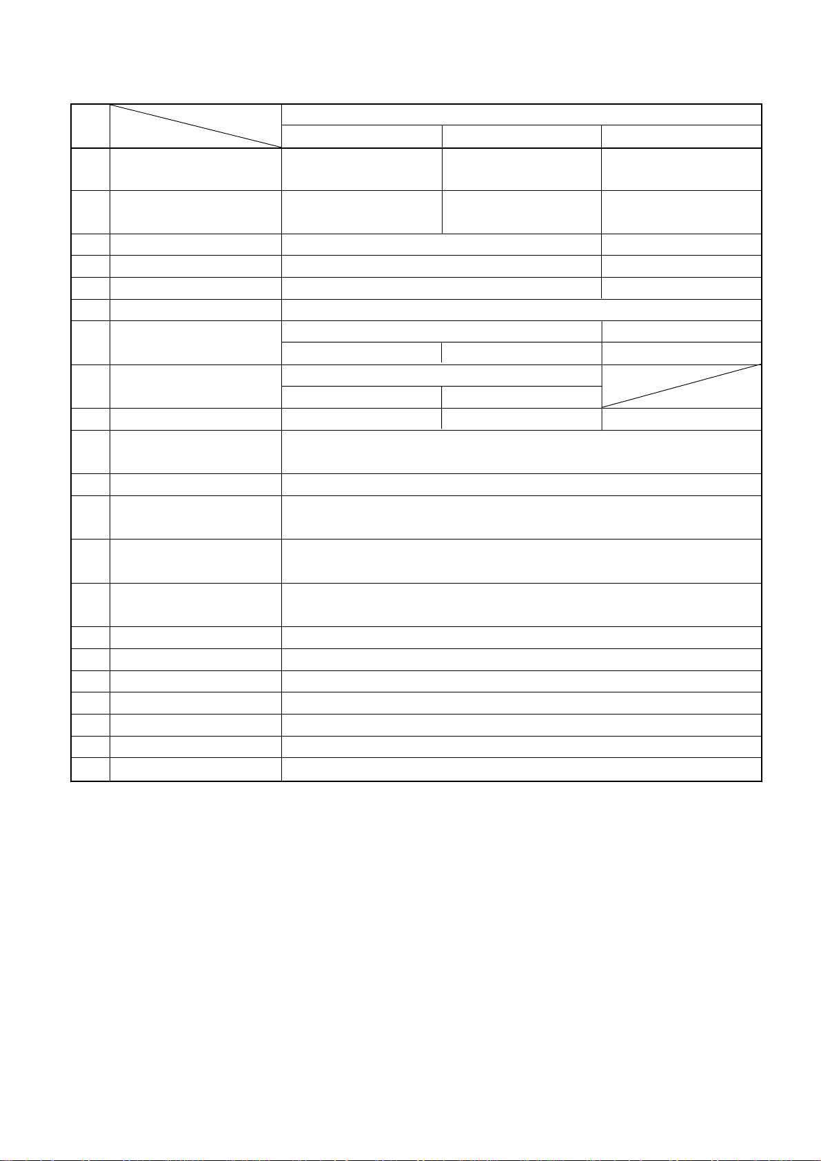
1. Specifications
No. Application
Item
1 Application Intended for taping
2 Sewing type
3 Max. sewing speed (normal) 4,200rpm (normal sewing speed: 3,200rpm) 4,200rpm (normal: 2,500rpm)
4 Stitch length 1.6 to 2.5mm (Standard 2.1mm)
5 Needle gauge 5.2mm, 6.0mm 6.0mm
6 Needle bar stroke 30mm
Needles to be used
7
(Standard needle count)
Retainer needles to be used
8
(Standard needle count)
9 No. of threads used 6 pcs. 5 pcs. 7 pcs.
10 Feed control system
11 Lubrication
12 Quantity of oil storage
13 Lubricating oil
14 Installation system
15 Lifting amount of presser One side trim type 8.0mm, both side trim type 6.0mm
16 Minute presser lifting Provided as standard
17 Needle thread silicone tank Provided as standard
18 External dimensions Height 31.5mm x Width 25.5mm x Depth 42.5mm
19 Weight of head 22kg
20 Working temperature/humidity Temperature : 5°C to 35°C, Humidity : 35% to 85% (no condensation)
21 Supply voltage/frequency Rated voltage ±10% 50 / 60Hz
Model name
36200L/36200U 36200T 36200L220
General light-weight -
medium-weight materials
4-needle both side trim
fancy sewing
UY118GKS065 to 080 (#9 to #12) UY116GKS065
* (Standard 70/ #10) (Standard 80/ #12) (Standard 65/ #9)
36211-060 to 075
* (Standard 65/ #9) (Standard 75/ #11)
Main feed ----- Slide type stitch pitch control system
Differential feed ------------Lever control system
Rotary pump type auto lubrication (minute-quantity lubrication to needle bar and looper sections)
Union Special Specification 175 (equivalent to ISO VG22) or
Table and Aux. Drive mounting system
4-needle one side trim
fancy sewing
Front oil storage: 70ml to 80ml
Rear oil storage: 60ml to 70ml
JUKI Oil SUP2000 – 1L
Pedestal mounting system
For light-weight (swimsuits)
materials
5-needle both side trim
fancy sewing
1.6 to 1.8mm (standard 1.6mm)
* For standard usage in Japan, the needle count is [Standard 65/#9]. The needle count for retainer needles is [Standard 60/
#8].
– 1 –
Page 6
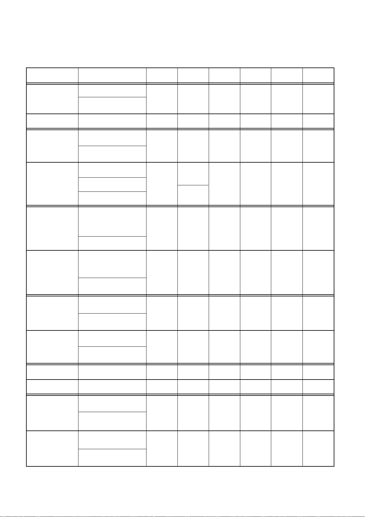
2. List of models
The standard models are the lapseamers with 4 needles and 6 threads for vertical fancy stitch.
According to the model names, they are classified into specifications for the specific gauges, step gauges, taping,
and multi-purpose.
Model name Application Top fancy Knife Lapformer
General knit goods
36200L100-52 4 1 6 With
Light- and medium-weight
materials
Number of
needle
Retainer
needle
Number of
threads
One side trim
Without
36200L100-60 General knit goods 4 1 6 With
General knit goods
36200L200-52 4 1 6 With
36200L200-60 4 6 With
36200L202-52 boxer's briefs, etc.) 4 1 6 With
36200L202-60 boxer's briefs, etc.) 4 1 6 With
Light- and medium-weight
materials
General knit goods
1
Light- and medium-weight
materials
Swimsuits 0
Specific gauges
(Thigh patch-up for
Medium-weight materials
Specific gauges
(Thigh patch-up for
Medium-weight materials
One side trim
Both side trim
Both side trim
Both side trim
Both side trim
Without
With
With
With
With
1.27mm step gauges
36200L210-52 4 1 6 With
36200L210-60 4 1 6 With
36200T300-52 Fly taping 4 1 5 Without
36200T300-60 Fly taping 4 1 5 Without
36200U300-52 4 1 6 With
36200U300-60 4 1 6 With
Medium- and heavy-
weight materials
1.27mm step gauges
Medium- and heavy-
weight materials
Multi-purpose
Light- and medium-weight
materials
Multi-purpose
Light- and medium-weight
materials
Both side trim
Both side trim
One side trim
One side trim
Combined use Combined use
Combined use Combined use
With
With
Without
Without
(Caution) The list shows the models exclusive for 4 needles. It does not include the models for 5 needles.
– 2 –
Page 7
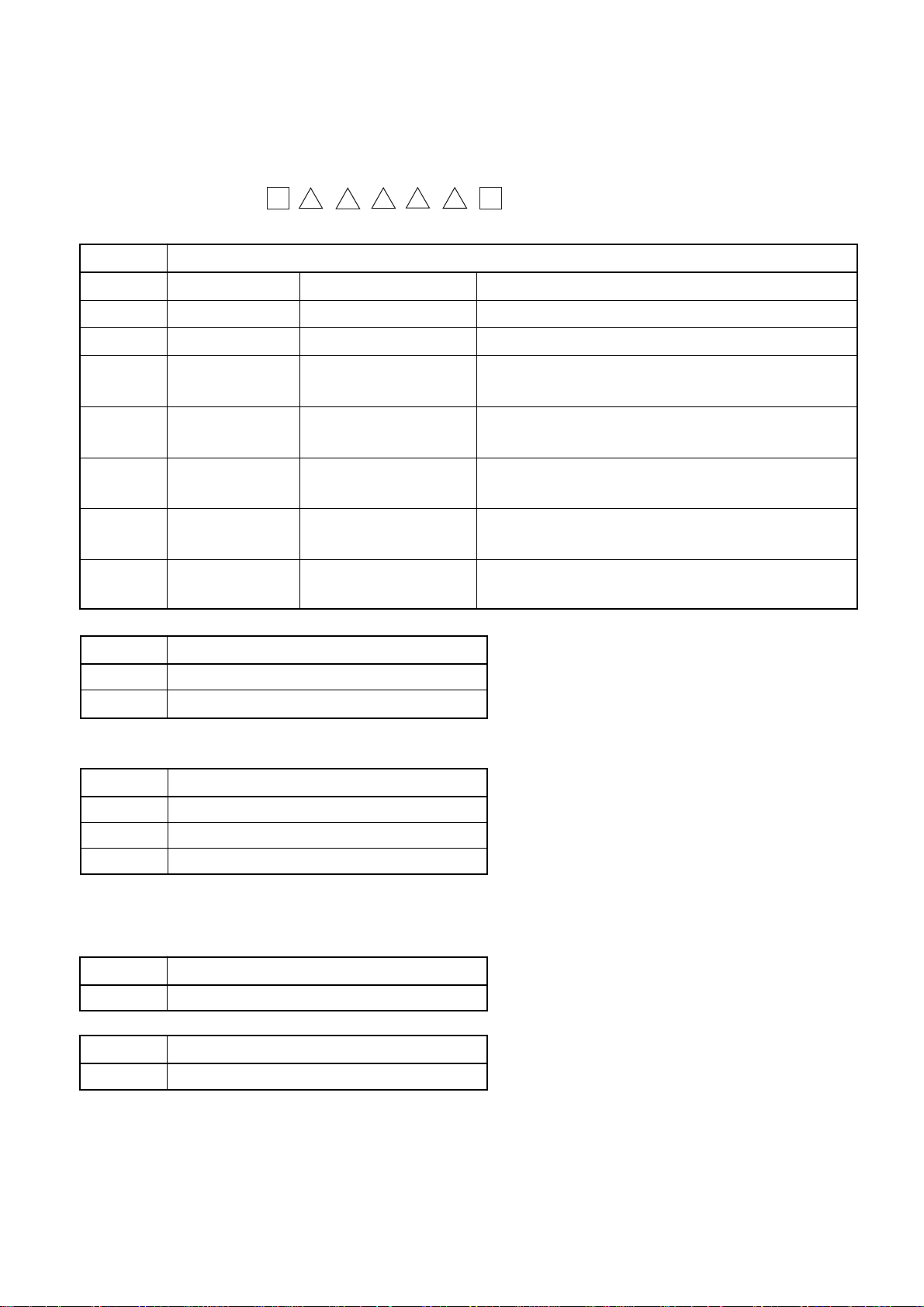
3. Model numbering system
Name: Feed-off-the-arm 4-needle “Flatseamer” for Top and Bottom Coverstitch
123456789101112131415
36200 —AA
6 to 9 Head specifications
Code Specifications Cloth cutting Applications
L100 Lapseam One side trim With edge guide spreader
L200 Lapseam Both side trim With lapformer spreader
L202 Lapseam Both side trim Specific both side trim gauge lapformer
With spreader
L210 Lapseam Both side trim
L220 Lapseam Both side trim Specific 5-needle presser, lapformer
T300 Taping Combined use for one side Without spreader, tape reel
and both side trim With tape folder
U300 Multi-purpose Multi-purpose specifications
10 to 11 Needle gauge
52 5.2mm
60 6.0mm
* Head spec. L220 applicable to 60 (6.0mm) only
12 Region
J Japan
N North America, Europe
S Asia
Combined use for one side
and both side trim
Both side trim 1.27mm, step presser, throat plate, feed dog
With lapformer spreader
With spreader (for swimsuits)
* Head spec. L100 only, Impossible to select J
J (for Japan) of L100 covered by S
14 Place pf destonation
A Standard
15 Accessories type
A Standard
– 3 –
Page 8
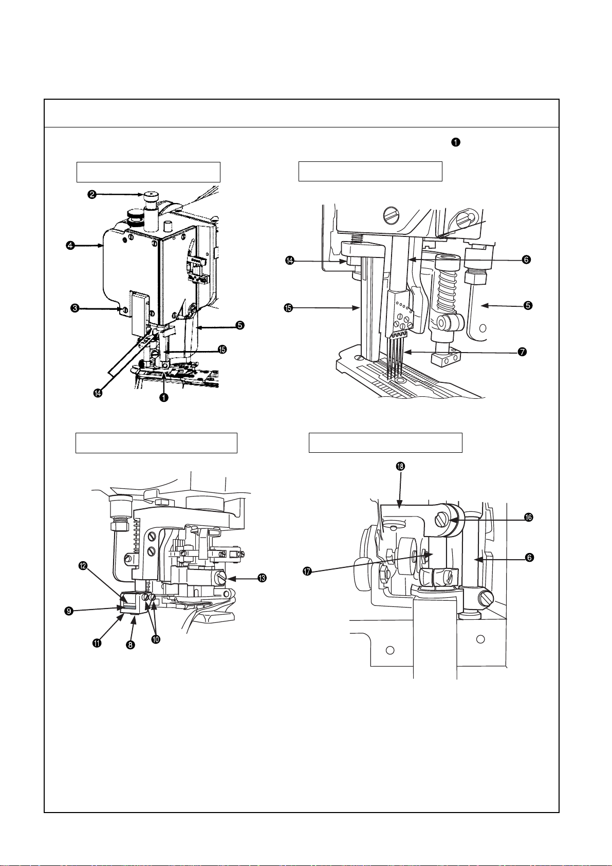
4. Configuration
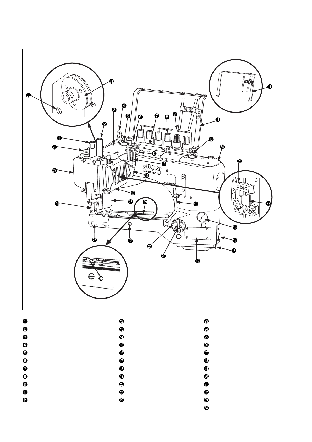
(1) Head names
Presser pressure stroke adjusting screw Frame needle thread path Looper cover
Needle bar guard Needle thread guide bar Presser
Rear top cover Thread path frame Face cover
Lift lever Looper thread guide Minute presser lifting
Oil circulator check window (rear) Stitch length control window screw Swing guard
Oil gauge (rear) Oil gauge (front) Protection cover
Needle thread silicone unit Oil drain screw (front) Lapformer
Thread tension knob Cylinder side cover Oil drain screw (rear)
Thread guide Differential adjusting lever Pulley
Oil circulator check window (front) Scale plate feed Needle thread rocking guide
Threading guard (Assy) Feed dog eccentric pin Needle thread holder adjusting pin
– 4 –
Front top cover
Page 9
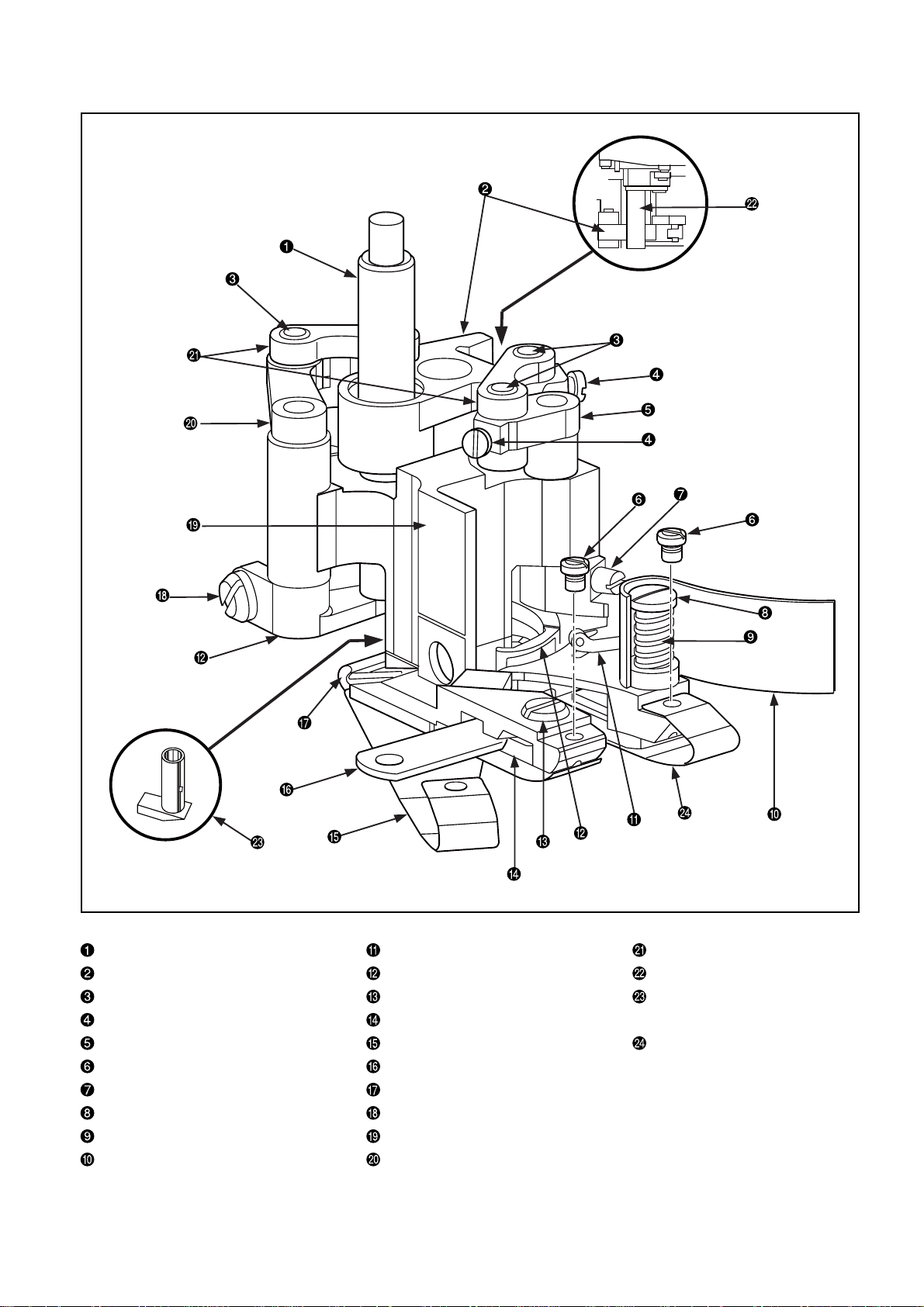
(2) Names of presser body
Presser bar Fancy thread carrier Drive lever link
Drive link Top fancy looper Drive sleeve
Link pin Lower knife clamp setscrew Minor presser (Minor presser
Link pin setscrew Lower knife clamp for stepped materials)
Drive lever shaft (carrier) Rear spring, left Rear spring, right
Rear spring setscrew Lower knife
Fancy thread carrier setscrew Rear spring hanger wire
Thread chips guard setscrew Fancy looper setscrew
Spring Presser main body
Thread chips guard Drive lever shaft (looper)
– 5 –
Page 10
5. Needles
(1) Needle types
UNION standard accessory needle GROZ-BECKERT/UY118GKS 070/#10
No. Needle symbol Thread groove Scoop Strength Thread available for sewing
1
2
3
4
UY118GKS With Weak
UY118GAS Without Strong Spun thread
UY118GBS Front only With Weak Wooly thread
36211
Presence of front Spun thread, wooly thread,
and rea Tetoron thread, cotton thread
Presence of front
and rear
(2) Features of needles
No. Features
The front and rear sides of a needle have thread grooves. It is somewhat more difficult to obtain an
adequate tension for the needle thread, compared with the 118GAS.
1
Since there is a scoop behind the needle, the effect of prevention against stitch skipping can be
expected even for a thread that is inefficient in making loops.
There are thread grooves provided to both the front and rear sides of a needle. The needle thread
tension tends to be increased.
Since no scoop is provided to rear side of the needle, needle bend is minimum at the time of
2
needle entry into the materials. This type of needle is suitable for the products of heavy-weight
materials or those that involve thick sections in materials. (General knit goods, etc.)
Since no scoop is provided, it is not suitable for applications to wooly or Tetoron threads.
Since no thread grooves are provided to the rear side of a needle, the needle thread tension tends to
be decreased. Since there is no thread groove and a scoop is provided to the rear side of the needle,
3
the needle thread can produce loops easily and therefore this type of needle is suitable for applications to wooly threads or the like.
4
If a retainer needle (sacrifice needle) is used, softer switches can be obtained.
(3) Needle applications
No. Applications
1
Used for the products of knit goods and swimsuits.
2
Used for general knit products.
3
Used for ladies’ shorts, girdles, etc., made of stretchy textiles.
4
Used for general products of knit products.
(Caution) Standard needles used in Japan are of UY118GKS•GAS, 065 (#9).
– 6 –
Page 11
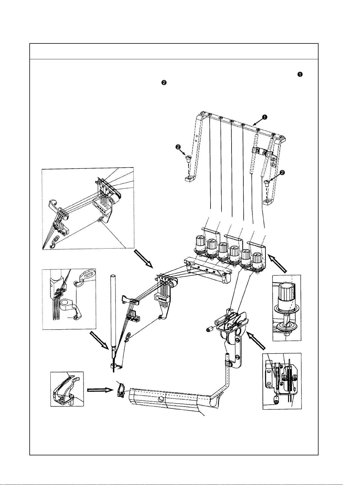
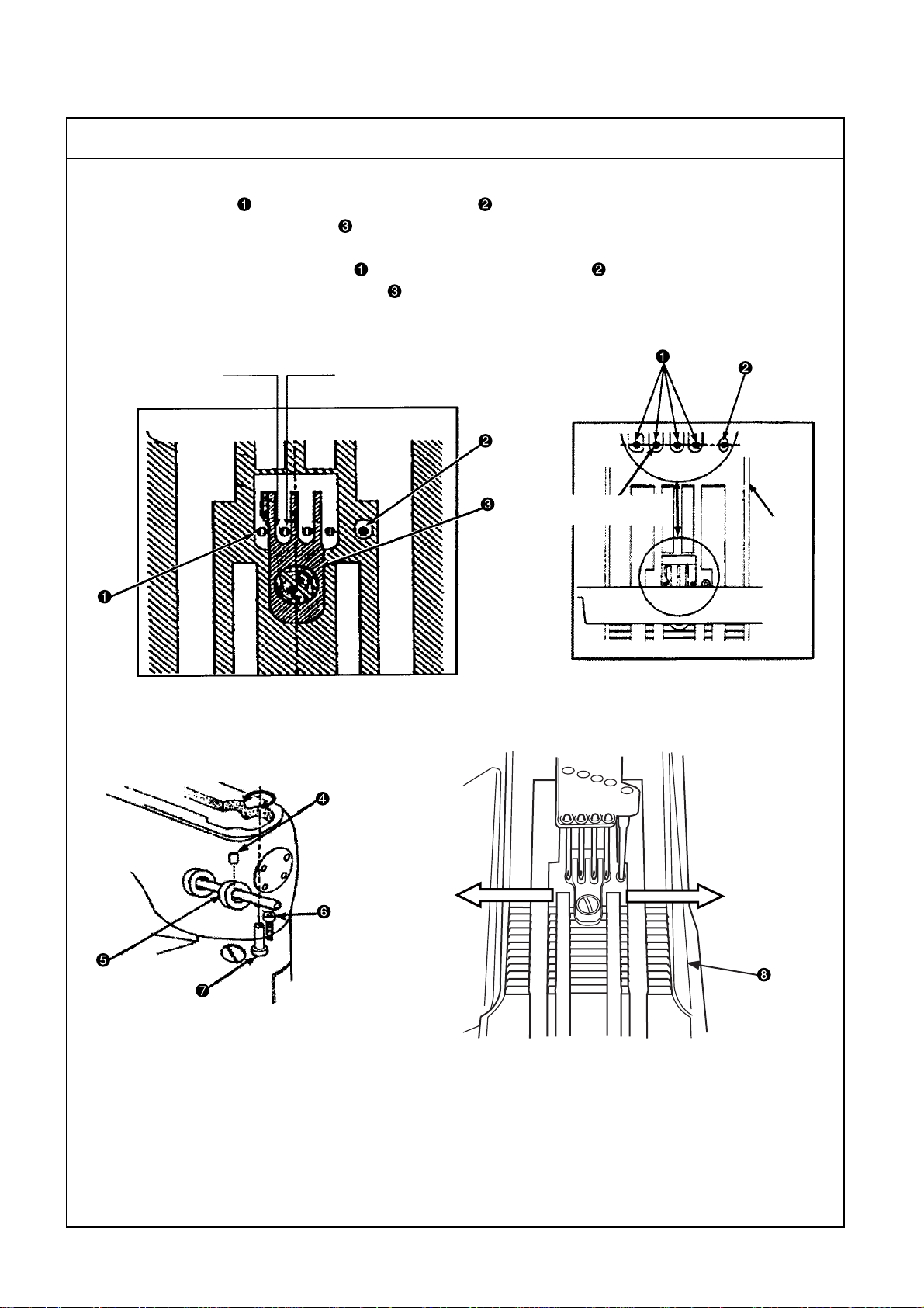
6. How to conduct threading
How to make threading for the needle threads and the top and bottom fancy threads
Threading illustration and threading guard setup
1. When you want to use the flatseamer machine head, you have to mount the threading guard (Assy) .
It can be mounted by means of two setscrews (2 pcs.).
2. 1 to 4 correspond to the needle thread, 5 to the top fancy thread, and 6 to the bottom fancy thread.
Make threading according to the threading illustration.
4
3
2
1
4
3
2
1
5
6
5
5
4
1
2 3
56
6
– 7 –
Page 12
7. Standard adjustment
(1) Presser removal work
Procedures of assembling
1. To make the standard adjustments of the flatseamer, remove the presser main body first of all.
Main body assembly diagram
Rear side of the presser main body
State of the presser removed
State of the face cover removed
– 8 –
Page 13
Procedures of assembling
Disassembly procedures for the presser main body
1. Loosen the setscrews (4 pcs.) and take out the face cover .
2. Open the protection cover and take out the needles (5 pcs.) with the needle bars positioned at
the upper dead point.
3. Loosen the upper knife fixing screw (key wrench of 3/8) and remove the upper knife .
4. Loosen the setscrews (2 pcs.) and take out the upper knife fixing block and the upper knife auxiliary
plate .
5. Loosen the presser bar setscrew .
6. Loosen the presser guide left setscrews (key wrench of 5/32) (2 pcs.) and remove the presser guide
left setscrews on the operator side. Make the presser guide left free.
7. Remove the presser pressure adjusting screw and the pressing screw.
8. Loosen the presser bar guide setscrew and remove the presser bar guide and the presser bar
while the presser bar is pulled out upwards.
9. Remove the presser main body .
– 9 –
Page 14
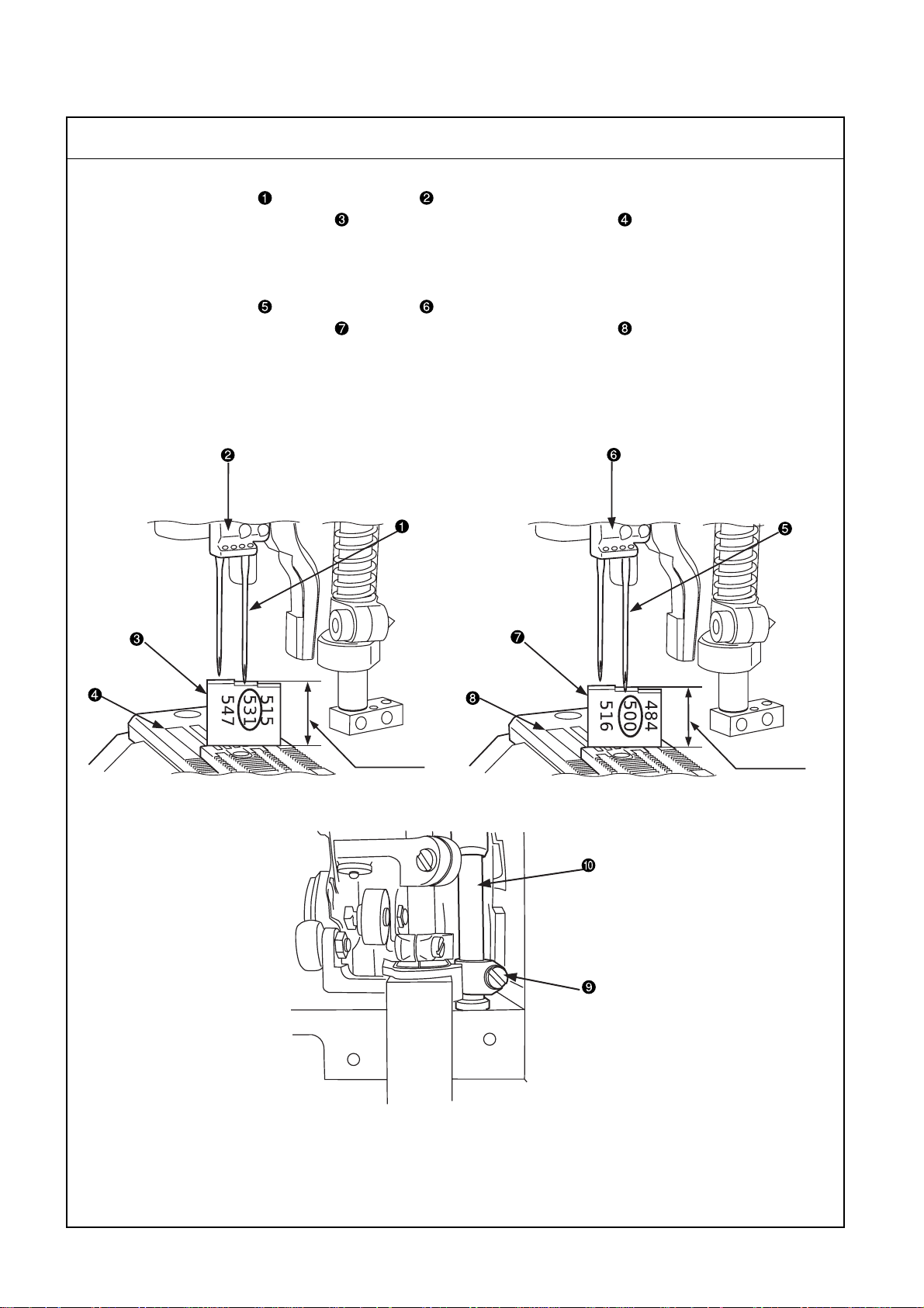
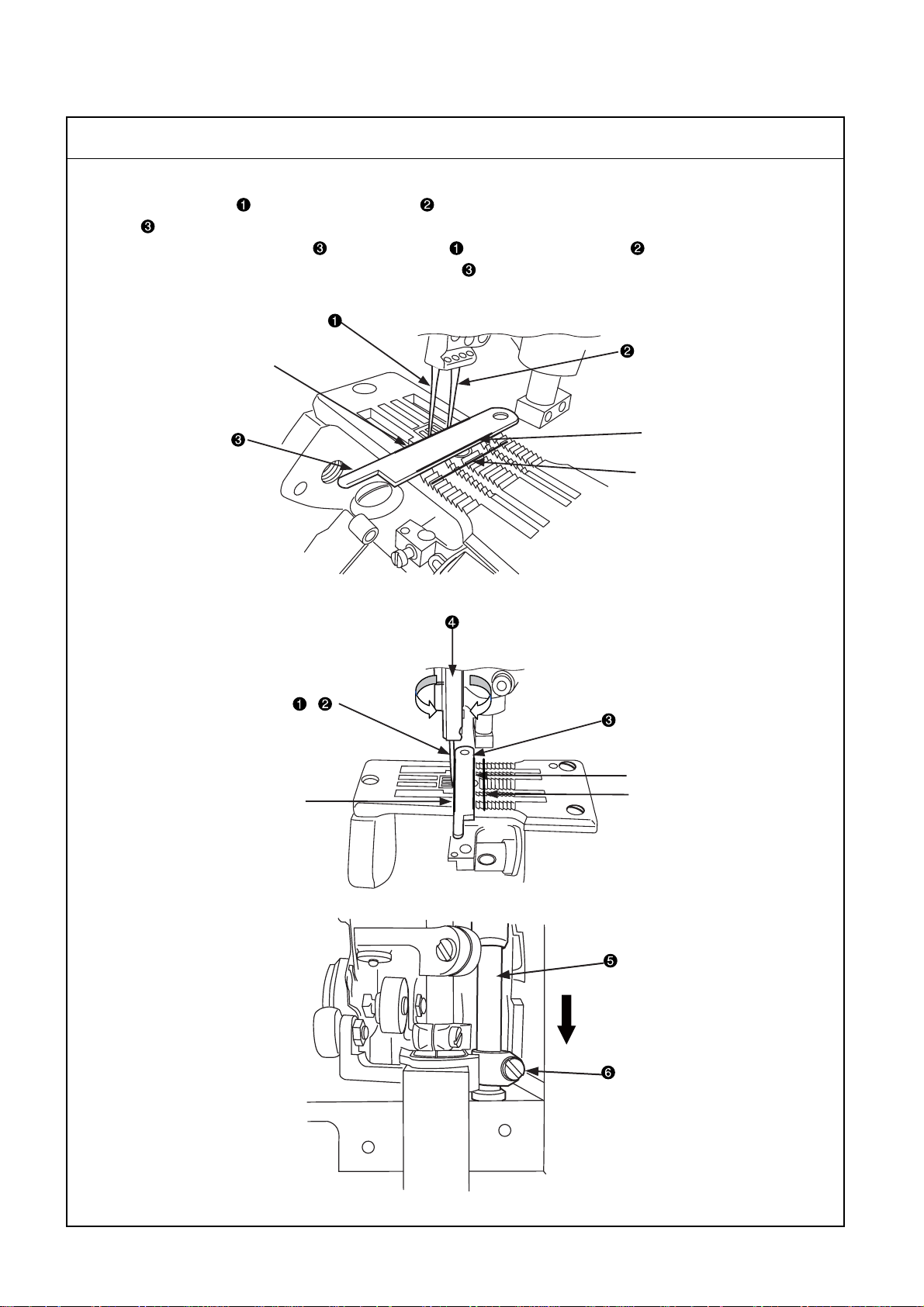
(2) Adjusting the height of the needle bar
Standard Adjustment
o For a needle gauge of 5.2mm
Mount the right needle on the needle clamp with the needle bar positioned at the upper dead point and
put the needle bar height gauge on the upper face of the throat plate . Check this condition in the
position of 531. The standard needle bar height is 13.5mm.
Use the needle bar height gauge (21227BU).
o For a needle gauge of 6.0mm
Mount the right needle on the needle clamp with the needle bar positioned at the upper dead point and
put the needle bar height gauge on the upper face of the throat plate . Check this condition in the
position of 500. The standard needle bar height is 12.7mm.
Use the needle bar height gauge (21227DS).
Needle gauge : 5.2mm
13.5mm
Needle gauge : 6.0mm
12.7mm
– 10 –
Page 15
Adjustment Procedures Results of Improper Adjustment
1. Remove the face cover and loosen the needle bar connecting bracket
setscrew to adjust the needle bar height by the means of the needle
bar height gauge or .
(Caution) When checking the needle bar height, change the needles
and , enter the needles and in the needle
clamps and to their uppermost ends, and stop them
in the correct positions. The needle shank has a flat section. Stop the needle with the flat section positioned in
front.
2. After the adjustment of the needle bar height, adjustment of the needle
array is carried out subsequently . Temporarily fasten the setscrew
of the needle bar connecting bracket .
(Caution) 1. When the needle bar connecting bracket setscrew
is fastened temporarily , the needle bar is required not
to come down even when it is rotated.
2. If the needle bar height is changed for a certain reason, readjustment is needed from the beginning, using the needle bar height gauge or .
When the needle bar height is
greatly different
o This will be a cause of stitch skip-
ping, needle breakage, or thread
breakage.
– 11 –
Page 16
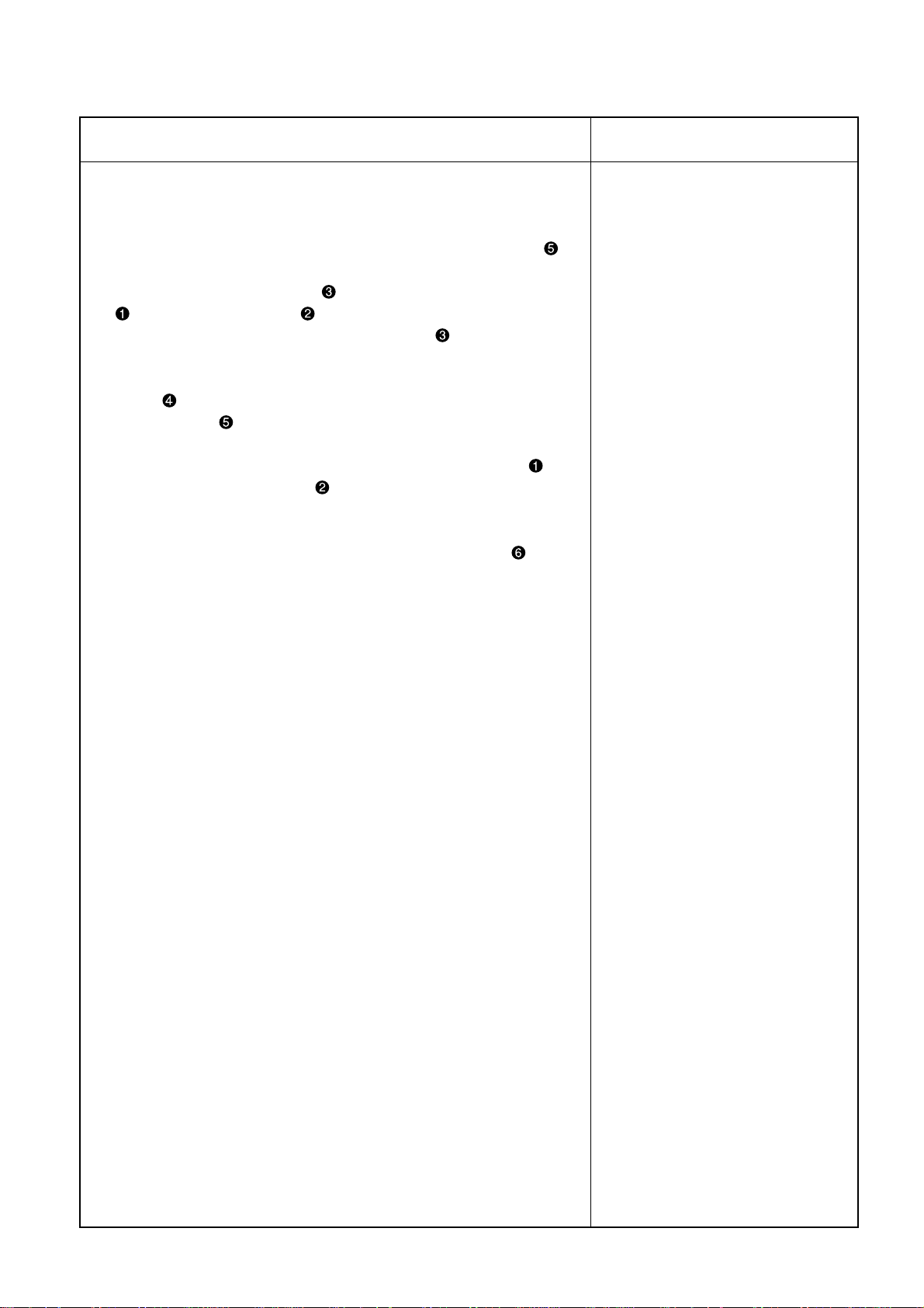
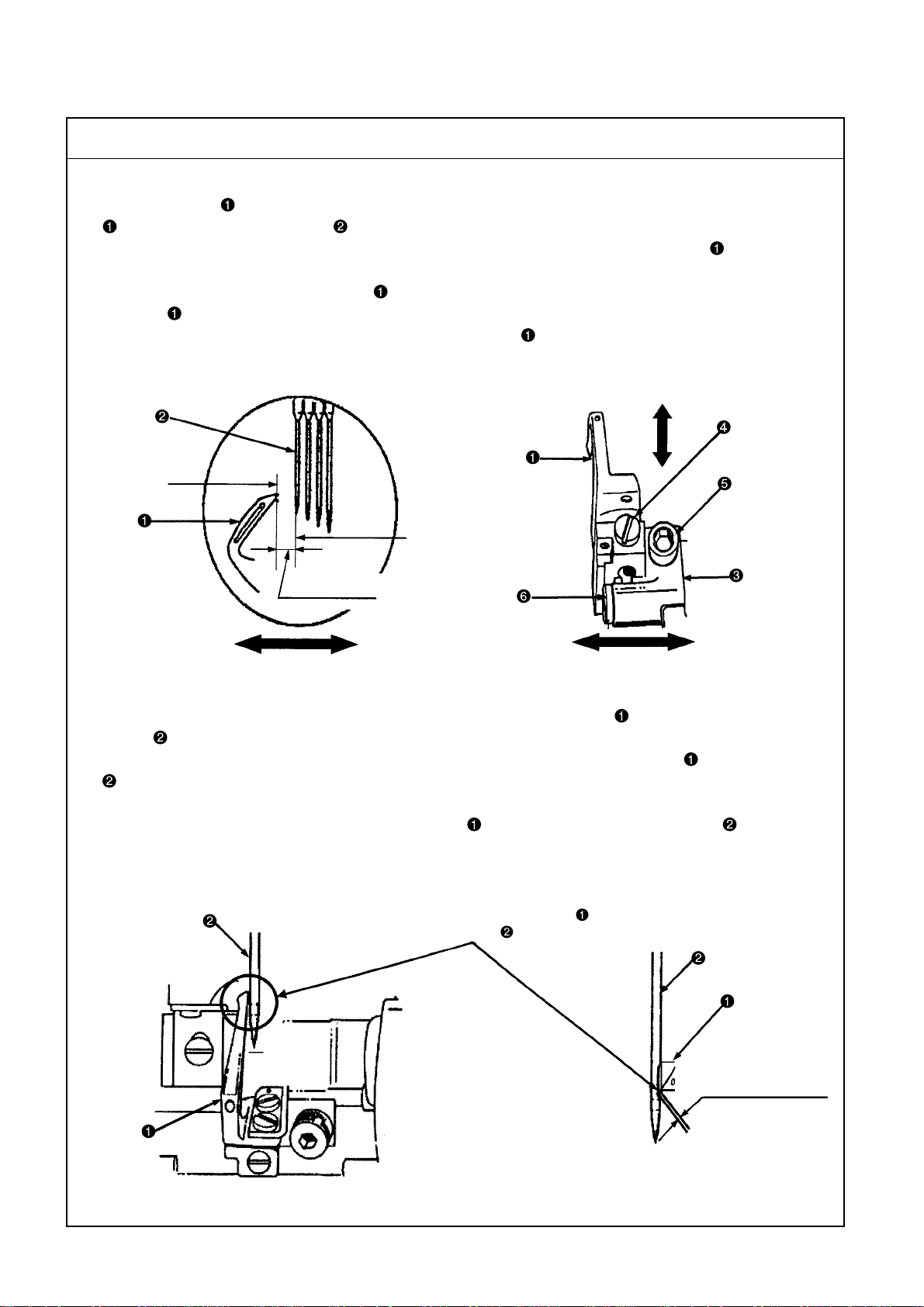
(3) Adjustment of needle array
Standard Adjustment
1. Needle array
Use the left needle and the retainer needle , and check the needle array based on Line A of the upper
knife .
Apply Line A of the upper knife to the left needle and the retainer needle on both sides. In this state,
the standard angle is that Line B of the upper knife is observed in parallel to Line C of the throat plate
groove.
A line
B line
C line
Right and left revolving
,
A line
B line
C line
– 12 –
Page 17
Adjustment Procedures Results of Improper Adjustment
Method of needle array check
1. Checks on the needle array parallelism are carried out after the
completion of needle bar height adjustments.
2. When checking the needle array parallelism, the needle bar is
lowered to the midpoint under the condition that no looper is attached.
3. Make Line A of the upper knife come in contact with the left needle
and the retainer needle on both sides. In this state, check the
parallelism between Line B of the upper knife and Line C of the
throat plate groove.
4. If no parallelism is secured, insert a spanner (7mm/9/32) in the needle
clamp and try to secure the needle array parallelism by turning
the needle bar to the right and left.
(Caution) If checking is intended without the dislodgment of the
looper, do it in the position where the left needle and
the retainer needle do not come in contact with the
rear side of the looper.
5. After the confirmation of parallelism, check the needle bar height
again and fix the needle bar connecting bracket setscrew .
When the needle parallelism is not
secured
o This will be a cause of stitch skip-
ping, needle breakage, thread
breakage, or destruction of throat
plate claws.
– 13 –
Page 18
(4) Right and left needle entry position adjustments
Standard Adjustment
1. Needle entry
Attach the needles (4 pcs.) and the retainer needle , and check the right and left needle entry spaces
in regard to the throat plate claws .
Examine the position where the left space becomes wider by 0.15mm than the right space. In this state, the
standard position is that the needles (4 pcs.) and the retainer needle (1 pc.), five needles in all, do not
touch the right and left throat plate claws .
Left space wider by
0.15mm
Right and left revolving directions
Right space
Left middle needle
regarded as the basis
Throat
plate
Left direction
– 14 –
Right direction
Page 19
Adjustment Procedures Results of Improper Adjustment
Needle entry adjusting positions
1. When adjusting the right and left needle entry, remove the front top
cover and the oil receiver.
2. Loosen the collar setscrew and move the collar toward the
front.
3. Loosen the hexagon coupling bolt and insert a screwdriver in the
eccentric pin . When the screwdriver is turned to the right and left,
the cylinder arm moves to the right and left.
4. Confirm the result of needle entry position adjustments.
5. After adjustments, tighten the hexagon coupling bolt to return the
collar to its initial position. Since then, tighten the collar setscrew
.
Method of confirmation
oTurning the eccentric pin to the right causes the cylinder arm
to move to the left.
oTurning the eccentric pin to the left causes the cylinder arm to
move to the right.
When the needle parallelism is not
secured
o This will be a cause of stitch skip-
ping, needle breakage, thread
breakage, or destruction of throat
plate claws as a result of getting flaws.
– 15 –
Page 20
(5) Looper adjustment
Standard Adjustment
1) Returning amount of the looper When the looper is positioned at the leftmost point, adjust the distance to 4mm from the tip of the looper
to the center of the left needle .
The amount of standard looper return is 4mm. However, the amount of return of the looper may somewhat
change according to the type of thread.
The final amount of return of the looper should be determined by making fine adjustments of the amount
of looper return while making threading and observing the stitches of trial sewing.
4mm shall be regarded as the amount of return of the looper during adjustments.
Right and left directions
Tip
Center
4mm (5/32)
Right and left directions
Forward and backward directions
2) Adjustment of a clearance between looper and needle The standard clearance is 0.0mm (light contact) when the tip of the looper reaches the center of the left needle . After rear needle holder adjustments, check the clearance again between the looper and the left needle
. For the final adjustment, this check should be carried out after making threading.
(Caution) 1. If no rear needle holder is provided, the above-mentioned checks should be carried out
in the state that the tip of the looper slightly touches the left needle .
2. The needles to be used come in two types; with a scoop (118GKS) and without a scoop
(118GAS).
Clearance between the looper
and the left needle
– 16 –
0.0mm
(Light contact)
Page 21
Adjustment Procedures Results of Improper Adjustment
1) Returning amount of the looper
1. Mount the looper on the looper base and fasten it with the
setscrew .
2. Loosen the looper base setscrew and move the looper base to
the right or left for adjustments.
3. After adjustments, tighten the looper base setscrew .
(Caution) When making adjustments by moving the looper base
to the right or left, the forward and backward positioning of the looper base is also changed.
During the right-left adjustment of the looper base ,
make adjustments of "7.-(5)-2), Adjustment of clearance
between looper and needle" simultaneously by means
of the setscrew .
When the amount of looper return,
changing with the type of thread, is
too much
oTightness of stitches becomes
worse for the left needle thread
and the stitches of thread tension
are degraded.
When the amount of return is small
o This can be a cause of stitch skip-
ping when the looper is re-
treated.
o The needle thread, second from
the right needle, is delayed from
the looper and it comes out si-
multaneously with the right needle
thread. Thus, the stitches of thread
tension are degraded.
o This is a cause of second stitch
skipping as seen from the left
needle .
2) Adjustment of a clearance between looper and needle
1. Loosen the looper base setscrew and turn the setscrew to
adjust the looper base by moving it forward and backward.
2. After adjustments, tighten the looper base setscrew .
o When the looper base is moved to the left, the tip of the looper
is separated from the left needle .
o When the looper base is moved to the right, the tip of the looper
comes in contact with the left needle .
(Caution) After the completion of adjustments in accordance with
"7.-(6) Adjustment of looper and needle bar timing" and
"7.-(7), 7.-(8) Adjustment of looper movement and motion locus", make readjustments, without fail, according
to "2) Adjustment of a clearance between looper and
needle".
– 17 –
Page 22
(6) Adjustment of looper and needle bar timing
Standard Adjustment
1. Looper and needle bar timing (synchronization)
Synchronization is adjusted after mounting the respective gauge parts. Turn the pulley in the forward direction and adjust the tip of the synchro-gauge rod to the graduation after the needle bar has been
stopped. The standard position is defined when the pulley is turned in the reverse direction and the tip of the
synchro-gauge rod stops at the same graduation for forward pulley rotation after the needle bar has
been stopped.
(Caution) When the pulley is turned in the forward/reverse direction, the standard value is defined if
the obtained figure is different by less than 1 from the graduation of the tip of the synchrogauge rod .
Tip of the synchrogauge rod
Reverse movement
US gauge Part No. 21227CG
Forward movement
Graduation
Thickness:
4mm
(Caution) Installation of the gauge indicated in
the above drawing falls on the new
36200L type. In regard to the installation of the gauge for the former type
36200, installation of the needle bar
torque tool is not required.
Right and left revolving
directions
Forward and backward
directions
(Caution) The main shaft coupling front and rear, and , are provided
with the fitting mark . Gauge check should be carried out after
making adjustments to the fitting mark .
– 18 –
Page 23
Adjustment Procedures Results of Improper Adjustment
How to mount and use the synchro-adjust gauge
1. Attach the needle bar torque tool to top of the needle bar and
tighten the setscrew . Then, move the needle bar to the lower
dead point.
2. Mount the gauge base on the presser pressure adjusting spring
and fix the needle bar height adjusting screw just above the
needle bar .
3. Insert the 4mm-thick portion of the synchro-gauge base in between the needle bar and the needle bar height adjusting screw
. Turn the needle bar height adjusting screw until it comes in
contact with the synchro-gauge base . In the state that a dimension (thickness) of 4mm is maintained, tighten and fix the needle bar
height adjusting nut .
4. Remove the synchro-gauge base and mount it on the looper .
Tighten the setscrew . When the pulley is turned in forward direction, the needle bar rises by 4mm and stops there. At this time,
adjust the tip of the synchro-gauge rod to the specified graduation position. (Within the scale range)
5. When the pulley is turned in reverse direction, the needle bar
rises, lowers, and stops. Confirm the graduation position of the tip of
the synchro-gauge rod . If there is any deviation by more than 1
from the graduation position in forward revolution, adjust the main
shaft coupling front and rear, and , respectively.
oIncorrect synchro-gauge position-
ing may cause stitch skipping.
Adjusting positions and method of adjustment
To make timing adjustments for the looper and the needle bar ,
remove the rear top cover and loosen three nuts of the main shaft
coupling front and rear, and , respectively. In the state that the
main shaft coupling rear is held, move the main shaft coupling front
to the right and left to adjust it.
(Spanner 1/4 inches for the nut )
oTurning the main shaft coupling front to the right causes the tip of
the synchro-gauge rod to go backward.
oTurning the main shaft coupling front to the left causes the tip of
the synchro-gauge rod to go forward.
(Caution) To move the main shaft coupling front , temporarily
fasten a nut that is located near the fitting mark during adjustment. If the nut is not fastened temporarily,
position of the tip of the synchro-gauge rod cannot
be made stable.
– 19 –
Page 24

(7) Adjustment of looper movement
Standard Adjustment
1. Looper movement
The looper movement is regarded as 0° at the rightmost point. When the pulley is turned in forward direction, the tip of the point gauge moves to the fan-shaped gauge in the direction of the arrow. In this
state, the standard value of 55° 40’ is obtained when the tip of the point gauge reaches the leftmost point.
Tip of the point gauge
0
°
° 40’
55° 40’
54
55° 40’
56
° 40’
Right and left directions
US gauge Part No. 21227CN
2. Looper movement gauge
Since the point gauge and the fan-shaped gauge are used to obtain a correct value of looper movement, the indicated looper movement must be checked each time the head section is adjusted.
0
°
40’
°
54
55° 40’
55° 40’
56
° 40’
Left direction
Right direction
(Caution) Check the point gauge and the
fan-shaped gauge at the time of
looper lot replacement.
– 20 –
Page 25

Adjustment Procedures Results of Improper Adjustment
How to mount and use the gauge
1. Loosen the setscrew and take out the spring stud . Loosen the
cover setscrew and take out the looper cover .
2. With the looper movement at the leftmost point, fix the point gauge
by means of the setscrew in the position where the front needle
holder of the looper is installed. Turn the pulley in forward direction toward the rightmost point.
3. Install the fan-shaped gauge where the spring stud has been
dislodged. At that time, the tip of the point gauge should be adjusted to Position 0∞of the fan-shaped gauge before tightening
the setscrew .
4. Turn the pulley further in forward direction and stop it where the looper
movement falls on the leftmost point. Check the position where the
tip of the point gauge stops at 55° 40’.
5. If the tip of the point gauge seems to stop on the right or left from
the standard position, the following adjustments should be carried
out.
o If the looper movement deviates
from the specified range, this will
cause failure in securing the correct tightness of stitches or stitch
skipping.
Adjusting positions and method of adjustment
To adjust the looper movement, remove the front top cover, loosen the
nut , and turn the changing screw to the right or left.
oTurning the changing screw to the right causes the looper move-
ment to decrease.
oTurning the changing screw to the left causes the looper move-
ment to increase.
(Caution) 1. When loosening the nut , it should be turned to the
right. (Reverse turn nut)
2. At the time of looper movement adjustments, temporarily fasten the nut and confirm the positions of
the fan-shaped gauge and the point gauge .
If the nut is not fastened temporarily for this check,
position of the looper movement may change.
– 21 –
Page 26

(8) Adjustment of looper movement locus
Standard Adjustment
1. Turn the pulley in forward direction and mount the avoid gauge when the looper shaft stays in the
extremely retreated position. At that time, confirm that the face of the plunger has coincided with that of
the avoid gauge . Turn the pulley further in forward direction to move the looper shaft forward. At the
same time, the plunger also moves forward.
When the looper shaft stays in the extremely advanced position, check whether the standard dimension
of 2.4mm has been secured in the position where the plunger is protruded extremely.
2.4mm
Looper shaft extremely advanced
Avoid gauge
Looper shaft extremely retreated
and plunger positioned in the same face
2. When the looper avoid gauge is not used
When the standard looper is installed and it is moved from the right to the left, the standard condition can
be attained when the tip of the right needle touches the point apart by 1/3 - 1/4 from the rear bottom face of
the standard looper .
(Caution) When the avoid gauge is not used, the looper locus cannot be checked unless the
presser, the throat plate, and the feed dog are dislodged.
Right needle
1/3 to 1/4
Left direction
Right direction
Top direction
Down direction
– 22 –
Page 27

Adjustment Procedures Results of Improper Adjustment
How to mount and use the gauge
1. Loosen the setscrew and take out the spring stud . Loosen the
cover setscrew and take out the looper cover .
2. Turn the pulley in forward direction and move the looper shaft to
the extremely retreated position. Fasten the avoid gauge with the
setscrew where the spring stud has been removed. As a cautionary note for mounting, the avoid gauge and the plunger
should be fixed so that their faces coincide with each other.
3. Turn the pulley in forward direction and move the looper shaft to
the extremely advanced position. At that time, measure the size of
the protrusion of the plunger .
For the size other than the standard size of 2.4mm, adjust it to the
standard size in the adjusting position.
When the amount of looper movement is insufficient
o The force of the needle touching
the rear side of the looper becomes strong, thus making the
needle tip blunt.
When the amount of looper movement is excessive
o The clearance between the needle
and the rear side of the looper be-
comes excessive, thus easily
causing stitch skipping behind the
looper.
Adjusting positions and method of adjustment
1. Loosen the setscrews (4 pcs.) and take out the cylinder side cover
.
2. Loosen the fixing screws and move the ball joint up and down
so that the looper movement locus can be adjusted. (Exclusive wrench
(TT85) to be used)
o Moving the ball joint upwards causes the forward/reverse move-
ment to decrease.
o Moving the ball joint downwards causes the forward/reverse move-
ment to increase.
– 23 –
Page 28

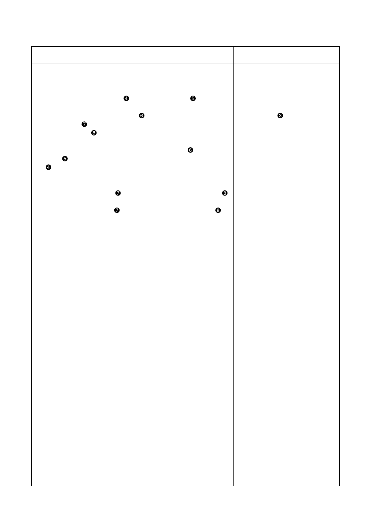
(9) Adjustment of the feed dog
Standard Adjustment
1. Height adjustment of differential feed dog
In the first place, attach the differential feed dog . When the differential feed dog is positioned at the
uppermost level, the standard position is obtained in terms of height where the root the tooth in the front
most row of the differential feed dog coincides with the upper face of the throat plate .
Driver groove leveled
Coincidence
2. Height adjustment of main feed dog
When the main feed dog and the differential feed dog are positioned at the uppermost level, adjust the
height of the main feed dog so that the crest of the tooth in the front most row of the main feed dog
attains the same height of the crest of the tooth in the rearmost row of the differential feed dog . This
position is a standard height of the main feed dog .
Standard position
Backward
Forward Backward
Forward
3. Gradient of the front/rear feed dog
The standard gradient of the front/rear differential feed dog is such that it is positioned somewhat lower
than the level of the throat plate .
The standard gradient of the front/rear main feed dog is such that it is positioned level to the throat plate
.
Forward
Horizontal line
Backward
Forward
Backward
– 24 –
Front lowering line
Page 29

Adjustment Procedures Results of Improper Adjustment
Adjusting positions and method of adjustment
1. For the eccentric pin of the feed dog, the standard positioning of
the driver groove is horizontal. If the driver groove seems to be inclined deviating from the standard positioning, loosen the setscrew
and adjust the eccentric pin of the feed dog until it assumes its
horizontal posture. Since then, tighten the setscrew .
2. In the first place, adjust the height of the differential feed dog to
the standard position. Then fix it by tightening the setscrew .
3. Then, adjust the height of the main feed dog to the standard position. After that, fix it by tightening the setscrew .
4. For the differential feed dog and the main feed dog , the front
and rear gradients and the horizontality are kept constant and cannot be adjusted.
(Caution) The top and bottom heights of the differential feed dog
and the main feed dog can be changed simultaneously by turning the eccentric pin of the feed dog.
In principle, however, this adjustment should not be carried out.
When the feed dog height is insufficient
o The amount of feed is decreased
and uneven feeding can occur.
o When the height of the rear
needle holder is lowered and the
margin of the needle contact position is reduced, this will cause
breakage of a needle or stitch
skipping.
When the feed dog height is sufficient
o This can be a cause of the mate-
rials pushed back to the front side,
or of giving rise to feed flaws.
o When the height of the rear
needle holder is raised and the
margin of the needle contact po-
sition is increased, this will cause
failure in producing loops and
stitch skipping.
– 25 –
Page 30

(10) Adjustment of needle holder
Standard Adjustment
1) Adjustment of rear needle holder Make adjustments so that the clearance between the left needle and the rear needle holder can attain
0.0mm (light contact) when the sewing machine pulley is turned in forward direction and the tip of the looper
reaches the position by 1mm toward the left side of the left needle .
The standard posture is that the rear needle holder lightly pushes the left needle .
1.0mm
Tip of looper
Left side
Forward and
backward
directions
0.0mm in position
by 1mm toward the
tip of the looper
(Light contact)
(Caution) After the completion of rear needle holder adjustments, check the clearance again be-
tween the left end of the looper and the center of the left needle . The clearance must
have been adjusted to 0.0mm (light contact).
2) Adjustment of forward movement needle holder Make adjustments so that the clearance between the left needle and the front moving needle holder can attain 0.0mm (light contact) when the sewing machine pulley is turned in forward direction and the tip of the looper reaches the center of the left needle . The standard posture is that the front moving needle holder keeps a light contact with the left needle in “0” position.
When the clearance is “0” between the
looper
clearance is also ì0î between the left needle
and the front moving needle holder .
tip and the left needle , the
– 26 –
Page 31

Adjustment Procedures Results of Improper Adjustment
1) Adjustment of rear needle holder
1. Turn the hand pulley in forward direction and stop it where the tip of
the looper stops in the position by 1mm toward the left side of the
left needle .
2. Loosen the setscrew and move the rear needle holder forward
or backward in order to adjust the clearance toward the left needle
to 0.0mm (light contact). When this clearance is secured, fix it by
tightening the setscrew .
oIf a clearance is actually developed
between the left needle and the
rear needle holder , this can be
a cause of needle breakage or
stitch skipping.
oIf the rear needle holder pushes
the left needle too much, this
can be a cause of needle blunt or
bend.
2) Adjustment of forward movement needle holder
1. Turn the hand pulley in forward direction and stop it when the tip of
the looper reaches the center of the left needle .
2. Loosen the setscrew and move the front moving needle holder
forward or backward in order to adjust the clearance to 0.0mm (light
contact) between the left needle and the front moving needle holder
. When this clearance is secured, fix it by tightening the setscrew
.
– 27 –
Page 32

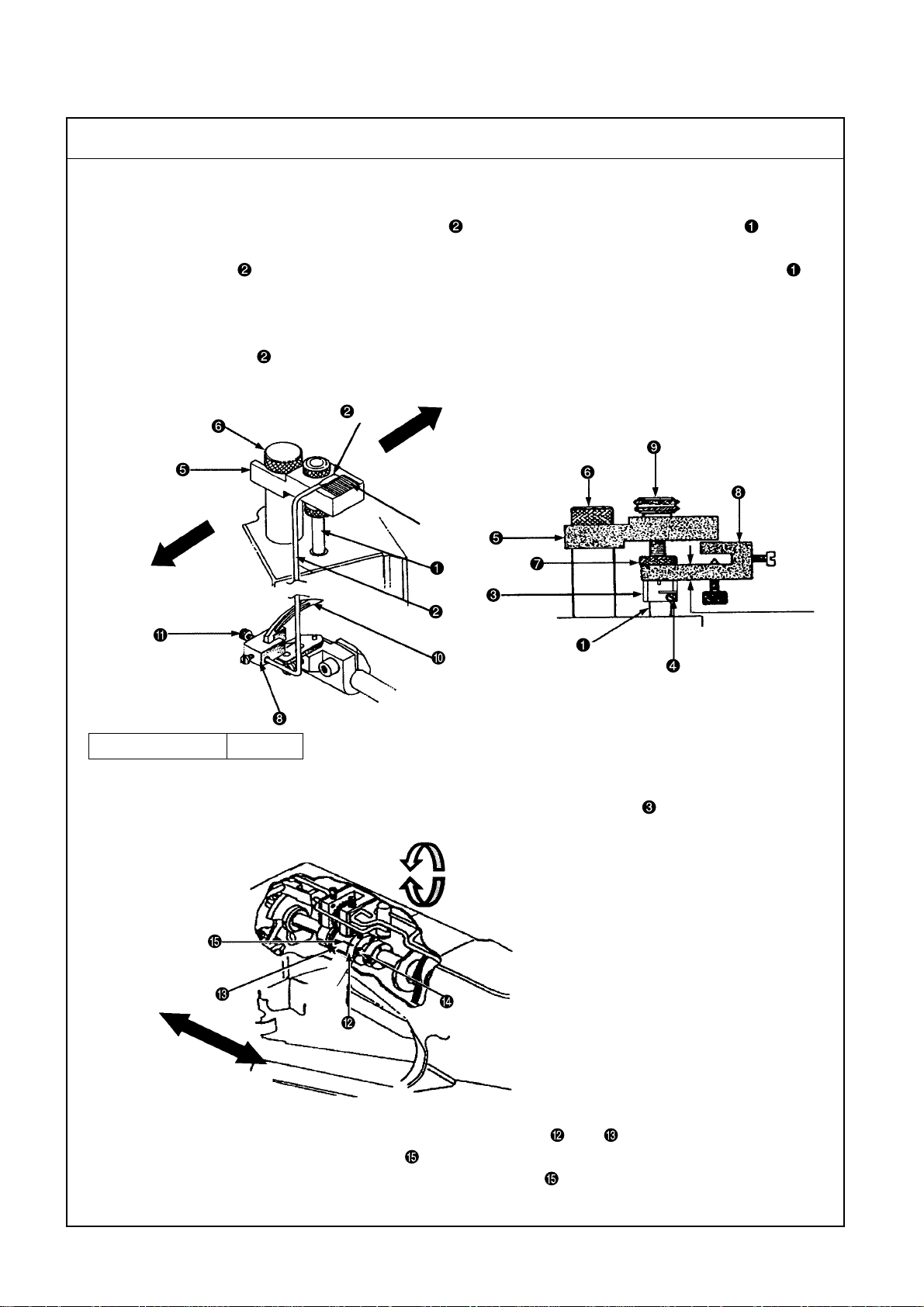
(11) Adjustment of feed mechanisms
Standard Adjustment
1) Stitch length adjustment (inch/10SPI-16SPI) The stitch length can be adjusted within the range of 1.6mm to 2.5mm. Standard adjustment is 2.1mm. For the adjustment of the stitch length, loosen the lever setscrew wards until the required length is secured.
(Caution) If the stitch length has been changed, check the rear needle holder and make a proper
readjustment.
Vertical direction
and move the lever upwards or down-
2) Adjustment of differential feed amount The amount of differential feed can be adjusted by moving the differential adjusting lever forward or backward. The graduation plate is provided with the engraved numbers of 1 to 9. Numbers 1 to 4 denote differential motion, Number 5 denotes no differential motion, and 6 to 9 denote forward differential.
Forward and backward directions
– 28 –
Page 33

Adjustment Procedures Results of Improper Adjustment
1) Stitch length adjustment
1. When the stitch length adjusting window spring is removed, the
lever setscrew can be seen.
o Loosen the lever setscrew to move the lever upwards and fasten
the lever setscrew there. This action increases the stitch length.
o Loosen the lever setscrew to move the lever downwards and fas-
ten the lever setscrew there. This action decreases the stitch length.
(Caution) No graduation is available for the adjustment of the stitch
length.
When the stitch length is changed
o If the forward or backward move-
ment of the main feed dog is
changed, the amount of contact is
also changed in regard to the left
needle and the rear needle holder.
Since this can be a cause of stitch
skipping, the rear needle holder
should be readjusted.
2) Adjustment of differential feed amount
1. When the differential adjusting lever is advanced in the reverse
differential direction (1 to 4), the differential ratio is decreased and
the sewed materials are extended.
2. When the differential adjusting lever is retreated in the forward
differential direction (6 to 9), the differential ratio is increased and the
sewed materials are shrunk.
*When fixing the differential adjusting lever , pinch it with two set-
screws and .
– 29 –
Page 34

(12) Adjustment of presser main body mounting
Standard Adjustment
1. Adjustment of presser main body mounting
After the completion of "7. Standard adjustments (1) to (1 1)", mount the presser main body . When mounting the presser main body , adjust the fancy thread carrier so that its claws are positioned in the center
of the left needle and the left middle needle. Also make adjustments so that no clearance is secured between
the presser main body and the presser guide right and presser guide left . The condition should be
such that the presser can move lightly in both upward and downward directions.
2. Presser main body assembly procedures
(1) Simultaneous mounting of the presser bar and the presser bar guide
For presser bar guide positioning after the completion of mounting of the presser main body ,
secure a gap of 7mm between the presser bar guide bottom and the ball joint top at the lower dead
point of the needle bar . Since then, tighten the setscrew . The specified clearance is 1mm between
the presser bar guide and the minute-quantity presser adjusting pin . If the clearance is found to be
other than 1mm, make adjustments by moving the minute-quantity presser adjusting pin upward or
downward.
(2) Mount the presser main body with the needle bar set at the upper dead point.
(3) Check the position of claws of the fancy thread carrier .
(4) Using the presser guide right and the presser guide left , fix the right and left sides of the presser
main body .
(5) Mount the presser spring and the presser pressure adjusting screw .
(6) After the completion of the above procedures, return to (1) and readjust the presser bar guide .
Clearance:
1mm
7mm
Left side of
the presser
main body
Center
Presser bar hole
Right side of
the presser
main body
Carrier claws
Left needle
Left middle needle
– 30 –
Page 35

Adjustment Procedures Results of Improper Adjustment
How to mount the presser main body
1. Get the minute-quantity presser adjusting pin inserted in the presser
bar guide and insert the presser bar in the presser bar bush
and the hole of the presser bar guide . Mount them at the same
time and leave the conditions as they are.
2. Insert the driving link of the presser main body in the driving
sleeve . Insert the presser bar in the driving link hole and the
presser bar hole of the presser main body . Since then, tighten the
setscrews .
3. Lightly push the left side of the presser main body until it comes in
contact with the presser guide right . In this state, turn the hand
pulley in forward direction to confirm that claws of the fancy thread
carrier are located in the center of the left needle and the left
middle needle.
(Caution) If claws of the fancy thread carrier seem to stay devi-
ating to the right or left against the needle, loosen the
setscrew and move the presser guide right to the
right or left to check positioning. After confirmation, fix
this setting by tightening the setscrew .
4. Let the right side of the presser main body touch the presser guide
right to hold the left side of the presser main body with the aid
of the presser guide left . Fix them with two setscrews . At that
time, make use not to leave any clearance between the presser main
body and the presser guides right and left so that the presser
main body can move lightly both upward and downward.
5. Upon the completion of adjustments of 1 to 4 above, make adjustments of (5) and (6) described at left.
o When the presser bar guide is
installed, actions of adjustments
should be taken always at the
lower dead point. Otherwise, the
presser may float to cause adverse feeding of materials.
o If claws of the fancy thread carrier
deviate to the right or left from
the center position, this can be a
cause of needle breakage.
o If there is any clearance on the
right or left of the presser main
body , this can be a cause of
stitch skipping or needle breakage.
– 31 –
Page 36

(13) Adjustment of the presser main body proper
Standard Adjustment
1) Adjustment of presser lifter connecting lever The standard clearance is 1.0mm between the lever link and the presser bar guide while the needle bar is located at the lower dead point.
Right and left direction
1.0mm
2) Adjustment of presser lifting strap plunger The standard clearance is 0.4mm between the bottom section of the needle clamp and the top fancy looper when the presser main body is lifted while the needle bar is kept located at the lower dead point.
0.4mm
3) Adjustment of minute presser lifting If feeding flaws or traces seem to remain in the materials, make fine adjustments of the presser main body in the upward direction. Adjust the height of the presser main body to avoid feeding flaws or traces in the materials.
(Caution) Since the presser main body is floated during sewing, this function should be utilized
adequately according to the type of sewing materials.
The standard clearance is 1.0mm.
Tightening the minute-quantity
presser lifter
ance to decrease and presser
floating to increase.
causes the clear-
Upward
direction
– 32 –
1.0mm
Page 37

Adjustment Procedures Results of Improper Adjustment
1) Adjustment of presser lifter connecting lever
Loosen the setscrew and move the lift connecting lever to the
right or left. Confirming the attainment of the standard size of 1.0mm,
tighten the setscrew .
2) Adjustment of presser lifting strap plunger
Loosen the nut while the needle bar stays at the lower dead point
and turn the strap plunger clockwise until it comes in contact with
the balancer. Then, turn it counterclockwise slowly to lift the presser
main body . At that time, make adjustments so that the bottom
section of the needle clamp and the top fancy looper do not
touch each other. Since then, tighten the nut .
o When the clearance is increased
between the lever link and the
presser bar guide , the amount
of rise in the presser main body
is decreased.
oWhen the presser main body
is lifted while the needle bar stays
at the lower dead point, the bottom section of the needle clamp
may come in contact with the
top fancy looper . In such a
case, there may be a problem of
stitch skipping or destruction of
parts.
3) Adjustment of minute presser lifting
When the lock nut is loosened and the minute-quantity presser
lifter is turned, the minute-quantity presser adjusting pin rises
to float the presser main body . Adjust the presser main body to
the required height and tighten the lock nut .
(Caution) Too much lifting of the presser main body will result
in a problem of failure in material feeding.
– 33 –
Page 38

(14) Adjustment of top fancy looper and fancy thread carrier
Standard Adjustment
1) Stroke position adjustment of drive sleeve The standard position of the driving sleeve can be defined when the hand pulley is turned in forward direction and the standard clearance of 2mm is secured between the head of the link setscrew and the closest point on the rear side of the needle clamp .
2.0mm
Right and left directions as seen from behind
2) Amount of fancy thread carrier injection Claws of the fancy thread carrier enter the center of the left needle and the left middle needle. When the tip of the carrier claws is located in the most advanced position, the standard distance is 3.5mm from the needle front to the front face of the fancy thread carrier . Make a final check by passing the fancy thread. The standard position is secured when the fancy thread at the tip of the fancy thread carrier is caught by the tip of the right/left needle.
(Caution) The right and left positions of the fancy thread carrier should be adjusted when the
presser is installed.
Left needle
Forward
movement
Left middle needle
3.5mm
Front face of the fancy
thread carrier
Left needle
Front face of
the needle
3.5mm
Tip of the carrier claws
Left middle needle
Forward and backward directions
– 34 –
Page 39

Adjustment Procedures Results of Improper Adjustment
1) Stroke position adjustment of drive sleeve
When the head of the link setscrew comes closest to the rear face
of the needle clamp , loosen the setscrew of the driving sleeve
lever and move the driving sleeve to the right and left to secure
the standard clearance of 2mm. Since then, tighten the setscrew .
When the driving sleeve is moved to the right and left as seen
from behind, the clearance becomes as follows:
o The clearance is narrowed when the driving sleeve is moved left-
ward.
o The clearance is widened when the driving sleeve is moved right-
ward.
(Caution) When the setscrew is loosened, the driving sleeve
is lowered and a vertical clearance may be developed.
Tighten the setscrew after confirming that there is no
clearance after adjustments.
o If position adjustment is incorrect,
this can be a cause of fancy stitch
skipping, needle breakage, or destruction of parts.
2) Amount of fancy thread carrier injection
Loosen the setscrew and move the fancy thread carrier forward and backward to adjust the injection size to 3.5mm. Since then,
tighten the setscrew .
o This can be the cause of needle
breakage or stitch skipping.
– 35 –
Page 40

(14) Adjustment of top fancy looper and fancy thread carrier
Standard Adjustment
3) Leftmost point of top fancy looper While the top fancy looper is moved leftward, the fancy thread passes through the slider section and the position of being hooked on the thread hanger section is located at the extreme left. When the tip of the top fancy looper reaches the extreme left point, the standard size of 2.0mm from the left middle side face of the presser main body is secured.
Left middle side of face the
presser main body
Thread slider
section
2.0mm
Right and left
directions
Top fancy looper
Tip leftmost point
Thread hanger section
4) Clearance developed at the time of crossing between the fancy thread carrier and the tip of the top fancy looper When the fancy thread carrier is retreated, it is crossed by the tip of the top fancy looper . The standard clearance is 0.4mm when both items make the closest approach.
0.4mm
The crossing clearance is
0.4mm between the fancy
thread carrier
treated and the tip of the
top fancy looper
being re-
.
Retainer needle
5) Rightmost point of top fancy looper The needle lowers when the tip of the top fancy looper reaches the rightmost point and then moves to the left. The standard positioning is that the fancy thread is not caught by the retainer needle at that time.
6) Height of top fancy looper The height of the top fancy looper is kept unchanged.
Upper clearance
– 36 –
Lower clearance
Page 41

Adjustment Procedures Results of Improper Adjustment
3) Leftmost point of top fancy looper
Loosen the setscrew when the tip of the top fancy looper is
located at the extreme left, and move the looper to the right and left
to secure a dimension of 2.0mm. Since then, tighten the setscrew
.
4) Clearance developed at the time of crossing between the fancy thread
carrier and the tip of the top fancy looper
Loosen the setscrew to adjust the amount of injection of the fancy
thread carrier . Then, loosen the top fancy looper setscrew and
secure a dimension of 0.4mm by making right and left fine adjustments for the top fancy looper simultaneously.
o If the fancy thread is not caught
by the thread hanger section of the
top fancy looper , this can be a
cause of top fancy stitch skipping.
o If there is a problem in clearance
adjustments, this can cause breakage of parts.
5) Rightmost point of top fancy looper
If there is no problem in adjustments of the top fancy looper at the
leftmost point and of the fancy thread carrier mechanisms, the
rightmost positioning is automatically secured for the top fancy looper.
6) Height of top fancy looper
If a vertical clearance is developed at the time of adjustment of the
top fancy looper , the top fancy looper is lowered. Tighten the
setscrew to eliminate such a vertical clearance.
– 37 –
o If the rightmost position of the top
fancy looper deviates to the
right too much, the fancy thread
comes out of the right needle.
o If vertical rattling is generated in
the top fancy looper , this can
be a cause of stitch skipping or destruction of parts.
Page 42

(15) Adjustment of top fancy cam and bobbin thread cam
Standard Adjustment
1) Adjustment of top fancy cam
1. While the top decoration cam is moved leftward, the decoration thread passes through the thread
slider section of the top decoration looper and is caught by the thread hanger section.
The standard position is secured when the fancy thread is released from the crest point of the top fancy
looper after the thread has been hooked on the thread hanger section.
2. The standard height (spun thread) of the top fancy thread path is 2.4mm above the top face of the cam
thread path mounting base .
Cam’s crest point
Top fancy thread
2.4mm
Vertical direction
Right and left
directions
Center
(Caution) The amount of thread drawing out may change according to the type of the thread used.
The adjusting height of the top fancy thread path also changes.
2) Adjustment of bobbin thread cam
1. The standard size is 2mm for the position where the bobbin thread (spun thread) is released from the
releasing point of the bobbin thread cam . This size is measured from the side face of the contact screw
in the cam groove position to the upper end of the cam groove.
Upper end of the
cam groove
2mm
Screw side face
Bobbin thread
Thread releasing point
Right and left directions
Center
Coincidence of the thread path mounting
with the right end of the bobbin
base
thread guide thread path
Right and left directions
(Caution) The cam position should be advanced when a wooly thread (high elongation) is used.
Since the wooly thread is stretchy , it is necessary to increase the amount of thread draw-out.
– 38 –
Page 43

Adjustment Procedures Results of Improper Adjustment
1) Adjustment of top fancy cam
1. Check the timing when the upper fancy thread is released from the
crest position of the outer periphery of the cam. Loosen the setscrew
and then tighten it after adjustments.
2. For adjustments of the upper fancy thread path , loosen the setscrew and adjust the upper fancy thread path to the center of
the upper fancy cam in order to secure the height of 2.4mm. Since
then, tighten the setscrew .
2) Adjustment of bobbin thread cam
1. Check the timing when the bobbin thread is released from the thread
releasing point on the outer periphery of the bobbin thread cam .
Loosen the cam setscrew and then tighten it after adjustments.
2. To secure the mounting position for the bobbin thread guide thread
path , adjust it to the center of the bobbin thread cam and tighten
the setscrew . Check the right and left positioning, and let the cam
thread path mounting base coincide with the right end of the bobbin thread guide thread path .
3. If the amount of thread draw is increased for the bobbin thread path
, loosen the setscrew and move the bobbin thread path to the
left. Tighten the setscrew in the adequate position where the required amount of thread is available. To reduce the amount of thread,
move the bobbin thread path rightward.
o If the fancy thread is not caught
by the thread hanger section of the
top fancy looper, this can be a
cause of top fancy stitch skipping.
When the upper fancy thread path
is too low:
o Since the amount of fancy thread
becomes small, this can be a
cause of needle breakage or stitch
skipping of the left middle needle.
In addition, the sewing width of the
upper fancy thread is narrowed.
When the upper fancy thread path
is too low:
o Since the amount of fancy thread
becomes large, this can be a
cause of stitch skipping.
This can be a cause of stitch skip-
ping of idle loops. There is possi-
bility of clogging due to reduced
development of idle loops.
o When the bobbin thread cam
is advanced, the amount of bob-
bin thread is increased. When it is
delayed, the amount of bobbin
thread is decreased.
– 39 –
Page 44

(16) Knife adjustment
Standard Adjustment
1) Lower knife adjustment Insert the lower knife from the left side of the presser main body, left. The standard size is 0.8 to 1.6mm from the right side of the presser main body left to the front corner section of the lower knife right.
Left side face of the
presser main body
left
Right side face of
the presser main
body
left
2) Upper knife adjustment Turn the hand pulley in forward direction and stop the upper knife driving bracket in the leftmost position. Insert the upper knife from the right side of the presser main body right and let it cross the lower knife
. The standard crossing size is 0.4mm between the front corner section of the lower knife right and the
front corner section of the upper knife left.
Front corner section of
the lower knife right
0.8 to 1.6mm
Right direction
Right side of the
presser main body,
right
Front corner section
of the upper knife
left
Right and left directions
Crossing size of 0.4mm
Front corner section
of the lower knife
right
3) Pressure adjustment of upper knife When the upper and lower knives and are crossing, the standard size is 1.6mm between the lower face of the knife base guide and the top face of the mounting section for the knife holder shank
Lower face of the knife base guide
1.6mm
Top face of the mounting section for
the knife holder shank
– 40 –
Page 45

Adjustment Procedures Results of Improper Adjustment
1) Lower knife adjustment
1. Loosen the setscrew and move the lower knife to secure the
standard size of 0.8 to 1.6mm. Since then, tighten the setscrew .
2) Upper knife adjustment
1. Attach the upper knife auxiliary plate to the knife holder shank
and install the upper knife fixing block . Since then, tighten the
setscrew .
2. Turn the hand pulley in forward direction to the leftmost position of
the upper knife driving bracket . Insert the upper knife from the
right side of the upper knife fixing block and tighten the setscrew
after confirming that the standard crossing size of 0.4mm has
been secured in conjunction with the lower knife .
3. If the right to left angle of the upper knife seems to be inadequate
for the lower knife in regard to the meshing condition between the
upper and lower knives and , loosen the screw and change
the angle of the upper knife .
o According to the right and left po-
sitioning mesh between the upper
and lower knives and , the
amount of material stacks is
changed.
o If the knives become blunt,
stitches at the edge of material
cloth become unstable. This can
be a cause of stitch skipping.
o If the spring pressure is too strong
for the upper knife , the sharpness of the knife will soon be lowered.
3) Pressure adjustment of upper knife
1. At the time of crossing of the upper and lower knives and ,
loosen the setscrew and measure the distance of 1.6mm between
the upper face of the knife holder shank of the upper knife driving
bracket and the lower face of the knife base guide . After this
distance has been confirmed, tighten the setscrew .
– 41 –
Page 46

(17) Adjustment of upper knife drive lever
Standard Adjustment
Positiion of upper knife drive lever
1. When the hand pulley is turned in forward direction and Size C is secured for the needle bar height, the
standard position is located at 6:00 for the upper knife driving lever .
Upper face of the machine head section
A
Position of 6:00
Upper face of the needle bar
B
C
72.2mm
Right and left directions
– 42 –
Page 47

Adjustment Procedures Results of Improper Adjustment
How to determine Size
C
1. Set the needle bar at the lower dead point and measure Size A from
the upper face of the needle bar to the upper face of the machine
head.
2. Then, with the needle bar set at the upper dead point, measure Size
B
from the upper face of the needle bar to the upper face of the
machine head.
3. Make a calculation of B – A÷ 2 = D to determine Size D. The
required Size C is obtained from D + A.
Adjustment procedures
1. Loosen the setscrew of the needle bar lever and adjust the
upper knife driving lever to the position of 6:00. Then, tighten the
setscrew .
2. The standard size is 72.2mm from the center of the ball joint to the
center of the ball joint .
3. To adjust the right and left ball joints and , loosen the right and
left nuts and , and turn the joint rod . Confirm the size of
72.2mm and tighten the right and left nuts and .
o If the mounting posture of the up-
per knife driving lever is incorrect, the sharpness of the knife will
soon be lowered.
o If the right and left ball joints
and have wrong sizes, it is impossible to adjust the top fancy
looper and the fancy thread carrier.
– 43 –
Page 48

(18) Adjustment of needle thread path
Standard Adjustment
1) Adjustment of needle thread guide bar The standard height (spun thread) of the needle thread guide bar is defined by T able 1 to 4 below from the upper face of the needle thread guide base to the lower end of the hole. If the needle thread tension is needed according to the type of the thread, lower the needle thread guide bar .
Dimensions of needle thread guide bar
Needle thread guide bar
1 234
Standard height 28mm 30mm 32mm 40mm
2) Adjustment of needle holder adjusting pin The standard height (spun thread) of the needle thread holder adjusting pin is defined by T able 5 and below from the upper face of the needle thread holder base to the crest point of the needle thread holder adjusting pin .
Dimensions of needle holder adjusting pin
Needle holder adjusting pin
Standard height 4.5mm 4.0mm 3.5mm 3.0mm
5 678
4
3
2
1
Standard
height
5
6
7
8
6
Standard height
3) Adjustment of needle thread presser spring In regard to the height of the needle thread presser spring mounted on the needle thread path base , the standard size is 2.5mm between the tip section of the needle thread presser spring and the head top of the screw .
Tip of needle thread presser spring
2.5mm
– 44 –
Page 49

Adjustment Procedures Results of Improper Adjustment
1) Adjustment of needle thread guide bar
Loosen the setscrew of the needle thread guide bar of 1 to
to adjust the height. After adjustments, fix the setscrew .
o Lowering the needle thread guide bar causes the needle thread
to be tightened.
o Raising the needle thread guide bar causes the needle thread to
be loosened.
2) Adjustment of needle holder adjusting pin
Loosen the setscrew of the needle thread holder adjusting pin
of 5, 6 to adjust the height. After adjustments, fix the setscrew .
Size 7, 8 is for reference.
o Raising the needle thread holder adjusting pin causes the needle
thread loop to be enlarged.
o Lowering the needle thread holder adjusting pin causes the needle
thread loop to be diminished.
4
o More precise adjustment to the
standard size is needed for the
needle thread guide bar as it is
positioned closer to the looper.
Otherwise, the thread tension may
become worse.
oSince the left and left middle
needles are located near the
looper, the needle thread holder
adjusting pin has to be adjusted
to the standard size correctly . Otherwise, loop formation will get
worse and stitch skipping may occur.
3) Adjustment of needle thread presser spring
Loosen the setscrew to turn the spring holder and make adjustments to secure the size of 2.5mm between the tip section of the
needle thread presser spring and the head top of the screw .
Then, tighten the setscrew .
* Role of the needle thread presser spring
The needle thread resistance is effective in stabilizing loop formation.
When the hand pulley is turned in reverse direction and then in forward direction for starting, the needle thread once loosened is tensed
again by the function of the needle thread presser spring . For this
reason, stitch formation is improved at the time of starting.
– 45 –
o If the needle thread presser spring
has no needle thread resistance, stitch skipping may be
caused at the time of starting.
Page 50

(19) Adjustment of tension disk rise and protection cover
Standard Adjustment
1) Adjustment of tension disk rise The standard positioning is that the tip of the disk rise pin keeps contact with the top tension disk when the presser main body rises by 0.8mm above the upper face of the throat plate and that the top tension disk keeps rising when the presser main body is located at the crest point. The standard size is 7.5mm between the tip of the disk rise pin and the upper face of the tension thread path .
0.8mm
7.5mm
Driver groove
2) Adjustment of protection cover When the protection cover is shut, this protection cover holds the chips guard . The standard mounting posture is that there is no front and rear play around the chips guard .
– 46 –
Page 51

Adjustment Procedures Results of Improper Adjustment
1) Adjustment of tension disk rise
Insert a screwdriver in the driver groove of the tension disk rise shaft
. Loosen the setscrew of the lift lever and turn the screwdriver to adjust the height of the disk rise pin to 7.5mm. Since
then, tighten the setscrew .
o When pulling out the needle
thread as well as the top and bottom fancy threads, it is necessary
to lift the top tension disk .
2) Adjustment of protection cover
Loosen the hexagon head bolt and make the stepped position of
the washer coincide with the stepped position of the protection
cover . Turn the bolt where the protection cover is tightened.
Use a spanner wrench (21388Y) to fix the washer and tighten the
hexagon head bolt . The spring settles in the hole of the protection cover and makes it stabilized.
o The protection cover is used
to protect the operator when a
needle is broken and pointed objects fling out.
o When the chips guard is stabi-
lized, the presser and the needle
section can be protected against
chips.
– 47 –
Page 52

(20) Adjustment of lapformer
Standard Adjustment
1. Adjustment of lapformer
This is an exclusive both side trim center guide used to adjust the right and left width of the materials in stack.
When the setscrews and are loosened and the lapformers , , and are moved to the right or left,
it is possible to change the tip position and adjust the stack width of materials.
Since the standard value is changed by the lapformers , , and specified below, the presser main
body, the types of rear spring parts, and material cloth, adjustments are carried out by repeating sewing
several times.
2. Union Special standard lapformer (B) (Part No: 23420DB)
This is the universal type that is applicable to both light and medium heavy materials. The material stacks do
not come in full laps. Lapping is possible up to approximately three stitches on the front and rear. According
to materials, full-lap products may be available.
3. Domestic standard lapformer (C) (Part No: 23420DE)
This is the universal type that is applicable to both light and medium heavy materials. The tip section of the
lapformer can be shifted very much to the left so that the width of material laps can be increased. A
condition close to a full lap (fourth stitch on the front and rear) can be attained. To increase the width of laps,
it is important to select the rear spring correctly. Selection should conform to the nature of raw materials.
Difference between Part Nos. 23420DB (DB) and 23420DE (DE)
For the DE, the setscrew hole section has a stepped part; in the
shape of an oblong hole to the right and left. Therefore, it is
possible to shift the tip section of the lapformer to the left more
than the DB.
4. Lapformer exclusive for light weight materials (D) (Part No: 23420CZ)
This type is most suitable in the case when the amount of laps of light weight raw materials has to be applied
to a full lap.
(Caution) Even the light weight materials cannot be sewn if the goal product has steps on the way.
– 48 –
Page 53

Adjustment Procedures Results of Improper Adjustment
How to mount and adjust the lapformer
1. Fix the leaf spring to the bottom face of the slide block by
means of the setscrew .
2. Put the slide block in between the right and left slide plates
and . T emporarily fasten the right and left slide plates and by
means of the setscrews (6 pcs.).
3. Shift the tip sections of the lapformers , , and respectively to
the left and tighten the setscrews and .
4. Tighten the setscrews (6 pcs.) of the right and left slide plates
and so that the slide block can move forward and backward.
5. Upon the completion of the above, advance the slide block until it
stops.
6. Try to sew the raw materials several times and examine the right to
left lap width of the materials. If the lap conditions seem to be inadequate, loosen the setscrews and and move the tip sections of
the lapformers , , and to the right or left. After readjustment,
tighten the setscrews and .
o When the tip sections of the
lapformers , , and are
moved to the left, the lap width is
increased.
o When the tip sections of the
lapformers , , and are
moved to the right, the lap width is
decreased.
Tip section of the
lapformer
, ,
– 49 –
Page 54

8. Lubrication
1. Oil lubrication and check point
The sewing machine head section is of the rotary pump type auto lubrication system.
Remove the oil circulation check windows (front) and (rear), and , and feed a lubricant as high as the level
between the upper and lower engraved marker lines of the oil gauges (front and rear), and .
When the lubricant has been replenished, mount the oil circulation check windows (front) and (rear), and .
2. Oil drain spot
To replace the lubricant, remove the oil drain (front) and (rear) screws and . Upon the completion of oil
drainage, tighten the oil drain (front) and (rear) screws and .
(Caution) To confirm the amount of oil at the oil gauge (rear) , check the crest point of the oil level
indicator that is actuated by an oil float. In some cases, the oil level indicator does not come up
immediately. Make sure not to commit overfilling of the oil in such a case.
Upper and lower engraved
marker lines of the oil gauge
(rear)
Upper and lower engraved
marker lines of the oil gauge
(front)
– 50 –
Page 55

9. List of rear spring
(1) One side trim
Model name Part No. of standard presser
36200L100-52
36200U300-52
36200L100-60
36200U300-60
36220A
36220K
Standard
36231AY, 36232AY 36231AZ, 36232AZ
Length Short Long
Hardness Weak Weak
Option
36231AH, 36232AH 36231AJ, 36232AJ 36231AD, 36232AD
Accessories in the
same package
Length Short Long Long
Hardness Strong Strong Strong
Features
* If the length is short, the property of tight turns is available and raw materials can be handled as closer as
possible to the knife position. Therefore, the effect is substantial in regard to right and left material shifts. ••• For
thigh patch-up for ladies’ shorts, etc.
* If the length is long, favorable factors can be expected in regard to biting at the beginning of sewing. The feeding
force is favorable and the stepped sections can be processed smoothly. ••• Applicable to taped parts in trainers
and men’s briefs and underwear
* Feeding flaws are hardly attached to soft materials. This is effective for light weight materials. (Thickness: 0.36mm)
* The feeding force is favorable for hard materials. This is effective for coarse materials. (Thickness: 0.5mm)
– 51 –
Right material cutting Left material cutting
Page 56

(2)Both side trim
Model name Part No. of standard presser
36200L200-52
36200U300-52
36200L200-60
36200U300-60
36220E
36220W
J36231C, J36232C J36231ZC, J36232ZC
Standard
36231AW, 36232AW 36231AK, 36232AK
Length Long Long
Hardness Weak Strong
Option
J36231ZCW, J36232ZC J36231ZCW2, J36232ZC
Accessories in the
same package
Length Short Short Short Short
Hardness Weak Weak Weak Weak
Features
* If the length is short, the property of tight turns is available and raw materials can be handled as closer as
possible to the knife position. Therefore, the effect is substantial in regard to right and left material shifts. ••• For
thigh patch-up for ladies’ shorts, swimsuits, etc.
* If the length is long, favorable factors can be expected in regard to biting at the beginning of sewing. The feeding
force is favorable and the stepped sections can be processed smoothly. ••• Applicable to trainers, parkas, etc.
* Feeding flaws are hardly attached to soft materials. This is effective for light weight materials. (Thickness: 0.36mm)
* The feeding force is favorable for hard materials. This is effective for coarse materials. (Thickness: 0.5mm)
* The three types of J36231ZC, ZCW, and ZCW2 processed with fluorocarbon polymers. Therefore, sliding perfor-
mance of raw materials is outstanding and it is suitable for the materials that are difficult to handle for feeding.
* The J36231ZCW and ZCW2 are most suitable when the behavior of raw material lapping is adverse or the
material cloth tends to be rolled up easily.
* The J36231ZCW2 is used mainly for swimsuits.
– 52 –
Page 57

(3)Taping
Model name Part No. of standard presser
36200T300-52
36200T300-60
Features
* Exclusively used for fly taping of men’s briefs.
36220E
(4)Step gauge
Standard Option
36231BA, 36232BA 36231AL, 36232AL
Length Short Short
Hardness Weak Strong
1.27mm step gauges
5.2mm
Model name
36200L210-52
Part No. of standard presser
36220H
Length Long
Hardness Strong
Features
*Effective when the materials with different thickness on the right and left and when heavy-weight materials are
handled to produce wetsuits, etc.
(Caution) For sewing non-smooth materials such as wetsuits, make the left rear spring straight.
Standard
36231AM, 36232AM
1.27mm step gauges
6.0mm
Model name
36200L210-60
Part No. of standard presser
36220M
Length Long
Hardness Strong
Standard
36231AP, 36232AP
(5)Butted seam
Model name Part No. of standard presser
36200L100-52
36200U300-52
36200L100-60
36200U300-60
* Select the rear spring from the drawing shown at
right when the above-mentioned presser is used
for butted seam.
36220A
36220K
Length Long Short
Hardness Strong Strong
– 53 –
Option
36231AF, 36232AF 36231AG, 36232AG
Page 58

10. Types of feed dogs
1. Classification of specifications for the machine head of the standard feed dog (made of
steel): 36200L100/L200
Main feed dog Part No.: 36205A
Differential feed dog Part No. : 36226A
Details
*Standard number of teeth: 14-inch crest
* Most suitable for the products of general looped fabric, knitted goods, etc., applicable to both light-weight and
medium-heavy-weight materials.
2. Standard feed dog with steps (steps: 1.27mm, made of steel): Classification of specifi-
cations for the machine head: 36200L210
Main feed dog Part No.: 36205H
Details
*Standard number of teeth: 14-inch crest
*Most suitable for the products of medium-heavy-weight knit materials.
Differential feed dog Part No.: 36226H
3. Classification of specifications for the machine head of the specific gauge feed dog
(made of steel): 36200L202
Main feed dog Part No.: 36205N
Differential feed dog Part No.: 36226K
Details
*Standard number of teeth: 16-inch crest
* Most suitable for the products of boxer’s briefs, applicable to light-weight and medium-heavy-weight materials.
4. Exclusive feed dog for light-weight materials
Name Made of urethane (flat) Made of steel (flat) Made of steel (with steps)
Main feed dog Part No.: K74902 Part No.: 36205B Part No.: 36205J
Differential feed dog Part No.: K74903 Part No.: 36226B Part No.: 36226J
Details
K74902
36205B
36205J
* Standard number of teeth for light-weight mate-
rials: 16-inch crest
* Three items are applicable exclusively to light-
weight materials.
* Most suitable for the fabric easily getting feed
K74903
36226B 36226J
flaws.
* Difference in step of the stepped part: 1.27mm
* Part No. K is applicable to the specific parts.
5. Exclusive feed dog for light-weight materials
Name
Main feed dog Part No.: K73740 Part No.: K74406 Part No.: A97761
Differential feed dog Part No.: K73739 Part No.: K74405 Part No.: A97762
Made of urethane and metal (flat) Made of urethane (with steps)
Made of urethane (flat)
Details
* Applicable exclusively to delicate fabric.
* The crest of rubber type is flat.
* The main feed dog of the K73740 has teeth only
K73740
in two middle rows.
* Difference in step of the stepped part: 1.27mm
K73739
* Part No. K is applicable to the specific parts.
– 54 –
K74406
K74405 A9762
A9761
Page 59

11. Maintenance
(1) Spare parts
No. Model name Application Cloth cutter Sub-model
1 36200L100-52 5.2mm
2 36200L100-60 6.0mm
3 36200L200-52 5.2mm
4 36200L200-60 6.0mm
5 36200L202-52 Lapseam 5.2mm
6 36200L202-60 Both side trim 6.0mm
– 55 –
7 36200L210-52 5.2mm
8 36200L210-60 6.0mm
9 36200L220-60 6.0mm
10 36200T300-52 5.2mm
11 36200T300-60 6.0mm
12 36200U300-52 5.2mm
13 36200U300-60 6.0mm
Taping
Multi-purpose
One side trim
Combined use for one
side and both side trim
Standard flat gauge
Presser with guide plate
1.27mm stepped gauge
5-needle version for
swimsuits
Standard flat gauge
Needle
gauge
Presser foot Throat plate Main feed Differential Needle Lapformer Edge Tape
(main body) dog feed dog clamp guide holder
36220A C36224A 36205A 36226A 36218-52 36203
36220K C36224J 36205A 36226A 36218-60 36203
36220E C36224A 36205A 36226A 36218-52 23420DB
36220W C36224J 36205A 36226A 36218-60 23420DB
36220X C36224P 36205N 36226K 36218-52 23420DH
36220Y C36224Q 36205N 36226K 36218-60 23420DH
36220H 36224H 36205H 36226H 36218-52 23420DB
36220M 36224K 36205J 36226J 36218-60 23420DB
J35620W J35640M5 J35605M J35626M J35618-5 23420DE
36220B C36224A 36205A 36226A 36218-52 36203 23401P-7/16
36220B C36224J 36205A 36226A 36218-60 36203 23401P-7/16
36220A 36203
36220E 23420DB
36220K 36203
36220W 23420DB
C36224A 36205A 36226A 36218-52
C36224J 36205A 36226A 36218-60
(Caution) The lap former of US Part No: 23420DB is not used in Japan.
Products of US Part No: 23420DE are used in Japan. The model type is the same as that of parts used in the 23420DB. However, since the tip section of the lap former
is made to swing to the right and left, the hole section of the setscrew is made to have an oblong hole. This is the part that
section.
has a wide swinging width for the tip
Page 60

12. Troubles and corrective measures
Trouble Cause (1) Cause (2) Check and corrective measures
1. Thread breakage 1-1) Threading 1-A) Thread jamming at thread guide, Refer to "6. How to conduct threading".
threading error
1-2) Thread path 2-A) Resistance is developed when Remove the scratch, burr, or rust and finish the thread path.
there is a scratch, a burr, or rust However, replace the old parts with new ones if the parts
ron the throat plate stitch tongue, are important and the shapes of the parts are changeable
upper fancy looper, fancy thread such as lower looper and throat plate stitch tongue.
carrier, lower looper, needle damper
thead path section, needle thread
rocking path, needle, upper and
lower fancy thread guides, or thread
tension disc.
– 56 –
1-3) Rear needle guide 3-A) If contact between the needle and Replace the needle, and replace the part if the rear needle
1-4) Needle 4-A) The needle is too thin for the thread Use an appropriate needle.
1-5) Needle heat 5-A) Thread cut occurs because of Use a thinner needle, or reduce the sewing speed. Use the
1-6) Thread 6-A) Poor quality of the thread Use a high-quality thread.
1-7) Thread tension 7-A) Excessive thread tension Reduce the thread tension. The tension is too strong be-
1-8) Contact 8-A) The lower looper touches the feed Set the lower looper in the proper position.
1-9) Problems with chain-off thread 9-A) The positions of upper fancy looper Set the parts in the proper positions. Remove the scratch.
rear needle guide is excessive, needle
grooves are created on the rear needle
guide, resulting in thead cut.
that is now used.
heated needle depending on the silicone oil lubricating unit.
material type, the number of
superimposed materials, and
sewing speed.
dog or throat plate because of an
improper lower looper position.
The looper touches the rear needle
guide because of insufficient looper
return.
or fancy thread carrier is not proper.
The mouting angle of the lower looper
is not proper. There is a scratch on
the throat plate stitch tongue, feed
dog, or small presser.
guide is worn.
cause the needle thread guide bar is placed too low.
Page 61

Trouble Cause (1) Cause (2) Check and corrective measures
2. Thread cut at upper fancy looper 2-1) Thread path 1-A) Resistance is developed when Remove the scratch, burr, or rust and finish the thread path.
there is a scratch, a burr, or rust However, replace the old parts with new ones if the parts
on the throat plate stitch tongue, are important and the shapes of the parts are changeable
upper fance looper, upper fancy such as throat plate stitch tongue, looper, and upper fancy
thread cam, thread guide, or thead cam.
tension disc.
2-2) Adjustment of upper fancy thread 2-A) Excessive tension is provided Refer to the standard adjustment values.
cam because of improper timing of the
2-3) Thread tension 3-A) Excessive thread tension Reduce the tension in consideration of the tension balance
2-4) Thread 4-A) Poor quality of the thread Use a high-quality thread.
upper fancy thread cam or improper position of the thread guide.
with the needle thread and lower fancy thread.
2-5) Adjustment of fancy thread hook 5-A) Thread cut is caused by the contact Refer to the standard adjustment values.
– 57 –
2-6) Needle heat 6-A) Thread cut occurs when the fancy Reduce the sewing speed.
3. Thread cut at lower looper 3-1) Thread path 1-A) Resistance is developed when there Remove the scratch, burr, or rust and finish the thread path.
3-2) Adjustment of bobbin thread cam 2-A) Excessive tension is provided Refer to the standard adjustment values.
3-3) Thread tension 3-A) Excessive thread tension Reduce the tension in consideration of the tension balance
3-4) Thread 4-A) Poor quality of the thread Use a high-quality thread.
3-5) Needle heat 5-A) Thread cut occurs when the thread Reduce the sewing speed.
between the thread and upper fancy
looper after withdrawal of the fancy
thread carrier.
thread touches the left-sided right
or left needle at sewing stop due
to needle heat.
is a scratch, a burr, or rust on the However, replace the old parts with new ones if the parts are
throat plate stitch tongue, lower mportant and the shapes of the parts are changeable such
looper bobbin thread cam, thread as throat plate stitch tongue, looper, and lower thread cam.
guide, or thead tension disc.
because of improper timing of the
lower thread cam or improper
position of the thread guide.
with the needle thread and upper fancy thread.
touches the right needle at sewing
stop due to needle heat.
Page 62

Trouble Cause (1) Cause (2) Check and corrective measures
4. Needle breakage 4-1) Needle entry 1-A) Interference between the right Refer to the standard adjustment values.
4-2) Fancy thread carrier 2-A) The fancy thread carrier interferes Refer to the standard adjustment values.
4-3) Upper fancy looper 3-A) The upper fancy looper interferes Refer to the standard adjustment values.
4-4) Interference between lower looper 4-A) The needle breaks because of Adjust the lower looper to prevent the interference.
and blindstitch of needle the interference between the tip Refer to the standard adjustment values.
4-5) Interference between rear of lower 5-A) The needle breaks because of (8) Adjust the looper movement locus.
looper and needle tip the strong interference between Refer to the standard adjustment values.
– 58 –
4-6) Rear needle guide 6-A) Excessive clearance between the Adjust the clearance between the needle and rear needle guide.
4-7) Front movable needle guide 7-A) Excessively pressing the needle Adjust the pressing level of the front movable needle guide.
4-8) Needle size 8-A) For the case that the needle is too Use a thicker needle.
needle and throat plate stitch
tongue or the left needle and
throat plate stitch tongue
with the needle if the carrier is not
located in the center between the
left-sided right and left needles or
in the proper position of the frontto-rear direction.
with the retainer needle if the swing
position of the upper fancy looper
is too far righ side.
of the lower looper and the needle.
the rear of the lower looper and
the needle tip.
needle and rear needle guide Refer to the standard adjustment values.
causes needle shaking and then
interference between the needle
and the lower looper tip resulting
in needle breakage.
with the front movable needle guide
auses the interference between
the needle and lower looper tip
resulting in needle breakage.
thin for the material that is now used
Refer to the standard adjustment values.
4-9) Thread tension 9-A) Excessi ve needle thread tension Reduce the needle thread tension.
4-10) Feed dog height 10-A) Too high feed dog causes needle Refer to the standard adjustment values.
5. Needle edge blunting 5-1) Rear needle guide 1-A) Improper height or position of Check the height of needle guide (feed dog) and the clear-
5-2) Contact with the rear of the looper 2-A) Too often contact between the (8) Adjust the looper movement locus to make the contact
sidewise movement resulting in
needle breakage.
the front-to-rear direction nce between the needle and rear needle guide.
Refer to the standard adjustment values.
rear of the lower looper and the level appropriate when the lower looper moves backward.
needle tip Refer to the standard adjustment values.
Page 63

Trouble (1) Trouble (2) Cause (1) Cause (2) Check and corrective measures
6. Stitch skipping 6-1)
– 59 –
The lower looper does
not pick up the left proper.
needle thread.
1-A) Looper A-1) The blade shape is not Use an authorized part.
1-B) Needle B-1) Needle bent or wrong Replace the needle or mount the needle again
mounting direction so that the flat section of the needle shank faces
1-C) Needle thread support plate C-1) Improper loop timing due Use the needle thread support plate to adjut the
to no use of the needle height properly. Refer to the standard adjustment
thread support plate values.
1-D) Needle thread guide bar D-1) Excessive height of the Adjust the height properly. Refer to the standard
needle thread guide bar adjustment values.
1-E) Needle height E-1) Improper needle bar Use the needle bar height gauge to adjust the
height height. Refer to the standard adjustment values.
1-F) Threading F-1) Threading error Refer to "6. How to conduct threading".
1-G) Upper fancy looper G-1) Excessive thread tension Reduce the thread tension.
of the upper fancy looper Refer to the standard adjustment values.
1-H) Needle heat H-1) Error-prone in artificial Use the silicone oil lubricating unit.
fiber
1-I) Lower looper adjustment I-1) Improper clearance or Refer to the standard adjustment values.
excessive looper return Reduce the looper return.
the front. UY118GKS/UY118GAS
1-J) Rear needle guide J-1) Improper height or contact Check the height of the main feed dog.
1-K) Front movable needle guide K-1) No contact between the Make contact between them in a proper level.
To the next page
level Refer to the standard adjustment values.
needle and front movable Refer to the standard adjustment values.
needle guide
Page 64

Trouble (1) Trouble (2) Cause (1) Cause (2) Check and corrective measures
From the previous page
6-2) The lower looper does 2-A) Looper A-1) The blade shape is not Use an authorized part.
not pick up the left proper.
middle needle thread.
2-B) Needle B-1) Needle bent or wrong Replace the needle or mount the needle again
mounting direction so that the flat section of the needle shank faces
2-C) Needle thread support plate C-1) Improper loop timing due Use the needle thread support plate to adjut the
to no use of the needle
thread support plate values.
2-D) Needle thread guide bar D-1) Excessive height of the Adjust the height properly. Refer to the standard
needle thread guide bar adjustment values.
2-E) Needle height E-1) Imp r o p e r n e e d l e b a r h e ight Use the needle bar height gauge to adjust the
the front. UY118GKS/UY118GAS
height properly. Refer to the standard adjustment
height. Refer to the standard adjustment values.
– 60 –
To the next page
2-F) Threading F-1) Threading error Refer to "6. How to conduct threading".
2-G) Upper fancy looper G-1) Excessive thread tension Reduce the thread tension
of the upper fancy looper Refer to the standard adjustment values.
2-H) Needle heat H-1) Error-prone in artificial fiber Use the silicone oil lubricating unit.
2-I) Lower looper adjustment I-1)
2-J) Rear needle guide J-1) Improper contact level Refer to the standard adjustment values.
2-K) Front movable needle guide K-1) Improper contact level Refer to the standard adjustment values.
Improper clearance between
the left needle and lower Increase the looper return.
looper or too short looper
return
between the left needle
and rear needle guide
between the left needle
and front movable needle
guide
Refer to the standard adjustment values.
Page 65

Trouble (1) Trouble (2) Cause (1) Cause (2) Check and corrective measures
From the previous page
6-3) The lower looper does 3-A) Looper A-1) The blade shape is not . Use an authorized part.
not pick up the right proper
middle needle thread.
3-B) Needle B-1) Needle bent or wrong Replace the needle or mount the needle again
mounting direction so that the flat section of the needle shank faces
the front. UY118GKS/UY118GAS
– 61 –
3-C) Needle thread support plate C-1) In use Do not use the needle thread support plate, or
3-D) Needle thread guide bar D-1) Insufficient height of the Adjust the height properly. Refer to the standard
3-E) Needle height E-1) Improper needle bar Use the needle bar height gauge to adjust the
3-F) Threading F-1) Threading error Refer to "6. How to conduct threading".
3-G) Upper fancy looper G-1) Excessive thread tension
3-H) Needle heat H-1) Error-prone in artificial fiber Use the silicone oil lubricating unit.
3-I) Lower looper adjustment I-1)
3-J) Rear needle guide J-1)
3-K) Front movable needle guide K-1) Improper contact level Refer to the standard adjustment values.
needle thread guide bar adjustment values.
height height. Refer to the standard adjustment values.
of the upper fancy looper adjustment values.
Improper clearance between
the left needle and lower Refer to the standard adjustment values.
looper or too short looper
return
Improper rear needle guide
height or improper contact Refer to the standard adjustment values.
level between the left needle
and rear needle guide
between the left needle
and front movable needle
guide
examine whether or not to use the plate only for
flexible thread.
Reduce the thread tension. Refer to the standard
Increase the looper return.
Check the height of the main feed dog.
To the next page
Page 66

Trouble (1) Trouble (2) Cause (1) Cause (2) Check and corrective measures
From the previous page
6-4) The lower looper does 4-A) Looper A-1) The blade shape is not Use an authorized part.
not pick up the right proper.
needle thread.
4-B) Needle B-1) Needle bent or wrong Replace the needle or mount the needle again
mounting direction so that the flat section of the needle shank faces
the front. UY118GKS/UY118GAS
– 62 –
4-C) Needle thread support plate C-1) In use Do not use the needle thread support plate, or
4-D) Needle thread guide bar D-1) Insufficient height of the Adjust the height properly. Refer to the standard
4-E) Needle height E-1) Improper needle bar Use the needle bar height gauge to adjust the
4-F) Threading F-1) Threading error Refer to "6. How to conduct threading".
4-G) Upper fancy looper G-1) Excessive thread tension
4-H) Needle heat H-1) Error-prone in artificial Use the silicone oil lubricating unit.
4-I) Lower looper adjustment I-1)
4-J) Rear needle guide J-1) Improper contact level Refer to the standard adjustment values.
4-K) Front movable needle guide K-1) Improper contact level Refer to the standard adjustment values.
needle thread guide bar adjustment values.
height height. Refer to the standard adjustment values.
of the upper fancy looper adjustment values.
fiber
I
mproper clearance between
the left needle and lower
looper or too short looper
return
between the left needle
and rear needle guide
between the left needle
and front movable needle
guide
examine whether or not to use the plate only for
flexible thread.
Reduce the thread tension. Refer to the standard
Refer to the standard adjustment values.
To the next page
Page 67

Trouble (1) Trouble (2) Cause (1) Cause (2) Check and corrective measures
From the previous page
6-5) Stitch skipping in 5-A) Upper fancy looper A-1) Fancy thread disengage- Use an authorized part.
upper fancy sewing ment due to improper
(left) thread rack angle
5-B) Needle B-1) Needle bent or wrong Replace the needle or mount the needle again
mounting direction so that the flat section of the needle shank
faces the front. UY118GKS/UY118GAS
5-C) Upper fancy looper adjustment C-1) The phase positions are Refer to the standard adjustment values (14).
different between right
and left swing ranges.
– 63 –
5-D) Upper fancy cam adjustment D-1) The thread rack of the Adjust the timing of fancy thread disengagement
5-E) Fancy thread carrier device E-1)
5-F) Threading F-1) Threading error Refer to "6. How to conduct threading".
5-G) Needle height G-1) Improper needle bar Use the needle bar height gauge to adjust the
5-H) Fancy thread tension H-1) The thread tension of the Increase the tension.
6-6) Stitch skipping in upper 6-A) Upper fancy looper A-1) Fancy thread disengage- Use an authorized part.
fancy sewing (right) ment due to improper
6-B) Needle B-1) Needle bent or wrong Replace the needle or mount the needle again
6-C) Upper fancy looper adjustment C-1) The phase positions are Refer to the standard adjustment values (14).
6-D) Threading D-1) Threading error Refer to "6. How to conduct threading".
upper fancy looper does from the top of the fancy thread cam.
not catch the fancy thread. Refer to the standard adjustment values.
Insufficient insertion amount
of the carrier pawl between
t
he left needle and left middle
needle
height height. Refer to the standard adjustment values.
upper fancy looper is too low.
thread rack angle
mounting direction so that the flat section of the needle shank faces
different between right and
left swing ranges.
Refer to the standard adjustment values (14) – 2).
the front.
6-E) Needle height E-1) Imp r o p e r n e e d l e b a r height Use the needle bar height gauge to adjust the
To the next page
6-F) Fancy thread tension F-1) The thread tension of the Increase the tension.
height. Refer to the standard adjustment values.
upper fancy looper is too low.
Page 68

Trouble (1) Trouble (2) Cause (1) Cause (2) Check and corrective measures
From the previous page
6-7) Chain stitch unthr 7-A) Needle A-1) Needle bent or mounting Replace the needle, or mount the needle again
eading (left, left middle, error so that the flat s e c tion of the needle shank faces
right middle right) the front and insert the needle to the up end of
the needle needle mounting hole.
(Chain stitch)
The needle thread caught
on the looper is
unthreaded before the
needle lowers and enters
the needle thread loop.
(Unthreading)
The needle thread loop
caught on the looper is
fully unthreaded before
the needle lowers.
7-B) Needle height B-1) Improper needle bar Use the needle bar height gauge to adjust the
height height. Refer to the standard adjustment values.
7-C) Threading C-1) Threading is improper. Refer to "6. How to conduct threading".
7-D) Lower looper D-1)
7-E) Lower looper adjustment E-1) Insufficient contact level Adjust the contact level with the avoid gauge.
Improper lower looper mounting
angle or insufficient lower or increase the drawing amount (in the flat
looper drawing amount mounting range).
between the needle and Refer to the standard adjustment values.
the rear of the lower looper
UY118GKS/UY118GAS
Make the lower looper mounting angle proper
– 64 –
6-8)
To the next page
7-F) Thread tension F-1) Insufficient thread tension Increase the tension.
7-G) Needle thread support plate G-1) Excessive height of thread Refer to the standard adjustment values.
7-H) Looper thread cast-off H-1) Excessive take-up amount Reduce the take-up amount of the bobbin thead.
Double stitch (left middle,
right middle, right) error so that the flat section of the needle shank faces
The left needle enters the
left middle needle thread
loop.
The left middle needle
enters the right middle
needle thread loop.
The right middle needle
enters the right needle
thread loop.
8-A) Needle A-1) Needle bent or mounting Replace the needle, or mount the needle again
8-B) Lower looper B-1) Improper lower looper Make the lower looper mounting angle proper or
8-C) Needle height C-1) Improper needle bar Adjust the contact level with the avoid gauge.
8-D) Threading D-1) Threading is improper. Refer to "6. How to conduct threading".
8-E)Needle thread tension E-1) Excessive thread tension Reduce the thread tension.
8-F) Needle thread guide bar F-1) Extremely low position of
support position
of the bobbin thread
the front and insert the needle to the up end of the
needle mounting hole. UY118GKS/UY118GAS
mounting angle or scratch replace the deformed part (in the flat mounting
on the lower looper range).
height Refer to the standard adjustment values.
Adjust the height of the thread spreading device properly.
thread spreading device Refer to the standard adjustment values.
Page 69

Trouble (1) Trouble (2) Cause (1) Cause (2) Check and corrective measures
From the previous page
6-9) Irregular stitch 9-A) Throat plate stitch tongue A-1) Insufficient polishing Plish the throat plate stitch tongue well.
– 65 –
9-B) Upper fancy looper B-1)
9-C) Lower looper C-1) Lower looper brade point Perform modification or replace the deformed part.
9-D) Fancy thread carrier D-1)
9-E) Needle thread tension E-1) Insufficient tension Increase the tension.
9-F) Upper fancy thread tension F-1) Extremely low or high Make the thread tension proper.
9-G) Looper thread cast-off G-1) Excessive take-up amount Reduce the take-up amount of the bobbin thread.
9-H) Bobbin thread cam H-1)
6-10)Poorly tense stitches 10-A)Throat plate stitch tongue A-1) Insufficient polishing or Perform modification or replace the part.
10-B) Needle B-1) Brade top blunting, needle
10-C)Lower looper C-1) Lower looper brade point Perform modification or replace the deformed part.
Right-shifted right and left
swing range
blunting or insufficient
polishing
Mismatch between insertion
amount of fancy thread
carrier and intersection
position with upper fancy
looper
thread tension
of the bobbin thread
Excessively advanced bobbin Delay the bobbin thread cam position to the proper level.
thread cam position
scratch on the throat plate
stitch tongue
bent, check the needle in use.
blunting or insufficient
polishing
Refer to the standard adjustment values (14).
Refer to the standard adjustment values.
Replace the needle. Use 2 different types of needles.
UY118GKS/UY118GAS
10-D)Needle height D-1) Impr o p e r n e e d l e b a r h e i g h t Refer to the standard adjustment values.
10-E) Threading E-1) Threading is improper. Refer to "6. How to conduct threading".
10-F) Needle thread tension F-1) Insufficient thread tension Increase the thread tension.
10-G)Lower looper thread tension G-1) Excessive thread tension Reduce the thread tension.
10-H)Looper thread cast-off H-1) Insufficient take-up amount Increase the take-up amount of the bobbin thread.
To the next page
10-I) Bobbin thread cam I-1) Delayed bobbin thread Advance the bobbin thread cam position to the
of the bobbin thread
cam position proper level.
Page 70

Trouble (1) Trouble (2) Cause (1) Cause (2) Check and corrective measures
From the previous page
6-11)Clogged stitch 11-A)Throat plate stitch tongue A-1) Insufficient polishing or Perform modification or replace the deformed
scratch on the throat plate part.
stitch tongue
11-B) Rear spring for both side trim B-1) Excessive left side width Use an appropriate spring for material thickness.
of rear spring
– 66 –
11-C)Feeder height C-1) Extremely low feeder Make the feeder height proper.
11-D)Lower knife D-1) Knife worn, wrong angles Sharpen the knife, replace the knife if necessary,
of right, left, top, and bottom
at sharpening, material inlet
without roundness inlet round.
11-E) Upper knife E-1) Knife worn, wrong angles Sharpen the knife, replace the knife if necessary ,
of right, left, top, and botto
at sharpening, excessively original knife angle, or set up the appropriately
weak pressure spring pressurized spring. (Refer to the standard
11-F) Minor presser F-1) Use of minor presser There are two types of minor pressers. Replace
designed for thinner the mounted minor presser with another minor
materials to sew material presser for thicker materials.
with different thicknesses
11-G)Presser foot pressure G-1) Insufficient presser foot Adjust the presser foot pressure properly
pressure
6-12)Ridge of seam 12-A)Threading A-1) Threading error Refer to "6. How to conduct threading".
12-B)Retainer needle B-1) No use of retainer needle Use the retainer needle.
12-C)Upper fancy thread tension C-1) Insufficient thread tension Adjust the thread tension properly.
12-D)Bobbin thread tension D-1) Excessive thread tension Adjust the thread tension properly.
m sharpen the knife under conditions of holding the
Refer to the standard adjustment values.
sharpen the knife under conditions of holding
the original knife angle, or make the material
adjustment values.)
12-E)Bobbin thread cam E-1) Delayed bobbin thread Advance the bobbin thread cam position to the
To the next page
cam position proper level.
Page 71

Trouble (1) Trouble (2) Cause (1) Cause (2) Check and corrective measures
From the previous page
6-13)Problems with 13-A) Throat plate stitch tongue A-1) Not smooth thread running Perform modification or replace the deformed
chain-off thread due to blunt throat plate part.
stitch tongue
– 67 –
13-B)Upper fancy looper adjustment B-1) Upper fancy stitch skipping Refer to the standard adjustment values.
due to insufficient fancy
thread carrier adjustment
13-C)Fancy thread carrier adjustment C-1) Upper fancy stitch skipping Refer to the standard adjustment values.
due to insufficient fancy
thread carrier adjustment
13-D)Lower looper adjustment D-1) Lower fancy stitch skipping Refer to the standard adjustment values.
due to insufficient lower
looper adjustment
13-E)Upper fancy cam position E-1) Stitch skipping due to Refer to the standard adjustment values.
improper upper fancy
removal position from
cam top point
13-F) Minor presser F-1) Use of minor presser There are two types of minor pressers.
designed for thinner Replace the mounted minor presser with another
materials to sew material minor presser for thicker materials.
with different thicknesses, Remove the dust.
dust accumulated inside
minor presser
13-G)Needle thread tension G-1) Insufficient needle thread Increase the thread tension.
tension
13-H)Threading H-1) Threading error Refer to "6. How to conduct threading".
13-I) Upper fancy thread tension I-1) Insufficient thread tension Increase the thread tension.
13-J) Presser foot pressure J-1) Insufficient presser foot Adjust the presser foot pressure properly.
13-K)Feed dog K-1) Scratch on the feed dog Perform modification or replace the part.
pressure
Page 72

13. Table drawing
(1) Auxiliary drive table
– 68 –
4 x ø3.4 Depthe at the
rear side : 20
Drawer stopper installing position
(om the under surface)
2 x ø3.4 Depthe at the rear
side : 10
(Drill a hole at the time of
set-up)
Part No. : 40035801
Page 73

(2) Auxiliary drive sub-table
– 69 –
R2 (all periphery)
R2 (all periphery)
Part No. : 400361 13
Page 74

MEMO
– 70 –
Page 75

This manual uses environment-friendly soyink.
®
MARKETING & SALES H.Q.
8-2-1, KOKURYO-CHO,
CHOFU-SHI, TOKYO 182-8655, JAPAN
PHONE : (81)3-3480-2357 • 2358
FAX : (81)3-3430-4909 • 4914
Please do not hesitate to contact our distributors or agents in your area for further information when necessary.
* The description covered in this engineer's manual is subject to change for improvement of the
Copyright © 2006 JUKI CORPORATION.
commodity without notice.
All rights reserved throughout the world.
The environmental management system to promote and conduct
1
the technological and technical research, the development and
design of the products in which the environmental impact is considered,
2
the conservation of the energy and resources, and the recycling, in
the research, development, design, distribution, sale and maintenance service of the industrial sewing machines, household sewing machines and industrial-use robots, etc. and in the sale and
maintenance service of data entry system and in the purchase, distribution and sale of the household commodities including the
healthcare products.
06 · 03 Printed in Japan (E)
 Loading...