

Page 1
I~Sr
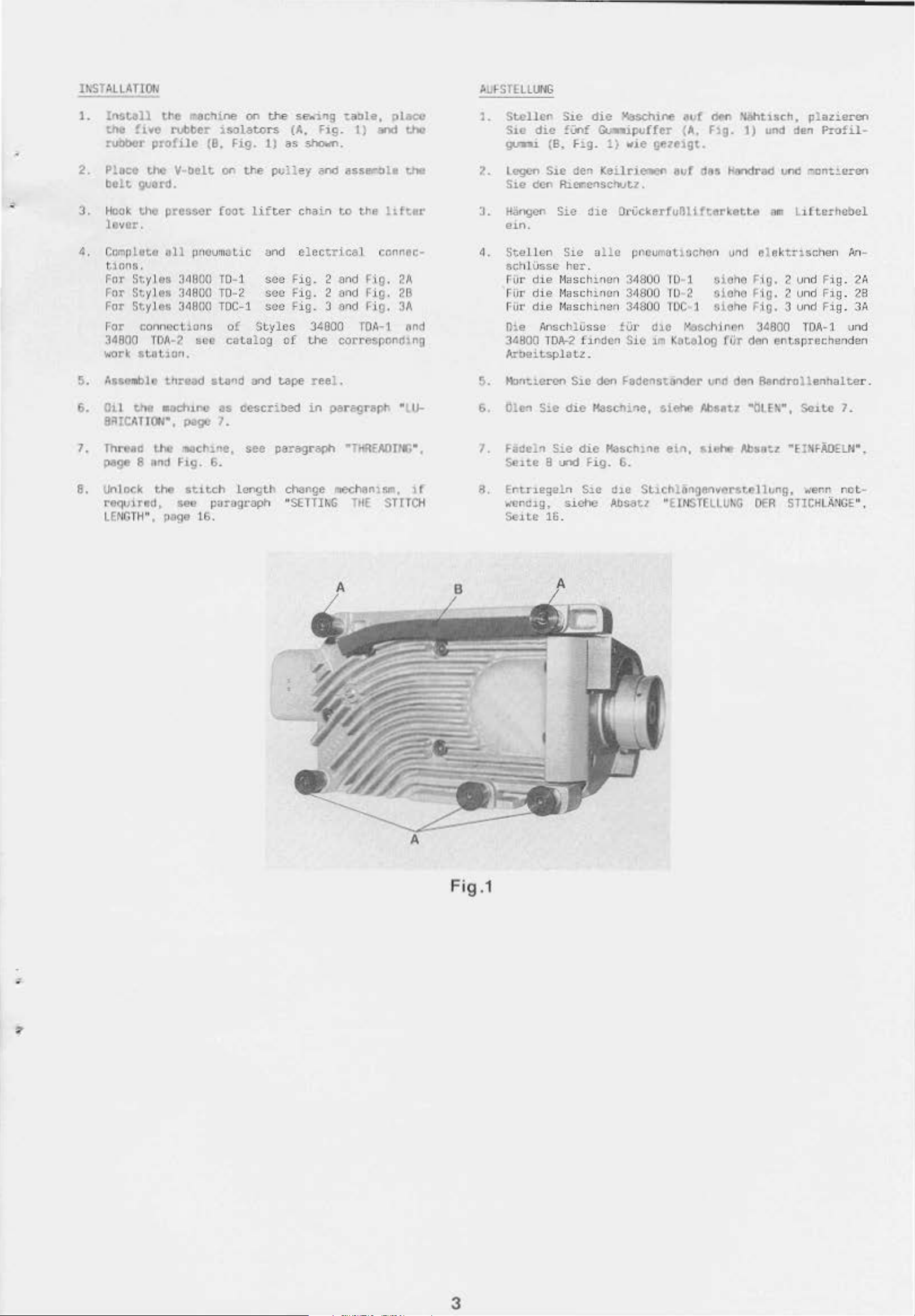
ALLATIOtl
1.
!nsull
tne
ruooor
2.
Plocc
belt
J.
Hook
lcvE:r,
the
"'8C.,ine on
!iwo
rubber
prof1le
the
V-belt
1solators
(6. Fig. 1)
on
guard.
the presser foot
the
the
po~~ey
lifter
se
{A,
••
••
nog
taole,
Fig.
sho<n.
and assP.t":Jle
cha
in
to
1)
the
place
:=tnd
llfter
tho
the
~L>STHLUt<G
1.
Stell~
S.te
~
2.
Lcgcn S1e den
s~e
3.
Har,gcn
tHn
.
Sic
die
!Unf
(B.
Fig. 1) wic
den
Rlerenschutz.
Sic
die
"".aschine
c..-ipuffer
K
eilri~n
die
Ot
at.~f
dM
'W'ItlSch,
(A, F1g.
gez~igt.
aof
dn,
l)
H~ad
UckerfuBlUterket.te
und
den
uno
am
ll.tterhabcl
plana:rcn
Profil-
c.ont~e=cn
4, CompLete
tlnns.
Fnr Stytos 3•9
For Styt
For
Styt
For
conncct1o
34800
~.
6.
•.o10rk
AsseMble
Oil
at.ot1on.
the
BR!CATJON•,
Threac
7,
pogo 8 nnd
6.
Unlock
required,
LENGTH
",
all
!JfiCum
0U
es
J•euo
os
3d9U<J
ns
TDAw2
sell
thread
•oc:tunc
pogo 7.
U10
-.ac~1ne,
F1g.
6.
the
stLtch
see pUr{lg.taph
pogo
t6
at.t
c and
T0-
1 sec F
TO-
< sec F
TOC-
1 sec
of
Style
cat.ulog
sLa~d
and
as
ocscribed
see
length
.
electrical
ig. 2 and
ig. 2 and
fig
. 3
and
s 34000
cf the correspond2no
tape
reel.
in
par~rept.
paragraph
ch3nge
"SETTir-.G
rnechanlsm,
r.onnccM
Fig. 2A
fig.
2B
Fig.
JA
TOA~1
•
·rHREAOnr,•.
THE
SHTCH
nnd
Uw
1f
tl.
Stellen
sch I Osse
Fur
die
rur
die 11aschinan 3'1SOO
Fur
die 11asch
Die Ansch1
Jasoo
At-beu.tsplatz .
!>.
t-\Jnt.tercn
6.
Olen Sic
7. Fadeln
Se1te a
a.
Entnegaln
-..·cr1thg,
Se.LtE 16.
Sie illle
he1·.
l•lasch
TDA--
2
Sic
die
Sic
und
siehc
P•lOuMOtiocnen und
inen
inen
ussc
f.J.
•
~dan
den
34000
3-1900 I
!La'
Sic
Fadcnstander
!U
1
oiohc
I U 2
OC l '11(1he F'i!J. 3 vnd
a1c
1rn Kotal
oioho
r--.aschinen
O!)
uno
Haschine, sieht'l Absat7
die
Maschine
Fig.
6.
SlC
d:lC St.lChlon.cJit'V(Irst.ellung,
Absatz "
ein,
siehe
EtNSTELLIJr,G
elektnsc:he
Fi!J. 2 vnd Fig .
Fi
0.
2 vnd
3~600
fUr
den
entsprechenden
den
Bandrollenhalte
""01
EN',
Absotz
OER
n
:.n
-
2A
Fig
. 2B
Fig. 3A
TOA
-1 und
r.
Se1U
~e:~FAD£LH•,
-..·er.n
STICH
'1
.
nOt.·
LANC£"
,
Fig
.1
3
Page 2
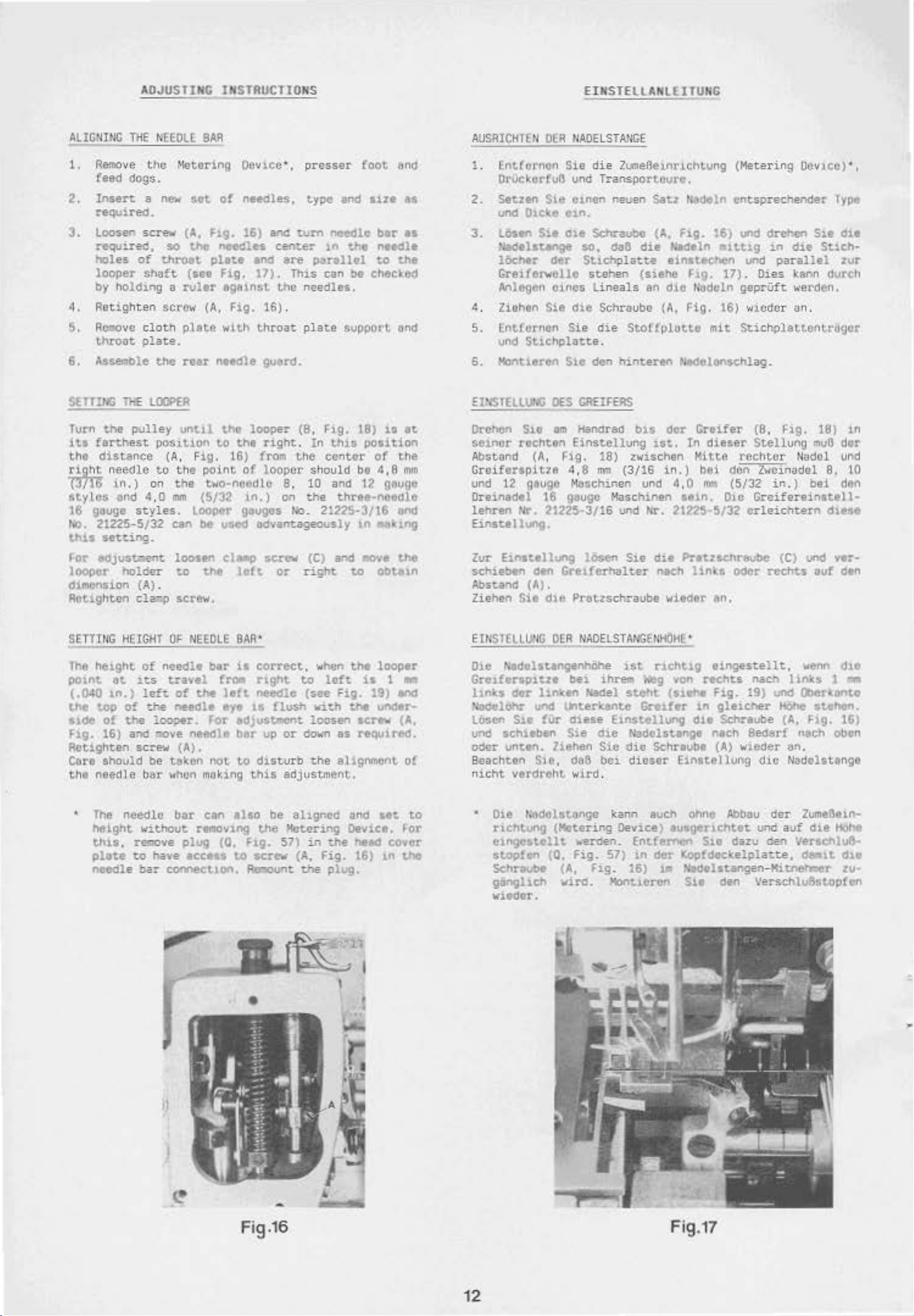
ADJUSTING INSTRUCTIONS
EINSTELLANL(lTUNC
ALIGIUNG
1.
2.
TilE •EEOLL
Refi'IOve
fee<i
dogs.
Insen
required.
3.
loosen
req..tirea,
holes
looper
by
hold~ng
4,
Retighten
5.
Rcaove clotl'l
throat
6.
A:Ssemble
SE
fliNG
Turn
its
the
~needle
p-[16
styles
16
No.
thl
For
looper
d1mcnsion
AOt.lghtan
1l!E
the
~lley
fa~hest
distance
in
.)
and
g~uge
styles.
21225-5/32
s
seu:ing
edjustaen~
holder
cl~
the
~lotering
a
new
set
screw
of
shoft
(A,
so
t.hcl
throet
(no
a
ruler
screw
plate
plate.
the
nu
LOOPER
unt~l
pos~t~on
(A. Flg.
to
the-
on
the
4,0
M
Looper
can
.
loosen
t.o
(A)
.
screw.
BAR
Oevi.ec•, pre-sser
of
needles,
Flg.
16) an.:!
needles
pllt.e
Fig.
and
17).
eg&inst tho
(A,
Fig.
with
t.hroat
net<lle guard.
tho
looper
to
the
right
16) from
point
(5/32
of
loop
t\riO•t'IOedlO
1n.)
gauges
be
used
od~antageously
cl.-p
the
left
cente!"
are
Thl.S
16) .
er
8,
on
No
screw
or
foot
type
and
wm
needlo
)..1"1
the
panllol
can
be
needles
plate
(8,
. In
the
.
support
~ig.
18)
th~$
canter
position
should be 4,8
10
and 12 g&uge
the
three-needle
.
21225-3/16
1n
(C) and
right.
.ov•
t.o
and
size
as
ber
u
needle
to
the
checked
ond
is
at
of
the
mm
ond
m~~1ng
the
obt.eln
AUSAJCHTEN
1.
F.nt(orncn
OlA
llAOELSTAilGE
Sie
die
OrUckorfuB und
2.
Setztn
und
J.
L05en
~elau.nge
lOchtr
Grei
SlC
01Cile
S1t
d~r
e1n.
o~e
ferwollc
e1ncn
Schraobe
so,
Stlchpla~te
stehen
Anlegen OJ.ncs
4.
Ziehen
5.
Lnt!ornen
und
6.
Hont1eren S1e
EINSTELLUNG
O.rehcn
se1nor
Sie
Sie
Sticl'lplaue
DES
Sio
em
rochttn
dle
den
CREIFERS
Handrsd
Einstellvng
Abst.ond (A, f'.'ig.
Graiferapi
ur.cl
12 gauge Masch1nan und
Dreinadel
lehren
Eil'ls
te
Zur
Einsttllung
schiebtn
Absta11d
Ziehen
tte
4,
8
16 gauge Maschinen
Nr.
21225·3/16
11
vng .
losen
den
Gret!er~alter
(A).
$).•
dle
Pratzschraube
ZU'IIe6e1nrichtung
Transportcvro.
neuen
Satz
(A.
cta6
die
einstechen
(siehe
lineals
Schraube
die
.
18)
nm
an
d:io ti.:Jdeln geprUft.
(A,
Stoffplotte
hin~eren
bl$
dor
1st.
Z\o'lschen
(3/16
in,)
und Nr. 21225·
Sie
die
nach
•<fitdltr
(Metering
~ldoln
Fig.
~eln
hg.
Fig. 16)
~~dolenschlag.
Greifer
In
Mitte
4,0
seln.
16)
•1tt19
17). Dies
mit
dieser
bei
den
1M!
(5/32
Ole
5/32
entsp
rec
und
d~en
~n
und
parallel
WlCdor
St.ichplattcnt..r;Jgcr
(8,
Stellung
rechtor
Zw-c1nadel
in.)
Greifereinsttll•
erleichtern
Pratzt.Chrevbe
lints
Oder
rechts
M.
Oe·occ)•,
hender
die
Type
S1t
St1ch·
41t
zur
kann
dvrch
~o~·erden.
~n.
l=lg.
18)
1n
mvO
dtr
Nodal
bei
8.
und
tO
dtt'l
d1tse
(C)
und
ver·
auf
d•n
SETTTUG
The
he1ght
po1nt
(.040
the
lldc
F1g.
at
1n.)
t.op
of
16)
Aotighten
Core
should
tht
needle ber
The
height
th1s,
plate
needle
HEIGHT
of
the: :
a~d
of
needle
.1~
left.
the
ooper.
ao~e
OF
NEEDLE
tra~el
of
the
needle
neeole
screw (A).
be
taken
when
m~king
needle
bar
con
wl.thout removing
r~ve
t.o
bar
plug
have
acuss
cornec-uon.
BAR•
bar
is
correct,
!rom
ror
not
l'"1S:"t
l•ft
needle
eye
1$
tdJuStmen~
bar
up
t.o
distur-b
this
also
the
(0,
f1g.
to
screw
~
when
to
(see
flush
vit.h
loosen
or
~·n
t.he alignment.
adjustment.
be
ahgr.Cd
"(ctoring
571
in
(A,
me
left
Hg.
as
and
Device.
the
Fig.
plug.
the
looper
is
1 -
19)
end
the
uncer-
1-crew
(A,
requ,red.
ot
att
~or
heAd
cover
16) 1n t.ho
to
Etr.'STCllUNG
OER
NAOELSTANGEIIHOHE•
Ole Nadolle.ngenhiihe
G:n:a.fvrspitze
l.ln\s
~loh.r
Losert
und
oder
der
S1t
sehuben
unttn.
Beaehten
nicht
verdr~ht
Oie
t..JdelstMge
richtung
eli'~CJIUillt-
s~fen
Sch:r&M.bt
gangllcl'l
bei
ihreto
llnken
HaCel
und l.)'lt.er1c:ente Gf'e1fer
!Ur
diese
Sie
die
Ziehen
Sie,
de6
S1C
bci
w1rd .
(Metering
werden.
CO.
fig.
(A,
fig
wird.
w1.edor.
ist
r1tht1g
Meg
steht
(Utht
Einstellunog
Nadclstange
die
Schra~bt
dieser
kanl'l
auch
Device)
Entfernen
57)
in
der
.
16)
1.1:1
Mont1ercn
eingestellt,
von
rechts
Fig.
1ft
dte
ntch
E1nstellung
ohne
ausg.enctrtet.
Su
Kopfdeckelplac~.
N»>elstangen
Su
n.ach
19)
gleiChef'
Schraube (A,
8ed8d
(A)
wieder
d1c
Abbau
una
dazu
- Kitnerwe.r
den 1/erschlu6stop!on
wenn
\inks 1 aa
und
Cbef'ltont.e
Hohe
F1g.
nach
an.
Nadel&ttngt
aer
Zume3e1.n·
auf
die
den
v.erscnlu6
dealt
St.ehtn.
<be
16)
obcn
HoM
d1e
zu
·
•
)I
•
Fig.16
12
Fig.17
Page 3
,
01.10
1
mm
<a:=
inCh
--t~r
Cf"eifef"
Right
Looper
th~
LEFT
t
he
machl"e
Needle
as
sc::cn
END
Jlld
of
fl'()m
R~hte
Cn~ifer
LINK
Ma:,.cl,ine
Right
Rechtc- N,)del
N1del
von
CN
SEt
~t<edle
der
TE
und
der
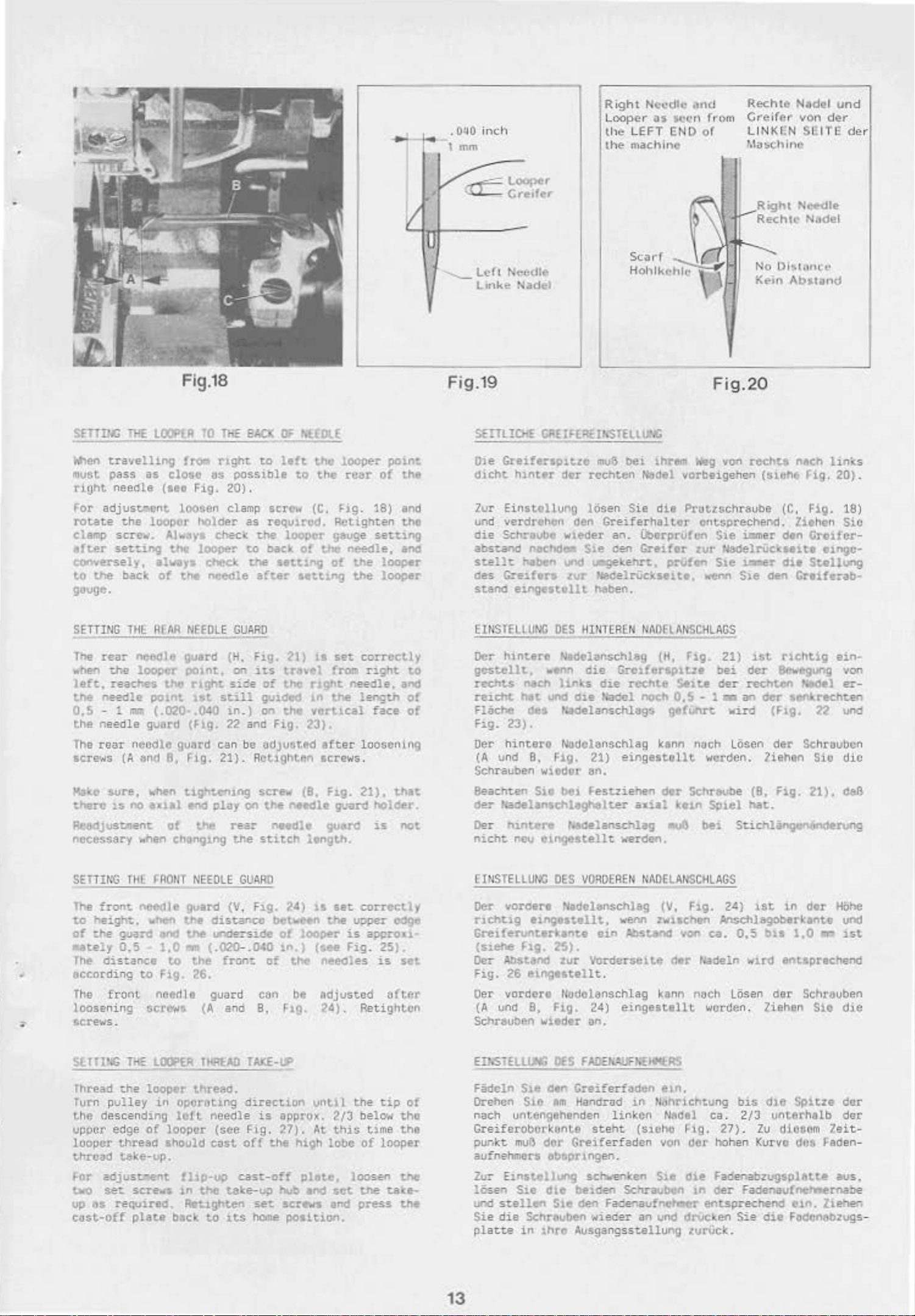
SfTIIM:
~en
must
right
for
rotate
clamp
e!ter
conve':"'Sely,
to
g<~uge.
TilE
t.ravelling
pass
needle
adjus~nt
the
scre~o•.
seuing
the
b.ack
Fig.18
lOOPlA
as
(ItO
loopor
always
of
10
ThE
froo-
r.tght
close
t'IS
Flg.
20).
Loosen clamp
holder
Alw,ys check t.he
the
lC)()Oe!"
ched:
the
t'ICedle
BI.Cl
OF
'HOLE
to
ldt
the
PO$Sible
as
to
the
screw
(C,
requ1rod. Retighten
looper
to
back.
of
the
sett1"9
aft.er
antv·.g
gauge
the
of
looper
rea:t
Hg.
needle,
Ute
the
point
of
tht
18) and
the
seuing
and
l()QC)er
looper
'-Left
Fig
Ltnke
.19
N<-f·dlf
Nadel
SE!Tl!DfE
Oie
Greifer101tze
<hcht
lur
und
die
hinter
Einstellung
verdrehen den
SchrDube
abst.a'ld n.echd, ... S1e
st.elh:
oe-s
stand
Mbcn
C!-e1fera
eingestellt.
Scad
Hohlk<·~
Cl!EIFERHI<STELLI>'.G
mu&
bei
thrtm
dor
rcehten
lQsen
Greiferhaltor
wu~der
.,.,
..-gekehrt.,
tur
~aadelrUckseu.e
h8~en.
Sie
an.
c~
Nadel
die
t:berprvh:n
Greifer
prvfen
No
Oi,tan~;.t•
Kein
Fig.20
fteg
vGfl
reehts
vorbeigehen
Protzsch:teube (C.
e-ntsprechend.
$1e iJimer den
t.ur-
Nade)rUclesntt
Ste
wenn
(s1eh6 Fig.
,i~r
Sle
den
du
Abs101nd
nacl'l hn.(.s
20).
Fig.
18)
Zithcn
S1C
GrollCr-
OlogC-
Stt~llung
Crnfuab-
SETTING
The
.nen
left,
the
0,5-
the
The
scre,.,s
Y•ll;e s.ure.
the"~
lHE
~[AR
rear
neeale
the
lOOP4.'r
reaches
ne-edle
:
po1nt
m~
(.020·.040
needle guord
rear
needle guftrd can
(A
and
when
1.$
no
aual
Re.o<IJust.ment.
ncce$sary •hen
SETTING
The
to
of
mately
The
eccording
The
loosening
screws
front.
height,
the
guard
0.5
distance
front.
.
THL
ne
....
to
:>Cff"l'i"".
fA014T
~le
~
and
1,0
ftg.
needle
NEEDLE
guard
,xunt.,
t.he
r1ght
ht
still
(Ftg.
8,
Hg
.
21).
t1gl"lten1ng
ertd
play
of
the
chan9~ng
NEEDLE
guard
the
distance
lhe
tn:te:-side
•
(.020--.040
to
the
front:
26.
guard
(A
ano
GUARD
(H.
F1g.
~1)
OJ"'
its
travel
siae
of
tho
gu1ded
in
. ) on
22
bo
on
rear
the
GUARO
(V. F1g.
th~
and
Fig,
ndJu6tftd
RCt19htftn screws.
scr-ew
t.he
(8.
ntedle
t'IHdle
stitch
24)
betw~eo
of
l
tn.) (see
of
tM
can
bt
B, Ftg.
is
set
fro:%1
rlght
1n
needle,
the
verttcal
23).
after
hg.
gu;ard
gu.el"d
ltng~.
a
set
the
upper
ooper
is
fig.
needles
adjusted
24).
correctly
right
length
face
t..O
and
of
of
loosco1n9
21).
thn
hOlcer.
is
not
correctly
e6ge
approu
25).
is
set
after
Retighten
tliiSTELLUNC
Der hint.ero Nadelanschl&g (H,
gestellt,
rechts
reicht
Hache
Fig.
23).
Oer
hint.ero
(A
und
$¢hrauben
Beacht.en
c:ler
r;adelan5chlegh8lter
Oer
h1nt.ere
nicht
ncu CU'Igestellt
EHISTELLUNC
oer
vordere
t'lehtig
·
Grelfel'\.lf'lterhntt~
(Sl.ehe
Ocr
Ab$t&na
Fig.
26
Oer vordore
(A
uno
Schrauben wieder
DES
••M
naeh
hnks
hit
und
oea
t.adelanschlogs
Nudclonschlag
B.
Fig.
wltdor
Sie
bel
Nedelanschlag
OES
NadOl81\$Ch)eg
eingostellt.
flg.
25).
zur
tnngutellt
lflldchnschlag
8.
Fig.
HH<TEREN
die
Grel!ert.QlUe
die
rccht.e
die
Plaodel
21)
eingestollt
en.
Festzienen
verden.
VOROEAEN
wenn zwisc:hon .JI.nsChhgoboerk•nte und
eJ.n
Ab:St.ancs
Vordcrsette
.
24)
eingestellt
on.
IMO
ELANSCillAGS
fig.
21)
bei
noc:h
ktnn
S.lte
0,5
gefUtlrt
der
- 1 •
wird
n-.ch Losen
wcrden. Ziehen
der
Sehraube
axial
ke1n
.u6
Sp1el
bei
IIADELANSCillAGS
(\!,
F1g.
24)
von
ca.
<ler rt.adeln
kann nach
LOsen
worden. Ziehen Sio
J.St
der
recht.en
an
dcr
(F1g. 22
der
(8.
Fig.
hat.
l"lChtig
~C90"9
Set'!\rechun
ein~
von
'.adel
er-
und
Schrouben
Sio
die
21),
daB
StichJanQnnonoerung
1St
in
dor
Hohe
0.5
bU
1,0
...-:
ut
wJ.rd
entsprechend
der
Schrauben
dle
EINSiElllH;
fhread
rurn
the
upper
looper
thrcbd
for
two
up
C~$t·off
~he
pulley
descending
edge
thread
t&ke-up,
ac!justl!leftt
set
sere...
3$
required.
plate
loo~r
in
oporating
loft
of
loOpQr
should
hlp-up
1n
Rtt1ghten
btck
threao.
needle
(see
cost
the
take-up
to
~ts
direcuon
is
~lg
.
off
the
cast:-off
set
home
vntl l the
appro~.
27).
high
huO
screws
At
plote.
and
2/3
th1S
lobe
$Ct.
and
posit1on.
tip
bela~
time
of
looper
loosen
the
take·
press
of
tho
the
the
the
Fadeln S1e den
Orehcn
nach untengthenden
Greiferoborkonte
punkt
aufnehmers
Zu=
E1n$t.ellung
lOsen
und
stelle-n
Sie
die
platte
13
OES
S10
am
muG
dOr
Db&prtngen.
S1e
dle
S1e den Faaenaufnel'mer
Schreuben
in
lhre
fAOEh.WfUEHiofHtS
Greiferfaden
Handrad
linkcn
steht
Greiferfaden
sct.-enken
beiden
Schrauben
eln.
in
N<thrtchtung
Nftdtl ca. 2
(sicho
von
S10
Fig. 27).
der
hohen Kur
die
Fader:abzugsplatte
'"
oer
entsprechend
wieaer
an
und
drueken
Ausgangsstellung zvrVck.
bis
dle
/3
unterhalb
Zu
vo
Spitze
diosom
dOS
der
dar
Zei
Faden-
aus,
Fadertaufnet.ernabe
e1n.
liehen
Sie
die
fodcnabzugs -
t-
Page 4
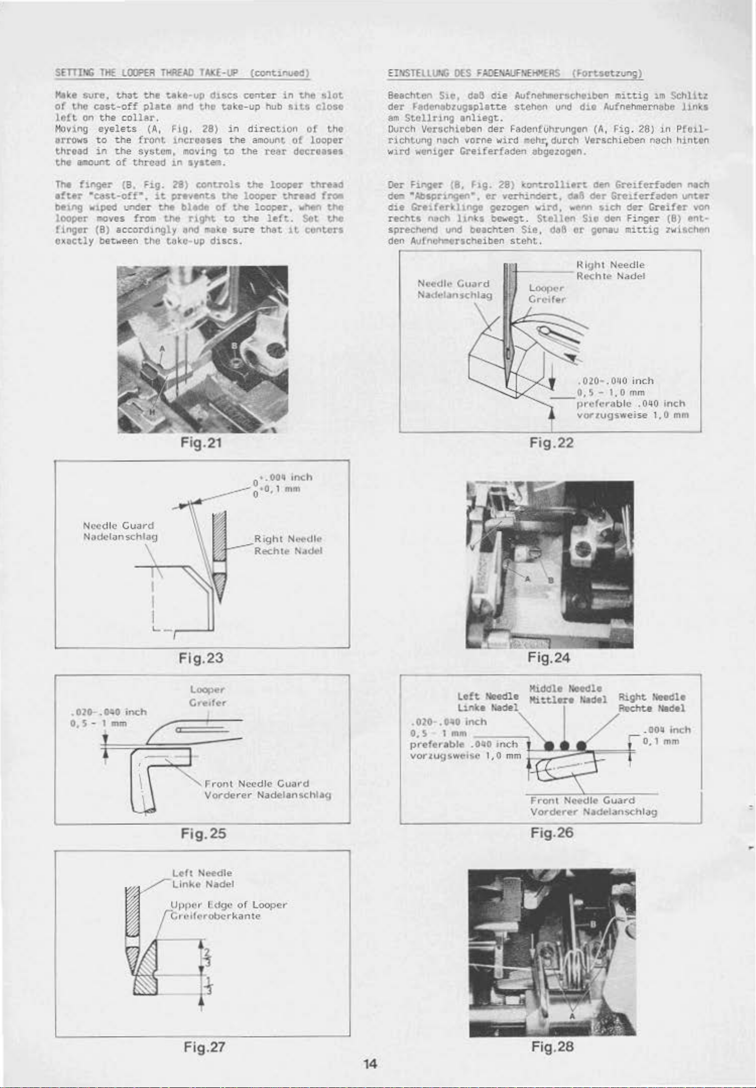
Kl~e
sure.
of
t.he
loft.
on
Hoving eyelets
arro
ws
throad
the
amount
tha~
cast-off
the
col
to
th
e
in
the
of
~he
plate
lar
.
(A
, FlO . 28)
front
system.
thread
ta~e~up
and
1nc;rooses
1n
d1ses
the
moving
aystem.
take
in
the
t.o
center
-up hub
direct
amoun
the
real'
in
the
slot
s:i U close
1on
of
t.
of
looper
doc;roases
t.he
EIHS
TELLIJhG
Beachten S1e, daB
der
~aelenabzugspla
am
St.cllring
IXS
F:.DEH:.UFHEI«ERS
anliegt.
Ovrch Vorachieben
richtu"g
wl.td "'on
nach
vorne
igor
Greiferfad~~
die
Aufnehmersehelben
tt.e
stehen
der
j:eelellfvhrungon
wird
•chr
, durch
abgez:o-gtn.
(Fortsetzung)
und
die
(A, Hg
Verschieben
mhtig
Aufnehmernebe
im
Schlitz
. 28) ir' P
nae
h hint-on
lin\:a
fcH-
The hnge-:-
e!t.tr
belng
looper
finger
oxoc;tly
·can-on•.
wtped
move
(B)
beo.-een
(8,
F1g.
under
s from
accord
the
:i.t
the
the
ingly
tu~o
28)
controls
prevtnt..s:
blade
r1gt'tt
bnd ma\e
up
discs.
Fig.21
of
the
to
the
loo;JGr
the
~he
sure
lOOpvr thrt-8d
thread
looper,
left.
that
•.
·o. 1
0
OOtl
when
1t
inch
mn'
Set
centers
froa
the
the
Oer
Ftngn
de.
•Abs,pr1ngen•.
die
Gre1fer1thnge
rechts
sprec
henCI
den
Avfno~rscheiben
nach
und
(8,
llnks
Fig.
bea
28)
~ontrollien
er
vcrhindert,
gezogen
be'o·egt..
chun
"[11-
n Rcch te
s
teht.
wird,
Stellen
Sie
---
,
418
wenn
da6
_0,5-
Fig.22
oen
Gre.t.ferfackrn nech
6er
Grel..fcrfaden
Slch
der
CHifer
Slo
den
Finger
or
genau
Hight
.
020-.01
prcferilb
vOf"zugsweise 1,0
mit.tig
Need
Nadel
10
1,0
lc .
le
inc
mm
h
OliO
unter
von
(B)
fil'lt~
zwisc-hen
inch
mm
Needle
Nndclanschlag
Gua
rd
.----------
.
02o-
.
~o
inch
0.
S - 1
mm
!
t
I
~
'--,---lJ
Flg.23
"""F
I
Vorderer
ront
-
--
Need
le Cuowd
Nadelanschii~J
-
Left
Linke
.020-
.OttO
0.
S 1 mm
pref
erable . 040
vonu
g!)wei:.c 1, 0 mm
inch
Needle
hade!
ir\Ch
Kl<ldle
Mlttlere
j::;
Front
Vorderer
needle
Nldel
Rl.ght
ReclTt.e Hadel
~:;:'!
Needle
Guard
Ne<!elansehl:.t9
Needle
'
Fig. 25
Left
Needle
CU
"OKC
Nadel
1
dgc
or
Looper
Fig.27
14
Fig.26
Fig.28
Page 5
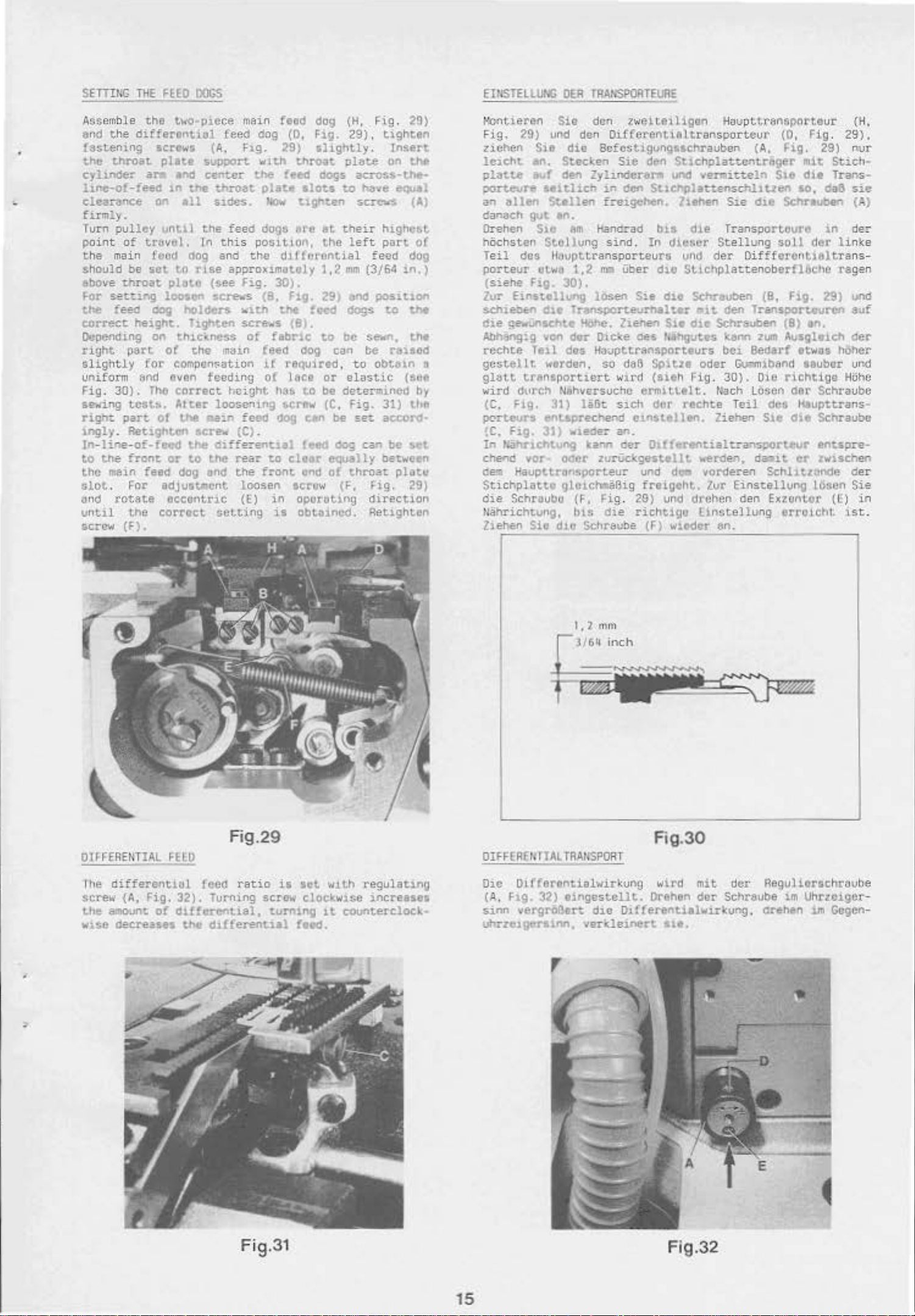
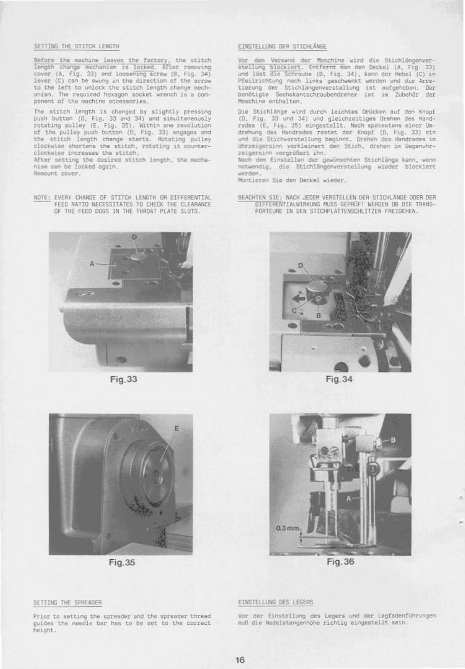
SETTI!.G
Tl<E
FEED
DOGS
ET!l$TELLUI.C
OER
TRANSPORTEURE
Assemb
end
•
fastening
the
cyhnder
llne-o!-feed
clearance
fumly.
Turn
point
the
should
above
For
the
correct
OVpending
ught
sli.ghtly
uniform
Fig
se-.dng
right:
1.ngly. Ret1.ghten
In-line-of-feed
to
the
slot
<md
untll
screw
le
the
throat
pulley
of
main
be
throat
setting
feed
part
.
30).
tcStt>.
part
the
fron~
main
.
!=or
rotate
the
(F).
the
t'WO·PJ.ece main
differonuol
seret~o·t
pllte
an
•l"'d
tn
the
C)('l
ell
untl.l
tr~vol.
feod
sot
dog
to
rise
pla~c
loosen
oog
holdeN
height.
on
for
&M
fhe
hghten
th1c<-ness
of
the
compen~ation
ovon
correct
Alter
ol
the
screw
the
or
to
feed
dOg
adjuttr.llflt
OCCOf'ltnc
eorTOct
feeo
(A,
F1..9.
•upport.
center
the
thzoat.
Sldes.
the
feed
In
this
posit1on,
and
the
approximat.oly
(see
fig. 30).
strews
with
scre-;.;s
of
m:u.n
feeding
height
loosen1ng
qm
feed
(C)
differenttal
the
rear
t~nd
the
loosen
{£)
:setting
feed
dog
(H,
dog
(0,
F1g.
29),
2'9)
llightly.
w1
th
throat
feed
plat.t
dogs
slots
~
tlghten
ere
dif f orential
plate
dogs
across-the~
to
have
screws
Bt
their
the
left
1.2
mm
{3/64
(8, F1g. 29) ane
t.he
feed
(8).
fabr1e
feed do9
1f
rtt<l\.drsd, w obta1.n ,
of
lace
ll:t&
to
!.Cr;tw
.,og c lrl'l
dOgS
to
be
c<Jn
or
elastic
be
determined
(C.
fig. 31)
be
set. accoreJ
te
.
f~
dog
can
to
cle4r
fron~
in
is
equally
Of'ld
ot
throat
screw {F,
oporot.1ng
obtnncd.
F\g. 29)
tlghten
Inc:ert.
on
the
eQUil
(A)
highct.t.
part
ot
feed
dog
in.)
position
to
tM
sewn,
the
rauod
(set
by
th&
be
s~t
bet~een
platu
Hg.
direction
Retighten
29)
1-:0l'ltieren
FJ.g,
29)
uehen
lcl.Cht
platte
port.evre
an
ellen
danaeh
Dr
ehen
hOchsten
Te
il
dos
porteur
(siehe
2vr
Ei,stellung
$chiebeorl
Cle
qe..:Unschle !iOhc.
Atlh'lng!.g
reehte
gcstellt
gla~t
wird
dvrc~
(C,
Fig.
..
pcort.eurs entaprecher>tl c1nst.ol
!C. FJ.g.
In
Mhneht.oog
chend vor-
ae!n
Haupttr(ln~porteur
Stichplatto
die
Sehr~ubc
uahrichtung,
Zlehen
Sio
den zweit.fntigen
und den
S1 o die
an.
avf
den
Scfcstlgongsschrauben
Stecken
Zyhndenu•
ae1thch
Stellen
got
en.
Sto
Bm
Handrad
Stc I lung
ll.:~opttran
otwu
1,2
ma
Fig.
30).
losen
Ole
TrltlSI)Orteurhalur
von
dor
Dleke
Tell
des
Ha~pttransporteurs
worden.
so
trftnsportiert
N8hvusuchc
31)
liBt
31)
v1.eder
karw1
Oder-
zurUckgestellt
glo1chaSBig
(F,
Hg
bts
Sio
die
SChraube
Houpttr&nsporteur
Oiffel'ent.i<runsporte
Sl.C
den
St1chplattcr"~tr&ger
unc2
ventieteln
1.n
den
Sucnplett.enschltt.teft
fre1.gehen.
sind
.
spo
rteurs
Uber
Sie
2ienen
oes
ll.ehen
bu
In
dic&er
un<J
d1o
S~ichplattenoberflOche
du
Slt
flodhg:~tes
Sie
dte
Transporteure
St.e
der
SChrovben
•1t
den
dl.t:
SCh=-eueen
konn
bCJ.
da3 Sc')ltze
w
1rd
(sieh
ermiu.elt.
s1.Ch
del"
oder
Fig
rechte
len.
.
30).
t(ach Loscn
Ziehen
an.
der
Dlfferentialcanspor-teur
1o"f!rden,
uod
de-
vorderen
die
freigeht.
.
29)
richtigo
(F)
und
wledtr....::•"c.·:._
Zur
drchen
linste1lung
ur
(0,
(A,
Hg.
mit
S1e
dl.l
10,
dte
Sd\rauben
llung
soU
Oiffferentloltra
(8,
F1g.
Transi)Ort.evretl
(8)
zurn
Ausgl•1ct1
Bedorf
etwas
lb""ITI:lband
Ole
richtigo
der
Teil
des
Heupttrans-
S1.e
dle
a.ar.u
er
Schhtlllncle
Einstellung
den
Exzontor
errc..lcht.
_ _ _
Fig.
29)
Stich-
Trans-
da8
in
der
ragen
29)
on.
hOher
ttuber
Schraubc
Sehraube
lf"'tspre-
zwl.schef"
lOsen
(C)
(H.
29).
nur
sie
(A)
der
linke
ns-
uno
auf
der
und
Hoh
der
Sie
in
tst.
c
.
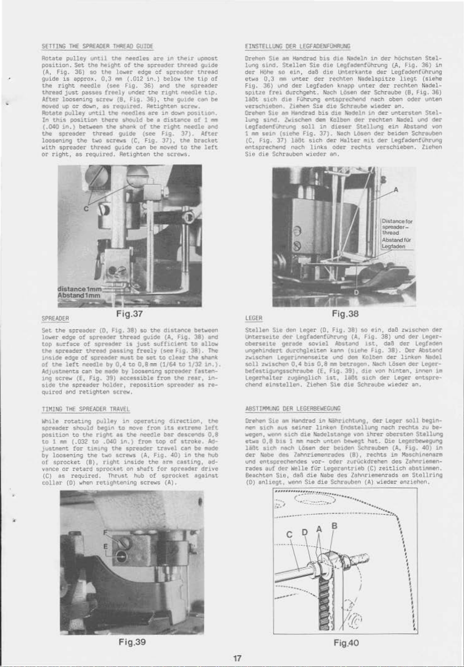
OIFFERE!HIAL
11le
differential
screw
the
vJ.se
{A.
Fig.
amoont
of
deCreases
FEE.O
feed
32).
Turning
differential,
the
d1!fereotial
Fig.29
ratio
screw
turn1ng
is
sot
clockwise
feod.
wJ.t.h
r e
increases
1t
countercloek-
gulating
01FF£R£t,
Ou~
(A
. F1g.
sJ.nn
TIAL
TRA"SPORT
Oiff'orontialwirkung
32)
e1n
vergroBtrt
uhrzelgertlnn.
gcstcllt.
die
01.fferenti1lwir~ung.
verkle1.nett
Fig.30
wl'l'd
Orehen
llt.
mit
der
dor
Scht&ube im
Regvlierschr~ube
drehtn
Uhrzciger
1m
-
Gcgen-
-
Fi
g.31
15
Fig.32
Page 6
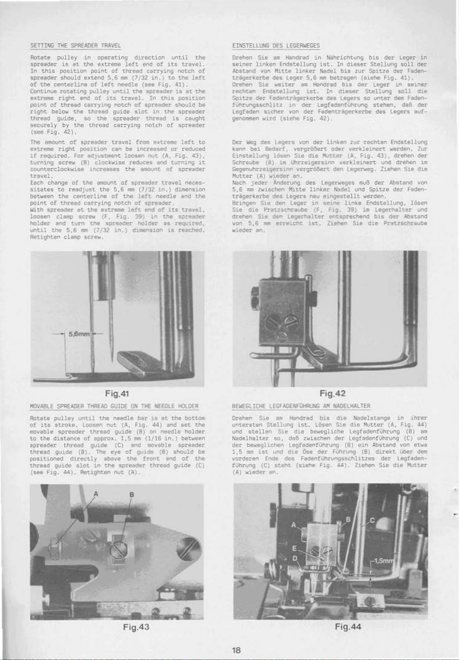
SUllhG
cover
lever
to
anilm.
ponent of'
Tho
pu$h
roteting
of
tht
cloc~wue
clocl!;wae
Alter
nls.
Aealount
tht
stitch
button
the
at\tCh
cen
THE
(A,
(C)
left
The
reQulred
the
pulley
pulley
shortens
tncreases
a.ctung
be
cover.
STITCH
LENGTH
33) and loosening •crew (8,
be
to
unlock
machine
length
(0,
(E. F1g.
push
length
the
locked
swung
Hg. 33
1n
the
hexagon
accessories.
is
c~ngod
;:md
button
change
the
stitch,
the
stitch.
c'e:sired
again.
the
d~rtction
stitch
length
socket
by
34)
and
35).
ll'ithin
(0,
Fig.
start&.
rot.ettng
stlteh
length,
slightly
!'e!IIOvlng
F1g.
34}
of
the
erro~
ch&nge
wrencll
~ch
lS
a com-
pressing
limultaneovsly
one
revolot1on
33) engages and
Aotat1ng
tt
count.er-
the
pulley
llteeha-
WIST£LLLN::
Vor
ct.
st•llung
U"'~d
lon
PfoilrlChtung
tierung
ben6tigte
DER
STIC>ti.NiGE
Yeruno
der
bloektert.
dte
SChraube (B.
nech
links
der
StlChlangcnverstellvng
Sechskantschraubendreher
Maachine enth81Lcn.
Oil)
StichHinge
(0.
Fig.
rades
drehung
und
d11
IJ\rze1ger~lnn
zelgtortlM
'i&ch
notwenthg,
..,.,..,..,_
HQnt1e~·n
33 vnd 34)
(E.
des
Stlchverstellung
dee
E.lnstellen
Sie
wird
rig.
35)
H&ndrades
vcrkleinert
vergro&en
die
Stichlingenverstellung
den
CLngcstellt.
De~kel
HtJschine
Entfernt
geschwenkt werden und
durch
un.d
gleichzeiti.gll
rastet
beginnt.
den
ihn.
der
gewUnsc:hten
wleder.
wire
.an
Fig.
34),
loichtes
Nlch
der
Stlch,
dle
Stlehlangenver-
den
Dec~el
~enn
der
(A,
Hebel
F~g.
die
1st. eufgchoben. Oer
ist
1m
ZubehOr
OrGcken
IPfitestens
Knopf
Or~cn
drehc!n
Stlehli:nge
au!
den Knopf
D"tehen
(0,
des
w~e<:1er
des
e~ner
Flg.
Hanarades
t.
Gegenuhr-
tann.
bloctiert.
(C)
33)
33)
in
Arre-
der
Hand·
Um
ein
ia
venn
·
NOTE:
-
LVERY
FEED
RATIO
OF
THE
CHANGE
FEEO
OF
r,ECESSITATES
ODGS
STITCH
Ill
THE
LEHGHt
TO
CllECK
THROAT
OR
DIFFERENTIAL
THE
CLEARANCE
PLATE
SLOT$
BEACHTEN
.
SIL:
NACH
JEOEM
OJFHRlNTIALWIRKUt\G
PORTCURE
lit
DEll
STIC><PLATTENSCU~ITZEN
VEASTEllfN
MUSS
GEPAOI
DlR
STICHLANGE
I
WLROEN
ODER
OB
DIE
TRAN$-
FREIGEHEN.
OEA
Fig.33
Fig.35
0,3
L">"'
•
Fig.34
Fig
.36
SETTING
Prlor
to
guides
THE
setting
the
needle
SPREADER
the
spreader
b81'
hb!l
to
bOd
tho apreader
bo
aot
to
the
thread
corre
ct
EINSTElLUMl
Vor
der
~B
die
height.
16
OES
lEGERS
rlnstellung
des
Ntdelst&ngcnhbhc
Lagers und
richtig
•1nge1ttllt
dtr'
Legfadenfl.ihrvngen
sein.
Page 7
SElliNG M
SI'R£ADER
TI<RUD
GUIDE
EIPIST!LU.t.C
DER
LEGUilEI.FIHIJPIG
Aotete
pos1tio.1.
(A,
guide
the
thread
After
_,..,ec
Aot.ete
In
(
.040
tl'le
loosemng
pulley
Set
Fig.
36)
is
approx.
right
just
ne~cdlc
passes
loosening screw (8,
up
or
down,
pulley
thlS
position
tn.)
between
spreader
the
with spreader
or
right,
as
unt1l
the
netght
so
the
0,3
(see
Creely under
115
until
there
the
thread
two
screws (C, F1g.
thte~d
requ
ired.
the
lower
ll"m
I"OQUJ
tJ'Io
guide
needles
of
the
( .
(}12 in. )
Fig. 36)
~19.
red.
needles
lhOuld
think
gu1de
can be
Retight
are
1n
spreader
edge
of
spreader
below
and
the
right
36),
the
Retighten
are
in
be a distance
o!
the
right
($ee
l=ig.
37),
moved
en
the
the1r
threed
t.hO
the
tJpreader
needle
gu1de con be
screw.
down
posu.ton.
o!
net(Jlt
37).
the
bucket
to
the
screws.
up.ost
guide
thread
tip
of
ttp.
1
ft'::
ond
After
left
Orehen
lung
dcr
etwtl
Fig.
spJ.tze
liBt
versehlOben.
Orehen
lung
S1.e
sl.l'loCI.
H6hc
0,3
36)
fre1
$1Ch
S10
atncl.
ftm
Stellen
so
ein,
mm
unter
und
der
durchgeht.
che
ltehen
• Handrad
lvlsehen
legfadenfutltvng
1 •
aein
(Slehe
(C,
Fig.
37)
1~6t
enuprechend
SJ.e
dle
Schreuben w1eder
noc::h
Handrad
Sic
daB
legfadcn
rUhrung
Sie
soll
Hg. 37).
sich
links
bis
che
dJ.e
l&gfldtnfUhruog
die
Lnterkttnte
der
rcchten
lo;
nl'!pp
Nach
LCSson
entsprochend
dio
Schreube
bis
dio
tktc:teln m
oet1 Kolben
in
diesor
t\ach
der
Helter
oder
An,
Nldtln
Nadelspitzc
unter
der
der
St.ellung
L~en
m1t
rechU
in
dar
l'lOeMten
(.A,
Fig.
36)
der
LegfadcnfVhrung
liegt
dar
rcchten
Schraubc
nach
oban
wiede=
rechun
oer
an.
unt.erston
Nadel unci
ein
der
beide.n Schrevben
der
LegfadenfUhrung
~tancl
(8,
oder
(litho
~l&d
Fig.
verschiebe.n. Z1ehcn
Spre<tdcr-
thN:~ad
Sttl·
in
tl·
36)
unt.en
Stel-
6tr
Yon
SPREA
DER
Set
the
spreader
lot..·er
top
..ne
1ns1de
of
edge
surface
spreader
et%e
the
lef
AdJVStaents
lM9
screw
a1de
the
spreader
quil'ed
TIHlNG
W\ile
spreader
positi()C"!
to
Justr.ent
by
of
vance
(C)
collar
and
THE
ro.-.at.ing
should
to
1 • (.032
!or
loosening
spro
cket
or
retard
as
required. Thrust
(0)
(0,
of
spreader
of
sp~adtr
t.hre3CI
of
spreader
t:
needle
can
be
(E,
Fig.
retighten
SPREADER
pulley
begln
the
r1ght
to
t1m1ng
the
(8),
sprocket
when
rct1ght.ening
Fig.
38)
tl'lre•d
i&
passu·~
aust
by
0,4
to
..
de
by
loosening
39)
fttcessible
holder,
reposition
screw.
TRAVEL
1n
to
"10VC
as
U1e
.0.:0
1n.)
the
spreader
t~ screw&
r1ght
1nside
on
so
the
gv1c:Se
just
sofflClent
freely
be
set
to
0.8
i7.li
(1/64
from
oper.t1.ng
fro-
needle
f~
toP
travel
(A..
F1.9. 40)
the
shaft
hub
for
of
screws
dutence
(A,
($ee
Flg.
clear
spread~r
the
bet.wucn
l=ig. 38) and
tO
38).
the
to
t/32
!esten-
rear,
spre6dCr
dl.reetion,
it.S
ex-tr.o
bar
de-scerlds
of
stroh.
can
be
in
tho
arm
c~sting, od~
spreader
sprocket
(A)
.
ngainst
1llow
shant
.111.).
ftl
left
miJdC
drive
The
1n-
re-
the
0,8
AtJ-
hub
LEGER
Stellen
unterseu.o
oberselte
ungehindert
zwischen
soll
$11
den
der
gerede
Cklrehglei~en
lf9Ct1nnenseice
:rvitchOn
0.4
Leger
Legfaa
soviel
bts
beftttlgung$$Chr8ube
Legerhalter
c::hend
tlnttellon,
ABST!M.UtiG
Drehen S1c
nen
s1Ch
vegen,
ewa
laBt
o'er
und
rades
""""
0,9
s1ch
ll~be
entspreehendes
uuf·
8eachten
(0)
an11cgt,
zuganglich
OER
LEGCRSEWEGU•lG
8111
Handrad
eus
seiner
s1ch
die
blS
1 •
nech
~Osen
des
Zahnriemenradcs
dor
Welle fUr
Sic, da6
wenn
Sie
ZlChen
nach
die
Fig
.38
(0,
Fig
. 39}
enf
Uhrung
(A,
Ab5tond
kaM
(uehe
unci
de.
0.8 M betrogcn.
(E,
Fig.
39),
ist.,
in
linkeP"'
Nadelstange
untet't
der
lo6t
Sie
die
1\i!lihnchtvng.
[nclttellung
von
bftwegt
be1dcn Schreuben (A. F1g.
(8).
vor-
odcr
zurUckdreh
legerant.rieb
t~abe
des
lohnriem
die
Schrouben
so
ei.n. daB
Fig.
38)
1st,
Fig.
kolben
''<M::h
dlC
von
tath
der
Schrt~ube
der
nach
ihrer
hat.
rechts
en
(C)
zeitlich
enrads
(A)
wi.eder
zwischen
und
da8
der
38).
der
linten
LOsen
hinten,
l.eger
...
ieder
Leger
rt:ehts
ober:sten
Die
Lege~
U.
H;)sChlntn.arm
des
.:.
anzichen.
dtr
der
teger-
tegfaden
Oer
AbSt.end
hedel
der
Logtor·
innen
Ufl
entspre·
an
.
soll
beginzu
be
..
Sttllung
40)
in
ZahnrieMtn·
abstimmtn.
Stollring
Fi
g.39
17
Fig.40
Page 8
S[TTING
THE
SPREADER
TRAVEL
ED<STELLUNG
DES
LEGERWEGES
Rotate
spreader
In
spreader
ot
COnunue
ext:re.e
potnt
rtght
thread
securely
(tsCO
The
extresMt
tf
turning
pulley
is
at
this
position
shOuld oxtend
the eenterl1ne
rot..at1ng
right
of
thread
below
gJJide,
Fig
.
amoont
rigl'rt
required.
screw
by
42)
ctnd
the
tho
.
of
spreader
posttton
For
(8)
count.orclockwise
t.ravel
Each
sitates
between
point
With
loosen
hOlder
untll
Retighten
.
change
to
readjust.
t he
of
threed
spreader
cla=p
and
the
5.6
clamp
of
centerline
et.
sc:rew
turn
.a
in
operating
the
extreme
point
ot
left
polley
of
tt.s
left
of
threod
5,6
~
needle C••• Fig.
untl.l
travel.
carry1ng notch
thread
so
thread carr
.CJUStaent
tnereases
tho
carrying
the
the
(7/32
scl"ew.
guide
the spr
eader
travel
can
be
loosen
cloetcwise
the
umoun~
the
5,6
of
of
the
notch
extreee
(F, Fig. 39)
spreader
1n.)
duoetion
end
of
eerrying
(7/32
the
ying
~n.)
spreader
In
of
spreaaer
slot
.in
throed
notch
froc~
e~ttreme
increased
nut
reduces
M\CI
a1110vnt
spreader
mm
(7/32 in. ) dime
lett.
of
left
needle
spreader.
end
of
1n
hOlder
dlJIIetlsion
until
its
to
41).
.a.s
thlS
should
the
is
of spr
or
(A,
Fig.
wrning
of
travel
its
~he
as
requued,
is
tho
traveL
notch
the
position
at
of
left
the
be
spreader
caught
eader
left
to
reduced
43),
it
spreader
neces-
nsion
and
the
uavel,
spre8<1er
reaChed.
Drehen
seiner
Abstand von
trigerketbe
Orehen
rechten
Sp1tze
fUnrungsschhu
Lcgfaden
ganommen
Oer
kaM
Einstellung
Schraube
Wag
bei
Sie
li*'k.On
Sie
der
des
M Handra<f
Endstellvng
Hltte
des
waiter
Endstellung
F~tr-&gcrkerbe
s~ch&r
wird
linker
Leger
tn
von
(Stoho
Legers von
Bed.trf, vergrO&ert
lMen
(8)
Sie
~
ltu'zeigeNinn
in
tlcihrichtvng
1$t.
Nodi)!
5,6
~
botregen
8l'll
Handred
ut.
In
du
der
tegfedel'\ful'\rung
der Fadentr&gerkerbe
Fi
g. 42}.
der
linktn
oder
die
flitter
In
bia
dieser
Legers
-verUeinen.
Gegenuhr-zetgerstnn vergrOBert den
Hutter
Nach Je<ter Andorung
5,6
tragerkerbe
Sring-en
Sie
dre:hen
von
W1CdCr
(A)
vtcdcr
m:a
ZWl!JChcn
Su
die
Prat.zsc:hraube
Sle
5,
6
I"'T'1
a~.
an.
Kitte
dos
lagers
den
Leger
den
Lege~lter
erreieht
des
linker
neu
in
(F,
ut.
Legerwegos
Nttdol und
eingostellt
sc.1.ne 1
Flg.
entsprec:hend
Z.uhen
dieaer
zur
(siehe
b1s
der
Stellvng
so
:.r:ur
rechten
verkleinert
(A,
Fig
Lege~eg
muB
werden.
inke
39)
i.e Lege.rttelt.er unci
Sie
blS
dor
L.oger
Stellvng
Spittc
Leger
soll
dor
F~g.
41).
~n
aoll
voter
stehen,
des
d•
daB
legert
Endstlllung
wr<ltn.
. •
3),
drehfn
und
drehon
.
Ziehen
der
Ab&tltnd von
Spitze
dcr
End.stellung,
bis
der
die
Pratucnraube
in
der
Faden-
Hiner
die
Fecen-
oer
euf-
lur
oer
1A
Ste
dte
~eden·
lbsen
Absund
IIOVABI.E
Rotate
of
movable
to
spreader
thread
its
the
SPREADER
pulley
stroke
spreader
di s
guide
positioned
tnread
(see
gu1de
Hg.
until
. Loosen
tance
thread
(8).
ducetly
$lOt
44).
Fig.41
THREAD
the
nut
thread
oC
epprox.
guide
The
above
1.n
the
Rttigh<t.en
GUIDE
needle
(A,
guide
1,5
(C)
eye
of
the
spreader
~
ON
Ftg.
(8)
mm
and
guide
(A).
THE
ber
NEWLE
1•
at
the
44) end set.
on
needle
(1/16
in.)
aoveble
(8)
fr011t end
thread
HOlDER
bott.OCI
holder
between
spreader
should
of
guide
the
be
the
CC)
8EIEGL1CHE
Drehen S1e
untersten
und
stellen
Nadelhalter
der
beweghchcn
1,
5
.m
vorc!eren
fUhnJng
(A)
'Wieder
Stellung
ist
Ende
CC)
Fig.42
LEGI'ADEh~i)R)loG
o~
Handrad
ut
Slo
die
flO, dt16
zwischen
Logfadenfi.ihrung
und
die
Ose
des
FadenfUtuvngsschl.lttes
$t.eht
~
{siehe
.
A1C
liAOE~
bis
dte
N&dclstange 1n
.
lOsen
Sie
<fie
"'-'ttcr
ber.reghche LegfedonfVhrung (8)
dor
Legfadenflihrung (C)
(8)
c.1n
der
Fig.
F\ihrung
44).
(8)
Z.1.ehen
(A,
Fig.
Abstand von
direkt
der
Sie
uber
Leg(eden~
dle
ihrer
44)
am
und
etva
dem
~tter
•
Fig.
43
18
Fig.44
Page 9
IIEFOLE
Set.
clou
the
•
ano
threM
•tJhCI\
sere"'
04EC<lNJ
HOLDER
the
needle
as
ne.dle
Itt
the
guide
Lhe
(E).
THREAD
hOlder
posstble
thre~~s.
threao
{0)
needle
OF
iHE
SPR
GUIOE
to
For
gutdc
clears
l)flr
AOER
t.hread
the
neecnea
adJuSu.tnt
O$
requ\rtd.
sprcarltr
rnoves
up
S::TTH~
guide
end
(0.
Ftg.
44)
vtth<>ut
p\nchr'!;
l00$en screw (E)
~~ke
5ure
th~t
thrcud
do•...rn,
guide
A~ttghten
as
(C)
FAO(NFiJHRUt>.G
Stellen
Cll.Cht w1e
tl.ngekle-t
Fadcnfvhrung
dt16
dte
enschliJSt.,
Sie
dtC
PRUFlH
OEA
AM
NAOELHAL!!!
S1e
die
Fadcnfuhrong (0.
qllch
werden.
ttltsptecheno
~adentUhrung
wenn
sc-nnube
LEGEREINSTflL~~
tu
den
Meh
(0)
dtC
Nlu'Utlltangc
(E)
"lAdftr an.
Ftg.
Nadeln.
l&sen
n1.cht an
der
gc:>tellt
44}
1m
OhM
C:•6
SC:hnvbc
\rro'tr<l•n,
Cler
legfodcnfVhrung
3uf
\Jnd ab
~~delh<er
'dte
t.:adtlhdcn
(E)
kiM
be~chten
gcht
, l1ehe:n
so
dl.c
SlC,
{C)
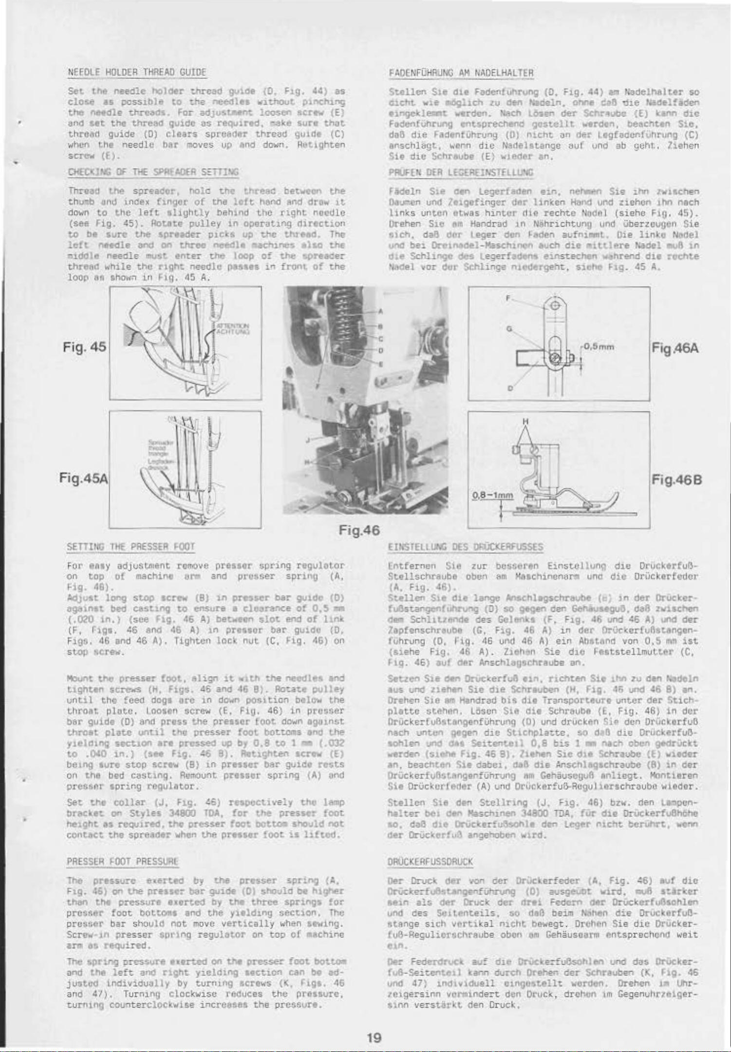
Thread
thu-.b dnd ln(fex fi.ngor
down
(see
to
left
-
tddltt
thrend
loop
to
Fig.
bt
t'IIHdle
8&
the
the
45}.
sure
needle
..
·hile
shmi.,
spreador,
left
AotltO
the
sprnder
and
on
must
the
nght
in
f.ig,
Fig.45
r
'Iii•·
·-
..-
-
•
Fig.45A
hole
of
shyht.ly
pulley
three
enter
noodle
dS A.
q&,
''
'r:.
\1;
t
h l
.
the
thre.ac
the
left
hehlnd
in
oporutl.ng
ptets
t.he loop
nef!dlt
up
:Nclune$
peues
~
I
.~
.G"'ItH'V'•
~~oc•u
...
hand
ttle
the
of
i.,
I
bet·HeOt'l
Alld
drow 11.
1
•ight
the
front
nacdlc
rlir•ct1on
th:~ed.
•lao
sp~aGer
ot
the
The
the
the
Fadeln St.e
Oau-.en
links
Orehen
sic!'\,
IJnd
bei
d1e
Schlinge
'1.-ldel
•
•
cen
legerflotn
unci
ltlgefinger
untcn
daB
vor
etwas
Stc
nfll
cor
Drcuudel-K=schtnt>n
dur
hinter
Handrad l n
Leger den l-aden aufnilfl'llt.. Die
des
legerfaden$
Schlinge
etn.
d&r
hnken
rli.e
rechte
Nllhrichtuno
avch
etnsteclwn
motlergel"'t,
F
f~
G
D
H
rtehl'llttt'l
Hand
Wi<JI'll
die
eu.t
sieM
Sie
thn
tw-lac.he:"l
und
ziehun
(s
iehe
und Uberzouuen
.thn
FLQ. 45}.
linkc
lere
...
..,hrend
f..tg.
f.adel
45
die
A.
-.u8
reehte
Fig.46A
Fig.46B
nach
Sie
N&Ciel
in
SETTING
FOI"
on
"9·
AdJvlt
ag~unat
(.020
(F,
Flgc.
stop
Moorlt
tisnttn
until
t.hroat
b81"
t.hro.tt
ytelcnng
t.O
betng
on
prec•ttll"
set
b1"3Cket
hetght
contect
1HE
eaay
odju$ttnent
top
of
46).
long
bed
1n.)
r1g1.
46
and
~cre~o~
the:
presser
screws (h,
the
plate
guide
.040
the
t.M•
(0} and
plato
sect.ton
1n.)
sure
bed
&p
rir.g
collar
on
u rcqut'f"ed,
the
PRESSER
machino
StoP
eastt.nv
(see
fig.
~6
and
46
A).
.
fceCI
dogs
. 1
oosen
until
($ee
stop
scrt·., (8)
casting,
regulator.
(J.
Styles.
spread•r
FOOT
sere•
46
foot,
F1gs.
prus
thO
•r•
Fi!f.
34800
the
remOve
um
(8)
to
ensure
46
A)
A)
TightC
il
align
45 and 46
urc
in
r.ere·..,
t.he
presser
pru~
~
1n
RemOunt
Fig.
'6>
TOA.
oresser
when
the
pressor
and
in
prusser
preuer
spdng
sprioo
bar
• cloot"8nce
bet-etn
1n
preuct
lock
it
do·.,n
(E,
pressor
up
8).
pressor
prtuot
r~SPI!Ctively
pressor
~lot
nut
Ol'lth
8).
position
Fi!J. 46}
foot
toot.
by
0.8
A9ttShten
!or
the
!oot
DOttoll
end
bar
(C,
Hg,
the'
needlct
Ao~ate
dawn
bOUOI'IIs
to
bar
guide
spring
presser
loot
regulot.or
(A,
gu1de
of
QU1d0
0.$
of
(0)
11nk
{0,
46)
and
pulley
below
in
1 •
scrtw
the
prcGser
ogt~1nr.t
eno
\.he
(.032
(E}
rests
(A)
unci
t.ho lamp
loot
snould
is
not
llftod.
Fig.
:':'fl
on
46
EUl$1El~Ut.t
Entfe
rnen
StellschratJbO
(A.
Hg.
Stell~
fu6star:genful'lru!'11Q (0}
dem
Sc~lltl~
7apfensctweube (G,
f\ihrun9
(siehe
f.ig.
46}
S.tzen
1us
und
Orehen
platte
Drikk.erfvBstangenfUhrung
nach
untcn
aohlen
..
eroen
an, beacht&n
OrUcl:.erfu6sungenfUn.rung
$ie
O
rUcl:.
Stellen
1\iilt-er
so.
da6
der
OrUc~erfu-1
DES
Sht
46).
Ste
die
(0,
Fig,
auf
Sie
~..,..
ziehen
S1e
"~
stencn.
gegen
und
c:MI
(SleM
crJftdtr
Sie
be1
de-n
d1e
rig
46
der
Handrud
hg.
Sie
d•n
Or'uci(erfu!hohle
lll'iiO<ERFUSSES
zur
tJcsseren
obc"'
ttm
lange
des
$0
Gclen~s
FJ.g.
.
46
ur'\d
A) . Z1eMn
Haachincnal"''' unc
Ansehlagschrevbe
gtgen
46
46
A)
Einstcllvnq
Ger.
(F, F1g.
A}
in
ein
Si
e d1C
Ans.chhgschraube
Orveterfu8
Sic
d1e Schreubun (H,
LOscn
d1.e
Seitentet:
46
dabc1,
(A) und Ot(ickerfuO-Rcgu)
S~cllrlng
l<asch~nen
ange-,oben
un,
bi~
d1e
Sie
oio
(0)
ur.d
Suchplat.te.
0,8
B}.
ltehen
dl3
die
em
CehauscouA
{J.
34800
den
wu·d
nehten
lran~cortture
Schraube (E, Fig.
drucken
bis
SJ.C
Anschltgachra~c
Ftg.
TOll.,
le-gtr
.
"
d1e
die
Or-iickertcdcr
(
ln
der
Gehauugu5.
46
der
OrVc<arfu6sungen-
AMtMd
l=eststellmut.ter
an.
Sio
rt.;.
Sie
so
d.;ol)
1 • '\ac.h Gben
cht
Schraubc
snhegt.
htrs
46)
fur
die
n-.cht
de8
und
~6
von
thn
:zu
46
und
unter
den
die
chrau
bzt~~·.
OrUelr:ertuOhohc
benJhrt,
Orucktrfufl·
Orucker
zvischen
A)
und
der
0.~
11m
ist
(C,
Cen
~deln
46
8)
an.
der
Stic~·
46}
in
dcx
Oriickerfu6
Orucl<erfuB·
9fdrVc:kt
(E)
w-1eder
(8}
in
der
Hontieren
bc
wieder.
(len l.l:llpcn-
wnn
·
PRESSER
The
Ft.g. 46)
than
presser
presser
Sere..-·
crm
The spr1ng
and t!'le
justcd
and 47). Tur
turnlng
~OOT
PRESSURl
Pl"tnurc
or
the
foot
bar should
)n
pre
a~
required.
left
exerted
the
pressc:-
pres$ure
bottoms and
sser
pressure
and
exerted
not
spring
exex-..e<t
r1sht
1ndiviouully
nli'I!J
clock
countarcloc~wise
by t.he pros!.>e:t
OOr
guiM
Oy
the
move
regul8t.or
on th4t
y1.elding
(0)
th•
three
yleldtno
vfJrt1cally
on
pre.sser
section
spring
:.ihOuld
be higher"
springs
section,
.,,hen St'Hing.
too
of
foot
can
CA.
tor
The
machine
botc.o-
be
ad·
by turn.tng screws (K, F'l.gs. 46
wise raauce&
incrcasftt
the
the
pre
preasvrc,
ssure.
OROC<ERFUSSDRUCK
Oer
OrUckedoB$tllftgl11flir.rong
flein
und
Rtange sich
{ui}-Regulierschrauhe
otn.
Oer
(tJB-Seitf!f"'t
und
/Olgersinn vortnindert den Druck,
tunn
19
Drucll.
ces
als
Scltenteil
df!'r
~r Druck
vortika
Fedcrt!nJCc
..
cn
I
47)
inchvtduell
verstiit•ltt.
YOI'I
au:
kaiVI
den
dcr
Oruclerfcder
(0}
der
dr•t
s,
$0
daB
l
ntellt
obon
dte
durch
bewegt . OrchM
el'l
OrUc:ke:-fu&ohlen
O'rehen
etngiJ.$tellt
Druck.
(A,
avsge\.IOt
Fedcrn
beim
dftr
NGI'Ien
Gehauscarm
der
Scf'lrauben (K, fl.g.
\oiCrdctn.
drchun
Fig,
~6)
•uf
v1rd.
IIIUft
tt.arlc.cr
OrUckerfuAtohlen
di:e
Or'VCI:.ertvB-
Sie
die
OrUcke
ent
sprech
vod
Orehen llll
tm
Gegenuhr~eiger
das
cnCI
OrUcke:--
die
r-
weit
46
lt'lr-
Page 10
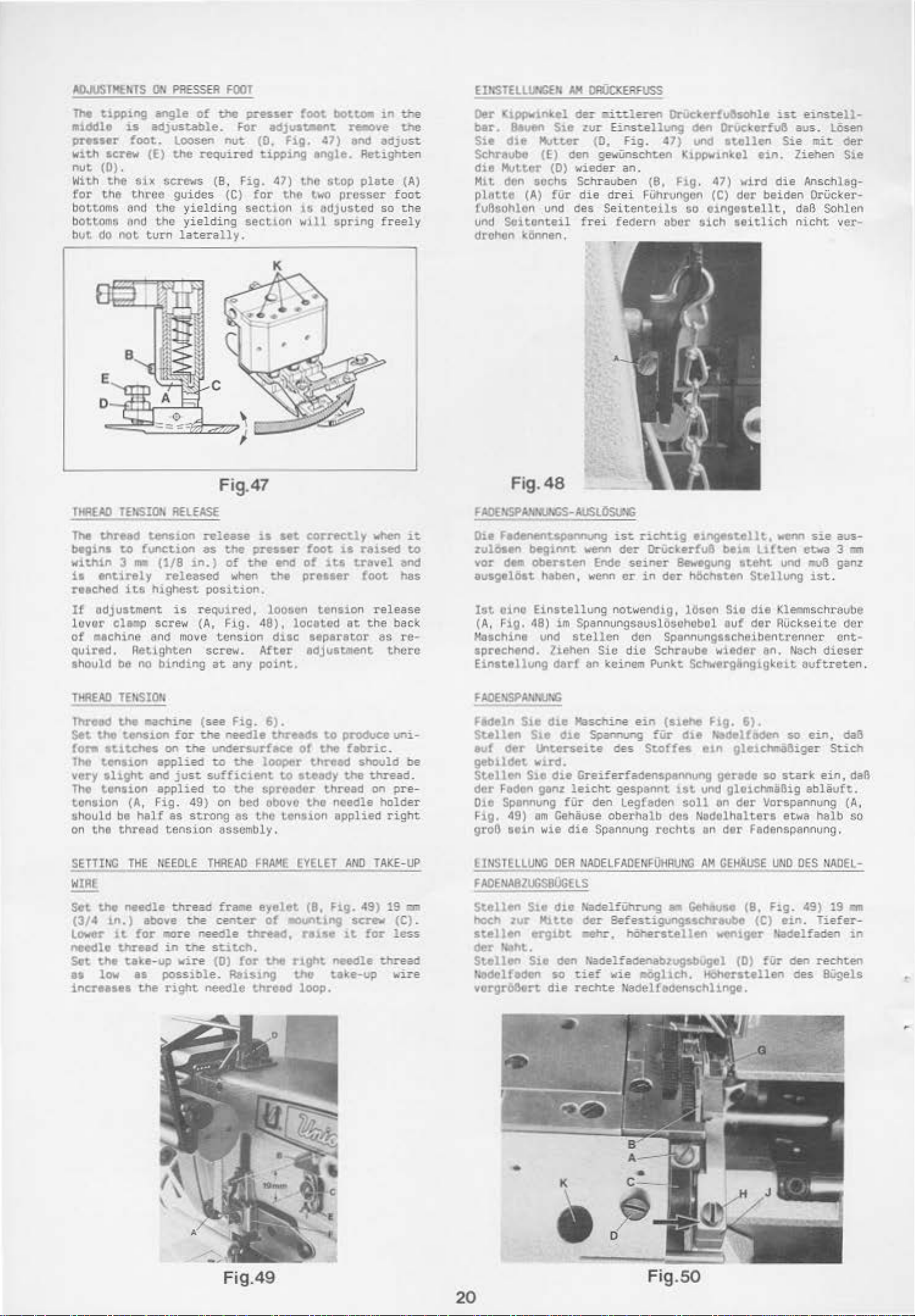
AIWSII!EHTS
The
t.lpping
•1ddle
preuer
OH
angle
is
adjust.eble.
foot.
w1th screw (E)
nut
(0)
.
With
the
SlX screws (B. F
for
the
three
bottom
bot
but
~
and
toms Md
do
not
tho
the
turn
PRIOSS
of
Loosen
the
required
guides
yielding
yielding
latera
EA
fOOT
the
nut
(C)
lly
presser
For
(0,
tipp1ng
ig.
for
section
section
toot
bot.~
adj~o~stiMI'It.
Fig.
re-cwe
47) and
angle. Retighten
47)
thO
stop
the
two
prosser
is
OdJ
usted
will spri
.
.1n
the
the
adjus"t
plate (A)
foot
so
the
ng
freely
ElHST'ELLI.r(i(H
Oer K
ippwtnhl
ber.
Sie
SchraubO
dte
Mi.t
pl
unci
8auen S1e zur EirtSt.ellong
d'-O Mutter
(E)
Mutter
dan
&tte
fvBuohlon
sochs
(A)
(0)
fUr
und
Soitonteil
drohon konnen .
AA
{)Fij(xEfiFUSS
der
aiuleren
(0,
fig.
Or\tc:t.erfu&sohle
cSen
OrUc:t.erfuB
47)
und
stollen
den gewUnschten Kippwint(el
wieder
Schrauben
die
des
frei
an.
drei
Seiten
fe<Ser
(8,
Fig
.
47)
FUhrungcn (C)
teilG
•'
t'lber
GO
oingestell
#ich
wird
dor
seitlich nic
ist.
Sie
ein.
die
beiden
t .
einst.ell-
aus.
LOsen
mit
Ziehen
Anschtag-
OrUcker-
daB
Sohlcn
ht
oer
Sie
ver-
THAEAD
Tht
begins
within 3 ""'
is
roached
If
lovor
of
quir~
should
TlflEAO
Thread
Set
!or.
Tho
very
Tho
tension
$hOuld be
on
!Eh'SIOH
thread
tO
function
entirely
its
adjustment
clup
..
chine end
.
Retighten
be no
TEI<$!01.
the
the
t.enston
stu:.ches
tension
slight
tension
(A,
half
the
thre
RELEASE
tens1.on
{1/8
released
highest
is
screw (
move
binding
.achine
for
on
applied
and
just
applied
Fig.
as strong
ad
tension
Fig.47
release
as
the
pnsur
1-n.)
of
the
when
position.
req
uired,
A,
Fig.
tension
screw.
at
any
(
see
fig
.
the
needle
W e
undersurface
to
Che
sufficient
to
the
49
) on bed obovo
as
assembly.
is
Ht
correctly
foot
and
of
its
the
preuer
loosen tension
48),
located at
due
After
ttpar&tor
edjuttme
point.
6).
thl'e*'s
looper
t.o
spreedor
to
of
the
t.hroad
steady
thread
tho
tho
tension applied
when
it
it
reued
travel
foot
to
end
has
release
the
back
es
re·
nt
there
produce
fabric
the
uni-
.
should
thr
ead.
on p
be
re-
needle holder
right
Fig.48
FAOENSPA.,M.JhCS-AUSLi!Su<G
Die F*'tnont.sP&I'W'tt.lng
zul6sen
vor
ausgelo1t
1st
(A
, Fig.
Kaichine vnd
&preehend.
Einstellvng
Fecseln
Stellen
evf
geb1ldot
Stellen
der
~1Mt
dM
Obersten Endc
h&ben, wenn
oino
Einstel
48)
im Spannungs.au
stellen den
liehen
derf
S1e d1e Maschine
Ste
d1e Sp.aln.Jng
Cler
li'tt.erseit.e
vud
.
Sie
die Crei!erfaden
Foden ganz
leic
010 Spannung fUr den Legfaden
Fig.
49)
am
Cehause
groll
tein wie
die
ist.
wenn
der
seiner
cr
lung
notwe
Sic
die
an
kein
em
C'es
ht
gespannt
oberh8lb
S~nnung
ri
chtig
Drl.ict.erfu8
in
der
ndig
slosuho
Spann
Schraube witt<ler
Punkt Sehwergdng1gke1t
ein
(siehe
fUr
Steffes
spennung gorade
rccht-a
e1ngest.ellt,
bei•
Bewegung
tteht
!Wehsten
,
l~son
bol
Sie
out
ungascheibe
F1g.
6).
d1e h"edelt&dcn
e1n gle1chltla6iger
ist
und
gloichmaBig
soll
on
der Vorspa
des
Nodolhalt·
an
der
wew~
sie
lHten
Stellung
die
der
ctwa 3
und
o.vB
J.St
.
Klemmschraube
AUc
kse
ite dcr
ntrenncr
an.
NaC-h
dicser
ouft
reten
so
ein,
St.ich
so
stark
ein
ablSuft..
nnung
ers
etwa
halb
Fec!enspannvng.
aus-
11111
ganz
cnt-
.
daB
,daB
(A,
so
SETTING
WIRE
Set
the
(3/4
1n.)
Lower
ncectlo
SOt
the
11
low
inr:rtues
THE
>IEEOLE TlflEAO
needle
thread
above
lt
for
.,re
thread
in
t.lke-up vire
as
possible
the
right
t.he
r.eedle
tne
fredle
center
threed,
st.itch.
(0)
for
FRAME
eyelet (8,
EYELET
of
.,.,_.,Llng screw (C) .
nue
thO
r1ght
. Rel$1"9 t.ho t.ake-up
needle
thrHd
loop.
AND TAKE-
Fig.
49)
1t
for
needle
UP
19
o:.m
less
thread
wire
EINSIELLUNC
fADENA82UGSB0GELS
SteUen
hod'l
zur
stellen
oer
ltaht.
St.ellen
U3delfadon
vcrgrOOort
OEA
Ste
d1e Hadel!
Mlttc
erg.tbt
S1e den
so
die
NAOELFADE•~iiHAIJ..U
der
-ehr.
~-del
tief
rechte
•
AM
GEHAUSE
Uhn.Jng
• Geheuse
(8,
Sefestigungssc:hreubc
hOherstellen
fadenabzugsbugel
wie IIOgllch.
wentger Hadelfaden
(0)
Hbherstellen des
Nadelf&den$Chllnge.
000
Fig
.
(C)
ein. Tiefer-
fUr
den
DES
49)
rechten
UAOEL-
19 •
in
Bi.igels
Fig.49
20
Fig.SO
Page 11
StTll~
THE
EYELET
St-t
t1'1f!
hetght
(F, f
Lht~ftd
of(
for
$01.
the
botwoen
1.9
. 49)
for
eyelet
1'1
t1ghter
5preader
aprc&dtr
eyelet
SPREADER
of
to
an
exact
for
a
looser
spreader
thread
threed
(E) end
THRE:.O
spreader
have
pull
stitch
spreader
thread.
frame
forms a
pull-off
FAA".E
EYELET
tl'lteld
eo-oft'
forMation.
thrtod
eyelet
(F,
hort:ontal
tytltt
A'J>
oull-off
Just
s.ufhc~cnt
Ratse
and
Fig.
49)
straight
(F) .
PULL-OFF
eyelet
the
pull-
lower
so
th~t
lina
~t
Stollen
HOh~
LUf
der
ctnen
$1e
d1e
ao
tnn,
81\0ung
einer
Ab7ugsf\.ihrung
atraffer
t-'.Onueren Si.e
so,
doB
der
Abzuys!uhrung
legfaden
daB
geraCe
ex~kten
ergibt
angezogenen
die
L
egfadenf
Legfac:1en
(F)
ein
e w<Jagerechte,
-Abzug-s!Uhrung
soviel
Naht
einen
Fodon obgetogen w1.rd,
benbtigt
lo~trcrn
legfadon.
Uhrung (E,
(F.
wird.
und
Fig.
Ftg.
HohCt'Stellen
t1efcrst.ellen
49)
:"'•ischen Ft.ihrong (E) und
gtrode
linia
49)
'-"
der
wie
am
Geh§use
l¢9f8dcn~
bildct..
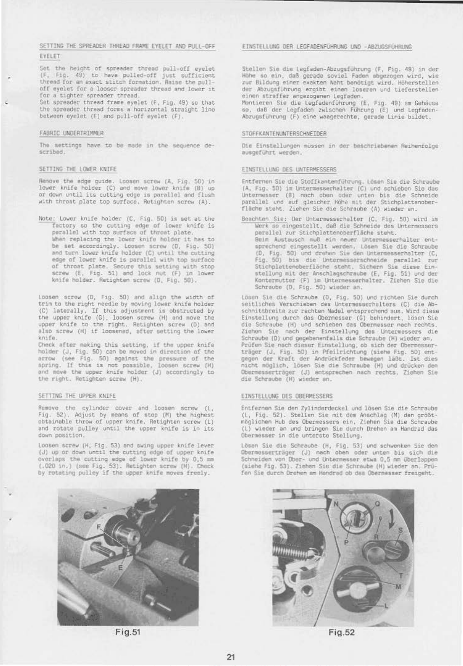
FABIUC
Tht
uo;O[RTR!I<MER
&tttl1"14jS
have t.o
scnbltd.
Rtmovt tl'le
lowtr
or
daMn
w1th
throat
!Iota:
l1ctory
p1rellel
When
bt
end
edge
of
screw
!.;n~fe
Loosen #craw (0.
trlm
to
(C)
literally
the
upper
upper
l'llsO
&crew
l(ntfe.
Oh~ek
holder
urow
spr1ng,
end
110ve
the
rlght.
knife
U'1til
lower
replacing
set
turn
of
throat
holder.
tha
knife
after
(J,
(s.ee
If
the
eC:ge
holder
its cut1ar.g
plate
l:,,~fe
so
the
'<~ith
accordingly.
lcr.er
lowe:r
plate.
(E.
fig.
right
.
If
knife
to
(H)
if
•aking
Fig.
Fig.
t1Us
upper
Retighten
be
suide.
top
loosen
{C)
surface.
and
holde•' {C,
cuttJ.ng
top
svrhcc
~he
lower kn1fo
tnife
ICnife
holder
is
Secure
51)
Retisnten
Fig.
50)
needle
th1s
by
adJuStmont
(C), loosen
tha
right.
loosened.
this
setting.
SO)
can
be
SO)
against
is
not
knife
screv
~de
1n
&crew
movo
lower
edge
1~
purttllel
Rul.lijhton
rig.
50) i!'l
edge
of
of
UU'08t
loosen
screw
(C)
until
parallel
thu
$ett.1ng
and
lOC<
nut.
scr~
and
{D.
al1gn
movtng lower k
screw
Rot.u)hton
oft.er
t.Ot.ting
1t
!!lOVed
1n
tho
posstble.
holder
(J)
(H).
t.M
~eq..Jence
(1\,
;::}~.
\ntfe
and
sc~
set
lower
plate.
hOlder
lt
(0,
the
wU.h
t.oP $ur-face
w1
(F)
F1g.
50).
the
widt.h
nife
iS
obstructed
(H)
and
screw
the
thO
upper
fHreetJon
preuure
loosen
screw
accordtngly
50)
(B) up
rtosh
(A).
at
knife
has
Flg.
o..ttiog
th
tn
lowe-r
holder
111ove
(0)
low
knife
of
o!
de
-
in
tne
is
~o
50)
stop
of
by
th-e
and
er
~he
the
(H)
to
S T
OJ.
f-
UHl
f
I•Ut~TERSCHNE
Oit
Einat.ellungen
a~fUhrt
Elt;SlllW.G
Entftrncn
(A,
F1g.
Untermustr
panllll
fliche
81Ji1Cht.e•1
Work
porollcl
8o;111
IPNehc~d
(D.
Flg.
St1Chplottenoberfl&Che
stellung
Kontt~tter
Schnubo
ldsun
:;olt.ltchos
:;chnittbreit.e
Ein:.toUung
dio
Schroube
Z1ohon Slo
Schroubt
Pru!en
trigor
gegen
n1cht
WCrde."\.
OtS
I.HTEAI!ESSERS
S1c
d~c
SO)
1m
Unte~csserhalter
(B)
vl">d
auf
#tOht
lichen
Sic
:
Oer
~o-elngestellt,
tor
AvsUvseh
c1ngestellt
hg.
50)
50)
bu
1111t
(0.
Sto
die
Schraube
Ver-schieben
:ur
(lurch
(H) vnd
nech
(0)
und
gegebenenfalls
Sit
n.octl dl.eser
(J.
F1g. 50)
dvr
~oft
.-oghCh,
losen
Cberwessort.r.ger
~it
Schroubt
{H) wJ.eder
IOER
~en
1n
der
bf'Sehrlebl!nen
Stoffkantenfvhrunq.
(C)
noel\
$tichplattenoberflicht
und
<Jer
(F)
Fig.
rechten
der
(J)
e-ben
gleichcr
Sie
Hohe
d1e
oder
Schraubo
Untermesserh
daB
die
CMJB
eln
never
werden.
drehen
d1e
Msehlegsenraubt'
1m
50)
des
das
()bermesser
S1e
lhte~Wtsseraef'loelde
$teht.
Unte~sserhelttr.
wteder
(0,
Fig.
Untermossorhttltou
Nadel
schieben
der
Einst.ellung
Elnstellung,
1n
Pfeilriehtung
AnOrVctfeoer
Sie
die
Schreube
ent.Spreehet\ ntcr.
en.
unttn
•i
L
altor
Schntido
losen
c~
SlChti'fl
an.
!SO)
entspruchcnd
(G)
das
Obomtcsor
die
Sehraube
ob a.ich
b~to
Reihenfolge
lOitn
Cler
Sie
die
und &chieben
bis
die
Stichplattenober-
(A)
'Nieder
(C.
Fig.
50)
des
Untcrmcssers
Schraube
Sie
Scnnaidc
an.
wird
&teht.
Unteroe&serhalter
Sie
die
Schraube
unurwsserha:ter
paralle:
Sie
diese
(E.
flg.
51)
und
Ziehen SJ.e dJ.e
uf'\CI
rtchtC!l
Sie
(C)
die
t~us.
lfird
bohtnc:lort, l()sen
nach
rechts.
dOl
Untcrmossers
(H)
W"icdcr
der
~erresscr~
(llthe
(H) und drVc;l(en
rechts.
Fig.
50)
laB~.
:.st.
Ziehen
das
i.Jt
cnt-
(C.
zur
Ein·
der
dvrch
Ab-
di.ese
Sie
dle
an,
entd1cs
den
S.1e
SETTING
Remove
F.ig.
obtoinoblc
ond
do•n
Loosen acrew (H.
{J)
overlaps
{.020
by
THE
the
$2}.
rotote
pou
t101'.
up
or
down
t.he
1n.;
rotGting
UPPER
cyhncrer
Adjust
t.h.l'ON
pulley
cutting
($ee
pulley
KKIFE
by means
o(
upper
ont
Fig. 53)
until
Fig.
if
cover
il
the
e1ge
53).
the
end
of
stop
knife.
the
upper
and sw1ng
cutt.ing
of
lOiter
Retighten
upper
knlft
loosun
(~)
tho
Retighten
knife
upper
odgo
o1
upper
~I'IJ.fe
SC:I't'"'
.oves
sct·e·"'
highest
screw
J.S
knife
by
(H).
freely.
in
lever
l::nife
0.5
o.eek
(l.
(l)
its
ca
E_INS_IHLUNG
Fntferntn
(l,
rig.
mOglichtn
(l)
wltdtr
Obermeaaer
LOson
S10
OES
Sie
52).
Hub
an
in
die
den
das
und
die
Obermoasortr.,ger
Schntldtn
(s!thl
f~
Slt
von
Clber- und IJntertnP.Sstr
F1g.
53).
durer. Drehen
OBEAMESSEAS
Zylinderdcckcl
Stellon
S1e m1t
Oberrncsscrs
bringon
unte
rste
SChreu::>e
(J)
ZJ.ehen
(H,
nach oben
S1e
-.
H:andracl
und
dCil'l
cin.
Sic
durch
Stelluog.
Hg.
53) und
od1r
d1e
Schr-aubt
Ob
oea Olotr,•user
loaen
Anachlag
Ziohen
Sie
l)l'ehen
schk'Cnl:.cn
unt.on
ttwl
D.
{H)
Sie
die
(H)
die
am
bu
5
tam
wteder
Schra~be
den
gr06t·
Schraube
Handrad
SJ.e
SlCh
das
den
dle
Uberlappen
an.
Pro-
!Teigeht.
Fig. 51
21
F
i\1
.52
Page 12
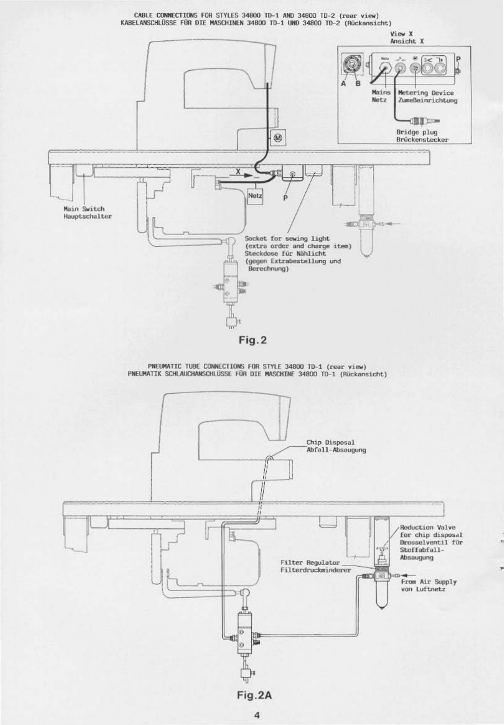
CABLE
KABELANSCH
C(HECTl~
L0SSE
FOR OlE
FOR
..
Sl"YLES 341100
MASCII
l NEN 34000
11)-\
TO-l
AND
34800 T0- 2
UNO
34800
(rea
r vi
TD-2 (Ruckan
"")
sic
ht.)
Vi
An
ew
X
sicht
X
....... -..........
··
····
-·u
l
r
""\..,
.....
l
Ma
in
Switch
~upt.scholt.c
~
IJc
A B
Ma
Ne
!
I
l
_
.,,
..
,_.,,
..
r
J
...
_
...
. - •
...,.:::=x,
~:;:'T:::f:;-::
;rrlr.;.J
,
,
h
'-
\
.l
,_
.
¥w,..
.
u-·
......
_,
.......
&
~
Socket
(crtra
Stcckdose
(gegct'l
Ocrcchnung)
...
~
···-·"""'
~
·········-···
"'
I
p
for
sewing
order
£xtrabes
and
fiir
Niihlicht
II
__
!
'-?--
light
charge
t.eJ~ung
~u·
i-)
und
,_,,.,_
IF.,.
l i
j
b
@·~~
:t@
I
ins
tz
Me
tering
Zurle6einricht.ung
I!Tidgc plug
OrOckcnsLecker
............
.
.,
Device
·-
~
PN
EU14ATI
PNEUMA
TIC
K
SCHUUJCHAHSCI
,..
~
..
~
"'
~}!
Fig. 2
TliSE CONNECTIONS
ILOSSE
FOR
FOO
DIE
STYLE
MIISCHIIII'
34800 TD-1
/
34800
Ch
i o
(r<!
ar
vi ew)
T0-1 (Rock
••
ansicht)
I
I
.
.u
..
l I
~~~
Ill
v
Filter
Filterdruct.aindct'Ct'
h f'l'OII A
'-
I
Regulat<>r
1/
ii
••
for
chip dis
OrossoJ.
St<>f
Absuug.ng
von
vent
fob
fall-
ir
Luftnetz
1/"d
SU
l ve
posdl
1
i
pp
ly
fUr
.,.
. '
li"
!::(](~
&
Fig. 2A
4
Page 13
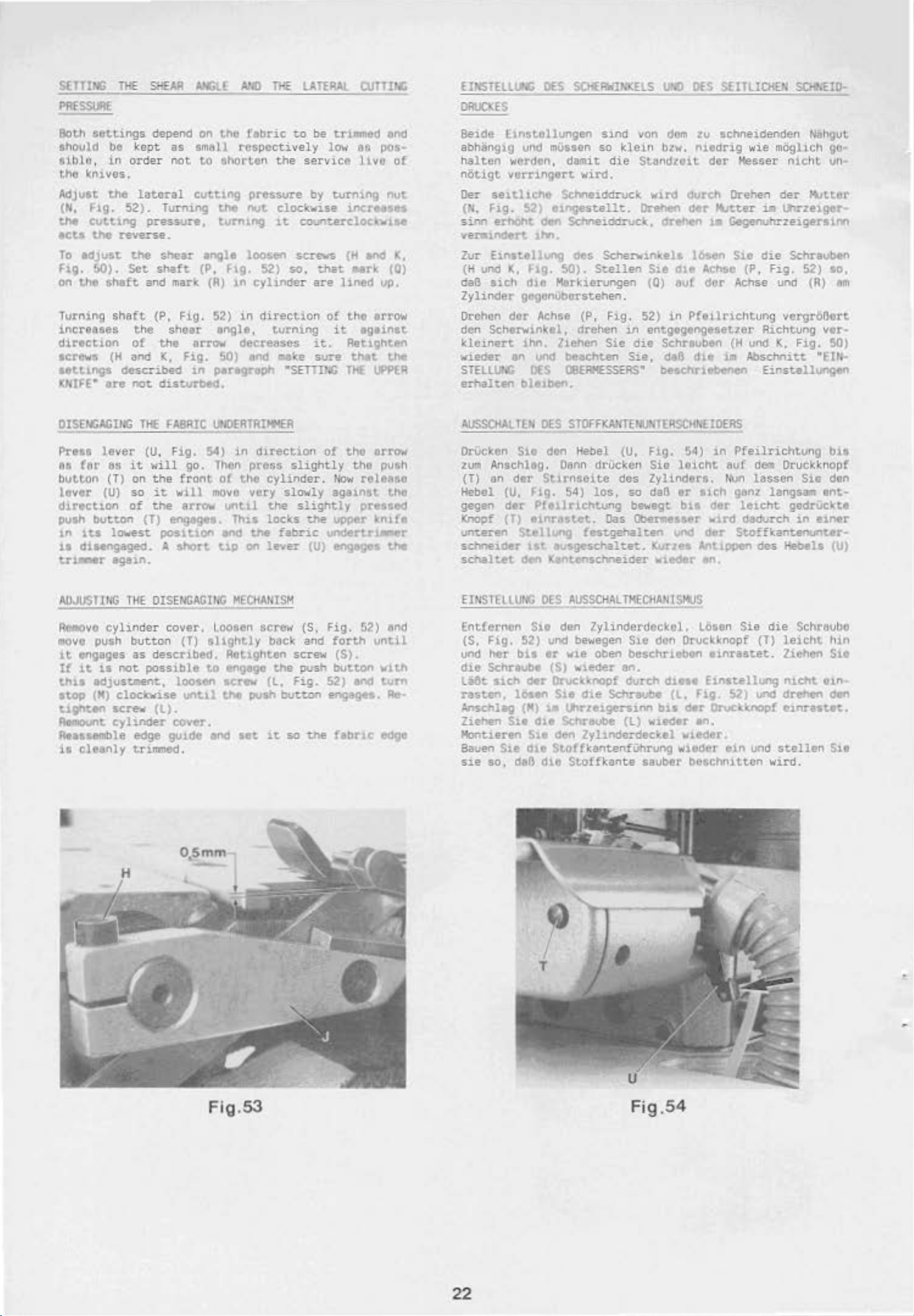
SETTlNG
PR£SSlllE
Both
settings
ahoold
be
aiblc, in
thO
knives.
Adjust
(H,
the
ecu
To
Fig.
on
Turning
Flg.
cuttlt'Jg
the
edjust
SO).
the
snaft
the
sha(t
increases
direction
screws
(H
aett1ngs
ICNtFE•
are
THE
SHEAR
depend on
kept
as
order not
lateral
52) . Turn.il'lg
pressure,
reverse.
the
shear
Set
shaft
and
mark
(P, Fig.
the
shear
of
the arrow decreases
and K,
described
not
Fig.
disturbed.
AhGLE
smflll
to
cutting
anglt
All)
tho
fabric
rospect.ively
shorten
pressure
the
nut
tum1ng
l00$en
(P, F1g. 52)
(A)
1n
cylinder are
52}
in
engle,
50) and
in
peregnpl'l
THE
LATERAl
to
be trimmed
the
service
by
clockwise
1t
counterdOCk.\flH
screws
so.
direction
turning
it.
-na'<e
•semr.c
low
turning
that
of
it
sure
llJTTING
eG
pos·
lho
nut
increases
(H
and
mark
lined
up.
tho arrow
against
Retighten
that
THI
IJPP(R
ond
of
1(,
(0)
thl:
ElNSTHLUNG
DRUCKES
Seide
Unst.ollungen
abh.Sngig vnd
h
elton
nOtigt
Oer
(N,
s.itvl
nrainder1.
Zor
(H
daB
Zylinder
Drohan
wordon,
vorringert
seitllche
Fig.
52)
ert.oht
£inatellung
und
K,
Ftg.
sich
dto
gcgcnUborstehen.
dor
1M.
den Scherwink
klcinert
wieder
STELLUP.C
erhal~eo
ihn,
an
und be.achten
DES
ble1ben.
DES
SCI<EAIIli<J(fLS
sind
mUssen
damit
so
di.c
klein
UNO
von
dom
btw. niedrig
Sttmdtoit
DES
SEITLIOtEN
zu
schneidenden
der
Hesser
w
ie
mtiglich go-
SOfiEID-
Nbhgut
nic
hL un·
wird.
ScMeiddruck
etnges~ell~.
dlltf' Schneiddruc.lc, d:rehen w GegenuhrzeigersuV'I
des
Schervinkels
50).
Stellen
Markierungen
Achee
el,
liehen
(P,
Fig
drehen
Sie
OBERXESSERS•
vird
Orehen
durch
der
loseo
Sie
dte
(0)
eu!
. 52)
in
Sie,
in
Pteilrichtung
entgegengesetter
die
Schrtuben
daB
dte
besehrlebenen
Drehen
HUtter
Sto
Achse (P,
<for
Achse und
{~
und
tm
Absctvlitt
der
~tter
i8
Uhrzetger~
die
Schraubeo
Fig.
52)
so,
{R)
em
vergr06crt
Rtchtung
~.
Einst.ellungen
Fig.
vor·
50)
"EW~
DISENGAGit<G
Prett
ea
lever cu. Fig.
tar
bul..t.on
lever
direct1on
Til€
as
it
wi
(T) on the
(U)
so
it
of
the
push but.con (T)
1.0
its
lowest.
i.e dia.engaged. A
t.r~r
agai.n.
Ao.JI/SllNG
Reaove
110ve
1t
If
thl.S
stop
tigt'lt.en
~t
cyl1n
push
engages as
it
is
not.
adjus~ent.,
(
H)
clockwise
screw
cylinder
Atusemble
11
cleanly
posttlon
THE
OISENGAGrt.'G
der c
button
described
possible
(l).
edge
trimmed.
F~RIC
S4)
ll
go.
front
will
move
arrow
ensages.
$hart
over
.
(T)
slightly
to
loosen
unul
cover.
gu1Ckl
•nd
Ufll£RTRI,..ER
in
direction
lhon
oC
unt1l
Thl.s
end
u.p
press
the
very
Ule
on
slightly
cylinde
slowly
che
locks
fabric
lever
MECHAU!SM
Loosen
screw
back
. Rot1ghten sc
.,gage
screw
the
push
tet.
the
(l,
button
ic
Fig.
so
ot
r .
tfow
against
slightly
the
upper
undertr1....er
(U)
~.s
{S,
Fig
and
forth
rew
(S).
posh
button
52)
engagea.
the
febru:
th-e orrow
the
push
release
the
preued
kntfe
the
. 52) end
until
Ylth
and
~~
Fte-
edge
AUSSCHALTEN
OrVck<m
z:ur~
Anschleg.
{T)
an
Hebel
gegen
Knopf
unteren
:scMeider
sehaltet
EINSTELLUNG
Entferr\On
(5,
Fig.
und
Mr
d~c
Sehroube (S)
U8t
s1.ch cler
rasten.
l.rlschlag
Ziehen
Hontieren
Bauen
sie
Sie
so,
DES
Sio
dtr
Stirnseito
(U,
Fig.
der
Pf•tlnchtung
(T)
e1nrastet.
Stellung
tat
drft
DES
Sie
52) vnd bewegen
bl.l
er
l61en
(M)
Sie
d1t
Sie
die
daB
die
STDFFKANTENUNTERSCHhEI~
den
Hebel
Oann
54)
ausgeschalut.
~tenschneide:r
{U,
Fig
. 54)
dri.i<:ken
los. so
dos
Sie
Zylindera.
daB
bewegt
Oa.s
llloe:nnesser
fMtgehal~en
uod
Kurzes Anttppen
Yleder
loicht
er
t1Ch genz
bu
der
wtrd
der
en.
in
Pfeilrichtung
euf
truo
le.tcht
dadurch
Stoffkanumunter~
AUSSCKALT•ECHANISMUS
den
lylindcrdecltol.
Sie
vie
oben be.$Chntben
wieder
Oruck\nopf
Sie
die
~
"'rteJ.ger:sl.Nl
SChraube
den
ZylJ.nderdeckel
an.
durch
5eh.raube
(l)
w1eder 1n.
StoffkantenfUhrung
Stoffkan
te
sauber
don Oruckknopf (T)
bu
LOsen
d1t1e
(l,
Fig.
Otr
wteder.
wteder
boschnitton
Sie
einrasr:et
£inst.ellung
52)
Olvett.nopf
ein
dent oru
lassen
Ste
langsan
gedri.ic\te
in
des
Hebela (U)
die
Schroube
leicht
. Ziehen St.e
nteht
und
c:treh4:ln
Cl.nra5tet,
und
stellen
wird
.
bis
ckknopt
don
ent·
einer
hin
tl.O·
dtn
Sit
o.sm
m
Fig.
53
Fig
.54
22
Page 14
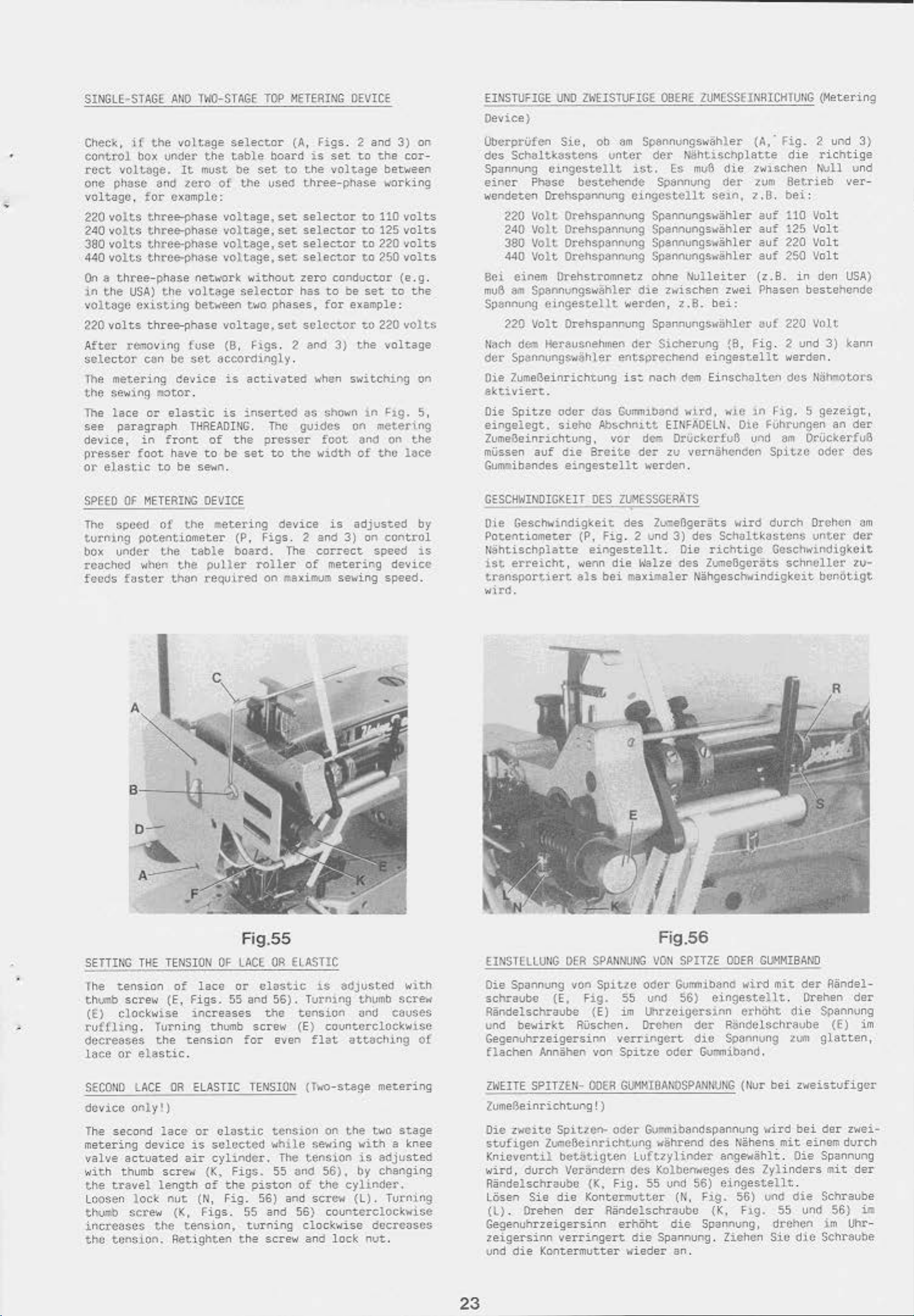
SINGLE-STAGt
AUO
TWD-STAGE
TOP
METERING
DEVICE
EINSTUilGE
Oevice}
UNO
Zk'EISTUFIGE
OBERE
2UM($$ElNIHCHlUUG
(Met.ering
Check,
eontrol
rect
one phtJse
voltage. for
if
the
box vn.der
vOlU)ge.
aM
volt~ge
the
It
must
teto
cx~mplc:
220 volts three-phase
240 vol
380
440
On a three-phase
10
voltage
220volts
volts
volts
the
ts
thre(H:)hase
t.hl'ee-phase
three-phase
USA)
the
existing
three-phase
net~.'Ork
voltage
be~een
After t·emovil'9 fuse
selector
lhe
the
The
see
device,
presser
or
elastic
can be
metering
sewing
lace
m
or
paragraph
in
foot
to
set
C'evice is.
~tor
.
elastic
THREADI!iG. The
front
have
of
to
be se-,;n.
selector
~ble
of
voltage,
•Joltege.
voltage,
voltage.
te
the
board
set
use<:S
set
set
set
set
without
selector
two
phases, for example:
voltage,set
(B.
Hgs
. 2 end
accordingly
act.ivated
is
inserted
the
presser
be
set
to
(A,
Figs
is
set
to
the
voltage
three-phase
selector
selector
selector
se 1 ector
zero
has
to
selector
.
'-'hen
I.IS
shO~<·Il
guides
foot
the
width
. 2
and
3)
on
to
the
cor-
between
~o.'Orking
to
110 volt.s
to
125
volts
to
220 volt.s
to
250 volt.s
conduct.or (e .g.
be
set
to
the
to
3)
the
switching
1.0
220 vo
lts
voltage
on
~:1g.
5,
on metel'\ng
and
on
the
of
thU
lace
ObcrprVfen
des
Schbltkastcns
Spunnung
eincr
"''endeten
220
240
380
440
Bei einem Orehstromnetz ohne
mu6
am
Spannung
220
tit~Ch
d
dcr
Spannungs·,;-l)h
Oie ZumeBeinrichtun-g
~ktiviert.
Die
Spitze
eingelegt.
Sie,
ob
u1ltcr det' Nlihtischp
cingcstellt
Phase
bcstehcnde
OrchSpcl!Mung
Volt
Orehspannvng Spannungsw8hler
Volt
Orehspannvng
Volt
Otehspannvng
Volt
Orehspannvng Spannungs-wi;hler
Spannungsw§hler
eingestellt
Volt
Orehspannvng Spannungswtihlcr auf 220
(111
Heravsneh;llen (!er
ler
oder
dos
siahO Ab$chnitt
am
Spannungs~<·ahler
1St.. Es
mv-6
Spannung
die
det
O.lngcstellt. se1n,
Spannungs~ahler
Spannungs~8hler
Nulleiter
die
z~ischen
werden,
z.8.
Sicherung
entsprechend
is~
nach
clem
Gu~m~ib<:ll'ld
~ird.
zwei Phasen
bei:
{8,
eingastellt.
Einschaltcn
,.,ie
EWFADEUI.
ZumeOeinrichtung, vor de.-. DrUckcdu6
mU.ssen
Gumibandes
auf
die
8reita
eingestellt
der
zu verni.ihendon Spit.l:C
"'erden.
(A.·
Fig
. 2
latte
die
zwischen
zum
8etrieb
?.6.
bei:
auf
110
auf
125
auf
220 Volt
auf
250
(z .
B.
in
richtige
,.,\.111
Volt
Volt
Volt
den
beste
Volt
Fig
. 2 und
werden.
des
tiijh-o\.Ot"$
in
Hg. 5 gezeigt,
Oie Fuhrungen
und
am
Ot'(id:erfu8
oder
und
hendc
3)
an
3)
und
ver-
USA)
kann
der
des
SPEED
The
Of
speed
turning
box
under
reached
feeds
fustcr
METERING
of
OEVICE
the
~
potentiometer
the
table
when
the
than
pu
teQvired
etering
(P,
board.
Uer
device
Figs
roller
on
The
maxia:um
is
. 2 and
correct
of
metering
adjusted
3)
on
se\o•ing
control
speed
device
speed.
by
is
CSSCHWlNOlGKEIT
OES
Oie Geschwindigkeit
Potentiometer
!Hihtischplatte
i
st
erreicht,
transportiert
wird
.
(P,
fig
eingestellt
wenn
~ls
bei
ZUMESSGERATS
des
Zua:.eBgerats
. 2 und
3)
de-s
. Die
die
walze
max~ler
des
N~hgesc~ndigkeit
llird
durch
Schaltk.:~stcns
richtige
Gcsch~<•irn:hgk.eit
Zume6gerats
Orchcn
unter
schneller
::tm
der
zu-
bonotigt
SETTING
lhe
th~b
(E)
tuffhng
decreases
lace
THE
tension
scre"'' (E,
clockwise
. Turning
the
or
elastic
SECOJIO LACE
device only!)
The
second
metering
valve
•,;ith
the
actua<oed
thumb
tr~vel
lace
device
length
Loosen lock
t....,_~
increases
the
SC't'ew
the
tension.
TENSION
of
lace
Figs.
increases
thvmb
tension
.
CR
ELASTIC
or
ts
selected
air
cylindot·.
screw
nut
(K,
of
(N,
(K,
Figs.
tension,
Retighten
Fig.55
OF
LACE
or
55 and
screw (E)
for
TENSION
elastic
Figs.
the
piston
Fig.
55 and 56)
toming
the
OA
E~ASTIC
elastic
56).
the
tension
even
te;lsion
•..,hi.le
The
55 and
of
56) and
clockwise
screw and
l.S
adjusted
Turning
thumb
;.lnd
countarclockwlse
flat
(
Jwo
se·,;ing
tension
sct·c.""'
uttaCili•'9
-st~ge
on
the
with
is
56),
by changing
the
cylinder.
(l).
metering
two
edjusted
Turnjng
counterclockwise
decrC;.lSCS
lock
nut
with
screw
causes
of
stage
a knee
.
EINSTELLUIIG
Die Spannung von
schrauhe
RSnclelschnub-e (
und bewirkt.
Gegenuhrzeigersinn
flachen
ZWEITE
DEA
SPAIINUM;
(E,
Ftg
RUschen
Annahen von
SPITZHI-
ODER
Spitlc
odor
. 55 und 56)
E)
im
Uhnc~gersil'ln
. Drchen
verringcrt
Spitze
Gt!MMI0AN0$PANIIVNG
Zume6einrichtung!)
Die
z•.n:titC
stvfigen
Kniovontil
wird.
Randelschruubo (K,
LOsen
(1.} . Orehen
b.:me6e
durch
Sie
Spitzen
lnti
bet
titi
gten Luftzylinder
Vorundct·n
die
Kontermuttor
dar
- ode:r Gu:rtnibandsp.eonung wire!
chtvng vi;hrend
des
Fig.
55
Riindelschraube
Gegenuhrzeigersinn erhOht
zeigersinn
umi
die
verringert
Kontermutt.
die
er
vieder an.
Fi
g.56
VOfl
SPITZE
Gvrnmibano
OOER
wird
eingestellt
erhOht
dcr
Ralldelschravbe (E)
dte
SpaMung :(U'!l
odor
Gvmmib::tnd.
{tlur
des
Ulihens.
ang~
....
K.o
lbemte
unCI
die
ges
56)
eingeste
(~.
Fl.g. 56) uod
(K,
Spannung,
des
Ftg.
Spannung. Ziehcn
Cl.LI1Ml8ANO
mit
der
. Orehen
die
Spannvng
glatten,
bei
z·.teistufiger
bei
der
mit
einam
ahl<o
. Oie Spannung
lylinders
llt
.
die
Schrauhe
55 und
drchcn
Sic
die
im
Schravbe
Riindel-
der
zwei-
dvrch
mit
der
56)
Uhr-
im
ill
23
Page 15
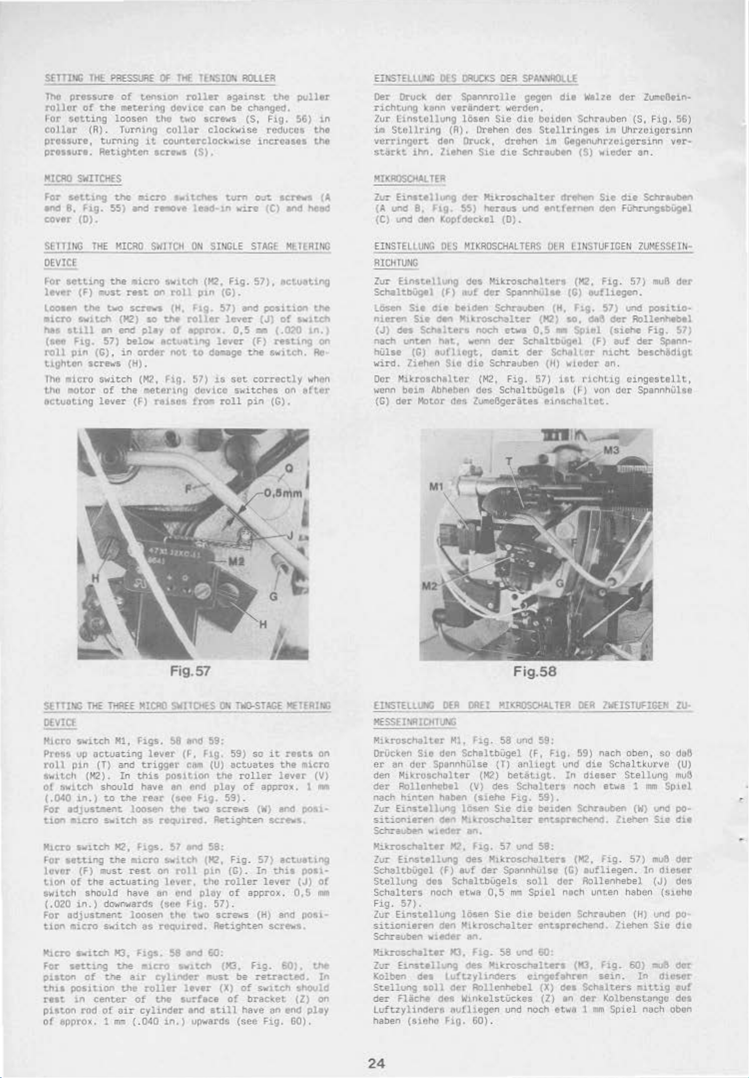
S£TTlh$
ThO
pressure
rollor
~or
collar
of
~otting
pressure,
pressure.
THl
P~ESSURE
of
the
me
loosen
(A)
.
Turning
turning
P.etightcn
OF
THf
tens1on
ter1ng
dov1ce
the
two
collar
1t
counterclockwise
screws
l(t,'SIOt.
rolle-r
can
scre-NS
clockwise
(S).
ROLLE;l
against
be
changed.
($
,
increases
the
puller
Fig.
S6)
in
toduc<n~
the
the
Eih'STELtl.l'.G
Oer Druck
richtung
lur
im
Stollrlng
vcrtingcrt
sttt.t·l:.t
konn
Linstcllung
i.hn.
DI:S
ORt.CKS
dor
Spamrolle
ver8ndert
lOsen
{A).
den
Orvck,
hthe-n
OER
SPAJ,·~ROLLE
gcgcn
werdun.
$)e
dlC
Orehen des:
dt·chcn
S1e
die
Sc.hra\Jben
die
Welle
bcidon
Stollringes
im
Scl'lrauben
Gege-nuhr2:el.gCr
(S)
der
($,
ia
Uh:ttcigc1'.s1nn
wteder
an
zu-
cDein~
F1g.
sinn
ver·
.
56)
HICAO
For
end
cover
SE
S'.tiTCHfS
tet.t1ng
8,
lllt<G
F1g.
(D).
55)
THE
DEVICE
For
sctt1ng
lever
Loosen
(F)
the
the
must
tvo
atel'O swttd'l
hils
U1ll
(&H
roll
\.Lghton scre-..·s
Tho
•icro
tho
.otor
Actuoting
Flg.
pin
an
57)
(G),
switch
of the
lever
the
aicro
and
KICRO
eicro
rest
screws
(H2)
enc::
bela•
in
order
(H),
(M2,
(F)
s.tlt.c:Ns
remove
S<IITCII
on
so
play
act~.Httlng
metering
raises
swttch
roll
(H,
the
roller
of
epCJrox.
not.
Fig.
lead-1n
ON
p1n
flg.
to
~7)
dovice
f~
UJrn
vire
SINGLE
(H2,
Fig.
(C).
57)
lever
0,5
lever
domage
is
sot correctly
s.ritches
roll
out
STAGF
57),
and
(J)
Q'll
(F)
the
pin
sc~
(C)
and
MlllRII<G
ectvoting
position
of
swi.tch
(.0?0
rest1ng
switch.
on
(G).
(A
hee~
the
tn,)
on
Ae-
whtn
ttfter
HlXIIOSCHAl
Zt..-:-
Einstellung
(A
und
(C) und
B.
den
TEA
F1g.
EIIISTELLUNG
RlCHTU'G
Zur
Einstetlvng
SchaltbUgel
losen
ntcreo
(J)
nach
hUlse
wird
Ocr
~o.·or.n
(C)
Su
cllt
Stt
deft
des
Schelters
unten
(G)
~tufhegt,
.
7iehf'n
Xik.roschelter
bEum
Abheben
der
Motor
dc-r
ltik:roschalter
55)
hc:aus
Kopfdeckel
OES
HIKROSCHALTERS
des
(F)
auf
bei~
Hllr:r"OSChalter (H2)
hltt,
S1c
dft,
~ooem
dlo
(D)
ttikroschalters
der
SpannhUlu
Schrauben
noch
et:Wa
der
ca:uit
Schrauben
(M2,
Fig.
des
SchaltbUgeh
Zurwllgeriites eintlch&U.ot.
drehen
und
entfernen
.
OEA
(G)
(H.
10,
0,5
""
Sc.haltbugt\1
der
Sc:Mllur
(H)
wiodcr an.
57)
ilt
'llll
Sie
die
~en
FUhrungsbUgel
LlliSTUFIGEII
(H2,
Fig.
oufllegen.
ftg,
57)
Ul"'d
088
dcr
sc)lel
(j.:) von
(siel'te
(F)
auf
n1cht
riC-IH,lg
eingestellt,
dor
lrf\ -
Sc:hrauben
ZUI<CSSElii-
57)
muB
der
pcn.itl.O·
Rollenhebel
Fig.
57)
der
Spann·
oes.ch8digt
SpannhUhe
SUTING
THE
DEV!Cf
Hicro
Pros&
roll
$·.,J.tch
o!
(.040
For
t1on
Klcro
~r
luvor
t.1on
switch
switch
up
p1n
(H2) .
t.wttch
il'l. )
edJuSUI'Ient
•icro
switch
sct.ting
(F)
of
the
should
(.020 in. )
For
adjustment
tion
micro
~l.CTO
For
p11ton
tl'lil
roat
piston
of
s..i~ch
s.euing
of
position
in
rod
&pprox. 1
Fig. 57
llHE
actua~ing
(T)
should have
~o
swit-ch
must
dn•..tn-Hard!'l
s~itch
Ute
center
of
Ml,
and
In
MICRO
figs.
this
SJIITCHES
$8 and 59:
lever(~.
trigger
posit
an
t.he
rear
(see
loosen
K2.
figs.
t.he micro !-w:tch (H2,
rest
actuating 1 ever,
have
loosen
M3.
f1gs.
the
a1r
the
of
oir
~~G
(.
the
as
requued.
~7
on
roll
en
end
(soe
the
as
requir~d.
$8
~u;ro
rollor
cylindor
040
sw1teh (H3,
cyJ
1.nder IIUSt be
the
surface
1.n.)
o,
f1g. 59)
Cftm
(U)
ton thO
eoo
ploy
Fig.
two
scre.rs
Redgh~en
•net
58:
p1n (G) .
the
pluy
F1g. 57) .
t"'·o
scre..-s
Ae~ighten
end
60:
lever
Md
(X)
ttill
vowards
lliO-STACE
so
actuates
roller
of
59) .
(W)
Fig
.
57)
In
roller
of
approx.
(H)
fig.
re-tracted.
of
swltch
of
bracket
have
(see
~TERUfi
it
rests
the
micro
lever
approx. 1
and
post·
scre-..s.
ectuattng
this
posl·
lever
(J)
0,!)
end
pol'!~·
screws.
SO).
r.hould
(Z)
an
end
play
flg.
GO).
on
(V)
1M
of
mrn
the
ln
on
EmSTEllv~
OEA
OAF
KESSEI'iAICHTUI.G
MlkiOschalter
Orucken S10 den
er
en
dur
den
MlkroGcholter
<let
P.ollcnhobel
,uch
hinten
Zur
Einstellung
si~ionieren
Schrauben
Milu'Qschalter
Zur
Eln&tellung
SchaltbUgol (F)
Stellung
Schalters
Fig.
57).
Zvr
Einstellung
si~ionieren
Schrauben
Hi.lr:.roschalter
Zur
El."stoJ
Kolben
St.ellung
der
d•s
Flacho df!'l W1nl:.clstUckes (Z)
Luftzylindern
haben
(sicho
M],
fig
Schal~bUgel
SpnnnhObe (T)
(M2)
(V) <les
habtn
~~n
~led~r
dOl
noch
($iehe
lOsen S1c
MlktOSchaltEr
an.
Ml,
Fig.
~e$
•uf
(!er SpannhulGO
SchahbUgel$
etwa
lOsen S1c dlC
dtn
H1kroschalter
wtecler
soll
M.
H3,
fig.
11.11'\g
'!!#!$
luftlylincers
der
Rollenhebel
ftuJltegcn
Flg.
GO)
.
~ll:roseh&Ueu
0,5
Kl.kroschalton
.
Fig.58
MlXROscHAllEA
58
uod
59:
{F,
Flg.
anliogt.
betatJ.gt.
Schalt.crt
hg.
die
57
und 58.
soli
m-,
Sp1ol
58 unci 60:
ctngtf•hren
und noch
und
In
59),
belden
eotsprtehet'IC.
(G)
dor
noch
boldtn
entsprechend.
(X)
del
en
etwa
OER
MISTU~='lGH·;
59)
nach oben,
die
Scha
ltkurve
dieser
noch
Sc:hreuben
Stellvng
e~wa
1
(W)
mm
Zteheo
(M2.
Fig. 57)
•ufliegen
Rollenhebel
unten
Schrauben
(K3,
Cig.
seir
Settahers
der
Kolbenstango
1
ftm
haben
llehcn
60)
.
SP1Cl
.
In
(H)
In
-1tt1g
nuch
ZU..
so
du8
(U)
mu:l
Splol
und
po.
s~e
d1e
mu6
d~r
d1eser
(J)
des
(Sloho
und
po-
Sl.O
dlO
~
ctcr
GlC~er
•uf
des
obon
24
Page 16
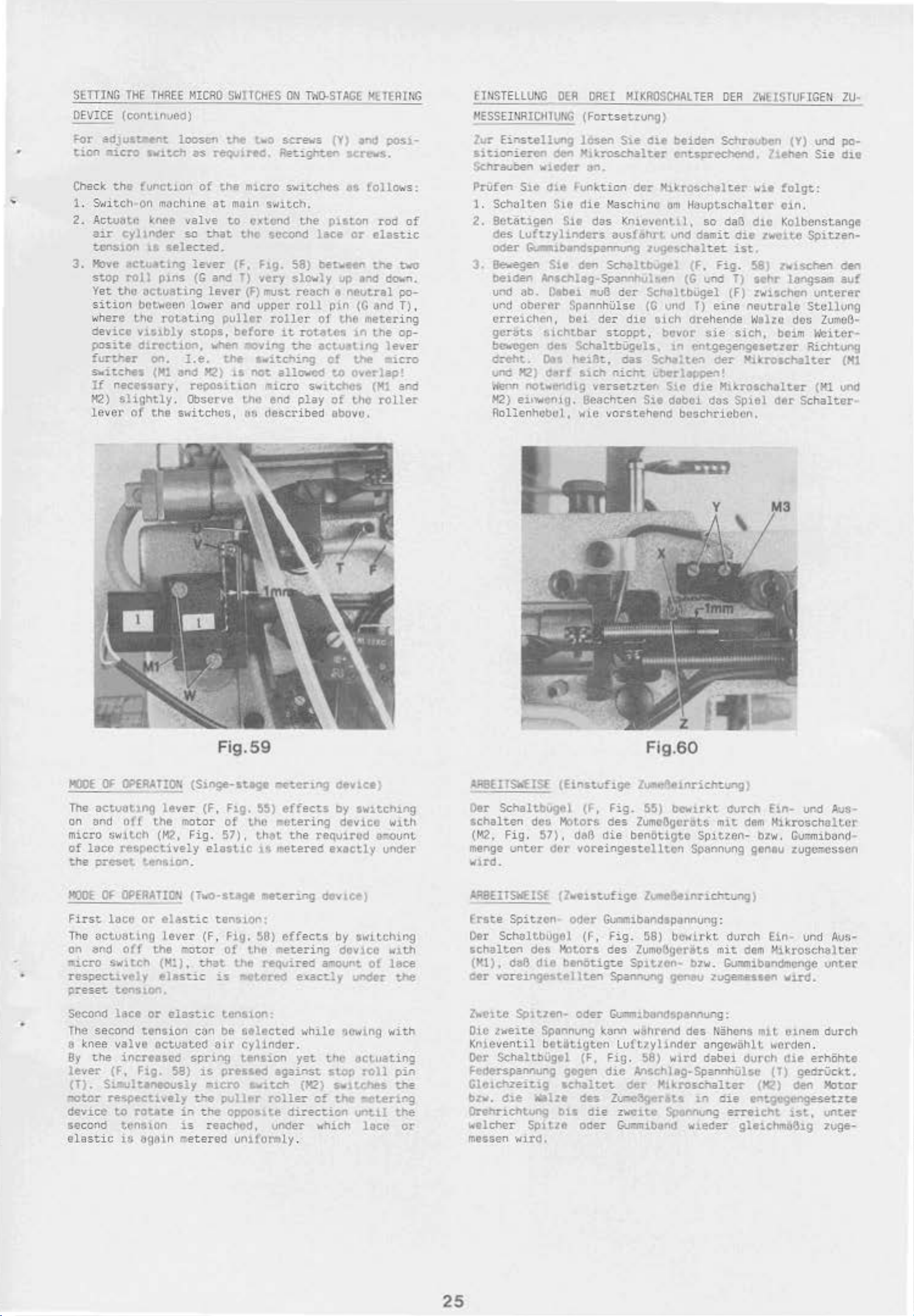
SETTING
DEVICE
For
•
tion
Che
1.
2.
J.
THE
(conunueQ)
&dJuStaent
aicro
ck
the
fuoet.10n
&.,
itch-on
Actutlt.O k
a1.r
cyl
tcnston
Hove
stop
Yet
s
w
device
posite
further
s-..itches
If
~)
lever-
ct'
rol
tho
actuating
ition
here
but.~een
t.ha
v1s1bly
dlr'Ochon,
r.ecessory.
slightly
or
THREE
sw.a.tch u .requ1rec.
l'lder
.a.a
MICRO
loosen
machine
nee
valve
so
selec:.ed.
1t1ng
p1ns
lever
(G
of
at
that.
and
the
SWITCHES
t.he
'.a
m1cro s·.,itches
main
to
ox:tt-1ld
t.he
(F.
Flg.
T)
vety
lever(F)must reach 3
lower
t'Ot.eting
stops,
on.
I.e.
(Hl
and
repos\tlon
. Observe LM
the
s-witchct;. l,ti.
when
>1'2)
Mel
puller
before
~v1ng
the'
lS
not
upper
awttching
micro
descri
ON
T'tiD-STAGE
scret.~s
Ret:gf'rten
sw1tCh,
t..he
scconc
58)
lace
bet111Hn
$lOWly
roll
roller
it
allowed
end
ot
rOt4te'
the
aCt.u4ltng
of
swttehe~
play
bed
('t}
act't"los .
as
pi
loton
or
up end
neutral
ptn
tho
1n
v-e
to
overlap!
of
tho
abovo'
HtTEAING
11nd
p()$.1-
rot
taw
rod
elastic
the
down.
(G
and T) ,
metering
the
lever
aicro
(Ml and
toller
s :
of
tvo
po-
op-
[JNSTELLUNG
~ESSEINRICinUt~G
lur
Einstellvng
<i~iercn
Schra~;.ben
Prufcn
1.
2.
Ste
Schalten
8et8tigen
des
Luftzylinders
ocer
3.
8ewegen
beiden
und
ab.
und
oberer
cn
·el.chen,
gorats
bcvcgen des
dreht.
VnG
'1:2)
,
,enn
H2)
eiiY.tentg. Seacht.en
Rolienhebol,
OER
ORE!
(Fort.setzung)
losen
oen
KJkTOSchalter
vltdor
clle
&.-lblndS-panr-ung
S1e
Anschlag-Spannhul~nn
O.be1
f>IChtbar
a.~
dlltf
no~f'!nchg
lJn,
Funktion
$10
die Kasc
S1e
das
ckln
~vB
SpannhUlse
bei
der
SchaltbUgels.
het8t,
stch
versetzter.
•o~ie
Schaltbugel
st.cppt, bovor
vorstehtnd
HTKROSCH•L
Sie
aie
TER
OEA
~iden
Schrooben
entsareohend.
der
>bkrosch<er
hinc
om
Hauptschalter
Knievenu
oushhrt
d~r
dio
oas
nicn't
Slt
1,
so
und
damit
lug~s.chalt.et.
(F,
Fig.
(G
und
SchaltbUgel
(C
und
T}
eine
sich
(frehende
sie
1n
entgegengesetzer
Scho.:.ten
c.:berlappe:'l!
Su:t
doboJ.
oer
dte
MlkrOSCI'I•lter
dos
bu::;chticbcn.
lWHSIUHGEN
liehen
wa
daB
dto
oie
two
ist.
58)
T)
sohr
(F)
zwlSChGn
neutrole
W.aho
sich,
b•tm
Mitroschalter
Sptel
aer
ZU-
(Y}
und
po-
Sie
die
folgt
:
01n.
Kolbenstange
te
Spiuen-
zvuetten
l6ngsam
den
auf
unterer
Stcllung
dcG
ZumeB·
Woiter·
Richtong
(Hl
(Hl
ond
Schalter-
MOOE
OF
CJ>EAAfiO•,
The
actu6ttng
on
und
off
micro
of
th~
MODE
First
The uctu&ting
on end
~cro
swttch
lace
respectively
prese~
or
OPEAAltON
lace
o((
SwltCh (M1).
or
res_:)eettveJy
p=-eset
second
The
& knee
By
!ever
(T}.
"JOtor
dev1ce
second
elastic
ten
1on
lace
s e
cond
tenuc.n
valve
the
increncd
(r,
Fig.
Si.ll.tluneously
re~tlvely
to
rotate
tcn!uon
1S bgAin
(Sloge-stegfir
lever
the motor
(Ml,
Fig
ension.
(Two-s~~
elastic
lever
the
":'~Dtor
t.hat
elast.ic
or
alasttc
eM
octu3tCC
spr1ng
58)
1S
tne
in
t.he
is
rwetered
Fig.59
(F,
Ftg.
of
.
57),
elastic
ten5ion:
(F
,
fig.
of
V'ts reQuireo
is
"Ct~recs
tens1on:
be
selected
air
cylinder.
tension
pressed
=tcro
puller
oppo!".:.te
reached,
untformly
r:et.e=-tng
S$)
effects
tho
~etering
th&t the
1!
~etered
111etering devlc-"!)
SO}
effacts
t.he
metering
Ct'#lce'
by
requtrud
exactly
by
a11ount
exactly
~·hilo
yet
the
against
s.-1tch
rolle
direction
under
(M2)
::-
.
stop
sw1t.cnes
of
thO
which
twttch~ng
device
wtth
u-~unt
under
swttchil'.g
dov1ec
uncki'
of
wlth
l&ce
the
sowing •,..ith
e~cL.uating
roll
pin
the
~~eteriog
unt.ll
locc
the
or
AEI8HfSktiSE:
Oer
Schaltbugcl
achalten
(Me,
Fi g . 57}, d86
menge
Wlrd
ARSEITSWfiSL
frste
Oer Sc
untcr
.
Spitzen
haltbugol
schaltcn
(~1).
Cer
l'-C1tC
Oic
daB
vorctngt:$
So1t2tn•
zweite
Knieventil
OCr
SchaltbUgel
(h.n$tuhge
des
Motors
dor
(Z-.eutuhge
oder
des
Motors
dte
btnOtigt.e
ell
Sponnung
betlitigtcn
(F,
voreingest.ellten
(f,
ten
oder
(F,
Federspannung gegcn
GlClehZeit.ig
bzw.
d.le
OTehnChWng
~o·elcher
messen
'Nird.
*h•
ou
Splt.tO
schaltct
des
die
oder
Fig.60
z~
"6etnrichwng)
Fig.
55)
bOwJ.tkt
des
lumollgorDl.$
di
e
benOtigtc
z....
Gl:mtnibandsp:mnung:
Fig. 58)
ces
ZumoGoertts
S?ttzon-
Spannung
Gumnub8ndspaMung:
~onn
w8hrend
Luft?ylinder
Ftg.
58)
dJ.C
Mschhg-Sp.annhUlst• (1')
der
~~\roschalur
Zur:lc3gttrtts
zwette Spennvng
Gu•,..m.tbilnd
Sptt~en
Spannung
etnrich:ung)
bow.l.rkt
bzw.
ge~ u l~Sitn
des
~ahens
ange~·Uhlt.
wird
da~ei
in
w.1.eder
durcn
mit
dvrch
mit
~Jmmibondmonge
Ein-
dem
Kikroschaltcr
-
bzw.
Gu~ibond·
qentu
dem
zugc~ssen
Ein· unci
Hikrosch<er
wird.
m1t
e1nem
urd
.a.us-
Au$-
unter
dur
ch
"'·orden.
durch
die
erreicl'lt
die
erhOhte
gedriickt.
(K-')
den
Motor
ent~'""Sesetzt.e
ut.
unter
gleichma(hg 2vge-
25
Page 17
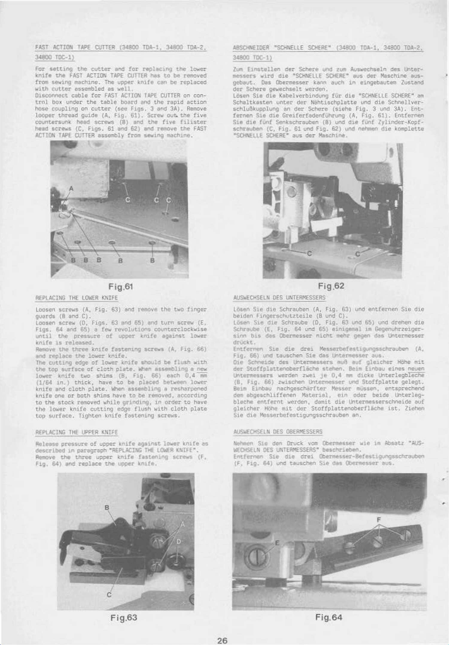
FAST
ACTIOII
~TOC-11
For
ltttlng
knitt
from
with
Olsconncct
trol
hO~O
looper
the
FAST
~~wing
evt.tcr
cuble
box
under
coupling
thread
eount.ersunk
ht•d
screws
ACTION
TAPE
T>J>E
the
~~ch~ne
as-sembled
CUTTER
cutter
ltCllON
.
for FAST
the
on
cutter
guide
he&d
(C,
CUITER
screws (B) and
Ftgs.
asseably
TAPE
The
as
table
(A,
61
and
(see
Fig.
(~
upper
~o·ell.
ACllON
bo&rd
and
Tl)A-1, 34eoll
for
replec1ng
CUTTER
hltl
~n1fe
TAPE
ond
hgs.
61).
62)
ft'OII aew1ng
3 ond
Sere·.,.
the
and
ro,;-2.
the
lower
to
be
removed
cen
be
replaced
CUTTER
on
con
-
tho r6pid act ion
3A).
Remove
out:..
the
five
five
filister
re-ove
the
machtne.
FAST
ABS0<'<£1D€R
3A800
Zvm
-es~crs
IOC-1
Etnst.ollen
l
w1rd
"SO<,EllE
oer
Schere
die
•SCH.'lEllE
gebout.. Oas Obermesser
dor
SChere
l6stn
Schaltkelten
schlu6kupplung en
ftrntn
Sie
dte
schrauben (C. Fig.
•s()I·,·.LLE
geo..~ech:selt
Sie
die
Kebelvel'blndung fUr
unter
der
'er
Sit
die
Grelferf&dtnfUhrvng
(Unf Senkschrauben
61
und
SCiiERE•
aus
vetden.
SCI<ERE"
J:ann
Naht~schplotte
(3A800
und
z:u:~
SCHEAt."
t~uch
TOA-1,
Ausweehseln
ous
der
tn
ei.ngebaut.em
die
"SCHNFLLf.
und
~
des
Joliaschine
SCHERE
die
Schnellver-
Tl)A-2,
unter-
aus-
lusumd
"
Scherc (sililhit Fig. 3 und 3A). Ent-
(A,
Fig.
61).
Entferoen
(B)
und
d~t
fUnf
lylinder·Kopf·
Fig. 62) und
der
Maschi,...
n•hmen
dte
komplette
am
REPlACING
Loosen
gu:~rds
Loosen
Fi.ga.
until
lunft
~v~
and
replace
~
cutttng
the
toP
lowet>
(1/64
~nife
~nift
to
tho st.ock removed
tho
lo~~~·or
top
surf6ce.
REPlACING
Rtlaose
Oe$Cnbed
"-'"~~G
Fig.
screNS
{8
sere.,
64
the
lS
the
surface
k:nlfe
tn.)
and
one
pressure
the
64)
THE
and C).
and
pressure
rele&$ed.
three
the
edge
t.hick,
cloth
or
bot.h
knife
TH(
tn
paragraph
three
and
lO<ER
(A,
Fig.
(0.
Hgs.
65)
a
kn1fc
lower
of
of
tvo
plate.
shims
cutting
bghten
UPPER
of
u;J:~er
re?lace
F ig.61
KNIFE
63)
63
few
of
fasten1ng
mite.
lower
elot.h
shims
have
When
have
while
kn1fc
Kt.IFE
upper
•ftEPLACI,\C
the
and
remove
end
65}
ond
revolutlon$
uppor
Kn1fo
plate.
(8.
Ftg.
to
be
counterclockwise
kn1fe
acr~~
ahOul~
lrl'ltn
tn..Oling
66)
pllced
aasembl1ng a
to
be
removed,
grind1n9,
edge
flvGh
fur:~ton1ng
knife
knife
1n
wlth
screws.
lgttntt
THE
LOkfA
futem.ng
.JPPer ltn&te.
the
two
ftnger
turn
sere,
against.
(A,
be
flosh
each
lo.rer-
fig.
a
0.~
(E,
66)
with
new
r;;
between lo"'·er
resharpcncd
according
order
lower
to
cloth
knife
KNifE•.
have
plate
screws (F,
es
AUSWECHSELII
IOsan
S1e
beiden
Losen
Schraubu (E,
~
drvc
Entfernen
F19.
Ot.o
dor
Sta
\M
b1!i
~
t.
66)
Sc:hnelde
St.Offplatr..enoberflache
DES
UNTERMESSEAS
dle
Schrauben (A,
Flngcrschvtztcile
dte
Schraube
fig.
des
Obernesser
Sie
oie
und
uu-schen
des
l.)'lt.et'l'llessers
t..ntennesaers werc'en
(8,
Fig.
66) rwisch:en
Bum
dom
bleche
gle.ichor
Sle
AUSWECHSElN
rl~n
AtCHSUN
Entfef"'"'Cn
Etnbeu
obgeachliffenen
entfernt
lldho mtt.
dio
Messerbetestlgungsschrauben an.
S1e
OES
(F,
Ftg.
64)
nachge-sch§rfter
wetdcn,
OLS
08ERM£SSERS
den
Druck Yoa Clbermeuer
U'•
TEFI~SSERS•
Ste
die
uno
tausehen
Fig.62
F~g.
(8 und C).
(0, Fig.
64
una
65)
eintgemal
nicht
drei
Sie
Zl>-ei
unte~S$0t'
Mater1el,
domit
dcr
Stoffplattonoborflaehe
orei
nehr
Kesserbefest1C)UI"'IQ$schrauoen (A.
das
l.i1tertte'&~or
806
stehen.
JC
0,4
MeS!.Or
cin
dit
beschntben.
llle:motssf'r·8efe-st1gungssch.t'Oubco
Sie
das
63)
und
entfernen
63
und 65)
g4'<jen
und
dtehen
1•
Gegenuhrzeiger-
das
Lntermesser
aus.
auf
9letd'ler
Be-1•
Elnbau
nna
diclte Unt.erle.gbieefie
und
St.Offpla~te
eines
..Wsscn, e-nt-sprechend
odor
beide
Unttrmeasersch:neide
ist.
....
te
1m
~osat-t
Obc~s~er
aus.
Sic
dio
die
liOhe
rit.
neuen
gelegt
unterleg
lictlOn
•t-us-
.
-
auf
Fig.63
26
Fig.64
Page 18
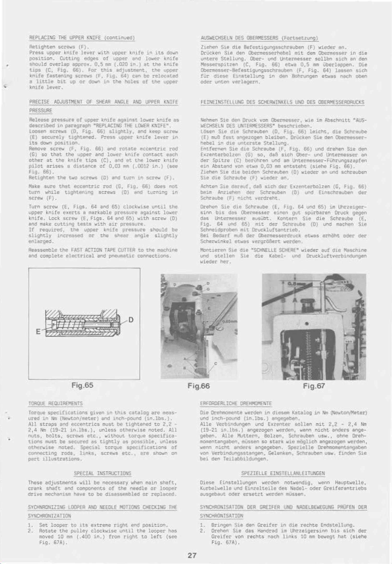
•
REPLACI!lG
Retigh
Press
ten
uppsr
THE
UPP£,R
screws
kntfo
position. Cutung
cohould
t1ps
~1fe
o
kn1fe
(C.
fastening
llttle
lever.
overlap
Fig.
bit.
opprox.
66).
acr.4
up
(F),
lover
edges
or
-,::MFE
witn
0,5
For
(F.
dONn
{¢ont.inutd)
upper
of
upper
mtl
{.02'0
this
adjuatl'!ltmt.
Fig.
&4)
1n
tne
hOle"
kni(c
oncl
1n.)
c~
).n its
lower
~t
the
the
be
reloeated
of
the
d()O,jn
knife
knife
vpcer
upper
AUSWECHSEUl
z~ehen
Orucken
u
ntere
McsserSPltzen
Oberr.esser·Befestigung
fiir
dtt'$e
odez-
unten
OES
Sie
die
Sin
dtn
Stellung.
hnatellung
werlegern.
Q8ERXESSERS
Sefcstlg
unosschrftuben (F)
Obarmcsscrhebel
Ober~
(C.
fig.
vM
66)
ssc
hreub~n
in
Unt.crmesser
den Bohrungen etwas
(Fortsetzung)
mit dea
ttk&
0,5
mn
(F,
Fig
vicdcr
an
.
Ober.csaor
soll
bn siCil
Ubcrl~ppcn.
. 64)
las~on
n.~ch
in
an
die
den
Oi.e
slch
oben
PRECISE
AO.nJSTI<EIH
PRESSURE
Release pressure
doscn.bed
Loosen
(E)
lts
down
Re.
-.ove screw
(C)
so
other
pilot
hg. 66)
Retighun
Ka~e
tum
screw
Turn screw (E,
upper
knife.
in
screws
securely
pOSHt.on.
that.
at
the
arise&
.
the
sure
that
while
(F).
knife
lock
()lregrlph
(0,
t:Lghtened.
(f,
t.ho
~ni
a <hs.tenee
two
tlghter
eJCert.&
scrow (E,
and make cutt1ng
If
required,
s.lightly
the
incn'&ted
enlarged.
Aeasse;;ble
end
COliiPlete
the
FAST
electrical
0~
SHEAR
of
upper Knt!e &gl•nst
•ftiPLAClrr«J fHt
Flg.
66)
slightly,
Pre$$
t1g.
66)
and
upper and
fe
tips
•_.crews
eccentric
ng
hgl.
64
& markable
Fi
t~sts
upper kn
or
ACTION
lwer
(C) ,
of
0,03
(0) and
:-od
screos
and
65)
gs.
64 and
wi~h
air
ife
me
TAPE
and
pneum.'ltlC conne
ANGLE
AND
lowe
LOWER
end
upper
rott\te
and
(G,
prcMure
pre~sure.
shear
CUrTER
kntfe
eccentric
k
n1re
ot
the
mfll
(.0012 in. }
turn
1n
Flg.
(0)
ond
cloc~wise
again
65)
with
preas.ure
engle
to
UPPER
r kntfc as
IOUfE•.
keep
lever
contact
lower
screw
66)
does
turning
until
st
screw
should
slight!~
the
r.:3Ch1ne
ct1
ons.
KrllrE
sere-.
tn
rod
each
knifo
(see
(f).
not
in
the
lov.•cr
(D)
be
F
EINEIIISTEllUI•G
loehmen
h~CHSELN
...
Osen
(E)
hebel
Entfernen
aJ8
Sio
Sie
il'l
DES
fest
d1e
den Druck
UN1ERK£SSERS•
dto
Schrauben
a~zogen
untc:rste
S1e
dtc
Exzenterbohcn
der
Spitzo (C) ber\lhren u
ein
Abstand
Zlehen
S1e
die
Ac.ht.e1"1
be~
Schra~be
Annehcln
Orehen
sinn
bis
das
Unte['IN.JSM.tr
fig.
Schneidproben
Bei
Sctterwinhl
l'bntt.eren
und
v
G.;
Bedarf
stellen
ieder
von
Sie
d10 bcacten
Sehrtvbo (F) v1eoer
3to
dataut
(F)
ntcht
S1c
dle
d8fl
c->erme
und
6~)
•tt
d
etwos wergrOAert.
S1t
cht
S1e
her.
DES
SC!iER>IIII~lLS
vom
Obermcuer,
UNO
beschr1eben.
(D.
Flg.
66)
bleiben.
$1:ellung.
OrUclcen
Schraube (F, F19. 66)
(G)
so,
daB ai.ch Ot>cr- vnd
nd
P l.htCl'mc.s
etwa
0.03
twn
entttcht
Schravben
(0)
wiodcr
an.
da8
sic:h
der
Euenterbolzen
o.::r
$chrauben
(0)
verc!reht.
Schraube (E,
sser
avsUb't. Kontern
mit
Orucklu!tantrtub.
der
Cbermesserdruck:
einon
der
Ftg.
64 und 65)
gut
Sie
Schreube
wrovn.
'"SCH'IEllE
die
SC,.EAE'"
Kabel· und
wied
DES
OBERMSSERORUCKS
w:ie
t.
Abschn1t.t. "AIJS-
leicht:,
Sie
und
ser
(S:l.ehe !=ig,
IJI"'d
spU
rbaren
die
(0)
etwes
er
Oruckluf~vorblndungen
d1e
Sc:hreobe
oen
O:ler.Kser-
drehen S1t den
IJ'ltermenor
-Fijhrungszuptcn
68)
an
v()(l
•chrauben
(C,
Flg.
Ei.nsenreuben ck!r
im
Uhrzo1ger-
Druck gcgen
Sc
hraubo
on
.
66)
(E,
und mechen S1e
erhiiht
au-f d1e
ooor
der
~schine
E
Fig.
TOR!lUc
Torque s
ured
All
2
,4
nvts,
tions
ot.herw1se
connecting
port
These <Jdjustmenta
crank
drive
REOJIR£HE"S
pect!lcetlons
in
lim
(Newton/meter) ar.d
straps
N'n
und
(19~21
bol~s.
.ust
scrowt
be
secured
not4!'CI.
eccentric
1n.lba.)
rods,
lllustra~ions.
shaft
mcchanls~
and compOnents
65
given
etc
as
Spccaal
hnies,
SPECIAL
will
~ve
to
in
th1S
~nch~pound
s must be
,
un
less
.,
wi~hou~
tigh~ly
ttghtened
oth4!1rwlSe
as
torque
sCI"eefs
etc., ore
IIISTAUCTIONS
bo
necessAry
of
the
be
d~sass~led
cetalog
are
meas~
(in.lbs.).
to
2,2
noted.
torque
possible,
spoc~hcetions
when
needle
speci!ica
moin
or
or
replaced.
All
unless
of
st'~Gwfl
on
shaft,
looper
•
Fig
.66
EAFORnERL
Cie
Oretnoaente
und
.lOCh-pound
Alle
(19~
21
geb
en.
mOdlent.angabo.-..
wenn
nicht
von
\e.rbil'lldvnfpstangen, Geler.k.en, Schrauben
bei
cro
Olcse
Kurbelwelle und
ausgebaut
ICIIE
OAf.-NTE
\oerde.-.
(in .lbs
Vcrbindungen und
1n.lb8.)
Allo
engezogeo wcrd
Muttern,
"'VSSen
enders
angegeben.
Te1lobtn dungen.
SPEZIELlE
Einst•llungc
n
Eintelt..eile
oder
orsetzt
Fig.67
in
d1eS611
.)
engegeben.
Exzentcr
Solzen,
so
stark
EINSTELlANLEITUNGEN
wetden
werden mussen.
Ketalog
sollen
on
,
we-nn
Schr8uben usw. , ohno
Wlt
moglich
Soonelle
notwoodig,
c!et N1dol-
odet
in
~
(f'lo·~tonjMeter)
mit
2,2
• 2
,4
nicht
undors
angezogon
enge-
Oreh-
\<o-erden.
Orehllonlent.eog.oben
LtSv.
finden
wenn
Haupt
wol
G'reif•renttiobs
nn
S1e
lc,
SYDNn"JlZIA(;
SYI;(;
...
~IZATlO•·
1.
Set
loopor
2. Aoto;te
lliOv
Fig
ed
.
the
10
6711)
UXPEA
t.o
pulley
mm
(.
.
/rtJIJ
1.
ts
exue.;e
clock.visc
400
l~EEDU
nght
in
. ) from
f()JlO'.S
end
unt1l
right
01ECKOO
position
the
looper
to left
1
1.1(
.
has
(soc
S\'IOAl'IISATI!l', 0U1
SYNOiAO~oiSATION
1.
Br
2.
Crehen
Gn
Fig.
27
ingen
ufor
67A).
S1e den
SLo
des
von
rechts
GllEI~ER
Greifcr
Hanclrad
'.0
1n
in~
ouch lln\:&
liAOELBa.'I'GU'lG
d1e
rech~
e
Endstellung.
l,ttrzei
gers1
10m
bew
nn
bi8
cgt
PAOfEN
aich
nat
(aiehe
OER
der
Page 19
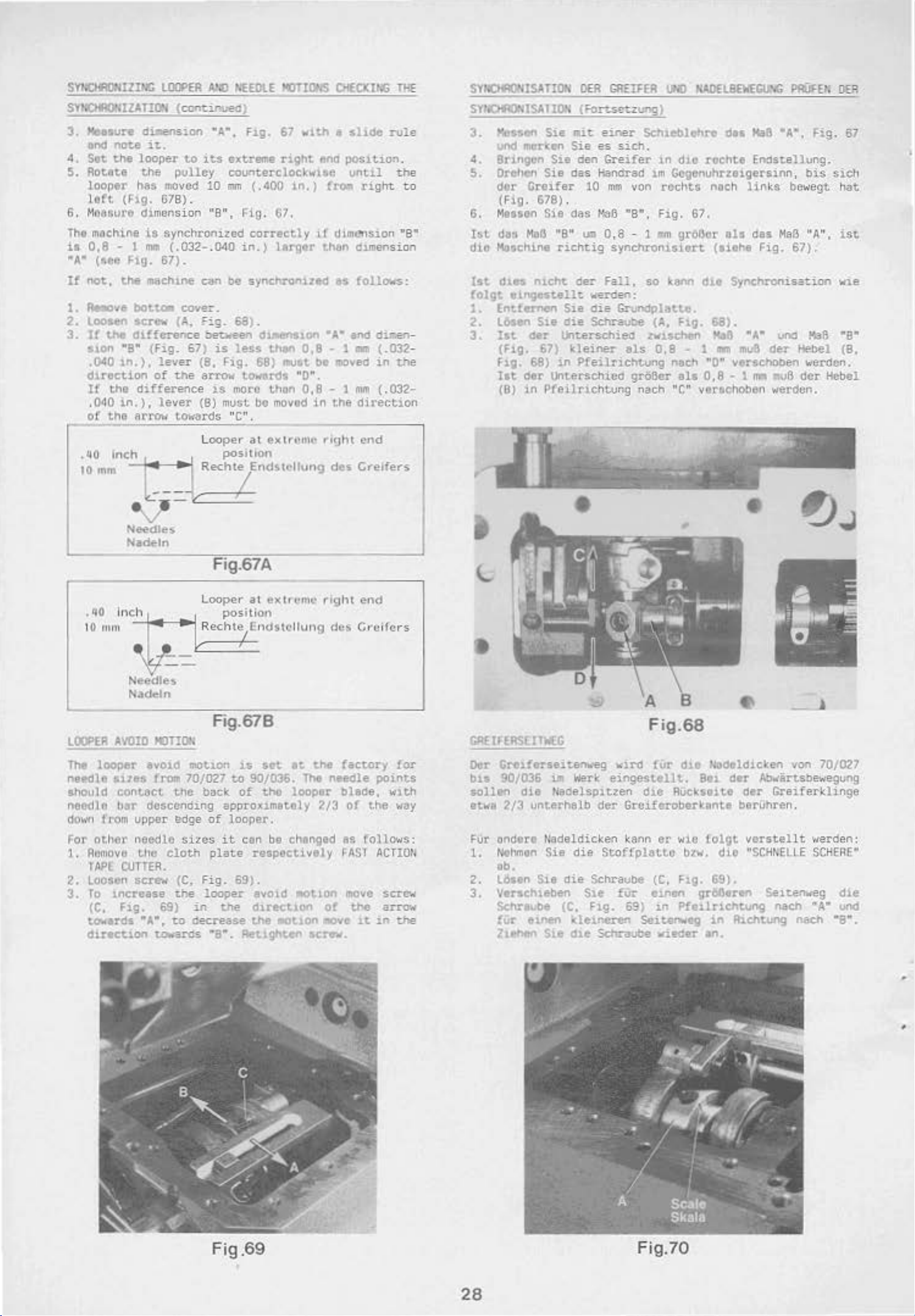
SYNCIRit<IZIHC
SYN()R)NIZATION
3.
~sure
and
note
4. Set
the
S. Aoteto
loopn
tart
(Fig.
6. M06Sute
Tho
mochine
h
0,8
• 1
•A•
(aee
If'
not,
the
1.
,._,..,e
LIU'EA
dLnension •A• .
it..
looper
~he
has
G7B).
dimon
is
mM
ftg.
67) .
1118dnne
bOt
toll
2. loosen screw
3.
II
the
d1ffcrence
tton
•s•
(Fig. 67)
. 040
1n.),
dlroction
If
the
.040
in.),
of
the
.
&10
inch
10
mm
lever
of
difference
lever
arrow
~
All)
NEEDLE
(continued)
fig.
67
to
1ts
e~treme
pulley
mOved
sion
synch~on1zed
(.032-.040
counterclockwise
10
mm
"8",
Fig
in.)
c&n
be synehronizftd
right
( .400
. 67 .
correctly
larger
cover.
(A,
F~g.
68).
be
u.een
is
(8,
the
arrov
is
(8)
towards "C",
Loop
Rech
diftlons1on •A•
less
Fig.
68)
tow&rds
mOt'C
must
b•
e,.
at extn
position
te
Endstt•llung
than
thon
movod
MOTIONS
wi~
~na
in.)
fro.
tf
thM
0,8
- 1
must.
be
"0".
0,8
- l
.in
the
'rllt\
rig
des
CI<EC
KII.ll
1
sltde
position.
unttl
right
dim
cn$ton "8•
d1t11en
as
follows
and
Gm
IDDved
mm (.032-
directio
ht
end
G,-elfen
THE
rule
the
to
sio
dimen-
(.032-
in
the
SYI.tHAOOISATIIl'l
SY!OR)NISATIG'I
3.
".cs$on
und
morken
4.
8rLngcn
5.
Orehen
dor
Greifer
(Fig
. 678) .
G. Mtllctn
lst
das
MaB
n
:
n
die
1st
folgt
1.
2.
3.
"''chine
dUt$
rncht
01ngestellt
Entfernen
L.bson
lit
(Fig.
F1g. 68)
Itt
(B)
Sie
der
67)
der
in
DER
GAEIFEA
(Fonseuung)
Sie
ai't
einer
Sie
es
sich
Sie
den
Greifer
Sie
das
Handrsd im
10
mm
Sie
dfiS
~6 •a • ,
"8"
tm
0,8 - 1 fl'tll
richtig
der Fall,
Sie
die
1¥tterschiea.
kleiner
in
unterschicd
PCeill"ichtung
synohronistort
wercien:
die
GrundplatLe.
Schr-avoe (f.l,
Pfeilrichtung
....0
NADELBEIOEGU'IG
Schleblchre
.
in
dlO
Gogcnuhrzoigersinn, bis
von rcchtG nach
Fig.
groBor
so
kenn
Flg.
tv1sehon
als
0,8
...
noc.h
gr68er
nach "C" verachoben werdcn.
els
d11 188 •A•.
rochte
67,
{siehe
dlo
68).
1116
1
"0" verschOben "''erocn .
0,
Endstellvng.
links
all
des
Fig.
Synchronisat
•J.•
.-n
mu6
der
8 • t m
MaB
ond
_,a
PflUFEI
b
.
~ig.
e~o.•e
gt
"A"
,
67).
ion
Ka8
Hebel
der
Hebel
OER
67
nc
h
at
ist
vie
•s•
(8,
h
• 00 I
tO
rnm
LOOPER
The
needle
ahould
needle
do.,m
For
1.
AVOID
loo~r
slzt.s
contoct
bar
from
other
Amnovc
JAPE
2. Loosen
3.
To
1ncrease
(C,
Fig. 69)
towards •A•.
direction
~Jd
Needl~$
Nadetn
Fig.67A
Loope,.
net
..
k R
ech1;Endstc
Needles
Nadeln
Fig.67B
MOTIOI<
evold
descendin
upper
needle
t.hc
OOTTER.
sere~
mot~on
frota
70/027
the
bGck
g approximetoly
~ge
of
sizes
cloth
to decrease
to~o;a.ros
(C.
Fig. 69}.
the
in
olate
looper
·s·.
at ext
posH ion
u
sot
to
90/036.
of
thO
looper.
it
c
an
be changed
respectively
e~oid
t.he
direcUon
the
-.otlon
~tlgtrten
reme
llung des
at.
the
The
looper
2/3
..ot1on
screw.
right
factory
needle
blsde,
of
as
FASl
move
of
tl'le
.ao'le
_j
end
C,-cifcrs
for
points
with
the
vay
follo·..,s:
ACTIOU
screw
arrow
it
in
t.he
•
GRt'lflRSEIIKG
Dor
Gr~nferseit.ern.reg
b1s
90/036
soll~
etwa
2/3
FUr
ondere
1.
Nohmtn
ob.
2.
L6sen
3.
Verschleben
Sehra"'be (C.
fiJr
l1ehen
ill
die
Nadelspitzen
unterh&lb
Na
deld
Sie die
Sie
die
etnen
!he
werk einsest..ellt... 801
de1neren
dl.e
vird
der
Gro1feroberk•nte
icken
Sle
kann
Scoffplattc
Schraube (C.
fUt
Fig.
Schraube
Fig.68
fUr
dlO
·
~deldicken
der
dle
RUcksuto
er wio
folgt
bzv.
Flg.
tlflon
69) .tn Pft.J.lrichtung nach
Se1.tenw~
vieder
gr~ertn
•n.
dio
69).
in
Richtvng
der
berVhre
verstell
·scH~EL.~
von 70/027
M>llirubewegung
Greiferklinge
n,
Seitenweg
t ·.rerden :
E
SCHERE•
die
•A'"
vnd
nach
•a•.
Fig .69
28
•
Fig.70
Page 20
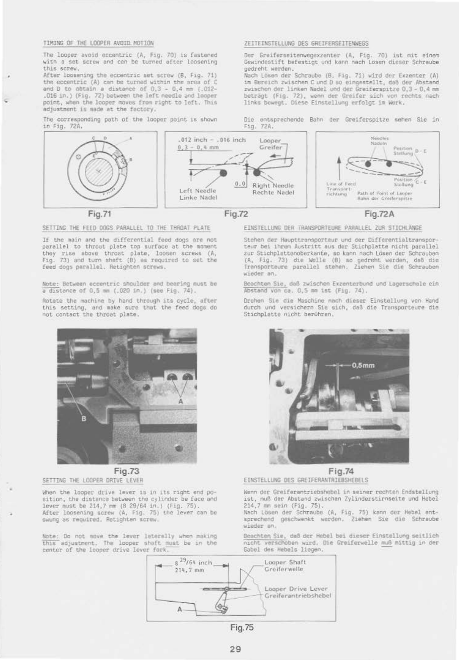
•
TlHlNG
The
OF 1 HE.
looper
w)th a set
thiS
scre-N.
After
the
and 0
.016
point.
loosening
eccentric
to
1.n.)
when
adjustQent
The
corresponding
in
Fig.
72A
looPER A\.'0!0.
avo1d
eccent
HOT
ric (A.
ION
screw end can be turnod
the
eccentric
(A)
can
be
Obtain • distance
(Ftg.
the
15
72)
looper
m11de
between
IT'IOVC$
at
the
set
turned
of
the
(~
factory.
Pilth of thP.
.
•
Fig.
70)
is
ait.er
•crew
w1~hin
0,3 -0.4
left
{8,
the
needle and lOOPtr
r:a.ght w
looper p01nt
• 012
o. J -
fastened
loosening
Fig.
71)
a~a
of
C
-, ( .012·
left.
n
l~
l.S sho-Hn
inch
~
.014
inch
0, 4 mm
I -"'7,
r..___,
7~.P_.,__<
/
Z£IT£IkSI£llUNG
Oc
r
Gretterseiten~o•cgc
GeHindc
sttft
0{$
GAE1FEAS£ITEVo~Gs
x
~ent.er
befestigt und
gcdrcht werden.
Nach
im
Bcrc1Ch
Lo~en
der
Schraubc
lwischen
C
und 0 so
zwischen ~r lin.ken 1•adel
bet.ragt
links
Die unt10rechende
Fig.
(Fig.
bewe
72A
.
lool)er
Crf'•fer
72),
01ese
~
illent'l
Einstellung
Bahn
r--
1 . '
,._
(8,
'-""<1
dcr
der
(A
kenn
11g.
etnges~
c••r
Cl
Greife
-
:
~
,
Fig.
70)
nac
h l Oscn
71) vird dPr
ellt
,
Greiferspit.ze
lfer
sich
erfolgt
~
rspitze
Hlt
mit
einem
d~080r
da6
von
~~rk.
Schraube
lx1enter
d~r
Abstand
0,3-0,4
rechU
$6hen S
nach
ie
(A)
a'll
in
·~'
SEITTNC
If
par
they
Fig.
feed
lfOte:
a
dutance
Aota
TliE
tl',e main and
all
el
to
n
~ e
73) end
dogs
pe~ellel.
se~een
of
te
the
l.h:i s setting,
not
contact
Fig.71
HEO
DOGS
the
dlfferentiol
throut
Abovo
turn
ecccnt.t'lC
0,5
m~Chtne
the
ond
throat
plate
t-hroat
shaft
RctJ.ghten
ll"--
(.020
by
make
PARAllEl
top
plate,
(B)
••
shoulder
in.)
hand
through
sure thot
plate.
TO
THE
TI!IIOA
food dogs
surfocu at
looGcn
requ1.rcd
$Crt~.
end
beeriog
(teet
Flg.
tts
Lhe
Left
Nee
Linke Nad
T
!hall
are
the
moment
screws
to
set
.ust
1~}.
cycle,
feed
dogs
dle
not
(A,
the
be
after
do
t
L""'
,;,1
I l'f'tl !Oh·ll\i""' C (
T r ,, ,
~1)1'1
el
r«
Fig.72 Fig.72A
E!NSTEUI.f4G
Stehen
teur
bei
1ur
Stichplottcnobcrkante,
(A, l=lg. 73}
Trensportevrc
w1eder
Seacnt.en S1o,
AbstanO
Orehcn
durch
Sdchplattc
uno
OER
iRA.\ISPCIRTf~£
der
tl\lupttransporteur
1hrum
Austritt
d1C
parallel
an.
d&8
zvischen
...
on
co.
0,5 • ist
Ste
du
Maschine nttch d1.eser Ei
versichern
nic:ht berUhren.
aus
Welle
stehen,
Sio
I
111""11 1'4olh
dor
so
(8)
llilf>tl
t>ARAlLEL
und
dcr
Stlchplatte
kof'ln
na¢h Losen
10
gcdrcht
Zl.ehen S1e d1e Schraubcn
Exten~rtM.Ind
(F1.g
. 7t:).
sich,
daB
die
1"\)•ll~)f'l
011
f'oont
Qf
l
doH
Zlfi
'~''l'~r
Crc-!lc.H">oll~
STICJ•
ANGE
Olfferentioltrilnspor-
nicht
werden, daB
und
Lage-rsC~>ole
nstcllvng
Tr
onsoorteure
dtr
porallel
Schx
·aubcn
von
Hand
d1.C
ein
die
SEITING
When
the
siti
on.
lever
After
s·oiVI'Ig
r10te:
trns
center
~r~vst
loosening
as
Oo
adjustll'lent.
of
THE
lOOPER
looper
the
dis~unce
be 214
required.
not
1110ve
the
looper
Fig.73
DRIVE
drlve
,7
screw- (A.
lev
between
mm
(8 29/64 in. ) (1-ig. 75) .
RctlShten
t-"te
lever
fhe
looper
drive
lEvtA
er
tho
fig.
serlhoi,
lever
is
1n
cy l
7')
lat.eully
sh.IJCt.
for
1ts
right
1nder
t.hc
must be
:c-
.-
_ 8 29/Gll j,,c:h
end po
be faco ond
lev
er
can
when
ea•n.n;
in
21tt,7mm
A
bo
tM
E!NSTELLUNG
We"n
dcr
ist,
muB
21.d,7
Nach
sprechend
wi
ed
tMI
LO:;en
er
Be8Chtet\
n1.cht
Gabel
___..
d~s
)
Fig.75
Fig.74
Dt$
GREIFEAAnTRIE8SHl6ELS
Greiferan~ricbsheoel
der
Abstand
t,(lin
(Fig
der Schra
gesch~~nkt wcrd~n.
.
z·•u.SC
75).
ube
an,
S1e.
da3
der
Hebel
venchoben
wlrd
_ Ote
Heb•ls lJ.egen. -
LOO
I,Or'
Sha
(t
Grt1!rurv.ellc
l.oop(!r
c,.-clfer'Otntr.ebs.hebel
0.-ive
Lever
1n
se1.ner
httn
lylind
(A,
119- 75) kano
liehen
bel
d1ese:-
GH1f•rwelle
rcehten
erst
irnseitt
Sic
Einnellung
MVB
£ndstellung
und
der
Iiebel
dlt
IB1ttl.g
Hebel
ent-
Schraube
SOltlich
1n
der
29
Page 21
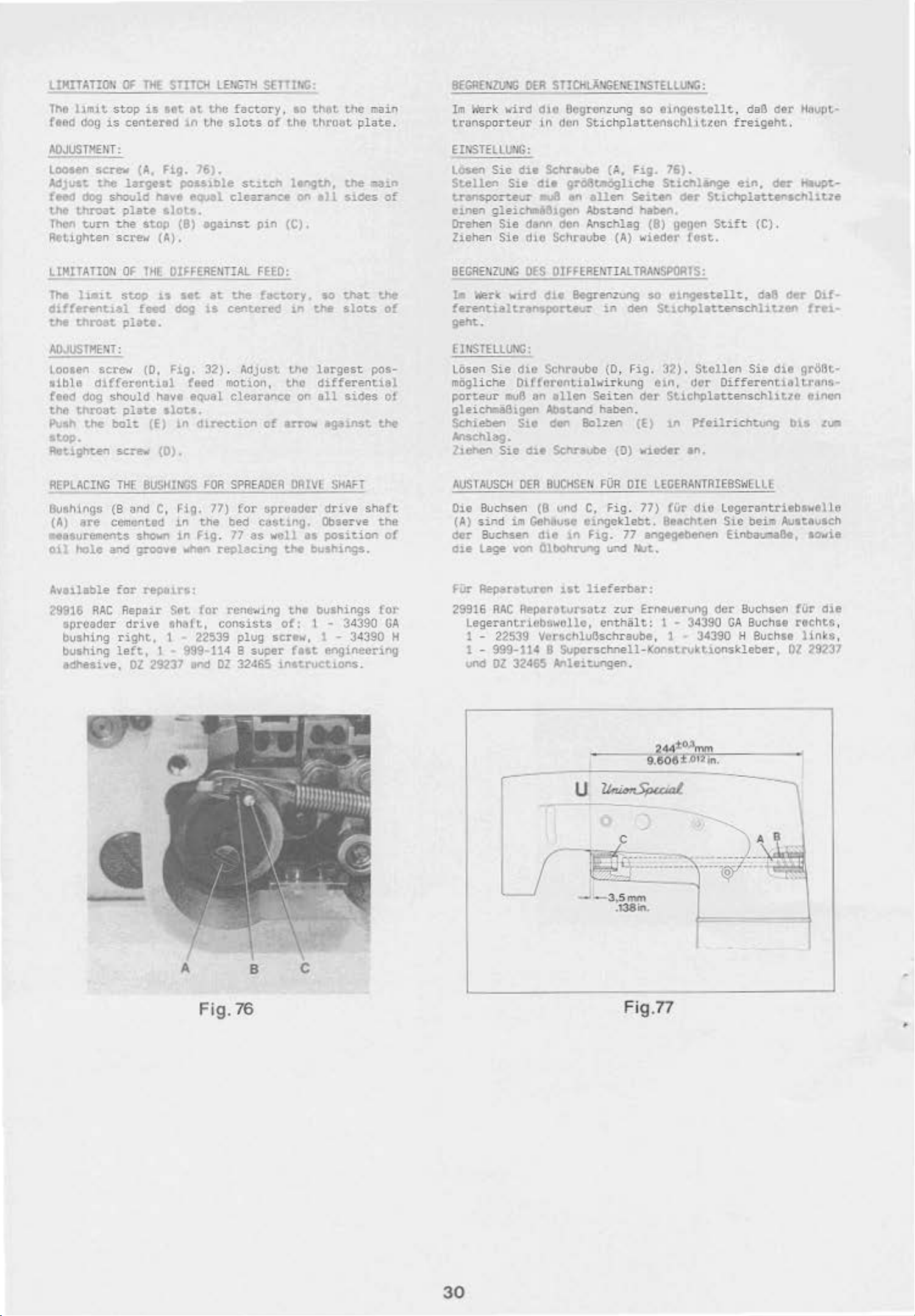
LIHITATIO'I
The
llm1t
ftod
dog
is
0<
THE
stop
is
aot
center~~
STITO<
et
1n
the
LE!IGTH
the
hctory.
slots
SETTliiG
ao
of
the
that.
throat
tho
plate
main
8~GREr;l\J'IG
Im
}.'erk
.
transporteur
"Wird
OEA
ST!CHI.A.'IG£r;"UIISTELLU>IG'
dio
Ucgrunzung
in don
Stichplattenflchltttcn
so
eingostcllt, daB
der
freigeht.
Hflupt-
ADJUSTHENT'
loosen screw
AdJUst
feed
the
Tllon
Retighten
LlHITATION
The 1
dlf!erentJ..al
the
ADJUSTMENT
Loosen
tible
teed
the
Pu11•
stop.
~tl.ghum
REPLACING
the
largnt
dog
should
throa~
turn
plate
t-ne
screw
OF
i•i
t
stop
throat
plate.
'
SCl'e'H'
differtmtiul
dog
shOuld
thro.at
the
plate
bolt,
sc:-ew
THE
(A,
Fig. 76).
poas10le
have
e~l
slot.~.
stop
(9)
(A).
THE
DIFFERENTIAL
u
Itt
feed
009
(0,
Fig.
teed
havt eqvat
slotl.
(E)
1.n
(0).
BUSHINGS
st1.tch
cleazance
agains;;
pin
FEED'
at
Ute f&etory
is
centered
32) . Adjust tho
motS.on,
clearv~oo
d1.reet1on
FOR
of
arrow
SPREADER
lqth,
on
all
(C),
so
1n
the
largest
tho
differential
on
ell
agnnst
ORIVl
the
s1des
that
slots
sices
SHAFT
cun
of
t.he
of
pos-
of
tho
E
INSTELLU>IG'
lOsen
Stellen
traosport.eur
einen
Orehen
Ziehe.n
BEGRENZUNG
Ill
ferentialtl"'I\$PQt"t.eu!'
Sic
d1e SChreube (A, F1g.
Sie
die
gleichm&&lgen
Sie
dann
Sie
dlo
DES
)(er-:C
wlt'CI
gro6t-oghche
~
en
Abstand
don
Anschlag
SchriJIJb
OJFFERENTIALTRANSPORTS'
<lie
Begrenzung
geht.
EltiSTELlUNG'
LOsen
mtigliche
porteur
Sie
die
Schraube
Oifforcntiolwirkung
moB
~n
ellen
gleichma61gen Abstonrl
Schieoen
M$Chlag.
ltehen
AUSTAUSCH
Sie
S.a.o
611
OEA
den
Bolzen
Schrtvbe
BUCHSEN
allen
Seit.en
haben.
(8)
e (A) wierler
so
in
oen
(0, Fig.
etn,
Seitan
haben.
~OR
(0)
DIE
der
(E)
Wledoer
LECEAAIITAIEBS>~ELL£
76).
Sticr.lenge
der
gogcn
e1n.
dtr
St1ehplatt.enschht.1e
StEt
(C) .
fest.
Gll'lgCStell't..
da&
Stlcholatunschliuen
32).
Stollen
dor
Sticnpla
l.fl
P!eilrichtung
Sie
die
Oifferentifll
ttenschli
an.
Hlupt.-
der
Olf-
frei-
gr~Bt.~
t.rtlns ..
tze
etn~>n
bts
.~:~
Sutlhings
(A)
ne
(8
cemcnt.od
,.esurements
ot.;.
hole
and
~vnlable
29916
sproade
bushing
bushing
edhesive,
RAC
!'
for
Repair
right,
left,
"nd
shown
groove
repatr&:
drive
Ol
29237 end
C,
rig.
77)
in
the
bed
in
Fig.
71 8$
..
.,.,f'!n
reolac.1ng
Set
Cor renc-.,ing
flht~ft.,
consists
1 22539
t
999-114 8 super
DZ
for
spruudor
cast1ng.
well
tM
of:
plug
screw, 1 - 34390 H
32465
inatruct1ons.
Observe
us
bushings.
the
bushings
1 - 34390
t'llt
drive
posi~ion
shaft
the
of
for
GA
enginecnng
Die Buchsen
(A)
sind
der
Suchsen dif! 1n
ote
lage
Fiir
Repa~tvren
29916
RAC
Legerantriebtv:ollc,
1 - 22539 VcrachluO.schraube, 1 -
1 -
999-U4
und
DZ
(0
und
C,
im
Gehftuse e1ngek
von
OltlOhrung
1st
Repar3t.ursatz
B
Superschnell·Konstru
32465
Anleituogen.
fig
Fig.
u.-.c:l
lief
erber
zur
enthiilt:
. 77)
lebt.
77
angeg•benen El.nbauaaO.,
ttst.
Erneuerung
-~
!Ur
Beachten
:
1 • 34390
die
Legerantri
Sic
der
GA
34390
kt
lonsk1eber,
.
___
:)
ebs-.elle
beim Autteuseh
sovie
Buchsen fi.ir
Buchse
H Suchse li.nlts,
die
rechts
,
02 29137
_~_
8
A
F
ig.
76
c
~=-··
--3,
5~
.138tn.
-··-~---~
Fig.77
•
30
Page 22
ORDERING
REPAIR PA
RTS
BESTEllUNG
VON
ERSATZTEilEN
lllUSTRATIOl·S
Thu
cot.olog
rcpau·
tho
•
seen
On
o
ports
~cchanism
i"
tho
ptJgc
lhting
scriptions
particular
t..
...Jbt.rs
only,
1n
be
lltttd
..-d
the
11lus:ration.
"sed
1n
•n
Component
ntshea
doscr1
for
pt. inns under
osuembly
At
tho
b&ck
lndox
facilit~tc
when
of
only
has
. Exploded
thctr
actv
opposite the
o£
t.he
cmd
v1cw
in
the
r>erely
ordering
th~
second column.
parts
repairs
.
of
the
oll
parts
locating
t.h.C
part
been
are
al pos
arranged
vie.,s
s
ho~o·n
so
ition
to
of
thut
in
SlmP1lfy
vor10vs
tho
t.ho
GC'.,ing
illustrot1on
p,arts
the
be1ng
hnt
indicate
of
with
n
v:~ber
of
their
pioc••
part
roQul.l'Cd J.O
shown.
col'*'
Reference
parts.
af"t
the
DOI1tl.Ot\
nullbfl's
A.lWI)'S
reference
"'"
the
sub-assemblies which can be
are
indtC.ateCI by
the dcsenpt10n
cata
log
will
sha.m
the
n~er
in
this
illustration
in
known.
indenting thei
of
bo !ound
cot..olog. This "'·
ond
ordering
sections of
ports
vlll
numbers,
aay
b-e
mac
hine
be found
de-
.
the
nu:---beN
of
that
part
should
part.
never
nu;bcr
fur-
r
the
main su
.a
num
b-
erical
ill
desc~iption
ASBilOO><GEN
Oiesor
stcllvngcn
einzclnen
Einzolt.CllO
K~talog
'
"urd
zv
vereinfachen.
Grvppen
1n
Oer tl8hnaschine. Aut <for
gegonllbol'hegenden
Teile
zeigten
Olt
Ulgen
ut
wenott.
l"llttt'l
Ettlzelttu.le
llO(~rt
sehrotoung
mit
T011nvmmern,
8ildousschnitt benOtigten
~
•"
dcr
lechghch.
. Pos1
tton~m
1o0trden.
Sp.illte.
\'e~
von
1o0erden
kOnnen, sir.d durch E1nrOcken
unte
rhalb
gckcnnlotchnet.
Am
E"dC
des
Ketalogs
sOmtllchvr
das
~ffl.~dcn
Tello~u~or
1m
Katalog
de~
bCk3nn~
e zusa:'Yflengestcllt,
um
ExplOBionszeichnungen d
des
~echaniamus
Seite
befind
8
esc
hreibungon
ot
aich
t019en
oln
unO
Anzohl.
erst.en
w
l(oQpletttellCn,
Sp.elt.e
das
Te1l 10
dUrfcn
der
befindet
be1
felltOestellungen
S1e
1P!M"r
Bcsehr01bung des
sich
dargestelltor
111~
Pout.on.snur:mern und
der
Abbi.ldung
ate
Ttilet'l~r
Cite
ell
e1n Nummernverzeichnis
To1l0.
AbPildung und Boschro1bung,
ist.
Ersa
tzteilb
die
lage
der
Bildseite
verzeichnis
der
fUr
den
zu
nie
Ersatzteilo
ihrer
Kompletteilcs
Oies
erleichtert
~oenn
nur
der
der
ge-
hnden
ver-
.10
c:e-r
ge-
Be-
die
ecr
JHPOATAHT!
PART
CHIIIE
Qt,
All
M'IE.
FCR
(R)ERS.
OO.:.HTITY
loHICH
PART
PlEASE
REC)JIAEO
IS
OAllERfD.
It.CLLI)E
AJiO
PART
SmE
M.I'SER,
QF
M.:.-
VICHTIG!
!itii<ER.
OEN
BIDE
KASCHIHE.~.
G€Be<
OlE
SIE
TEllESfSCKIUBU'.C.
Ft.FI
AJJI;
OEN
AI.LE•
OAS
BESTEll\.O.QON
OlE
BEHOTIGTE
TElL
8ESTEUT
DIE
TEilE-
HEMlE
NIRO,
U.'lO
Af'L
31
Page 23
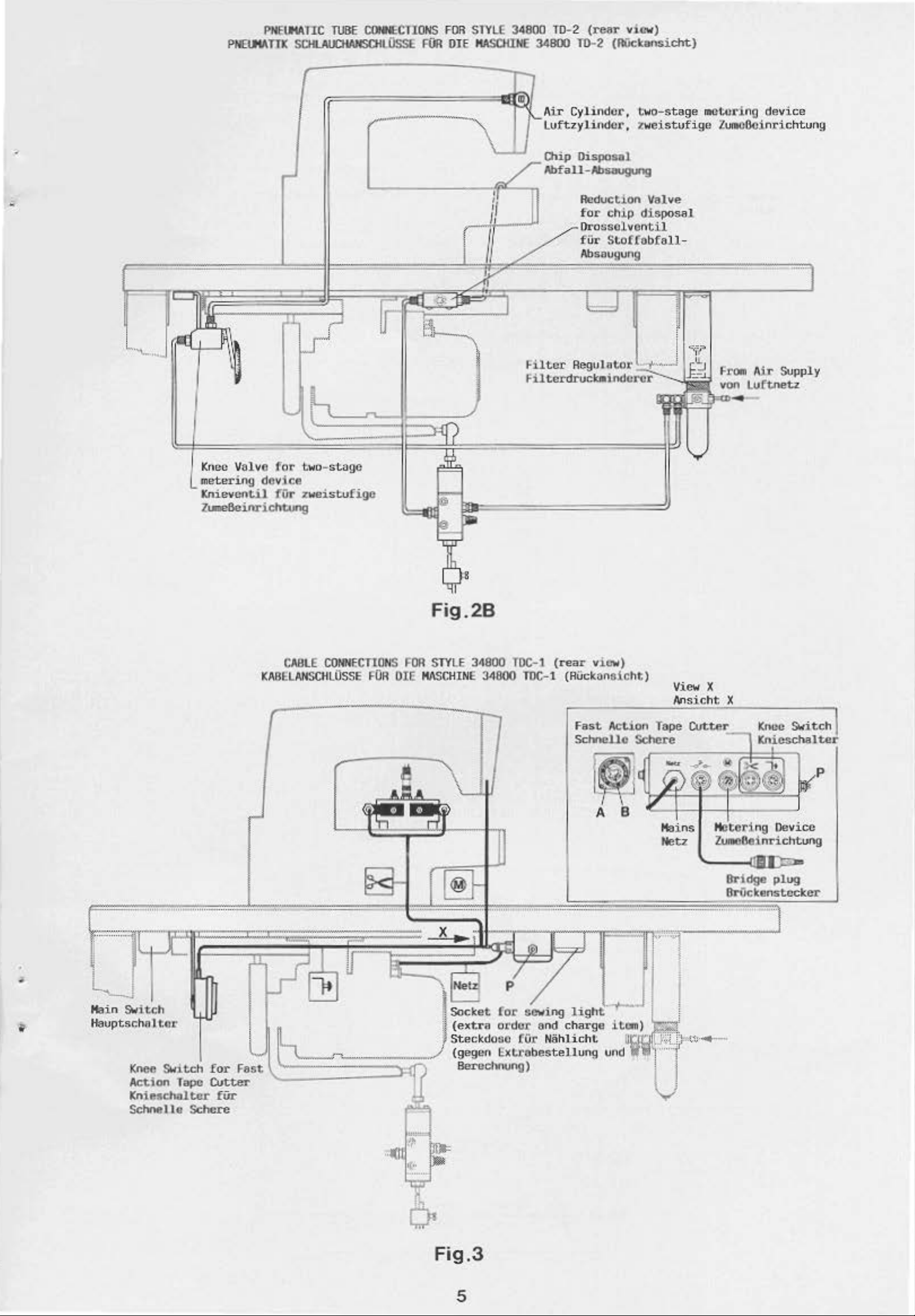
PNEI.IIATIC
PNEI.IIATIK
TUBE
C(Ht,CTIONS
SCili.AIJCHAHSOI
0ssE
FOR
STYLE 34BOO TD-2
FUR
OlE HASCIIINE
34800
(rear
TD
·2 (OOckansicht)
vi<"W)
.
"•
w
I
r.-:1
~I.
""
,u
u
<:!' I I
l I
itlf
[i;l
,
/
~
/
/ I
fW'
Cylinde
luftzylitu:tor,
~ip
Disposal
Abfall-Absaugung
Reduc
for
~
Hltcr
orossolvontil
fU<
_
Heguo
r,
two-stage
~
weistvfige
tion
Valve
ch.i.p
disposal
S
toffobfoll·
owo·
~
noetoring
tv="
device
ZuiiiOOcinric
FrOO>
Air
Suppl
von
Luftoetz
htu
ng
y
Kf1ec
valv
e
for
in.o
device
:~~il
fOr
z.....,&inriclltung
CABLE
KABELANO.cHLOSSE
"'
two-
stogc
zweistufigc
CONNECTIONS FOR
FOR
Fig.2B
STY
DIE
HASCHINE
r
X:
'U
LE
3~800
TOC·l
34000
TOC-1
(rear
view)
(Huckansi
Fast
Action
l~
cht
)
View X
Tape
Cut'"'"
~~re
~~
'--
K.I
'.OO
Switch
~~~te~
A B
Mains
Netz
Bridge
B'rOckenstcckcr
..
...
•
Ma
i n Swi.tch
Havptschaltor
Knee
Switch
Action
Kn
ieschaltcr
Schnelle
T:.pc
Sclwre
for
Fast
Cutter
fUr
l~==
==
==);fi?'
Socket
(extra
Steckdoso f
(gegen E
Bereci\OUng)
"
for
sewing
ut•d
or
Ur
xt.rebesteUung
liSihi
and
charge
N6hlicht
·-+--J
plug
.
Fig.3
5
Page 24
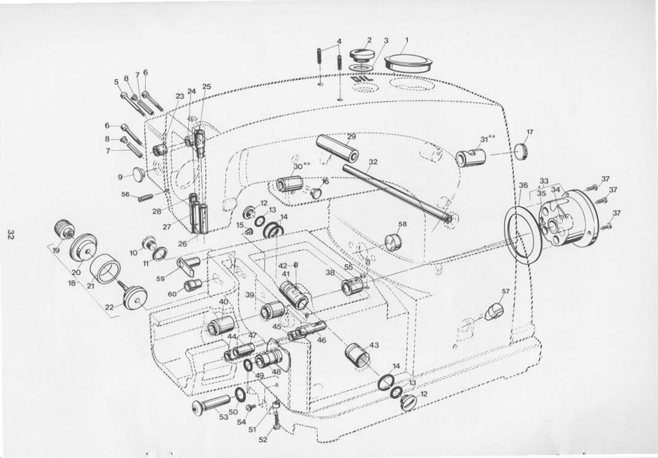
<.>
N
••
.......
•••
...
-·
..
•((--
I
I ' Q
/1
.
······
.
' Q
~
' ..
----·t:
" I ' '
'·
..
...
...
..
.
..
.........
...
"
....
·
····
····~;;
·
·-3
**
··
. ' .,d·
.
·
·..
...
.,
.
,,,,,,,
.
..
.
~
--
, I a
,,
·--
·1.,!.
-·····
"'
,,_.,~
.............
.
-
··
""'
·-······
"~
-~~
····
~
....
-
••••
·····-
·······
--.......... _ I
---
>·
.
··-
-
.Z~r··-·
.....
--.
----
• •
•• -•••
31**
@!J
-
I
I
1
>
.
..
I
j ·t
........
,
..
..
..
(i43
' . .
'
--
---
,.--'"
•"'
'
I
I
I
'
•
'
-
..
I
I
I
I
'
I
I
'
·-
...
..
--·
5,Y
I
.)
' J
'
.....
,,
.-·
()
' '
,
"'
"'. ,.
"".,..-
... -...
, .
••
,
•'
57!
.......
,,
....
,,,.
I
I
I
I
I
l
,
....
.
••
•
Page 25

8USHIM;S
8tJCHSHl
AAO
UNO
VfRSCHIEOHlE
HISCELL"HltJS Pll.GS
VERSCHLUSS·STOPFEN
•
Rf:f.lio.
Pos.Nr
•
1
2
3
4
5
6
7
8
9
10
11
12
13
14
15
16
17
18
19
:ro
21
22
23
2•
25'
26'
27
28
29
30"
31"
32
33
34
35
36
37
38
39
40
41
42
43
..
45
46
47
48
49
50
51
52
53
54
55
56
57
58
59
80
Part
.
TeH
999-212-5:ro
22733
56382 M
22994 l
95413
95401
96665
999-212·
999-78
99376
963~0
99347
999·211
999·211
999·212-062
999·216
22539
34393 0
95776
34393
34393
34393
97200
97207
34354
34354
51257
34847 8
34383 A
34390
34390
G 21657 X
34390
34390
96658
56390 l
22569
34390
34390
34390
34342
2289·1
34342 8
34336 c
34336 8
34336 E
34336
34336
999-211
999·211
34336
22874
34335
22829
963¢1
22839
G
50·434
34794
34763
34763
No.
Nr.
[
B
R
T
s
A
A
..
H
GA
OX
ex
8
0
A
A
AD
0
F
G
F
c
•
L
062
c
A
E
Ocsc-rtPtJ.on
Plug
Plug
Screw
Gasket
Set Scrow
Screw
Screw
Aoll
for
Spreader Drive
for
Spreader Drive
Pin
Plug
Plug
Plug
Screw
Gasket Atng
Plvg Screw
0-Ring
0-Aing
Plug
Plug
Plug
Screw
Plug
As.-ly
Knurled
Flange
Oi 1
Flange
Bushing
8oJshing
Needle
Needle
Presser
Bushing
~t
S<1ol
Fhng
lctL,
r19ht.,
8or
Ser
for
in
Bushing, upper
8vShing, lower
S.r
Bvshi.ng
Spl"e8(1er Or"ive
Spreader Drtvo Housing
in
Spr
eader
9vshing tor Presser Foot
Bushing
Bushing
Bushing
Crank
BuSt'l).ng
Roll
Gasket
Scr
Cranlt
Main
Kain Sh&(t Bushing,
Loopar
Se~
Looper
Feed
Feed
feed
Feed
Bushing
0-Aing
0-Ring
P~ssure
Shaft
...
srtaft
Shaft
Screw
Rocker
Aoc:tcer
Lift
Lift
left,
r1ght,
for
P1n
to~
Spreader Or1vo
for
Spreader
Tension Release Uvor
Bushi ng HOusing
Bushing,
Bushing,
left
aiddle
left
Or1ve
Or1
Shaf~
ve
Shah
Shaft
$heft
Shaft
Shaft
tor
Dlfferential
BushiOQ , rear
Bushing.
Bushing,
Bushing,
9ushing,
&,.shing,
Sleeve
Screw
COllar
Stuct
Plug Screw
Grocwed
P1n
Plug SCrtv
OJ.l
Sight
OJ.l
Sight
Svslnng,
S
ushlng,
G.ouge
Gauge
right
lift
for
fox·
cast-off
cast-off
Housing
Housing
DrlVO
lifter
r1ght
left
Feed Chenge
tlovsing
lever
Shaft
Drive
Asse~ly
left
nght
plote
Shaft
Shaft
front
plt~tc
Be&chresbung
Ver$ChlvBstopfen
Ver$chluBschraube
D1chtung
Gowindcstift
Schravbc fUr Geh8use tux·
Schr~vbc
fUr Geh8use
Lcge~entrieb
fur
Lcgetentrieb
Sp1nnhUls.c
VC>rtchlu&s-topfen
Vert.chluibtopfen
V.rlchlu6schraube
fliCh<hchtnng
VtrtchluBschraube
O·Rlng
O~Alng
Verschlu6stopfen
VerachluBstopfcn
verschluBschraubC
wrsct.h&topfen
l:o.c»lett
Aunc:tel.n:te=
Fl•nsch
OlChtring
Flonsch
Buchtte
Butht.e J"echts,
Buth50 oben,
Buchse
Buchse
Buc:t\le
Buehse
8uehsc
Bvch.!l.o
links, im
vnten,
fur
fur
Lege.rantrieb
fur
OrUckerfuftllfterhebel
bnks,
rechts,
Gohtiuse fUr leger
im
Gehiivso fUr
fU
r Nadolatenge
fUr
J4'adolst.enge
Ori.ickerfu65t.onge
fUr
legerontrlebsvelle
fUr Lcgcrontri.ebs•..;e
l.egerantnob
Buchac fVt SpennvngsOftnol'Ochse
Gehiu1o
fOr
K:u:rbeb.
•elltnbuchSc
Buchsa
SpenohOlse
Ol.Chtung
Schroube
Boehle
Buch11
Buchae
Greiferentriebswelle,
fUr Kurbelwelle,
fUr Ho.ruptwelle,
fUr
Havpt~elle,
hinten
lJ.nt&
Hittt:
links
Gcw1ndestift
Buchse fUr
Buchse
Buchse
8uc:h$e
a..chse
Bud'lu
0-A.I.rtg
0-Rl"IJ
DrutkllOlse
Schraube
8v~db01zen
\'crtchl
Greifcrantritb&'-'elle,
fUr
TranspOrtantriebswelle,
fUr
Transport.ant.rlebsvelle,
fiir
Tra'"lSporthvbwelle,
fUr Transport.hutlwelle,
fiir
OifferentlOltr-ansport.-VcrstellU<t~g
u8schraube
lyllnderkerbstift
Verschlu6schreube
Olaton<Jsevge
OlstoncJ.sauge
Suchso.
8uchso,
rechts
fUr Fodcnob1vgsplatte
links fUr
Fadenobzugsplat te
antriob
lle
lr:omp
vorne
rec:hu
links
1
ett
llnts
rec:htl
Mt.A~
Anzahl
I
I
t
2
2
'
2
2
1
1
1
2
2
3
1
1
1
1
1
1
1
1
1
1
I
I
1
1
1
1
1
1
1
1
1
1
3
1
1
1
1
1
1
1
1
1
1
1
1
1
1
1
1
1
1
1
1
1
1
I
.
• '«lTE: The
•• Replacement
bushings see
needle
cest.ing.
!ollo.ting
2991G
34354
3435.4 A
999-114
oz
29327
oz
29328
b.;:rr
buShings
Therefore
repeJ.r
RA
8
lnttructions
PIQI
30.
are
we
rec~
set
for
Repo
ir
Bar
Bu
fl.lli ngs,
Needle
Needle
Super
Ins-uv<:tJon
Insuvc:t1on
for
spreodcr
CO!het't.ed
encs
ren-!VU'9
Set
for
to
the
rencw
in
the
order
bushtng$:
J.n
g
consists
B8r Bushing, upper
Ou
Bushing,
fest
Engineering
dt~ve
lower
$haft
bod
the
the
of:
Adhes.1ve
Needl e
33
..
·~
S:EADITEH
Goftgetleuse
che
zu
Aoporo
huchsu,
SIE:
Die
Buchsfllt'l
einget:lebt.
frnet.~erung
bestellen:
t.u
r.silU
bc~tehend
der
zur
eucnsen
& nou
aus:
fUr
die
vu
e;pfehlen
folgen<ten
ctVng
lladelst.ange s.iod m
Otlhalb
Aepernursau
der
Nadolst.onue-
8uchso oben. fUr Nado1Gt8nge 1
8vchs.o
unten.
fOr
Nedebtt~nge
Suporschnell-Konstruktlonskleber
AnleJ.tung 1
Anl•ltung
Anleitvng
w
elle
z~
nehe Sei
Austausch
te
3-0
.
der
Buchsen fVt
legeranticbs-
filr
1
l
1
Page 26

62
~
61
.
...._
__
Remove collar
Stellrln
View
.
Ans1cht
in
beim
33
arrow
in
Pfol
when
moontlng
Montieren
d1rect•on
lrlch
tung
cntfel'nen
X
X
-
11
l
~
..
..
.
..
. . .
......
' }
.
des
0
(Pos.Nr.2)
der
Olleltbleches
ftul\
rechten
Buchse
Te•l
Tell
•.n
die An·
filr
Nr.l•l90
N,...
die
GA
~·
34
Page 27

H.ISCEllANEOUS
VERSOUED£N(
COVERS
AllOECKUNGEII
Ut.O
AND
TEllE
Dill,..;
DES
PARTS
OlSYSIEMS
Ref.
No.
Pos.Nr.
1 22585 8
2 34782 0
3 34382 8
4 34382 F
5
6
7 34894 A
8
Plrc.
Teil
34382 G
99242
61494 G
9 604
10
11 56393 w
12
13 34894
14 34894 8
15
IS
17
18
19
20
21
22
23
24
25
26
27
28
29
30
31
32
33
34
35
36
3? 96160
38
39
40
•t
42
43
..
45
46
4?
48
49
50
51 34393 L
52
53
54 999 196
55
56
57
56
59
so
61
62
S3
9!:1250
666·214
34831 c
22564 8
22513 8
3•39-1 c
3039-1
999·211
22894
30394 E
30394 A
30394 G
34394 F
22565 c
96866
999·212·062
34393
660
34393 N
22894 T
34393 8
34393 L
34393 F
22894
34393 c
34393 D
34393 A
22585
34393 p
22798
96150
34363 E
22528
999·160
99349
9~·211
34393
96276
34329
34382
999·?54
90710 A
9540G
95953
51294 z
~654
88
22899 A
No.
Nr.
8A
AD
·212
AO
~
CA
KA
D
8
G
J
Descr~t.ion
S<r""
Oil
Guide
Oiler
Cover
~sket
Plate
Screw
011
lube
Assembly
coll&'~'
Sctcw
t,'vt
Oil
Felt
Oil
Felt
Clamp
Oil
Guide
Scre~oo•
for
Oil
Tube
Tube Ol.tOht
Plate
S<rew
Plastic
Oil
O·Rlng
set
Plast.lC
011 Tube
Plast1c
Pl8$tlC
Plug
Dowel P1n
Plug
Oil
Oil
Oil
Set
Oil
Spring
Collar
washer
Pis~on
Pinon
Q)
1
Tube
Tube
screw
Tube
rube
fube
screw
Pump
Assettbly
Sebl
R.1n.g
Punp
Bushing
Sere"
Pwlp
Housing
Yoke 1-ederbUgel
Set
Screw
!or
Oil
Pump
for
Oil
Pump
Pump
Cover
S<rew
Oil
Flow Cont.-ol
~ly
Screw
...
....,.
Leaf
Spring
Scr<¥
Gasket
Stud
0-Ring
Oil
Screen
Oil
Screen
Retaining
Base
Plate
Plug
Gasket
rilter
ttagnet
Screw
Washer
Ol1 Tube
Ceble
t:"el
t
Ring
Screw
Connect~on
Clamp
S<rew
screw
Besch4e.tbvnQ
Schra-ube
0119ltbleth
Olrinne
Oeckel
01chtung
Schraube
Olrohr
Kvtt.er
Stell
Schraube
komplett
ring
Olf>lz
Olhlz
KlCII'me I vr
FUhtvngsplette
SGhnube
Schraube
Pla5t:.l:.sch!8ueh
01
rohr
01-.
().Ring
Cewindestift
Plastikschlaoch
01-.
Plastikschlauch
Plastl~schlaueh
Verschlu6schraube
Pa6kerbstift
VerschluOstopfen
Olpumpe
Oichtungsring
Olpumpenbuchse
Gewindestift
GehSuse
Stell
SC.helbe
Kolben
Kolben
Plotte
Sc;hravbe
Olflu6tontrolle
Schnube
Sc.,.abe
Blattfeder
Schraube
Oicht.u~g
Gewindebolz~
()-Ring
Olfil.terh.ll
Olsieb
Sicherungsscheibe
Grundplatte
VerschluBschraubc
Oi.chtung
ritter
Magnet
Schravbe
Scheibe
Olrohrverbindung
K;)bClSChelle
Schroube
Schraube
komplett
fUr
blpumpe
ring
Gewindestift
fUr
Olpumpe
fur
Olpumpe
fUr
Olpumpe
ka.plet~
...
t.Req.
Anzahl
1
1
1
1
1
3
1
1
1
1
1
1
1
I
2
3
I
I
I
1
I
I
1
1
i
1
1
1
1
1
1
2
1
3
1
2
1
2
I
I
2
I
I
I
I
2
2
I
I
I
I
I
I
I
I
I
1
6
6
1
2
2
1
35
Page 28

1
..
...
24
- • •
r
..
, : " '
( '---..... ' ·" .
\..("--\;'' Y . \.'iii? ·' i
'
C.
...
. l
'""'!
,.
\...
0
,
•
:
'
: :
'
c
.-..
\'t'>
' 1 ' , , N
29
~
~
.
;
~\~,_
·-.
,~
"-.
::.,.. '
_
··
-.;
y~
., . .,.
.,.
,-r
...
i(
~
--
-
~·
'
.~
'•·,,'
1 ..) l
'
...:llo.>J...,
30
~t
•.
··
.....
i •
•
....
~
.
...
'
-.·,.:;,...
~
·.,
_.
;
j '
,
1
4
n
....::;..,
~:
,....,
...
_
flo
"'
: . .
fi-"
"'"'
J
1
. • • • "
..
,...
'
78
~
--~
,...-
:<-~·-·--
: . "
• •
~
~
·x ,
•••
'~;",
,,,~
. . '" I
i
~:
!! :
/'
"i'"
·-'
~
'
\
,I•
·.~
.... -••••
..
">; • I . ,,
" .... ,
'1'
'·
~.
...
...
'.........
I
.............
.......
· ·'"'
11 13
....
. -
....
_. .
•••• I
......
.,
'<·
__
. . . . .
l
''
j i ' ' 1 ............ ......................
.
:,
: ;
'
' '
: I
".
,.
r
,,,~-\·r:'.'.'-:~,·"
,. · ..
!
\•
'
'-
""\
~ :
.... , ...
.,
..
......
....
•'
.,.
.
I !
'.-
1;,,,';;
••
.(
,.
••
.. .........
.....
,,
'<: • '\:
, ' "
--~
' '
~\
· \ '
I''•
I
I
1 ! 59 •
~
,,,,,o•'
.......
·
: ,
...
:
)·,
12
·
...........
-0'4··-·
I
..
- :
·--
.......
..... •
,
I
• • •
./
..
·-··--;:
-.·
·l"'
""':'::::
·--..
-~-.:·_;:,
.. .......
......
......
-•:
...
........
..
.....
-:::.·-" ..........
_ '
·---..
--
...
...
..............
'"<
--··,
---
, ,
. ' •
~.
.
.. , •.
.......
·•• ...
.........
..
,/'..
'-
····1.
-~
-~
...
,. _.,,•·.:::
.....
,.,
, •
~.·~:<{
.:
·•
.,
' · ..
.
·.,
"<>0.:
.•
,,
..
,
.:
..
---·:
....
,.... : ;
_..-.-•"
..
..
-~.
.
..,
...,
•·
,
v.
,
~~.:
',
!,
··~·
'-'··· . .
'
..
, ! ,
,:~··.
•.
'•
•.
'.,
•,
.....
--·
:........
·"
•., I >
··. ..)
\ :
·,,
;f.·?.:
l
'"
58 '
57
.
.-;;;...
'o, '•,._·,
...
· ·:.
,·:··t'
·'
i•'
·'
. . .
"!
.~
;
j
,.-
: :
:..1;:
20
.... ..
::.-,..,
·,
:
.
'
'·
I l
•
~
;\
...
,-.
;:··,
' i
( :
I :
''
f..o-;
y,,
, . . <c.--,..,
·,,
• .
; :
I t
• •
• ;
....
...
--~-
,.
·-:~
26
I
·· ..
,,...._
~
25
•
"
\£?\,1
\
i~
:-\27
27
...
•
~
··~
- · - - ' J
72
7
:a
31
52
' .
-~
.
· --
.
~u
·
'i(;<¥
75
~
.-
r~~:~
' .
76
--
..
-
!
\_.
.':$'
...
--
-·
;;
"1
::·.:·:·:·.t
~-.---
. ...
...
.
~
-~>-~
...
,
..
,..
., ' .......
,,_,..
.
\):\
.. . ..
. ······"··..f··
·.; :
........
.
l .. ,,. • •• ,
,,
... -•,,
.
.....
..
'''•
...,
~·
...
,,,::!;;:/,i
"·..
··~··"·
, . .,_ ........ ••"
.,.
..
'
.
..
·, :.·:
!
.;
.
,\
'l '
~
. .. . .-·
.:
.
~
···,
' "
r " ,
•'
.
~-
....
..
...
:::::-:::,,
....
'• l . ' ...
.
..
....
.......
....
..
, .
' ..
"
.
...
,,.
,
',
,,,,
;'•
,,...,·
~-·
..~~..
P'
'
ii
. .
'--i -,..
.....
. ...
....
"':
...
..:•'
..
.
,.
...
:::,~_-.:;:::.~~:~~-
"'
......
.
"
....
_......,
-;-·<· ·
..
.
...
~-
_·
..
-
~·
,.,·J·
.....
---
""/
. /
::::::::::::::=.+-::::::r::::-Ji
.
I
·_:;)
···v··
J~-
32
33
-
L--j~;;
37
40
~~
'',,,i
I
',,,
35
••
!
I
4
I
6S
r,
-
•
----"
_-·
_..-
-·
36
__
I
.J
I
•
Page 29

THROAT
STICHPLATTENTI<XGER,
Ref.
No.
Po$.Nr.
1 34801
2
3 34701 B
4 22585 A
5 22524
6 34702
7
8 22801
PLATE
Part.
Teil
87
92
9 34358 E
10
11 34764 G
12
13 95978
14 34701
15 22513
16
17 34358 0
18
19
20
21 22548
22
23 22730
24 34782 A
25
26
21
77
22726
34782 F
87
56382 0
34782 c
3438?.
34375
34382 LA
22757 e
28 99353 •
29
30
31 22541 0
32
34782 lA
1266003
34864
33 22766
34 343&1 c
35
36
37
38
39
40
41
42
43
44
•5
46
47
48
49
50
51
$2
53
54
55
56
57
343&1
99301 A
9937
99356
99351
99350
97127
95
34364 A
225<8
99392
660-212
34880
96527
J 79 J
34367
97014
96271
34367 8
95685
34367 •
90
43281 K
58 95860
S9 96841
60
61 99391
62
63
64
99654
18
34887 A
22894 X
65 34887 B
66
67
68
69
70 34782 u
71 34382 v
72
73
74 34382
75 22711
76 99697 J
77
76 99364 l
34887 0
34887 c
348
87
22564
22894
34382
HS
24
No.
Hr.
F
BA
u
CA
8A
e
v
UA
WA
C
SUPPORT,
RAST80LlENFOR
Ooserll)tlon
Cloth
Countersunlt
Cloth
Sere-"'
Countersunk. llcad
Slide
Stop
H>nge
Looper
S<:rew
Swlng-out
ShOulder Screw
Spnng
COver
Screw
Gasket
loo?Or
ser-
()'talber
Gasket
Screw
Baffle
Screw
Gasket
Belt
AJ._r
())vntersont
Hex. Sp.cer-
Cy
Sc
Cloth
Countersvn~
Swing-out
Sere><
Shoulder
G-Ring
Throat
Screw
Stop
Spring
Aet.airung
Safety C.t.ch
ser-
(Dver
Screw
Latch
screw
Grooved
cable
Stud
rtJt
Se<
-··
Stud
Tape
Ta
Collar
Hinge
Pin
Se<
Gasket
Handle
Screw
catch
screw
Shan
CATCH
BOLT
Plate,
Head
Plota,
for
Styles
Screw
for
Screw
Thread Gu1de
Ploto
W.athor
for
Styles
for
Cover
Thread
Cover
Ploto
for
t4Cod
Guard
()jet
....,
Stud
ll.nder Covor
seal
\ng
COrd,
(Pleest
aptc1fy len
rew
Plat.e.
Head
Cloth
SUpport.
Collar
Stop
-
Hinge Scrow
Sc:rew
Screw
oowel Serow
Cup
Spring
Set
Screw
lUnge
Platt
SCrew
Platt
Parallel
Bolt.
P1n
A.lng
Spnng
Pin
CllfiP
Bolt
screw
Golde
po
GolCC
Screw
Sere-..
k.
Strap
Strap
Spring
Screw
FOR
CHA!'l;ING
STICHLANGHIVEASTELLUNG,
SIIICH
LENGTH, CLOTH
left
Sere·"'
right
$erN
34800
T0-1
ond
T0-2
Sl1de
34800 ll)-1 end
Guide
COver
TD-2
screw
length
front
Screw
Plat.e
(eccentt.tc)
Support
0.
19
metor
gth
when ordor!ng)
SUpport AIS5bly
PLATE,
STOHPLATTE,
Beschreibung
Stoffplette,
Ltnsensenk$chraube
Stoffplette,
Schrtube 5
Lin&onaenkschraube
Sch1eber fUr
Anschlag.$chr-aube
Schaft-KhN~Vbe
Gre1
terfadenfVh.run9
Schreube
Schwenkplatte
Anset:uehravl:le
fedtrac:.h<tibe
Ab
deckun~
Schraubo
OlChtung
Gre1ftrfadenfUhrung
Schraubo!
Oec~eel
Otchtung
Schroube
Olfangblech
Schroube
Oicht.ung fUr
Aiert~on$chutz
Luftl01t.blech
Sen1ctehraube
Sec~~eent-Oistanzbolzcn
Zyhnderdectel
Aundschnurdi
(boL-
Schroubo
Stoftplottc,
Senkachraube
Trigtr
Triia•r
8undschraube
"-'tttr
Antchlagschraube
Scl\aftschravbe
PaBachraube
Tol
Gewindestifto
Scharnierplattc
Schreube
Arl$.0 u
G-fllng
Stichpl•ttentrSg
Zylindcrstlft
SchrnvbG
Rastbolzcm
feder
Sichtrunvs$Cheibe
Ai~tl
Schrtube
Dee~tl
Sehravbe
A&stftefn
Schr&ubt
Zyllnderkerbstoift
Kabol&chelle
Stehbolzen
Hut.t.er
Tr~~r
Cew1nefestift
Bollen
SandfuhrungsbUg
8andftihrongsbUgel
Stellr.i
Sehruube
Schernicr
Stitt
Gewinc:•stdt
Oiehtung
G1'111
Schreube
Aastftdar
Schreuba
Zapr &nschraubc
TAPE
8Ahllf\)HRUNGEN
links
rechts
die
fOr-
die
fi.ir
Abdeckung
Kopf
c
h~ung,
Sestell
fUr
terfede
schreube
en
vorne
Stoffplattt
(exzentrtse:h)
r
el
ng
GUIDES
Kasch1non
fiir
~t.~schir.<lf'
Al<ll
•ISCELLAHEOUS
UNO
VERSCHIEOENE
34800
Sch1cber
34600 T0-1 und T0-2
TD-1
deckol"
0,19
Meter lang
bitto
lbnge angeben)
tomplctt,
ausschwentber
er
COVERS
ABO£C~UNGEN
Amt.Req.
Antahl
1
3
I
5
und
10-2 1
1
l
1
1
1
i
1
l
3
1
1
2
1
1
4
I
2
1
1
1
7
1
1
1
2
1
2
1
1
1
I
2
1
t
2
1
1
2
1
1
1
2
2
I
1
1
1
I
1
2
I
I
1
1
1
1
1
s
2
1
1
4
1
1
1
1
1
1
1
1
I
37
Page 30

'i---23
~
22
24---:
25
~
ll-15
1,,~
17 18 "
9
20
~~r
2
Torque
Mit
2,5
to
2,5
b~s
2,7
2,7
Nm
Nm
angezogen
(22 • 24
1
in.lbs.)
Torque
Hi<
Torque
it
2,5
M
2,2
to
(22 -
bis
to
2.2 -2,4
biG
2,4
2,5-2,7
24 tn.
2,
lbs
7
ttl~
36
Nm
(19,5 -
...
NM
. )
angezogen
I
r~
3433
31
21
1n.lba,)
I
~
Torqve
~
tt
15
-
I
.
I
•
I
~-~
to
Nm
~ngozogen
___.,
64
38
Page 31

•
Aof
.No.
Pos.r..n.
1
2
3
•
5
6
7
8
9
10
11
12
13
14
15
16
17
18
19
20
21
22
?3
24
25
26
27
28
29
30
31
32
33
34
35
36
37
38
39
40
41
42
43
44
45
46
47
48
49
50
51
52
53
54
55
56
57
58
59
Sl
59
GO
61
62
63
64
P&r~
1~.
Te1l
Hr.
G 29348 0
95402
G 29066 0
34316 A
34315
34350 0
G 56350 A
660·212
G
56354
A
G 51054
666·149
G 51254 J
22562
22894
75
A
A
e
22586 R
51250 F
51250 0
660-212
34350
56958
54158 •
22768
27
435
34317
34818-8
34818·10
34818·12
96659
99253
34818
34818·18
96651
992S3 A
34818 A
80620
34818
99331 A
95262 v
34316 B
34321
22894 c
34321CA
22651 C0-4
3434/
G 29476
A
1096
A
1096
H
B
A
660-212
X
999·100
999·313
999·313
B1J
e 29105 r
C22582
34343 8
22894 X
G 22559 A
99346
22894 X
34306
999-213 R
999-213 8
34345
34342
34342 0
34722
c
BLK
8
5
c
CRANKSHAFT,
KUnBELh'ELLE.
OescrlP~lOn
r.;ecdlt Lever
Assembly
Screw
Ball
Jo.tnt. Assembly
Clamp Bolt.
Nsedlo Lever
Polyam1d
Needle Lover
WO$her
St.vd
D-Ring
~:eedle
Link
r:elt
tleedle
Screw
set
Pln
Wick
Screw
for
Sc:rew
8or
tonnec-t.ing ·in&.
Bn
Connoctlon
Ball
Joint
scr""
Gasi:et.
Wla$her
G-Rlng
~op
Col~.u·
Needle
~leedlo
Screw
~'asher
Needle
t
.ee.cnc
t.:eeale
Needle
Needle
rlcedle,
Spreader
Capstan
r-.\lt
Needle
Pulley
Outley
Q-Rlng
Spacer
Oil
lh~vst
rrecole
erank$h&ft
Looper Dr1ve
Set
Looper
Components
f:tef. Nos. 59 - 61
fitted
Looper Drivo1•
washer
X3in $h11ft
Lever
9or
94r
1-tJlOI.'r, 8
lioldcr,
Holder.
Poll
Pin
Screw
Set
Scr•,
Needle
liOlder, 16 gauge
Roll
Pln
Screw
Set
Sere..
t.eectle
Roll
P1n
Thread
Jhread
for
twcdle
Holder
for
Needle
Holder
see
~ge
Thread Guide
Hoadod
Set
Set
Lovur
Cuor-CI
Screw
Scr•
8uthing
Connecting
Seal Ring
Staring
Bearing
Alsc~ly
Cran<
Sh:>uleler Sc.r-N
Golde
Set
Shoulder
Set
Looper
Needle
Needle
Looper
Fork
Scrtt
...
Screw
Scrow
Screw I
or
AvOid
arc
and
OISeebled!
Av010
Bct•nng
Boar1ng (marked
Avo1<1
l,oope r Avoid
Eccentric
not
Lever
10
12
Screw
Washc~
(ccenuic
link
NEEDLE
NADElHE8EL,
Eyelet
gauge
gauge
gauge
Ttu:
Thread
7
have
(mar.!Ced
LEVER,
Eyelet
·e&d Gvtde
Ctude
Rod
Ass~ly
Assembly
availablo,
ro
be
Rocker
NEEDLE 9AR,
NADELSTANGE.
Eccontri
ordered
red)
bl~o)
Shaf~
NEEDLE
NAOELHALTER
Bosc:lv'e
~dol~bel
Schrevbe
Gewlndeatift
Sctu·avbe
O~Chtung
SchOlbe
O·R1ng
Anszhlsgring
fadcnfvhrvng
fodonfvh
Schruvbo
Scheibe
Nadol:.t..enge
Nadclhelter, 8 gauge
Hadolhelter,
t.:actelhlltcr.
Nsdtlh<er,
Nadel,
LegrodonfUhrung
Krovzlochschraube
fo\JttCI'
Nadelhobel-VerbindvngsiLDnge
Schu-tzrtng
Handrad
O-A1ng
Oiltan:a:bvchse
0\Chtring
A~eift
ll~delkranz
Kvrbelwelle
Kvrbel fUr
c
Gcwlndestift
Exzontcr
E1ntulte1le
Pos.
und
Wolle
Sehaibo
Hauptwollc
HOLD<R
1 bong
ANO
UNO
HAr-.'ORAO
PULLEY
komplect
Schravbc
Kvgolgclenk
Sponnboltcn
t-..DdolMbol
Scheibe
Ntdelhebelbol:en
~omplett
avs
Poly
..
td
D-R>ng
N.lclelst.angengelen ..
Gfltokstift
SctiP!ierdocht
·~aoelstangen-Kitnehmor
Schravbe
fUr
Kugulg
em
1'Vng
en
10
12
Sptnn$tlft
SchrlvbG
Gewindostlft
redenfOhrv
Sp8nnstift
Schraube
Gewuldestif~
Fodt~{uhrung
Soonnstift
Cew1nde$tl(t
CevlndOStlft
llagorschei
Artlttuchraube
Fuhrungs.gabel
Gew1nclestift
An~;l'ltzschraub.e
Gow1ndestift
Nrn.
-ont1ert
Exzenter
Nodelkranz
Nadclkranz
Colvnk fi.ir
fOr
ng
16 gouge
fUr
$lche
Selte
8vf
komplett
Grciferentrleb
fUr
fUr
Greifersoitwog
sind
59
-
best.ellt
fUr
(rot
(blau
Greiferso1tweg
tv~
Greiferantricb&hebel
clunk
~~elhebol
t-..adelsto:~go
Sat.l9'
9&v9'1
N&del
am
t(3del
h3lter
f~adcl
aa
Na4elhalter
7
Handrad
be
komplctt
Exzcntor
nicht
61
mUss~
Cre1feraeat..eg
gekennzetchnet)
gokcnnlc~chnet)
fOr GreifersoltwC!g
tom
l1oferbar. oie
zus.-mengepasst
verden
Amt.ReQ.
.Wahl
1
1
1
1
1
1
1
1
1
2
2
1
I
2
2
1
1
I
I
1
1
1
2
1
1
I
1
1
2
2
1
1
1
I
3
I
1
2
2
1
I
I
2
1
2
1
2
1
1
1
2
1
1
1
2
1
4
2
1
1
plett
I
I
1
1
1
2
1
39
Page 32

2
9
12
..
62
'
Torque
Hlt
2,8-
to
2 8
3:0
...
3.0
...
•na•zogen • J.n.lbs
(24,s-26
5
.)
••
Tor~e
Hlt
2,$
to
2 5
tb
~nge"'z
(22
ogen
in.lbs
60
~
.
)
·
37
31
Torque
Klt
2,2
3~29
.
~~
'!J~
28
2
~
,_
(19
ngezogen ·
to
ta
3
2
~---""'
30
in.lbS
-·
26
)
27 )
•
40
Page 33

LOOPER,
GRtlrER,
LOOPLA
DRIVING
CREIFERJ\NTRIE8,
PARTS,
FEED
DRIVING
TRANSPORTANTAI€6
PARTS
gor
ktt.Aog.
Anzehl
1
I
I
1
I
1
2
I
I
1
1
1
I
I
I
1
1
1
1
1
1
1
1
2
1
1
1
1
1
I
1
1
1
1
1
1
I
I
•
1
1
I
I
2
I
1
1
1
1
I
I
I
1
I
I
I
I
1
1
2
1
2
2
Ref.
No.
Pos.
tl.r.
1 34709
2 34348
3 22585
4 99267
5 24343 l
6 99343
7 99&52 A
8 3034C E
9
10
(
1l
12
13
1C
15
(
16
17 22541 8
18 34343 c
19
20
21 34342 E
2'2
23
24
25
26
27
28
29
30
31
32
33 34338
34 34334 s
34A
35
36
37
38
39
40 34353
41
42
43
44
45
46
47 34337 F
48
49
so
Sl
52
S3
54
SS
S6
57
t.
58
59
60
61
62
Psrt
Teil
3<344
96663
9937
34343
34344 A
395~3
3.4344 0
34344 c
00670
H;.
22811 8
343.35 J
22Sn4
34738
C0678
C067E
96878
G 294
34336
96659
39536
343JG
9937
22593
34353 A
34338
34336
34335 c
34382 H
22874 c
CA
29477
3'340
22738
22562
34336
96667
97137
34338
22585 •
34336
96663
22738
34336
22500
22894 c
140.
t.'r.
RA
88
8
E
20
B
x
30-106
76
BV
u
c
t~
8
A
93
AP
8
A
AA
s
8
0
F
BLK
Doscr1ption
Looper,
looper
Screw
Sc:
Buil\1ng,
Screw
Wnhor
C..
&.lahlng.
Roll
,.,,
Bushing.
Guioe
Set
LOCklng
~ut.ed
Holder
.....
left,
FollOwer
for
P1n
r1ght,
for
Looper Bar
Screw
Cl-ct
"UR"'
for
$&tt1ng
for
c.- Followor Holder
Sc:nv
Tl'U'\Jtt
Looper
COrk
Looper
Wuher
Bn
Plug
Orhe
h\l$hel"
Roc\tcr Lever
Screw
Collor
Set
Screw
Feed
L1H
$t18t't
Cork Plug
Cork
Plug
Wood
Plug
Groovod
f.etcl
l)rivt
~eed
Ma1n
Rol l
OO~o•ol
8n
A:HJetnbl.y
Stutl
l.it't Block.
1nd
OiC1orontial
Pin
Pin
Suoh\ng
Or1
110 Connoct.ion
t~u
t.
Screw
Holder for
~ldcr
Feed
L•ft
Oifforcntlel
Scre~o·
feed
Ber Guide
Ceaket.
Sc:row
fceentr!C Bushing
AGJu•~blo
EccentriC
Sc:r
...
SC.rev
Clill
Ou
Roll
Ole>
SC>nng
Oifforcntiel
for
Ma1n
Bloc~
Fotd Ortve Conncct10n
Eccentuc
t
P1n
........
Sc:nv
St01>
Roll
P1n
Sc:rtv
GuuM
set Scrrw
Set
for
Screw
Eccentr•c
for
lOOPer
lOOPer
looper
looper
1-oed
As-:.oet'bly
Shaft
shaft
Food
feed
Dog
avo1<1
ootion
shaft.
U3r
Dog
Bushlng:s.
BeschTC1buns
Greifer.
ge1eichne~
Greiferh;)lte!"
Schraube:
Schr;;<Jbe
8uchse.
Sc;hraube
llnk.S.
fUr
Scheibe
Gleltstein
9uC:hSe
fur
GretfeNelntegeinst.cllung
Spannl'-.)1 s.e
f<\Jtter
BuchSe,
f~ng
Gewvldesti
Kleambolzen
Halter
Schra~..cb
recht.s.
fUr
fir.'
Gre1fe~l!e
ft
fiir
Gleit.st.eln
e
Anleufscheibe
Grc1!erwelle
Kork.stopfen
Hebel fUr
~eiferantrleb
Scheibe
Schraube
Stelln.ng
GE!'Hl.ndCSt l f t
h~lle
fVt Trensporthub
Kork.stopfen ·
Ko
rk.stopfen
Holzstopfen
Steckk.etbf.:tifc
Tra
nsportc
urtr~ger
Antriebsbolzen
Kv
lissenstc
Haup~-
1n fUr Transporthub
und O
ifferentialtra
SpannhiHse
Bvchse
Antriebsverb~
ndv
Mutter
Schraube
Halter
Halter
fUr
Oiffe~entialtransporteur
fUr
Haupttransporteur
Transporthubblock.
Gclent fUr
O
iff
erential
Schraube
fuhrung fUr
Transporteurtrigcr
Oichtvng
Schr&ube
Exzcnterbuch
Exzenter
E
xzcnter
Schr.>ube
Schraube
Kurvensehelbe
s.e
~Q3Pl
e~t
SpannhUlse
Te:llertecer
Scllctbe
Schraube
Nt:s.chlag
SpanN>Vlse
Schraul>e
FUh.-ung
fur
Exzenter
Gewindest.1ft
Gewind
est1f~
fv~
•UR~
Greifcrwelle
Sreiferwelle
kompl
ott
nsp
orteurtro
n g
tra
nspor~-Antrieb
.
cinstellbar
Greiferwellenbuchscn
I
I.
41
Page 34

PHEIJIATIC
PNEUHATIK
SCHLAUOHANSCHl
TUlE
CONNECTIONS
0SSE
FOO
FOR
DIE
STYLE
MACH
INE
34800
34800
TDC
-1
(rear
TOC
-1
(Ruck
Compressed ui r
a
cti
viev)
ansich~)
on
hoso coupling)
~..,
..
j
Exhaust
Abluft
I
Air
~
,u
v
'l
'-'
~
-
~---
(SchnellverschluBkupplung)
!hip
Disposal
Aofall-Absougung
I
al
I I
ve
fUr
augung
:R Fi.l
::
FU
ter
Regu
lat
teX'druckm
or
doror
in
l
iii
li
I
\ Reduction V
~o
r
ch
ip
Sto
ffobfull-Abs
~
Air
Supply
.
von Luftnetz
ClASS
KI.ASSE
34000 -OIL Fl
{·
~8
0.:
j
Fig.3A
OW
OIAGIWI
34000 -OlFLUS5-SOOtA
y
•
•
6
Page 35

1
4+
tf+
-1>
1\)
58
. "
.
c.~
, '
J
59
57
...
...
.....
.. " .
....
···"'\
•..
:'\
,
..
-;::;::;:
:(.~::::
li
~
:....
....
., .
•
·
~·
·
'
~-
-
~
,··:
~
.....
~- \
•.•
..• , r •.
60
~
. .
....
\
,,
.
..
-)'~L-::::!J
''"< , ,....
I
~····
,__c:;, ·-'-
""1
.
·-~·
'·
\ "
..
,..
• • J • •
-
...
,·
~· I ~
..
•••'''
....•
~
'
....
~
1.
~.~
..
'
\~
\
•.....
, •.. ,
:.••
!'.
.
~
.. '
... • ••.••
....
,\·
····
......
.........
·····
70
'._,
···:.::.;..
•
••
··
.
~
~I
~
~
eo
,,•\
,..
.
1
\1,,v
Torqoe
ltlt
~
ro
..
"''\~~-
4
~
•'-•'··.'
1
'
•/';\
,
'"
..
,. .
.
"<~''
v>
~~f:
· I
·I I
,,
h
II
~~
r::.
J
'
z 64
~
~
~
~
65
~
~
1
I
63
to
...
2,5
2,7
35
2,5
L
. , e ' I w
,
68
69
~
' I
~
r_
1
\.,.Jr
..
'-.J
~[
~f:
h'
66
~l
7
...
2,7
'b
~
engezogen
(22~2~
_....
3~
61
g
\'
1
I
I
2
~
·r
• '
! . .....-----; <C.. •
J I
----
.a.n.lbs.) r
,..._.....-·--
'
\C·
~
~-
~
42
~
• _
.,
32
il .
41
-tl
......__
_ • _
.-'\
V
43
52
26
...._
. ..,
~
~
25
____....
~----
----
.....-
_
____.....
27
iV
I
"
.._
-
"
_
...,
~::_j
- '+
""n
22
23
12
~
13+
_ -•
~-
21
17
~-
24
-~-
~
<7J(
----
-
---
,,
__
,
1
.J
"1
~
~
r
1s
18
~
I.\
~
2'(;'-19
--1
j
+
Torque
(37-40
Hl.t -'.2
to
4,2 • 4,5
in.lbt.)
..
.G.S
t~
angozo98"
~h
54
~
Torque
Mit.
3, G
to
3,6
"""
angezogen
N1l
(32
in.lbs.)
47
48
~
:
~
'11"
.
...
·
/~.
Page 36

I .
Ref.
No.
Pos.Plr.
4•
5
6·
8·
9
10.
11
12•
13•
14+
15•
16•
17·
18
19
20
21·
22
23
24+
25
26
27
28
29
30
31
32
33
35
36
37
38
39
40
41
42
43
44
45
46
47
48
49
5C
51
52
53
54
55
56
57
58
59
6()
61
62
63
6<
65
66
67
68
69
70
Part
t.;o.
Tail
Hr.
G 29476 8S
999· 215
999· 214
999·214
34306 0
22894
34335
51054
G
AD
666-149
34335 8
22894
34335 A
34337
34337
34337 8
34337
3433/
34337 (
22985
34335 E
96865
34337
34335 c
G
55241
22894
22894
AE
A
D
c
93
c
F
AD
c
96719
34335D
34313
22580
34386
22743
34722
D
96654
999 4 •
30
·106
CO
67 E
999 • 8
96866
999-211 (
34335 F
34336
34336 lA
MA
96653
34336 '
77<
34336
96531
22560 8
34734
co
34336 p
34335
22894
34335 H
22569
34368
22894
34325 H
34725 A
22513
34325
22593
34725
34763
MA
999·211 0
67
8
666·14"9
D
A
u
AD
v
98
F
ftED
DRIVl
TRANSPOATANTRIES.
Feed
On
Sn~p
BA
'"A
No&dle
~laedlo
Feed Drive Oouble Eccentric
Sot.
Feed
Llnk
J':e
1 t
Feea
Set
Differential
Llnk
Pitman
Connecting Rod
LJnk
D1fttrent1al
Sc
.....
Nast.er
Sere"'
Bracket
Croo~ed
Li11k
Lev
or
Hinge
Set. Screw
Set. Serov
Spring
Guide
Teke·vP
Set
Screw
COllar
Sot. Screw
Main
Sl\eft
Roll
Oil
WJCii:
8l<
-Plug
Cork
Oil
'rilCk
Grooved
O·Ring
Shaft
&Jshing
Nut
Aoll
InuTltd
Counr.ersun~t
AciJusting
Roll
Set
Scraw
O·Fling
Feeo Drive
COrk
Unt
Pin
Felt
Gutde
Set
Feed Bar Guide
Screw
Stud
SCrew
Fork
Set
Screw
Holder
Needle Guard,
Screw
1-blder
Scr""
Set. Screw
~eedle
Pa•
.d Support (components
MECHAIIISM,
HAUPTW(Ll
ve
Mechanism Ass e-o 1 )'
Rtng
Bearing
aeoring
(aarked
(marked
Sc1•ew
lift
COnnecting
Pin
Wtc:\
Lift
lever
Sere"'
Fceo
Pin
Rod
Ptn
Feed Or1ve
for
Quick Olomgl)
Dowel
Pin
P1n
Pin
Stud
P1n
Plug
Dowe
1 Pin
wi~h
Scale
P1n
~hlng
SC:re-t
Screw
Pin
Shott
Plug
W1ct
for
Rear Needle Gual'd
rear.
for
Front Needle Guerd
Guard
. front., marktd
mar~ec
•AIN
S><An,
.E,
blue)
wh.Lt.e)
Rod
Conntcttng
tever
01Herent.ial
·uv·
"uw
too
pogo 47)
TAKE-19,
FAOENAUF!iEHMER,
•UOlE
NAOELAIISCHLAGE
BesC:hreibu!"lg
Tronsportantrieb
Sprengring 2
Nodellager
Nu~cllager
Ooppelexzenter
vorb1ndungsstange
Gtlen~stift
Oldoch< 1
t4tl>d
Rod
Vtrblndungsst&nge
Gtlenk.st1ft
Koppel 1
Z
Gtlen~stift
Hebel fUr
Scheibe
Sc:hraube 1
Feed
Holter
Hebel
Sch.ornlerstift
Gew1ndestift. 1
Ccwtnc:testi
Feder
Bohen
F~denuutnehner
Cow1n~estift
Stollr1ng 1
Ge-.dndcstift
Heuptwelle 1
Spannstift
Schlai
HDlzstopfen 1
(orkstopfen
Schni.erfilz
PfiBkerbst.lft
O·Rlng 1
Bolten 1
BvchBe
Mu1.t.er
Sperv\hUlse 1
-lbuchse
Sft\tschr-aube 1
E1nstells0hreube 1
SpannhUlse 1
Gcw1ndesti
O·Aino 1
Wello
Korkstopfen 2
Gtlcn\stJft
~1erdoeht
8olztn
Cewtnc:Jest}fr. 2
FUhrung
Schroubc 2
Gobol
GewindCStJ.(t 1
Halter fUr Nedelanschlog hJ.nten 1
Nldelanschlag
SChraube 1
Htlter
Schraubc 1
Gttwlndestift
·
Nadoi3nschleg,
Trigot• fVr
GUARDS
AND
UNO
HOlDERS
HAL
TEA
Mrt
Anzahl
~omolett
(blau gc\onnze\chner.) 2
(wei6
gckonn~eichnet)
fUr
Tr{Jnsport
antr
ieb
Gcwindestift 2
fur
Tronsporthub 1
fur
iNnsporthvb
~1ndcsttft
fU~
Diff.
ug
& t.unge 1
Di(ferent1eltra~s~rt
~~~~
fUr
Difforent181·Sdhnellverstellung
PtBkerbstift.
GP.le
nkst.if
er!
mi~
t 1
ft.
•it
FUhrungs~u.1nge
ilz
Sk.al8 1
ft
fiir
Transportont.rieb 1
a.1t
I=Uh:rung'S~
fUr
Transportevrtrager 1
hinten,
QOZCJ.Chnet
fUr N&delanschlii
Kli
nke
~orn,
gc~eichnet
(Einlolteile
Transport 1
~
Antrleb
·uv~
vorn
"~W"
siehe
Soito
47) 1
.Re
1
2
'l
1
1
2
1
1
1
1
1
1
1
1
1
1
1
1
1
2
1
2
1
1
1
1
1
1
1
1
1
1
1
1
1
1
q.
• :tlTE:
Part.s
tools
For
pan
to
tncncettd
and gauges when
repli!ICOMnt
Uo
. G 29476 85
th.-e
factory
Vlth
Feed
for
a
cross
assertbling
Drive
should
f'SCalrs.
(•)
rCQUlre
and matching.
Kechenism
be
ordered
speciel
Assembly
ot
sent
43
•
BEA()tTEN
tbt
be111
SIE:
eins
Einbau:en
Kreoz
zoogo und Lehren.
Tronsportant
oder
zvr
Reparatur
und
rieb
(•)
gtltennzeichnete
lu~enpassen
Als
lrsatz
Tell
Nr
. G 29476 85
1ns
Werk
eingesun
mu8
Ttlle
spetltlle
dcr
\omplette
befttellt,
dt
werden.
be'not1gen
WBrk.
-
Page 37

' ,.
fl.··..
'
I
J •. •• i
II
~~
~f
h }
,,
,,
"
"'
;tl
I I I I I
f~t
~,,
' t • t
' .
'·•
1/1;
....
••••
r•.. ····('''
'
'
I ;
"'
'I
......
l "
I
..
f •
, . .
~
',
'I
•.
/::~-~~:..-!,:
'•
of;.
.,
•.
·..
··
...
··..
.
•,
~
\ I
....
,
,.
1.,
1:
'·
...
~
..
·,
...
..
'
•,_.,
I 1
I I
....
, ,
I 1
,. ,
'I I _,,
• I
•
:...
.........
'•,
·
_,
~
j
'
,
I
I
I
""'
~~,~
""
I , :
I !
. :
I
I
,,
,,
,
,,
....
'(f
·.
,,
~
--
,,
.,, ..
--
tii
.,
·-
.
..
' I
"'
..
2
,
5
Mat
To
2,2
rque
~o-22
bis 2,4
2 2 - 2
in .lbs
Nm
angezogen
,4
N'l'l
. )
-
~
.....---
6
I
~
--
~
.....---
--
--
--
--
--
'?
55
........
,.-.....
~
\
'•''
l
b.
,..
...
,
..
1
'
'• ' '''•,
\
,~,,
...
-...,,
··..
.
• '·
·
.~••''\
....
~
, r r 1
, r • '
' I : I
,
,,
,.
/,
,;,,,,,
I 1
I
• • ;
. '
.
·.
.
\,./.·•
-~······
,.,
......
..
..
...
,
. '·
•'
,,
I J 1 t
/"
·..
'\
... ;
I o I
,•'•,
I''
~
I.
••.
'J,•
..
.
't
.,
,,
I I
~
I
1
....
..
··'
I ,.,
,..
1/
1,
,,
o•'
'
~
.
...
,
44
Page 38

SPREADER
LEGER
Ali)
UNO lEGEAAN
SP!<EA!l(A
DRIVE
IAIE6STEilE
PARIS
(
r
'
• •
Rof.No.
Pos. Nr.
1
2
3 25
4
s S9660
6
7
6
9
10
11
12
13
,.
15
16
17 Cl21
16 34652
19
?0
?I
22
23
24 999-313 B
25
26
27 3<776 l
28
29
30
31
32
33
34
35
36
37
38
39
40
•t
42
43
44
45 34848 0 Washer
46
47
<8
49
50
51
52
53
54
55
56
~7
58
~9
60
61
62
63
64
65
66
67
Par't
No.
Teil
Nr.
34777 0
34777
OA
s
3<856
22585 c Sc:NW
Descript
Guerd
Felt.
Sc:
Pull-off
Witrd
57844 Guide
34892 A Tension
80565 F
34892 C-1
34892 B
34852 • Shott
34652 c
Tension
rension
Tens
Yoke
93
3.:$52 B
28
Collar
OJ.!
Lever
22894
34852 0 Conncct100
33174 B
22570
34852 E Link
96275
22795
3473-S
53636 c
34736 p
34736 M BuShlng
34736N
34846
15430 l
34847 A
120<002
348<6 A
22562 8
34845 A Spreade:-
3484~
22542
348~4
96162
57847
34776
34734 J
22894 c
3.0734
34734 H Sp
22894 c
96160
F set
t~eedle
999-59
660-219 p
999-215 A Snep Ring
999-313 A
18
p
l Crank
Disc
Aet.aining
Shaft
Thrust
Oll
Needle
Washor
,.,t
Connecting
93
97
A Screw
666-149
IB
20
999-14.
A
l·.'asher
'""
Shaft
0-Atng
SOreader
77
Bracket
77
Screw
A
999-232
Spreader
Oil
Washer
Col
55
CA
Spreader
Sprocket
Set
I(
rooth
Set
Washer
ion
.....
Eyelet. Abzugsfi.ihru'lg
for- Pfeedle
for
Spreaoer
Post
Disc
Spring
ion
Nut.
Screw
Sere.
Wick.
screw
Screw
Screw
Stud
Beu
nng
fhng
Head
Roll
Pin
Adjusting
Stud
~asher
Seal
Ring
for
Bearing
with
Sc;rew
Felt
Oil
Wick
for
Spreader
Wick Yarn.
(plea
se
specify
Holder
Sc;
.....
Screw
Screw
Set
rocket
seal
lor
Screw
Screw
Bel
Sere-..,
for
Thread
Ri~
Orlve
t
Lever
Screw
Cran~
Shoulder
l
in.k
length
Spretlder
Guido
Shift
8eschrei
Schutzblech 1
~~lz
Schreube
thread
Eyelet
Fectengebe.rschut.z
Schreobe
Thread Funrung
Fadcnspannungsoolzen
Fod<:nspe
Fod~nspann
fedonspannung
Welle
Vo~b1ndvngsga~el
Schraube
Sttllnng
Schraubc 2
Oldoc,t
.....
Ge-.rindestift
Verbindung I
Sct.rau
Schraube
Gulonkbolz
Hu<Sollager 2
Scheibe
Sleherungsscheibe
Wellenkopf
SpenMUlse
Stellschr-aube
Gelenlr:bolz
Anloufscheibe
Oicht.rlng
Sprongting
Stud
8uCh$0 fUr
~4adellagcr
Scheibe
.._,tter
~erbindungsgelenk
Sc:hroube
Schraube
hlz
Oldocht
Hutter
Scheibe
Schei
Drivo
150m,
length
(6 in. )
when
ordering)
~Jle
Oochtwolle,
(belm
0-Rtn~
Halter
Sc:hrwoe
Sch~ube
Leger
H\llter
Schr-eube
Schraube 2
legfudcnfVhru
Dichtr1ng
Sch•lbC
Stellnng
Gevinde$t.lft
Legerantriebtwelle
ZeMr1sennd
Gew1ndest1ft
lthnrie;;.en
Zehnriemenrod I
Gewindestift
Scheibe
bung
f~r
Legfaden I
nnungssche
ung$feder
ibe
s-utter
Mlt.Req.
An.t8hl
1
1
1
1
I
I
2
I
1
1
1
1
1
2
I 1
2
be
m~t
be
fUr
Bestellen
fur
en
en
Gelenkbolz
Ansat2
legerant.r
150
Leger
fiir
Leger
ng
on I
leb
m'l
lang
b1tte
Linge
angcben)
1
1
1
1
I
I
1
1
1
2
2
1
1
I
1
I
I
4
1
1
I
1
1
1
1
1
1
1
1
1
1
1
I
I
3
3
2
1
I
2
I
2
I
45
Page 39

3
29
_j_
-
t.•
••
• •
·~..
•,,
1
.•
l .
•• , , .,
I 1
•
._.,,
,,
,,
,,
,,
,,
,.
--
37
46
Page 40

CAST
-OFF
PLATE.
A3ZLGSPLAifl.
TAKE-uP
~IRE.
A811JGS80GEl.
•JSCEllAXEOUS
VlASCHIEOENE
FAOENflJI!'OIJ.'lGEN
THR
EAD
EYELETS
Re1.Uo.
Pos.hr.
Pert
Tell
JiO.
""r.
1 57770
~
92l01
3 33795 c
•
2~~85
•
5 5'1158 A
SA
6
J87J
~7-435
BLK
7 W958
8
•
f
9 34758
10 43296
11 605 A
12
13
14
IS
1s
17
18 98 •
~2768
22889 A
51858
51758
20
n848
52
A
19 99352
20 999·212·035
21
3A76J J
22 22894 w
23 3A76J H
24 12934 A
25 2165
26 34763 K
27
?8
29 3<763 F
97115
95917
0·0,5
30 34363 A
31
32 22562 A
33
34
28 8
34763 G
96654
35 96650
36 34363 c
37 v 34757
38 3A704
39 22564 0
40
41
42 34358
43
44 34757
34304
34358
73
CA
8A
•
45 34304 c
46 22581
oescrip'tion
T&lee-up Wi=e
set
S¢re-
...
Needle
Sere-·
tlcedle
8ar
Bar Thread
Screw
1-{'ashcr
r:a-cdle
lever
ScrC'H
Thread Guide
Thread
$c
$c
Eyelet.
Eyele~
~-she
Scr
Eyelet
Screw
St.OP
Gu1de
rV~~
r~
!'or
!'or
r
....
fCl:
sere...
Sto<>
Sleeve
Set
SCrew
Sl>oft
IM
Washer
Eccc
Torsion
Truarc
Pawl
ntnc
Support
Spring
Set
Screw
()f
Spring
Ring
$ere"'
Pa>tl
Roll
Pin
Aoll
Pin
Stop
Cast
-of!
Plate
Suppo:t
Screw
Retaining
Thread
RL~ad
s.:
test
cest-off
Screw
Eyelet.
Eyelet.
.....
-o!f
Guard
Eyelet
Thread Eyelet.
Plate
~iceclle
Spreader
Threads
Thr•ad
Looper Thread
required
only!)
Stud
Assembly
for
P.etalning
Finger
right
left
Plate
Finger
Finger
Beschreibung
AbzugsbUgcl
Ge-.ri.
noes
t.l
ft.
N)delstang
SChrau
FeoenfUhrung an
e~schutl
be
~delstange
Schravbe
Scheibe
Fadenfli
hrung a:a
Nadelhebe 1
Schr&ohe
Fudonf
Fudcn(i.ihrungsplattchc~~
Schr&ul>e
Schr&ube
FUhrung fUr
FUhrung
i.i
hrung
!V:-
~delfiden
legfaden
Sche1be
Schraube
Flihrurlg
$chraube
Anschlagsch..-aub::
Anschlag
Hulse
Gewindestift
A(;hse
fur
()rel.ferf~en
""'ur
SCheibe (nvr be1
Ex;orent.
erbolzen
orehfeder
GJ'ei
fring
Triiger
fUr
I-eder
Gcwindest
Schr&ube
Klinke
ift
8edarfl)
Klloke
Spannhulse
Spannhul
Anschlag
Fadenabtugsplat
Trager
Schl"aube
se
te
komplott
fUr
~bstreiff1nger
#.bstre).ffinger
Fadenfohrung,
Fadcnfuhtvng,
rechts
lWks
Schr...,,.,
t.bzugsplett.e
Finger
Schraubc
fUr
f&dena:bzug
Mt.ReQ.
Ar\Zahl
1
1
1
1
I
I
I
I
I
I
1
1
1
1
1
1
1
I
I
1
1
1
I
1
1
1
1
I
I
I
1
1
1
1
I
1
1
1
2
1
1
I
2
I
1
I
(
I '
47
Page 41

2
rorqvc
Mit
45
to
45
tb
(398
th angezogen
in
.lb
s. )
16
12
14
~
~
31
30
3 ?
33
32
~~
&:
::: ..,
:=
·-
$;
·-
·-
i: ,,,,,
~
-
~=·,
,.,
,.
···i
··••''If.
,t. I '
I ' I
I
~
I ' •
I
'~
0
1
""
I '
j u.·r,' '
•
:
:
~
:.. . ,. l•t43
~
'
JI•,
~~
r/
~-~:
{<,
1:
··:•
.
•\4~~
'·
i
C!.&/
-:,.,•
f • • • • , . .
'T
......
~~
~-i42
. . , ..
'
~
•,,
4'f
'•
,,
'•,1
'....
...
....
1
•
'•
,_,...
: · . .
I •
i/o
r:
'..J
~
• • } •
'•,
••••
. ,
..
,
28
29
.......-
,,
,.,
,,,,
,
,,
,
....
. ,
',({'_.,"•,•,, , ,
• .
..,,
•
••
'lo•,,.•
..,
. .. I
,,;'
...
, - ·
-..7'~26
/.
:~~
• • w . ··
:'
::_.J
. .
ii.JI
i :
.. ,41
~
I I
..
' ,,,
s,,,,.,,
,
,•
Jl ,..
I•
......
,,
25
...
;'f
I;
I
;'
24
"'
...
,,.,,,,,~,,,u
,,,,
,
•
,, ... .-...
··
···•'
-
··
•
27
-
···
-r
:~
";
~
'•.~
..
'•
,
..
.
~
·
······· -
...... .
~-"
23 ·
················
--
; '
I / /
'•
..
·-:,,,,,,,
.
,,,,
..
..
..
...
,,
,
~
..
•
· •_·
. ,
...
I
.
-
10
19
20
d.
~
::~
-
··········
,,,.,..
...
I
~
12A
"
38
~
_-;,
..
··)
..
48
Page 42

T-~EAD
FAOENSPANUUUGEN
TEhSIOhS
AhD PRoSSER
UUD
OR0CKERfUSSLIFTERTEILE
FOOT
LIFTER
PARTS
•
Aef . l,jQ.
Pos.Rr.
1
2
3
4 51292 A Tension Post Ferrule FadenspannungshUlso
5 56392 E
6
7
8 51292
9
10
11
12
t2A
13
,.
15
16
17
18
19
20
21
22
23
24
25
26
27
28
29
30
31
32
33
J.<
35
36
37
38
39
40
41
42
43
Part.
No. Oreser1pt1on
~-
re11
kr.
43266
51491 c
512n
56392
51292
51292
39592
39592
52992 A Tens1o'' Post. Support
21657 AA-ll Tens1on
21657
80557
22598
G
21657
21657 y
22596
34363
34363 G
22537
3-<393
o rensi.on
109
F
F·l
F-2
F-8
AK
l Tens1on NUt Fodcnspannungsmutter 4
.,
5
c Sere...
••
402 Shenk Screw Zepfe-nschrautre
660-207
c
34383BA
660-308
56383 0
22557 G
34356 Aeguloto.r
51256 c
34883 Link Colonk l
3-<383
99392
3-<857
228?2 E
51430 F
22840 c
A 10142
22564
34357
34831 c
22513 8
22564
88
A
531
KA
8
Nu<
Lead·ln
Tcnston
Tens1on
Spnng
T
enuon
Tenston
Tens1on
Tens1on
Tension
washer
Tension
rennon
Screw
ltft..er
Oil
Lifter
set
Ltfttr
ltfter
~~le
Lifter
Shouldor
Preuor
Spaeer
$hou1Mr
Presser
SNnk
Set
Thread
Eyelet
Post
01sc
Stneld
Sprlt'IQ
Sprli'IQ
Spring
Spring
Disc
Disc
(2·needle
(2
I"'C«'le
Aoleose
Release Le..,er
Lever
Se&l
Ring
Lever
Sc.rew
Lever
lever
Searing
Lever
Screw
Spting
Bv&h1ng
Sc-rew
S.r
Connect-ion
Screw
Serrrw
Gu~de
for
for
for
Looper
Spreader
Needle
Thread
fhread
Thread
Ferrule
Separator
separ-ator
machine) Scho1bc (2-Nadelmascrnno}
.ach.ine}
Lever
Connection
Oor.oecttng
Bell
Sell
(2-ncodle
(3-oncf.J<fle
Shift
Cr~<
Crank
and
machine)
machlne)
Rod
Sprtng
Gu1dc OrVctcr(u6$t8ngei\-VtrbJ.ndung unci Ftlarung 1
Nut
HeAdltll
Screw Schaftsch.raubl;!
COllar
Screw
Pt'ester
Gu1de
Screw
Sc
...... Sc:t\raube 3
Bar
Phte
Buc.hreibung
~tter
fadeneinfUhrung
FedenfUhrung
Foaenspannungsbolzun
FoocnspannungsschelbO 8
Fo®rhUlse
Spennungsfeder
Spennungsfeder
Sponnungsfeder
Hulse
H:tll.OJ.'
{U'!' Spannungsf*Cior 4
fUr
Auolosolelste
Ausloscleltse
Schroube
(2-hadel
Ausl0$0$t3nge fYr
~.lnnuogsauslosehebe:t
fUr
Crel1ede.c:ten I
ftir
L~tgfeden
fUr
'«<oi!eden
F$
den
spannung~bolzen
(2-Nadelm~schi~e)
(3-Ntdelma&ch1ne}
..
achtne}
Floen$p:.~nnung
Schraube
L1fterhebel
01chtungsring
Llfterhebel-Vcrbtndung
Gewindestift
llfterhebel-Verbtndvngsstange
ltfterwinkelhcbel
Ntdellager
Feder
fUr
Lifterwtn<elhebel
Ansatzschraube
Stelbchraube
OrVci:cl'fvBfeder I
Ouw,zbuchse
Ans.ot.t:S.Chr&ube
Zopfen$Chteube 1
Ccwl.nde$tlft
""ttur
StoUnng
Sctu'oubc
Or~kertu6stange
Fuhrungsplatte
Schnube
kLt..Req.
Anzehl
3
or/oder
4
or/oder
4
or1oder
4
or{oder
.&
or/oder
or/oder
~
ortooer 5
1
4
5
5
5
5
11
2 or/octer 3
orjoder
ortoder
1
1
1
2
1
1
1
1
1
1
1
1
1
1
1
I
1
I
I
l
l
1
1
1
1
2
1
2
1
5
5
r
49
Page 43

50
Page 44

UNOERTRte,ER
KAIHENUNTERSCH"E.IOER
ASSEMBLY,
KO~lETI.
SUCT
ION
SAI.M>ROHR
TUBE
FOR
CHIP
DISPOSAL
FOR
ABFAlLABSAI.J:;t.J."G
'
•
Ref.
No.
Pos.Nr
.
1
2
3
•
5 G
6
7
B
9
10
11
12
13
14
15
16
17
18
19
G
20
Zt
22
23
24
25
26
27 12865
28
29
30
31
32
33
33A
34
35
36
37
38
39
1266001
40
41
42
43
44
45
46
47
48
49
5I)
51
52
52
A C 51347 A
53
54
55
56
57
S8
59
60
61
62
63
64•
65"
G
Part
No,
Te11
Nr.
29924 A
3<771 A
3<711 B
51054
51054
666·149
34771AA
93
34771
34771
34785
34771
22729 0
34770
K
G
AH
95435
34749
34751) c
34750
22729 E
22797 St.op Screw
51250
34779 A
22565
34771
AH
•
c
c
77F
l
88
Description
Undtrtr~r
Cleap
ltvtr
Con,..cung
Un'
P1n
llnk
P1n
Felt
WlCk
Cla-p
scr
lhe.r
...
Conneet.1 on
Shdu'9
K
tu.fe
UPPer
scr
~r
Countersunk
Lower
lOhtr
Bloci;
Dr'1ve
Kn1(e
...
Kn1fe
1Ct11fe
1Ct11fe
Ousta.,u
Scrtw
llut
Edge
C..nde
Sot
Screw
Sere-,.,
Chonge
Set
Lever
SCrew
A$&.-bly
Collor
88
34739
34739
51280
96529
225
34771
97016
96530
99369
34763
34763
97015
34763
22528
34771 J
34771
B
A
J
65 R
£
0
c
BA
660-210
77
L
0
89
34771 H
87
J
34771
34771
96722
99370
34738
22874 F
34778
34778
34778
22768
99675 OA-400
99675
39578
90561 F
J
c
F
A
93
G
G8
GC
376
C-1000
C
Sot
Sere"'
Undort.l"llmlftr'
Bush
ing
Dowol
P:t.n
Porollol
scr
....
Round
Spring
Spring
Cord Ger.ket,
{pltoao
tpoci1y
COllor
P&rallel
~4ut
Locking
Plato
Bol'
Spr1ng
Lockl.-.g
Snap
Washer
Seft'of
St4p
sc
......
Chango Lever
Set.
SeNN
Stop
screv
O>onvo
Shaft
Plnllel
$pflng
Screw
scr
S.,.c:er
SCrew
SCrN
Vee:~
...
wk
Tube
th
8recket
Slit•
SCrew
SCrew
Sp1ro1 Tube
PE~Tube
Chip
Round
6xl,
Chute
Hoed
Assembly
Rod
Shaft
Lever
SCrew
Holder
Houung
Pin
length
Pin
A~scmbly
Pltu
Ptn
e,.
AssO"lbly
llf'lgth 1
WOOd
length
Screw
100
whon
orderi
~cter
M'l
Beschred>vng
KantenuntCr$¢hneider komplett
Pratzhebel
Zugst.ange
Gelenll:stift
k.o-plet.t
Gelenkstift
$chllier0ocht
Pr.at.zhebel
Sdu'aube
<owel
Gleitstein
Welle
Hebel
lbe~sser
Sen<$Chr8Lbe
fVr Hesse='JI"'t;neb
fUr
Cberwesser
SChreuOe
tr.t.ermesser
Halter
tr,r
l.)"ltenaesser
&Jc»se
Sctu:aobe
Ans
chlag$Chr3Ube
Hut
ter
StoffkantenfUhrvng
Ge·o~it'ldesuft
Schraube
St
ellhebel
Gewindest.lft
St
ellring
Gewindestift
ng )
GehSuse fUr
8uc
hse
PaSs
tift
Zylinderstift
Se:hraube
Rvn<Jschnur-Oichtung,
(bcim
Bestellen
Federteller
Feder
Zyllnderstift
Hut
tor
Verricgelungsplatte komplett
So
!Ze
Feder
\rerr1egelungsplat.te
Sicheruogsschei~e
Schrau
An
be
schlag
Sehraube
Stellheb
Gewind
l.n$Chlag
Stcllvelle
--""
Zylincferstift.
Zugfeder
Gew1.nOestHt.
Sc~>.-.-
OistanzstUck
Sc>u-oube
Schraube
Saug:ohr
Halter
l.tlter le:gblech
SchrauOO
Schr
aube
Spiralschla-ueh
PE
-Aohr
Stoffabfallr1nne
HalbcundholL$¢hraube
Kantenunterschneidcr
n
el
est.ift
ka.plett.
6x1, 1 Meter
ait.
bitte
Ose
100 M
la
ng
Lange angeben)
lang
Amt.ReQ.
Anuhl
1
1
1
1
1
2
I
I
1
1
1
I
I
I
I
I
I
I
1
I
1
I
I
I
I
2
I
2
1
1
1
I
1
1
2
1
1
1
I
I
1
I
1
1
1
1
1
I
I
I
I
I
1
I
I
I
2
I
I
I
I
2
2
I
I
I
4
•
NOTE:
Chip Chute
Screws
of
the
part
sewing
part
No.
No
.
90561 F 8r"l
toble.
G 39578 G and
components
WOOd
51
BEACHTEN
und
SlE:
die
8estandteil
Stoffabfallrinne
Holzschravben
des
Nah~isChes
Tell
Teil
Nr. G
Nr
. 90561 F s1nd
.
39578
C
Page 45

lUilRlCA
TIO~
CAUTION!
th1pp1ng and
ginnlng
to
OH
ope
has
the
ra te . U
apociflCCition No.
eccossorlcs
to
o hyd
puL'Choscd
conta1ncrs
of the 'l'lachioc.
raulic oil
from
m
under pa1·t N
cont:u.nors under
Oil
is
filled
is
choct::ed
tho
front
fo
fill
the
of
011
arc required.
Halntdn
gouge.
no
The
oiling
nociJ$S8t'Y.
111
t.hc
luci
m,
lf
or
running
A.
CAlly
~ade
the
, t
and
the
che
o1l
at
at
the
of
the
reservoir
oil
macnine
other
~'
hile
to "' i n
oil
he
oil
ck b0fot'"c
added
been
reservoir
~IO
part
plug
::;c
175 · ...
acc
ording
N
SPECII'L
I
.Jo
screw
luclte
ctrained
mvst
the
oil
·hich
itl
Th
i s
to
conPOilfi.TI(m
o.
2860
. 28604 V.
(A,
011
90JUGC
fror
be
filled
wi
t.h UNIO
nach1ne
delivere
oil
ts eqvivnlent
ISO \!G
22
4 U, or in 5
Hg.
4) .
(B.
aachine.
i!!pproxl•ately
le•1el
oetween
is
automattcolly
tho
700
al
red
llrte'>
lutldct~t
than keeping thG rosc.tva-u-
operating
da..•
(C
is n
ot
pu
mp
js
if
t'"~qu
the
oil
,
Fig.
v
jRHJlc
-1
)
whun
und1.1t·
jnopurotivo.
L.
hc lllOJ•ni.no sta
ircd
.
~r.ust
tho
r t sh
before
before
N SPECT
d
with
and c:i1n
in
0 , 5
U'le
Hg. 4)
{24
ounces)
of
ed
filled
ba
"
isiblc
ttto
maclli ne
miJchin
ovld
be-
AL
the
be
l:tter
llter
level
at
the
and
is
e is
be
ACHTUNG!
obgelessen,
nohme
~l
oschine
l".ikation
01 noch ISO
To
il
N
r.
2860& V v
Oa~
fUllt.,
Vor oeo
der
gefUllt
Versand
Olbeha
-...•ert1en.
mitgel.ieferte
t
oir
.
175
. O
H!Sf!l\
VG
22 und
t,
r . 28604 U, mif!r 1 11 5 J. Bch5lt c
on
der UIHON
bl
wird
d~r
durch
Olstand
the
wird
an der Haschinc gcprUft.
1u:a
Fullvn
Oer
blsp
Sc
havglases
gesci"Yut:!rt,
h
.IH
tct
Ol
schaugl
so
ln.
wlrkt
Nc
h11en
Ube
rprVfung
des
.1egel
gl!fullt
u::o
[st <las
dio
Olpom
Sie
t8gl l ch
Olbehaltcl'S
~
n.uctK!n
gchalt~
cs
.zu
(C, Fig .
01
pe
vor und fU
.1St
hal
be
nicht.
vor
wcrdcn.
nlChtS
ten.
4)
im
Bct
der
llcn
wrda
ltttr
Ver~~
01
01
1st
SPECI'Al
Vcrschra
om
kOrden
...-
\>Johrend
unto
riob der
111u
·tmt
m1t
Olsohaugla
eiter
C:<JS
n
dt~shalb
htn
Sic
do
t
ontsp1'lCht cin
11
1
0,
5 1 B
COAPORATIO
ubvng
ebo"e
den
beiden
Die
Haschine
notwen
des
r
de
m
~1~sch
r
~aschine
morg<.:ndllchcn
S1o, wcnn not•l(endig,
01
tJUS
dcr
vot
dct
das
im
Ut~lG}
~
SPECIA
cm
chOltc
:a
'" unter der
(t~
s (8.
700
.
ral
rn
~l
crhaltl
F:ig.
Fig.
til
rot.en
wird
dig
als
Niihens m
u:ll
i.nen
arm
nic:ht
Inbetriebname
Haschine
lnbetricb-
2ubch0r
der
L Spc7i.-
~ly
draulilc
unter
-
der
Toil
i ch.
4)
oingc·
4) vorno
benaugt..
Limen
~vtom~tttch
den OLbo
das
sich
01
dos
·
O.L
J.tn
sicht..bnr
t..
bor
,
eine
nach.
•
•
N
CEDLES
Eoch
t..ypc
length,
&izo
lergost
a"""'
typ
complete
&11
CORPORA TIO
lho
121
needle
nvnber
n~er.
mu1way
e
end
needles
stan
SuS-
groove.
di.:neter
size
symbol,
II.
da rd
7fi/02!J. On req
OQutpped ...,lth
121
GXS
.,..1th
Solow
Type
121
ere
'lo.
GUS
the
Oescript1on
Round
gcoove, bl
spotted, st.ruck
Sizes
H() U
doubJ.e
spo
SlZOS
121
GXS
S1-milar
spOt
~lZOS
hes
bot.h
a typo ond u J;ize number.
denotes
finish
s~
between
of
on
blade,
Shan<
r.uobe-r (ncl..r
wh
ich
pack aged
nee
dl.e
fo
Needl~
sha
r p
Tyoos
t1p
descr1pt1ons
shank,
70/
027,
nd
shank,
grQDvc,
tted
, sL.ruck:
65t02S,
t..o
and
wi~ut
65/025,
Fig.4
the
klnd
ano
other
~he
I'IICaaured
O<")(t
lc/ineh)
is
g1.
and
aold
l' machir1os cove r
ucsc
121
wit..hout..
and
aoo
sizas
round
ade
groove
75/029, 80/032,
)
'Ou•~d
blodo
groove, ehr
70/027'
121
GrJS,
ball
70/027.
of
dotails.
needle
eye.
von
on
by
tho
machines can be
GI·
JS w
it
boll
eye.
ovaileble
point.,
increased
, chromium p
poi
inc
rease
80/032.
except
eye
ball tip,
nt , st
.
The
shank.
sh&nt . denotes
in
huncfre(ls
Collectively.
r
eprese
the
UNIO
ed
h sha
sizes:
, b
d, ball
o'Til
...,lth
point,
The
me~ri~
nt
\.ab
el
'I
SPECJfo.L
i.
s T
rp
t
ip
double
all
.L
ate
90!036.
mr
p
um
pl
a t:ed .
90/036
enlarged
of
the
of
yp
o1·
eye
d .
tlp
eye,
.
e
,
,
N40[LN
Jodo Nadel
nUinmor
Luogc,
trische
gro8ten
t'leter
Typcn- und
dlC
vollstandi
ollcr 'lon
kouften
Oic
St
Type
· ·
121
m:i
t
den
121
GXS
ha~
bezeichnet
Rinne,
Oic<.
enn~r.
fNrchresser
en.
ger.essan
Oi
ckennummer
de r UNt
t•'<~deln
ando r
dnade.l.
GUS-75/029.
N
ac!'e
l t ;·pen
mit schar
Oberfliche
ge NadelbC..!Olchnung ,
gcl."(istet werden .
~Colgend
beren
121
Oid::en:
GXS
findP.n
Fig.S
eine Typen und
die
Art
ir
des
•tadelschoftc.s
1n
dor
ON
SPEClAL CORPORATI
steh
t .
fl
h-'
dl
Sol
t2l
fer
Spi~zo
Sie
dut
Seschre~bung
Rundkolbc
9!1t·
ade
Rlnnon,
d
ick.t
,
~lohlkch
Dicken 70/027,
Ru
ndkoJ.bOI'I,
R1nnan,
H
ohlkehlo, goprOgt. "erchro
Otcken
l•Jle
kehle,
Otck
65/025, 70/027, 60!
121
m,'S,
tlhrparl..ic
en
65/025, 70/027.
oino
Ol ckcnnummer. Die
dos
Nadolkolbens.
und
undero
Nnd
eHolbcn
Mittc
zwischen
(mutruchjinch)
die
o
bosch
ricbenen
Sodol'f
GloJS mil.
ohno
kOnnen die
ocharfer
verdickte
9oa.c:hrcibungen und
und
Dicken
n,
Aundspit~e.
Schaft
lo,
geprilgt, verchr
75/029,
Rundopitze
$ch0£t verdi
jcdOCh
l'lit verg:r0t3erter
nic.ht
der
Einzclheiten.
c.illgeprigt.
in
hundertstel M1l
Kolben
zusa.....,...en
auf
j ede"ff E
ON
gepacl<ten vnd
~1aschinen i61~
~\a
sch
SpltzP.,
Ohrpartie, aua-
die I iefer
Kugelspitze
verdickt
80!032 ,
scharf ,
ckt , Oh
,
90/0
2\.'
r.
mt .
032,
.,.erd
ic:
~~.
90/036.
T
ypen
Spit.ze,
Die
••-
gib~
den
h-
und Otrr.
ergeben
t:a.kott
vcr
diu
in
en
uuch
oCcr
twci
Oh
r· 'ICt'
omt.
~6.
Jei gurodo
ve
rdlCk t.,
Hohl
~
~
-
7
Page 46

• 3 '
){(,
..
.
~~T::
•
'
'
•
•
•
-
-
~·
,.
....
.....
-·~
..
.....
.,., I J
.~~
""
!)fun
~
ilBtJ't
'
t •
,..,
'
36
"'
~
..
r~
=
:t:
' ' . .
I n I
===
:J!
==
35
==
::c=::
I . I . 1
JL~
:"'~
.
.:.l
38
---;;:]----
------ ' ',
" \ \
" \ '
.
~Pr:t::;:
~
~-
r;-
~
I
...
---..::-:.:::.-:::::::
------
:.:
::.-::
.-:.::-'\'\
'
'··.\
...
40
~
41
·
j~
4
2r
U?~
~
~
'',
1
~
.---
------
...
24
Ol
""
<f(
78
76
75
f'
76
1 ~
, '
1rj
~
J -
()
"
73
r
49
·
~
63
....
64
-"
lq
'
~8
•
I
I
I
I
I
I
I
r
65
Page 47

•
•
SINGlE
EINSTUFIC~
Ref.
No.
Pos.Nr.
1
1 34886
2
3
•
5•
6
6.\
7
a·
9
to
··
11
12
13
14
15
16
17
18
19
20
21
22
23
24 22565 c
25
26
27
28
29
30
31
32
33
Ptrt
No.
Toll
~r.
78
m86
34886
9~14
34886
95365
959$6
996117
G
95178 A
34886 A
39844 p
34886
34886
97116
34388
22562
3•886
JJl
NB
DC
A
PC
28
c
A Tepptng Screw
l
S0-802
997 YY-451
98
A-3
28
c Set.
A-6
666-199
8
G 23451 A
188
D
S0-800 Shoft
G
34882
8
98868
999-216
25 s Screw
33144 c LOcking !,-lasher
34686
22~8~
M
A Screw
998·426
8
3< 95167 •
35
90233
36
37
38
39
40
4i
a~··
43
44
45
46
47
48
49
50
51
52
53
54
55
56
57 73 c Sot. Screw
95178
3488G E
2289'
G
962S2
34886
34886 A-6
96252
34686
99358
96704
99336
99380
96727
348861b\
34886
998-364
998·426
998·59
2161
S0-726
187
A
s
OK
s Plug
8A
BV
X
l
EE
B
c
A
0
STACE
OBERE
8ANOZUMESSEiriRICHTU'lC
Otscription
Heteru'9
Puller
Clutch
Oz•l
wuncr
~nng
Hovuog
Scrw
OC·•b.crcmotor
repe Guide Assembly
Tortnon
Collar
Strt~p
Collar
Sctt
Hit*'
ADll
Plug
Plete
HJ.
Sen.
Control Cable
SctV'/11
Uvor
Ball
S()ecer
AIY1n1ng
Actuating
Roller
Reu
Connecting
Shoulder
Spring
Shoulder
Scr.,.
F bonged l.tit;
Sprang
Sptnc:lle
Shde
TOP
Pa1•a
ver
Sot.
Collar
Set
$haft
Roller
AW!te1ning Ring
Sere·"'
Thumb
SCrew
cro
...
Connector
Ttrtntnal
SOt
ining
METERING
Device
Roller
Ois~
llel
screw
Cho
for
Scre'N'
Screw
Spring
Screw
Cower
Pin
Bab.l.'l.1'9
Plete
for
Micro
Sw
i
uh
Strip
scr~
Sleeve
fhng
lever
Ring
Rod
Scrt."M'
Screw
~
Asscr(lly
Pin
'lot.or-
'Nltt'l
tot
Asse.bly
Block
DEVICE
KOI'.i'LEH
Gear
Jump-er Wire
SWitch
ASSEMBlY
FOR
FUR
STYllS
DIE
34800
MASCHINEN
BCI~>Chretbung
ZVDt&etnriehuung
Walle
TD-1,
34800
TOC-1
10•1,
~l•tt
••n
TOC-1
TOA-1
UNO
TOA·1
Kupplvngs$Chelbe
Zyllndcrst.l(t
Mit11eh-wrschcliU't
Gewindestift
8lechschraubo
Scheioe
federstecker
fUr
tbtor
$(ht"8ube
Gletchstrom-~tkro-otor
96ndfU~rung
komplott 1
mlt
Gecriebe 1
St.ellri.ng
Gewindestift
A.ehse
G'!W:inc'es~ift
~lle
S.teherungsring
Ol't"hfeder
Sttllr1.ng
Schraube
Sugel
Stellring
Rindclschroube
Gew1ndcSt1ft.
Aehss
kopfdecltplat.tc
SpannhUlsc
Stopfen
Schral!be I
Sicherungsbleeh
Plfltte
Schraube
M1kroschalter
Schr;,ube
Steuetlettung
Schraube
fUr
suc-tvertlinovng
An.sehlu6leiste
LV;terk.lEI"W!!e
tVt
Verbindungsdruht. l
Mil(rotJchult.or I
~tc.plett
Hebel
GC'ol.'lOCesti
Kugell;)QCr
OistanzhUlse
SicherongsrJ.ng
SchaltbUgel
ft
Rolle I
Stcherungsring
Schubsunge
Ansatzschraubc
reder
Ansatzschraubo
Schrauoe
~er
F
...
r 1
Sotndela~t.ter
Schieber
Gewi.ndestife
A>~t.
Reg.
An2ahl
1
1
1
3
1
1
'
l
' Gehause
1
3
2
2
1
1
2
2
1
1
2
1
2
1
1
1
1
2
I
2
,
2
1
1
1
1
1
1
l
2
1
1
1
2
1
2
1
1
I
1
1
1
2
58 -
78
,~te
potltlon
pressing
of
hOU$1"9
cut-out
!or
See
tot
motor
foUo-.-.ing
Jumper
1nto
the
page
wires
head
when
cover
plate.
• • The
••
outot
w1.th
eng\neering
the
he
•d
Oo
not
toountin.g
ring
cover
remove
tho
of
aahe-SJve
plate.
the
motor.
ball
outer
bearing
part
prot.ectton
has
to
Uo.
999·114 C
sheeting
be
secured
in
when
53
Siohe
h1Ch1.en
MOtor
schnitts
Otr
plette
geaichert
•
l'bt
••
Ote
ntcht
!l&chste
1n
Au6cnr1n9
m1t
Korstruktions~leoer
au8ere
entfernt
Seite
Sie
bel
hnprcuen
die
XOpfdeckelplotte
fur
(lie
Ver:t>J.ndungsdr8hte.
des Kugellagars
Konsttuktionsklcbcr
werdcn.
Schutzfohe
~rdon.
d.arf
des
Teil
bei
Geniuses
die
Lage
mu6
in
Tcil
flr.
999-114 C gesichert.
Hont.e{le
f\Jr
d03
dor
Xopfdoc~cl
~T.
999-114 C
des
den
Aus-
fobtors
Page 48

• 3 '
!lhhl
bo~""
'"
"II"'
--
-.!'----------
---
----------··---
~::~
I
------------
---------.
---..
\ '\
,
,
-1>
"'
.fti(
1 w
ll
'
'
•
s
I
Dr~J·
;,.eocOo
-
;;;;:;;-
:
......
....
'
··~
""''H
..0111
-~;.w-~
90-~
v•
··-
·
77
'
Pi
~"'
78
:
-~
II:Jl:I:::
~
~
/ '
76
/
75
t:
::::
:t
:::::::::::::::az:::::::::::::
~
'
~
r
76
I
35
~
:::-~
,~
J
- .I
llr"
~"'
~
""-
~
73
'1
..
::
l[::::::Jot.
.,.
·;·~
·
;·;·,
40
~p®~~
..
:b , ..•
•.
~"
r.~··
~
37
••
42
, ' · '
,,~
..
:;
--'
..
4342
r
~-4
-
~2
;~x~
"d
r
49
,
,
...
, I
I !
I
I
I
I
i
I
j
',
'
'
'
'
',,
'
<t
I
28
l
\
\
19
18
r;f
?l{j
I
24
.
"IF'!:'?
. 6
2-f
63-<'1
64-........--
r
~·
65
j
.,..
·}
1.
%.
Page 49

Ref."".
Pos, r,r.
I •
57
EIHSTUFIGIO
P;n·t
~.
leil
Nr
.
SIJ.ClE
OlllRE
STAG<
)OP
l'illRING
BAJ()lU.'ESSEIIOIIC>fliJI.1l
O.scrtJ'tlOn
Sec procudtug page
OEYIC£
ASSEI'SI.Y
<OMPtEn
_FOR
FOR
STYlES
DIE
34800TD-1.
IIASCHIN£?1
TOC-1
34800 TD-1.
8eschreibung
S1ehe vorhergehenda Selt.O
A1.0
TDC
10A·1
· 1
UO.O
lOA·
I
Plnt..ReQ.
Anzahl
>
58
59
60
61
62
63
64
65
66
67
68
69
70
71
72
73
74
IS
76
77
78
34886 R Guido Brock.ct.
3d886 R-2
33703
'
43443 0
43443
TC
778
Q
6QJ.4S9
25S
993'(1 D
99275
99340 c
91136
61<51
c
96275
97015 c
99364 G
99364 H
34882 c
22805
52778 X
22581
Splndlo
W.~tsl1er
~Jt
Se
....
'lut
PltltlC
Se
....
fhu!lb Screw
Scr~""
Thv!lb
Cup
Spr1ng
f>.'atJhor
Rotu
tn
Pros~ure
Shonk
Shonk.
Ht•d
Count•n.unk. screw
lttd·tn
Se
.....
lbt
Ball
Screw
i.ng Ring
Spring
~rew
Sere-"'
COvur
Wire
Thrust
Pte«
~vhrongswinkel
Spindelmutter
Scheibe
Hutter
__
"utter
Kunsl$toffkugel-Oruckstuc~
Schraube
RandclS(:hr3uDe
Schnube
.,.
Randclschraube
Tellcrfeder
Schetbc
Sichttrungs,nng
On.1Ck.h:<1er
Zapfens
cht·~ube
Zepfenschraube
Kopfdeckel
Senksc:"lraubc
FUhrungs~Ugel
Schrau~e
1
1
1
1
1
1
1
1
1
2
1
1
1
1
1
2
I
I
2
I
I
tlote
pressing
plate
••
The ovt.er
v~th
lhc
••
Do
movnung
posieion
housing
.
ring
eng1neering
head
cover
not
reo:l'le
the
of
of
plate.
t.he
aotor
cut.-ovt
fot
.:>tor
ball
be8tlng
adhcs1vc
outer
protec.tl.Q(I
.
for
jumput wu-es
into
the
hu
pert
No.999-11• C
when
hcod
cover
to
be
secured
sheetlr.g
in
tllhen
•
8eachten
Motor
schnitts
•• Ocr
Pl•t.te
Sie
in
die
fUr
~u8enring
•it
Qe$1Cher£ werden .
•
M~t
Konstruk~ions~leber
• • 0.1e ttiJ6ere
n1Cht
entfernt.
bC1
E1nprauen
Kop
fdcckelplette
dio
Vetb\ndunqadrOhte.
Ces Kugolltlgers
KonstruKtion~~leber
Schut.zfohe
Toil
c:J.rtrf
dts
Gtlhuuses fUr den
die
l~oc
!flUB
in
der
Teil
Nr.999-114 C
~.999-114 C ge$1Che~t.
btl
Montage
werden.
des
Aus
Koofdeckel-
des
M:>t.Ors
-
55
Page 50

I
-----
•
*·
Wire
Dr•
~-
•
Co~
•
36
35
~-""
I I
tr:o.n
..
~.
..
,
..
"
,
.....
-.n
;!:
"'""
t'"
""\A'
...
38
..~
,_
.
rtllO.o
/tt"
-
lil•o
...
...
--
--
.,..., I
.!
<=
1
ko .1
, _
___
·~
~·
------
-----
...
•
37
.....
J:f:
37
,.
39
-
~-
------------
~
..
~''
,....
'"
___
__________
,_,
a.:~
•.HI~
;,(
~~'fl!~
' . 111•
,
' • I
----
·
~~
01
en
I
<r("'
79
18
JP
'\
. -
~j~
77-v;;>
"-!
~
_
__...
~
74
·ys
-
--
\
50
.(6\40
~
-
---'(
-
31
~
'
34
,-;
'
I
-·
I
I
I
!
I
I
ll§~~~~:rJ·
53
~-
.
)
I
I
l
I
I
Page 51

,
TlOD
STAGE
ZWHSIUHGE
Rot
.No.
Pos.Nr.
I
I
2 34886
3
4
5'
6 95365 A Teppu'9 Screw
6A
7 99697 l
8'
9 95118 A
10
..
11 34886 A
12 39644 p CoUtu·
13
14 3488G A·3
'15
16
17
18 97116
19
20 22562
21
22 G 23451 A COller
23
24
25
26
27
28
29
30
31 349ll6 M
32
33
34
35
36
37
38
39
40
41
42
43••
••
45
46
47
48
49
so
~1
52
53
54
55
56
57
58
Pa.r-t
No.
Teil
Nr.
78
29986
34886
ANP
r-."3
oc
96514 A
34886
95956
G
34886
34388 COller
34&16
22565 c SOt Screw
G
34882 8
96668
33744 c Lock1ng Washer
22585 A
95167 A
90233
95178
34886 E
2289< X
G
96252
34886 l A
34886
96252
34886
99358
96704 8
99336C
99380
96727 A
34886
34886 s
PC
28
c
50-802 Housing
997 YY-45
98
28
666-199
188 0
50-800
999-216 Plug
25
998·
998-364 s
998--426
998-59
998-246
2161
50-72
187 A
c
A· 6
8
s
426
OK
8V
6
A·6
EE
0
RA
1
8
8A
A
73C
CleERE
Deser1pt1on
M
etering Oov1CO
TOP
BAA021JCESSEINR1CKIU\'G
P\.1]
1
or
Clutch
Ptnllol
Orlver
Set
Sc:rev
........
Spnng
Ser.,..
OC-MlCromotor
Topo
Gutde Assembly
Sot
Shott
Set
Screw
Roller
Rttt~m.ng
TOI'Slon
Se1'9w
Str•p
Jt.u.b
Sho(t
Head
Cover
Roll
Ptn
SerN
Ploto
Screw
Micro Swtteh
Screw
Control
Sertw
lever
Ball
Spocor
RoMun~ng
Aollor
Retaining Ring
Connecting
Sl'louldar
Spring
Shouldtr
Se1'9W
F I
Spring
Splnclle
Sllde
Set
for
Plug
CoMtctor
Te~1ntl
Mtcro
Set
Screw
Bearing
ctuotin
ong<tC1
Screw
MtlEAlliG
Aollct
Ouk.
Ptn
Chp
for
Motor
Sere·
"'
Ring
Spnng
Screw
Plate
Micro
COble
Sloct
Stnp
Swl.tch
Sleeve
Ring
g
le
~er
RO<S
SCrew
Screw
lllt
"Ut
OEVICI'
Assemb
·
with
for
Switch
Assenbly
l y
Gear
Jumper
ASSEI<BlY
KOitPlETT
wue
FOR
STYlES
FOR
DIE
Bc.schreibung
umo00.l•,
Z
~trolze
Kupplungsscheibe
Hitnchmorschetbe
Blechschraube
Scheibe
Federst.ecker
Gehause
Schraube
Gleich
8andfUhrung k
Orehfeder
Stellnng
SUgel
Stellnng
GfttndCStlft
Achse
Kopfdeckpl<:ltte
SpannhUlse
Sto
Schraube
Sicherungsblech
Platte
Sch
Ki
Schraube
Steuerl
Seh""""
Hc!bel
Kugouager
Otstanthi.ilse
Sichcrvngsnng
Schaltbi.igel
Rolle
Siche
Schubstange
Ansatzschraubc
feder
Ansatzschraube
Sd>raube
-.u:
feeler
SpindelaJ
Sctneber
Gcw1ndestif
3<800 TD-2
I<ASCHII'EN
34800 Tl)-2 U'lll 10A·2
.tichtvng komplett
Zy
llnelersti
ft
Gewindesttft.
fiir
Motor
stroa-Hik
o;;;plett
Stell
ring
GE'wind
estif
Achse
Gewinde
st.if
t
Rolle
Stc
heN
ngsri
ng
Schr-~ube
Randclsehr-aube
pfcn
fUr Mikrosch
raube
kroschalter
eitung
St-ec~v
AnschluBl
Lusterkle:r;;;;e
KJ.kroschalur
Gcwtnelestih
erbi
komplett.
ndung
eist-e
rungsring
uer
t
A!ll
TOA-2
romotor
t
fijl"
Vel1>indun
<er
,.,t
C-etriebe
gsd
l·uht
Mrt.Req.
Anl8hl
1
I
I
3
l
1
1
1
1
1
3
1
1
2
2
1
1
2
2
1
1
2
1
2
I
1
I
1
2
1
1
I
1
7
1
2
1
1
1
1
1
3
1
1
2
1
1
1
I
2
1
2
l
1
1
1
1
I
I
2
Soc f
oll
J~er
tnt.o
hU
'iO.
owtng
the
59
• Secured
••
89
Note
postti.on
presung
plato.
The
outtr
wlth
eog.tneenng
the
head
Do
not
remove
mounting
hOusing
r1ng
cover
with
engineenng
the
motor.
of
cut-·out. for
for
of
ball
ecnesive
plate
.
the
o
uter
1110tor
beanng
part
eol'ltsl.vt
protection
page
wires
head
tD
999-114 C
part
when
cover
be
secured
uo. 999-
shCCtl.ng when
in
114
C.
57
Si
Bcoehten
Motor 4n
$Chn1tt.$
Oer
platt.e
geuchcrt
•
Mit
••
Die
nich
oho n&
chSte
Sle
die
!iJr
Aueen.rl.ng
'llt
Xonstrutdonskleber
Sehe
bei
Ei
npressen
Kopfdeckelplattc
die
Verbindung54rahte.
Cles
Kugellagers
wercten.
Konstr-ukttonstleber Tell
auBe
re Schutz
t
entfernt
wc
folie
tden.
darf
des Gehaus
die
Lage
-..8
1n der Ko;tfdeekel-
lel.l
Hr
Nr
. 999-114 C
bei
Montogc
es
fUr den
des
Aus•
. 999-114 C
gesichert.
des Motors
Page 52

.)i(
s • '
I..,
...
.
~!..-.
'
3
·~tt
• ""HOI.
-.e.~.
l
,.!1~.
$ -:t>.
•
I•...,.·
~-
......
'
10">:.•1~
Sc*t;_
...
t'l".
!'\tM
:..:.
sr.
........
bl
...
35
or·
...
"""
•
------------
--
Q~
-------
----------------·
....... _ ..
-------sc,-----------------,
~
,
..
,
.,
..
,
76A6
\
~
1
\
'
\
',
\,,
' -
'
'
' ' '
\ .
._..;......;..~
\~
~
CXl
"'
~
79
77
?
17
la '
11
\~f
"
()
~
Page 53

Rof
.No.
Poa.Nr
I
58
00
Part
ZWEISTUFIGE
O~t~Cf'1_Et10n
STAGl
08EAE
T!»'
MI.TEAING
IW.Ol\JKESSEIOC'UCHTIJ'iC
DEVICE
ASSlHBLY
KII<PLEIT
F(ll
FUA
STYLES
DIE
MASCH!•<•
8eschr
34800
eibun9
ro-2
34800
Al.U
TOA-2
TD-2
UNO
~-2
lmt..Ae
q.
""·
.
Teil
llr
.
See
precedi
ng
page
Siehe vorhergehende Sei
te
Anzahl
59
60
61
61
63
64
65
66
67
68
69
70
71
72
73
7
-1
75
76
77
78
79
80
81
trl
"
Jd886 R Gui(lo
3~886
33703
43443 Q
434~3
99340 D
99275
99340 c
971
61451
96275
9
993
R-2
TC
778
0
Wl-<59
25S
36
c
1015
c Pro¥1urc
64
G
Screw
'"'t
Pltauc
Sc
ll'kllllb Screw
Screw
Thumb
Cup
Washer
Ret.nn1nu Ring
Shenk Scn-w
99364 H Sh&nk Screw
34882 c
Heed Cover
22805 Countersunk
52778
22581
9~290
X
999-192
999-153 •
lead
Sere.
8
A1-r
$r1Yil
•wt
83 95255 N\lt
84
85
86
87
88
89
90
34887
95956
95259
95175 A Screw
311886
34887 T
u 8reelc.ot
99~·358
F
1>13
Ceblt
Wuher
tlut
ar&ckot
1-toldor
Bracket
Sptn(tle
h""d.&her
t~ut.
t~
ut
Boll
.....
Screw
Sprtng
Spt1ng
tn
Wtre
Cyhnc:ter
ElbQv
Cl..,-:~p
Thrust
Sc
re~o
•
Piece
Fuhrung
$1o·ink.et
SpJ.nCClmutter
SchC1be 1
Mut.tcr
Sc.hrau
filltte
(unststof:kugel-Dructstuc~
Sc:hrauoe
Aandelsch:-aube I
be
r 1
Schreube
Fl<.~nclelsch~ub
e
fcllerfeder
SCh(u.
be
Sicherungsnng
OrucJ:.fe
der
Zapfenschraubo
7apfensch
r-aube
Kopfdeckel I
Senkschrsu!:>
f:uhrungsbUge l
SChreube
luftzyllnder
tO.n<el-SctNen-< Yer"$Cht'8ubung
,._,t-ter
~te
r
Wl.n\elstUck
Kabelsch
Scheibe
ltJt
ter
Schrau
Wlnkel
U gerboc
e
elle
be
sc
I
I
I
I
1
I
2
1
1
1
I
I
2
1
2
1
1
1
I
I
1
1
1
2
2
2
I
I
Note
position
press1ng
plflte
.
Tho
outer
wlt.h
cng1neering
t.hu huud cover plAte.
• Socurod w1.th
••
Oo
not
re;ove
i'TIOvnttng
of
hou
sing
ring
cngi neer1ng
the
the
~tor.
cut-out
for
motor
of
ball
beoring
aahesive pert
outer
protect1on
for
JUII!per
1nto
Bdhttivt part
wnes
the
head
h~G
to
No.999
sheeti
cover
be
secvreo
114
t-.'o.999
ng
when
C
.1n
111hen
..
114
C.
• Be&Chten
Mot.or
~Chnltts
·•
O~r
AuBcn
plat
te
gesi
chert
• M
it
Kon
••
01e
iuBere
n1cht
entfern~
Sie
bel
Einpreuen
.1n
d.1e
Kopf(!eclcelplltu
fVr
die
Yerbindungsdrlhte.
r.1ng
des
Kugellegera
mit
Konst
rukt
ionskleber
~o•erden
struktionsklabor Toil Nr.999-11G C
.
Schutzfo
werde~.
lic
dor!
doa
~ht.JUSI$
du
lage
muO
in
der
Te
il
hT.999-114 C
bci
Hontege
fvr
den
de$
Au$-
Kopfdcckel-
gesichert
des
Motors
.
59
Page 54

39
1
I
40
' -r-11 3 2
(~
--~
I grOn
white
~
we
;B~
green
yellow
gelb
01
4
own
br
braun
~
·
-·
-·
60
Page 55

FAST
ACTION
34800
TAPE
CUTTER
lDC-1-0IV. ,
WITH
CLOJH
CABLE
PLATE
WITH
PLUG
FOR
STYLES
~OR
STYLES
34800
34800
TOA-1-0IV.,
TOC-1-0TV.
·2-0IV.
~~0
Ref
.
~lo
.
Port
Pos.Pi
1"
2
3
4 999
5
6
7
8
9
10
11
12 8372 A
13 95406 A
14
15
16
17
18
19
20
21
22
23
24
25
26
27
28
29
30
31
32
33
34 34701 8
35
36
37
38
J9••
40
Tetl
r .
29933
92899
99~
999·149
95403 A Screw
999·140
999·199
999·205
999-93
95409 A
95500
39536
95516 Set. Screw
99702 E Eccentric P1n
95169 Screw
99701 M
95152 B Scr.,.
97016 A
99380 •
95542
99670
99343 0
99009
99702
22513
99702
99682
99682
95157
22801
34764 G
22728 Shou 1
9!>978
90233
998·387
B-.1lASSCHNUOER
UNO
34800 IDC·1-0IV . •
No.
Oescrl.pt.lon
Nr.
BA
OA
FO
..
174 K
CA
)((;
A
H
J!ast. Actton
I'.C
OA
GA
ND
~
20
..
,
L
Cable
34800
"SCH'IElLE
SCHERt" MIT
Tape
Connection
eorv.cuon
5/2
Ga-sktt
ll.uffler
Rap~d
Plug
..
:in
Gask6t.
Scn·ot
Wi!lsht!r
Scr
..
Set
Screw
P'ressurc
Pln
Spr1"9
COlltr
Set
Sc~
Upper
Screw
Lowor
Shi,.
Plate
Control
liction
thpple
Ring
Plug
Nut
M1fe
Knt
fe
Scr...,
washer
Fingor
Goard
FingorGuaro
Ya'Srter
Screw
Cloth
Hinge
Swing~out
Pl:..te
Screw
dor
Plate
SCre-"
Spring IQshor
w1ti1
Plug
TOC
- 1-Ch¥.
Plug
KAB-El
Cutter
Plbte
Val¥e
1-bsc
for
STOFFPLATIE
Mil
liUifllbly
vith
Vtlvt
Coupling
St.yle-5
STECKER
FUR
FOR
OTE
"-ASCHIIIEil 34800
DIE
MASCHlNEf~
~IChrCJ.bung
34800 TDC·l·DIV.
S.ndabschncider
Ansc;hlv6plat.t.e ai t
TOA-1-0IV . . ·2· 01V.
·Schnelle
Schcre"
Vtntil
tomplett
Ansdtlu0platt.e
S/2
Wegevent1l 1
01chtring
Schravbe
Schalldampfcr
Schnell ver
schlvBtupplltng
SLecknippel
Rundschnur
ring
Schreube
Scheibe
-,<:hraube
Gewlnclestift. 2
Oruc;it~tu<;k
Cowtnelestift
Extunteri>Olzen
Schruube 1
Bohen
Schnube
Feder
-.
Gew1ndest-ift 1
Ctluornes.ser 1
Schraube
Untermesser 1
Unterlegblech
Schr-aube 3
Scheibe
~
1 ngersc")utz
F u-.gerschu:.z 1
St;Oe1be 2
Schr8vbe 2
Stoffplatte
Schaftschravbe
Sctv.,entp
1\n:;etzschraube 1
Fodcrscheibe
Kabol
34800 T'OC-1-div.
Steetter
...
mlt
latte
Stecker
fur
dle
H8$Chinen
A."llt . Aeq.
Anzahl
1
1
1
3
2
2
1
1
2
3
1
3
2
1
1
1
1
i
1
3
2
3
1
1
1
1
1
1
1
•ote:
Only
those
Assembly
purchased
All
other
For
thst,
to
•
..
the
to:oonent.
components
are
lllustra~ed
as
3p:..re
part~
pleuo
fact.ory .
of
COntrol Sox
parts.
need a
:'>end
o:
the
fnt
ktion
Tape
and dU$Ct'lbed, which cun
special
the
'40.
cut-tar
90235
fltting
assembly
080,
end
see
Cutter
adjustmunt
for
rcpaHS
page 73.
be
.
9tectlten
Es
11nd
"Schnelle
flh
Ersatzt.c1l
Alle
oingestellt
pletten
• •
Beat.andteil
s.u.e
Stc:
nur
dte
£\nzelteile
Schcre"
d3rgeatellt
geliefert
anderen
Toile
mUsten
"''crdcn. Sanden
Sa~dabschnelder
des
St.euer~estens
n.
des
8andebschnetdcrs
und beschriObGn,
wc.rden
k:Onnen.
spez1ell
Siu
bl.tte
zur
Reparatvr ins
Nr.
dle
eingep~a~t
d8Zu
90235 080, sl.ehe
~nd
de-n
kom-
Wer~.
61
Page 56

~EEOLES
To
hove
(continued)
needle
...,.. empty
aize
J
ubel.
number
A complete
"1
000
orders
package,
should
needles
pror.ptly
a sarple
be
for..
·ef'ded.
order
, Type 121
rm
vl
and accorately
necolc
d
rood:
GUS,
or
Uso descript
Si
<O 751029" .
the
filled,
type
ion
and
on
~LH
u-.
N
!iC1,dcn
nudel
(Fo~setlung)
adelnest.ellungen
Sie
bitte
e;n,
oder
niitzen Sie die
PIICktmg.
Eine
"10
00
vollsU
Nadclo>,
ncht1g
einc
gebon
BC-$Ch
inlll!jU
lc-cre
Sie
tulbung
Rftstellung
TypA
121
,,nd
pi'Oft!Pt
Nlldelpeckung odor
T)•pennummcr und
auf dem
erle1igen
l!tik.ett
wUJ.'do
GUS
, Oicko
75j029
zu
&1-
re
Du:ke
dar
z . B. l
" .
I::Onnen
t
·1uster
a
n.
Be·
1-Jadel-
11uten:
THREADING
Turn-OFF maln
are
threoecd
is
inaerteo
inscrtlng.
For
eos1er
off
plate
lever
Fly.
F
~
ro
$l
prossing
Flg.
positioned
esse"'bl
7)
ig.
9),
Ol'
clfJMing, the
movocl
do
of
9).
~hreading
(A,
(B),
nt
l e\•er (C) back
complete}
ta~e-up
lever
r13
ing.
switch
as
shown
as
shu.n
Hg
•'\fter
points
kc
above
before
in
in
of
. 7)
threoding
cast
· o
)•.
J!lotato
u~.
(8) und
su=e
that
the
t.h.toochng! The 1118chincs
Fig.
G.
The
lace
Fig.
5.
U,e
looper
·dll
t.o
ff
pl.
FtLp·up
turn
flip-vp
press
thp·up
push
1ts
otc
1Julley
out
the
home pos
cest·off
lever
thread,
-...'her.
the
ces
(ii,
Fi
g.
unt
il
cas
t-o
ff
thumb sere-..• (R,
spring
or
elastic
(A)
the
cast-
pressing
t·o
ff
ition
7)
con
the flut
plat e by
plate
when
for
(A.
(sea
b~J
is
re-
E!NrMELN
Sch3lten
f(aschlnen
Spiue
eingelegL,
l!.P'
ab7uQ$platto
oben
Sic
vor
werccn
oder
das
drUcken
bes.scrct~
eus.gcsch·,
E1nfadeln
(A,
Fl g.
..
ankt
rfldenebzugsplatte
Au
5gangsstcllung
Zvm Rc
herausgonom~n
Sai
OL"Uckcn
dio
ini
gen
to
des
F'
atlenmJfnehme
de:>
Hebe
Rundelschraube
ebzugsplatte
drvcken
d1enenden
zurnckg
kann d
w!!rden.
ls {8)
•.tieder
d~
E1nfad~ln
w.1e
1n F1g. 6
Gtrrr1ba~d
Sie
zum
Qes
7)
durch
;..•ere
en. \ach
(i\,
Fi
g.
den
werden
Einlcgcn
Grciferfad'ens
Orucken
7}
0'1'1
edrVc"t. (s
ie
fad
entlbtvgspla
(A,
Fig.
so
Feder
Orehon
rs
die
o1n dnl\
l~ogt.
Slo
obcn
PloLI..c
9)
hQravs.
su
1st.
Hauptschalter
ge:zcigt
..-ic
d~n
den: C::i.ntac'el n
HobcJ
lch
am
Handrad
nnc:h
obern.alb
e.ingefi3delt.
in
Hebel (A).
kann
des
(C)
c
Fi
g.
tte
(i-\, f.-ig.
Sctv
.....
enke.n S
oben und
Seue.n
F:.g. 5
Hebe
.,.•
i eder
8).
bis
Sic
dCt'
/~!
ge-teigt
Cie
Feoco
ls
(B)
wird
in
7)
die
Clocho
ic
durc
drohcn
die
Faaon-
z~.r.~
Hoch-
Oie
Oie
noch
diQ
ihr<s
gan.t
h
S.l&
>1AINTENMCE
Wlen
the
r~noed
(in
case
...actune
of
earlier).
For
1.
2 .
3.
4.
chengi
Dra
bOl..l.Om
Unscr
bot.l.oo. c
gusket.
R~ve
loteJ
011
cover
Re!IIOVe
oil
it.
(p
ng
in
the
cover
cv.• the
'the
-etallic
str..p
and
t.he
sump chamDer
in
petroleum,
art No. 999-
2-s
to
change
excess.lve
the oil
oil
at
of
six
over
{
C)
m.agnet {"l,
foreign
C:nalllber
clean
filter
25·1
Fig.7
o;Je.rated
the
cont(llr-~1netion
procead
p
Lug
the mac
sc::
and
frc.
it.
(1-,
in
or
J).
eight
oil
..
-)thin
as
follo
scrt
~Vi
(A
hin
e.
re.,.J
S (U,
remove bott.om
F1g.
10A),
aat.or.iaJa,
t.ho
loft
flg.
thu
rep.l
lOA)
bottom
ace
hours
ws :
. F
Fig.
fro-
cover
it
da2.ly
1
aod
ig.
10)
which
in
troll'!
by
to
the
a
:.
t
2
years
hnt.
10)
1-r.
for
also
the
the
cover and
ac::ct.JfiU-
the
second
botto-1
the
right
and
clcon
new
oo
is
u
~IARTUNG
De
cincr
Stondet\
weehsoln
sproehet~
rUhrcn S
1. L
OCOCO Sl.H
1n tier
2.
l:n
tferne
~ lg.
plat:te
3.
\fth'nen
hat,
zwret-t.er
cagl-1chen
wud
(bet.
fnjt-er}
ic
da-n
t.
rundp"latte
n
tO)
und
Sie
r.etallisc::he
Olsunpfk:8111'11er
relnlgen
-1,
N~Pn
01
sunpf
PP.troleum,
N
r.
Sie
kam
999-254
Fig.S
Etns.etz<Seuor
e~;p:"ohlen
s
tarter
.
Olwechsel
das
Sie
fOr die
Oichto
cen
Sie
ihn.
den
mer
dcr
odcr
J)
.
des
01
~noorhalb
'lerschmuuung
wie
Colgt.
Cn an
Hagneton (V., F1g.
de
l"
v
orcchlu
der
l~o
och;anll
die
oocho H.otast:igvngsschravbcn
G
rundplutt~
ng
ob.
FI'Ctl'ldkorper
11on
l1n.cs
F1ltor
Grundpla~te
vorwcndcn
(F,
Sie
der
lAld
Cur-C
ub.
{C)
un
anzuziehen,
ln
F1g.
vnd
einen
l-'.aschine von
1 bi.s 2
FJuserblldung
I) :
B:>Cht'<-JU:)e
d nehmen
10M,
lOA}
der
c:er
Grundolatto
aus
rein
igen Sic
neuen
dor
F
~hren
(A,
rtg.
Sie
Gru~d
die
Aufg~Jbc
sus
rcc:hi..Cn
ihn
ill.
cr
(1a1l
ecnt
:z:u
ent
10)
(U
,
ocr
tof1C
111
•
5 . Clean
chambers
6.
In~crt
COI/Ct',
s<:cond f r
1n
the
the
bottom
and
pl
ug
place
Q"''
the
r1gh~
th~
screw
the
left
oil
cover
gasket
{fl.,
magn
and
s~
w
1th
for
bottom
Hg.
et
(~1,
tho
!.1lt.cn· {F,
cha~r.
the
tO)
Hg
four
cover
in
.
10A)
oil sump
.
the
bott
1n
Fig.
om
the
10A)
5.
6.
8
ne
ini
gen
lcammern
Crchcn
G
ru
ndp
d~c
~weite
d~e
rechte
Sic
und
Sie
latte,
die
C'.t'UIH'I!Jlllttc
dia
Crundpl
d1e Versch
1egen
von
lin~s
OlsUEpfk
nttendichtung
luOschraubc (A,
Sie
den
M3gncten
und
den
aMMOr.
mit
Filte
den
.
~ig.
(r~
r (F,
viO
l'
10)
.
Fig. tOA)
Fig. lOA)
tibumpf·
in
dl.e
in
in
Page 57

BLOWER
FAOH
BLXSER
VOH
liNT
llCHTlEITER
TO
CLEAR
ZUH
WEG8lASEN
To
flow
Zu•
Orosselventil
FIBER
regulator
OPTIC
OER
J/1114-
To
control
Zu.
Bedlenfcld-S~euerk&sten
~nel
box
--
--
--
rem
ove
0-Ring
niche
entfernen
I
'
I
I
.
.,
~::::r!
i
6
--
~
-
--
--
I
-""
CONTACT
K
ONTAKTZUNCE
PRO!IGS
N
62
Page 58

•
•
•
1\0lOAT
STICJf>lATIE~TRACER,
PLAT(
SIJ>P()RT.
LAJf>U.W.llfR,
lAIIP
BRAO<ET.
LAMPE,
LA.'G'.
CXlH1AC1
lONTM::TZUNCEN.
POOI.GS.
VERSlAI«ER
A>f'UfiER
FiJ:t
FOR
SlYllS
OlE
M.\SCHihEh
J.4800
34800
lOA
TttA
•
Aef.ho.
Poo.ttr.
1
2
3
4
~
6
7
8
9
10
11
12
13
14
1~
Pi.lrt
~.
Teil
Nr
.
3<1880
90233
22729 A sere•
90233
90233
A
999~144
CL
Gl
GK
A
77P
770
n
-~8
96535
999·111
90235
92850
22839
c Stro1ght Conreetor Gerade versch:-aJJbung
OF
J
e
Oescrip_tion
lhroat
O·Ring
COnt,.Ct
La~
lamp
Sc
.....
Set
Screv
Latch
Parallel
All'lpl H
Soppol't Lodge
Sere-.,
Plate
As~embl
Suppot·t
Pr-ong&
y
with
Brec':et
ScreM
Bolt,
$pru'9
PJ.n
ior
Cable
loaded
Be~chnnbong
Stichplattcntdlger
0-Ring
Kontaktzungcn
Sc;hrau:be
l&o:~p
e
kOCDPlet.t
L.-p
enhalter
Sc:hraube
Gevi.ndestift
Schraube
Orue~stUck.
lyllnderstift
mtt
federnd
Ycr(ltarker
LClSte
SChJ.·aube
Kabel
klt.Aeq.
Anzahl
1
1
1
2
1
1
1
1
1
1
!
1
1
1
1
•
63
Page 59

1
2
8
35-f
21
64
Page 60
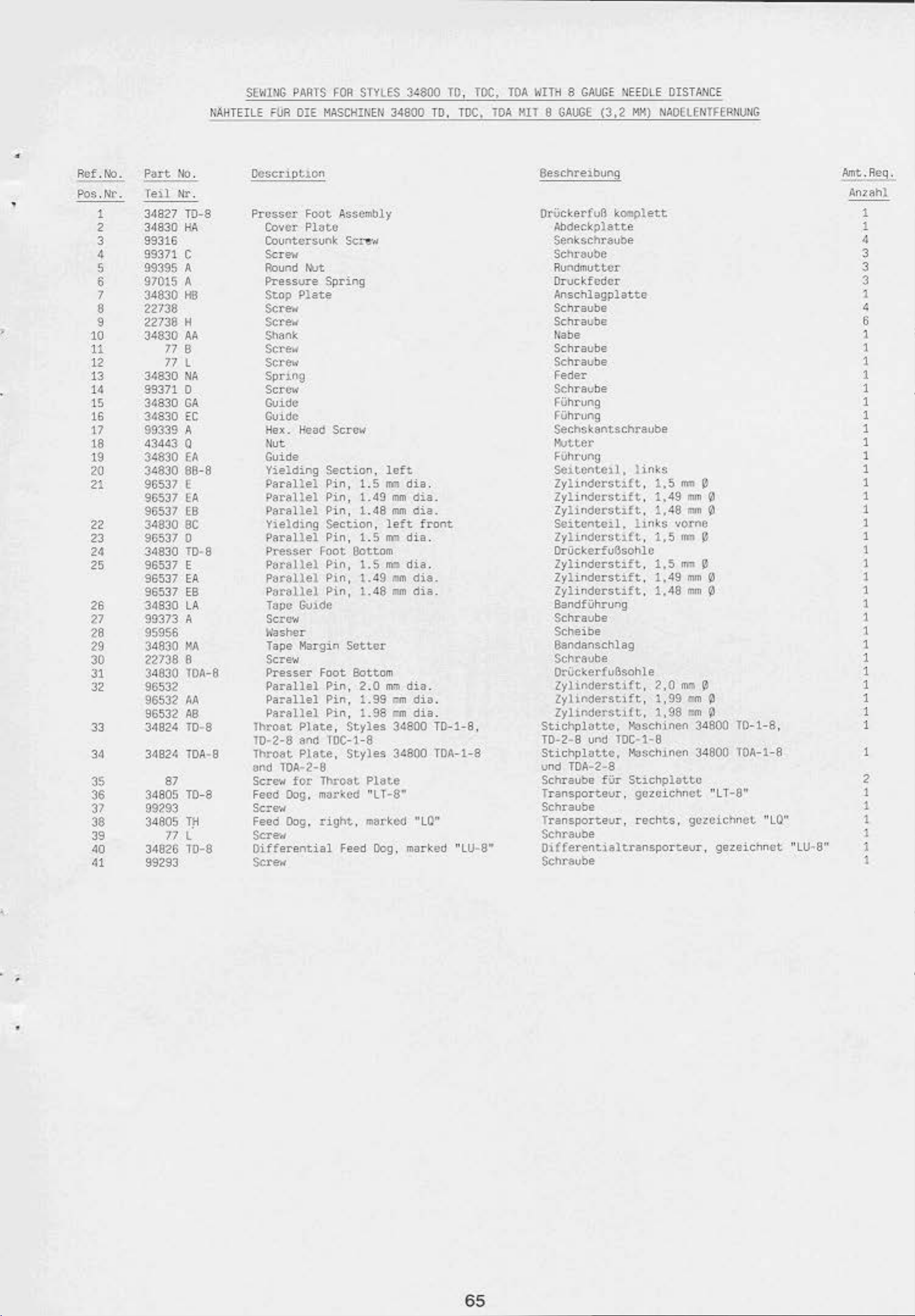
•
•
Ref. t-b.
P~rt
Po$.Nr. Teil
1
2
3
4
5
6
7
8
9
10
11
3<1827
3•1830
99316
99371 c
99395 A
97015 A
34830
22738
22738
34830
12
13
14
15
16
17
18
19
20
21
22
23
24
25
26
27
28
29
30
31
32
34830 Nit
99371 0
3~830
3GS3o
99339 A
43443 Q
3<830
3<830
96537 (
96537
96537
34830
96537
34830 T0-8
96537
96537
96537
34830
99373 A
95956
34830
22738 8
34830
96532
96532
96532
33
34
34824
3d824 TOA-8
35
36
37
38
39
40
·11
34805 10-8
99293
34805
34826
99293
No.
Nr
776
77 l
87
77L
llAHTEILE ftJR
.
T0-8
HA
ttB
H
••
GA.
e:c
EA
88-8
EA
EB
BC
0
E
EA
EB
LA
MA
TOA-8
..
AB
ro
..
e
Tli
T0-0
SEW!IlG
Pros$Cl'
PARTS
DIE
MASCHINEN
Foot
Covcx·
Countcn;unlo;
Ploto
~OR
Assembly
Scr""
P.ound
Pressure
Stop
MJt
Spring
Plate
So-
Screw
Shank
Scr-ew
sc:.:e~o·
Sprl.ng
Scro~o,•
Guide
Guide
Hex. Head
flue
Guide
Yielding
Parallel
Parallel
Parallel
Yielding
Para
Uel
P'l'"esser Fnot Oottom
Parallel
Parallel
Parallel
T"pe Gv1de
SCi"O'N
h'asher
Tape Margin
Scre•,.o
Presser
Parallel
Parallel
Parallel
Th~oat
10-2-0
Thro&t
and
lOA-2-8
Scr~..,
for
Feud Dog, rn;)t·
Sere..,
Feud
Oog,
Sere-<~
Oifferential
Screw
Sera"'
Seceion,
Pin,
Pin,
Pin,
Section,
Pin,
Pin,
Pin,
Pin,
Foot
Pin,
Pin,
Pin,
Plate,
ano
roc-1-8
Plate,
Throat
J.:Cd "Ll-8"
right, m&rk:<XI
Feed
STYLES
Set-e-.,
1.5
1.49
1.48
1.
S
i.S
1.49
1.48
Setter
Bottom
2 .0
1.99
1.
98
Styles
Styles
Plate
Dog
3<800
34800 TO,
left
roo
dia
.
mm
dia.
mm
dia.
left
front
an
dia
.
m,
dia
.
om
dis.
om
dia.
mm
dia
.
em
diu
em
dia
34800
3G800
"LO"
, marked "
TO,
TOC.
.
.
T0-1-8
TOA-1-8
LU
TOC,
TOA
lOA. HilT 9
,
•8 ..
WTT!i 8 GAUGE
GAUGE
»EEOLE
<3-.2
MH)
Seschreibun!=J
OrVckerfvB
~l:ldeckplatte
Senksch~ube
komplett
Scht&u::>e
Ru
l"'dm
uttcr
Onsckf
edc
r
AAschlagplatte
Schraube
Schraube
Nabe
Schraube
Schraube
Feder
S<:hraube
FVhrung
FVhrung
Sechskantschreube
!Wtter
Fi.Jhrung
se~~cnte~l.
Zylindcrst~ft
Zylindcrst~ft
Zylindcrst~ft
Seitente~l.
Zylindcrst~ft
l
inks
.
.
.
li
.
1lk.$
Orlickerfu6sohlc
Zylindorstift
Zylindorstift
Zylinderstift
.
.
.
BandfUhrung
Schraube
Scheibe
Sandanschlag
Schravhe
OtUckerfuBsohle
Zylil'lderstift,
Zylil'lderstift, 1,99
Zylll'ldCl'Stl{t,
Stichplottc.,
T0-2-8
ur'd
Stichplottc,
und
TOA-2-8
Schraube f
T
ransporte
~$Chinen
TOC-1-8
MaSCh1nen
Ur
Stichpluttu
ur .
gozcichnct
Schraube
Transporteu
r,
rechts. gczcichnet
Schr<=Ju'ne
Oi
(ferentialt.ransport;eu
Schr.auhe
OISTAACE
Nf~OELENTHAIIUIIG
1,5
m~ ~
1,49
mm
0
1,49
mm
0
vornc
1,5
~~m
e.
1.5
m~
0
1.49
mm
0
1.49
mm
0
2.0
~, ~
em~
1,98
~
0
34800
34800
"L T
T0
-1-8,
lOA-1-8
-0"
"LO"
r,
gezeichnet
"LU•
8"
Aint
An?.ah
.Req.
1
1
4
3
3
3
,
4
6
1
1
1
1
1
1
1
1
1
1
1
1
1
1
1
1
1
1
1
1
1
'
1
1
1
1
1
1
1
1
1
2
1
1
1
)
1
i
l
•
•
65
Page 61

1
2
8
37
--f
0
aa
o 0 0 -
., -
0
~
0
0
"-
---
e
0
~
14
13
20
-------
-
15
23
p
_,.,.-·'-
(
I
26
24
2
42
66
Page 62

•
NAHTE!LE
S(VINC
FOR
PARTS
DIE
HASCIHIIEH
F06
SffiES
34800
34800
TO.
TOC,
TO.
TOC.
lOA
KTT
TOA
10
NITH 10
GAU;E
(4,0
CAIJGE
HM)
>J«l
UN!l
12
12
GAI.GE
GAUGE
14EDLE
(4,8
DISTAI<CE
KH)
NADELEHTFER•IUNG
•
Ref.No.
Poa.
tt'r.
•
.
.
2
3
•
5
6
7
8
9
10
11
12
13
14
1$
16
17
18
19
20
21
22
23
2•
2<;
26
27
28
29
30
31
32
33
34
35
36
37
38
39
40
41
42
43
Part
M:>.
Teil
Nr.
34827 TD·10
34830
99316
99371
HA
c
99395 A
97015 A
34830HB
22738
22738 H
34830AA
778
77l
34830
99371 D
34830
34830
99339 A
43443 0
34830
34830
96537 E
96537
96537 E8
348308C
96537 D
34830 TD-10
96537 E
96537
96537
34830
99373 A
HA
GA
EC
EA
09-8
EA
EA
£8
lA
95956
34830
22738 8
34830 TOA-8
96532
96532
96532
34824 TD-10
34824 TOA-10
34824
34824
34805 T0·8
99293
34805
MA
AA
A8
10·12
10A·l2
87
TH
77l
34826 T0-10
99293
Oescript.ion
Presser
Cover
Countersunk Sere--
Screw
Round
Pressure
Stop
Foot. AssOIIIbly
Plat.e
r:ut
Spring
Plate
Screw
Serer,.,
Shonk
Scr
ew
Screw
Spring
Screw
Guide
Goid:e
Hex
. Head Screw
Kvt
Gvio'e
Yielding Section,
Partlllel
Parallel
Parallel
Yicld~ng
Parallel
Presser
Parallel
Parallel
Parallel
Tape
Pin,
Pin,
Pin,
section,
P1n,
Foot
Pin,
P1n,
P1n,
Gu1dC
eou~
Sere-"'
IYasher
Tape Margin Set.t.or
Screw
Press
er
Foot
Bottom
Parallel
Perellel
Parallel
Throat
T0·2-10
Throat
ond
lOA
Tht·oat
TD
-2·
12
Throat
and
TDA-2-12
Screw
Feed
Dog,
$c.--
Feed
Dog.
Pin,
Pin,
Pin,
Plat.e,
Styles
and TOC-1·10
Plate,
-2-
Plate,
•nd
Plate,
for
Styles
10
Styles
TOC-1·12
Stylet
Throet
~rted
nght,
Scre-11
Oifferent1el
Scre-11
Feed
(or
10
loft
1.
5
mm
di~J.
1.49
IT'm
d1~L
1.48
1m1
d1a.
left
front
1.5 ~ dia.
1.5
.m
d~a.
1.49 ~ d1U.
1.48
mm
d1a.
2.0
-.
dia.
1.99
.-dis.
1.98
..
dia.
34800
34800
34800
34800
Plete
•Lt-a•
•rked
Dog,
·ur
marked
and 12 gauge
TD
-1-
10,
TOA-t-10
T0-1-12
,
TOA-1-12
"LU-10"
Beschre
OrUcbrfu8
St1chplatte.
TD-2-10 und
Stichp
unci
Stic
10·2-12
St.1ch
vnd
Sehreube
Trensporteor,
Sc-hroube
Trensportevr,
Schroube
Olfterentialtransporteur,
Schr&v1>e
ibung
l:.omplett
Abdeclc.plattc
Senkschraubc
Sc:hraube
Fb.lndnutt.er
Oruckf
Anschlag
Sc:
Sc
No
hta
h.ta
be
eder
platte
ube
ube
Schreube
SChreube
F-r
Schr•ube
FU!=ng
FUhrung
Sechskantschraub•
tlutter
FUhrung
Soi
tenteil,
Zyli
nderstift,
Zylind
erstift,
Zylinder
Se1tenteil,
Zyl1nderstift,
OtUckerf~le
Zyl1nders
Zyllnderstift,
Zyhnderst
stift,
~ift
ift
link
s
1,5 ~ 0
1,49 ~ 0
1,48 m. 0
links
1,5 ~ 8
,
1,5
1,49
, 1.48
Bundfvtrrvng
Schtavbe
Sc
he1b0
B.andonschlag
Schroube
DrUcl:.erfv6sohle
lylinderstlft,
lylinderst1!t,
Zylinderst1ft,
2,0""
1,99
1,98
KaSChlntn 34800
TOC-1-10
latte,
TOA
-2-10
hplatte,
plat
TOA-2-12
Masch1nen
Maschinen 34800
unci
TOC·1
..
te,
Masch1nen
fUr
Stichphtte
12
gezeichnet
recht.s, geze1cl'w'let •Lo·
fUr
vorne
..
~
Mm
11m
e
M 8
m e
34800
34800
10
und 12 g&vge
0
0
1~1-10,
TOA·l-10
10~1·12.
TOA-1·12
·Lr-a·
gezeichne~
Mlt.Reg.
·t~10•
Anzehl
1
1
4
3
3
3
I
4
G
1
1
1
1
1
1
1
1
1
I
I
I
I
I
I
I
I
1
1
1
1
1
1
1
1
I
I
I
I
1
1
1
I
2
1
1
I
I
1
1
'
•
67
Page 63

~
14
13
6
10
35--i
33
36
41
Page 64

•
FWf.
N:>.
Pos.N!'.
1
2
3
4
5
6
7
8
9
10
11
12
13
14
15
16
17
18
19
20
21
22
23
24
25
26
27
28
29
30
31
32
33
34
35
36
37
38
39
40
41
NAHTEILE
Put
No.
Te11
Hr
•
3482/ T0-16
34830
99316
99371
99395 A
97015 A
34830
22738
22738
34830 M
HA
c
HB
H
778
77L
34830
99371
34830
34830
NA
0
GA
EC
99339A
43443 0
34830
34830
96537
96537
96531
34830
96537
34830 T0-16
96537
96537
96537
34830
99373 A
EA
88~16
E
EA
EB
BC
0
E
fA
EB
LA
9S9G6
34830
22738 8
34830
96532
96532
96532AB
34824
348?4
3480S
99293
34~
34826
99293
87
77
HA
TOA-16
..
T0-16
TOA-16
T0-16
TH
L
10-16
S£lii"G
FOil
PARTS
OIL
MASCHINEN
FOR
Oescr1ptton
Presser
Cover
Foot
Plate
Countersunk
Screw
Aound
Preasvre Spring
StoP
Mit
Plate
ScScr""
Shan~
Screw
Scrow
Spt·u'lg
Scr.,.
GulCSC
Gu10U
Hex.
Hol<l
Screw
....
&.!ide
Yielding
PArallel Pin,
PArftllel Pin, 1.49
Perellel
Vleldlng
Parallel
Puuer
P&rellel Pin.
Parellel
Parallel
Tape
$crow
Washer
Tape
Sertw
Prunr
Parallel
Paralltl
Partllel
Throet
1U·2·l6 and
lhroat
and
lOA·2-16
Scre-w
Feed
OOg,
ScrN
Feed Dog.
Screw
Oifferentlel
Screw
Sect~.on,
Pin, 1.49
Sec~icn
Pin, 1.5
Foot
Pin,
Pin, 1.
Gut.de
~rg1n
Foot
Pin.
P1n.
Pin.
Plate. Styles
TOC-1-16
Plate,
for
Throat
~rked
rtgtrt.
Feed
STYLES
34800
Ass~ly
Screw
left
1.5
em
mm
mm
.
lett
~
Botto~~
1.5
..
: .49 m
48
mm
setter
Bottoa
2.0
~
1.99
..
1.98
,.,..
34800
Styles
34800 roA-l-16
Plate
•LT
1s•
-arked
Oog,
34800
TO,
d18.
dift,
dift.
front
dl4.
dla.
du.
dle.
d1a.
dia.
dta.
TD-1-16
•to•
mnJcod
TO,
TOC,
roc,
"lU-16"
,
lOA
TOA
WllH 16
KIT
16
Orvc~erfu6
GAl.GE
GAUGE
'HOLE
(6,4
MM)
komplett
DISTANCE
NAOELEIITFERNUNG
Abdeck.platte
SGnk.schroube
Schrauba
Rundmutter
Orucl:feder
Anschlegplnte
Schreube
Sehreube
Noll
be
Schraube
Schrevbe
Feder
Schtt'vbe
FVhrvng
Ful'lrvng
Stchs~antsehrJube
...,tter
FUt>rung
Seitenteil,
7ylinderstift,
lylinde
rstift
11nks
1.~
, 1,
mM
49
Zylinderstift, 1,48
Seitenteil,
Zyllnderstift,
links
1,5
vorne
f!"'l
OruckerfuBsohle
Zyltnaerstift,
Zyltnders~if~.
lyhnc:serstift,
1.5 ~ •
1,49
1,48
Bondfvhrung
Sc:hraube
Sc:heibe
Bandanschlag
Sc:hraube
OrUckerfu6sohle
lylinderstift,
Zyl~nderstift,
Lylinderstift,
Sttchplatte,
10·2-16 und
2,0
1,99
1,98
Masch1nen
TOC-1-lG
~
St.1chplatte, Maschinun 34800
unci
TOA-2-16
Schravbe fUr
~ichplotte
Transporteur, gezetcnnot "LT-16"
Sd>roube
Troh$porteuT,
Schnube
recnts,
Dl!fcrcnttaltransporteur.
Schroubc
0
mm
p
tMl P
0
mag
ll"'ll
0
Q
._
e
M8
~
34800
geze~chnet
TD-1-16
TOA-1-16
•tQ•
gczetchnet
,
•tu-ts•
:ne.Req.
Anzahl
1
1
4
3
3
3
1
6
l
1
1
1
1
1
1
1
1
1
1
1
I
1
1
1
1
1
1
1
1
1
1
1
1
!
!
!
l
1
2
1
1
1
1
1
1
'
69
Page 65

--
---
~--
---
--
-
f
fJ"
?
)
6
I
I
1
L
---
-
....
--'
------
28
------
-
7
To
chip
Zur
d.
Abfal~
To
Zur
spos&l
absavgung
chip
Ab( )Ol$POsol
• Lob•
..
riUgung
13
.
__.:.--
1
I
1
I
I
I
1
I
I
I
I
\
I ,......-"
\,._
...........
..
---
..............
...-
_
--
.....
....
I
22
).-
--
----
21
IL.
-
---
___
---
I
••1\
,....
---
........
--
l
'
-~~.,...1
-
'
To
air
two
devtcc 9 motortng
lum
der zweh
Zurnenein .r
c 1-
·sta ! tnder
luftz
1.
Y lncler
~uno
on
l
Chtong
of
70
Page 66

COflrAOL
$1'EUERU
1
~GS
THlf
PARTS
l
lJA
FOR SIYLE.$
OJE
foiASCHHiEN
34800
l0-1
AM)
34800 T0-1
34800 T0-2
~0
34800 10-2
•
•
Ref
.tiO
.
Pan.
Pos.l.r.
1 I 1
t
2
3
II
lf-11
!'Yl6aJ
~q9
~9fill3
90'J61
5 99Wft
£.
1
8
')'lj';
'J'l61~
902)~
9 9~
10
11 990 367
ll
t:J •
31
IJ
14
IS
16
17
18
19
20
9?9 )4ij·0,315
905(;1
99683 "
~
• i"•f.83 t
90'/M K
t)¥,1 248 A
~qq
ft
C)')
~(}ij:J
'1't'f·
'1%1~
~liS
9()')(,1
'J~
'"'"'
·
lor.
"
179
c
K
H~
155
1
4l'6
G·
1000
DAD
~·~-0.63
KA
II
111J
2•9
149
H·l
55
126
G
1SOO
~~
l?h
c 2991:?
!10?35
1)()!,&1 H
OAO
998
J4ij·0,6.1
'l'lB-348
~"J'JA
387
0,315
M/.1
Dcscr-tpi.Jon
r~trol
flltcr
F
U
Anund
lt6eOle
(c()l!ltJ()nt:-nts
Str
P£ I ubi G.
Control
fU~I•
Purts
~~vl&tor
tl
t.t.tr-
Rt:gt~lator
oloor
Heod
Rod
• 1
qf'lt
Corw"tector
d,
eo.
Fu-.o
BruJ.fjP.
Roun(l tleaa ltbod
Con~rol
F1l~r
fllter
ttolcJu-
Aound
1-Poknt
?-Polnt
Plug
Parts
Regulator Assembly
AegulaUir
Hcod
OutlC~
Ol~~rtbvtor
Gasket.
lrcoCilc
fbd
(compont:nt.to
Stratght
Pf_
I~
f lo••
fbJnd
Strutqnt
Kn(1f: Valve
Sl'l~
Con~rol
fu·.tl
fu<:.4•
Brtdgol!
Round
~~tor
6•1.
Control
Head
Connector
ll.ltj
E!
(lox
HP.ad
'bXJ
Asso-:1
73)
Plug
for
wood
Valve
sec
page
length
for
ht)Od
Rtng
V;Hve
:..ee
paqe
length
Valve
Screw
bly
hbod
s~rl•
34800
Assembly
Screw
~sr.embly
73}
1
litter
Scrow
Stylo
Screw
34900 T0-2
Ptpo
lic;!.embly
73)
1,
5 II!Ct.c:r
(components
Sere-
...
10-l
Bc:.chretbun
Steverungstetle
flltcrdruckmtnderer
f1ltc
g
raruckm
fur
tnderor
Kasehlne 34800 TD·l
komplett
Halter
HolbrundhOllschroubo
7ugstongeoven
(Etnze
Gerade VerschrauDung
P(·Aoh:
Schalt
lte
kasten
$1ch
erur.g
erung
S1ch
BrUck
enstec"-cr
ltll 1 brondholl:> C
Steuerun
J.t I terdruck111.tn61·
ftlterdruct•lnek~re~
ti
J.le
slehe
6xl,
1
gstetlc
1 komplett
Seite
Xoter
lang
hrovbtt
fur
Meschine 34800 1
rer
ko~let.t
73)
Halter
Htlbr~nolzschreuce
Vort..etlerring
Vl.wtotlerrohr
1-foeh
2-fueh
Oicht.nng
7.u~~ta~enventil
(Etn~elteile
Goreoe \1e.rschraL.Jbung
PE-Rohr
6•1.
Orol;sctventi
Ktlb~lzscnraube
Cor~de
Kntevcnt.1l
tieh
Schal
Verschraubung
o SC.tte
tkasten
Si
chcrung
Stche
rung
koeplett
BrUd:en.st.ecl:
Halbrundholz~chr•vbe
sicho
1,5
1
73)
er
komplct.t
Sott.e
Mot.er
lang
(E1nzelteile
13)
0-2
limt.Req.
Ant&hl
1
1
1
2
1
1
I
I
I
1
1
•
1
1
I
2
2
I
•
I
2
l
1
2
2
1
1
1
I
1
4
'
•
NOTE:
lhf·
Iii
t.vbcs huvc
I4·HcJth\. t.o
~t.tc
ht
part-s.
to
oo
be:t..ween
cut.
t.u
t.ht'
p.ort.J.eular
teQU'il"ed
BEACHltrC
l.engen
dte
SIE: Die PE· Rohre mUssen
geschnttt.en werde:"''. d$111t
einzelnen
Pneuaeti
kteile pessen.
euf
dlft
bcnot1gt.en
$11
zw
uchen
71
Page 67

\
~·
6)
0
c
•
Fig.6
9
Page 68

1
3-i
19
16
7
7
To
chip dispos
Zur
Abfallabseugun
I
I
I
I
I
1
I
I .,...-'"
-
--
--
--
--
8
13
al
g
\....---
:
L
,--
21
/-'"\_
To
Feat Action
Zum
Abachntidtr
- ~
Tape
---
Outttr
Schnelle Sch
ere
38
24
23
22
~
72
Page 69

•
P.et
.No.
Pos.Nr.
1 • 19 19916
1 99683M
2 999-179
3 99683 c
4
5 999 248
6 999 249
7 999 149
8 99683
P•rt
•.o.
Te11
t.r.
lCD
90~61
K
H·
155
9 999-175
10
11
90~61
s
999·145
:2 999-126
13 1297002
:4
15 90235 080
16 998-3.48-0, S3
17
18
19
20 99675 G
998·338 A
998·348-0,315
998·387
a6:
H
100U
CONTROL
STEUEAU'.CSTEllE
Control
34800
Filter
1-Point
2-Point
Gasl::et
~low
Round
Straight
Str&lght Connector
PE-Tvbe
Control
~A
PE·Tune
.PARfS
FUR
Parts
TOC·l
qcgulator
Filter
holder
Rourd
lreadle
(components
(ole&$e
(nee
Fuse
Fuse
an.dge
Round
Regulator
Head
OJtlet
Oistributot•
lbd Valve
Control Valve
Head
Connector
8x1,
specify
Sw1tch
SOx
Plug
Head
6x:,
t"OA
STYlf
DIE
P<ASCHI•1
k.:~,t
for
AiSI50ly
Wood
Ser~-,.,
Ring
Asst.'lllbly
see
beloH)
';fOod
Screw
length
length
Ass.eltbly
\!bod
Ser.,..,
length
1
34800
Style
P.1pc
1,5
..
"'hen
muter
TDC·l,
3<800
TDC·1,
ter
oroonng)
TREADLE
ROD
Zt.CSTA.'lGEWENTll,
Stevcrungste1lesetz
34800
FJ.lterdrvcl<mlnd(:.ret
Filtcrdruckmtnde~~
~alter
Halbrundholzschr3ube
Verteiler=ing
Verteilerrohr
Olchtring
7ugstangenventil
(Einzelteile
Ol'OSSelventil
Halbrundnolzschraube
Gerade
Gerade
P£-Roh~
(bei•
lCnlesc:hal
SehalU.&Steo
S.1cherong
S.lcnt:nJt'lif
8rvdtensteet.er
HalbrundhOltsehrw:oe
PE-Rohr
VALV€,
KllH.
VALVf
KI<IEVENI!L
fUr
TOC·l
1-fach
2-foch
komplctt
siehe
verschrau~ung
verscnrau~ung
Sxl.
l,S
8estellen
ter
~~:oeplett
6x1.
1
Heter
unten)
Meter
bitte
lang
Masch1ne
k~lett
lang
lilnge
onge-bcm)
__
...,_
An.z.ahl
1
1
1
1
2
2
1
•
I
1
2
I
I
1
I
1
1
1
I
4
1
21
22 999-146
23
24
25 99683 J
26 99683 K
27 95173
28 110-4
29
29A
:M 999-140
31
32
33
J,4
35
36
37 99675 •
38
39
-10
41
42
-
13
44
45
46
47
48
49
50
51
99683
95250
95250
99683
9!>151
99~
G
28562
~I
G 2991?
95954
99688 u
99~87
99689
99689 A
90561 0
99675 G-1000
G 21233 D-4
90561 c
H-1~5
999-145
999·126
999-139
E
A-155
A
999-129
906
B
0
999·127
999 126
Treadle
lin~
Rod
!Wt
Nut
Stud
Guide
Screw
Spring
Straight
(1-for
Style
3<800
Str3ight
(1-!or
Style
3<800
'tJffler
312
H&y
Cotw'lect.lon
Screw
Rod
Cla.o
tor
Scr.-.
PE-Tube Bx!.
Kr.es
V~lve
Valve
ScrC'H
\''asher
Clamp
Knee
Actuator
SwJ.vel
Straight
1-blder
Clamp
Round
Head
PE-Tube
Tube
Cl~
Round
Heed
Valve A!'lsembly
Connector
Style
34800 T0-1, 2
TOC-1)
Connector
Style
34800 T0-1,
T0-2)
ca.
Valve
99683 f
length 1 mettr
Ass~oly
ElbOio.'
Connec~r
Rod
U:~od
ScreH"
Sxl,
length
'lt)od
Sere-...-
for
P€-lube
Jor
for
PE-Tubo
2-for
1
~t:~t.er
8x1
6xl
lugstangenventil
Wlnkelgelenk
komplett
Mutter
Mutter
Bohen
Fuhtvllgs.s.tV.cJ:
Schnwbc
Feder
Gerade
(1-fUr
Mascnine 34800
Gerade
(1-fUr
VerschrautM
~schine
..
mg
3~800
TDC
Verschraubung
Maschine
34800
(Ur
10-1,
1)
tur
TD-1,
Kaschine 34800 T0·2)
Schalldampfer
312
Nege·'bckerwentil
Yerbi.ndwngsstilcJ:
SChr31.10e
fUr
99683 E
SU>n$e
Q~t.Uclc
Schr-eube
PE-Rohr
Kn1eventil komplect
'lent
Schr-.aube
Scheibe
Kle=rostUck
Knietaster
Wlnkel-$chwenkverschroubung
Gcrade
H-.lt.cstange
Klc~~mstVck
ka
lbruncfho
Pf-Rohr
Rolu"sche
kalb~lzschtaube
8x1,
it
Verschraubung
12
s.chr<:~ube
6xl. 1 Meter
llc
l Met.er
lang
lang
PE·Aohr
8xl
2·fUr
Pl...F~hr
6x1
2·fur
1
or/odor
1
2
1
3
I
1
2
1
2
2
1
I
I
2
2
1
1
1
1
1
2
2
1
1
1
1
I
1
I
2
2
2
NOTE:
T~
Pf:-t.ubes have w
le-ngths
pnCU~~.otlc
to
parts.
flt
be
between
cut
to
reQuired
the
i);f!l~iculer
73
SUCHTfN SIE:
Oie
PE
t.angen c:;esct-:-tiu:.en ·.·eroen,
die
einzelnen
Pr~umattkteJ.le
Rohre
.ussen
14.1(
c11e
dMl t si.e
p•saen.
ben0t1.9ten
z:wuehen
Page 70

'
,.__-
_ ... A
..
15
16
~
-
18
~
I
; 20
~
,,
~
~
\·)
17
'
.
I
19
21
~
~[
22 25
~
~
;e
p •
"
~
I{
~
I*
1
z~
74
t
J
.)
!
Page 71

•
Rot.No.
Pos.Nr.
1 21102 6
2 93064 H-1
3
4 G 21217 A
5
6
7
8 21104 c
Part
Tell
201C
188
22728
93064
9 95510
10 21104
11
12
13 22651
14
15 34375
1G
17
18 51295 8
19
20
21
22
23
24
25
26-
27 90710 G
21114
600-738
90561 K
22757 E
34395
421 C-
421 E
118 G
21202
95007
c 21201
28004 u
999-114
999-114
No
Nr,
0
EA
8-18
AU
C0-4
.
34
8
c
Oesctll)t\On
Tape
Rool
Rod
Cone
lhu!tlb
Rod
Thui!C)
Thumb
L-llod
Aod
Set
Rod
a
...
Ceplug Cover
Screw
Suppor-t.
Screw
Screw
Connoetton
Serev
Set Scrw
Wood
scr.-..
Belt
Gvard
Counterevnk
Rubber
Rubber l&Olfttor
lifter
,.,
..
Tweezers
Screw
W!'eneh
Screw
Hinerel
Dr1vor
Or1ver
(17 ounces)
Superfast
content•
Engi-nHTing
ovst
Cover
Hoad
Proflle
Chein
011,
c.n
Eng1neer1ng
10 ml
AdhC$lvC,
(not
Scrt'"
content.s
Adhesive.
contents
~hown)
ACCESSORIES
ZUIEHOA
0,5
hters
10
a1
Su;;chrel.bu~
ktt.R!_9.
Anz:ahl
8androllcn~Stange
Kogel 2
RandolSchraube I
KreuzstiJck
Rindelschraube I
Rindelschraube
WJnkelstangc 1
S~n-Verbindong
Gew1ndesti
Sto<>ge
fuB 1
Ab<SeckJcappe
Gew1ndestift
Holzschravbe 3
R1emenschu
S<,nkschraube
ProJ:Hgu~m~i
Gum'rllPvffer
L1ftcl'k.Ctte
Hok.cn
ft.
tz
Pullett.e
Sehraubendrcher I
Sechstan~-StiftsohlV$Sel
Schraubendreher
MtneralOl.
Superschnell-Konstrvktlon~kltber,
Inhalt
Konstruk~ionskleber
Abdeckhaube
10
0.5
al
L~ter
(nicht
Kentster
,
Inhelt
abgeb1l~tt)
10 ml 1
1
I
1
1
2
1
1
1
1
4
1
5
I
2
I
1
!
2
1
1
'
•
Not
furnished
purchased
w1th
machinH,
scpe~tely.
1\as t.o
be
Wi-r'd
gegen
nicht
:::r1t
zusattll.Che
den
Maschinen
8estellung.
gehcfert,
erhilt.lich
75
Page 72

..
.
::.:r
~
m
--~
·O:..~
'·' : ..
..
.
•
e
......
/'"
·-~·
:;;
y.>
. .
..........
...,.
$ -
..
--
....
..
~
1,(...-
:.)?"':\
.
.,.,_
' .
76
Page 73

THilEAD
FAOENST~~
S I
AHOS
•
•
~(.,.,,
Po&
.Nr.
Part
Nl. Oeser
Teil
Nr.
21101
21101
....
W-5
ipt1on
Threod
t.wo
T
hre
Swnd
-noadlo mochines
ad
St.tnd
three-notdlo
Assembly
As.SCtllbl
m~Chines
y
for
for
8eschre1bung
Fadenstander komplett
lweinadelmaschlnon
~adenst8nd
er
kompl
ctt
Oreinedelmaschinen
~t.
Anzehl
fiir
fVt 1
.Req
.
1
•
,
•
77
Page 74

AUF
WELCHER
NUMERICAL
SEITE
FINDE
I~IDEX
ICH
TEILE
OF
PARTS
UNO
IHAE
A88ILDUNGEN
Part
No.
Teil
N
r.
18
............. 37.
20
............. 45. 47.
..
Cl
HS
co
co
co
20
B .........
21
. . . . . . . . . . . . .
25
s
.......
24
c ...........
27-435
28
28
28
30-106
50-434
G
G 50-726 .
G 50-800
G 50·802
52
67
67
67
73
73
75.
77
77 8
71
77 K
77
77
77
79
J
87
87
J
87
89
88 8 . . . . . . . . . . .
88
89
90
92 . . . . . . . . . . . . . 37
93
95
97
98
98
109
110-4
118
187
188
201
376 . . . . . . . . . . . . .
402
421
421
531
604
60S
660·207
660-210
660-212
660-219 p
660-308 . . . .
660-4
660-738 . . . . .. . . .
666-149 . . . . . . . . . 39, 43, 45,
666-199 . . . . . . . . .
666-214
906 8 . . . . . . . . . . .
997·YY-4S1
998-59 . . . . . . . . . .
998-246 A . . . . . . .
998·338 A . .
998-348-0,315 ... 71,
8LX
.............
8
...........
c ........... 53.
8LK
. . . . .. .. .
........
.........
.........
A
.....
8 ........... 4
0 ........... 41
E
...........
A
.......
c
....
...........
.............
..........
F
.........
.........
l
........
p
. . . ' . ' . . . ' .
0 . . . . . . . . . . .
J ...........
. . . . . . . . . . . . .
u .
..........
J . .. .. . . .. .. 47.
. . . . . . . . . . . . .
D . . . . . . . . . . . 35 999-211 8 . ......
. . . . . . . . . . . . .
. . . . . . . . . . . . .
. . . . . . . . . . . . .
.........
A . . . . . ' . . . . .
............. 43,
A
.
..
..
......... , .
.......
G . .. .. . . . . ..
.........
•
0 . . . . . . . . . . .
c . . . . . . . . . ..
. . . . . . . . . . . . .
C-34 . . . . . . . .
E . . . . . . . . . . .
. . .. . . . . . . . . .
.. . . . . . . . . . ..
A
.. .. . . . . . . .
.. ..
.........
..
59
. . . . .. .. .
. . . . . . . . .
..
....
.....
. . . . .
......
.,
....
.......
.
..
..
...
41
37
.... 31,
. . .. ..
..
.... 13 999·214
.. 53.
53,
51
49
75
<9
35
47
.
.
.
49
51
35,
45
49
;s,
75
53.
35
73
53,
53,
57
'
73
... ..
......
......
.. ..
. . . . . .
.. ..
Page
Sci
tv
45
61
41
45
45, 53, 55,
57,
59
37
47
39.
45
47
57
41,
43
33
53,
57
53,
57
53,
57
1,
43
4
1,
43
47
57
53.
39
45.
63
;s,
59, 65,
67,
69
37,
51
43
51, 65, 67,
63 99963
37
37,
65. 67.
37
51
51
51
41, 43, 45,
45
•5
53.
47
49
15
57
57,
75
75
37.
59
57
57
51
73
57
75
39
69
69
51
51
•
,.,,
Pan:
Te11
r<r.
998-348-0.63 . ... 71,
998-358 F . ......
998-364
998-387 l
998-387
998-426 8
998+426
999-4
999-4
999-59 B .
999-59 p
999-78 . .. .
999999-109
999-114
999-114
999-126 . . . . . . . . .
999-127 .. .......
999-129
999-139 . .
999-140
999-144
999-145
999-146
999-149
999-153
999-166 . ........ 35
999
999-17~
999-179
999-192 8 .......
999-1
999·199 A .
999-205
999-211 . . . . . . .. . 33 G
999-211 A .
999-211
999-211
999
999-211
999-212-035
999999999-213 8
999-213 R
999-214
999-215 .. .. . .
999-215 A ..
999-216
999-232 .
999-248
999-248
999-249 . ........
999999-313 A
999-313 8
999-313 c
999-313 s ..
1096 . . .. .. .. .. .. .
2161
2165
8312
9937
10142
12865 .
12934
15430
21101
21101
21102
2110
4
21104
.
.....
s
. ......
..
.
.....
. . . . . . .
B.A.
. .....
A . ........ 43
8 .
.......
..
.....
. . . . .
..
....
93
. .. ' ......
. ......
8
. ......
B
. ......
c
.........
.. .. ..
. ..
..
.... 61.
A .
.....
.
......
.
........
.
...
.....
.......
•
- 171
175
c
K . ......
..
..
96
..
.
......
.......
......
.......
......
H
.
......
...
...
c .
...
...
D .
......
-211
E .
......
G .
......
212
-062 ..
212-520
..
..
...
.......
. . . . . . .
SA
. .....
WA
.
.....
..
.....
.
...
.....
...
.....
. ........
A
. ......
25<
. . . . . . .
J
.......
.......
.......
..
...
. .
........
0-0
,5 ..
A . .
....
. .. .
........
.
...
.........
...
......
. . . . . . . . . . .
•
l . . . . . . . . . . .
w-4
. . . . . . . . .
w-5
. . . . . . . . .
8 . . . . . . . . . . .
8·18
c . . . .
..
......
..
...
.....
.....
...
. . . . .
P•a•
~
73
59
.
.
53
61
71,
53.
53.
43
63
57
.
73
57
57
. 45
. .
33
61
39
75
33
.
75
71
,
73
73
73
.
13
73
45,
.
..
.
. 33.
.
. 31,
63
73
73
71,
61.
59
63
61
71
,
71
,
59
35
61
61
33
35
33
43 22585 c ...........
33.
35
47
33
39
39
43
43
43
45
33.
45
73
71
71 • 73
35
45
45
39
39
39
53
.
47
61
49
51
47
45
77
77
75
75
75
73
73
43
35
53,
~~
41
73
51
Part No.
1e1l Nr.
21114
G
21201
21202
21217
G
G
21233
21657
21657
21657
G
21657
G
21657
22503
22513
22513
22524
22528
22537
22539
22541
22542
22548
22557
G
22559
22560
22561
22562
22562
22562
22$64
22564
2256
4
22565
225
69
2
2510
225
80
22581
22582
22585
22585
22585
22585
22586
22593
22596
22598
22651
22711
22726
22728
22729
22729
22729
22730
22733
22738
22738
22738
22743
22757
22766
22768
22795
22797
22798
22801
22805
22811
22829
22839
22839
22840
22848
22874
22874
22814
AU
. ........ '
..
...........
. ............
A .
..........
D-4
. ........
y
...........
AA-4
M-5
X . . . . . . . . . . .
WA
. . . . . . . . . .
F . . . . . . . . . ' .
. . . . . . . . . . . ' .
. . . . . . . ' . ' .
8
.
............
.
............
.
............
.......
B .
..........
. . . . . . . . . . . . .
. ..
........
.
..........
G
A .
..........
.
..........
8
.
..........
..
..........
A .
........
.
.......
8
. . . . . . . . . . . . . 37,
. . . . . . . . . . .
8
. . . . . . . . . . .
0
..
.........
c
8 . .
.........
. ............
0 .
..........
.............
.............
.............
...........
•
8 ...........
A . .. . . . . . . . .
A .........
. ......
. ...
......
..
.........
c
C0-4
.............
.........
..
...........
A
...........
0
...........
E ...........
....... . ....
E ...........
.
. -.
8 .
........
H ........... 65, 67.
.
........
.
......
e
... ..........
.............
.............
.....
.............
.............
.............
8 .
..........
.............
c . .......... 33
E ...........
c
...........
.............
. . . . . . . . . . . . . 33
. ........
c
F
...........
. .......
. .......
....
..
..
..
. 53,
..
...
..
..
' .
..
... 49
.. .
..
...
...
.
........
..
....
.. .. 37.
"
......
..
Page
Seite
75
75
75
75
73
49
49
49
33
49
41
37
, 43,
35.
37
35. 51
49
33
37, 41
45
37
49
39
43
47
39,
45
35
.
47
35. 51. 53. 57
33.
45
43
55,
39
35,
41,
35
43,
37 . 51
39
41,
49
39, 75
37
37. 61
15
63
51
51
31
33
65,
41,
43
37
39, 47 •
45
51
35
37.
;s,
41
33
63
49
47
41
51
61
49
57
47
<1,
49
49
43
59
41
41. 53,
45
43
67
69
65, 67.
69
7>
51
61
59
57
69
78
Page 75

AUF
WElCHER
NUMERICAL
SEITE FHlDE
INDEX
ICH
OF
TEILE
PARTS
lHRE
UNO
ASBilOUNGEH
"
•
Par't
No.
TOll
Nr.
22883
22892
22894
22894
22894
22894
22894
22894
22894
22894
22894
22894
G
234~1
c
28~62
28604
c 29066 0
c
29tOS
29327
DZ
DZ
29328 .............
G
293<8
G
29416
c
29476
c
29476
CA
29477
c
29912
29916
29916
29916
29924
29933
29986
29966
33174
33703
33744
33795
34304
34304
34306 .............
34306 0 .
3431~
34316
34316 8 ...........
34317
34321
34321
34323
34325
3432~
34329
34334
34335
34335
34335
34335
:
34335
34335
•. 34335
3<335
'
34335
34335 J ...........
34336
3~336
34336 B ........... 33
34336 c . . . . . . . . . . .
34336
34336 E . . . . . . . . . . .
34336 F . . . . . . . . . . .
34336 G . . . . . . . . . . .
34336
34336
34336 0 . ..
34336
34336 T
~
Seite
........... 35,
•
E ...........
c
...........
E
...........
F
' • 0
••
' • • • • •
R
. . ' . . . . . . . .
T
. . . ' . . . . . . .
' . " .
......
X . . . . . . . . . . '
"
AO
. . . . . . . ' . '
Al
..........
AY
. . . . . . . . . .
A ...........
A
.........
u ...........
...........
F
...........
.............
0
..
• 0
••••••
as
. ........
au
. . . . . . . . . .
av
. ........
AP
. . . . . . .
..
..
49
39,
33,
45
43
35
47
37'
53,
33, 35,
43
37
53,
73
15
39
39
33
33
39
43
39
41
41
.
............. 71,
AA
.
..
. . ..
..
.
33
AAC
.. .. ..
reo
.........
A
.......
BA
. ' . ' . ' . ' . '
AN
..........
ANP
.. '
0 . . ' . . . . . . . .
IC
. ' .
c ' ... '
c • • • • • • • 0 • • •
.........
c . . . . . . . . . . .
..
.............
. . . . . . .. . . .
•
.............
A
. . . . . . . . . . .
CA
. . . . . . . . . .
........
H
........
v
........
CA
.....
s
.....
.............
A
..........
...........
0
c .........
Q
.
..
e . . . . . . . . . . .
F ........... 33,
G
...........
H
. . . . . . .
. . . . . . . . . . . . .
. . . . . . . . . . .
•
Q
. . . . . . . . . . .
,,
. . .
p
.
.. ..
...........
s
...........
......
...
.....
. . . .
.....
.....
0
....
..
... .
..
. . .. ..
. .
..
. .
..
.
30
73
...
.
51
61
53
57
45
. .
..
55.
. 53.
47
0
..
..
..
.. ..
47
...
47
39
. . 43 34358 D
39
39
39
38
38
39
43
43
...
43
...
35
41
.
43
43
.
43
43
..
..
43
43
41
43
. .
41
41
41
33
33
33
33
33
41
43
..
41
41
43
47
43, 45
41'
39
39, 41.
57
43
57
73
59
57
43
Part
...
....
Te11
34336
34336
34336
34336
34336
34337
34337
34337 8 . ........ ' .
34337
34337 0 ........ " .
34337 [
34337 F . ..........
34338
3433-B
34340
34342
3042
34342
34342
3~342
34343
34343 c
34343
34343
34344
34344
34344 c
34344
34344
34345 .............
3-1347 X
34348
34
34
34353
34353
34354
343S~
34356
34357
34358 E .
34358
34358
34363 A . ..........
34363
34363
34364
34364
34364
34366
34367
34367
34
34
34
34
34382
34382
34382 H
34382
34382
34382
34382
34382
34382HA . .........
34383 . ............
34383 • . ..........
34383
34383
34383
34383
34388
34390
34390 A
u . ' . '
HA
LA
•A
AA
.......
. .........
. .........
. .........
' .........
.............
A
. . . . . . . . . . .
c . . . . . . . . ' ' .
•••••
0
.....
..
' ..
......
8
..
......
.
....
........
A .
..
.... ....
8 . . . . . . . . . . .
. . . . . . . . . . .
c
0 . . . . . . . . . . .
E .
..........
8 .
..........
.
..........
l
...........
AA
. .........
.............
A .
..........
. . . . . . . . . . .
0 . . . . . . . . . . .
E
..
.........
..
..
.. .. ..
"
..........
350
.. ...........
350
...........
0
.. ...........
A
...........
..
..........
.
..........
•
........
KA
..
0
. .........
.........
..........
SA
• 0
••••••••
CA
.
.........
c . ..........
E
..........
A .
..........
.
..........
c
SA
.
.........
..
...........
..
...........
A . . . . . . . . . . .
367
368
315
382
...
.......
6
.............
............. 37.
0 ... ........
F . ..........
G . ..........
••• 0 ..
v .
CA
LA
...
UA
. ..........
c
c . ..........
SA
88
. . .
..........
• 0 • •
•••••
•• 0 •••••••
. . . . . . . . . .
. . . . . . . . . .
. . . . . . . .
. .
..
..
.............
. . . . . . . . . . . . .
. . . . . . . . . . .
..
.. . 41
.
.
'
....
.
.
..
•
..
..
..
~
Seite
41
43
43
43
41
43
43
43
43
43
43
41
41
41
33
33
39
39
41
39
41
41
41
41
41
41
41
41
39
39
41
39
39
41
41
33
33
49
49
37
37
47
47
47
47
35
37
37
37
43
37
37
37
43
35
35
35
41
37
37
37
35
37
37
49
33
49
49
49
49
53,
33
33
,,
57
Pan: .
...
Te1.l
hr.
343900
34390 H . ..........
34390
34390
34390
34393
34
393
34393
34393
34393
34393
34393 f
34393
34393 H
34393
34393
J.ol393
34393
34393 s ...........
34393 T •
34394
34394
34394
34394
34394
34394
3439~
34?01
3~701
34702
34704
34709
34722
34725
34725 A
3473-4
34734
34734
34734
34736
34736 K . . . . . . . . . . .
34736 N . ..........
34736 p
34738 . . . . . . . . . . . . .
34738 • . ..........
34739
34739
34749
34750
34750
34757
v 34757
34758
34763
34763
34763
341
347
34763
34763
34763
34763
34763
34764
34770AH . .........
~771
34771
34771 B
34771
34771
34771
34771
34771
34771
34771
. ..........
ex
. .........
ex
' • ' • ' I ' ' ' '
CA
'"''""'
. ....... ' ....
A
' ... " .....
. ..... ' ....
8
. ..........
c
. ..........
0
(
...........
..
.........
. ..........
L
.
..........
u
..
.........
p
..
.........
0 . ..........
A ...........
••••••
.. . . . . . . ....
A ..
.........
c .
..........
E .
..........
F . .
.........
c .
..........
. . . . . . . . . . . . .
..
.........
6
6A
. .........
..
. ' .........
..
"
....
' . . . ' . . . . . . . '
..
........
..
...........
..
.........
' . . . . . . . . . . . .
H .
.........
J .
..........
K .
..........
L . . . . . . . . . . .
. ..........
.
..........
•
.
..........
8
AH
. .........
A . ..........
c . ..........
.
............
. ............
.............
8 . ..........
c • ' • • • • 0 • • • •
F . .. " ......
63
G ... '
63 H
J .
K
L ...........
H . ..........
SA
c
.......
...........
..........
' ' o ' ' ' ' I o ' o
•
•••••
•••••••
.............
...........
•
...........
c ...........
...........
D
E
...........
F . . . . . . . . . . .
G
..
.........
H .. ........ '
J ...... .....
.....
~
Seite
33
33
33
33
33
35
35
35
35
35
35
35
35
35
35
35
33
33
33
0
...
33
35
35
35
35
35
35
75
37, 61
37
37
47
41
43
39,
"'
43
43
43
.
45
45
45
•5
45
•5
•5
41
51
51
51
51
51
51
.,
47
47
51
51
43, 47
47
47
47
47
33
33
0
•••
51
0
•••
37'
51
51
51
51
51
51
51
51
51
51
51
61
79
Page 76

HUHERICAL
AUF
WELCHER
Port
.
...
T
ell
tlr
.
34771
34771
34771
34776 L .......
34776
34777 0 ........
34111
34118 G
34118
34118
34779
34782
34782
34782
34782
34782
34782
3d785
34794
34801
34805
34805
34805
34818·8
34818-10
34818·12
34818-16 ..........
34818 A ......
34818
3•824
34824
34824
34824 10-1
34824
34824
34824
34824
34826 ro-a ........
34826
34826
34827
34827
34827
34830
34830
34830 88-16
34830
34830
34830
34830
34830
34630
34630
34630
34630
34830
34830
34830
34830
34830
34
831
3
4644
3
4844
34845 A ..
34846 A
34847
34847
34848
348480
34852 . . . . . . . . . . . . . <5 52778 X . .
34852 •
34852 8
34852 c ...........
34852 0 . . . . . . .
34852
. . . . . . . . . . .
K
.....
L
AA
...
..........
....
CA
........
OA
......
.......
......
G8
.......
GC
..........
A
A
.........
...........
c
...........
0
. . . . . . . . . . .
F
.. ..
u
TA
.......... 37 348
....
....
....
....... 37
.............
..........
...
.......
.....
TOo8
.....
......
....
TOotS
TH
...........
..........
.
...
......
...
. . . . . . . . . . .
8
...
TD-8
TD-10
T0-12
lOA-8
TOA-10
TOA-12
TOA-16
Tl)-10
Tl)-16
ro-a . . . . . . . .
Tll-10
Tl)-16
AA
BB-8
llC
EA
ec
GA
HA
H8
LA
..
NA
ro-8
Tl)-10
T0-16
TOA-8
TDA
c
..
..
..........
A
.. ..
.....
....
....
.......
6
...
....
... ...
......
......
.....
..
...
....
. .. .. . .
..........
........ 65,
.......
.......
. . . .. .
..
.
..
.......
.......... 65,
. . . . . . . . . .
........
..........
........
. . . . . . . . . . 65,
. . . . . . . .
.
.....
.......
....... 65,
-16 . .
..
........
. . . .
........
..
...... .. .
A
.......
8
.......
....
....
. . . . . . . . . . . . . 45
. . . . . . . . . . .
. . . . . . . . . . .
. . . . . . . . . . .
..
E . .
..
. . . .. ..
Page
Seite
51
...
51
51
45
..
45
...
45
45
51
51
...
51
.
51
..
37
37
35
37
51
...
33
...
37
...
65,
67
.
69
.
..
...
...
..
..
...
...
. .
.
..
..
67,
65,
39
39
39
39
39
39
65
67
67
69
65
67
67
69
65
67
69
65
67
69
65, 67,
67
69
67
65,
65, 67
65, 67
67'
65
, 67,
65,
67
65,
67 0 69
65,
67
67
65
69
69
, . . . . . . . . . . . . .
69
,
69
,
69
69
69
0
69
0 69 G
0 69 51256 c • • • • • • • • • 0 •
. 61 51280 J . . . . . . . . . . .
69
67
. .
69
35,
45
45
45
45
45
33
<5
45
45
45
45
45
49
..
..
.
.
.
.
SEITE
f!NDE
Part
No .
Teil
Hr
34857
3
4858
.
3486
4 . .....
34880
34880
34882 B .
34882 c . . . . . . . . . . .
34883 . . . . . . . . . . . . .
34886 • . . . . . . . . . . .
34886
3
4886
3
4886
3
4886
34886
34886 M . ........
34886 R
86
34886 s
34886
34886
34886
34886
34886
34886
34887
34
887
34887
34887
34887
34887
34887
34892 A . . . . . . . . . . .
34892
3
4892
3
489'
3489<
3489<
39S36
39S36CA . .........
39543 E .
39578
G
39592 z
39592
39644
43266
43281 K . . . . . . . . . . .
43296
434
43
51054
G
51250 c . . . . . . . . . . .
51250 0 . .
51250 F • • • • 0 0 0 0 0 0 0 39
51254
51257
51292 A . . . . . . . . . . .
51292 D . .
51292 F-1
51292
51292 F-8 . . .. .. .. .
51294
51295
51347
G
51430 F • • • • • • 0 • • • •
51.,91
51198
51858 . . . . . . . . . . . . .
52992A
S3636C
54158 A .
G 55241 F . . . . . . . . . . .
G 56350 A . . . . . . . . . . .
INDEX
ICH
.
. . . . . . . . . . . . .
. ....
...
...
. ............
A
. . . . . . . . . . . 63 56390 E . ..........
.....
A-3
. . . . . . . . .
A-6
.........
8 ...........
£ . ..........
. .......... 53,
L
. ........
R-2
. . . . . . . . . 55,
. . . . . . . . .
EE
.. . . . . . .
H8
.. . . . . . . ..
NS
. . . . . . . . . .
PC
. . . . . . . . . .
oc
. . . . . . . . . .
RA
.....
A . . . . . . . . . ..
...........
B
...........
c
.
...
D
E
T .
u
8
C-1
A . . . . . . . . . ..
8
SA
c
G
AK
p
.. .. .. ... .
0
. . . .
J • • • • • • • 0 0 0 0
AA
F-2 ..
l
B
A . . . . . . . . . . .
c
. . . . . . . . . . . . .
.......
...........
..
. . . . .. ..
.........
.........
.....
. . . . . . . . . ..
. .........
. ..........
..........
•••••••
......
. .. . . ..
• • • • • • 0 • • • •
. ..........
..
..
. . . . . . .
••
••••••
.. .. .. ..
..
..
.........
........... 7$
••• 0 ••••••
.........
.
...
. ........
........
OF
TEILE
.....
....
....
.
..
..
..
..
.....
..
..
....
0
•••
.....
..
.
...
. .
..
. . . 39.
0 •
.
......
.......
.......
.
0
..
..
PARTS
UND
IHAE
Pogo
~
49
•5 5
37
37
S3,
57
59
55.
49
57
S3.
57
S3.
57
S3.
57
S3.
57
S3.
57
53,
57
55,
59
59
53,
57
S3,
57
59
57
S3.
57
S3.
57
S3.
57
S3.
37
37
37
37
37
59
59
45
45
45
35
35
35
41
61
41
51
49
49
57
53
,
49
37
47
55. 59
67
,
69
43
51
39
39
49
33
51
49
49
49 95409 A ...........
49
49
3$
51
49
49
.,
41
55,
59
49
45
39,
47
43
39
ABBILDUNCEN
65
,
,
,
51
P
art
No.
Toil
Nr.
G
563
5
56383
56392
56392
56393W .
~
57170 .
57844
57847
61451
6149
80557
80620
80665
90233
90233
90233
90233
90233
90235
90235
90235
90561
90561
90561
90561
90561
90561
90710
90710
92201
92850
92899
93064
9306A
95051
95151
95152
95157
95167
95169
95173 .
95175 A
95178 A
95178
95250
95255
95259 ............. 59
95262
95290
9S365
95401
95402
95403
95406
95406
95413
954
95500
95510
95516
95542 ...........
95607
9568S
95776
95860
95917
95953
9595
95956
A . . . . . . . . . . '
54
6382
D
..
...
H
..
6382
.........
D •
.......
E . ..........
F
...........
..........
. ... '
......
.........
. . . . . . . . ' . . . .
' o ' o ' o ' o I • ' • '
. ..........
c
4
..
......
G
.. ...........
H
..
.........
F ...........
AH
. .........
CL
. ......... 63
OK
. .........
GL
.
...
...... 63
CH
. .........
DAD
. ........
080
' o o o I o ' o '
OF
.
........
c " I
•'
F
' ' ' ' ' • I • ' • '
H .. ......... 71,
K . . . . . . . . . . . 71, 73,
. . . . . . . . . ' .
0
..
.........
s
A
..
"
.......
G
..
.... " ...
• • • • • • • ' 0 • • • •
J .
...
.......
OA
.
.........
H-1
.
........
EA
.
.....
•
•••
0 •
•••••••
. ....
..
......
8 . ..........
. . . . . . . . . . . . .
. .......... S3,
•
•
.......
............
. ..........
. ..........
BV
..........
.
............
. ............
v . ..........
•••••
0
•••••••
...........
•
............. 33
. .....
A . ..........
..
A
B ........... 33
35
.............
.......
............
............
............
. . . . . . . . . . . . .
............. 33
•••••••
..........
. . . . . . . . . . . . . 35
4 • • • • • • 0 • • • • • •
......
..
........... 35
..
.........
0
' .....
0 • 0
..
...
... 35
.
• o • " '
....
0
....
..... 39
......
0
0
..
0
0
•••••
...
.....
.
Pa
ge
Seite
39
37
33
49
33
49
49
35
39,
<7
47
45
45
55,
59
49
39
45
61
S3,
57
63
71
73
63
73
51
73
73
71 ,
13
35
75
47
63
61
75
75
73
73
61
61
57
61
73
59
S3, 57
S3,
57
35.
13
59
39
59
S3,
57
61
61
61
51
6t
75
6t
6!
75
37
37
<7
73
53, 57,
65
, 67,
75
59,
69
80
Page 77

i<
•
'
.....
....
Tell
ltr.
--
95978
56150
96160
96162
96252
96275
96276
96277
96390
96514
96527
96529
96530
~531
96532
~532
96532
96535
96537
96537
96537
96537
96650
96651
96653
96654
96658
96659
96663
96665
96667
96668
96704
96719
96722
96727
968<1
96865
96860
96878
970,.
97015
-
......... --..
.............
. . . . . . . . . . . . .
. . . . . . . . ' . . . .
. ' ' . ' ' . . ' . ' . '
' . ' . . . . . . . . . .
. . . . . . . . . . . . .
. . . . . . . . . . . . .
. . . . . . . . . . . . .
A . . . . . . . . . . .
. . . . . . . . . . . . .
.............
.............
.............
.............
AA
..........
AS
..........
.............
0
...........
E
. . . . . . . . . . -
EA
. . . . . . . -
E8
..... ---
. . . . . . . . . . -. .
.............
. . . . . . . . . . . . .
.............
..
. .
..
. . . . .. .
.............
.........
. . . ' . ' . . . . . . .
.... "
.............
B
.. ..
.
".
.......
. . . . . ..
. .. . . .. . . .. ..
. . . . . . . . . . . . .
A . . . .. .. . . ..
.............
.........
.............
.............
.............
.............
0
...
..
..
AUF
Page
ScltC
37.
61
35
45
35.
45
5.1
.
57
55,
d5,
35
37
33
57
53.
37
51
51
43
67.
65.
67,
65.
65.
67.
63
65.
67.
65.
67.
65.
67.
65.
67.
47
39
43
,
47
43
33
39
,
41
41
33
41
53,
57
53,
57
43
51
57
~3.
37
33.
43
43
35.
41
37
51
WElCHER
59
69
69
69
69
69
69
69
NUHERJCAL
SEITE
FINOE
Pan
No.
Tell
Nr.
97015
97015
97016
97016
97115
97116
97127
97136
97137
97200
97207
99242
99253
99267
99275
99293
99301
99316
99331
99336
99339
99340
99340 0 ... 0 ......
99343
99343
99346
99347
99349
99350
99351
99352
99353
99356
99358
99364
993&4 H .. .........
99364
99369
99370
99371
99371
99373A . ..........
A ..
c . . . . . . . . . . .
.. ...........
A
...........
.............
.............
..
...........
..
...........
..
...........
A ..
. . . . . . . . . . . . .
..
...........
A . . . . . . . . . . .
..
...........
.
............
. ............
A . ..........
0
...
A
. ..........
c ...........
. ..........
•
c . . . . . . . . . . .
. ............
0 .
.
............
. . . . . . . . . . . . .
. ............
. . . . . . . . . . . . .
. . . . . . . . ' . . . .
.. .
A . ..........
.
............
.. ...........
. . . . . . . . . . .
c
l . . . . . . . . . . .
. . . . . . . . . . . . .
. ............
. ..........
c
. . . . . . . . . . .
0
INDEX
ICH
OF
TEILE
........
.........
0
••••••••
'
..........
.........
.
-
PARTS
UNO
IHR£
P;:t_ge
Se>t<!
67, 69
65.
55,
59
51
61
47
57
53.
37
55. 59
41
33
33
35
39
41
55.
59
65,
67.
37
65,
67. 69
39
53,
57
67, 69 99683 c . .......... 710
65.
59
55.
59
55.
41
61
39
33
35
37
37
47
37
37
57
53.
55.
59
55.
59
37
51
51
65.
67.
65,
67.
65.
67.
A88ILOUNGEN
69
69
69
69
Port
No.
Teil
'"".
99376
99380
99380
99391
99392
99392
99395
99563
99587
9965?
99654
99609
99670
99675
99675
99675
9967~
99680
99682 •c . . 0
99682
99683
99683
99683
99683
99683
99688
99688
99688
99697
99697
99701
99702
99702
99702
99702
1204002
1266001
1266003
1297002
.............
A . . . . . . . . . . .
0 . ..........
. . . . . . . ' . . . . .
.. ...........
A
A
A-155
D
A .
.............
MC
MC
6·1000
IH500
p
OA·400
..
NO
E ...........
H-155
J .
K
M . . . . . . 0 . . . .
.............
A
8 . . . . . . . . . . .
J
l . . . . . . 0 . . . .
M
E . . . . . . . . . . .
OA
FO
GA
. . . . . . . . . . . . .
. . . . . . . . 0 . . . .
. ............
. ............
..
"
.......
..
.........
.
......
. ..........
..........
.
.........
..........
. .....
. .....
.
..........
.
.....
...........
...
. . . . . . . . . .
.......
..........
.... 0 ...
..
.........
..
.........
...........
' . ' . . . . . . .
. . . . . . . . . .
..........
0 • 0 .
...
~
S.ito
33
61
57
53.
37
37
49
65. 67. 69
73
73
41
35. 37
61
61
71.
73
73
73
57
73
51.
71
73
51
•5
61
61
73
71,
73
73
71,
73
73
73
37
53
61
61
61
61
61
45
51
37
73
.
•
.
81
Page 78

KAINT£f.OAt.CE
7.
R~unt
the
surfsc
the
gasket
8.
The
eally
The
cloc
screws
(200 •
Fill-in
Oll
011
kwise.
fllter
1.n
petroleu.,
fllter
(8,
205
(continued)
bottom
Ol.l.
es
arc
Fig.
in.lb
(f.
cover
on
mochine bed end bottom
o
bsolvtely
10)
a.).
Fi.g.
accorc:bng
can be removed
Wl~h
cerefully
9)
hiS
gasket
cleat'!
to
to
be clearted
to
ies
by
t.urning
. Mate
$VTO
cover
Torquo
22,6.
the six
23,1
per
lOCh·
conLamln&tlon.
it
countcrr
that
for
Nm
MARltJr(;
7.
(Fortsetzung)
Honuoron
achten
om
Cahftvee und en
mUssenl Lichen
Fig.
sorgt'8lt19 an .
8.
FUlltn S11 01
De:r
Olhlter
sc
~zung
kann
durch
Sie
10)
1-n
Drohen
Sie
die
Grunclplue-te
, da6
ait
die
dtr
Sie
die
Eu.r.em
Auflagefllchen
Grundplatte,
Oretvnom
ein.
(F,
Fig.
9)
Petroleu~~
im
gere1n1gt
Uhrzeigers1nn
mit
Dichtvng
fUr
Wl.O'd&r.
die
Dichtung,
&bsolvt Sijuber
secht Befestlgungsschrauben
ent
.u6
ptrloctl.sch,
von 22,6
verden. Oer
cntfcrnt
bis
J8
na~:h
Olfilt.er
werden.
23
, 1 tin
e
...
stin
(8,
\l.r~
Chember (K,
bt
cleaned
F1g. 9) bthi
periodic
1net1on.
The
ball
F1g.
bO
renewed
can
out
etn
Fig.
11
and
be
greased
screw
be
greased
12)
bearing
8,
every
(C, F1g.
loosening
grease
Fig.
su:
after
11).
after
atud {F) . Roassemble
When
cyl1nder
ot
excess
Proceed
pOSltlOn.
Remove
Aomovo
Clean
end
operadng the
arm
of the scw1ng machine
least
Turn
once a
lint
also
as
follows:
1\&nd~oo-heel
cylinder
odge guide (C, rig.
Turn
out the two
Lift
the
presser
throat
the
t11e
plate
1.nude
throat
support
w
ee~
more
until
cover
screws
foot
of
plate
hnt.
~t.
throat
cloth
plate,
plate
edge
gui.Cie
nd
plug
ally
, eccord:tng
for
the
'12)
of
the
spreader
.,..,ths.
r.-oving
The
The
Ule
vwo
removing
screw
all
(E)
and prC.SSlng
oarts
carefully.
moctu.no eight
(when
sewing
frequently)
the
neeol
es
(A,
F19. 13).
13).
(8,
Fig. 13).
ond remove
~nd
throat
the
cylinder
aupport
wU.h
throat
end
vith
cylinoer
(V, Fig.
to
needle
frottt
needle
guard ancl
rear
needle
rete1n1ng
hours
has
to
fabri
.
ere
1.n
cloth
plate.
em,
tho
throat
plate
covor.
9)
h&t
its
contM&·
bearing~
drive
(A,
Ms
beanng
wmu"~g
bOorings
ring
out
daily,
be
cs
prOducing
thou
pletc
(D,
link
the
cleened
upmost
with
food dogs
plato
$1JPP0rt
!roa
ti"M3
to
to
OiCt
Fig.
Kom-r:u (K,
9)
muG
,:ig.
periodis
9)
ch,
h1ntor
je
noc:h
den
verschluGstopfen
Versch'nutzung
gcr
oinigt
werden.
Oas
wattlagerfett
fiir
den
legerantneb
vordere
IXId HereU$drehen
Oie
~Hager
belden
hlnteren
Sicherungnchoibe (0,
hereusdrUcton des Gelenkbolzons
Mon
t 1oron
Bei
Stunden
der
Nahn&tehtne
einer
atuB
Slt
tlglie
mindestens einmal
Flusenbildung
Gehen S1e
wlt
Orehen S1e
St.ellung
Entfernon
Enttcrnon
DrOhan
liften
platt
e
und.
S1t
S1t
Sit
die
Sie
den Oriick.erfu6 und
mtt
StlChplatten
der
Nadellager
.,a
alle
kann nach Ent.f
der
Schraube (C, F1g.
Nscellege.r k6nncn
Fig.
12),
alla
leile
hen
gereinigt
MJch
Ofters)
folgt
am
Kandra~
den
Zylinderdeckol
die
Stoffkante:nfVhrung (C,
beiden
w~cdor
Einsotzdauer
werdtn
.
vor:
bis
Schraubon (8.
trig
er
(A,
Fig.
6
Ml)nllte
erneoert
ernen
11)
nach
lbsen
•orgfSl
der
(F)
~ig
c!er
w~Chtntl
d1t
(A,
entfer
und
ich
(bel
Nahgvt
'"'deln
Fig. 13).
Fig
. 13) herau
nen
Stichplette.
11
und
8,
Fig.
werdeo. 011
des
Schutzbled'lel
gefeu.et
entfer
Schra~.:be
gefette
.
Hasch:tne
der
in
~eroen.
nen
(E)
t
~oo·er<ten.
von
Zyll.ndororm
mit
&t.lrk
de:r
hbchnen
Fig. 13).
s.
Sie
die
Stot't-
Reinigen S1e den ZylinC::eram·lnnenrth,lfl, Trensportevrtl
Sticholattentroger
Montteren
S~ichpletto.
S1o
d1e SooffkantenfUhrung und den
GU.~
dte
Stoffplat.t.e
Stichplatte
a1t.
von
Husen.
St.1chplattentragt!r
Zylinderdectel
wieder.
(V.
12)
dor
vM
acht
er
unci
und
NOTE:
From
cover
pulley
th1s
Fig.
Excess
skipped
time
have
have
remove
14).
lint
stitches!
to
time
to
be
to
be blown
belt
in
t.lle
tho
cooling ribs
elet~nod
guard
and
out
with
(A,
Fig. 14) and a1.r
cyhncler
the
fan
oompre$Sed
a
t'GI
of
the
blades
may
bot.t.om
of
~lr.
duct
cause
the
For
(8,
8EAClHEN
SIE:
st.ie
Von
Zeit
zu
gerei
nigt
eusgeblesen
und
das
Luftle1.tblech
Zuv
he
Zeit
und
werden.
die
iel
Flvsen
verursachen!
mussen
dio KUhlrippen an
lUftcrfli.igol
Oazu
mu6
(8.
Fig.
im
lyhnde
tm
der
Ritmen~chutz
14)
rarm
Kandrad
entfernt
kOnnen
cer
Grundplett.o
•it
Presslvft
(A,
werden.
F1.g.
rehl•
14)
•
Fig.9
10
Fig.10
Page 79

XAINTEIIAt~CE
l
HPORl'ANT!
The
dirt
behind
device
contat~tination
For
CfJickly
1.
2.
3.
the
has
cleaning,
life
roller.
Clein
Rtplece
spr1ng
(cont.inued)
(ruDbed-off
puller
~o
be
cU11ly).
es
follows:
spring
puller
the
engages.
roller
removed
the
J)Uller
(8,
Fig.
roller
puller
closttc,
(A,
F1g. 15)
weotly (1n
rollc;r
1~)
~
end
1~$
roller, •h
lint)
ot
ease
c.,
r.-.ovo t.he
seat.
su«
eccomulating
top metering
of
c•cessive
bet
l"CCIIIwed
puller
that.
the
~ARTUNG
W
ICHTJG!
Oer
{Fortsetzung)
sich
hinter
einrichtung
muB
wOchentlleh
t.aglich)
l~
.
Reinigcn
fernen:
1. Heben
die
Walle.
2.
Re1n1gen
3.
Sucken
aaB
die
der
ansammelnde
entfernt
l86t
S1e
die
Sie
die
S1e
die
Feder
ein:"astet.
walze
sich
Feder
Malle
walze
(A,
SChmutz
werden
die
W&he
(8.
Fig.
und
w1.eder
fig.
15) Cer oberen
(Go~ban~-Abrieb,
(bei
startem
vie
15)
den
walzen.sn.z.
auf,
an
Sc~tzenfall
folgt
SChnell
una ent.fernen
ac:Men
Sie
ZuaeB-
Flusen)
ent.
Sle
daraof
~
NOTE:
Oir-t.
the
vear
&no
bntbs
current
of
witn
1t
the
puller
cons~ts.on
the
eo--uutor
the
breatdol.n
FigJOA
roller,
flll'\d
of
of
t.hll
c1uses
the OC·
tile
-ote~r.
1nc.ruws
prt~~et&~re
•lcn:-otor
8EACHTE~
SIE:
St.t"OIIkaufna."'12 und
sohlei8
mOtors
I
Schmutz
aes
und
ca;ut
bremst
KOlle~ors
die
fUn.~
tv
<lessen
walze
zu
des
&b,
dies
erhOht
e1.~
Ausfall.
vorzeiugen
Gleicnst.roP·~kro·
die
ver·
•
•
Fig.12
7
Fig.13
\ '
Fig 14
11
Fig.15
 Loading...