

Page 1
CATALOG NO.
K
ATALOGNR
Adjusting
.
instructions
and
282 TB
Suppleme
ca
talog No. 282
Zusatz zum
Ka
talog Nr.
STYLES
34700
34700
nt
TV PEN
TB
KTB
to
282
illustrated parts
list
Einstellanleitungen und
illustriertes Teileverzeichnis
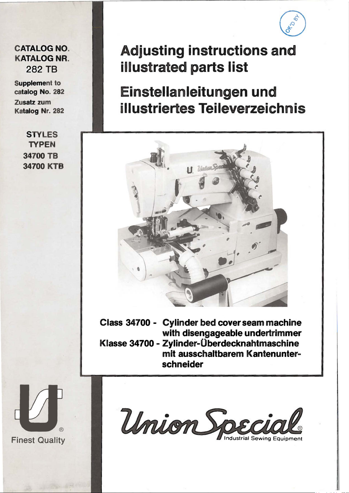
Class 34700 - Cylinder bed cover seam machine
with
Klasse 34700 - Zylinder-Oberdecknahtmaschine
mit
schneider
®
Finest Quality
disengageable undertrimmer
ausschaltbarem Kantenunter-
Page 2
SECOND
ZWEITE AUFLAGE
EDITION
Subject
Anderungen
DA 2333 EG
to
change
without
vorbehalten
6.82
1.0
notice
Printed
in
West
Germany
©
Union
Special
GmbH
1980,1982
June
1982
Page 3
TAULE
lNIIALTSVERZElCI-INIS
OF
CONTENTS
Page
Seite
Th•·e.•ding
Einf:idelanleitung
Identification
Bczeichnung
Inst•·uction
Anleitung
Adjusting
Einstellung
Setting
Tl'immet·,
Einstellung des
schneidet·
Setting
Needle
Einstellung der
die
Adjusting
Einstellung
Exploded
Explosionszeichnungen
Diag•··•m
of
de•· M
s fo•· Mech anic
fil•·
Mcchanike•·
the
Edge
des
Kantenunte•·sclmeide•·s,
the
Sheat•
Adjusting
Schet·winkels
s ,
Einstelfung
the
Edge
Cooler and
Druckel'fuBsohle
Stoffuh•·ung und
the
Tension
det·
Spannrollen
View
of
· · · · · · · · · · · · · · · ' · · · · · · · · · · · · · · · · · · · · · · · · · · · · · · · · · · · · · · · · · · · ' · · · · · · · · · · · · · · · · · · · · · · · ·
Mach i
asc
Angle and
Guide and
Rear
Pa1·ts , Pat·t
nes,
Application
hincn,
Uncle•· Tl'immc•·,
the
, Na
Hinwe
the
Dis
des
Tension
delkuhlung und
Rollet·s
de•·
Late1·al
engaging
und seitlichen
Ausschaltmechanismus
the
Ela
Rolle•·
der
and
und
Einstellung des
Number
Einzelteile, Teil
of
Catalog,
is e fil
•·
die
Setting
Einstellung des Unte•·-und
Cutting
Mechanism and
stic
Guide,
Gummifuht·ung,
hintet·e
Setting the
s a
nd
enummet·n
Styles
Benutzung des
the
Lowet· a
Pt·essut·e,
Schneiddruckes,
Description
Setting the
und
Setting
Einstellung des
Spanm·olle
Uppe•·
Knife
Fingerschutzes
und
of Machines,
Kataloge
nd
Up
pet·
Disengagin
Cloth
Ausschalten
Einstellung
the
Presse1·
Finger Gua
fi:i1·
s
Beschreibungen
Needles
s ,
Maschinentypen,
Knife
Obet·messers
the
Hold
Down
des K ntenunter-
des
Stoffniedet·halter
Foot
Bottom
Anschlages
rd
das
Obermesset·'. ' ..
· · · · · · · · · · · · · · · · · · · · · · · · · · · ·
· · · · · · · · · · · · · · · · ·
Edge
Undet·
Plate
Stop,
fUr
· · · · · · · · · · · · · · · · · · · ·
Na
'.''.'
deln
3
2
-
4
'''''
S
-
6 - 9
· · · · ·
'.''
. . '
10-19
6
7
8
9
·'
''
..
Needle
Qu
Nade
Quick-odet·
Needle
Nadelklihlung fil1· Maschinen
Numel'ical i
Auf
Cooli
ick ot·
lkuhlun
Cooling Devi
welche•·
ng
Kobold
g fUr
Kobold
ndex
Seite
Device
for
Clutch
Maschinen
Kupplungsmoto•
ce
for Machines with
of
pa1·ts
fmde
Motot·s
ich
Machines
mit
Quick-Elektt·onic
mit EFKA
Teile
und ihre
with Quick-
·
EFKA
Stopmoto
Abbildungen
Elektt·onic
Stopmot01·,
Elekt•·onic Needle Pos
•· · · · · · · · · · · · · · · · · · · · · · · · · · · · ·
Needle
· · · · · · · · · · · · · · · · · · · · · · · · · · · · · · · · · · · · · · · · · · · · · · · · · 2
Pos
iti
onet·,
· · · · · · · · · · · · · · · · · · · · · · · · · · · · · · · · · · · · · · · · · · 20-21
ition
e r
22-23
4
-1-
Page 4
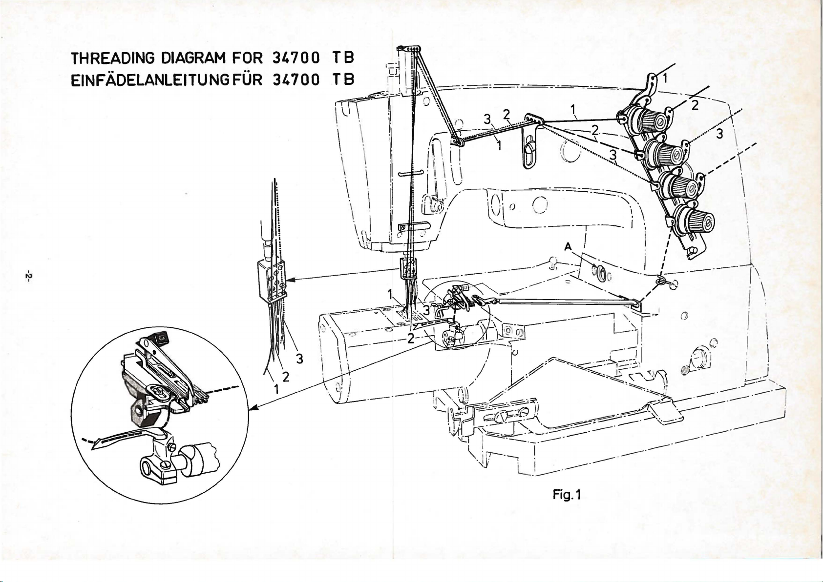
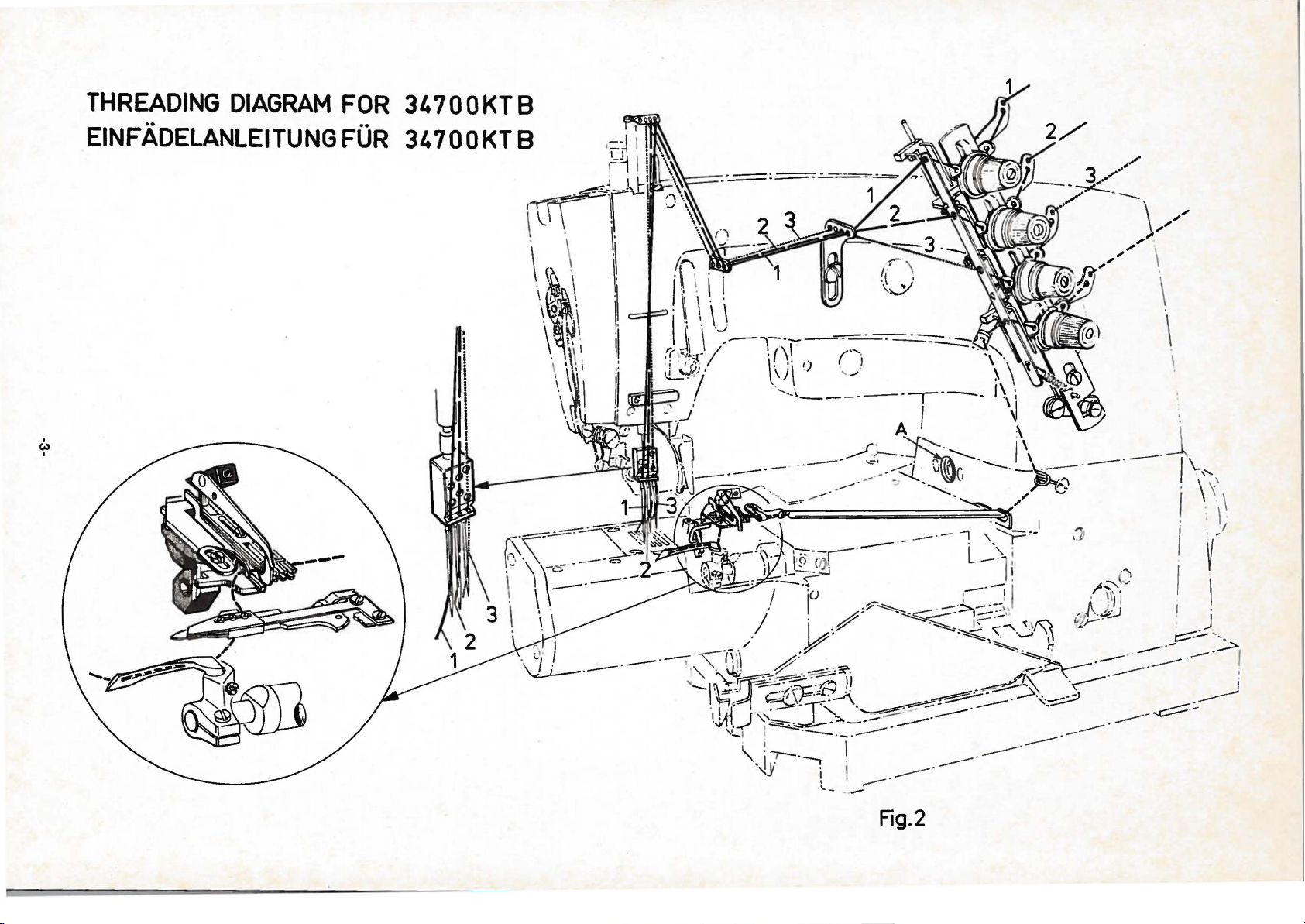
THREADING
DIAGRAM
FOR
34700
TB
EINFADELANLEITUNG
I
N
I
FUR
34
700
'-'o:::--...__2.
....
_~
__
,
...
~·-..;_
,
~~
......
:'
(
I
...
"-""
,
J
·I
\
___
......
3
~
........
······
,
......
Fig.1
Page 5
....
~z
LJJ.
c:=LL
oUJ
<(
z<t
_
t!>z
Q-1
_IJJ
~!::
:l:C!)
<(Z
c:==>
LLU..
O::::l
~~
M M
-4' -4'
I:' I:'
0 0
0 0
~~
Olal
..........
-3-
w
•<(0
_.
I \
~
\
\
\
,
-
·
-
·-
-
·
Page 6
IDENTlFICATION
E.tch
UN
ION
numbct·
a
rc
cl.tsslficd
numbct·s h.tve
contain
Spec
ht! St y
When
chine,
Ex
ampl
Styles
undet·
numbet
Example: "C
APPLI
This c.ttalog
should
pat·t
s used
Style
s 34700 F a
the
b.tck
illustt·ation
the
it· p;
pieces t·c
refet·ence
position
numbct·
Alway
SPECIAL
on
·•
name
the
lcllet·
le
numbet
onl
y minot· cha
a "Z"
is
e:
"Style
of machines
a Cla
ss
·,
in th.
la s s 34700" .
C ATION
is
be used in
on
of
this catalog.
will
11·t
numbet·s,
quit·ed.
numbet
of that p.
s s
hould
s u
se
the part
as
one
suffixed
34700
numbet·
tt
OF
a s
Style
nd
be
·s
ncvet· be used in
column.
References
back,
while sea
etc.,
to
at·e
ted itt
dit·ection
given
the machine.
Opct·ating direction
OF
MACIIINES
mac
hine
on
lettet
the
nd
·s
is
special.
suffixed,
plate
st.md
more
;lt·d a
"Z". Ex.tmple:"Styl
·s
cont,tin
the
nges .11·e made
to
the Sta
KTBZ
- 16" .
simil a r in
is
contains
which
construction
diffm·s fi'Om
no
Jettm·s.
CATALOG
upplement
conjunction
s 34700
KF a t·e
found
to c.ttalog
thet·ewith .On
TB and
illustr.tted and
On
the page opp
" lis
tin
description and
Numbet·
only, and
trt
in the
s in
the fit·st
merely
illustratio
numbct· listed
s ,
such
ft·om
of handwhc
it
the
el is
identifi
hine.
ed
Style
m.tc
Standard
but
e 34700
lett
et·
"Z".
in "
st • .mdat·d
ndat·d
Style
No. 282
KTB
but
g o f
the
parts with
the number
col u mn
indicate
n . Re fer e
01·dering p a t·
in the
S
right,left,front,
operator's
clockwise
by
..t
numbers
never
KTB
number.
are
grouped
the
Style
and
ly
those
not
list
ed
osite
are
the
nce
ts.
second
position
.
Sty!
Style
- 16
at
the
of
ma-
on
BEZEICHNUNG
Jede
UNION
a
uf
dem
Firmenschild
nummern sind
Typen-Nummern
11
•
j
edoch
nie
der
Speziai-Typennummet
Wenn a n
einer
vorgenommen
nummer
angehlingt.
Maschinentypen gleichartiger
Klassennummer
nummer
is
HINWEISE
Dieser
t.
Beispi
Katalog
dadurch
el : "
FOR
Verbindung
fur
die
schinen
Teil
Maschinen
34700 F
dieses
Bildseite geg
nis
der
benotigten
s
Abbildung
bestellungen
Te
Teile
Anzahl
ind
Positionsnummern
zu
il
nummer
Die Richtun
beziehen
sich auf
aus .
Die
Drehrichtung
DER MASCHINEN
SPECIAL
Maschine
der
in
Standard
sind
ein
Buchstabe
·n
enthalten
Standat·d-Maschlne
wurden,
wird
Beispiel: "Typ
zusammengefaBt,
unterscheidet,
Kiasse
34700".
DIE
BENOTZUNG
ist
ein
esem
Zusatz
verwendet
mit di
34 700
und
logs
KF
abgebildet
Kata
enuberliegenden
mit Tell
nummern,
von
Teilen.
und
fin
den
vet·wendet
det·
zweiten Spa
die
des
ist.
wie
Sicht
Handrades ist
nie
in
gsangaben
ist
Maschine
und
oder
"Z".
durch
gekennzeichnet.
Spezial
mehrere
Beispiel: "Typ
den
Buchstaben
nur
ein
"Z"
an
34 700 KTB
Konstruktion
die
sich
daB kein
DES
KATALOGS
zum
Katalog
werden,
TB
und K TB
verwendet
und
Seite,
werden
aufgelistet.
befindet
Beschreibungen
Nummern
zeigen
Jediglich
Positionsnummern
werden. Verwenden
lte,
rechts,
vom
links,
Platz
der
im
eine
Typennumme
Typen
eingeteilt.Den Sta
Buchstaben
34700
angehlingt,
KTB
"Z".
geringe
die
Veranderungen
Standard-Typen
Z-16".
von
Buchstabe
Nur
aber
in
vorn,
werden
Nr.282
nicht
sind
der
wo
durfen
unter
der
Typen
und
die Tei
fur
im
hinteren
Auf
sich
ein
und
ersten
das
Tell
bei
Sie
immer
hinten usw.
beigefu
le,
die
der, der
Verzeich
der
Bedienungsperson
Uhrzeigersinn.
ndat·d
- 16
einer
-
mull
die
Ma-
Spalte
in
Teile
r
-
-
det
die
-
".
gt
in
-
·
·
-
STYLES
Two-and
chines
sewing,
suction
main
E
f
or
Fully
34700
34700
OF
three-needle, cylindet· bed
with
Pneumat
device for chip dis
and
diffet·enti
asy
and
simple
threading
automatic
TB
wide
neously
Fot
preclosed
trimming
KTB,
thread tri
At
the
ad
end
trimmer
plate
thre
throat
MACHINES
undet·trimmet·,
same
mmer and
secured aga
Needle
the
three
chine
chine. Seam
gauge
two
needle machines
needle machine,
can
also
specification
Standard stitch
Cylinder
380
Maximum
on
circumference
mm
( 15 i
speed
operation.
nches).
ica
lly
al
threadin
the
looper.
lubrication
· atta
chin
ela
as
of
the
cuts the
in
such
inst
Nos.10
be
u s
r a
nge
5500 sti
disen
operated
pos
feed
.
g .
.
g 10 - 30
stic
to
the edge
34700 TB,
wiper
sew
in g
thre
a wa
unravelling.
(3,2
mm)a
and
The
16 g
ed
as
a 16 gauge
406 LSa-1 or
1, 6
to
including
tches per
gag
eable
needle
al .
Quick
Flip-up
cast-off
mm ( 13/32-1
undet·wear,
of
the
except
for
the
operation
ads
right
y, that
nd
12
No.
16 (
auge
3, 5
mm
rear
minute,
covet·
cooler
fabric.
with
needle
the
the
(4,8
6,
4 mm)
three
two
407
( 8
guide
seam
during
and
change
plate
while
"KLIPP-IT"
threads.
"KLIPP-IT
below
stitch
mm)
needle
needle
LSa-1.
to
16
rollers
depending
ma-
for
3/16
simulta-
the
is
for
for
the
ma-
ma-
SPI).
in.)
MASCHINENTYPEN
Zwei-und
kantenunterschneider,
Messer.
Haupt-und
Einfache
faden
Vollautomatische
700
34
ringen
Stoffkante.
34 700
schneider
"
ende
Faden
gegen
Nadelentfernungen
bei
den
Dreinadei-Maschine.
a
uch
bild
1,6
bis 3,5 mm.
Zylinderumfan
380 mm.
Maxima
der
Nahoperation.
Dreinadel-Zylinder-Oberdecknahtmaschinen
mit
wah
rend
Druckluft-Nadelki.ihlung und
Diffet·entialtransport
und lei
nach
chte Einfadelun
oben
ausschwenkbar.
Schmierun
TB Zum
KTB,
Annahen
an
Unterwasche bei g
wie
34 700
und
schneidet
dicht
Fadenzieher fur
der "KLIPPAB" Fadenabschneider
unter
von
TB,
der Stichplatte
Aufziehen gesichert
10
gauge ( 3,
Zweinadel-Maschinen
Die 16 g a
als
16
gau
ge
406
le
LSa-1
Stichzahl
Zweinadel-Maschine
oder
407
LSa-1.
g ei
nschlief!Jich
5500
Stiche
g .
jedo
des Nahens
Schneidabf
Schnellverstellung.
g , Ab:.;ugsplatt
10 - 30
mm
leichzeiti
ch
mit "KLIPPAB
die
Nadelfaden.
so
ist.
2 mm)
und
uge
und
16 gauge (
Dreinadel-Maschine kann
eingesetzt wer
Standard-Stichl
der hinteren
pro
Minute,
e fi.ir
brei
ten
gem Be s
ab, daf!
12
gau
6,
4 mm) bei der
ang
Umlenkrollen
abhan
mit
Stoff
versenkbarem
alla
bsaugun
Greife
g .
r-
Webg ummi-
chneiden
11
Fadenab-
der
Am Naht-
die
der Sti
ch
ge ( 4, 8 mm)
den,
Naht-
enbereich
gig
von
-
-4-
Page 7
Op el'
,Jling
P l'e SSlll ' e
needle
fo•·
fo•· chip dispos.•l
fo1
·
cool e •·
•
.l
·e
sse•·
fool
lif
p•
( "KLIPP- IT"- styles wit h
Ail· consumption
of
need
le
coole•
·
of chip
,, l J
OO
dispos
% o
On the p•·e
th
e ope •··•
5
0%,
i.e.
( 0, 28 cu. f
11,5
Nl /mi
ling
<~ppr
al ••PPI'OX.
pe•·,,ling lime.
v.dlin
g m>Jjo l'i
time of the sewing
the .d1·
l.
I m
in.)
n. (0,
•1 c
•IJ}Jl'OX,
p}H'OX.
.!
ppl'
lel
'
o x.16
~3
ly
consumpt
fat· the nee
u.ft./mi
0,2
bar ( 3
3,0
QX,
N
N
of
bdl'
4,0
b.JI'
EFKA -
posilioning
l/min.(0
l/min. ( 0, 8 cu.
the
sewing
m.tchine
ion
is
less than 8 Nl/
dle
coole•· .mel less than
PSI)
(
<13
PSI)
(56
PSI)
mota•·
, 56
cu.ft./min.)
fl.
/min
oper<~tions,
is
less than
n . ) fa•· the ch ip disposa
. )
min.
only)
l.
Zum
Betrieb
dieser
AL·beitsdruck
fi.it•
Na
delkiihlun
fiir
Schneid.lbf;lll-Absaugung
fu r
DriickeduBliftet·
(nur
bei
Luftverbt·auch
fil•·
Nadelkiihlung
flit·
Schneidabfall-Absaugung
bci
100
Einschaltdauer.
Bei
det·
die
iiberwiegenden
Einschaltdauer
Luftverbt·auch
und
unter
11, 5
Maschinen
g
wird
etwa
etw
Druckluft
a 3
etwa
"KLIPPAB"-Maschinen
etwa
etwa
Meht·zahl
det
· Niihmaschine
liegt
untet·
8 N
Nl
/min.
fur
1/min.
die
Schneidabfall-Absaugun
be notig
0,2
bar
,0
bar
4,0
bar
mit
EFKA -
Stopmotor
16
Nl
/min.
23
Nl /min.
der
N;ihoperation n liegt
unter
50 %, d
fur
die
Nadelki.ihlun
l.
)
.h. de•·
g
g.
Add-on device
oiS eXli'
2')')30 A
s fa •· 34700 T B a nd
,J
OI'Cle1· ollld Choll'lje
djust.1b
on
ing .mel g uidinf.l
s i
m.
tchi
Each
ope1·ating
el.1slic
\\ll
?9682
IV
Fing
e•· Gu<
whe n C lo
not use
d .
NOT E : When •·
73
1, fing e•· gua•·d .t
34
h
.ts
to b e used.
311353 B Main
Feed
f•·om 1, 6
per
inch).
NEEDLES
E.
tch
UNION
numbe•·· The
point, length,
size
numbc1
l;:11·gcst
a
mm
betwe
SPECIAL
type
· ,
st.tmped
dia
mete1·
•·espectively
en sha
nk
gt·oovc, finish
numbe•· t·ep•·esent
on
the label
UNION
The
nd
3<1700
a
sc•·
iption
sl.md
of
SPECIAL.
a1·d
recommended
KTB
and
size
Type No.
121 GUS
Round
ljl'oove, blade
s t1·uck g
Sizes
To h a
ve nee
.tn
empty pack
size
number should
label . A
' 1000
Se
lection
of
th1·cad us
edle eye
ne
dle 01·
complete
needles,
of
prope
ed.
in
age , a s a
o1·dcr
it ems :
le T
ension
ne
insti'Uclion
h T
n·d
th
Hold
to
4, 5
Roll
er
of
es
p•·eclosed
she
includ
s fat· atta
ension
Dog
Rolle•·
f01· Unde•·trimmer,
Down Pl ate· Part-
cmovin
g cl
oth
ssc
mbly
lloldct·
mm
needle
fa •· a
( 5 1/2
has
Device
et
both a type
numbe1· denotes the kind
and
on
the
of
blade,
in
and
the
all nee
thousandths
eye.
complete
dles
measur
Collect
packaged
needle
ed in
of
ive
symbol,
needle
is
Type
121
round
GUS.
point,
s a
V<~ilable:
shank,
increased, ball
roove,
70 / 027,
ders
ord
Type
r n e
Thre
80/0
p1·omptly
mple
be f01
·warde
er w
121
edle size
ad
should pass
to pt·
oducc
chromium
32,
90/036.
and accurately
needle,
d. Use
ould read :
GUS, Size
is
det
a g
KTB,
avnila
ble
fo1· ten
elnst
ic ,
No.DA 2343
ching pt·eclosed
Device.
necessar
No.
34731 is
hold down pl ate
pa1·t
No.99682
stitch
16
r ange
stitche
to
and a si
of sha
othe•·
details.
sh.mk,
denotes
hundreds
an
inch,
ly,
type
and
for
Below
ball
Styles
and
which
sold
is
the de-
tip,
midway
is
by
34700 TB
eye, spotted,
plated.
or
the
type
description
80/032".
ermi
ned
freely
ood
by
throu
stitch for
-
with
y
s
nk,
The
of
size
given
double
filled,
and
on
size
g h
mation.
W
Zusatzger
zusii
tzliche
29930
99682 W
34353 B
NADELN
ze
Jede
UNION SPE
nummer. Die
bens,
der
andere Einzelheiten.
pragt,
hundertstel
in
der
nummer
die auf
und
verkauften
Die
empfohlene
und
34700
Sie
die
Typen
121
GUS
Urn
Nadelbestellungen
senden
del
ein,
na
B
enutzen
Na
delpackun
uten:
Ia
Die
Wahl
des verwen
Na
delohr gleiten
l:i
te
fiir
34700
TB
Bestellung
Einstellbare
und
Spannrolleneinrichtung
Webgummiringes.
Jede
t·
Maschine
Anleitung
mit
der
Spanm·olleneim·ichtung
uber
liegt
das
Fingerschutz fur
der Stoffniederhaltet·
wird.
BEACHTEN
nicht
schutz
Halter
von
1,6
SIE:
verwendet
Teil
Nr . 99682 W
fur
Haupttransporteur
bis
4,5
CIAL
Wenn
wird,
mm.
Nadel
Typennummer
Spitzc,
gibt
Mitte
zusammen
jedem
der Lange,
den g
roBten Dur
Millimeter
zwischen
ergeben
Etikett
Nadeln
Die
Dickennummer,
bzw. in
Kolben
von
steht.
Standardnadel
KTB
ist
die
Type
Beschreibung und
Nr.
Rundkolben,
Ri
nne
n ,
gepragt,
Dicken
Schaft
verchromt.
70 /
027,
Rundspitz
verdickt, Ohr verdick
80/
richt
Sic bittte cine leere
oder geben
Sic dazu d ie B
g . E
11
1000
Nadeln, Type
der richt
deten Nahf
ine
ige
urn
voll
eine gute
Sic Typen
eschre
st andige Best
n Nadeldick
aden
und
KTB,
erhJltlich
Bet·echnung:
ein
Druckblatt
Annahen
von
bei.
Unterschneider,
Tell
Nr,
34731 n i
der
Stoffniederhalter
mull
der
komplette
eingebaut
fUr
hat ei
ne
bezeichnet
Typen
die
der Rinne, der
chmesscr
der
tausendstel
und
Ohr.
die
vollstandi
durch
UNION
fiir
die
121
die
erhaltlichen
Maschinen
GUS. Nach
e , Ku g
032, 90/
ig und pro
036.
mpt ausfiih1·en zu
Nadelpackung od
nummer
ib un g auf dem Etike
ellun
121 GU
S, Dicke 80/0
e r
s . Der
Fad
ichtet
en s
Stichbildung zu gew
gegen
zum
Nr.
Fuhren
DA
de
2343 mit
Webgummiringen
notwendig
cht
wenn
verwendet
34731
Finger-
werden.
eine
Stichlange
und eine
Art
des
Dicken
Nadelkol
Oberflache
im Na
delkolben
Nadelklin
inch an,
ge
gem e s
in
Typen-und Dicken
ge
Nadelbezeichnung,
SPECIAL gepackten
34 700
folgend
TB
finden
Dick en :
elspit
ze zwei gera
t , H
ohlkehle
konnen
er ein
Dick e
e Mus
an.
und
tt der
g wii
rde
z. B .
11
32
•
sic
h n ach
ell frei dur
der
ch
das
ahrleis
und
einge
sen
-
de
ter
St a
ten.
-
-
-
,
-
rke
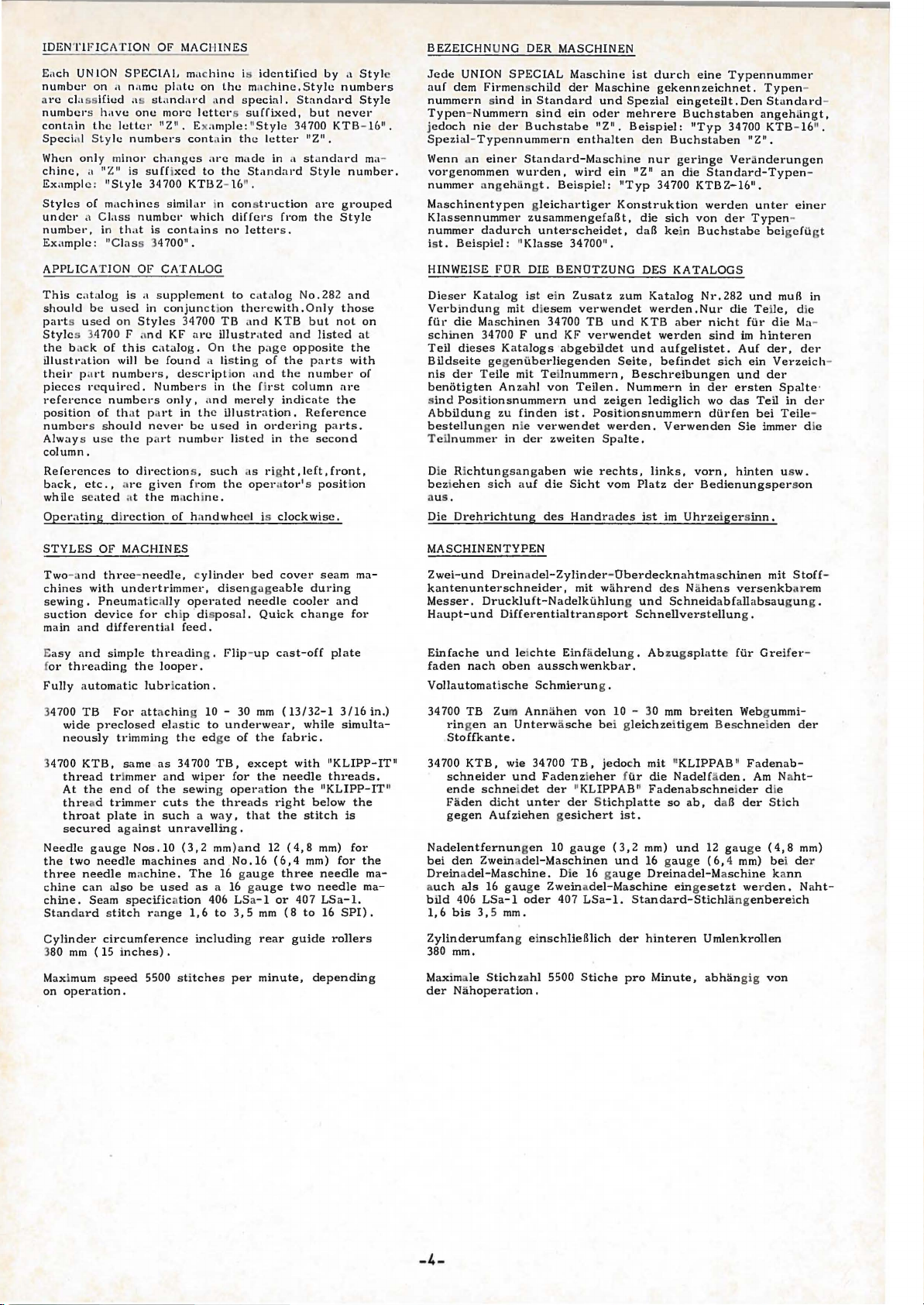
T HR EADING
he 3-nccdle
T
Fig
.1
and Fig
Fig
.1 shows
"KLIP
Fig . 2
"KLIPP-IT"
F
or thr ea din g t he
th
readin g
parag
raph "THR
the
P-IT"
is threa
shows the ma
is
and
machines
. 2,
sec
manner
ded.
nner
threaded.
two
cleanin g '
EADING" in
are
threaded acco
pag
es
2 a
in whi
in whic
needle mach
the
cas
cata
nd
3.
ch
a machine
wit
h a machin e wit h
in es as we
t-o
ff
plat e refer
log
No.
282 .
rd in g
ll
as for
to
hou
to
t
EINF.i\D ELN
Die 3-Nad elma
siehe Seit
Fig . 1
ze
schinen werden
en 2 un
igt das Einfade
Fig . 2 zeig t d as Einf
Einfadeln der
Fadenaufnehm
der
Katalog Nr . 282 .
Zwein
d 3 .
adelmaschin en s owie ei
erpla
-5-
nach Fig
ln
einer Maschine ohne 11K
adeln einer Mas
chi
tte slehe Absc
. 1
und Fig . 2
LIPP
ne
mit 11KLIPP
nfadeln
hni
tt 11EINFADELN" im
und r einigen
eingefa
AB
11
AB
•
delt,
11
•
Page 8
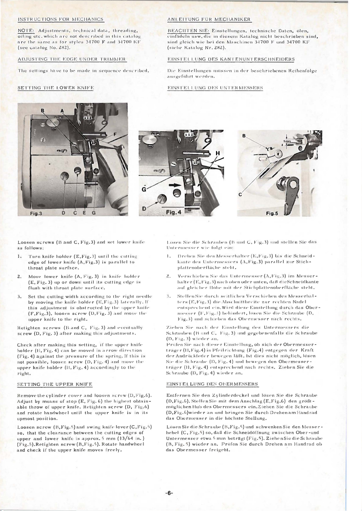
I SIHUC
NOJ'
J'IO
NS FOH
E :
Adjn~tnwnt~.
oilong etc .wl11c h .11·e
a r
••
tlw s.tme ·'" fo
(s •e
<.at.olo
g N
o.
lH2).
AD.J U
SJI
NG
1111~ I·.DGI~
~IECIIANICS
lt•cho
oo.:
not deS
o· stylt•
b 3•17
.ol
<1.11.1,
<I"Ibed
1l0
tl11·e.od1n~,
111 tl11 t•.tt.ol
F
.tnd
3·
1700
og
I' F
ANI
E l r U
NG
JII~ACII
t.•tnf:,dcln
s ond g le1 c h
(s
ot
•lu•
J'I!:N
u~w.
woe
K.11.tlog
SIE:
E INS I le i I lJNG
F UH M ·
E o
n,;tellnngen,
d ' c
1n
l>t'i
den
No·.lHl).
Df:S
CIIANlKER
te hnis
d
ie~ctu
I,,, til
~J
as~lnnen
KAN
J'ENUNTEHSC II N E JDF:
log
3·
n1cht
1700
c h c
Daten
besLhriebcn
F
nnd
, d lc n,
3
4700
HS
s ind.
Kl
·
SE
J'TI
G T
IIF: I OWEH K IFF
Loosen
11s
I.
2.
3.
~
sc
Cho
S<.rews
follows
.
Tu
rn
knife·
edge
of
throat
plate
Mov<'
lower
(E,
F ig .
flush
w 1
Set the
by
th
(F,Fi
upper
ctighten
rew
•c k a
movin14
i s
.LdjustmPnl
g.3
knife
scrt•ws
(D,
Fig.
ftPr
cutting
lower kni
3)
th
makin • this
holdt>r (II, F ig .
(F ig .
4)
ot
possihlf",
ht.
a g:tinst
knif<'
hold•·r
n
upp<'r
r i g
(II
holder
up
throat
til<'
),
loos•
to
3)
4)
thP
loo!-H' n
and
C,
(E,Fig.
fe
snrfac<'.
knife•
(A, J•'1
or
down until
plait• suo·f.Ht'.
width acc
knif<'
is:
·n sc rc•w
lht• right.
(II
and
dfter
rn:tkin
t·
an
bt>
p r<'>lSllr<·
screw
(II, F og .
:
Fig.3)
.1nd S
<'l
lowt·o·
3)
nnl
il I
he
(A,F"ig.3)
14.
ordin
holdt•r
obsl
ructPd
(D,J·"i
3)
t
l~
(Jo:,
is
14
g.
t uti
P·"·;dl
e l to
in
lu111t- holclc•r
cutting
to
tht•
P
rq.:ht
F og. 3 ) J.ot•· r .
by
tlu
• uppt· r l
J ) .
tnd mo
C , J·'1g. 3) .1nd ••vc•ootu.tll
g tin s
.tdJustnH·nt
~Piling,
n1DVl
if
tht•
..
d in .1
rs·ow dirPLIIOn
of the spring .
(D,
F1~
.
4)
4)
a~corchn ~
npJH'I"
If
.
1nd n,OVt<
ly
to tlw
dgt
kn oft·
in
'
lll}.
vt· t
s .
knift·
tlo
g
1
~
m·l'dlt
<.
uift·
y
is
ll
u·
D tl' Etn
o1
I
lJ
I.
l.
I.
•
If
it<
•
i'.ll'ht
SLitraulwn
(n.
fJI't l
l
is
de·•
S o
tr,
St
:-;
n
oS4'tt
illt•f'IIH'..,..,t'l'
tt'llungcn
r;
l!l'ftth
1'1
'' t't'dt·
S i t' <fi•·
11rt
• l~t•
n
k.J
U I P dt·s
Jll.tli''''',J,t•J•II,,Lilt'
V••J':-tt ),,
ho~
It
c· r (
.Htf
F:
glt·Jt
Stt·llt·nSrt·
l•·
o·s
( 1
':
,
l'lllspn·tl
ll
lt'~:o.t·
t ·
F1g.
:S
) und S l
•n
S~t•
(II
J•'og .
:S
) " ;,.
ft•n
SiP
" r
(II,
rill'
S<.ltratol><
t•r
(II.
o11he
ll.lt
,.-,1(.4)
h.
. klt·d t· r
l-'1g.
(D , F i
rot!(<
· 1\nclrc
t·
' g
h r.
1\III~!'lt'll
n.
s,
hr.tnlH
\\ )('
lo)
S i
t•
dt•n
nlt•J"JlH'S'!·H
,.),,.,,S
it'
,
1-'i
Lt
· l )
lu·1'
llnht•
durt.:h St' Jllll ht·s Vt•,·schu•ht·n
J.'o
g . I)
clOt• ,\!Jst
ll·nd
t'l
(I
·
.l·1g.
lt
lt•ln ·
n.at.h
dt•r
11
nrl C ,
cJ,.
r
""·
h
cl
l f' S
on
pf,.oJ o'O<
h<-"wPgt·n
·
(n,
4)
t'llt:-,pl't't
g.
4)
1
11
d
... ·.-hc::,ch r
I I·.H
~JF:SsE:H S
·n (J', n
ud
gl
t'
I U :
~j,.,
·· · o·lo.tllt •o·{I
st t•l t
f),,
:-
nol
l" h oiH·n
111il dt•J' S
n.Wi1·rl
J )
IH·IItnclt•J'I,
ll
rl.1
i-:111:-,
J.'
og. 3 ) >llld g<'l(t' IH•n•·nfnlls d il'
t·r
l~lnslc•lh,ng,
F o
14.
"i<·dt
(..,I· :g.1)
·r·s
(A
,F'Ig.3)
l.
l tll t'I" Jllt
lot
4)
lu•nd n.lt.h
'SSt•r (,\,Fi
ud<>
,.
lit hpl.!lll•nobt·rfl,i.Lh(' S
ltn otl
Joo
·•
dit•st
• l;:lnSlt•llung,
lost•n Sit'
s
Oln·n11t
tt·ll
llng
dt•s
ung
(Fog.4)
ltl.l\1.
bt
to
llll bt·\u·g o·n
•r .on.
tcbencn Hci
11
11<1
:..,F>
•.
3) IJ1s
Jloll'.tllt
en,
J,t
d.t"
unl
dt•s
itt·
7.110'
o·•·•
du · :
sst• r
n.
u: h
Unlt•rn
ob
sich
dPr
<'nt g <'l(<'n rlo•r Kra
clit•s
nicht nl<lgfich,
den
rf'l
Ohe
ht s. Z
hcnfolgc
S!t•lh•n
Sit• da.s
ri
ll' Sc howo
•l :ln r St i
. 3) 1rn "-l• ·s
rh <•
htt·n
clurc
iP SS
cii-
S('
hnl'iclka
"-h•s!it•rhal-
Nadt•l
h
ci
il S Obcr-
chrau
bt:
r·t•t.
h
t.
,
('r
H
cht>
lt-"ht.
St hrau
Obt•rn1t"~hPr
lthH•n
r m e
ssPr-
H•ht-•n
Sit.•
d-
ser
nle
(D,
lw
ft
eli~
-
lNS
I' E L L U
(C ,
S i
SLt-llt•
lluh do·s
Fig.">
s o• r
wic
e s
NG DES 01\EH
o·
dt•n
Z y
lindt
nSi"
mot
OIH'rnws~ers
P r
an
nnd
in
di<' hi
) s
o,dall
Ptwa
">
mm hctr1igt (Fig.">). Z ieht•nSie d J
d<' r
an.
ser fro
•i g
S E
TTING
R!!
movo·t
A
dju
s t
ble
nd
by
throw
rotat<'
a
a
upmobt pos
oosen
o,
nd
that
che
screw
and
).R<'t
c k i f
L
s
upper
(F l g . 5
a
filE
UPPEH
ho•
<.yltndt•r
means uf
stop (E,
o f UJ1lll'r
handwhco
ition
•l
.
(1\,Fig.~)ancl
the learanc<'
lower
knife
i g
hten
screw
the upper
KNIFF.
covt•r
kmfP.
until
betw<·
is
(R,
knif<'
and loost•n
F i
g.
I>)
ghl<"n
tlw
sc
Ht'li
the upper
s w m g knif
c n t
he cutting edgo•s
approx. 5 mm
F1g.">
).
RotatP
mov
es frPPly.
" ' rt·
h ol(hPs t
rPw
knif<'
<'
lever
(
13/64
handwhet
v.
(D,
(D,
is >n o
(C,
I·'
ig.b).
obtain-
F ig .l>)
F 1g .">)
of
1
n.)
•l
E
Entfo•rown
(D,Fig.b).
miigliLh<'n
ts
(D,FigJ>)wH•d
rl.1s
Ohernwss t' r
LosPnSio·rli<"Schraulw (li
lwho·l
Unto•rm!'s
( H, F ig .">)
das
Oberm
-6
-
M F.SS
EHS
•rclo·c
k<•l
d<'m Anschl.tg (E,
<'in.
brm
g<'
n Si<'
khs
te S te
,Fi
g .<,)
o•
Schneidoff
ufe
n S ic
und schw
durch
d i
P r
<'ht.
unci
loi
s t•n S iP d l P s,·hra!I
F ig
Z oehcn S
durc
hDr
llun
ehena
g.
enkenS1c
nun
g Z\\ibc
Drchen a m H
.6)
den groHlt-
ic
d ie Schra
hen
m Handr
den
ll.lc s
Obe
r - u
<' Schr.tull<'
and
rad
IH'
ulll'
a d
s<•r
·
nd
oh
Page 9

SETTING THE
LATERAL
Both
and
possibl
of
the kni
Adjust
(J,Fig.6). Turning
cutting
the
reverse.
To
adjust
F i
g.
on
the
lined
Turning shaft
the
shear
decreases
make
"Setting th.e
D
ISENGAGING
Press
will
on
thefrontofthe
so
it
unt
i l
This
the
edge
lever
settings
should
e , i n
the
pressur
3).
Set
shaft
up.
sure that
lever
go.
Then
wi
ll
the
slightly
lockes
under tri
(B,
CUTTING
depend
be
kept
ord
ves
.
lateral
the she
shart
and mark
(F,Fi).t.
angle, turnin
it. Retighten
upp
(13, F ig .
press
move
the
F i g. 7) e
SHEAR
e ,
the settings d e s r ib ed in
e r
T HE
very
ANGLE AND
PRESSURE
on the fabric
as sma ll
e r
not
cutting pre
the
nut
turn
ing it c
ar ang
(F,
F ig .
(K, Fig
6)
knif
e "
EDGE UNDER TRIMMER
7)
slightly
cylinder.Now
slowly against
pressed
upper
knife
mmer
ngages
respectively
to
shorten the s ervic e
ssure
c lockwise mcreases
ounterclockwise acts
le
loosen s c r e ws
6) so,
that
. 6 )
on cylinder are
In
arrow
g
in
it
s c r e
are
is
the
direction
a g
ains
t a
ws
(D
not
disturbed.
arrow
direction
the
push
release lever(B,Fig.7).
push
button
in
its
lowest
disengaged. A short
trimmer
TilE
to be tri
by
mark
rro
and G,Fig.3)and
button
thParrowdirection
(A, F i
agam.
turn
(Dand
(G,
w d i
paragraph
as
g.
position
mm
d
low
a s
live
ing
nut
the
G,
F 1g.6)
increases
rection
far
as
(A, Fig. 7)
7) enga ge s .
and
ti p
on
EINSTELLUNG
SEITLlCHEN
Beide Einstellung
abhtingig
halten
werden,
verringert
Der
seilliche Schneiddruck
(J,Fig.6)eingestellt.
erhtiht
den
ve
rminde
Zur
Einstellung des
(D
und
G,
sich
die
Zylinder
sc
hla
de r
. 7)
chtung
haltet.
Markierungen
der
Si c
g.
Stirnseite
los,
bewe
Das
Kurzes
am
Drehen
Scherwinkel, dre
ihn. Ziehen
beachten
messers"
AUSSCHALTEN
it
DrUcken
An
an
Fig
r i
rastet.
Stellung festgehalten
s c
Kantenschneider
DES
SCHER
WINKELS
SCHNEIDDRUCKES
e n s i
nd
von
und mus
rl ihn.
Fig.
Sie,
sen
so
damit
3) .
hen
die
da B
die
Drehen
Scherwinkels
Stell
berstehen.
in
Schrauben
die
wird.
Schneiddruck,
gegenli
Achse (F, Fig
Sie
be~chriebenen
DES
KANTENUNTERSCHNEIDERS
den
Dann
Hebel
drlicken
des
so
daB
e r
gt
his
der
Obermesser
antipp
wieder
Zylinders.
sich ganz Iangsam
und
dem
kle
in
bzw. niedrig wie
Standzeil
wird
der
drehen
en Sie
die
(G,Fig.6)
entgegeng e
i m
(B,
Sie
Ieicht ged rUckte
de r
e n
ein.
auf
.6)
in
Pfeilrichtung
(D
Abschnitt "Ei
E in s
tellungen erhalten ble
F i g.
7)
Ieicht
Nun
wird dadurch in
Kantenunterschneide
des
He be
UNO
DES
zu
schneidenden
der Messer
dur
c h
Drehen
Mutter
Achse
auf
im
im Ge
ltisen
der
setzter
und
in Pfeilric
ls
Uhrzeigersinn
genuhrzeigersinn
Sie
die
(F,
F i
Achse
R i
chtung verkleinert
G,
Fig.
nstellun
htun
den
Druckknop( (A, Fig. 7)
lass
en Sie de n Hebel (FI,
entgegen der Pfei
Knopf (A,F
sein
(B, Fig. 7) schalte l
Material
mtiglich
mcht
der
Schrauben
g.
6)
und
vergrtillert den
3) w iede r
g d e s Obe r -
g b
e r
unntit
Mutter
so,
(K,
F ig.6)
iben.
is zum
ig . 7) e
unt
e r .n
r i s t
ge-
dall
an
in-
ausge-
den
ig
und
l-
ADJUSTING
Remove
move
unt
i l
it eng
(L, Fig.6)
If
it
is
this
adjustment,
stop
(E, Fig
g
ages.
SETTING THE
Loosen
until
the
(B , F ig .
hold
down
do
g.
Retighten
THE
DISENGAGING
cylinder
push
.
not
Retighten screw
screws
needles
9)
cover. Loosen
button
(M,Fig.6)
ages
as
possible
loosen
.6)
clockwise
CLOTH HOLD
(C
and
are
so hig
h,
plate
(G,Fig.IO) rest s pa
scr
described.
to
engage
screw
(D, Fig
D, Fig. 9). T
in high po
that
the
ew
(D,
screw
slightly
the
(D,
until the p
.6
DOWN
siti
front
s e
F i g.
9).
MECHANISM
(L,Fig.6)and
back
push
Fig.6)
ush
urn
on.Set
ction
rallel
and
e n
button
and
button
PLATE
handwheel
the
of
on
Retight
).
forth
scr
bracket
the
the
ew
with
turn
en-
cloth
fee
EINSTELLUNG
Entfernen
Fig.6)
und
und
her
bis
hraubc
Sc
U !llt sich
rasten,losen
schlag (E, Fig
astet.
r
EI
Ltis
Nadeln
d
F i g .
seinem
aufl
Zieh
NSTELLUNG
en Sie
in thre
9)
so hoch,
vorderen
ie g
t, Zie
DES
Sie
den
bewegen
er
wi e
(L, Fig
der
Druckknopf
Sie
.6)
e n S
DES
die
Schrauben
htichste Stellun
dall
he n
Zylinderdeckel.Lose
oben
.6) wieder an.
die
i m
ie
die
Ber
Sie
-7-
AUSSCHAL TMEC
Si e d
en
Druckkno
beschrieb
dur
Schraube
Uhrzetgersi
Schraube
STOFFNI
(C
der
Stoffniederhalt
eich parall
die Sch
en e inrastet.
ch diese Ei
(D, Ftg
nn bts d
(D, Fig
E D
ERH
und
D,
g. Stellen
e l a uf dem
raub
e (D , Fig.
!+ANIS M
n S
pf (M,F ig
.6) und
.6) wieder
AL
F i g. 9
Sie
er
US
ic
di e Sc h
raube (L,
.6)
Ie icht hi n
Zie
he n
nstellun
er Druc
TERS
). Dreh
g nic ht ein -
drehen den
kkn
a n .
en
de n T r lig
(G , Fig. I 0) i n
Transporteur
9) wieder
Si e die
Ste
An-
opf ein -
er (B,
an.
di e
Page 10

SE:I'
T ING TilE
(ConiiiHicd)
Loosen
(F, l"•g.
enough
bottom,
ra1~e
foot
the cloth
possible
T
upper
s
I S loft e
he
latt!rnl clea
l<nofe s
screw
? ) the l
clc.t
r.tn
when
the t.loth
d.
hold
.obove
hould
(A ,
ever (E,
cc b e
c
Rcti
clown
s co·ew (C , F 1g. ? ) ;
SET
T I
NG
!'li
E E DG E
ELASTIC
GUI
DE
LO'rll
F•g
. ? ) .1nd
tween l
ros~1nA
hold
down pln
g ht<•n s
pl.ote
the
feed
r.on c c
betwe
be
0, mm(.02
oftel
' m n ld ng tins .od
GUIDE AND Til
1101
Fo •. '
eve
,, sc.tn
rcw
(G , Fig.
dog
IJ
DO~
N PLATE
.~e
lju~t
J)
s o , that
r· .Lnd prcsHc
l.
LL·vcr·
tc
whPn th
(A,
~'1g.
? ) :
w itho ut
e n
hole\
0 1n. ).
by me.ons
ther
e 1s j u s t
r fo
(
E,
F tg . 9 )
e press
•!). Now s e t
1s
clo
s e a s
touLI11ng ot.
clow n pl.
otc .oncl
Hct•ghtcn
j us
llll<'lll.
E
o f s to p
ot
er
(Forts
e t z
ung)
Lost•n
S1e d
ie
Anschla~-:
(F , FiJ.:
SLhr.oube
. ? )
d<·s Stoffnocdc·rhnlters
<' 1 11,
clnf!
di e
Droickerfullsohle be11
~'"''•Hi
e
no
< h ll·c i
w•c
rlcr an.
s o d i
chl
bcruh1·t.
•r se11 llc
0,
~
W
111111
t
hn
Dt
s
oli
Sc lu·auhc ( , F
Slt•llcn
ll.
'
rnogli
he
Abst.1nd
bet r.1gcn.
'a).!
J.:ehl.
.
den
lw1m
Ziehen
S1c
Jt'l<~t
ch
uber
zw t sclw n Nic
Z 1
lJ)
w t
cdcr
(A,
F i
g.
'J)
(E,
unci s
F•J.: ·
?), cle r z
IIebel
l1ften des
n U bcrnli
S1c
cl1e Schraube (A,
den
Stoffnteclerh.tll
den Transportcur,
clcrh
chen
Sic n.ILh die s
.tn.
tell
e n Sic m it dc m
Dru
c kc
rfuf!e
hc n e i
e r
ohne
a ll c r unci
cr E1nstellung
um
Anlwb
s dicnt,
ner Querna
F•J.:·
9)
(G,Fig.IO)
dal3
Oberm
e n
s o
ht
dicscr
e!lser
cite
Loosen
to
R<•lighten
Set guid e
to
S
P
L
t
p
Rett
NE
Set
low
air blows
to
p
m
h
Please
o
th
RE
the
the
ETTING
RESSER
oos
e n
hat
the
lait•
surfac<>
ghtcn
EDLE
both
as
1t
that the
resser
achines
ook
must
usly
em,
AR
screw
width
scr
(D,
w 1
dth
TilE
FOOT
screw
presser
screw
COOLEH
needle
possible
directly
foot
with
move
not
e · T
as
a h nger g
also
TENSION
(E,
to
be tri
ew
F i
g.
of
elastic
STOP
(F,FiJ.:. 12)
lw n
cooling
and
left
when
thread
he
when work
ROLL
Note: Tension Rolle
a
nd
char
ge it e
m.
F i
J.:.
II)
and set
mmed.
(E,
F 1g .
II).
13)
and coll
used.
FOR
TilE
BOTTOM
and set s
foot
bottom
the
pr<•ss.-r
(F,
Fig.
12).
nozzles(~
tlw
nozzlt•
a g
ainst
lower
it
tlw
nozzle do
is
in its highes t
wiper (34700 KTB)
freely
below
cooling nozzles
uard.
It
IS
in g w i
thout
ER
r A s s e
mbly
e
d~-:
a r (E, F t
top (G,F1g.ll)
1s
pa
rall
foot
'
and G,F1g
op<'nin
ne<'dl<·h.
c s
the
rig
serve sim
llow
not
needl
is a n
e
MUI(Ie
J.:.
13) ac c
c l
to
IS li ft c·cl.
gs
so,
P
lea~•·
not cont.l
pos
it i
tlw
ht
nozzl£'.
ed
to
e c
ooling.
extra
(D,Fig.ll)
orrl•nJ.:
I he
thro.ll
.ll)
thai
S<"
c l
tlw
on.
On
wipe
ulta nc -
r e move
order
as
the
P
r
so,
Lo
s t•n Su• rlt•· St hr.1ulw
fu h•·u
nJ.:
(D,I·'•g.ll) olllf
11•lwn
Z
Slt
Fi
F:
sc
Dnick ..
Z n · lu •n
NA
Stt
w i
.
s
d<
(3
S u• d it• S Lil
•ll<-n
S11• dt•ll Ans t lda g
~-:.
13) t•nlsprt·
INSTF:LJ.UNG !JF:S ANSCII
DH
UC K E H
st•n
Ld
hlag (G
FUSSOII
S i
••
du· SLhraulu
, F i
rfu
l.b
~it
•
eli••
DE LKUIILUNC.
•ll• · n S u• lu•1d t·
<' mt.,gh!'
tuf
tt•h
•r hiic
di<' Nacl e
Pnd<' H o
hst<
h unci
•n S t cllung i s
4700 KTH)
Hohr frcige lw
Bitte b
eachten S i
als Fi
nge r schu
we
nn
ohn
e N.odelk1ihlun
HINTE
R E SPANNROL
Beach
ten Sie : Die
liche Bestellun
r.luht
Lhe
ncl
dt•r
L E
J.:. ll)
s o t•t
ohle I"' r.tllt
S<hrauiH'
Naclt·lk•ihlrohrt
dit• Hoilrt;ffnun
ln
blil~l.lllll<·
hr
d<>n
Dnickt•rfull
mut:l clc r l'adPn7.J
n.
c:
Die
tz.
S1c di1rfen
Spannrolleneinricht
g u
nd
Berechnung erhliltlic h .
(
Jo:
,
l•'i
~-:.
rllt '
· (
II) unci
1.:'''-'llnschlt'
E,
F tg .
(D,
F tg .
vc•
rwemll"tc n G
II)
I~)
w11•cl" r a
LAGS F UH DI E
• ( F , F i g .
n,
•l
d.dl IH•
:.111
r St lc
( F , F ig .
ll)
11n
1 gPlif
hpi.Jtte slcht.
ll)
w i••
• ( F unci
g<'n s
be.tchtcnSie
n1c
ht
l.
He i Ma s c h ine n m
lw rilhrt, wenn
eherha k e n
Nadelkuhlrohrc di
ntc
~
hl entfcr
w i r
g
g ear
L E
Stl"II P n d
ie
Sloff-
A bs<:hnittbrt•Jie <"Ill.
n.
unci tl<'n Si<'
llr
in g
ummibandbrcite
d slt·llc
ldt
o, cla
n S ic dt•n
•m
D r
uckt•rfuf!
tlt·r
.1n.
Ci,
Fq~
.
II)
~
t:l
dH· L uft d i
,cl
af! cl.t s linke l le fe r -
o
d ie s c r 1n
it F.td
c r
dem
enz
r e c
unl
enen gleichze1t1g
nt
we r den, a
d.
ung
i s t ge g
en zusiUz-
rekt
ie l
uch
(E,
An-
d iP
ti
wr
hten
e f
e i
n.
T
he
tension
to
allow
rolle r
Adju
s t
(K , F ig .
roller
the
operator
according
nuts
(J
14)
clamps
to
and
(L,
F i g .
14)
width
pt
of w a 1
so,
is quic
the
t h
at
pos
to ada
the
H, Flg.l4)
the
roller bracket securely.
kly
it io n of
st
to
the ecc
adju
be sew
ent
s ta
the
n.
n c
ble,
D i e Spannrolle
de
r N llh e r i n d i e Lage
weite
anzupassen.
F ig .
14)
che
r f
s o e i n,
estsp
a n
s 1
(L, Fig .
Stellen S1e
daB
der Exz
nt.
14)
is t schnellverstellbar. D1es
der
Rolle
a n d 1e z u ver n llhend
die
Kontermutte
enter (K, Fig
. 1
4)
den Roll
r
(J
e r la u
e B u nd -
und
H,
e'nh
alt
bt
e r
Page 11

A
DJUSTING
T H E
TENSION
ROLLERS
E !
NSTEL
LUNG DER SPANNR
OL L
Fig.14
EN
.._
__
_ Fig.
For
norm
postt ioned
F ig.
I~)
a g
ainst
thP e l
Fo
r s m
whi
d >rf"ctlr to th<' mac h
SE
(When sewing without
T
Loosen collar
Se t
s
a n
a
wh
be
(.
SET
The presser foot
q
be
of s
Re t i
alle
c h a r c supplied w1t h £'ach
TTING
urn han
the
fin
o,
that whe n
ce
of 0,5 -
nd feed
d og
e n i t
is
twe
en
020 in.
TING
ui
red,
th e s
chan
ge d a c
crew (B,Fig.ll)after loosening n
ghten nut
15
al wid
ths
as shown
so
hig
r wid t
T HE F ING
dwheel
ge r guard (A, Fig
s, and a clearan
in the highest pos
upper knife and
).
Re t ighten
TH E
lop
of
h,
tha
t thP
astic watstband
hs
of waist
ine
ER
unti
l t
s ( B a
nd
it
is
in the
1,0
m m
coll
PRESSER FOO
bottom
e a ngle o f t
cord
ing
(A,
F i g
.ll)
w.tist, llw tPn
in
Fig. 15. Set
upper knife doe s n
ylindcr.
GUARD
cloth hold
he needle s
C,
F ig. 13
.l3)
low
est
(.
020-.040
ce
iti
fin g
er guar
a r a fter maki
is
he
to the
a ft
er maki
sion
the
.
usP
r o
llf'r
machine
by mean
positt
of app r ox
on.
T he l
T B OTTOM
set
a t
presser foot
fa b r
s (S , Ftg. 16),
and
F OR UPPER KNIFE
down pla
are
in hi
).
s of the collars
on
the
in .) between guard
ic
r e i s a clear-
.4,0 mm(5/3
ateral clea ra n
d m u
st
ng th1s a
the fact
to
be
se w n ,
ut
(A,
n g this s
r Qllcrs
r oller
(H ,
ot
push
flxe
te
onl
y)
gh position
be
0, 5 mm
djustm
o r y .
If
bottom ca n
by
Fig
.ll).
ett
ing .
arc
2 m .)
ce
e n
r e -
m eans
.
t.
der Masch
E I
(Nu r be >m N
Dre
Li:ise
St e
s o e i
n
Der seithc
mull
Stellrin
ElNST
Die
ka
Schraube
en
Ziehe n Si e na
a n .
Fig.16
FUr normale Flu
F •g . 15
F
nicht
Fur kl
bc
gezeigt,
ig
.
I~)
gc gc n d
c tne r c B
ige
packtc n S pa
NSTELLU
he n Si e d ie Nade l n i n ih
n S 1e d i e heiden
ll
en Sie
n, dall
er oberen
0, ~
m m betrage n . Z i
ge wieder
E L L
D r u
ckerfull
nn
de r Neig un g
ts pr
echend
ndweite n w e r cle n
ang<'ordnet.
o hoch,
he Abst a nd zw
(B ,
dall das Obermesser
as Gummib
undweiten verwend
nnrollen
ine a n gc s chra
NG
DES FING
ahe
n ohne Stoffniederhalter)
mit Hdfe
er
in
s e in
Ste
llun
g etwa 4 m m Ube r
fes
UNG DER
-So
swi
Fig
. 11
d e m z u
ch
dieser
diP
Stelle n
a n d schl
(S, Fig. 16),
ubt
we r
ERSC
re hochste Stellun
Ste
llrin
der
er
t.
DRUCK
hle wird
nkel
),
ge
St ellri
unteren Stellung 0,5 - I m m
ischen Obe r
ehe
n S ie n
E R F US
tm Werk et
der Dru
nach
Los
nahenden Mater
Einstell
Spannrollen
Sie
gt.
et
man
die direkt
den.
H UTZES FUR
(B und C , F i g. 13).
nge den
ung die M utter
Fin
den
messer
ach
d i
S-S
ngestell
ckerfull-Soh
e n
der
Mutter
ia l
, wi
f'
d1e
Rolle
des Kantenschneider
di e
der
O BE R M E
g.
ge rschutz (A,Fig. l 3 )
Transporteuren
und Finge r s c hutz
ese
r E instellung d
OH L E
t . Be 1 B
le
(A, Fig. 11)
ver
li.
ndert werden.
(A,Fig
(R ,
Maschinc
a m
Zylinder
und
mit der
.ll)
t n
SSER
in
edar
s
sei-
steht.
ie
f
wieder
-9-
Page 12

--
,........fiX)-_-...,
......
,
I
','
I I
\1
i\
\
I I
1
·\ I
.\\
I I
' I
---------
--
--
~''¥
.,
.,;
I
I
I
I
----
-·
--
--
-10-
Page 13

THROAT
STICHPLATTENTRAGER,
PLATE
SUPPORT,
GUIDE
UMLENKROLLEN,
ROLLER,
FOLDER
APPARATETRAGER,
SUPPORT,
SUCTION
SAUGROHR
TUBE
AND
CHIP
UND
STOFFABLAUFRINNE
CHUTE
Ref.No.
Pos.Nr.
2 34786
3 22561
4 34786 D
5 34786
6 34786 B
7 34786 A
8
9
10
11
12
13
14
15
16
17
18
G 39578 GN
19
20
21
22
23
24
25
26
27
28
29
30
31
32
Part
Tcil
22730
No.
Nr·.
Dcscr·iptlon
Scr·ew
Guide
c
34302 AA
34782 B
34780
376
34778 G
22768
34778
GC
34778 GB
34778 GA
99675 QA- 400 Spi
90561 F Wood
34764 B
34364
c
99301 A
9937
34364
BA
99356
99350
97127
95
99351
34364 A
99392
660-212
Slide
Cylinder
Throat
Screw
Suction
Chip
Cloth
Folder
Screw
Oil
Roller
Sc
rew
Guid
e Rolle•·
Bracket,
B
r·ackct,
Mounting
Cover·
Pla
Tube Assembly
Screw
Washer
Bracket
Suction
ral
Tube
Chute
Screw
Pla
te
Support
Screw
(e c
Nut
Support
Stop
Screw
Screw
Cup
Sprin
Screw
Screw
Hinge Pla
Ring
Assembly
right
left
Bracket
te
Support
Tube
centric)
g
te
Bcsclll'cibun
Schr·aube
Umlenk•·olle
Schraube
Umlenki'Olle
Lage1·
La
Halte1· fii1·
Schieber
Zylinde•·deckel
Stic
hplatten
Sch1·aube
Saugroh1·
Sch1·a
Unte•·legblech
Halter·
Saugrohr
Sph·alschlauch
Stoffablaufl'inne
Holzschr·aube
Stoff
platte
Trager·
Schraube ( exzentrisch)
Mutter
Trager
Anschlagschraube
Schraube
Tellerfeder
Schraub
Schraube
Scha
Schraube
Dichtungsrin
bock,
ge1·bock,
t•·;ige•·
komplett
ube
fii1·
fii•·
Apparate
r m
e•·pla
g
kompletl
•·ec
links
Umlenk•·ollc n
Saug•·ohr
tte
g
hts
Amt. R
Anz
4
1
1
2
I
2
2
8
2
2
2
2
2
1
I
ah]
eg
.
-11-
Page 14

21
23
~~
~27
I
,
":'··
I '
: i
.
.,.
,
-12-
31
Page 15

SEWING
JI.
N
PART
HTEILE
S
Ref.
No.
Part
Pos.Nr.
1
2
3
4
5
G 57718-
Teil
96653
22801
34720 TB- 16
34730 c
6 91
7 2256 5 E
51430 F
8
97109
9
10 605
11
12
22799 B
34730 TB- 16
13
34730 D
14
15
99373 A
16 95956
17
52730 y
18
97002
19
20 34730
34724 TB-
21
22
23 34705
24
99293
34726
25
26
99293
34353
27
*3
4353 B
57718-12
28 G
96653
29
30 22801
34720
31
32
34730 c
33
34 22565 E
51430 F
35
36
97109
37 G 605
38
187 A
39 22799 B
40 34730 B41 34730 D
42
99373 A
43 95956
44 57
52730 y
45
46 97002
47 34730 B
48 34724
34705
49
50 34726
51 G
57718-10
52 96653
53
22801
54 34724
55 97110
56 41358
57
605 c
No.
Nr.
187 A
57
87
TB-16
91
WD
TB-12
BW
TB-10
TB-10
16
WD
B
16
TB
TB-16
10
Description
Needle
( 2
Holder
and 3 needle)
Clamping
Sleeve
for
16 gauge
Styles
Screw
Presser
( 2
Foot
and 3 needle
Assembly
)
for
16
gauge
Shank
Screw
Screw
Nut
Torsion
Sprin
g
Screw
Screw
Screw
Presser
Edge
Foot
Guide
Bottom
Screw
W s
her
Shoulder
Screw
Spring
Spring
Yielding
Throat
( 2
and 3 needle)
Plate
Section
for
16 gauge
Styles
Screw
M
ain
Feed
Dog ,
marked "KN
"
Screw
Differential
Feed Dog,
marked
"KP"
Screw
Main
Feed
Dog
Holder
from
Main
from
Needle
Clamping
1,6
Feed
1,6
Holder
to
3,5
Dog Holde!'
to
4,5
for
Sleeve
for a stitch
mm
(8
to
16
for a stitch range
mm
(5
1/2
12
gauge
SPI).standard
to
16
SPI)*
Styles
Screw
Presser
Foot
Assembly
for
10
and
Styles
Shank
Screw
Screw
Nut
Torsion Spring
Screw
Screw
Screw
Presser
Edge
Foot
Guide
Bottom
Screw
Washer
Shoulder
Screw
Spring
Spring
Yi
elding Section
Throat
Main
Plate
Feed
for
Dog ,
12 gau ge
marked
Styles
"LB "
Differential Feed Dog , ma rk ed "KPA "
Needle
Holder
Clamping
for
Sleeve
10 gaug e
Styles
Screw
Throat
Presser
Wa
sher
Pla
Foot
te
for
Hold
10 gauge
Down S
Style
prin
s
g
Screw
Styles
range
12
gauge
Bc sc
hrcibung
Nad e
lkopf
fii1·
( 2
und
16 gauge Maschincn
3 Nad
el)
Spannstift
Schraubc
Dri.ickedull
M
asc
hinen
Na
be
komplett
( 2
und
3 Na
fUr
del)
16 gauge
Sch1·aube
Sch1·aube
Mutter
Drehfeder
Schraube
Sch1·aubc
Schraube
D
l'lickerfu
ll
sohle
KantenfUhrung
Sch1·a
ube
Scheibe
Ansatzschraube
Fede1·
Fede1·
Druckel·full-Seitente
Stichplatte
(2
und
16 auge ( 6,
3 Na
del)
il
4 mm) Maschi
Schraube
Ha
uptt•·ansporteu•
·,
gezeichnet
Schraube
Di
fferentialtranspol·teur,
ge:te i
Sch1·aube
Halte•· fUr
Jan~e
Halter
Hing e
Nadelkopf
Haupttransporteur fUr
von
1,6
bis 3, 5 mm,
fill'
Hauptt•·ansporteUl' filr
von
1,6
bis
fil1· 12
4,5
gau
ge Maschinen
mm
Spannhillse
Schraube
Drilckerfull
und
12
gauge
komplett
( 4, 8
fiir
mm)
10
Maschinen
Nabe
Schraube
Schraube
Mutte1·
Drehfeder
Schraube
Schraube
Schraube
Drilckerfu
KantenfUhrun
ll
sohle
g
Schraube
Scheibe
Ansatzschraube
Feder
Fed
er
Dr
Uckerfu
Stich platte
Haupttransporteur,
D
iff
ere
Nadelkopf filr
ll-Seitenteil
filr
12
ntialtransport
10 gaug e Maschinen
gau ge ( 4, 8 mm) Ma
gezeichnet
eur, gezeichn
Spannstift
Schraube
St ich
pla
tte
filr
10
gauge (
3, 2 mm) Maschinen
DrUckerfull-Niederhaltefede•·
Scheibe
Schraube
chnet
Standard
•
gau
"LB"
(6,4
"KN "
"KP "
eine
eine SUch
ge ( 3, 2
sch
et
''KPA "
nen
Stich-
mm)
mm)
inen
Amt.Rcq.
-
Anz
,,h)
3
3
I
1
1
1
1
1
1
1
1
1
1
1
1
1
1
l
1
l
2
1
1
1
l
1
1
2
2
1
1
1
1
1
1
1
1
1
1
1
1
1
1
1
1
1
1
1
1
l
2
2
1
1
1
1
Ex
tra
order and char ge i
tem
Gegen
zusatzliche
-13-
Bestellung und Berechnu
ng
Page 16

11
-14
Page 17

UNDERTRIMMER ASSEMBLY AND
DRIVE
Ref.
No.
Pos.Nt
l G 5134 7 A
2
3
4
5
6
7
8
9
10 99370 Sct·cw
11
12 34771 K
13
14
15 G
15 A
16
17
18
19
20 34750
21
22 22729 A
23 34749
24
25 95435
26
27
28 34785
29
30
31
32 88
33 12865
34
35
36
37 34739
38 34739 A
39
40
41
42
43
44 J 87 J
45
46
47 34763 c
48
49
50
51 99 369
52
53 34771 E
54
55 34771 D
56 89
57 34771 J
58
59 96722
60 34734
61
Pat·t No . D
·. T
cil
22874 F
3
47
CO
CO
96878
34 738 A
29924
34771 A
34771 B
51054
G
51054
34771
34771 G
34750 A
34770
34771
22729 D
34
22565 c
34771 L
22585
1266001
51280 J
96529
34 771 c
34771 F
34771 H
22528
34763 B
97015
34763
96530
97016
CO
Nr.
93
38
67 B
30-
l06BLK
67 E
666- 149
AA
93
779
88
R
BA
660- 210
77 L
67 B
KANTENUNTERSCHNEIDER
riEtio
n
sc
Scr
ew
S
ct·cw
Sct·cw
Shnft
Cork
Plug
Wood
Plug
Cm
·k
Plug
Pin
Spncet
·
Undertrimmet·
Connection
Lever
Connect
Li
Link
Wick
Lever
Sct·
Sliding
Lower
Bushing
Screw
Lower
Upper
Screw
Upper Knife Lever
Screw
Shaft
Ed
ge
Screw
Lever
Screw
Collar
Screw
Screw
Gasket
Housin
Bushin
Pin
Pin
Shaft
Pin
Stop
Screw
Screw
Locking
Bolt
Spring
Locking Plate
Retaining Rin
Nut
Pin
Sprin
Sprin
Lever
Screw
Stop
Screw
Sprin
g
Sha
ft for
Co
r k
Assembly
in g
nk
Pin
Pin
ew
Block
Knife
Knife
Knife
Guide
g
g
Plate
g Washer
g
Feea Dri
Plug
Assembly
Rod
Holder
Assembly
g
ve
KOMPLETT
MIT
ANTRIEB
Beschreibuns
Schraube
Schraube
Schraube
Welle
fiir
Korkstopfen
Holzstopfen
Korkstopfen
Steckkerbstift
Dis
Schraube
Kantenunterschneider
Koppel
Pratzhebel
Gleitstein
Untermesserhalter
Untermesser
Obermesser
Schraube
Hebel
Welle
Stoffkantenfilhrung
Stell
Stell
Schraube
Rundschnur
Gehause
Stellwelle
Anschla
Schraube
Schraube
Verriegelungsplatte
Mutter
Stift
F
Druckfeder
Stellhebel
Anschla
Schraube
Feder
Welle
Korkstopfen
Transporthub
tan
zstilck
Zugstange
Gelenkstift
Schmierdocht
Pratzhebel
Buchse
Schraube
Schraube
Schraube
Schraube
Schraube
Buchse
Stift
Stift
Stift
Ra
Druckfeder
V er
Sicherun
ederteller
Schraub
filr Transportantrieb
komplett
Gelenkstift
Schraube
filr
Obermesser
fiir
Messerantrieb
he
bel
ring
(Dichtun
g 1
stbolzen
rie gelun
g spla
gs s
cheibe
e 1
g f
ur
Stell
he
tte
kpl.
g )
kpl.
bel
Amt.Reg.
Anzahl
1
2
1
1
1
1
1
1
1
1
1
1
1
1
1
1
2
1
1
1
1
1
1
1
1
1
1
1
1
1
1
1
2
1
2
1
0,1
Meter
1
1
1
1
1
1
1
1
1
1
1
1
1
1
1
2
1
1
1
1
1
1
2
-15-
Page 18

-16-
34
Page 19

Ref.
No.
Pos.Nr.
1
z
3
4
5
6
7
8
9
10
11
1Z
13
14
15
16
17
18
19
20
Z1
zz
Z3
Z4
25
26
Z7
Z8
Z9
30
31
3Z
33
34
35
36
37
38
39
40
41
42
43
44
45
P.trt
Tcil
34786 G
34786 GE
999-30
96Z75
34786
ZZ894
34786 GF
34786 GG
999-90
95951
34786
Zl657 E
34786 GO
34786 GB
ZZ894
34731
39531
604
97113
34731
39531 A
J.
1731 A
34731 c
ZZ585
3473
ZZ570
ZZ836
99391
*
9968Z
ZZ565
9968Z
9711Z
95916
9968Z
ZZ894
ZZ799
9968Z
806ZO
806ZO
9968Z
* Ex
tra
TAPE GUIDE,
GUMMIBANDANSCH LAG ,
88
88
18
77
18
No.
Nr.
GA
X
A
B
GC
Y
B
B
K
C
1 D
B
W
C
we
WB
X
U
WD
H
H
WA
orde
B
r a
nd char
Description
T a
pe
Guide
Shaft
"0"-Ring
Retaining
Tape
Guide
Sct·ew
Screw
Screw
Collar
Roller
Cl.tmpi
ng
Nut
Washe•·
Bracket
Washer
Support
Support
Screw
Hold
Down
Collar
Screw
Torsion
Support
Shaft
Screw
Hold
Down
Stop
Screw
Lever
Screw
Screw
Spacer
Nut
Finger
necessary
part
Stud
Guard
No.
Screw
Collar
Torsion
Truarc
Bracket
Screw
Screw
Collar
Pin
Pin
Finger
ge
Guard
HOLD
DOWN
STOFFNIEDERHALTER
Assembly
Ring
Lever
Device
Assembly
Sprin
g
PI
te
for
731
is
g
g
undertrimmer,
cloth
hold
not
used.
when
34
Sprin
Rin
item
DEVICE
down pla
AND
FINGER
te
GUARD ASSEMBLIES
UNO
FINGERSCHUTZ
Bcschrcibun
Gummi
bandanschh•f.l
Achse
Dichtungst·ing
Sichet·ungsscheibe
B.mdanschl
Scht·aubc
Schraube
Schraube
Stelll'ing
Uml
enkr
Kipp-Klemmhebel
Muttet·
Scheibe
Halter
Scheibe
Tr:i
ger
Tra
ger
Scht·aube
Stoffniederhalter
Stelll'in
Schraube
Dt·ehfeder
Trager
Ach
se
Schraube
Stoffniedcrhaltet·
Anschla
Schraube
He
bel
Schraube
Schraube
Stehbolzen
Mutter
Fi
ngerschutz
notwendig wenn
Teil
Nr.
Schraube
Stellrin
Drehfede
Gre
if
erri
Ha
lter
Schraubc
Schraube
Stell
rin g
S
pannhU!
SpannhiJlse
Fingerschu
* Geg
en
zu s atzliche
KOMPLETT
g
mit Umlenk•·ollc
ag
olle
fli
,. Spa
nm·olle
fur Spa
fiir Bandanschlag
g
g
34731 nic
g
fUr
nnroll
komplett
fiir
Unterschneidc•·,
der
ht
r
ng
Fingerschut
se
tz
Bestellung
Sto
verwendet
e
ffni
ede
z
t·h.
Ite
wir
und Ber
d.
r
kpl
cch
.
nu ng
mt.Rcq,
An
zcthl
2
2
2
1
3
2
1
1
-17-
Page 20

-18-
Page 21

Ref
.No
Pos.Nt·.
1 - 60
1
2
3
4
5
6
7
8
')
10
11
12
13
14
15
16
17
18
1?
20
21
22
23
24
25
26
27
28
2?
30
31
32
33
34
35
36
37
38
3')
40
41
42
43
44
45
46
47
48
49
50
51
52
53
54
55
56
57
58
59
60
62
63
64
65
66
67
68
69
70
71
72
73
74
.
P.u·t
No.
Tcil
Nt·.
29?30
34786 IIA
%278
34786 HA- l
9?5- 51•1
34786 V- 4
34786 IIA - 2
?5953
?5292
34786 IIA- 3
?6170
?5400
34786
11
?52
- 3
')
1
?7131
?7166
?9? - 90
')')')51
K
34786
25
')
34786 L
90562 F
906
71
C- 2
999- 147 A
129 C
M
90671 C- 3
90561 F
34786 J
34786 JB
22557
12865
88
JA
34786
')5251
999- 90 A
959')4
v
9'>161
999- 90 B
95400
95951
34786 M
9'>7'>1
34786 N
34
786 p
95400
')5')00
34786 Q
95951
999-90
34786
VA
954')1
34786 HA-2
34786
V-4
96170
995-514
HA-3
34786
96278
HA-4
34786
9')514
95953
95451
34786 H
34786
H-1
95515
95161
v
G 5
0-738
34337 E
999-32
97200
34786
H-2
95400
34786
H-3
95953
9'>292
D
c
EINSTELLBARE
D sct·ip ti
Acljust<tble
Tension
Retaining
Tension
Gl'Ooved
Ring
Sh.tft
W.tsher
Nut
Sp.tcer
Retaining
Sct·ew
Suppot·t
Nut
Wa
shet·
Locking Was
Cl
.1mping
W
as
he•·
B •··
•cket
S
crew
Sp.•cer
Wood Sc1·ew
Guide
Scale
Pin
Sp<~cet·
Wood
Adjustin
Clamping
Sc1·ew
Collar
Screw
Shaft
Nut
Cla
mping
Washer
Screw
Cla
mping
Sct·ew
Washer
Suppm·t
Screwed
Shaft
Support
Screw
Screw
Holder
Washe1·
Clamping
Tension
Nut
Shaft
Ring
Retaining Rin
Grooved
Spacer
R
etaining
Cloth
H
eadless
Washer
Cap
Nut
Roller
Part
ordered
Tension
Tension
Screw
Screw
Hub
Wa
she
01
0
"-Ri
B
ush
Shaft
Screw
B
racket
Wa
she
Nut
ADJUSTABLE
on
Tension
Rollet·, 42
Ring
Roller
Ball
Bearing
Bushing
Ring
her
Lever
Pl<tte
Plate
Plate
Screw
g Rail
Bolt
Lever
Lever
Insert
for
Tension
Lever
Roller,')O
g
Ball
Bearin
Bushing
Ring
Deflector
Pin
No.
Roller
r
ng
in g
r
it iona
Roller
34786 H
lly
Assembly.
add
TENSION
SPANNROLLENEINRICHTUNG
Rolle•·
mm
Roller
mm
(3
g
can
if required
Device
(1
21/32
s
17/32in.)
be
cone sha
·
ROLLER
in.)wide
wide
ped
DEVICE
Beschreibung
Einstellbare
Spannrolle
Bedarf
Spannrolle,
Sicherungsscheibe
Spannrolle
Rillenkugellager
Ring
Achse
Scheibe
Mutter
Distanzbuchse
Sicherungsrin
Schraube
Trager
Mutter
Scheibe
Sicherungsscheibe
Kipp-Klemmhebel
Scheibe
Halter
Schraube
Zwischen
Holzschraube
Filhrungsblech
Skala
Nagel
Distanzplatte
Holzschraube
Einstellschiene
Spannbolzen
Schraube
Stell
Schraube
Exzenterwelle
Mutter
KippScheibe
Schraube
Kipp-Klemmhebel
Schraube
Scheibe
Lagerbock
Einschraubmutter
Achse
Trager
Schraube
Schraube
Halter
Scheibe
Kipp-Klemmhebel
Spannrolle,
Mutter
Achse
Ring
Sicherungsring
Rillenkugellager
Distan
Si
Bugel
Gewindestift
Scheibe
Hutmutter
Spannrolle
Spannrolle
Schraube
Schraube
Nabe
Scheibe
Dl
Buchse
Achse
Schraube
Trag
Scheibe
Mutter
Spannrolleneinrichtun
42
fur
Spannrollen
platte
ring
Klemmhebel
fUr
Spannrollen
90
zbuchse
cherungsscheibe
Teil
zusatzlich
chtungsrin
Nr.
komplett,
g
er
mm
g
mm
breit
34786 H
bestellt
brelt
konisch
kann
werden
g
bei
Amt.Rcq.
Anz
ahl
1
1
1
1
2
1
1
1
1
1
2
1
1
2
1
1
1
1
1
2
1
6
1
1
3
1
3
1
1
1
1
2
1
1
1
1
1
1
2
2
1
3
1
1
1
2
1
1
1
2
1
1
1
2
2
1
1
1
1
1
1
1
1'
2
1
1
1
2
2
1
1
1
1
1
-19-
Page 22

--
__
,
j
-20
-
Page 23

INSTALLATION
DISPOSAL
ANBAUANLEITUNG
FOR
KLASSE
Ref.
No . Pat·t No.
Pos.Nr.
A 989 3
1
2
3
4
5 22889 A
6
7
8 99675
9
10 -24
• 29916 p
11
12
13 90561 s Wood
14
15
16
17
18 999- 126
19
20
21 99683 M
22
23
24 999- 145
INSTRUCTIONS
FOR
CLASS
34700 KTB MIT QUICK- ELEKTRONIK
Tcil
Nr.
41071 G
999- 166
75
996
99654
88 D
99675
999- 142 T 999-175
999-126
998-182
996
75
99683
999-145
99675
90561 K Wood
99683
34700 KTB
QUICK-
KUPPLUNGSMOTOR
GA
G- 1500
G- 1000 PEQA-400
G-1000
S-15
p
CLUTCH
FOR
DEN PNEUMATIK-
Dcs
Ne
Nul
Gasket
PESC
Ail·
Screw
Spit·al
Pneumatic
5
c
OF PNEUMATIC-
WITH
QUICK-
MOTOR 997 G- 103 OR KOBOLD-
997 G- 103 ODER KOBOLD- KUPPLUNGSMOTOR 997 G- 102
criEtion
edle Cooling
Tube
I'CW
Tube
Cla
mp
Tube
Tube
Parts-Kit
Connector
Control
Flow
Screw
Connector
Air
Tube
Clamp
PE-
Tube
/2
Way
3
Filter, Reg
Treadle
Connector
Connector
PE-
Tube
Screw
Holder
Connector
ulator
KIT
ELECTRONIC
TEILESATZ
STOPMOTOR
Nozzle
includes:
Valve
Rod
Valve
PART
N0.29916 P FOR
POSITIONER
NR.29916 P FOR
997 G-225 ODER
NEEDLE COOLING
997 G- 225 OR
CLUTCH
MOTOR 997
NADELKOHLUNG UNO
FOR
Bcschreibung
NadelkUhlroht
Muttet·
Dichtring
PE-Rohr
Schraube
Kabelschelle
Schraube
PE-Rohr
Spiralschl
Pneuma
T-AnschluRstiick
Drosselventil
Holzschraube
Schrauban
Kabelschelle
PE-Rohr
3
/2
Filterdruckminderer
uch
tik-Teilesatz
schlu R stUck
Wege
Zugstangenventil
Schraubanschlu
SchraubanschluRstiick
PE-Rohr
Hoi
zschraube
Halter
Schraub nschluRstiick
DEVICE
FOR
CLASS
G-102
STOFFABSCHNITTE
KLASSE
· 2
34700
enth111t:
tl
stUck
AND
CHIP
34700 TB WITH
TB MIT
QUICK -
Amt
Anz.thl
.Re
2
2
1
3
2
1
I
2
3
1
2
g .
*
Extra
order
and char ge
item
*
Gegen
zusiitzliche
-21-
Bestellun
g u n d Berechn
un g
Page 24

12
11
10
13
7 6
7
8
9
I
.
I
·\_
,~ ~~,
I
""'
,
"-1-
,
I
'
)
~-----!'---
-L
~
-
'L
- - -1 I
---
_j'
~-
'""',
I - ,
F!k
'-
~--
--~,
I
I I
I I
I I
I I
~---\
·--t\-
- ---=t&L/
------------------~
----------------~
~~~
41~~
43
42
C>
I I
I I
0 I
~---T
~
I
I
~
11-
""
'~,
1,,\\
",'
\
-\)
I
I
22
37
-22-
Page 25

INSTALLA
TION
WITII NEEDLE
TION INSTRUCTIONS
COOLING
DEVICE
OF
AIR
FOR
OPERATED
CLASS
KIT
34700
PART
KTB
NO.
WITH
29916 PA
EFKA
FOR
PRESSER
ELECTRONIC
FOOT
NEEDLE
LIFTER
POSITIONER N0.997 G- 240
IN
CONNEC
-
ANBAUANLEITUNG
VERIHNDUNG
P;
Ref.
No.
Pos.Nr.
1
2
n·t
Tcil N1· .
A 9893
41071 G
3
4
5
6
99675 G 1500
22889 A
99654
7
10 -
10
11
12
13
15
16
17
18
19
20
21
8
9
47
• 29916 PA
99675 G 1000
99675QA400
51242 M
99320
99656 c
99604 E
90561 D
90561 s
22
23
24
25
26
27
28
29
30
31
32
33
34
35
36
37
38
39
40
41
42
43
99683 w
90561 D
95751
90060
95400
99590
99683
90561 K
99683 c
99327
99683 G
99675 p
44
45
46
47
48
49
95250
99563
996
G 28562 A
95051
MIT NADELKOI-
No.
GA
999- 166
D
88
18
995- 276
421 E
998
- 249 c
999- 142
999-175
999-126
998-182
H
999-234
A
B
999-176
999-185
999-145
999-134
999-234
999-145
999- 146
75G
AA
A-130
- 1000
FOR
DEN
PNEUMATISCHEN
ILEINRICIITUNG
csc
l'ip l i
D
Needle Coolin
Nul
G.1s
PE-Tube
Sc1·e w
Air
Screw
PE-Tub
Spil·nl
Pneumatic Parts-Kit, inc
Wa
Scr
Nut
Hook
Clamp
on
kct
Tube Clamp
e
Tube
sher
ew
Cable
Pull
Clamping Sleev
Hook
Guide
Roller
Wood
Screw
Wood
Screw
T-
Connection
Flow
Conh·ol
Connector
Air
Tube
Solenoid
Wood
Sct·ewed
Wa
Screw
Bracket
Air Cyli
Filtet·,
Equ
T-Connector
Connector
Connector
Nut
Connecting
3- Way
Link
Nut
Rod
PE-Tube
Screw
Valve
Screw
Insert
sher
for
nder
Regulator,
Wood Sc1·ew
Holder
al
Connector
Cam
PE-Tube
Connector
g Nozz
Assembly
with Bra
Valve
Clamp
Air
Fot
•k
Valve
TEILESATZ
FOR
KLASSE
le
ludes
e As
sembly
cket
Cylinder
Lubricator Ass
Assembly
:
NR.
34700
embly
29916
PA
FOR
~TB
MIT EFKA
Beschreibung
Nadelkilhlrohr
Mutter
Di
chtung
PE-Rohr
Schraube
Kabelschelle
Schraube
PE-Rohr
Spiralschlauch
Pneumatik-Teilesatz,
Scheibe
Schraube
Mutter
Haken
Seil
zug
Spannhillse
Haken
Fiihrungsrolle
Hoi
zschraube
Holzschraube
T-AnschluRstiick
Drosselventil
SchraubanschluRstUck
Kabelschelle
Magnetventil
Holzschraube
Einschraubmutter
Scheibe
Schraube
Halter
fiir
Luftzylinder
Wartungseinheit
Holzschraube
Halter
Doppelnippel
T-Verteiler
SchraubanschluRstiick
SchraubanschluR
Mutter
Verbindun
3/2 Weg
PE-Rohr
SchraubanschluRstiick
Winkelgelenk
Mutter
Stan
ge
PE-Rohr
Klemm
stuck
Schraube
DROCKERFUSSLIFTUNG
STOPMOTOR
komplett
komplett
mit
Luftzylinder
komplett
stUck
gs g
abel
e-Nockenventil
NR.
enthalt:
Bock
komplett
997
IN
G-240
Amt.Req.
Anzahl
2
2
2
1
1
3
2
1
1
1
1
1
1
1
1
1
1
1
2
2
1
2
2
5
1
2
4
4
4
1
1
1
2
1
2
1
1
1
1
1
1
1
1
1
1
1
1
1
1
•Geg
•
Extra
order and char ge i
tem
en zuslitz
-23-
liche
Bestellung und Ber
echnung
Page 26

Pa1
·t
No.
Tc
il
N1·.
18
. .
...
50- 738 ... .
G
30- 106BLK .
57
CO
67
CO
67
77 K
77
87
J 87 J
88
88 A
88
88
89 15
91
93
95
M 129 C
187 A
255
376
421 E
604
605
605 c
605
G
660-210
660-212
666-149
995-276
995-514
998-182
998-249
999-30
999-32
999-90 A ......
999-90 B ......
999-90
999- 90 D
999-126
999-134
999-142
999-145
999-146
999-147 A ...•.
999-166
999-175
999-176
999-185
999-234 A ....
999-234
A 9893 GA
9937
12865
21657 E
22528
22557
22561
22565
22565 E
22570 B 17
22585
22585 R
2272 9 A
22729 D . :
22730
....
WD
....
B •.. . • .
E
...•..
.........
L
........
. . .......
.........
...........
.........
B
........
0
........
..........
..........
..........
......•.
........
..........
..........
........
.........
..........
........
..........
........
.•....•
•...•.•
.......
......•
......•
c
........
.......•
c
......
......
......•.
....•..
.......
.......
.......
•......
.......
.......
.......
AA
.......
•........
..........
........
..........
..........
..........
c
........
.......•
c
........
........
........
......
..........
...
...
...
• • 15
....
•.
Page
Sc
. 17, 23
19
15
13
..
15
17
. 15
13
15
15
17
17
21,2
13
15
11
19
13
19
11
23
17
13
13
13
15
11
15
23
19
21,
23
17
19
19
17,19
19
19
21,23
23
21,23
21,23
23
19
21,23
21,23
23
23
23
23
21,23
11
15,
17
15
19
11
15,17
13
17
15
15
15
11
AUF WELCHER SEITE
Pa
rt
To
it
,19
23
19
c
3
il
22768 . . . . . . . . . 11
22799 B
22799 u
22
801
22836
22874 F
2288 9 A
22894 X
22894
G 28562 A
29916 p
29916
29924
299 30
34302 AA
37 E ........
343
34353 B
34364 A
3436 4
34705
34705
34720 TB- 10
34 720
34724
34724
34 724
34726
34730 B
34730 c
34730 D
34730
730
34
34731
34731 A
34731 B
34731
34731 D
34 734
34738
34738 A
34739
34739 A
34749
34750
34750 A
34763 B
34763
34763
34764 B
34764
34 770
34771
34771 A
34771 B
34771
34771 D
34771 E
34771 F
34771 G
34771 H
34771
34771 K
34771 L
34771 AA
34778 G
34778 GA
34778 GB
NUMERICAL INDEX OF PAR
FINDE
ICH T EILE U
P
....
. . .
.....
....
..•..
.....
.....
age
Sc
itc
13
17
13
17
15
21,23
17
17
23
21
23
15
19
11
19
13
11
11
13
13
13
13
13
13
13
13
13
13
13
11
13
17
17
17
17
17
15•
15
15
15
15
15
15
15
15
15
15
11
ll
15
15
15
15
15
15
15
15
15
15
15
15
15
15
11
11
11
No.
N1·.
..........
...........
y
PA
..........
.........
c
BW
TB
TB-16.
TB-10
TB-12
TB-16
TB
TB-10
TB-16
...........
c
.•........
..........
...........
...........
...........
c
BA
BA
...........
...........
c
.........
.........
.........
J
•........
......•.•
...••....
........
........
.........
.........
.........
........
........
•..•....
......
......
........
........
.......
.......
.......
.......•
........
........
.........
.........
.........
........
.........
........
...•.....
.......•.
.........
.........
.......
.........
.......
.........
.........
.........
.........
.........
.........
.......
........
.......
TS
NO
IHRE
Pm
·t
No.
Tc
il
Nr.
34778 GC
34779
...........
34780
...........
34782 B
34785
·•····
...........
34786
34786 A
34786 B
34786 c
34786 D
34786 G
34786 H
34786 H- 1
34786 H- 2
34786 H- 3
34786 J
34786 K
34786 L
34786 M
34786 N
p
34786
34786 Q
34786 V- 4
34786 GA
34786GB
34786 GC
GO
34786
34786 GE
34786 GF
34786 GG
34786 HA
HA-1
34786
34786
HA-2
.34786
HA-3
34786
HA-4
34786
JA
JB
34786
34786
VA
39531 A
39531 B
G 39578 GN
41071 G
41358
G 51054
G
G
G 5771
G 5771
...........
...........
51242 M
51280 J
51347A
51430 F
527 30 y
57718-10 . .
8-
12
8-
16
80620 H
90060
...........
90561 D
90561 F ...
90561 K
90561 s
90562 F
90671 C- 2
90671 C
9505 1
95161
9525 0
95251
95292
95400
-3
..........
v
............
...........
...........
........... 19,2
ABBILD
.......
.........
.....
.........
.........
.........
.........
.........
.........
......
.......
.......
...
·•···
.........
.........
.........
.........
.........
.........
......
........
........
.......
........
........
........
........
........
......
......
......
......
........
.•••••••
........
.........
.........
........
.......
.........
.........
.........
.........
.........
......
........
........
........
.........
.......
.........
.........
.........
.......
......
.........
UNGEN
P.1gc
it
Sc
11
15
11
11
15
11
11
11
11
ll
17
19
19
19
19
.19
19
19
19
19
19
19
19
17
17
17
17
17
17
17
19
19
19
19
19
19
19
19
17
17
11
21,23
13
15
23
15
15
13
13
13
13
13
17
23
23
11, 19
21
,23
21, 23
19
19
19
23
19
23
19
19
Pa
1·t
No .
c
3
Tc
il
N1
·.
95435
...........
..........
95451
95500
...........
...........
955 14
955 15
...........
957
51
...........
...........
95916
...........
95951
95953
...........
95954
...........
...........
95956
96170
...........
9627 5
......•....
...........
96278
96529
...........
96530
...........
53
...........
966
...........
96722
96878
•..........
97002
...........
97015
...........
97016
...........
97109
...........
97110
.........•.
97112
...........
97113
...........
97127
...........
971
31
...........
...........
97166
97200
...•....•..
99293
.....•.....
99301 A
99320
............
99327
...........
993 50
...........
99351
..........•
...........
99356
99369
...........
993
70
...........
99373 A
99391
..........
..........
99392
A
99563
99590 H
99604 E
99654
...........
c
996 56
99675
G- 1000
9967
5 G-1500
99675 P
99675 QA- 400
w
99682
99682
WA .......
99682 WB
996
82
we
996
82
WD
99683 B .
c
99683
99683 G
99683 M
S-155
99683
w
996 83
1266001
.........••
.........
........
-130
........
........
.........
.........
........
.......
.......
.......
.......
........
......
.........
........
....
.23
.....
....
...
..
21
. .... 21
23
Pa
ge
Scitc
15
19
19
19
19
19,2
17
17,19
19
19
13
19
17
19
15
15
13
15
15
13
15
15
13
13
17
17
11
19
19
19
13
11
23
23
11
11
11
15
15
13
17
11
23
23
21,
23
23
21,23
21,23
21,23
11,
21,2
17
17
17
17
17
23
21,
23
23
15
3
3
-24-
 Loading...