

Page 1
INSTRUCTIONS, ENGINEER’S AND ILLUSTRAINSTRUCTIONS, ENGINEER’S AND ILLUSTRA
INSTRUCTIONS, ENGINEER’S AND ILLUSTRA
INSTRUCTIONS, ENGINEER’S AND ILLUSTRAINSTRUCTIONS, ENGINEER’S AND ILLUSTRA
TED PTED P
TED P
TED PTED P
ARAR
TS MANUALTS MANUAL
AR
TS MANUAL
ARAR
TS MANUALTS MANUAL
BETRIEBSBETRIEBS
BETRIEBS
BETRIEBSBETRIEBS
ANLEITUNANLEITUN
ANLEITUN
ANLEITUNANLEITUN
ILLUSTRIERILLUSTRIER
ILLUSTRIER
ILLUSTRIERILLUSTRIER
G, WG, W
G, W
G, WG, W
ARAR
TUNGSANLEITUNGTUNGSANLEITUNG
AR
TUNGSANLEITUNG
ARAR
TUNGSANLEITUNGTUNGSANLEITUNG
TES TEILEVERZEICHNISTES TEILEVERZEICHNIS
TES TEILEVERZEICHNIS
TES TEILEVERZEICHNISTES TEILEVERZEICHNIS
UND UND
UND
UND UND
CLASS 2200 - PORCLASS 2200 - POR
CLASS 2200 - POR
CLASS 2200 - PORCLASS 2200 - POR
KLASSE 2200 - TRAGBARE SACKZUNÄHMASCHINENKLASSE 2200 - TRAGBARE SACKZUNÄHMASCHINEN
KLASSE 2200 - TRAGBARE SACKZUNÄHMASCHINEN
KLASSE 2200 - TRAGBARE SACKZUNÄHMASCHINENKLASSE 2200 - TRAGBARE SACKZUNÄHMASCHINEN
MANUAL NO. / KAMANUAL NO. / KA
MANUAL NO. / KA
MANUAL NO. / KAMANUAL NO. / KA
FOR STYLES / FÜR TYPENFOR STYLES / FÜR TYPEN
FOR STYLES / FÜR TYPEN
FOR STYLES / FÜR TYPENFOR STYLES / FÜR TYPEN
2200A, B, F2200A, B, F
2200A, B, F
2200A, B, F2200A, B, F
2200AA, BA, F2200AA, BA, F
2200AA, BA, F
2200AA, BA, F2200AA, BA, F
2200AZ4015, AAZ4015, AZ4015F2200AZ4015, AAZ4015, AZ4015F
2200AZ4015, AAZ4015, AZ4015F
2200AZ4015, AAZ4015, AZ4015F2200AZ4015, AAZ4015, AZ4015F
TT
ABLE BAG CLOSING MACHINESABLE BAG CLOSING MACHINES
T
ABLE BAG CLOSING MACHINES
TT
ABLE BAG CLOSING MACHINESABLE BAG CLOSING MACHINES
TT
ALOG NR. G283ALOG NR. G283
T
ALOG NR. G283
TT
ALOG NR. G283ALOG NR. G283
, M, AE, AS, MB,, M, AE, AS, MB,
, M, AE, AS, MB,
, M, AE, AS, MB,, M, AE, AS, MB,
A, MA, AAE, AAS, MABA, MA, AAE, AAS, MAB
A, MA, AAE, AAS, MAB
A, MA, AAE, AAS, MABA, MA, AAE, AAS, MAB
AN, AAZ4015FAN, AAZ4015F
AN, AAZ4015F
AN, AAZ4015FAN, AAZ4015F
ANAN
AN
ANAN
Page 2

MANUAL NO. G283MANUAL NO. G283
MANUAL NO. G283
MANUAL NO. G283MANUAL NO. G283
INSTRUCTIONS FOR 2200 SERIES MACHINESINSTRUCTIONS FOR 2200 SERIES MACHINES
INSTRUCTIONS FOR 2200 SERIES MACHINES
INSTRUCTIONS FOR 2200 SERIES MACHINESINSTRUCTIONS FOR 2200 SERIES MACHINES
KATALOG NR. G283KATALOG NR. G283
KATALOG NR. G283
BETRIEBSANLEITUNG FÜR MASCHINENKLASSEN 2200BETRIEBSANLEITUNG FÜR MASCHINENKLASSEN 2200
BETRIEBSANLEITUNG FÜR MASCHINENKLASSEN 2200
BETRIEBSANLEITUNG FÜR MASCHINENKLASSEN 2200BETRIEBSANLEITUNG FÜR MASCHINENKLASSEN 2200
KATALOG NR. G283KATALOG NR. G283
Seventh Edition Copyright 2006
Union Special GmbH Rights Reserved in All
Printed in Germany
PREFACEPREFACE
PREFACE
PREFACEPREFACE
This manual has been prepared to guide you while
operating 2200 series machines and arranged to
simplify ordering spare parts.
This manual explains in detail the proper settings for
operation of the machines. Illustrations are used to
show the adjustments and reference letters are
used to point out specific items discussed.
Careful attention to the instructions and cautions for
operating and adjusting these machines will enable
you to maintain the superior performance and
reliability designed and built into every Union Special
bag closing machine.
Adjustments and cautions are presented in
sequence so that a logical progression is
accomplished. Some adjustments performed out of
sequence may have an adverse effect on the
function of the other related parts.
By
Countries
Weltweit beanspruchte Union Special GmbH
VORWORTVORWORT
VORWORT
VORWORTVORWORT
Dieser Katalog leitet Sie bei der Bedienung und
Instandhaltung der Maschinenklassen 2200 und
wurde zusammengestellt, um Ersatzteilbestellungen
zu vereinfachen.
In diesem Katalog werden die richtigen Einstellungen
zum Betreiben der Maschine erläutert. Abbildungen
zeigen die Einstellungen und Referenzbuchstaben
weisen auf die speziell erörterten Punkte hin.
Die sorgfältige Beachtung der Betriebsanleitung mit
den Sicherheitshinweisen für den Betrieb und das
Einstellen dieser Maschinen hält die hohe Leistung
und Betriebssicherheit dieser Union Special Sackzunähmaschinen aufrecht.
Einstellungen und Sicherheitshinweise sind folgerichtig im logischen Verlauf aufgeführt. Einige Einstellungen, die außer der Reihe ausgeführt werden, können
die Funktion anderer zugehöriger Teile ungünstig beeinflussen.
Siebte Auflage © 2006
Rechte
Gedruckt in Germany
This manual has been comprised on the basis of
available information. Changes in design and / or
improvements may incorporate a slight modification
of configuration in illustrations or cautions.
On the following pages will be found illustrations
and terminology used in describing the instructions
and the parts for your machine.
In addition to the instructions and to the mandatory
rules and regulations for accident prevention and
environmental protection in the country and place
of use of the machine / unit, the generally recognized
technical rules for safe and proper working must also
be observed.
The instructions are to be supplemented by the
respective national rules and regulations for accident
prevention and environmental protection.
Dieser Katalog basiert auf vorhandenen
Informationen. Konstruktionsänderungen und / oder
-verbesserungen können sich geringfügig auf den
Aufbau der bildlichen Darstellungen und die
Sicherheitshinweise auswirken.
Die nachfolgenden Seiten beinhalten die bildlichen
Darstellungen und Beschreibungen der Betriebsanleitung und der Teile Ihrer Maschine.
Neben der Betriebsanleitung und den im Verwenderland und an der Einsatzstelle geltenden verbindlichen Regelungen zur Unfallverhütung und zum Umweltschutz sind auch die anerkannten fachtechnischen Regeln für sicherheits- und fachgerechtes Arbeiten zu beachten.
Die Betriebsanleitung ist um Anweisungen aufgrund
bestehender nationaler Vorschriften zur Unfallverhütung und zum Umweltschutz zu ergänzen.
2
Page 3

TABLE OF CONTENTSTABLE OF CONTENTS
TABLE OF CONTENTS
TABLE OF CONTENTSTABLE OF CONTENTS
INHALTSVERZEICHNISINHALTSVERZEICHNIS
INHALTSVERZEICHNIS
INHALTSVERZEICHNISINHALTSVERZEICHNIS
Page
Seite
SAFETY RULES 4 - 5
SICHERHEITSHINWEISE
IDENTIFICATION OF MACHINES 5
BEZEICHNUNG DER MASCHINEN
MACHINE DESCRIPTION, STYLES OF MACHINES 6 - 7
MASCHINENBESCHREIBUNG, MASCHINENTYPEN
NEEDLES 8
NADELN
OPERATING INSTRUCTIONS 9 - 12
BEDIENUNGSANLEITUNG
PUTTING INTO SERVICE, OPERATING 9
INBETRIEBNAHME, BEDIENEN
THREADING, THREAD TENSION, PRESSER FOOT PRESSURE 10
EINFÄDELN, FADENSPANNUNG, DRÜCKERFUSSDRUCK
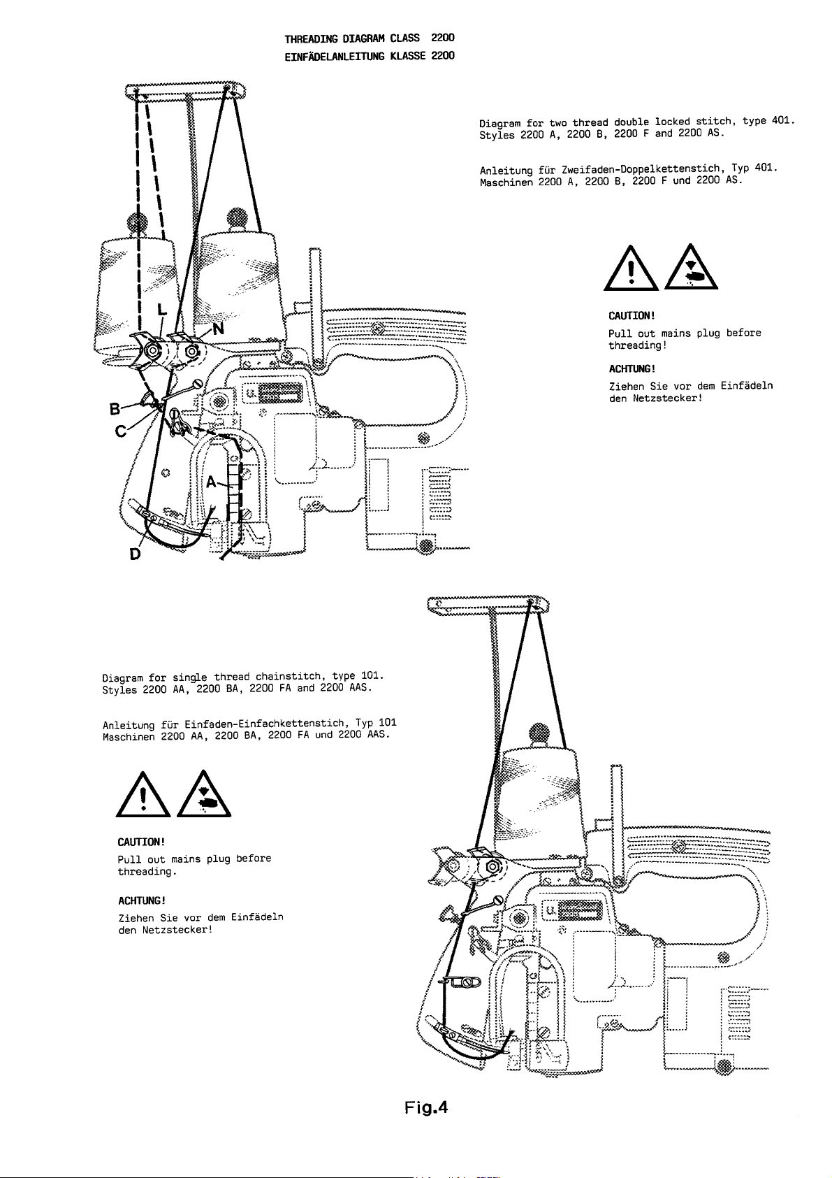
THREADING DIAGRAM CLASS 2200 11
EINFÄDELANLEITUNG KLASSE 2200
CHANGING THE NEEDLE 12
AUSWECHSELN DER NADEL
MAINTENANCE 12 - 13
WARTUNG
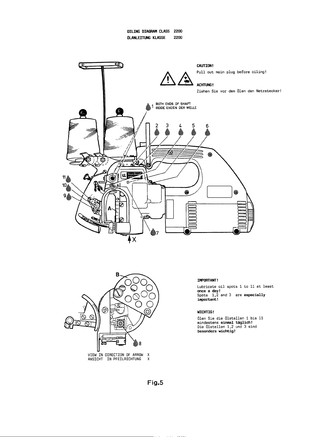
OILING DIAGRAM CLASS 2200 13
ÖLANLEITUNG KLASSE 2200
INSTRUCTIONS FOR MECHANICS 14 - 16
MECHANIKERANLEITUNG
DISASSEMBLING AND ASSEMBLING THE MOTOR 16
ABBAU UND ANBAU DES MOTORS
ORDERING WEAR AND SPARE PARTS 17
BESTELLUNG VON VERSCHLEISS- UND ERSATZTEILEN
EXPLODED VIEWS AND DESCRIPTION OF PARTS 18 - 25
EXPLOSIONSZEICHNUNGEN UND BESCHREIBUNG DER TEILE
HOUSING ASSEMBLY, BUSHINGS FOR LOOPER SHAFT, MOUNTING INSTRUCTIONS 18 - 19
GEHÄUSE KOMPLETT, BUCHSEN FÜR GREIFERWELLE, MONTAGEHINWEISE
COVER ASSEMBLY, THREAD CONE SUPPORT, UPPER FEED DRIVE MECHANISM, 20 - 21
PRESSER FOOT LEVER, UPPER FEED DOG, PRESSER FOOT, THREAD GUIDES
ABDECKUNG KOMPLETT, GARNROLLENTRÄGER, OBERTRANSPORTANTRIEB,
DRÜCKERFUSSHEBEL, OBERTRANSPORTEUR, DRÜCKERFUSS, FADENFÜHRUNGEN
HOUSING, CRANKSHAFT, NEEDLE-, LOOPER-, FEED- AND CHAINCUTTER DRIVE 22 - 25
MECHANISM, FEED DOG, LOOPER, THROAT PLATE, COVERS
GEHÄUSE, KURBELWELLE, NADEL-, GREIFER-, TRANSPORT- UND
KETTENABSCHNEIDERANTRIEB, TRANSPORTEUR, GREIFER, STICHPLATTE, ABDECKUNGEN
TAPE FOLDER AND MECHANICAL TAPE CUTTING DEVICE 26 - 27
BANDEINFASSAPPARAT UND MECHANISCHER BANDABSCHNEIDER
BAG CLOSING MACHINES 2200AZ4015FAN AND 2200AAZ4015FAN 28 - 29
SACKZUNÄHMASCHINEN 2200AZ4015FAN UND 2200AAZ4015FAN
MOTOR ASSEMBLIES 30 - 41
MOTOREN KOMPLETT
ACCESSORIES 42 - 43
ZUBEHÖR
PEDESTAL 44 - 45
PEDESTAL
TABLES FOR PEDESTAL MOUNTED STYLES 46 - 47
TISCHE FÜR PEDESTAL MONTIERTE MASCHINEN
TOP LOCK SPRING BALANCER 48
FEDERZUGAUTOSTAT
HOW TO UNRAVEL A BAG CLOSING SEAM? 49
WIE ZIEHT MAN EINE SACKZUNÄHNAHT AUF?
THREAD STAND PART NO. 93065C 50 - 51
DICHTKORDELHALTER TEIL-NR. 93065C
NUMMERICAL INDEX OF PARTS
AUF WELCHER SEITE FINDE ICH TEILE UND IHRE ABBILDUNGEN 52 - 53
3
Page 4
SAFETY RULESSAFETY RULES
SAFETY RULES
SAFETY RULESSAFETY RULES
SICHERHEITSHINWEISESICHERHEITSHINWEISE
SICHERHEITSHINWEISE
SICHERHEITSHINWEISESICHERHEITSHINWEISE
General operating instructionsGeneral operating instructions
General operating instructions
General operating instructionsGeneral operating instructions
1. Before putting the machines described in this manual
into service, carefully read the instructions. The
starting of each machine is only permitted after
taking notice of the instructions and by qualified
operators.
2. Observe the national safety rules valid for your
country.
3. Each machine is only allowed to be used as foreseen.
The foreseen use of the particular machine is
described in paragraph "MACHINE DESCRIPTION" of
this instruction manual. Another use, going beyond
the description, is not as foreseen.
4. All safety devices must be in position when the
machine is ready for work or in operation. Operation
of the machine without the appertaining safety
devices is prohibited.
5. Wear safety glasses.
6. In case of machine conversions and changes all
valid safety rules must be considered. Conversions
and changes are made at your own risk.
Allgemeine Hinweise für die BedienungAllgemeine Hinweise für die Bedienung
Allgemeine Hinweise für die Bedienung
Allgemeine Hinweise für die BedienungAllgemeine Hinweise für die Bedienung
1. Lesen Sie vor Inbetriebnahme der in diesem Katalog
beschriebenen Maschinen die Betriebsanleitung
sorgfältig. Jede Maschine darf erst nach Kenntnisnahme der Betriebsanleitung und nur durch
entsprechend unterwiesene Bedienungspersonen
betätigt werden.
2. Beachten Sie die für Ihr Land geltenden nationalen
Unfallverhütungsvorschriften.
3. Jede Maschine darf nur ihrer Bestimmung gemäß
verwendet werden. Der bestimmungsgemäße Gebrauch der einzelnen Maschine ist im Abschnitt
"MASCHINENBESCHREIBUNG" der Betriebsanleitung
beschrieben. Eine andere, darüber hinausgehende
Benutzung ist nicht bestimmungsgemäß.
4. Bei betriebsbereiter oder in Betrieb befindlicher
Maschine müssen alle Schutzeinrichtungen montiert
sein. Ohne zugehörige Schutzeinrichtungen ist der
Betrieb nicht erlaubt.
5. Tragen Sie eine Schutzbrille.
6. Umbauten und Veränderungen der Maschinen
dürfen nur unter Beachtung der gültigen Sicherheitsvorschriften vorgenommen werden. Umbauten und
Veränderungen erfolgen auf eigene Verantwortung.
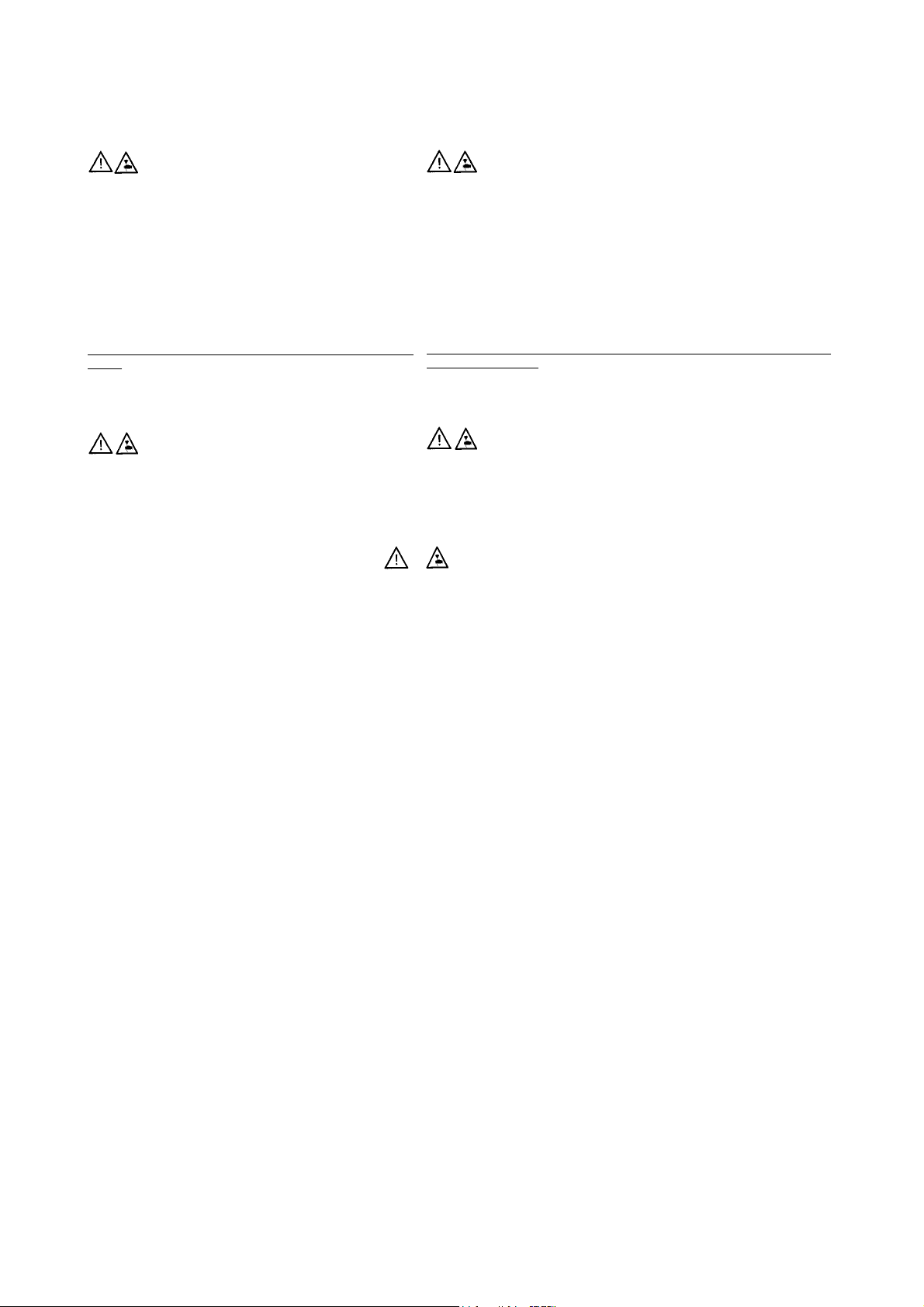
7. The warning hints in the instructions are marked
with one of these two symbols.
Special operating instructionsSpecial operating instructions
Special operating instructions
Special operating instructionsSpecial operating instructions
8. When doing the following the machine has to
be disconnected from the power supply by
pulling out the main plug.
8.1 When threading needle and looper.
8.2 When replacing any parts such as
needle presser foot, throat plate,
looper, spreader, feed dog, needle guard,
folder, fabric guide etc.
8.3 When leaving the workplace and when
the work place is unattended.
8.4 When doing maintenance work.
7. Überall da, wo die Betriebsanleitung Warnhinweise
enthält, sind diese durch eines der beiden Symbole
gekennzeichnet.
Besondere Hinweise für die BedienungBesondere Hinweise für die Bedienung
Besondere Hinweise für die Bedienung
Besondere Hinweise für die BedienungBesondere Hinweise für die Bedienung
8. Bei folgendem ist die Maschine durch Herausziehen
des Netzsteckers vom Netz zu trennen:
8.1 Zum Einfädeln von Nadel und Greifer.
8.2 Zum Auswechseln von Nähwerkzeugen, wie
Nadel, Drückerfuß, Stichplatte, Greifer,
Transporteur, Nadelanschlag, Apparat, Nähgutführung usw.
8.3 Beim Verlassen des Arbeitsplatzes und bei
unbeaufsichtigtem Arbeitsplatz.
8.4 Für Wartungsarbeiten.
4
Page 5

General maintenance directionsGeneral maintenance directions
General maintenance directions
General maintenance directionsGeneral maintenance directions
Allgemeine Hinweise für die WartungAllgemeine Hinweise für die Wartung
Allgemeine Hinweise für die Wartung
Allgemeine Hinweise für die WartungAllgemeine Hinweise für die Wartung
9. Maintenance, repair and conversion work (see
item 8) must be done only by trained technicians
or special skilled personnel under consideration of
the instructions.
Only genuine spare parts approved by UNION
SPECIAL have to be used for repairs. These parts
are designed specifically for your machine and
manufactured with utmost precision to assure
long lasting service.
10. Any work on the electrical equipment must be
done by an electrician or under direction and
supervision of special skilled personnel.
Special maintenance directionsSpecial maintenance directions
Special maintenance directions
Special maintenance directionsSpecial maintenance directions
11. Work on parts and equipment under electrical
power is not permitted. Permissible exceptions
are described in the applicable section of
standard sheet EN 50 110 / VDE 0105.
12. Before doing maintenance and repair work on
the pneumatic equipment, the machine has to
be disconnected from the compressed air supply.
In case of existing residual air pressure after
disconnecting from compressed air supply (e.g.
pneumatic equipment with air tank), the pressure
has to be removed by bleeding. Exceptions are
only allowed for adjusting work and function
checks done by special skilled personnel.
9. Wartungs-, Reparatur- und Umbauarbeiten (siehe
Punkt 8) dürfen nur von Fachkräften oder entsprechend unterwiesenen Personen unter Beachtung der Betriebsanleitung durchgeführt werden.
Für Reparaturen sind nur die von UNION
SPECIAL freigegebenen Original-Ersatzteile zu
verwenden. Diese Teile sind speziell für Ihre
Maschine konstruiert und mit der höchsten
Präzision für eine lange Lebensdauer gefertigt.
10. Arbeiten an der elekrischen Ausrüstung dürfen
nur von Elektrofachkräften oder unter Leitung
und Aufsicht von entsprechend unterwiesenen
Personen durchgeführt werden.
Besondere Hinweise für WartungBesondere Hinweise für Wartung
Besondere Hinweise für Wartung
Besondere Hinweise für WartungBesondere Hinweise für Wartung
11. Arbeiten an unter Spannung stehenden Teilen
und Einrichtungen sind nicht erlaubt. Ausnahmen
regeln die zutreffenden Teile der EN 50 110 / VDE
0105.
12. Vor Wartungs- und Reparaturarbeiten an pneumatischen Einrichtungen ist die Maschine vom
pneumatischen Versorgungsnetz zu trennen.
Wenn nach der Trennung vom pneumatischen
Versorgungsnetz noch Restenergie ansteht (z. B.
bei pneumatischen Einrichtungen mit Windkessel),
ist diese durch Entlüften abzubauen. Ausnahmen
sind nur bei Einstellarbeiten und Funktionsprüfungen durch entsprechend unterwiesene
Fachkräfte zulässig.
IDENTIFICAIDENTIFICA
IDENTIFICA
IDENTIFICAIDENTIFICA
Each UNION SPECIAL machine is identified by a
style number, which is stamped into the style plate
affixed to the machine. The serial number is fixed
into the casting of the machine housing.
TION OF MACHINESTION OF MACHINES
TION OF MACHINES
TION OF MACHINESTION OF MACHINES
BEZEICHNUNG DER MASCHINENBEZEICHNUNG DER MASCHINEN
BEZEICHNUNG DER MASCHINEN
BEZEICHNUNG DER MASCHINENBEZEICHNUNG DER MASCHINEN
Jede UNION SPECIAL Maschine hat eine Typennummer, die in das an der Maschine befestigte
Typenschild eingeprägt ist. Die Seriennummer ist in
den Guß eingelassen.
5
Page 6

MACHINE DESCRIPTIONMACHINE DESCRIPTION
MACHINE DESCRIPTION
MACHINE DESCRIPTIONMACHINE DESCRIPTION
MASCHINENBESCHREIBUNGMASCHINENBESCHREIBUNG
MASCHINENBESCHREIBUNG
MASCHINENBESCHREIBUNGMASCHINENBESCHREIBUNG
Portable bag closing machine with inegral electric motor
and built-in thread chain cutter.
For closing filled bags and sacks as well as for stitching
webs, made of jute, burlap, cotton, linen, paper, plastic,
woven polyproylene, non-wovens or combinations of
these fabrics with single thread chainstitch (stitch type
101*) or two thread double locked stitch (stitch type
401*).
Combined upper and lower feed.
Direct drive with an electric motor.
Motor ball bearing dust proof and permanently
lubricated. Heavy-duty, automatic shut-off commutator
brushes prevent damages of the armature. Motor
housing and handle made of fiberglass-reinforced breakresistant plyamide. The design of the motor housing
allows to securely put down the machine in a handy
position, when not in use.
The machines are designed for switch actuated
operation (S3 : 40%) ! A normal sewing cycle lasts approx.
5 to 8 seconds. Per hour normally up to 200 bag can be
closed.
SPECIFICASPECIFICA
SPECIFICA
SPECIFICASPECIFICA
Seam specification: 101 SSa-1 or 401 SSa-1.
Sewing capacity: up to 9 mm (3/8") or up to 24
Stitch range: 3 to 9 mm (3 to 8 1/2 SPI)
Standard Setting: 8 mm (3 SPI)
Feed: Upper and lower feed.
Teeth cut: 2.1 mm (12 teeth per inch)
Standard needle: 9854G200/080
Speed: 1200 to 1700 stitches per
TIONSTIONS
TIONS
TIONSTIONS
plies of paper.
(also refer to paragraph
"NEEDLES").
minute, depending on bag
fabric.
Tragbare Sackzunähmaschinen mit angebautem Elektromotor
und eingebautem Fadenkettenabschneider.
Zum Zunähen von gefüllten Säcken und Beuteln, sowie zum Zusammennähen von Warenbahnen, aus Jute, Baumwolle, Leinen,
Papier, Kunststoff, Polypropylengewebe, Faservlies oder aus Kombinationen dieser Materialien mit Einfaden-Einfachkettenstich
(Nähstichtyp 101*) oder Zweifaden-Doppelkettenstich
(Nähstichtyp 401*).
Kombinierter oberer und unterer Transport.
Direktantrieb durch Elektromotor.
Motorkugellager staugeschützt und auf Lebensdauer geschmiert.
Abschaltkohlen mit hoher Standzeit verhindern Ankerbeschädigungen.
Motorgehäuse und Handgriff aus glasfaserverstärktem, bruchsicherem Polyamid. Die Konstruktion des Motorgehäuses erlaubt
es, die Maschine nach Gebrauch sicher und griffbereit hinzustellen.
Die Maschinen sind für Schaltbetrieb (S3 : 40%) ausgelegt!
Ein normaler Nähvorgang dauert ca. 5 bis 8 Sekunden; pro Stunde können normalerweise bis zu 200 Säcke verschlossen werden.
DADA
TENTEN
DA
TEN
DADA
TENTEN
Nahtbild: 101 SSa-1 oder 401 SSa-1.
Nähkapazität: bis 9 mm oder bis zu 24 Lagen Papier.
Stichlänge: 3 bis 9 mm
Standardeinstellung: 8 mm.
Transport: Ober- und Untertransport
Zahnteilung: 2,1 mm
Standardnadel: 9854G200/080
Drehzahl: 1200 bis 1700 Stiche/min., je nach Sack-
(siehe auch Abschnitt "NADELN")
material.
Sound pressure level at recommended operating speed
(1500 rpm): 79 dB (A), measurement acc. to DIN 45635-48.
Weighted root mean square acceleration value at
recommended operating speed (1500 rpm): <2.5m/s2,
measurement according to ISO 8662-1 / EN 28662 and ISO
5349.
Power cable: 5 meters long (approx. 16 ft.)
Weight: 5 kg (11 lbs.) (approx.)
SPECIFICASPECIFICA
SPECIFICA
SPECIFICASPECIFICA
single-phase commutator motor
Frequency range: 50/60 Hz
Power: 0.12 kW (input)
Duty cycle: S3: 40 % according to ISO 34-1.
Speed of motor (no-load operation): approx. 9000 rpm
Insulation class B.
Voltages and protection classes:
°220 to 240 V protection class I**, with ground wire
°220 to 240 V protection class II**, reinforced insulation
°110 to 125 V protection class I**, with ground wire
°42 V protection class III**, safety extra-low
24 V DC protection class III**, safety extra-low
12 V DC protection class III**, safety extra-low
TIONSTIONS
TIONS
(electric drive)
TIONSTIONS
The relative duty cycle should
not exceed a period of 40 %,
relating to a cycle of 10
minutes.
without ground wire
voltage
voltage
voltage
Arbeitsplatzbezogener Emmissionswert bei empfohlener Betriebsdrehzahl (1500 Stiche/min.): 79 dB (A), Messung nach DIN 45635-
48.
Gewichteter Effektivwert der Beschleunigung bei empfohlener
Betriebsdrehzahl (1500 Stiche/min.): < 2,5 m/s2,
Messung nach ISO 8662-1 / EN 28662 und ISO 5349.
Anschlußkabel: 5 m lang.
Gewicht: 5 kg (ca.)
DADA
TENTEN
DA
TEN
(Elektroantrieb)
DADA
TENTEN
Einphasen-Wechselstrom-Kommutatormotor
Frequenzbereich: 50/60 Hz
Leistung: 0.12 kW (Aufnahme)
Betriebsart: S3: 40% nach ISO 34-1/DIN VDE 0530.
Drehzahl des Motors (Leerlauf): etwa 9000 U/min.
Isolierstoffklasse B.
Spannungsbereiche und Schutzklassen:
°220 bis 240 V Schutzklasse I**, mit Schutzleiter
°220 bis 240 V Schutzklasse II**, schutzisoliert ohne Schutzleiter
°110 bis 125 V Schutzklasse I**, mit Schutzleiter
° 42 V Schutzklasse III**, Sicherheitskleinspannung
24 V DC Schutzklasse III**, Sicherheitskleinspannung
12 V DC Schutzklasse III*, Sicherheitskleinstpannung
Die relative Einschaltdauer darf einen
Zeitraum von 40%, bezogen auf einen
Zyklus von 10 Minuten, nicht überschreiten.
° These motors are equipped with commutator brushes
which automatically cut off the circuit in case of wearing
out (approx. 500 working hours). This prevents damage
of the armature and can only be assured when using
genuine Union Special commutator brushes and spare
parts.
* According to ISO 4915
** According to the regulations for electrical
tools IEC 745-1, EN 50144.
NOTE: Protection class II is subject of authorisation in
some countries.
° Diese Motoren sind mit Kohlebürsten ausgerüstet, die sich nach
Abnutzung (ca. 500 Betriebsstunden) selbsttätig abschalten.
Dies verhindert Beschädigungen des Ankers und ist nur gewährleistet, wenn Union Special Ersatz-Kohlebürsten und Teile
verwendet werden.
* Nach ISO 4915
** Entsprechend den Bestimmung für Elektrowerkzeuge
IEC 745-1, EN 50144.
BEACHTEN SIE: Schutzklasse II ist in einigen Ländern genehmigungspflichtig.
6
Page 7

STYLES OF MACHINESSTYLES OF MACHINES
STYLES OF MACHINES
STYLES OF MACHINESSTYLES OF MACHINES
MACHINENTYPENMACHINENTYPEN
MACHINENTYPEN
MACHINENTYPENMACHINENTYPEN
2200A 2200A
2200A Double locked stitch, stitch type 401.
2200A 2200A
Motor for 220 to 240 V, 50/60 Hz.
Protection class I, with ground wire.
2200AE 2200AE
2200AE Same as 2200A but designed for II 3 D T125°C,
2200AE 2200AE
non-conductive dust; ATEX Directive 94/9/EC.
2200B 2200B
2200B Double locked stitch, stitch type 401.
2200B 2200B
Motor for 110 to 125 V, 50/60 Hz.
Protection class I, with ground wire.
2200F 2200F
2200F Double locked stitch, stitch type 401.
2200F 2200F
Motor for 42 V, 50/60 Hz.
Protection class III, safety extra-low voltage.
2200M 2200M
2200M Double locked stitch, stitch type 401.
2200M 2200M
Motor for 12 V DC.
Protection class III, safety extra-low voltage.
2200AS 2200AS
2200AS Double locked stitch, stitch type 401.
2200AS 2200AS
Motor for 200 to 240 V, 50/60 Hz.
Protection class II, without ground wire.
2200AA 2200AA
2200AA Single thread chainstitch, stitch type 101.
2200AA 2200AA
Motor for 220 to 240 V, 50/60 Hz.
Protection class I, with ground wire.
2200AAE 2200AAE
2200AAE Same as 2200AA, but designed for II 3 D T125°C,
2200AAE 2200AAE
non-conductive dust; ATEX Directive 94/9/EC.
2200BA 2200BA
2200BA Single thread chainstitch, stitch type 101.
2200BA 2200BA
Motor for 110 to 125 V, 50/60 Hz.
Protection class I, with ground wire.
2200A 2200A
2200A Doppelkettenstich, Nähstichtyp 401.
2200A 2200A
Motor für 220 bis 240 V, 50/60 Hz.
Schutzklasse I. mit Schutzleiter.
2200AE2200AE
2200AE Wie 2200A, jedoch ausgelegt für II 3 D T125°C,
2200AE2200AE
nichtleitende Stäube; ATEX-Richtlinie 94/9/EG.
2200B 2200B
2200B Doppelkettenstich, Nähstichtyp 401.
2200B 2200B
Motor für 110 bis 125 V, 50/60 Hz.
Schutzklasse I, mit Schutzleiter.
2200F 2200F
2200F Doppelkettenstich, Nähstichtyp 401.
2200F 2200F
Motor für 42 V, 50/60 Hz.
Schutzklasse III, Sicherheitskleinspannung.
2200M 2200M
2200M Doppelkettenstich, Nähstichtyp 401.
2200M 2200M
Motor für 12 V DC.
Schutzklasse III, Sicherheitskleinspannung.
2200AS 2200AS
2200AS Doppelkettenstich, Nähstichtyp 401.
2200AS 2200AS
Motor für 220 bis 240 V, 50/60 Hz.
Schutzklasse II, ohne Schutzleiter.
2200AA 2200AA
2200AA Einfachkettenstich, Nähstichtyp 101.
2200AA 2200AA
Motor für 220 bis 240 V, 50/60 Hz.
Schutzklasse I, mit Schutzleiter.
2200AAE 2200AAE
2200AAE Wie 2200AA, jedoch ausgelegt für II 3 D T125°C,
2200AAE 2200AAE
nichtleitende Stäube; ATEX-Richtlinie 94/9/EG.
2200BA 2200BA
2200BA Einfachkettenstich, Nähstichtyp 101.
2200BA 2200BA
Motor für 110 bis 125 V, 50/60 Hz.
Schutzklasse I, mit Schutzleiter.
2200F2200F
A A
2200F
A Single thread chainstitch, stitch type 101.
2200F2200F
A A
Motor for 42 V, 50/60 Hz.
Protection class III, safety extra-low voltage.
2200MA 2200MA
2200MA Single thread chainstitch, stitch type 101.
2200MA 2200MA
Motor for 12 V DC.
Protection class III, safety extra-low voltage.
2200AAS 2200AAS
2200AAS Single thread chainstitch, stitch type 101.
2200AAS 2200AAS
Motor for 220 to 240 V, 50/60 Hz.
Protection class II, without ground wire.
2200MB 2200MB
2200MB Double locked stitch, stitch type 401.
2200MB 2200MB
Motor for 24 V DC. Protection class III, safety extra-low
voltage, using four longlife, rechargeable
NC-batteries which are integrated in a leather belt.
Battery charger primary 230 V, 50 Hz included.
Available extras:
Additional battery belt Part No. 90195
Additional battery charger Part No. 90195B
2200MAB 2200MAB
2200MAB Same as 2200MB, but single thread chainstitch,
2200MAB 2200MAB
stitch type 101.
2200AZ4015F2200AZ4015F
2200AZ4015F
2200AZ4015F2200AZ4015F
Without motor, for bag closing units.
Speed: up to 1500 stitches per minute.
2200AAZ4015F2200AAZ4015F
2200AAZ4015F
2200AAZ4015F2200AAZ4015F
Without motor, for bag closing units.
Speed: up to 1500 stitches per minute.
AN AN
AN Double locked stitch, stitch type 401.
AN AN
AN AN
AN Single thread chainstitch, stitch type 101.
AN AN
2200F2200F
A A
2200F
A Einfachkettenstich, Nähstichtyp 101.
2200F2200F
A A
Motor für 42 V, 50/60 Hz.
Schutzklasse III, Sicherheitskleinspannung.
2200MA 2200MA
2200MA Einfachkettenstich, Nähstichtyp 101.
2200MA 2200MA
Motor für 12 V DC.
Schutzklasse III, Sicherheitskleinspannung.
2200AAS 2200AAS
2200AAS Einfachkettenstich, Nähstichtyp 101.
2200AAS 2200AAS
Motor für 220 bis 240 V, 50/60 Hz.
Schutzklasse II, ohne Schutzleiter.
2200MB 2200MB
2200MB Doppelkettenstich, Nähstichtyp 401.
2200MB 2200MB
Motor für 24 V DC. Schutzklasse III, Sicherheitskleinspannung, Stromversorgung durch vier langlebige,
aufladbare, in einem Ledergürtel integrierte
NC-Batteriezellen.
Ladegerät, primär 230 V, 50 Hz, im Lieferumfang.
Zusätzlich lieferbar:
Extra Batteriegürtel Teil Nr. 90195
Extra Ladegerät Teil Nr. 90195B
2200MAB 2200MAB
2200MAB Wie 2200MB, jedoch Einfachkettenstich,
2200MAB 2200MAB
Nähstichtyp 101.
2200AZ4015F2200AZ4015F
2200AZ4015F
2200AZ4015F2200AZ4015F
Ohne Motor, für Sackzunähanlagen.
Drehzahl: max. 1500 Stiche/min.
2200AAZ4015F2200AAZ4015F
2200AAZ4015F
2200AAZ4015F2200AAZ4015F
Ohne Motor, für Sackzunähanlagen.
Drehzahl: max. 1500 Stiche/min.
AN AN
AN Doppelkettenstich, Nähstichtyp 401.
AN AN
AN AN
AN Einfachkettensitch, Nähstichtyp 101.
AN AN
For repair sewing machines without motor areFor repair sewing machines without motor are
For repair sewing machines without motor are
For repair sewing machines without motor areFor repair sewing machines without motor are
available:available:
available:
available:available:
2200AZ4015 2200AZ4015
2200AZ4015 Sewing machine only, without handle and
2200AZ4015 2200AZ4015
motor. Double locked stitch, stitch type 401.
2200AAZ4015 2200AAZ4015
2200AAZ4015 Sewing machine only, without handle and
2200AAZ4015 2200AAZ4015
motor. Single thread chainstitch, stitch type 101.
HINT:HINT:
HINT:
HINT:HINT:
Each two thread double locked stitch machine of class
2200 can be converted into a single thread chainstitch
machine and vice versa. The conversion works have to be
done only by skilled personnal under observance ot the
safety rules and under consideration of the instructions.
Für Reparaturzwecke stehen auch Nähmaschinen ohneFür Reparaturzwecke stehen auch Nähmaschinen ohne
Für Reparaturzwecke stehen auch Nähmaschinen ohne
Für Reparaturzwecke stehen auch Nähmaschinen ohneFür Reparaturzwecke stehen auch Nähmaschinen ohne
Motor zur VMotor zur V
Motor zur V
Motor zur VMotor zur V
2200AZ4015 2200AZ4015
2200AZ4015 Nähkopf allein, ohne Handgriff und Motor.
2200AZ4015 2200AZ4015
Doppelkettenstich, Nähstichtyp 401.
2200AAZ4015 2200AAZ4015
2200AAZ4015 Nähkopf allein, ohne Handgriff und Motor.
2200AAZ4015 2200AAZ4015
Einfachkettenstich, Nähstichtyp 101.
HINWEIS:HINWEIS:
HINWEIS:
HINWEIS:HINWEIS:
Jede Zweifaden-Doppelkettenstichmaschine der Klasse
2200 kann in eine Einfaden-Einfachkettenstichmaschine
umgebaut werden und umgekehrt. Die Umbauarbeiten
dürfen nur von Fachkräften unter Einhaltung der Sicherheitshinweise und unter Beachtung der Betriebsanleitung durchgeführt werden.
7
erer
fügung:fügung:
er
fügung:
erer
fügung:fügung:
Page 8
NEEDLESNEEDLES
NEEDLES
NEEDLESNEEDLES
NADELNNADELN
NADELN
NADELNNADELN
Each needle has both a type and size number. The
type number denotes the kind of shank, point, length,
groove, finish and other details. The metric size number,
stamped on the needle shank, denotes largest
diameter of blade, measured in hundreds of a mm
across the eye. Collectively, type and size number
(metric/inch) represent the complete symbol, which
is given on the label of all needles packaged and sold
by UNION SPECIAL.
The standard needle for the machines described in
this manual is 9854G200/080.
Depending on the sewing operation each machine
style can be equipped with on of the needle types
and sizes described in the following:
Type Number Description and sizes
9854G Round shank, square point, double
groove, spotted, chromium plated.
Sizes: 125/049, 170/067, 200/080, 230/090
9857T Round shank, round point, double
groove, spotted, Lo-temp finish.
Size: 200/080.
Selection of proper needle size should be determined
ba the size of the thread used. Thread should pass
freely through the needle eye in order to produce a
good stitch formation.
To have needle orders promptly and accurately fill,
an empty package, a sample needle, or the type and
size number should be forwarded.
Use description on label. A complete order would
read:
Jede Nadel hat eine Typnummer und eine Dickenbezeichnung.
Die Typnummer bezeichnet die Art des Nadelkolbens, der Spitze, Länge, Rinne, Oberfläche und andere Einzelheiten. Die metrische Dickenbezeichnung, im Nadelkolben eingeprägt, gibt
den größten Durchmesser des Nadelschaftes in hunderstel Millimeter an, gemessen am Öhr. Typnummer und Dickenbezeichnung (metrisch/inch) zusammen ergeben die vollständige Nadelbezeichnung, die auf jedem Etikett aller von UNION
SPECIAL gepackten und verkauften Nadeln steht.
Die Standardnadel für die in diesem Handbuch beschriebenen
Maschinen ist 9854G200/080.
Je nach Nähoperation kann jedoch jede Maschine mit einer
der nachfolgend beschriebenen Typnummer und Dicken ausgerüstet werden:
Typnummer Beschreibung und Dicken
9854G Rundkolben, Vierkantspitze, Doppelrinne, Hohl-
kehle, verchromt.
Dicken: 125/049, 170/067, 200/080, 230/090.
9857T Rundkolben, Rundspitze, Doppelrinne, Hohl-
kehle, Lo-temp Belag.
Dicke: 200/080.
Die Wahl der Nadeldicke richtet sich nach dem verwendeten
Nähfaden. Der Faden muß frei durch das Nadelöhr gleiten um
eine gute Stichbildung zu gewährleisten.
Um Nadelbestellung richtig und prompt ausführen zu können,
senden Sie bitte eine leere Nadelpackung oder eine Musternadel ein, oder geben Sie Typnummer und Dicke an. Benützen
Sie dazu die Beschreibung auf dem Etikett der Nadelpackung.
Eine vollständige Bestellung würde z. B. lauten:
100 Needles, Type 9854G200/080.
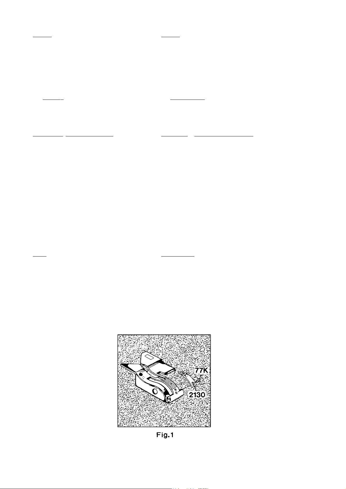
NOTE: In case the bag fabric is extremely thin, it is
recommended to use needle size 125/049 or 170/067
in combination with throat plate needle hole section
part No. 2130* and screw part No. 77K*, (see Fig. 1).
Recommended sewing thread size for these needle
sizes is Ne 34/4.
When exclusively closing plastic bags it is
recommended to use needle type 9587T200/080 with
round point and Lo-temp finish.
Depending on the thickness of the plastic foil or fabric,
it is recommended to additionally use the throat plate
needle hole section No. 2130* and screw No. 77K*.
100 Nadeln Typ 9854G200/080.
BEACHTEN SIE:
fohlen, die Nadeldicke 125/049 oder 170/067 zusammen mit der
Stichlochauflage Teil Nr. 2130* und Schraube Teil Nr. 77K* zu verwenden (siehe Fig. 1).
Die empfohlene Nähgarnstärke für diese Nadeldicken ist
Ne 34/4.
Werden ausschließlich Kunststoffsäcke verschlossen, wird
empfohlen, den Nadeltyp 9857T200/080 mit Rundspitze und Lotemp Belag zu verwenden.
Abhängig von der Dicke der Kunststofffolie oder des Stoffes wird
empfohlen, zusätzlich die Stichlochauflage Nr. 2130* und die
Schraube Nr. 77K* zu verwenden.
Bei besonders dünnen Sackstoffen wird emp-
* Extra order and charge item.
* Gegen zusätzliche Bestellung und Berechnung.
8
Page 9
OPERAOPERA
TING INSTRUCTIONSTING INSTRUCTIONS
OPERA
TING INSTRUCTIONS
OPERAOPERA
TING INSTRUCTIONSTING INSTRUCTIONS
BEDIENUNGSANLEITUNGBEDIENUNGSANLEITUNG
BEDIENUNGSANLEITUNG
BEDIENUNGSANLEITUNGBEDIENUNGSANLEITUNG
PUTTING INTO SERPUTTING INTO SER
PUTTING INTO SER
PUTTING INTO SERPUTTING INTO SER
Before leaving our factory each machine is carefully
inspected, adjusted and given a sewing test. However,
upen receipt the machine should be inspected and
any damage or complaint should be reported to Union Special or their distributor without delay.
Unpack the machine. Make sure that no pieces of
packing are trapped in the mechanism.
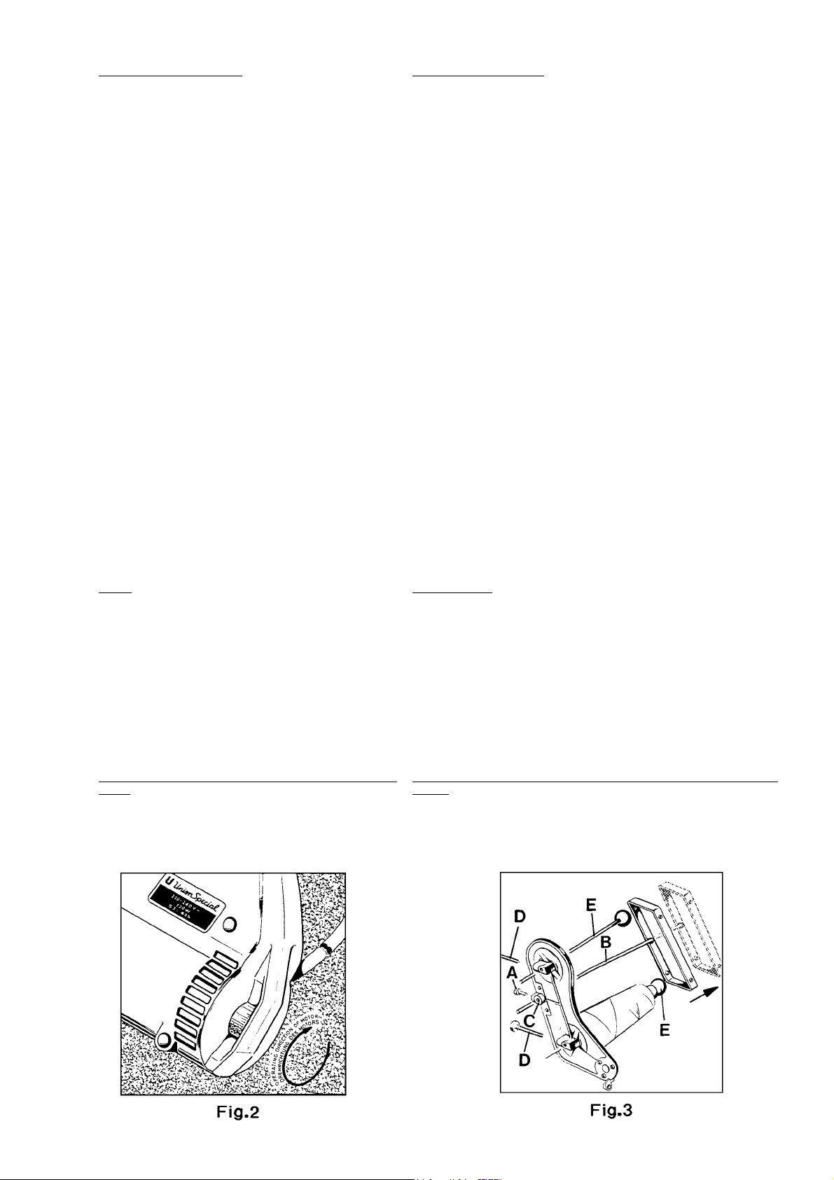
Check by turning the motor handwheel in operating
direction (see Fig. 2) if the machine works. A slight
restistance will be felt as the feed dog rises.
Loosen screw (A, Fig. 3) and set thread rod (B) so that
its lower end is flush with the underside of thread cone
support (C). Retighten screw (A).
Check the threading of the machine. Observe the
threading diagram Fig. 4 and paragraph "THREADING".
Lubricate the machine again as per oiling diagram Fig.
5.
Depending upon the operating conditions, oiling
should be done at least once a day.
Check if the voltage of the sewing motor corresponds
with the voltage of the wall socket. Wall sockets for
machines with ground wire must be porperly grounded.
Insert the plug of the power cable into the wall socket.
Start stitching on a piece of the bag material (jute,
paper, polypropylene etc) by pressing the thumb
switch. Continue stitching as the bag leaves the
machine. This will produce a thread chain, which when
guided into the V-cut out of the throat plate is
automatically cut by the thread chain cutting knives.
Release the switch, the machine stops.
VICEVICE
VICE
VICEVICE
INBETRIEBNAHMEINBETRIEBNAHME
INBETRIEBNAHME
INBETRIEBNAHMEINBETRIEBNAHME
Vor Verlassen unseres Werkes wurde jede Maschine sorgfältig geprüft, eingestellt und ein Nähtest durchgeführt. Jedoch soll bei Erhalt die Maschine überprüft werden und jede Beschädigung oder
Beanstandung umgehend an Union Special oder deren Vertreter
gemeldet werden.
Packen Sie die Maschine aus. Überzeugen Sie sich, daß sich kein
Verpackungsmaterial im Mechanismus verfangen hat.
Prüfen Sie durch Drehen des Motor-Handrades in Drehrichtung (siehe Fig. 2), ob die Maschine arbeitet. Beim Hochgehen des Transporteurs wird ein leichter Widerstand spürbar.
Lösen Sie die Schraube (A, Fig. 3), und stellen Sie die Fadenstange
(B) so, daß ihr unteres Ende mit der Unterseite des Garnrollenträgers
(C) bündig ist. Ziehen Sie die Schraube (A) wieder an.
Prüfen Sie die Einfädelung der Maschine. Beachten Sie die Einfädelanleitung Fig. 4 und den Abschnitt "EINFÄDELN".
Ölen Sie die Maschine nochmals, entsprechend der Ölanleitung
Fig. 5.
Abhängig von den Betriebsbedingungen muß täglich mindestens
einmal geölt werden.
Prüfen Sie, ob die Spannung des Nähmotors mit der Spannung an
der Steckdose übereinstimmt. Steckdosen für Maschinen mit Schutzleiter müssen korrekt geerdet sein.
Stecken Sie den Stecker des Anschlußkabels in der Steckdose ein.
Beginnen Sie auf einem Stück Sackmaterial (Jute, Papier, Polypropylen usw.) zu nähen, indem Sie den Druckknopfschalter betätigen. Nähen Sie weiter, nachdem die Maschine das Sackmaterial
verlassen hat. Dabei wird eine Fadenkette gebildet, die, wenn sie
in den V-förmigen Ausschnitt der Stichplatte geführt wird, automatisch von den Fadenkettenabschneidmessern abgeschnitten wird.
Lassen Sie den Schalter los; die Maschine stoppt.
NOTE: The knives only function when the machine is
operating. Otherwise the thread chain will break when
pulled and could cause damage to the needle and
looper.
OPERAOPERA
TINGTING
OPERA
TING
OPERAOPERA
TINGTING
The machines are designed for switch-actuated
operation. A normal sewing cycle lasts approx. 5 to 8
seconds. Depending on bag width and material as
well as the operation conditions at site approx 200 250 bags can be closed per hour.
For a neat, presentable closure the filled bag has to
be prepared as follows:
Paper, heavy gauge plastic, coated polypropylene
bags:
Insert both hands into the opening of the filled bag
and spread it apart. Then grip both outer edges of
the bag and fold with a sharp movement the bag
top forward and over to expel the air.
BEACHTEN SIE: Die Messer arbeiten nur, wenn die Maschine läuft;
sonst reißt die Fadenkette, wenn gezogen wird. Dabei können die
Nadel und der Greifer beschädigt werden.
BEDIENENBEDIENEN
BEDIENEN
BEDIENENBEDIENEN
Die Maschinen sind für Schaltbetrieb ausgelegt. Ein normaler
Nähvorgang dauert ca. 5 bis 8 Sekunden. Je nach Sackbreite
und Material sowie den örtlichen Bedingungen können ca. 200
bis 250 Säcke pro Stunde zugenäht werden.
Für einen sauberen, vorzeigbaren Verschluß muß der gefüllte Sack
wie folgt vorbereitet werden:
Papier-, schwere Kunststofffoliensäcke, beschichtete Polypropylensäcke:
Stecken Sie beide Hände in die Öffnung des gefüllten Sackes und
spreizen Sie ihn auseinander. Greifen Sie nun die beiden Außenkanten des Sackes und falten Sie die Sackoberseite mit einer
schnellen Bewegung nach vorne über, damit die Luft entweicht.
9
Page 10
Bring the bag top to the upright position so that it is
flat and vertical.
Bring the machine to the right hand side of the bag,
approx. 25 to 40 mm (1- 1 1/2") from the top.
Enter the leading edge of the bag between presser
foot and throat plate.
Keep a security distance of approx. 100 mm
(4") between main and sewing needle!
Richten Sie die Sackoberseite wieder auf, so daß sie flach und senkrecht ist.
Bringen Sie die Maschine an die rechte Seite des Sackes etwa 25
bis 40 mm von der Oberkante.
Führen Sie die Sackvorderkante zwischen Drückerfuß und Stichplatte.
Halten Sie einen Sicherheitsabstand von ca. 100 mm
zwischen Hand und Nähnadel ein!
Press the thumb switch. The machine sews across the
bag, requiring the operator only to keep pace by
moving the hand in conjunction with the sewing speed
of the machine.
As the machine comes off the bag guide the thread
chain with a slight twist of the rist into the knives,
simultaneously release the switch.
The machine stops.
This results in a short, neat thread chain at the
beginning and end of the bag.
Hessian, jute, woven polypropylene, cotton and net
bags:
These bag materials ar not stiff enough, therefore the
right leading edge of the bag has to be entered with
the left hand into the machine.
Keep a security distance of approx. 100 mm
(4") between main and sewing needle!
While sewing the operator should move the left hand
to the left side of the bag, maintaining a slight tension
across the top of the bag.
THREADINGTHREADING
THREADING
THREADINGTHREADING
Pull out mains plug before threading!
Loosen thumb screw(s) (D, Fig. 3) in the thread cone
support, pull out the spool pin(s) (E) and remove the
empty thread cone(s).
Insert the new thread cone(s) with spool pin(s) (E) and
retighten thumb screw(s) (D).
Betätigen Sie den Druckknopfschalter. Die Maschine näht quer über
den Sack. Dabei brauch die Bedienungsperson ihre Handbewegung nur an die Geschwindigkeit der Maschine anzupassen.
Wenn die Maschine den Sack verläßt, führen Sie mit einer leichten
Drehung des Handgelenks die Fadenkette in die Messer und lassen gleichzeitig den Schalter los.
Die Maschine stoppt.
Dies ergibt eine kurze, saubere Fadenkette am Anfang und Ende
des Sackes.
Säcke aus Sackleinwand, Jute, Polypropylengewebe, Baumwolle
und Netzgewebe:
Diese Sackmaterialien sind nicht steif genug, deshalb muß die rechte
Sackvorderkante mit der linken Hand in die Maschine geführt werden.
Halten Sie einen Sicherheitsabstand von ca. 100 mm
zwischen Hand und Nähnadel ein!
Während des Nähens soll die Bedienungsperson ihre linke Hand zur
linken Seite des Sackes bewegen und eine leichte Spannung auf
die Sackoberkante ausüben.
EINFEINF
ÄDELNÄDELN
EINF
ÄDELN
EINFEINF
ÄDELNÄDELN
Ziehen Sie vor dem Einfädeln den Netzstecker!
Lösen Sie die Rändelschraube(n) (D, Fig. 3) im Garnrollenträger, ziehen Sie den (die) Spulenstift(e) heraus und entfernen Sie die leere(n)
Garnrolle(n).
Setzen Sie die neue(n) Garnrolle(n) mit dem (den) Spulenstift(en)
(E) ein und ziehen Sie die Rändelschraube(n) wieder an.
Thread the machine as shown in Fig. 4.
For threading the needle, turn motor handwheel in
operating direction until the needle is in its upmost
position above the throat plate.
For threading the looper (double locked stitch
machines only) open the hinged cover (A, Fig. 4) and
turn motor handwheel in operating direction until the
needle is in its lowest position below the throat plate.
Reclose hinged cover (A) after threading.
THREAD TENSIONTHREAD TENSION
THREAD TENSION
THREAD TENSIONTHREAD TENSION
The tension (L, Figs. 4 and 13) controls the looper thread
and the tension (N) controls the needle thread.Only a
slight tension should be applied on the looper thread.
The tension applied on the needle thread depends
upon the size of the thread and the thickness of the
fabric to be sewn and has to be regulated till the
machine sews and chains off perfectly.
PRESSER FOOT PRESSUREPRESSER FOOT PRESSURE
PRESSER FOOT PRESSURE
PRESSER FOOT PRESSUREPRESSER FOOT PRESSURE
The pressure on the presser foot should be just so strong
that the machine feeds uniformly on the fabric to be
sewn. When leaving the fabric to be sewn, an uniform
thread chain must be formed.
The presser foot pressure is regulated with the knurled
regulating screw (B, Fig. 4).
For adjustment loosen nut (C) and turn the regulating
screw (B) clockwise to increase the pressure or
counterclockwise to decrease the pressure.
Fädeln Sie die Maschine wie in Fig. 4 gezeigt ein.
Zum Einfädeln der Nadel drehen Sie am Motor-Handrad in Drehrichtung bis die Nadel in der höchsten Stellung über der Stichplatte
ist.
Zum Einfädeln des Greifers (nur bei Doppelkettenstichmaschinen)
öffnen Sie die Verschlußklappe (A, Fig. 4) und drehen am MotorHandrad in Drehrichtung bis die Nadel in der tiefsten Stellung unter
der Stichplatte ist.
Schließen Sie nach dem Einfädeln die Verschlußklappe (A) wieder.
FF
ADENSPADENSP
F
ADENSP
FF
ADENSPADENSP
Die Spannung (L, Fig. 4 und 13) reguliert den Greiferfaden und die
Spannung (N) den Nadelfaden.
Der Greiferfaden soll nur leicht gespannt sein.
Die Nadelfadenspannung wird je nach Stärke des Fadens und der
Dicke des Nähgutes einreguliert, so daß die Maschine einwandfrei
näht und kettelt.
DRÜCKERFUSSDRUCKDRÜCKERFUSSDRUCK
DRÜCKERFUSSDRUCK
DRÜCKERFUSSDRUCKDRÜCKERFUSSDRUCK
Der Druck auf den Drückerfuß soll gerade so stark sein, daß die
Maschine gleichmäßig auf dem Nähgut transportiert. Nach dem
Verlassen des Nähgutes muß sich eine gleichmäßige Fadenkette
bilden.
Der Drückerfußdruck wird mit der gerändelten Stellschraube (B, Fig.
4) reguliert.
Lösen Sie zum Einstellen die Mutter (C) und drehen Sie die Stellschraube (B) im Uhrzeigersinn um den Druck zu verstärken, oder im
Gegenuhrzeigersinn um ihn zu verringersn.
ANNUNGANNUNG
ANNUNG
ANNUNGANNUNG
Retighten nut (C).
Ziehen Sie die Mutter (C) wieder an.
10
Page 11
11
Page 12

CHANGING THE NEEDLECHANGING THE NEEDLE
CHANGING THE NEEDLE
CHANGING THE NEEDLECHANGING THE NEEDLE
Pull out mains plug before changing
the needle!
AUSWECHSELN DER NADELAUSWECHSELN DER NADEL
AUSWECHSELN DER NADEL
AUSWECHSELN DER NADELAUSWECHSELN DER NADEL
Ziehen Sie vor dem Auswechseln der Nadel
den Netzstecker!
Turn motor handwheel in operating direction until the
needle is in its upmost position above the throat plate.
Unthread the eye of the needle.
Loosen the screw (D, Fig. 4) for the needle and draw out
the needle. Insert the shank of the new needle as far as it
will go into the needle seat and with the flat on the shank
facing to the front.
Retighten screw (D) for the needle on the flat of the needle
shank and thread the needle eye.
MAINTENANCEMAINTENANCE
MAINTENANCE
MAINTENANCEMAINTENANCE
Pull out the mains plug before doing
maintenance work or before oiling!
OILINGOILING
OILING
OILINGOILING
The machine has to be oiled at least once a day on the oil
spots 1 to 11 shown in the oiling diagram Fig. 5.
Oil spots 1, 2 and 3 are especially important!
Recommended oil: Mobil D.T.E., Oil Medium.
This oil can be purchased from Union Special in 0.5 liter
containers under part No. G28604L or in 5 liter containers
under the part No. G28604L5.
CLEANINGCLEANING
CLEANING
CLEANINGCLEANING
Clean the machine at least once a week from lint. For this
also open hinged cover (A, Fig. 5) and the punched cover
(B, Fig. 5).
Reclose covers.
Drehen Sie am Motor-Handrad in Drehrichtung bis die Nadel in der höchsten Stellung über der Stichplatte ist. Fädeln
Sie das Nadelöhr aus.
Lösen Sie die Schraube (D, Fig. 4) für die Nadel und ziehen
Sie die Nadel heraus. Stecken Sie den Kolben der neuen
Nadel bis zum Anschlag in den Nadelsitz und so, daß die
Fläche am Kolben nach vorne zeigt.
Ziehen Sie die Schraube (D) für die Nadel auf der Fläche
des Nadelkolbens wieder an, und fädeln Sie das Nadelöhr
ein.
WW
ARAR
TUNGTUNG
W
AR
TUNG
WW
ARAR
TUNGTUNG
Ziehen Sie vor Wartungsarbeiten oder zum Ölen
den Netzstecker!
ÖLENÖLEN
ÖLEN
ÖLENÖLEN
Die Maschine muß täglich mindestens einmal an den in der
Ölanleitung Fig. 5 angegebenen Ölstellen 1 bis 11 geschmiert werden.
Die Ölstellen 1, 2 und 3 sind besonders wichtig!
Geeignetes Öl: Mobil D.T.E. Oil Medium.
Dieses Öl ist in 0,5 l Behältern unter der Teil-Nr. G28604L oder
in 5 l Behältern unter der Teil-Nr. G28604L5 von Union Special
erhältlich.
REINIGENREINIGEN
REINIGEN
REINIGENREINIGEN
Reinigen Sie die Maschine mindestens einmal wöchentlich
von Flusen. Öffnen Sie dazu auch die Verschlußklappe (A,
Fig. 5) und das gelochte Abschlußblech (B, Fig. 5).
Schließen Sie die Abdeckungen wieder.
12
Page 13
13
Page 14
INSTRUCTIONS FOR MECHANICSINSTRUCTIONS FOR MECHANICS
INSTRUCTIONS FOR MECHANICS
INSTRUCTIONS FOR MECHANICSINSTRUCTIONS FOR MECHANICS
MECHANIKERANLEITUNGMECHANIKERANLEITUNG
MECHANIKERANLEITUNG
MECHANIKERANLEITUNGMECHANIKERANLEITUNG
Observe the
SETTING THE LOOPERSETTING THE LOOPER
SETTING THE LOOPER
SETTING THE LOOPERSETTING THE LOOPER
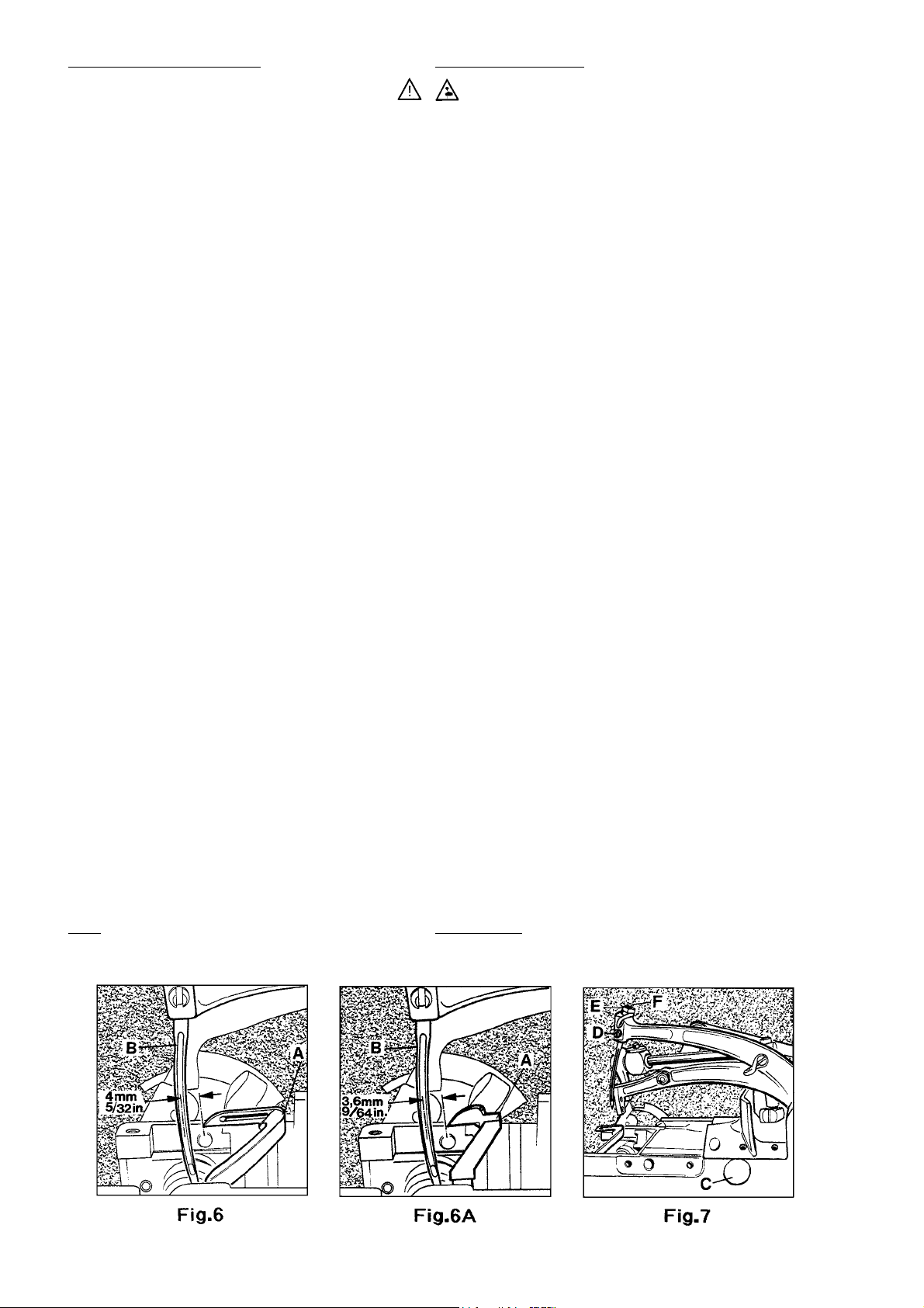
1. Looper for two thread double locked stitch:
Set the looper (A, Fig. 6) so that the distance from the center
of the needle (B) to the point of the looper is not less than
4 mm (5/32") when the looper is at its farthest end position
from the needle. Looper gauge No. 21225-4/4.4 can be
used advantageously in making this setting.
2. Looper for single thread chainstitch:
Set the looper (A, Fig. 6A) so that the distance from the
center of the needle (B) to the point of the looper is not
less than 3.6 mm (9/64") when the looper is at its farthest
end position from the needle. Looper gauge No. 21225-9/
64 can be used advantageously in making this setting.
If adjustment is required remove plug (C, Fig. 7). Set screw
for looper shaft is accessible through thsi hole. Loosen the
screw and move the looper shaft to the right or to the left
to obtain the 4 mm (5/32") respectively the 3.6 mm (9/64")
distance. The looper point should pass as close as possible
to the back of the needle without contacting it. Clearance
0.08 to 0.13 mm (0.003 to 0.005 in.).
Retighten screw and remount the plug.
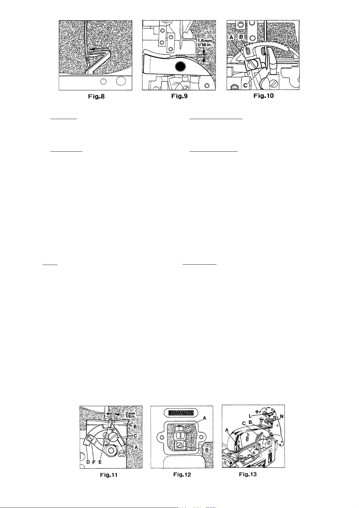
SETTING HEIGHT OF NEEDLESETTING HEIGHT OF NEEDLE
SETTING HEIGHT OF NEEDLE
SETTING HEIGHT OF NEEDLESETTING HEIGHT OF NEEDLE
The height of the needle is correct, when the top of its eye
is flush with the lower edge of the lloper, when the looper
moves to the left and its point is flush with the left side of
the needle (see Fig. 8).
SAFETY RULES!SAFETY RULES!
SAFETY RULES!
SAFETY RULES!SAFETY RULES!
Beachten Sie die
EINSTELLUNG DES GREIFERSEINSTELLUNG DES GREIFERS
EINSTELLUNG DES GREIFERS
EINSTELLUNG DES GREIFERSEINSTELLUNG DES GREIFERS
1. Greifer für Zweifaden-Doppelkettenstich:
Stellen Sie den Greifer (A, Fig. 6) so, daß der Abstand von Nadelmitte (B) bis zur Greiferspitze nicht weniger als 4 mm beträgt,
wenn der Greifer in der von der Nadel entferntesten Enstellung
ist. Die Greifereinstelllehre Nr. 21225-4/4.4 erleichtert diese Einstellung.
2. Greifer für Einfaden-Einfachkettenstich:
Stellen Sie den Greifer (A, Fig. 6A) so, daß der Abstand von Nadelmitte (B) bis zur Greiferspitze nicht weniger als 3,6 mm beträgt,
wenn der Greifer in der von der Nadel entferntesten Endstellung
ist. Die Greifereinstelllehre Nr. 21225-9/64 erleichtert diese Einstellung.
Ist eine Einstellung notwendig, entfernen Sie den Verschlußstopfen (C, Fig. 7). Durch diese Bohrung ist die Befestigungsschraube für die Greiferwelle zugänglich. Lösen Sie die Schraube und schieben Sie die Greiferwelle nach rechts oder links, bis
der Abstand 4 bzw. 3,6 mm erreicht ist. Die Greiferspitze soll so
dicht wie möglich hinter der Nadel vorbei gehen, ohne diese zu
berühren (0,08 - 0,13 mm Abstand). Ziehen Sie die Schraube wieder an und montieren Sie den Verschlußstopfen.
EINSTELLUNG DER NADELHÖHEEINSTELLUNG DER NADELHÖHE
EINSTELLUNG DER NADELHÖHE
EINSTELLUNG DER NADELHÖHEEINSTELLUNG DER NADELHÖHE
Die Nadelhähe ist richtig eingestellt, wenn sich Oberkante Nadelöhr und Unterkante Greifer decken, wenn der Greifer sich
nach links bewegt und die Greiferspitze mit der linken Seite der
Nadel bündig ist (siehe Fig. 8).
SICHERHEITSHINWEISE!SICHERHEITSHINWEISE!
SICHERHEITSHINWEISE!
SICHERHEITSHINWEISE!SICHERHEITSHINWEISE!
If adjustment is necessary, loosen set screw (D, Fig. 7) and
remove needle, then loosen lock nut (E) and regulate the
height adjustment screw (A). Now reset stop screw (B) in
feed dog to maintain the adjusted feed dog height.
SETTING THE LOWER FEED DOGSETTING THE LOWER FEED DOG
SETTING THE LOWER FEED DOG
SETTING THE LOWER FEED DOGSETTING THE LOWER FEED DOG
The lower feed dog is set correctly when its teeth rise slightly
more than the depth of a full tooth (approx. 1.6 mm (1/
16") above the throat plate (see Fig. 9). To raise or lower
the feed dog loosen screw (A, Fig. 10) and set the feed
dog to the specified height. Retighten screw (A). Now reset
stop screw (B) in feed dog to maintain the adjusted feed
dog height.
NEEDLE GUARDNEEDLE GUARD
NEEDLE GUARD
NEEDLE GUARDNEEDLE GUARD
Set the needle guard (C, Fig. 10) so that it just touches the
needle when it is at its most forward point of travel. To move
guard forward or backward loosen screw (A) and move
needle guard as required. Retighten screw.
NOTE: Screw (A) serves also to fasten the lower feed dog.
Therefore make sure not to disturb the feed dog height
when setting the needle guard.
Ist eine Einstellung notwendig, lösen Sie die Befestigungsschraube
(D, Fig. 7) und entfernen Sie die Nadel; dann lösen Sie die Mutter (E) und regulieren die Höhen-Einstellschraube (F) entsprechend auf die richtige Nadelhöhe. Ziehen Sie die Mutter (E) wieder an, damit diese Einstellung erhalten bleibt.
EINSTELLUNG DES UNTEREN TRANSPOREINSTELLUNG DES UNTEREN TRANSPOR
EINSTELLUNG DES UNTEREN TRANSPOR
EINSTELLUNG DES UNTEREN TRANSPOREINSTELLUNG DES UNTEREN TRANSPOR
Der untere Transporteur ist richtig eingestellt, wenn die Transporteurzähne die Stichplatte etwas mehr als eine volle Zahnhöhe
(ca. 1,6 mm) überragen (siehe Fig. 9).
Zum Höher- oder Tieferstellen des Transporteurs lösen Sie die
Schraube (A, Fig. 10) und stellen den Transporteur auf die vorgeschriebene Höhe. Ziehen Sie die Schraube (A) wieder an. Nun
stellen Sie die Anschlagschraube (B) im Transporteur so, daß die
eingestellte Transporteurhöhe erhalten bleibt.
NADELANSCHLAGNADELANSCHLAG
NADELANSCHLAG
NADELANSCHLAGNADELANSCHLAG
Stellen Sie den Nadelanschlag (C, Fig. 10) so, daß er die Nadel
gerade leicht berührt, wenn er am vordersten Punkt seiner Bewegung steht. Zum Verstellen des Anschlags nach vorne oder
hinten lösen Sie die Schraube (A) und stellen den Anschlag entsprechend ein. Ziehen Sie die Schraube wieder an.
BEACHTEN SIE: Mit der Schraube (A) wird gleichzeitig der untere
Transporteur befestigt. Beachten Sie deshalb beim Einstellen des
Nadelanschlags, daß die Transporteurhöhe nicht verändert wird.
TEURSTEURS
TEURS
TEURSTEURS
14
Page 15
SETTING OF THE KNIVESSETTING OF THE KNIVES
SETTING OF THE KNIVES
SETTING OF THE KNIVESSETTING OF THE KNIVES
1. Fixed knife:
Set the fixed knife (A, Fig. 11) so that its tip sits close to
the underside of the throat plate (B). For adjustment
loosen screw (C) and move knife up or down in its
holder as required. Retighten screw.
2. Moving knife:
Set the moving knife (D, Fig. 11) so that is just clears
below the throat plate underside on its entire arc of
travel. In the most open position of the knives the pilot
(E) should overlap the fixed knife by 3 mm (1/8"). In
cutting position of the knives the cutting edge of the
moving knife should overlap the cutting edge of the
fixed knife at least 1 mm (3/64"). For adjusting moving
knife loosen screw (F) and set knife as required.
Retighten screw.
STITCH LENGTHSTITCH LENGTH
STITCH LENGTH
STITCH LENGTHSTITCH LENGTH
To change the stitch length, remove the cover plate
located below the serial number of the machine. Loosen
lock nut (A, Fig. 12) and turn stitch length adjusting screw
(B) clockwise to shorten stitch or counterclockwise to
lengthen it.
After adjustment, retighten lock nut (A) and replace the
cover plate.
EINSTELLUNG DER MESSEREINSTELLUNG DER MESSER
EINSTELLUNG DER MESSER
EINSTELLUNG DER MESSEREINSTELLUNG DER MESSER
1. Feststehendes Messer:
Stellen Sie das feststehende Messer (A, Fig. 11) so, daß seine
Spitze an der Stichplattenunterseite (B) anleigt. Zum Einstellen lösen Sie die Schraube (C) und schieben das Messer im
Halter nach Bedarf nach oben oder unten. Ziehen Sie die
Schraube wieder an.
2. Bewegliches Messer:
Stellen Sie das bewegliche Messer (D, Fig. 11) so, daß es innerhalb seiner Schwingbewegung unter der Stichplattenunterseite gerade freigeht. Der Führungszapfen (E) soll in der am
weitesten geöffneten Stellung der Messer das feststehende
Messer 3 mm überlappen. In Schneidstellung muß die Schneide des beweglichen Messers mindestens 1 mm überlappen.
Zum Einstellen des beweglichen Messers lösen Sie die Schraube (F) und stellen das Messer entsprechend ein.
Ziehen Sie die Schraube wieder an.
STICHLÄNGESTICHLÄNGE
STICHLÄNGE
STICHLÄNGESTICHLÄNGE
Zum Verändern der Stichlänge entfernen Sie den Deckel unter
der Seriennummer der Maschine.
Lösen Sie die Mutter (A, Fig. 12) und drehen die Stichlängenstellschraube (B) im Uhrzeigersinn, um den Stich zu verkürzen oder
im Gegenuhrzeigersinn, um ihn zu verlängern. Ziehen Sie die
Mutter (A) nach dieser Einstellung wieder an und schrauben den
Deckel wieder auf.
NOTE: Any change in the stitch length necessitates
corresponding change in the needle guard setting.
THREAD GUIDESTHREAD GUIDES
THREAD GUIDES
THREAD GUIDESTHREAD GUIDES
Set the needle thread take-up (A, Fig. 13) so that the
needle thread contacts the hook (A) just when the needle
thread loop leaves the looper point.
The needle thread eyelet (B) is set correctily when the
eyelet dips about 30° to the left.
The looper thread eyelet (C) controlls the looper thread.
It is set correctly when it takes up slack of the looper thread
when the looper moves to the right.
THROATHROA
T PLAT PLA
THROA
THROATHROA
For closing of thin and soft fabric an auxiliary needle hole
section on the needle hole of the throat plate is required:
1 - part No. 2130 Needle hole section
1 - part No. 77K Screw
For extremely thin fabric ist is recommended to use in
connection with these parts needle sizes 125/049 or 170/
067 and sewing thread size Ne 34/4 (also refer to
paragraph "NEEDLES").
TE NEEDLE HOLE SECTION FOR THIN FTE NEEDLE HOLE SECTION FOR THIN F
T PLA
TE NEEDLE HOLE SECTION FOR THIN F
T PLAT PLA
TE NEEDLE HOLE SECTION FOR THIN FTE NEEDLE HOLE SECTION FOR THIN F
ABRICSABRICS
ABRICS
ABRICSABRICS
BEACHTEN SIE: Jede Änderung der Stichlänge erfordert ein entsprechendes Nachstellen des Nadelanschlags.
FF
ADENFÜHRUNGENADENFÜHRUNGEN
F
ADENFÜHRUNGEN
FF
ADENFÜHRUNGENADENFÜHRUNGEN
Stellen Sei den Nadelfadenzug (A, Fig. 13) so ein, daß der Nadelfaden den Haken (A) berührt, wenn die Nadelfadenschlinge die
Greiferspitze verläßt.
Die Nadelfadenführung (B) ist richtig eingestellt, wenn sie etwa
30° nach links geneigt steht.
Die Greiferfadenführung (C) kontrolliert den Greiferfaden. Sie ist
richtig eingestellt, wenn der lose Greiferfaden bei der Bewegung
des Greifers nach rechts aufgenommen wird.
STICHLOCHAUFLAGE FÜR DÜNNE STOFFESTICHLOCHAUFLAGE FÜR DÜNNE STOFFE
STICHLOCHAUFLAGE FÜR DÜNNE STOFFE
STICHLOCHAUFLAGE FÜR DÜNNE STOFFESTICHLOCHAUFLAGE FÜR DÜNNE STOFFE
Zum Zunähen dünner und weicher Stoffe ist zusätzlich eine Stichlochauflage über dem Stichloch der Stichplatte erforderlich.
1 - Teil Nr. 2130 Stichlochauflage
1 - Teil Nr. 77K Schraube
Bei besonders dünnen Sackstoffen ist es zweckmäßig in Verbindung mit diesen Teilen, die Nadeldicken 125/049 oder 170/067
und die Nähgarnstärke Ne 34/4 zu verwenden (siehe auch Abschnitt "NADELN").
15
Page 16
CAUTION!CAUTION!
CAUTION!
CAUTION!CAUTION!
ACHTUNG!ACHTUNG!
ACHTUNG!
ACHTUNG!ACHTUNG!
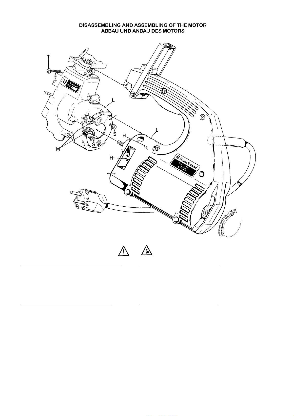
Pull out the mains plug before disassembling or assembling to motor!
Disassembling the motor from the sewing machine:
1. Remove screw (T).
2. Loosen screw (S).
3. Hold the sewing machine, turn the motor clockwise until
it stops and pull it out of the sewing machine.
Assembling the motor to the sewing machine:
1. Turn the gears until the marks (M) on both gears are
opposite to each other, as shown, before inserting the
pinion of the motor.
2. Align the two holes (H) in the motor housing with the
hex. head cap screws (S) in the sewing machine and
push the motor and sewing machine together.
3. Hold the sewing machine and turn the motor
counterclockwise until the parting lines (L) of the housing
halves on motor and sewing machine are aligned.
Tighten screws (S)
4. Fasten the thread cone support with screw (T) on the
handle of the motor housing.
Ziehen Sie den Netzstecker bevor Sie den
Motor ab- oder anbauen!
Abbau des Motors von der Nähmaschine:
1. Entfernen Sie die Schraube (T).
2. Lösen Sie die Schrauben (S).
3. Halten Sie die Nähmaschine fest; drehen Sie am Motor im Uhrzeigersinn bis zum Anschlag und ziehen Sie ihn aus der Nähmaschine.
Anbau des Motors an die Nähmaschine:
1. Drehen Sie die Zahnräder bis sich die Markierungen (M) auf beiden Zahnrädern, wie gezeigt, gegenüberstehen, bevor das Ritzel
des Motors eingeschoben wird.
2. Richten Sie die beiden Bohrungen (H) im Motorgehäuse zu den
beiden Sechskantschrauben (S) in der Nähmaschine aus und
schieben Sie Motor und Nähmaschine zusammen.
3. Halten Sie die Nähmaschine fest und drehen Sie den Motor soweit im Gegenuhrzeigersinne bis die Trennlinien (L) der Gehäusehälften von Motor und Nähmaschine in einer Linie sind.
Ziehen Sie die Schrauben (S) an.
4. Befesten Sie den Garnrollenträger mit der Schraube (T) am Handgriff des Motorgehäuses.
16
Page 17

ORDERING WEAR AND SPORDERING WEAR AND SP
ORDERING WEAR AND SP
ORDERING WEAR AND SPORDERING WEAR AND SP
ARE PARE P
ARE P
ARE PARE P
ARAR
AR
ARAR
BESTELLUNG VON VERSCHLEISS- UND ERSABESTELLUNG VON VERSCHLEISS- UND ERSA
BESTELLUNG VON VERSCHLEISS- UND ERSA
TSTS
TS
TSTS
BESTELLUNG VON VERSCHLEISS- UND ERSABESTELLUNG VON VERSCHLEISS- UND ERSA
TZTEILENTZTEILEN
TZTEILEN
TZTEILENTZTEILEN
The following section of this manual simplifies ordering wear
and spare parts. Exploded views of various sections of the
mechanism are shown so that the parts may be seen in
their actual position in the sewing machine. On the page
opposite the illustration will be found a listing of the parts
with their part numbers, descriptions and the number of
pieces required in the particular view being shown.
Numbers in the first column are reference numbers only,
and merely indicate the position of that part in the
illustration. Reference numbers should never be used in
ordering parts. Always use the part number listed in the second column.
Component parts of sub-assemblies which can be furnished
for repairs are indicated by intending their descriptions
under the description of the main sub-assembly.
At the back of the manual will be found a numerical index
of all parts shown in this manual. This will facilitate locating
the illustration and description when only the part number
is known.
IMPORIMPOR
TT
ANT!ANT!
IMPOR
T
ANT! ON ALL ORDERS, PLEASE INCLUDE PART
IMPORIMPOR
TT
ANT!ANT!
NUMBER, PART NAME, QUANTITY REQUIRED
AND STYLE OF MACHINE FOR WHICH PART IS
ORDERED.
Der folgende Teil diese Katalogs vereinfacht die Bestellung
von Verschleiß- und Ersatzteilen. Explosionszeichnungen der
einzelnen Gruppen des Mechanismus zeigen die Lage der
Einzelteile in der Nähmaschine. Auf der der Bildseite gegenüberliegenden Seite befindet sich ein Verzeichnis der
Teile mit Teilenummer, Beschreibungen und der für den
gezeigten Bildausschnitt benötigten Anzahl.
Die Nummern in der ersten Spalte sind Positionsnummern
und zeigen lediglich, wo das Teil in der Abbildung zu finden
ist. Positionsnummern dürfen bei Teilebestellungen nie verwendet werden. Verwenden Sie immer die Teilenummer in
der zweiten Spalte.
Einzelteile von Komplettteilen, die als Ersatzteile geliefert
werden können, sind durch Einrücken ihrer Beschreibung
unterhalb der Beschreibung des Komplettteiles gekennzeichnet.
Am Ende des Katalogsbefindet sich ein Nummernverzeichnis sämtlicher im Katalog dargestellten Teile. Dies erleichtert das Auffinden der Abbildung und Beschreibung, wenn
nur die Teilenummer bekannt ist.
WICHTIG!WICHTIG!
WICHTIG! BITTE GEBEN SIE AUF ALLEN BESTELLUNGEN
WICHTIG!WICHTIG!
DIE TEILENUMMER, DIE TEILEBESCHREIBUNG,
DIE BENÖTIGTE MENGE UND DEN MASCHINENTYP, FÜR DEN DAS TEIL BESTELLT WIRD, AN.
17
Page 18

18
Page 19

HOUSING ASSEMBLY, BUSHINGS FOR LOOPER SHAFT
GEHÄUSE KOMPLETT, BUCHSEN FÜR GREIFERWELLE
Ref. No.
Pos. No.
1 - 14
1
2
3
4
5
6
7
8
9
10
11
12
13
14
15*
16*
17*
18*
Part No.
Teil Nr.
2129B
99266A
99266
96523
2192
2190
96511
G41046G
76099D
2195N
2194
2193
2193A
999-104A
2165D0.1
2165D0.2
2165D0.3
2165D0.5
2165D1.0
2165C0.5
2191
2140N
2165A
Description
Housing Assembly
Shoulder Screw
Shoulder Screw (for screwing together
the housing halves)
Parallel Pin
Bushing
Bushing
Parallel Pin
Spring Valve Oiler
Parallel Pin
Bushing
Bushing
Bushing
Bushing
Plug
Shim Ring 6 x 12, 0.1 mm (.004") thick
Shim Ring 6 x 12, 0.2 mm (.008") thick
Shim Ring 6 x 12, 0.3 mm (.012") thick
Shim Ring 6 x 12, 0.5 mm (.020") thick
Shim Ring 6 x 12, 1.0 mm (.040") thick
Shim Ring 8 x 14, 0.5 mm (.020") thick
Bushing for looper shaft
Bushing for looper shaft
Gear
Beschreibung
Gehäuse komplett
Ansatzschraube
Ansatzschraube (zum Zusammenschrauben der Gehäusehälften)
Zylinderstift
Buchse
Buchse
Zylinderstift
Kugelöler
Zylinderstift
Bundbuchse
Buchse
Buchse
Buchse
Verschlussstopfen
Paßscheibe 6 x 12, 0,1 mm dick
Paßscheibe 6 x 12, 0,2 mm dick
Paßscheibe 6 x 12, 0,3 mm dick
Paßscheibe 6 x 12, 0,5 mm dick
Paßscheibe 6 x 12, 1,0 mm dick
Paßscheibe 8 x 14, 0.5 mm dick
Buchse für Greiferwelle
Buchse für Greiferwelle
Zahnrad
Amt. Req.
Anzahl
1
1
4
1
2
2
2
4
1
2
2
1
1
1
2
2
2
2
2
1
1
1
* Part of sewing machine.
MOUNTING INSTRUCTION
MONTAGEHINWEISE
Hold Gear 18 and Shim Ring 15 against the Flanged Bushing
9. Measure the distance between Gear Hub and lower Bushing 10 by means of a Thickness Gauge. By choosing one of
the above listed Shim Rings 14, adjust clearance to the
smallest axial play (approx. 0.03 - 0.10 mm).
* Bestandteil der Nähmaschine.
Legen Sie das Zahnrad 18 mit Paßscheibe 15 gegen
die Bundbuchse 9 an. Ermitteln Sie den Abstand zwischen Zahnradnabe und unterer Buchse 10 mit einer
Fühlerlehre. Stellen Sie durch Auswahl der oben aufgelisteten Paßscheiben14 das geringste Axialspiel ein
(ca. 0,03 - 0,10 mm).
19
Page 20

20
Page 21

COVER ASSEMBLY, THREAD CONE SUPPORT, UPPER FEED DRIVE MECHANISM, PRESSER FOOT LEVER, UPPER FEED DOG, PRESSEER FOOT,
THREAD GUIDES
ABDECKUNG KOMPLETT, GARNROLLENHALTER, OBERTRANSPORTANTRIEB, DRÜCKERFUSSHEBEL, OBERTRANSPORTEUR, DRÜCKERFUSS,
Ref. No.
Pos. No.
10
11
12
13
14
15
16
17
18
19
20
21
22
23
24
25
26
27
28
29
30
31
32
33
34
35
36
37
38
39
40
41
42
43
44
45
46
47
48
49
50
51
52
53
54
55
56
57
58
59
60
61
62
Part No.
Teil Nr.
1
G29496
2
51292C
3
51292F1
4
51292F8
5
109
6
2186
7
51292A
8
51192G
9
G43266
2159A
93640
41071G
2163
G22585A
41071G
2176B
2158A
87U
2158D
2158C
22585A
95954
22585B
22528
51758
22585A
51225W
2189H
93B
2189C
79
2289B
99270
2146
2196A
99268
G29493B
2166A
28C
2176D
2193
2196B
96663
93
2167A
2168A
2169A
12934A
2175A
2143
907
2178
80175
2160N
2179
2180
80175
2126
87A
2120
87A
95580
Description Beschreibung Amt. Req.
Cover Assembly
Tension Nut
Tension Spring for Looper Thread
Tension Spring for Needle Thread
Tension Disc
Tension Post
Tension Post Ferrule
Tension Eyelet
Nut
Cover
Thum Screw
Nut
Leaf Spring
Screw
Nut
Spring Rest
Needle Thread Take-up
Screw
Needle Thread Eyelet
Looper Thread Eyelet
Screw
Washer
Screw
Screw
Needle Thread Eyelet for Single
Thread Chainstitch, Type 101
Screw
Washer
Thread Cone Support
Screw
Thread Rod
Screw
Spool Pin
Thumb Screw
Connecting Rod
Bushing
Shoulder Screw
Feed Lever and Presser Foot Lever
Collar
Set Screw
Feed Lever
Bushing
Bushing
Roll Pin
Screw
Crank
Link
Shank Screw
Nut
Presser Foot Lever
Bushing
Nut
Feed Rocker
Screw
Double Ball Joint
Upper Feed Shaft
Upper Feed Dog Holder
Screw
Upper Feed Dog, marked "GA"
Countersunk Screw
Presser Foot
Countersunk Screw
Screw (Part of the Motor Assy.)
FADENFÜHRUNGEN
Abdeckung komplett
Fadenspannungsmutter
Spannungsfeder für Greiferfaden
Spannungsfeder für Nadelfaden
Fadenspannungsscheibe
Fadenspannungsbolzen
Fadenspannungshülse
Fadenführung
Mutter
Abdeckung
Rändelschraube
Mutter
Blattfeder
Schraube
Mutter
Federauflage
Nadelfadenabzug
Schraube
Nadelfadenführung
Greiferfadenführung
Schraube
Scheibe
Schraube
Schraube
Nadelfadenführung für Einfachkettenstich, Nähstichtyp 101
Schraube
Scheibe
Garnrollenträger
Schraube
Fadenstange
Schraube
Spulenstift
Rändelschraube
Schubstange
Buchse
Ansatzschraube
Transporthebel und Drückerfußhebel, kpl.
Stellring
Gewindestift
Transporthebel
Buchse
Buchse
Spannhülse
Schraube
Kurbel
Gelenk
Schaftschraube
Mutter
Drückerfußhebel
Buchse
Mutter
Transportantriebshebel
Schraube
Doppelkugelgelenk
Welle für Obertransport
Halter für Obertransporteur
Schraube
Obertransporteur, gezeichnet "GA"
Senkschraube
Drückerfuß
Senkschraube
Schraube (Bestandteil des kompl. Motors)
Anzahl
1
2
1
1
4
2
2
2
2
1
1
1
2
2
2
1
1
1
1
1
2
2
1
1
1
1
1
1
3
1
1
2
2
1
2
1
1
1
1
1
2
1
2
1
1
1
1
1
1
1
1
1
1
1
1
1
1
1
2
1
2
1
21
Page 22

22
Page 23

HOUSING, CRANKSHAFT, NEEDLE-, LOOPER-, FEED- AND CHAINCUTTER MECHANISM, FEED DOG, LOOPER, THROAT PLATE, COVERS
GEHÄUSE, KURBELWELLE, NADEL-, GREIFER-, TRANSPORT- UND KETTENABSCHNEIDERANTRIEB, TRANSPORTEUR, GREIFER, STICHPLATTE,
Ref. No.
Pos. No.
10
11
12
13
14
15
16
17
18
19
20
21
22
23
24
25
26
27
28
29
30
31
32
35
36
37
38
39
40
41
42
43
44
45*
46
47
48
48A*
49
50
51
52
53
54
55
56
57
58
59
60**
61
62
63
64
65-115
1
2
3
4
5
6
7
8
9
Part No.
Teil Nr.
2105
99277
80175
2125
G29492
73C
96502
2152B
2152
2142
2151
28C
96602
G660-210
96603
G660-210
41071G
2158E
22575
2177
88B
28C
2145A
28
2158B
22768
2115
96501
99267
12934A
2108
2108B
99521
2173A
22560B
2191
2144
88B
2134A
2193
2135P
22596
73C
2153
HA61D
2140N
2135R
2156
39250J
2139N
51225W
G660-210
2136
2131
2195N
2165C0.5
2165A
2194
2165D0.1
2165D0.2
2165D0.3
2165D0.5
2165D1.0
22560B
22764A
2133
2132
Description Beschreibung Amt. Req.
Feed Dog
Set Screw
Screw
Needle Guard, marked "TS"
Looper Drive Assembly
Set Screw
Parallel Pin
Connection
Ball Joint
Lever for Looper Drive
Link
Set Screw
Pin
Retaining Ring
Pin
Retaining Ring
Nut
Thread Eyelet
Set Screw
Bolt
Set Screw
Set Screw
Guide
Screw
Thread Eyelet
Screw
Needle Lever
Parallel Pin
Screw for Needle
Nut
Looper for Double Locked Stitch, type 401
Lpr for Single Thread Chainstitch, type 101
Spring Washer
Knife Rocker
Set Screw
Bushing for Looper Shaft
Looper Shaft
Set Screw
Feed Dog Holder
Bushing
Feed Rocker
Screw
Screw
Guide Block
Screw
Bushing for Looper Shaft
Spacer
Looper Rocker
Nut
Double Ball Joint
Washer
Retaining Ring
Bolt
Feed Rocker Shaft
Flanged Bushing
Shim Ring 8 x 14, 0.5 mm (.020") thick
Gear
Bushing
Shim Ring 6 x 12, 0.1 mm (.004") thick
Shim Ring 6 x 12, 0.2 mm (.008") thick
Shim Ring 6 x 12, 0.3 mm (.012") thick
Shim Ring 6 x 12, 0.5 mm (.020") thick
Shim Ring 6 x 12, 1.0 mm (.040") thick
Set Screw
Set Screw with Cone Point
Inset
Stitch Length Adjusting Screw
See following page
ABDECKUNGEN
Transporteur
Gewindestift
Schraube
Nadelanschlag, gezeichnet "TS"
Greiferantrieb komplett
Gewindestift
Zylinderstift
Gelenkstück
Kugelgelenk
Hebel für Greiferantrieb
Gelenk
Gewindestift
Stift
Sicherungsring
Stift
Sicherungsring
Mutter
Fadenöse
Gewindestift
Bolzen
Gewindestift
Gewindestift
Führung
Schraube
Fadenöse
Schraube
Nadelhebel
Zylinderstift
Schraube für Nadel
Mutter
Greifer für Doppelkettenstich, Typ 401
Greifer für Einfachkettenstich, Typ 101
Federscheibe
Messerantriebshebel
Gewindestift
Buchse für Greiferwelle
Greiferwelle
Gewindestift
Transporteurhalter
Buchse
Brückenhebel
Schraube
Gewindestift
Mitnehmer
Schraube
Buchse für Greiferwelle
Distanzbuchse
Hebel für Greiferführung
Mutter
Doppelkugelgelenk
Scheibe
Sicherungsring
Bolzen
Transportantriebswelle
Bundbuchse
Paßscheibe 8 x 14, 0,5 mm dick
Zahnrad
Buchse
Paßscheibe 6 x 12, 0,1 mm dick
Paßscheibe 6 x 12, 0,2 mm dick
Paßscheibe 6 x 12, 0,3 mm dick
Paßscheibe 6 x 12, 0,5 mm dick
Paßscheibe 6 x 12, 1,0 mm dick
Gewindestift
Gewindestift mit Spitze
Einlage
Stichlängen-Stellschraube
Siehe nächste Seite
Anzahl
1
1
1
1
1
1
1
1
1
1
1
3
1
2
1
2
1
1
1
1
3
1
1
2
1
1
1
1
1
1
1
1
1
1
1
1
1
1
1
1
2
1
1
1
1
1
1
1
1
1
2
1
1
1
1
2
2
2
2
2
2
2
2
2
2
2
1
1
* These parts have to be secured with engineering
adhesive part No. 999-114B.
** Use the shim ring as required, according
to the "MOUNTING INSTRUCTIONS", page 19.
23
* Diese Teile müssen mit dem Konstruktionskleber
Teil Nr. 999-114B gesichert werden.
** Verwenden Sie die Paßscheiben nach
Bedarf, entsprechend der "MONTAGEHINWEISE", Seite 19.
Page 24
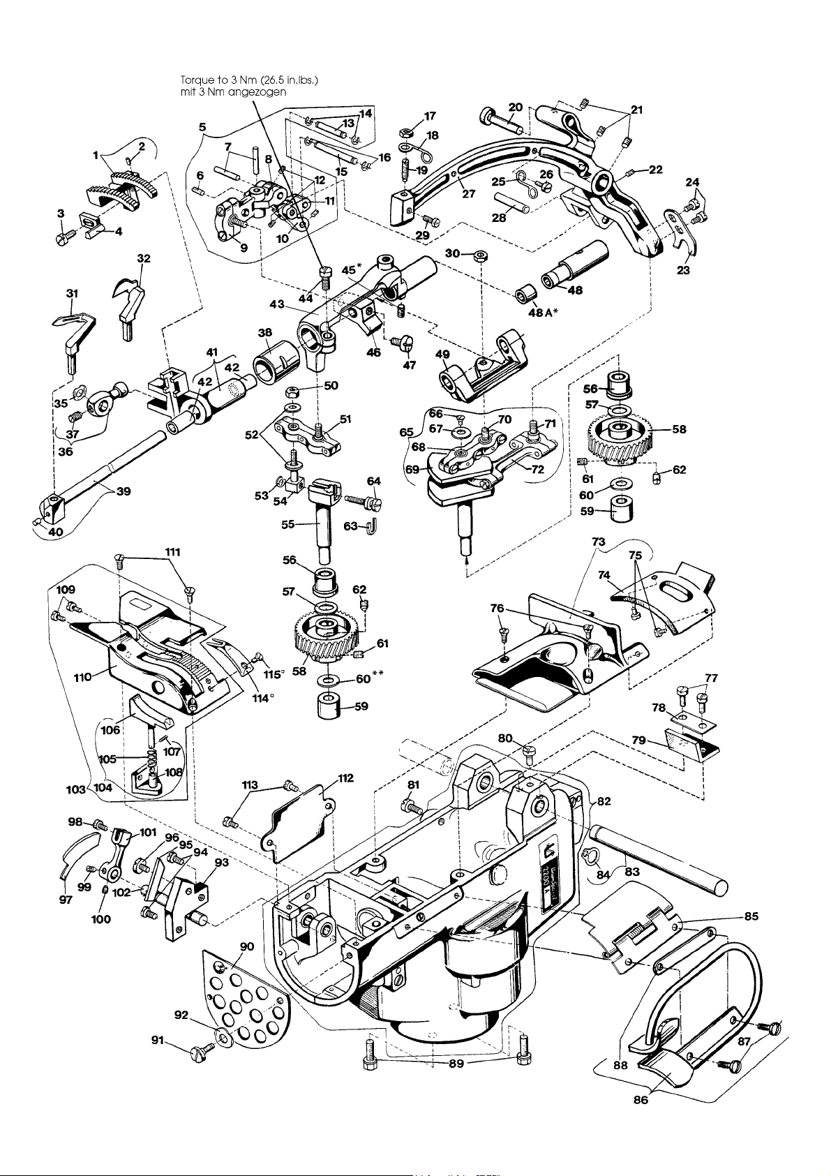
24
Page 25

HOUSING, CRANKSHAFT, NEEDLE-, LOOPER-, FEED- AND CHAINCUTTER MECHANISM, FEED DOG, LOOPER, THROAT PLATE, COVERS
GEHÄUSE, KURBELWELLE, NADEL-, GREIFER-, TRANSPORT- UND KETTENABSCHNEIDERANTRIEB, TRANSPORTEUR, GREIFER, STICHPLATTE,
Ref. No.
Pos. No.
1-64
100
101
102
103
104
105
106
107
108
109
110
111
112
113
114°
115°
65
66
67
68
69
70
71
72
73
74
75
76
77
78
79
80
81
82
83
84
85
86
87
88
89
90
91
92
93
94
95
96
97
98
99
Part No.
Teil Nr.
G29490
22561
2148
2155
2122
2154
G10349
2145
2101
2182A
28
87A
22585
2182C
2182B
22528
22585B
2129B
2141
96256
2157
2203E
22585B
2103AC
99373
2183
99269
J1614
2150
538
2149
22542
2170
73
22764
88
2171
2172D
G29497
G2127
2127C
G2127A
96650
2127B
87U
2124
87A
2182
22585A
2130
77K
Description Beschreibung Amt. Req.
See preceding page
Crank Shaft Assembly
Screw
Washer
Double Ball Joint
Crank Shaft
Ball Stud
Ball Stud
Double Link Bearing
Cover Assembly
Rubber Plate
Screw
Countersunk Srew
Screw
Washer Plate
Rubber Plate
Screw for Cover
Screw For Cover
Housing Assembly, Parts see Page 19
Needle Lever Shaft
Retaining Ring
Hinges Cover
Bag Feed-in Guide and Finger Guard
Screw
Washer Plate
Hex. Head Cap Screw
Cover, punched
Shoulder Screw
Spring Washer
Holder for Fixed Knife
Screw
Knife, fixed
Screw
Knife, moving
Screw
Set Screw with Cone Point
Set Screw
Knife Lever
Shaft for Knife Lever
Throat Plate and Chaining Block Assembly
Chaining Block Assembly
Spring
Chaining Block
Roll Pin
Guide for Chaining Block
Screw
Throat Plate
Countersunk Screw
Cover
Screw
Needle Hole Section, marked "UO"
Countersunk Screw
ABDECKUNGEN
Siehe vorgehende Seite
Kurbe1welle komplett
Schraube
Scheibe
Doppelkugelgelenk
Kurbelwelle
Kugelschraube
Kugelschraube
Doppellager
Abdeckung komplett
Abdeckgummi
Schraube
Senkschraube
Schraube
Unterlegplatte
Abdeckgummi
Schraube für Abdeckung
Schraube für Abdeckung
Gehäuse kpl., Einzelteile siehe Seite 19
Nadelhebelwelle
Sicherungsring
Verschlußklappe
Sackeinführung und Fingerabweiser
Schraube
Unterlegplatte
Sechskantschraube
Anschlußblech, gelocht
Ansatzschraube
Federscheibe
Halter für feststehendes Messer
Schraube
Messer, feststehend
Schraube
Messer, beweglich
Schraube
Gewindestift mit Spitze
Gewindestift
Messerhebel
Welle für Messerhebel
Stichplatte mit Kettelfuß komplett
Kettelfuß komplett
Feder
Kettelfuß
Spannhülse
Führung für Kettelfuß
Schraube
Stichplatte
Senkschraube
Deckel
Schraube
Stichlochauflage, gezeichnet "UO"
Senkschraube
Anzahl
1
1
1
1
1
1
1
1
1
1
2
2
2
1
1
1
1
1
1
1
1
1
1
2
1
2
1
1
1
1
2
1
1
1
1
1
1
1
1
1
1
1
1
1
2
1
2
1
2
1
1
° Extra order and charge item.
25
° Gegen zusätzliche Bestellung und Berechnung.
Page 26

26
Page 27

TAPE FOLDER AND MECHANICAL TAPE CUTTING DEVICE
BANDEINFASSAPPARAT UND MECHANISCHER BANDABSCHNEIDER
Ref. No.
Pos. No.
1 - 49
1
2
3
4
5
6
7
8
9
10
11
12
13
14
15
16
17
18
19
20
21
22
23
24
25
26
27
28
29
30
31
32
33
34
35
36
37
38
39
40
41
42
43
44
45
46
47
48*
49
Part No.
Teil Nr.
G29901A50
G29901A60
93077
G41041B
22837
93077C
80640E
93077D
93077A
93077B
22542
93
9937
93077E
22874
G29497A
87U
G2127
2127B
2127C
G2127A
96650
2103A-50
2103A-60
2103AA-50
2103AA-60
99269
J1614
2103AB
39250J
22585A
2103AC
G29486E
99555
99556
22585R
80275
99560
22848
94
99558
2170A
22724
96701
99557
99559
22570A
402
22562
2157E
2188
2188C
99271
Description Beschreibung Amt. Req.
Tape Folder and Mechanical Tape
Cutting Device for 50 mm wide tape
Tape Folder and Mechanical Tape
Cutting Device for 60 mm wide tape
Tape Reel Assembly
Collar
Thumb Screw
Spring
Bushing
Tape Reel Disc
Tape Reel Bracket
Tape Guide
Screw
Screw
Nut
Plate
Screw
Throat Plate and Chaining Block Assembly
Screw
Chaining Block Assembly
Guide for Chaining Block
Spring
Chaining Block
Roll Pin
Folder Assembly for 50 mm wide tape
Folder Assembly for 60 mm wide tape
Folder for 50 mm wide tape
Folder for 60 mm wide tape
Shoulder Screw
Spring Washer
Folder Bracket
Nut
Screw
Shim
Tape Clipper
Knife Actuating Lever
Bracket for knife shaft
Screw
Lower Knifer
Finger Guard
Screw
Screw
Guide
Upper Knife
Screw
Spring
Knife Shaft
Spring
Screw
Stop Screw
Screw for guide 99558
Front Cover (not shown)
Support Arm
Support Arm for 2200L, LA
Screw
Bandeinfassapparat und mechanischer
Bandabschneider für 50 mm breites Band
Bandeinfassapparat und mechanischer
Bandabschneider für 60 mm breites Band
Bandrolle komplett
Stellring
Rändelschraube
Feder
Buchse
Bandrollenscheibe
Bandrollenhalter
Bandführung
Schraube
Schraube
Mutter
Platte
Schraube
Stichplatte mit Kettelfuß, komplett
Schraube
Kettelfuß, komplett
Führung für Kettelfuß
Feder
Kettelfuß
Spannhülse
Apparat kpl. für 50 mm breites Band
Apparat kpl. für 60 mm breites Band
Apparat für 50 mm breites Band
Apparat für 60 mm breites Band
Ansatzschraube
Federscheibe
Apparatehalter
Mutter
Schraube
Unterlegplatte
Bandabschneideapparat, komplett
Messer Betätigungshebel
Messerwellenlager
Schraube
Untermesser
Fingerschutz
Schraube
Schraube
Führungsblech
Obermesser
Schraube
Zugfeder
Messerwelle
Feder
Schraube
Anschlagschraube
Schraube für Führungsblech 99558
Verschlussklappe, kpl. (nicht abgebildet)
Haltebügel
Haltebügel für Federzug für 2200L, LA
Zylinderschraube
Anzahl
1
1
1
1
1
1
2
1
1
2
3
3
1
3
1
2
1
1
1
1
1
1
1
1
1
1
1
1
1
2
1
1
1
1
3
1
1
1
4
1
1
1
1
1
1
2
1
2
1
1
1
1
*Extra order and charge item. *Gegen zusätzliche Bestellung und Berechnung.
27
Page 28

28
Page 29

BAG CLOSING MACHINE 2200AZ4015FAN AND 2200AAZ4015FAN FOR BAG CLOSING UNITS
SACKZUNÄHMASCHINEN 2200AZ4015FAN AND 2200AAZ4015FAN FÜR SACKZUNNÄHANLAGEN
Ref. No.
Pos. No.
1
2
3
4
5
6
7
8
9
10
11
12
13
Part No.
Teil Nr.
22804
80265
2161
2162
2121FAN
2121FA
96256
995-504
2165FAN
88D
22874
2124FAN
999-311
Only the parts found on Styles 2200AZ4015FAN and
2200AAZ4015FAN are illustrated which are different from
those of Styles 2200A and 2200AA.
Description Beschreibung Amt. Req.
Screw
Washer
Ball Bearing
Clamp Plate
Flange Assembly
Flange
Retaining Ring
Ball Bearing
Pinion
Screw
Screw
Throat Plate for cutter below
(not shown)
Cutter, pneumatically actuated, for
Thread Chain (not shown)
Anzahl
Schraube
Unterlagscheibe
Rillenkugellager
Haltestück
Flansch, komplett
Flansch
Sicherungsring 9x1
Rillenkugellager
Ritzel
Linsenzylinderschraube
Zylinderschraube
Stichplatte für nachfolgenden Abschneider
(nicht abgebildet)
Abschneider, pneumatisch betätigt, für
Fadenkette (nicht abgebildet)
Es sind nur die Teile für die Maschinen
2200AZ4015FAN und 2200AAZFAN4015 abgebildet,
die sich von denen für die Maschinen 2200 A und
2200AA unterscheiden.
2
2
1
2
1
1
1
1
1
2
2
1
1
29
Page 30
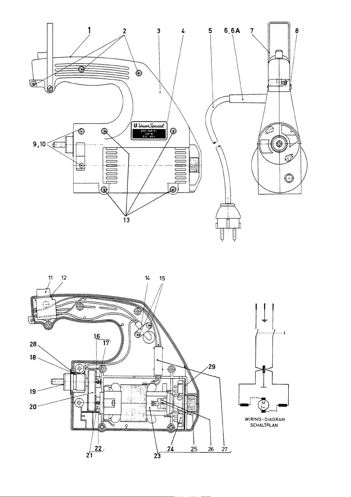
30
Page 31

MOTOR ASSEMBLMOTOR ASSEMBL
MOTOR ASSEMBL
MOTOR ASSEMBLMOTOR ASSEMBL
Protection Class I, with ground wire
MOTOR KOMPLETT TEIL NR. 29929A MOTOR KOMPLETT TEIL NR. 29929A
MOTOR KOMPLETT TEIL NR. 29929A (220-240 V, 50/60 Hz) MASCHINEN 2200A, AA
MOTOR KOMPLETT TEIL NR. 29929A MOTOR KOMPLETT TEIL NR. 29929A
Schutzklasse I, mit Schutzleiter
Y PY P
ARAR
T NO. 29929A T NO. 29929A
Y P
AR
T NO. 29929A (220-240 V, 50/60 Hz) STYLES 2200A, AA
Y PY P
ARAR
T NO. 29929A T NO. 29929A
Ref. No.
Pos. No.
1
2
3
4
5
6
6A*
7
8
9
10
11
12
13
14
15
16
17
18
19
20
21
22
23
23A*
24
25
26
27
28
29*
Part No.
Teil Nr.
29929A
95580
2129M
M129VG
90233B
998-416
998-416L
2288
99271
95665
95257V
998-20B
998-20BA
95581
99654B
95580
2265DA
95515
95182V
2265
999-233
2265C
95515
997A502N
997AE3D502N
995-506A
995-518A
995-524
995-523
2265F
998-20BB
Description Beschreibung Amt. Req.
Motor Assembly
Screw
Motor Housing
Power Plate
Cable with Plug
Protecting Sleeve
Protecting Sleeve, for 2200AE, AAE
Bracket
Screw
Screw
Nut
Thumb Switch
Gasket
Screw
Cable Clamp
Screw
Sprocket Wheel
Screw
Grounding Screw
Pinion with Bearing Assembly
Toothed Belt
Sprocket Wheel
Screw
Built-in Motor
Built-in Motor, for 2200AE, AAE ,
II 3 D T 125° C,
ATEX Directive 94/9/EC
Cooling Fan
Commutator Brush
ALWAYS ORDER IN PAIRS
Lock for Commutator Brush
Radioshielding Capacitor
Contact Washer
Felt, for 2200AE, AAE
Motor komplett
Schraube
Motorgehäuse
Leistungsschild
Kabel mit Stecker
Knickschutztülle
Knickschutztülle für 2200AE, AAE
Haltebügel
Schraube
Schraube
Mutter
Druckknopfschalter
Filzrahmen
Schraube
Kabelschelle
Schraube
Zahnriemenscheibe
Gewindestift
Erdungsschraube
Ritzel mit Lager komplett
Zahnriemen
Zahnriemenscheibe
Gewindestift
Einbaumotor
Einbaumotor für 2200AE, AAE,
II 3 D T 125° C,
ATEX-Richtlinie 94/9/EG
Lüfterflügel
Kohlbebürste
IMMER PAARWEISE BESTELLEN
Verschluß für Kohlebürste
Funkentstörkondensator
Kontaktscheibe
Filz für 2200AE, AAE
Anzahl
1
3
1
1
1
1
1
1
1
2
2
1
1
4
1
2
1
1
1
1
1
1
1
1
1
1
2
2
1
1
2
* Extra order and charge item.
31
* Gegen zusätzliche Bestellung und Berechnung.
Page 32

32
Page 33

MOTOR ASSEMBLMOTOR ASSEMBL
MOTOR ASSEMBL
MOTOR ASSEMBLMOTOR ASSEMBL
Protection Class I, with ground wire green
MOTOR KOMPLETT TEIL NR. 29929BC MOTOR KOMPLETT TEIL NR. 29929BC
MOTOR KOMPLETT TEIL NR. 29929BC (110-115V, 50/60 Hz) MASCHINEN 2200B, BA
MOTOR KOMPLETT TEIL NR. 29929BC MOTOR KOMPLETT TEIL NR. 29929BC
Schutzklasse I, mit Schutzleiter grün
Y PY P
ARAR
T NO. 29929BC T NO. 29929BC
Y P
AR
T NO. 29929BC (110-125V, 50/60 Hz) STYLES 2200B, BA
Y PY P
ARAR
T NO. 29929BC T NO. 29929BC
Ref. No.
Pos. No.
1
2
3
4
5
6
7
8
9
10
11
12
13
14
15
16
17
18
19
20
21
22
23
24
25
26
27
28
Part No.
Teil Nr.
29929BC
95580
2129M
M129VDE
90233BA
998-416
2288
99271
95665
95257V
998-20B
998-20BA
95581
99654B
95580
2265DA
95515
95182V
2265
999-233
2265C
95515
997BC502
995-506A
995-518A
995-524
C55
2265F
Description
Motor Assembly
Screw
Motor Housing
Power Plate
Cable
Protecting Sleeve
Bracket
Screw
Screw
Nut
Thumb Switch
Gasket
Screw
Cable Clamp
Screw
Sprocket Wheel
Screw
Grounding Screw
Pinion with Bearing Assembly
Toothed Belt
Sprocket Wheel
Screw
Built-in Motor
Cooling Fan
Commutator Brush
ALWAYS ORDER IN PAIRS
Lock for Commutator Brush
Plug
Contact Washer
Beschreibung
Motor komplett
Schraube
Motorgehäuse
Leistungsschild
Kabel
Knickschutztülle
Haltebügel
Schraube
Schraube
Mutter
Druckknopfschalter
Filzrahmen
Schraube
Kabelschelle
Schraube
Zahnriemenscheibe
Gewindestift
Erdungsschraube
Ritzel mit Lager komplett
Zahnriemen
Zahnriemenscheibe
Gewindestift
Einbaumotor
Lüfterflügel
Kohlbebürste
IMMER PAARWEISE BESTELLEN
Verschluß für Kohlebürste
Stecker
Kontaktscheibe
Amt. Req.
Anzahl
1
3
1
1
1
1
1
1
2
2
1
1
4
1
2
1
1
1
1
1
1
1
1
1
2
2
1
1
33
Page 34

34
Page 35

MOTOR ASSEMBLMOTOR ASSEMBL
MOTOR ASSEMBL
MOTOR ASSEMBLMOTOR ASSEMBL
Protection Class III, safety extra-low voltage
MOTOR KOMPLETT TEIL NR. 29929F MOTOR KOMPLETT TEIL NR. 29929F
MOTOR KOMPLETT TEIL NR. 29929F (42 V, 50/60 Hz) MASCHINEN 2200F, FA
MOTOR KOMPLETT TEIL NR. 29929F MOTOR KOMPLETT TEIL NR. 29929F
Schutzklasse III, Sicherheitskleinspannung
Y PY P
ARAR
T NO. 29929F T NO. 29929F
Y P
AR
T NO. 29929F (42 V, 50/60 Hz) STYLES 2200F, FA
Y PY P
ARAR
T NO. 29929F T NO. 29929F
Ref. No.
Pos. No.
1
2
3
4
5
6
7
8
9
10
11
12
13
14
15
16
17
18
19
20
21
22
23
24
25
26
27
Part No.
Teil Nr.
29929F
95580
2129M
M129VC
90233F
998-416
2288
99271
95665
95257V
998-20B
998-20BA
95581
99654B
95580
2265DA
95515
2265B
999-233
2265C
95515
997F502
995-506A
995-518F
995-524
995-523
998-266A
Description
Motor Assembly
Screw
Motor Housing
Power Plate
Cable
Protecting Sleeve
Bracket
Screw
Screw
Nut
Thumb Switch
Gasket
Screw
Cable Clamp
Screw
Sprocket Wheel
Screw
Pinion with Bearing Assembly
Toothed Belt
Sprocket Wheel
Screw
Built-in Motor
Cooling Fan
Commutator Brush
ALWAYS ORDER IN PAIRS
Lock for Commutator Brush
Radioshielding Capacitor
Plug
Beschreibung
Motor komplett
Schraube
Motorgehäuse
Leistungsschild
Kabel
Knickschutztülle
Haltebügel
Schraube
Schraube
Mutter
Druckknopfschalter
Filzrahmen
Schraube
Kabelschelle
Schraube
Zahnriemenscheibe
Gewindestift
Ritzel mit Lager komplett
Zahnriemen
Zahnriemenscheibe
Gewindestift
Einbaumotor
Lüfterflügel
Kohlbebürste
IMMER PAARWEISE BESTELLEN
Verschluß für Kohlebürste
Funkentstörkondensator
Stecker
Amt. Req.
Anzahl
1
3
1
1
1
1
1
1
2
2
1
1
4
1
2
1
1
1
1
1
1
1
1
2
2
1
1
35
Page 36

36
Page 37

MOTOR ASSEMBLMOTOR ASSEMBL
MOTOR ASSEMBL
MOTOR ASSEMBLMOTOR ASSEMBL
Protection Class III, safety extra-low voltage
MOTOR KOMPLETT TEIL NR. 29929M MOTOR KOMPLETT TEIL NR. 29929M
MOTOR KOMPLETT TEIL NR. 29929M (12 V DC) MASCHINEN 2200M, MA
MOTOR KOMPLETT TEIL NR. 29929M MOTOR KOMPLETT TEIL NR. 29929M
Schutzklasse III, Sicherheitskleinspannung
Y PY P
ARAR
T NO. 29929M T NO. 29929M
Y P
AR
T NO. 29929M (12 V DC) STYLES 2200M, MA
Y PY P
ARAR
T NO. 29929M T NO. 29929M
Ref. No.
Pos. No.
1
2
3
4
5
6
7
8
9
10
11
12
13
14
15
16
17
18
19
20
21
22
23
24
Part No.
Teil Nr.
29929M
95580
2129MY
M129VH
90233F
998-416
2288
99271
95665
95257V
998-20B
998-20BA
95581
99654B
95580
2265DA
95515
2265B
999-233
2265C
95515
997Y502
995-506A
995-518YA
Description
Motor Assembly
Screw
Motor Housing
Power Plate
Cable
Protecting Sleeve
Bracket
Screw
Screw
Nut
Thumb Switch
Gasket
Screw
Cable Clamp
Screw
Sprocket Wheel
Screw
Pinion with Bearing Assembly
Toothed Belt
Sprocket Wheel
Screw
Built-in Motor
Cooling Fan
Commutator Brush
ALWAYS ORDER IN PAIRS
Beschreibung
Motor komplett
Schraube
Motorgehäuse
Leistungsschild
Kabel
Knickschutztülle
Haltebügel
Schraube
Schraube
Mutter
Druckknopfschalter
Filzrahmen
Schraube
Kabelschelle
Schraube
Zahnriemenscheibe
Gewindestift
Ritzel mit Lager komplett
Zahnriemen
Zahnriemenscheibe
Gewindestift
Einbaumotor
Lüfterflügel
Kohlbebürste
IMMER PAARWEISE BESTELLEN
Amt. Req.
Anzahl
1
3
1
1
1
1
1
1
2
2
1
1
4
1
2
1
1
1
1
1
1
1
1
2
37
Page 38

38
Page 39

MOTOR ASSEMBLMOTOR ASSEMBL
MOTOR ASSEMBL
MOTOR ASSEMBLMOTOR ASSEMBL
Protection Class II, without ground wire
MOTOR KOMPLETT TEIL NR. 29929AS MOTOR KOMPLETT TEIL NR. 29929AS
MOTOR KOMPLETT TEIL NR. 29929AS (220-240 V, 50/60 Hz) MASCHINEN 2200AS, AAS
MOTOR KOMPLETT TEIL NR. 29929AS MOTOR KOMPLETT TEIL NR. 29929AS
Schutzklasse II, ohne Schutzleiter
Y PY P
ARAR
T NO. 29929AS T NO. 29929AS
Y P
AR
T NO. 29929AS (220-240 V, 50/60 Hz) STYLES 2200AS, AAS
Y PY P
ARAR
T NO. 29929AS T NO. 29929AS
Ref. No.
Pos. No.
1
2
3
4
5
6
7
8
9
10
11
12
13
14
15
16
17
18
19
20
21
22
23
24
25
26
Part No.
Teil Nr.
29929AS
95580
2129M
M129VF
90233A
998-416
2288
99271
95665
95257V
998-20B
998-20BA
95581
99654B
95580
2265DA
95515
2265B
999-233
2265C
95515
997A502N
995-506A
995-518A
995-524
995-523
Description
Motor Assembly
Screw
Motor Housing
Power Plate
Cable with Plug
Protecting Sleeve
Bracket
Screw
Screw
Nut
Thumb Switch
Gasket
Screw
Cable Clamp
Screw
Sprocket Wheel
Screw
Pinion with Bearing Assembly
Toothed Belt
Sprocket Wheel
Screw
Built-in Motor
Cooling Fan
Commutator Brush
ALWAYS ORDER IN PAIRS
Lock for Commutator Brush
Radioshielding Capacitor
Beschreibung
Motor komplett
Schraube
Motorgehäuse
Leistungsschild
Kabel mit Stecker
Knickschutztülle
Haltebügel
Schraube
Schraube
Mutter
Druckknopfschalter
Filzrahmen
Schraube
Kabelschelle
Schraube
Zahnriemenscheibe
Gewindestift
Ritzel mit Lager komplett
Zahnriemen
Zahnriemenscheibe
Gewindestift
Einbaumotor
Lüfterflügel
Kohlbebürste
IMMER PAARWEISE BESTELLEN
Verschluß für Kohlebürste
Funkentstörkondensator
Amt. Req.
Anzahl
1
3
1
1
1
1
1
1
2
2
1
1
4
1
2
1
1
1
1
1
1
1
1
2
2
1
39
Page 40

40
Page 41

MOTOR ASSEMBLMOTOR ASSEMBL
MOTOR ASSEMBL
MOTOR ASSEMBLMOTOR ASSEMBL
Protection Class III, safety extra-low voltage
MOTOR KOMPLETT TEIL NR. 29929MB MOTOR KOMPLETT TEIL NR. 29929MB
MOTOR KOMPLETT TEIL NR. 29929MB (24 V DC) MASCHINEN 2200MB, MAB
MOTOR KOMPLETT TEIL NR. 29929MB MOTOR KOMPLETT TEIL NR. 29929MB
Schutzklasse III, Sicherheitskleinspannung
Y PY P
ARAR
T NO. 29929MB T NO. 29929MB
Y P
AR
T NO. 29929MB (24 V DC) STYLES 2200MB, MAB
Y PY P
ARAR
T NO. 29929MB T NO. 29929MB
Ref. No.
Pos. No.
1
2
3
4
5
6
7
8
9
10
11
12
13
14
15
16
17
18
19
20
21
22
23
24
25
26
27
28
Part No.
Teil Nr.
29929MB
95580
2129M
M129VJ
90233P
998-416
2288
99271
95665
95257V
998-20B
998-20BA
95581
99654B
95580
2265DA
95515
90195C
2265B
999-233
2265C
95515
997YY502
995-506A
995-518YY
995-524
90195
90195B
Description
Motor Assembly
Screw
Motor Housing
Power Plate
Cable
Protecting Sleeve
Bracket
Screw
Screw
Nut
Thumb Switch
Gasket
Screw
Cable Clamp
Screw
Sprocket Wheel
Screw
Plug
Pinion with Bearing Assembly
Toothed Belt
Sprocket Wheel
Screw
Built-in Motor
Cooling Fan
Commutator Brush
ALWAYS ORDER IN PAIRS
Lock for Commutator Brush
Battery Belt
Battery Charger
Beschreibung
Motor komplett
Schraube
Motorgehäuse
Leistungsschild
Wendelleitung
Knickschutztülle
Haltebügel
Schraube
Schraube
Mutter
Druckknopfschalter
Filzrahmen
Schraube
Kabelschelle
Schraube
Zahnriemenscheibe
Gewindestift
Stecker 4-polig
Ritzel mit Lager komplett
Zahnriemen
Zahnriemenscheibe
Gewindestift
Einbaumotor
Lüfterflügel
Kohlbebürste
IMMER PAARWEISE BESTELLEN
Verschluß für Kohlebürste
Akku-Gürtel
Ladegerät
Amt. Req.
Anzahl
1
3
1
1
1
1
1
1
2
2
1
1
4
1
2
1
1
1
1
1
1
1
1
1
2
2
1
1
27
28
41
Page 42

42
Page 43

ACCESSORIES
ZUBEHÖR
Ref. No.
Pos. No.
1*
2*
3*
4*
5*
5A*
6*
7
8*
9
Part No.
Teil Nr.
Z1-124-250BL
Z1-124-250GE
Z1-124-250GN
Z1-124-250RT
Z1-124-250WS
Z1-204-250WS
Z2-124-200WS
DF1-065-150
95601
95606
21225-4/4.4
21225-9/64
9854G-Div.
95626
21202
21201
Description
Thread Cone, Viscose, blue, 200 g
Thread Cone, Viscose, yellow, 200 g
Thread Cone, Viscose, green, 200 g
Thread Cone, Viscose, red, 200 g
Thread Cone, Viscose, white, 200 g
Thread Cone, Polyester, white, 200 g
Thread Cone, Polypropylene, white, 200 g
Filler Cord, grey, 150 g
Hexagon Socket Head Wrench, Size 4 mm
Hexagon Socket Head Wrench, Size 2.5 mm
Looper Gauge for Two Thread Double Locked
Stitch
Looper Gauge for Single Thread Chainstitch
Needle (see also paragraph "NEEDLES")
Screwdriver for Recessed-head Screw,
Size 2
Screwdriver, 0.8 x 5.5 x 245 mm Length
over all
Screwdriver, 0.5 x 3.5 x 195 mm Length
over all
Beschreibung
Garnrolle, Viskose, blau, 200 g
Garnrolle, Viskose, gelb, 200 g
Garnrolle, Viskose, grün, 200 g
Garnrolle, Viskose, rot, 200 g
Garnrolle, Viskose, weiß, 200 g
Garnrolle, Polyester, weiß, 200 g
Garnrolle, Polypropylen, weiß, 200 g
Dichtungskordel, graubunt, 150 g
Sechskantstiftschlüssel, SW 4 mm
Sechskantstiftschlüssel, SW 2,5 mm
Greifereinstelllehre für ZweifadenDoppelkettenstich
Griefereinstelllehre für EinfadenEinfachkettenstich
Nadel (siehe auch Abschnitt "NADELN")
Kreuzschlitzschraubendreher,
Größe 2
Schraubendreher
0,8 x 5,5 x 245 mm Gesamtlänge
Schraubendreher
0,5 x 3,5 x 195 mm Gesamtlänge
Amt. Req.
Anzahl
1 or / oder 2
1 or / oder 2
1 or / oder 2
1 or / oder 2
1 or / oder 2
1 or / oder 2
1 or / oder 2
1
1
1
1
1
1
1
1
1
10*
11*
12*
13
14
15*
16*
J118B
116
G28604L
G28604L5
G43294B
118G
999-117
998A61A
* Extra order and charge item.
Threading Hook
Single ended open Jaw Wrench,
Size 7.2 mm
Oil, 0.5 l Container
Oil, 5.0 l Container
Oil Can
Pair of Tweezers
Grind File
Single-phase Safety Transformer with
Handle, splashproof. Primary 220 V,
secondary 42 V, 50/60 Hz, power 250 VA.
For Styles 2200F and 2200FA.
Einfädelhaken
Einmaulschlüssel, SW 7,2 mm
Öl, 0,5 l Behälter
Öl, 5,0 l Behälter
Öler
Pinzette
Carborundum Feile
Einphasen-Sicherheitstransformator
mit Tragegriff, spritzwassergeschützt.
Primär 220 V, sekundär 42 V,
50/60 Hz, Leistung 250 VA.
Für die Maschinen 2200F und 2200FA.
* Gegen zusätzliche Bestellung und
Berechnung.
1
1
1
1
1
1
1
1
43
Page 44
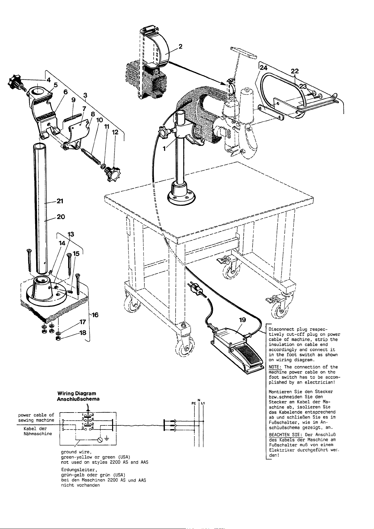
44
Page 45

PEDESTAL FOR STYLES 2200A, B, AS, AA, BA, AAS*
PEDESTAL FÜR DIE MASCHINEN 2200A, B, AS, AA, BA, AAS*
Ref. No.
Pos. No.
1*
2
3
4
5
6
7
8
9
10
11
12
13
14
15
Part No.
Teil Nr.
H1400F
2288B
A9355
1460T
1460P
1460X
96877
1460R
96854
95800
1025U
1460W
1401D
95204
95215
Description
Pedestal and Foot Switch Assembly
Leaf Spring for Thumb Switch
Machine Support Assembly
Clamp Screw
Machine Support
Rubber Pad
Pin
Clamp
Center Groved Dowel Pin
Stud
Washer
Clamp Nut
Base
Set Screw
Spot Screw
Beschreibung
Pedestal mit Fußschalter komplett
Blattfeder für Druckknopfschalter
Maschinenträger komplett
Griffschraube
Maschinenträger
Gummieinlage
Stift
Pratze
Knebelkerbstift
Bolzen
Scheibe
Griffmutter
Säulenfuß
Druckschraube
Spitzschraube
Amt. Req.
Anzahl
1
1
1
1
1
4
12
1
1
1
1
1
1
1
1
16
17
18
19
20
21*
22*
23
24
G105B
96902
95251
998-46
1403B
1403B1300
2103E
22585B
2105AC
Tables for pedestal see following pages.
* Extra order and charge item.
Screw with Nut and Washer
Washer
Nut
Foot Switch
Column 535 mm (approx. 21") long
Column 1300 mm (approx. 51") long
Bag Feed-in Guide and Finger Guard with
longer guides, preferable for styles used
stationary with pedestal.
Screw
Washer Plate
Schraube mit Mutter und Scheibe
Scheibe
Mutter
Fußschalter
Säule 535 mm lang
Säule 1300 mm lang
Sackeinführung und Fingerabweiser mit
längeren Führungen, vorzugsweise für
Maschinen, die stationär mit Pedestal verwendet werden.
Schraube
Unterlegplatte
Tische für Pedestal siehe nachfolgende Seiten.
* Gegen zusätzliche Bestellung und Berechnung.
3
1
1
1
1
1
1
2
1
45
Page 46

46
Page 47

TABLES FOR PEDESTAL MOUNTED STYLES*
TISCHE FÜR PEDESTAL MONTIERTE MASCHINEN*
Ref. No.
Pos. No.
1*
2
3
4
5
6
7*
8
9
10
11
12
13
14
15
16
Part No.
Teil Nr.
A9847B
G61371KB
90561K
A9847C
999-135D
999-136D
90709PS
G21371WY1
90710A
90711
90561G
90561G
96901Z
95322Z
96121Z
999-135A
999-136
Description
Small movable table, lenght 700 mm
(27 9/16") width 550 mm (21 5/8"), height
760 mm (30")
Table Board
Wood Screw
Frame, movable
Roller
Guide Roller, lockable
Movable Table with Roller Type Conveyor,
length 1060 mm (41 3/4"), width 550 mm (21
5/8"), height ajdustable from 860 to 970 mm
(33 7/8" - 38").
Table Board
Magnet
Roller Type Conveyor
Wood Screw for Roller Type Conveyor
Wood Screw for Table Top
Washer
Hex. Head Screw
Lock Washer
Roller
Guide Roller, lockable
Beschreibung
Kleiner fahrbarer Tisch, Länge 700 mm,
Breite 550 mm, Höhe 760 mm
Tischplatte
Holzschraube
Untergestell, fahrbar
Bockrolle
Lenkrolle, feststellbar
Fahrbarer Tisch mit Rollenrost, Länge
1060 mm, Breite 550 mm, Höhe
einstellbar von 860 bis 970 mm.
Tischplatte
Haftmagnet
Rollenrost
Holzschraube für Rollenrost
Holzschraube für Tischplatte
Scheibe
Sechskantschraube
Zahnscheibe
Bockrolle
Lenkrolle, feststellbar
Amt. Req.
Anzahl
1
1
4
1
2
2
1
1
1
1
8
4
4
8
4
2
2
17*
18
19
20
21
22
23
24
25
26
27*
28
29
30
31
90709PR
G21371WY1
90710A
90711
90561G
90561G
96901Z
95322Z
96121Z
90709PB
90709PA
A9847BS
998-94B
998-348-1
A9847D
998-246F
Table with Roller Type Conveyor, length
1060 mm (41 3/4"), width 550 mm (21 5/8"),
height adjustable from 725 to 835 mm (28
1/2" - 33 7/8").
Table Board
Magnet
Roller Type Conveyor
Wood Screw for Roller Type Conveyor
Wood Screw for Table Top
Washer
Hex. Head Screw
Lock Washer
Vibration Damper, adjustable
Vibration Damper
Small movable table, same as A9847B, but
with socket for sewing head, support for
foot switch and main switch.
Socket
Fuse 1 A
Support for foot switch (see also
pedestal and foot switch assembly
H1400F)
Main Switch
Tisch mit Rollenrost, Länge 1060 mm,
Breite 550 mm, Höhe einstellbar von
725 bis 835 mm.
Tischplatte
Haftmagnet
Rollenrost
Holzschraube für Rollenrost
Holzschraube für Tischplatte
Scheibe
Sechskantschraube
Zahnscheibe
Schwingungsdämpfer, verstellbar
Schwingungsdämpfer
Kleiner fahrbarer Tisch, wie A9847B, jedoch
mit Steckdose für Nähmaschine, Pedalträger
für Fußschalter und Wippkontrollschalter mit
Glimmlampe.
Steckdose
Sicherung 1 A
Pedalträger für Fußschalter (siehe auch
Pedestal mit Fußschalter komplett H1400F)
Wippkontrollschalter mit Klemmlampe
1
1
1
1
8
4
4
8
4
1
3
1
1
1
1
1
32*
90709PSA
33
90709PQ2
* Extra order and charge item. * Gegen zusätzliche Bestellung und Berechnung.
Movable Table with Roller Type
Conveyor, same as 90709PS but with
socket for sewing head, support for foot
switch and main switch (not shown)
Support for foot switch (not shown)
47
Fahrbarer Tisch mit Rollenrost, wie 90709PS,
jedoch Steckdose für Nähmaschine, Pedalträger für Fußschalter und Hauptschalter
(nicht abgebildet)
Pedalträger für Fußschalter (nicht abgebildet)
1
1
Page 48

TOP LOCK SPRING BALANCER FOR STYLE 2200A, B, F, AA, AS, BA, FA, AAS
FEDERZUGAUTOSTAT FÜR DIE MASCHINEN 2200A, B, F, AA, AS, BA, FA, AAS
The top lock spring balancer part No.
90191M is recommended for effortless
operation of the machines. It keepts the
suspended machine always handy and
save.
IMPORIMPOR
TT
IMPOR
IMPORIMPOR
into service read the instructions and
observe the safety rules of the supplier!
ANT! ANT!
T
ANT! Before putting the balancer
TT
ANT! ANT!
Für leichte Handhabung der Maschinen wird der
Federzugautostat Teil Nr. 90191M empfohlen. Die
am Federzug hängende Maschine ist stets griffbereit und vor Beschädigungen geschützt.
WICHTIG! WICHTIG!
WICHTIG! Lesen Sie vor Inbetriebnahme des
WICHTIG! WICHTIG!
Autostaten die Betriebsanleitung und befolgen
Sie die Sicherheitshinweise des Herstellers!
Ref. No.
Pos. No.
1*
Part No.
Teil Nr.
90191M
2
90191M1
3
2188
4
99271
5
* Extra order and charge item. * Gegen zusätzliche Bestellung und Berechnung.
Description
Top Lock Spring Balancer Assembly
Balancer
Bracker
Screw for Bracket
Instructions (not shown)
Beschreibung
Federzugautostat komplett
48
Autostat
Haltebügel
Schraube für Haltebügel
Betriebsanleitung (nicht gezeigt)
Amt. Req.
Anzahl
1
1
1
1
1
Page 49

49
Page 50

50
Page 51

THREAD STAND PART NO. 93065C
DICHTKORDELHALTER TEIL NR. 93065C
Ref. No.
Pos. No.
1
2
3
4
5
6
7
8
9
10
11
12
13
Part No.
Teil Nr.
93065C
93065CB
93065CD
93065CA
96902
95291
2289B
99270
93065CC
93B
95580
2158F
2158G
Description
Thread Stand for Filler Cord complete
Cone Support
Rod
Thread Eyelet
Washer
Nut
Spool Pin
Thumb Screw
Bracket
Screw
Screw
Thread Eyelet
Thread Eyelet for Filler Cord
Beschreibung
Dichtkordelhalter komplett
Trägerplatte für Garnrollen
Verbindungsstange
Fadenführung
Scheibe B6,4
Sechskantmutter M6
Rollenhalter mit Kugelknopf
Rändelschraube
Halter
Zylinderschraube
Linsenkopfblechschraube
Fadenführung
Fadenführung für Kordel
Amt. Req.
Anzahl
1
1
1
1
4
4
3
3
1
3
1
1
1
51
Page 52

NUMERICAL INDEX OF PARTS
AUF WELCHER SEITE FINDE ICH TEILE UND IHRE ABBILDUNGEN
Part No.
Teil Nr.
Page
Seite
1025U ... 45
109 ... 21
116 ... 43
118G ... 43
12934A ... 21, 23
1401D ... 45
1403B ... 45
1403B1300 ... 45
1460P ... 45
1460R ... 45
1460T ... 45
1460W ... 45
1460X ... 45
2101 ... 25
2103A-50 ... 27
2103A-60 ... 27
2103AA-50 ... 27
2103AA-60 ... 27
2103AB ... 27
2103AC ... 25, 27
2103E ... 45
2105 ... 23
2105AC ... 45
2108 ... 23
2108B ... 23
2115 ... 23
2120 ... 21
21201 ... 43
21202 ... 43
2121FA ... 29
2121FAN ... 29
2122 ... 25
21225-4/4,4 ... 43
21225-9/64 ... 43
2124 ... 25
2124FAN ... 29
2125 ... 23
2126 ... 21
2127B ... 25, 27
2127C ... 25, 27
2129B ... 19, 25
2129M ... 31, 33, 35, 39, 41
2129MY ... 37
2130 ... 25
2131 ... 23
2132 ... 23
2133 ... 23
2134A ... 23
2135N ... 23
2135R ... 23
2136 ... 23
2139N ... 23
2140N ... 19, 23
Part No.
Teil Nr.
2141 ... 25
2142 ... 23
2143 ... 21
2144 ... 23
2145 ... 25
2145A ... 23
2146 ... 21
2148 ... 25
2149 ... 25
2150 ... 25
2151 ... 23
2152 ... 23
2152B ... 23
2153 ... 23
2154 ... 25
2155 ... 25
2156 ... 23
2157 ... 25
2157E ... 27
2158A ... 21
2158B ... 23
2158C ... 21
2158D ... 21
2158E ... 23
2158F ... 51
2158G ... 51
2159A ... 21
2160N ... 21
2161 ... 29
2162 ... 29
2163 ... 21
2165A ... 19, 23
2165C0.5 ... 19, 23
2165D0.1 ... 19, 23
2165D0.2 ... 19, 23
2165D0.3 ... 19, 23
2165D0.5 ... 19, 23
2165D1.0 ... 19, 23
2165FAN ... 29
2166A ... 21
2167A ... 21
2168A ... 21
2169A ... 21
2170 ... 25
2170A ... 27
2171 ... 25
2172C ... 25
2173A ... 23
2175A ... 21
2176B ... 21
2176D ... 21
2177 ... 23
2178 ... 21
Page
Seite
Part No.
Teil Nr.
Page
Seite
2179 ... 21
2180 ... 21
2182 ... 25
2182A ... 25
2182B ... 25
2182C ... 25
2183 ... 25
2186 ... 21
2188 ... 27, 48
2188C ... 27
2189C ... 21
2189H ... 21
2190 ... 19
2191 ... 19, 23
2192 ... 19
2193 ... 19, 21, 23
2193A ... 19
2194 ... 19, 23
2195N ... 19, 23
2196A ... 21
2196B ... 21
2203E ... 25
22528 ... 21, 25
22542 ... 25, 27
22560B ... 23
22561 ... 25
22562 ... 27
22570A ... 27
22575 ... 23
22585 ... 25
22585A ... 21, 25, 27
22585B ... 21, 25, 45
22585R ... 27
22596 ... 23
2265 ... 31, 33
2265B ... 35, 37, 39, 41
2265C ... 31, 33, 35, 37, 39, 41
2265DA ... 31, 33, 35, 37, 39, 41
2265F ... 31, 33
22724 ... 27
22764 ... 25
22764A ... 23
22768 ... 23
22804 ... 29
22837 ... 27
22848 ... 27
22874 ... 27, 29
2288 ... 31, 33, 35, 37, 39, 41
2288B ... 45
2289B ... 21, 51
28 ... 23, 25
28C ... 21, 23
29929A ... 31
52
Page 53

NUMERICAL INDEX OF PARTS
AUF WELCHER SEITE FINDE ICH TEILE UND IHRE ABBILDUNGEN
Part No.
Teil Nr.
29929AS ... 39
29929BC ... 33
29929F ... 35
29929M ... 37
29929MB ... 41
39250J ... 27
39350J ... 23
402 ... 27
41071G ... 21, 23
51192G ... 21
51225W ... 21, 23
51292A ... 21
51292C ... 21
51292F1 ... 21
51292F8 ... 21
51758 ... 21
538 ... 25
73 ... 25
73C ... 23
76099D ... 19
77K ... 25
79 ... 21
80175 ... 21, 23
80265 ... 29
80275 ... 27
80640E ... 27
87A ... 21, 25
87U ... 21, 25, 27
88 ... 25
88B ... 23
88D ... 29
90191M ... 48
90191M1 ... 48
90195 ... 41
90195B ... 41
90195C ... 41
90233A ... 39, 41
90233B ... 31
90233BA ... 33
90233F ... 35, 37
90561G ... 47
90561K ... 47
907 ... 21
90709PA ... 47
90709PB ... 47
90709PQ2 ... 47
90709PR ... 47
90709PS ... 47
90709PSA ... 47
90710A ... 47
90711 ... 47
93 ... 21, 27
93065C ... 51
93065CA ... 51
Page
Seite
Part No.
Teil Nr.
Page
Seite
93065CB ... 51
93065CC ... 51
93065CD ... 51
93077 ... 27
93077A ... 27
93077B ... 27
93077C ... 27
93077D ... 27
93077E ... 27
93640 ... 21
93B ... 21, 51
94 ... 27
95182V ... 31, 33
95204 ... 45
95215 ... 45
95251 ... 45
95257 ... 31, 33, 35, 37, 39, 41
95291 ... 51
95322Z ... 47
95515 ... 31, 33, 35, 37, 39, 41
95580 ... 21, 31, 33, 35, 37, 39, 41, 51
95581 ... 31, 33, 35, 37, 39, 41
95601 ... 43
95606 ... 43
95626 ... 43
95665 ... 31, 33, 35, 37, 39, 41
95800 ... 45
95954 ... 21
96121Z ... 47
96256 ... 25, 29
96501 ... 23
96502 ... 23
96511 ... 19
96523 ... 19
96602 ... 23
96603 ... 23
96650 ... 25, 27
96663 ... 21
96701 ... 27
96854 ... 45
96877 ... 45
96901Z ... 47
96902 ... 45, 51
9854G-Div. ... 43
99266 ... 19
99266A ... 19
99267 ... 23
99268 ... 21
99269 ... 25, 27
99270 ... 21, 51
99271 ... 27, 31, 33, 35, 37, 39, 41, 48
99277 ... 23
9937 ... 27
99373 ... 25
Part No.
Teil Nr.
Page
Seite
995-504 ... 29
995-506A ... 31, 33, 35, 37, 39, 41
995-518A ... 31, 33, 39
995-518F ... 35
995-518YA ... 37
995-518YY ... 41
995-523 ... 31, 35, 39
995-524 ... 31, 33, 35, 39, 41
99521 ... 23
99555 ... 27
99556 ... 27
99557 ... 27
99558 ... 27
99559 ... 27
99560 ... 27
99654B ... 31, 33, 35, 37, 39, 41
997A502N ... 31, 39
997AE3D502N ... 31
997BC502 ... 33
997F502 ... 35
997Y502 ... 37
997YY502 ... 41
998-20B ... 31, 33, 35, 37, 39, 41
998-20BA ... 31, 33, 35, 37, 39, 41
998-20BB ... 31
998-246F ... 47
998-266A ... 35
998-348-1 ... 47
998-416 ... 31, 33, 35, 37, 39, 41
998-416L ... 31
998-46 ... 45
998-94B ... 47
998A61A ... 43
999-104A ... 19
999-117 ... 43
999-135A ... 47
999-135D ... 47
999-136 ... 47
999-136D ... 47
999-233 ... 31, 33, 35, 37, 39, 41
999-311 ... 29
A9355 ... 45
A9847B ... 47
A9847BS ... 47
A9847C ... 47
A9847D ... 47
B660-210 ... 23
53
Page 54

NUMERICAL INDEX OF PARTS
AUF WELCHER SEITE FINDE ICH TEILE UND IHRE ABBILDUNGEN
Part No.
Teil Nr.
C55 ... 33
G10349 ... 25
G105B ... 45
G2127 ... 25, 27
G2127A ... 25, 27
G21371WY1 ... 47
G22585A ... 21
G28604L ... 43
G28604L5 ... 43
G29486E ... 27
G29490 ... 25
G29492 ... 23
G29493B ... 21
G29496 ... 21
G29497 ... 25
G29497A ... 27
G29901A50 ... 27
G29901A60 ... 27
G41041B ... 27
G41046G ... 19
G43266 ... 21
G43294B ... 43
G61371KB ... 47
G660-210 ... 23
Page
Seite
Part No.
Teil Nr.
Page
Seite
Part No.
Teil Nr.
Page
Seite
H1400F ... 45
HA61D ... 23
J118B ... 43
J1614 ... 25, 27
M129VC ... 35
M129VDE ... 33
M129VF ... 39, 41
M129VG ... 31
M129VH ... 37
54
Page 55

NOTESNOTES
NOTES
NOTESNOTES
NOTIZENNOTIZEN
NOTIZEN
NOTIZENNOTIZEN
55
Page 56

WORLDWIDE SALES AND SERVICE
WELTWEITER VERKAUF UND KUNDENDIENST
Union Special maintains sales and service facilities throughout the
world. These offices will aid you in the selection of the right sewing
equipment for your particular operation. Union Special representatives and service technicians are factory trained and are able to
serve your needs promptly and efficiently. Whatever your location,
there is a qualified representative to serve you.
Corporate
Office:
European Distribution Center:
Union Special unterhält Verkaufs- und Kundendienst-Niederlassungen in der ganzen Welt. Diese helfen Ihnen in der Auswahl der
richtigen Maschine für Ihren speziellen Bedarf. Union Special
Vertreter und Kundendiensttechniker sind in unseren Werken
ausgebildet worden, um Sie schnell und fachmännisch zu bedienen.
Union Special Corporation
One Union Special Plaza
Huntley, IL 60142
Phone: US: 800-344 9698
Phone: 847-669 4200
Fax: 847-669 4355
e-mail: bags@unionspecial.com
www.unionspecial.com
Union Special GmbH
Raiffeisenstrasse 3
D-71696 Möglingen, Germany
Tel.: 49 (0)7141/247-0
Fax: 49(0)7141/247-100
e-mail: sales@unionspecial.de
www.unionspecial.de
 Loading...