

Page 1
FINEST
CLASS
2100
QUALITY
LEWI
INDUSTRIAL
SEWING
MACHINES
S
COLUMB
IA
CATALOG
No.
TRAGBAREEIN-UND
ZWEIFADEN
227
VmimSpedjoi.
SACKZUNAHMASCHINE
MAScniNENFASRiKfi
stuttgartw
PORTABLE
ELECTRIC
CLOSING
SCHWABSTRASSE
BAG
MACHINE
33
Page 2
ADJUSTING
CATALOG
No.
227
INSTRUCTIONS
FOR
AND
OPERATING
The
parts
furnished
at
list
LIST
OF
CLASS
2100
listed
prices
in
PARTS
this
for
catalog
repairs
are
only.
UmmSpecidL
maschinenfabrikim
Printed
by
stuhgart-w
Edition - April
schwabstrassess
1967
Page 3
fUr
UNION
MaschinenbeachrBihiin^
Ersatateile
SPECIAL
j:;
ri:
-
Katalog
Handsackzunahmaachinen
tmd
Einstellanleitunf^
der
Klaasen
2100
—3
NEhart
Stich-lVpe
Stichlange 3 - 9 mm
Ober—
Zahnieilung
NShkapaaitSt
01;
Nadel-Type
PUr
Nadel-Type
Lieferbare
Klingen-0
"
temporaturm'lirnmu'tin^ToractoUrM^de"Nadel''°ertlndeit''D°''
von
SSa-1
101
Einfachkettenstich
u.
Untertransport
2,1
mm
bia 9 mm
Mobil
D.T.E.
EunststoffsEcke:
NadelatErken
in^
KunataboPPadckan
Oil
9854
9857 T NormalatErke
oder
Stoffatarke,
Medium
NormalstErke
049
. 1 ,24 1 ,70
od.r
080
080
067
401
bia
080
QQO
2,03
2,29
Doppelkettenstich
24
Lagan
Papiar
in
-
-
—n
^'3
''3''3
100
ohne
Wlderatand
N«r
"CNION
dirch°L"NSdolSb/|leiteI°™U?°''^°''
SPECIdt.
.
Nadaln
Nadeln
ge.dbrl,xat,o
Type
9854 - 080
®3''°3t®3k«.
aln
ainvandfraiaa
drb.itan
'"Lai
an
unaarar
"-'3^33aiebnnng.
beaahtan
iat,
daS
daa
Maaabinan.
Sam
Page 4
Parts - Catalog
for
mUNION
SPECIAL"
and
adjusting
portable
instruction
bag-closer
class
2100
Descrintion
For
closing
vith
single-thread
The
machine
type
electric-motor
multi-vane
The
machines
and
stop.
Seam
Specification
Stitch
Stitch
Top
Teeth
Seving
Oil:
Needle
For
Type
length 3 to 8 1/2
and
bottom
cut
capacity:
Mobil
Type
bags
made
of
machine
bags
of
is
equipped
motor.
vith
101
single
feed
12
per
3/8"
D.T.E.
9834 - 080
of
plastic
different
chain
stitch
vith
to
operate
electric
SSa-1
thread
per
inch
for
fabric
Oil
Medium
material:
size
(type
top
on
motor
chain
inch
made
101)
and
bottom
single
can
also
stitch
bags
or
of
cotton,
or
feed,
phase
be
or
24
plies
ordered
jute,
tvo-thread
mechanically
alternating
vith a feeler
401
tvo-thread
of
paper
multivall
chainstitch
paper
(type
operated
current
or
controlled
chain
stitch
and
401).
chain
direct
plastic
material
cutting
current,
svitch,
device
or
air
for
automatic
(polyethylene)
and
iiniversal
operated
start
Needle
The
Size
Size
Needle
and
Needle
Type
folloving
(inch)
(mm)
Type
paper
bags
type
especially
your
machine-order.
Each
UNION
shank.
To
should
A
Selection
through
Success
Collectively,
have
needle
be
complete
needle
in
given.
of
9857 T -
sizes
049
1,24
9854
and
9857 T has a round
used
SPECIAL
orders
order
proper
eye
the
operation
080
of
needles
067
1,70
has a square
standard
for
closing
needle
See
vould
in
type
promtly
marks
read:
needle
order
of
has
number
080
2,03
on
size
are
available:
090
2,29
point
in
plastic
100
to
this
and a nickel
the
machines.
point
sharp
bags
the
name
and
size
and
accurately
packages.
needles
should
produce a good
machine
plated
tip
and a lo-temp
(polyethylene).
"UNION
be
SPECIAL", a type
number
filled,
Type
9854.
determined
stitch
can
be
secured
represent
the
size
by
formation.
finish.
finish
If
this
the
empty
080
size
of
only
vith
This
needle
that
needle
number,
complete
package,
thread
the
genuine
is
used
inhibits
is
requested
and a size
symbol.
or
the
type
used.
Thread
UNION
for
heat.
please
number
and
should
SPECIAL
closing
This
needle
specify
stamped
size
numbers
pass
needles.
jute-
is
on
on
the
freely
Page 5
2100
2100
2100
2100
2100
2100
2100
2100
Aufstelluns
A
Doppelkettenstich,
B
Doppelkettenstich,
C
Doppelkettenstich,
D
Doppelkettenstich,
E
Doppelkettenstich,
F
Doppelkettenstich,
K
Doppelkettenstich,
L
Doppelkettenstich,
der
verschiedenen
Motor
fUr
Motor
fUr
Motor
fUr
Motor
fUr
Motor
fur
Motor
fUr
Motor
fUr
Luftmotor
Mascbinen
...
220
110-125
220-240
110-125
....
50
....
42
...
240
Klassen
Volt,
Volt,
Volt,
Volt,
Volt,
Volt,
Volt,
50
Perioden
60
Perioden
60
Perioden
50
Perioden
50
Perioden
50
Perioden
50
Perioden
2100
AT
2100
BT
2100
CT
2100
DT
2100
ET
2100
FT
2100
KT
2100
AA
2100
BA
2100
OA
2100
DA
2100
EA
2100
FA
2100
KA
2100
LA
2100
AAT
2100
BAT
2100
CAT
2100
DAT
2100
EAT
2100
FAT
2100
KAT
Alle
Maschinen
Jede
Doppelkettenstich-Maschine
Dazu
verden
verden
folgende
1 Teil
1
Teil
1
Teil
1 Teil
1
Teil
1 Teil
entsprechend
Teile
Nr.
Nr.
Nr.
Nr.
Nr.
Nr.
vie
vie
vie
vie
vie
vie
vie
Klasse
Klasse
Klasse
Klasse
Klasse
Klasse
Klasse
2100
2100
2100
2100
2100
2100
2100
A,
B,
C,
D,
E,
F,
K,
Einfachkettenstich,
Einfachkettenstich,
Einfachkettenstich,
Einfachkettenstich,
Einfachkettenstich,
Einfachkettenstich,
Einfachkettenstich,
Einfachkettenstich,
vie
vie
vie
vie
vie
vie
vie
Klasse
Klasse
Klasse
Klasse
Klasse
Klasse
Klasse
der
2100
2100
2100
2100
2100
2100
2100
der
deutschen
Klasse
AA,
BA,
OA,
DA,
EA,
PA,
KA,
2100
benotigt:
2108
A
Greifer
2111
28
22585
39236
51758
stichgreifer
Schleifenhalter ) Diese
Schraube
A
Schraube
A
Scheibe
Nadelfadenfiihrung
Jedoch
jedoch
jedoch
jedoch
jedoch
jedoch
jedoch
Motor
Motor
Motor
Motor
Motor
Motor
Motor
Luftmotor
jedoch
jedoch
jedoch
jedoch
jedoch
jedoch rait
jedoch
mit
mit
mit
mit
mit
mit
mit
fUr
fUr
fUr
fUr
flir
fUr
fUr
mit
mit
mit
mit
mit
mit
VDE — Norm
kann
auf
flir
Einfachkettenstich
2108
f.
2111 ) der
f.51758
f.
22585
A
Tasterschaltung
Tasterschaltung
Tasterschaltung
Tasterschaltung
Tasterschaltung
Tasterschaltung
Tasterschaltung
...
220
Volt,
50
110-125
220-240
110-125
....
....
...
Tasterschaltung
Tasterschaltung
Tasterschaltung
Tasterschaltung
Tasterschaltung
Tasterschaltung
Tasterschaltung
50
42
240
Volt,
Volt,
Volt,
Volt,
Volt,
Volt,
geliefert
60
60
50
50
50
50
und
Perioden
Perioden
Perioden
Perioden
Perioden
Perioden
Perioden
sind
Einfachkettenstich
zum
Austausch
Teile
Stichplatte
verden
geschraubt.
funk—u.fernsehentstort.
umgebaut
auf
gegen
die
Unterseite
verden.
Doppelketten-
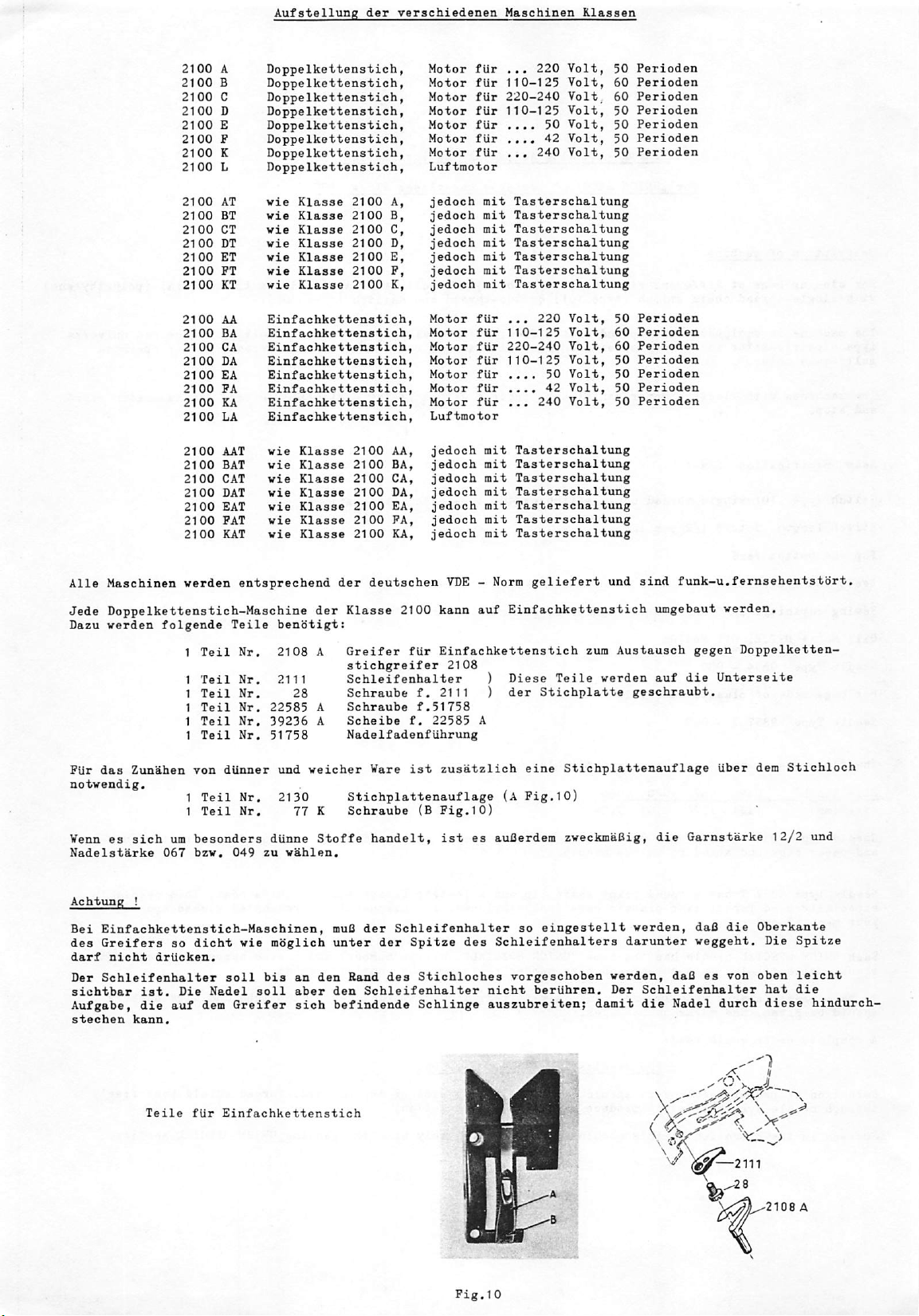
FUr
das
notvendig.
Zunahen
Venn
es
Nadelstarke
Achtung
Bei
des
darf
Der
sichtbar
Aufgabe,
stechen
sich
!
Einfachkettenstich-Haschinen,
Greifers
nicht
Schleifenhalter
ist.
die
kann.
Teile
von
1 Teil
1
urn
besonders
067
bzv.
so
dicht
drlicken.
Die
auf
flir
dUnner
Nr.
Teil
Nr.
049
zu
vie
soil
Nadel
dem
bis
soil
Greifer
Einfachkettenstich
und
veicher
2130
Stichplattenauflage
77 K Schraube
dunne
Stoffe
vahlen.
muQ
mbglich
unter
an
den
aber
den
sich
befindende
Rand
Vare
ist
zusatzlich
(B
Pig.10)
handelt,
der
der
des
Schleifenhalter
ist
Schleifenhalter
Spitze
des
Stichloches
Schlinge
eine
Stichplattenauflage
(A
Fig.10)
es
auGerdem
zveckmaSig,
so
eingestellt
Schleifenhalters
vorgeschoben
nicht
beriihren,
auszubreiten;
verden,
darunter
verden,
Der
Schleifenhalter
damit
die
die
Garnstarke
daO
veggeht.
daO
es
Nadel
.-"OV
liber
die
von
durch
—2111
dem
Stichloch
12/2
und
Oberkante
Die
Spitze
oben
leicht
hat
die
diese
hindurch-
2108
A
Pig.10
Page 6
STYLES
OP
MACHINES
IN
CLASS
2100
2100
2100
2100
2100
2100
2100
2100
2100
2100
2100
2100
2100
2100
2100
2100
2100
2100
2100
2100
2100
2100
2100
2100
2100
2100
2100
2100
2100
2100
2100
A
Two
B
C
D
E
F
K
L
AT
BT
CT
DT
ET
FT
KT
AA
BA
CA
DA
EA
FA
KA
LA
AAT
BAT
CAT
DAT
EAT
FAT
KAT
thread
Two
thread
Tvo
thread
Two
thread
Two
thread
Two
thread
Two
thread
Two
thread
Same
as
Same
as
Same
as
Same
as
Same
as
Same
as
Same
as
Single-thread
Single-thread
Single-thread
Single-thread
Single-thread chain
Single-thread chain
Single-thread
Single-thread
Same
as
Same
as
Same
as
Same
as
Same
as
Same
as
Same
as
chain
chain
chain
chain
chain
chain
chain
chain
Style
Style
Style
Style
Style
Style
Style
Style
Style
Style
Style
Style
Style
Style
stitch
stitch
stitch
stitch
stitch
stitch
stitch
stitch
2100
2100
2100
2100
2100
2100
2100
chain
chain
chain
chain
chain
chain
2100
2100
2100
2100
2100
2100
2100
A
B
C
D
E
F
K
stitch
stitch
stitch
stitch
stitch
stitch
stitch
stitch
AA
BA
CA
DA
EA
PA
KA
with
with
with
with
with
with
with
with
Except
and
stop
vith
with
with
with
with
with
with
with
Except
and
stop
motor
motor
motor
motor.
motor
motor.
motor
air
operated
feeler
controlled
mechanism
motor
motor
motor
motor
motor.....
motor
motor
air
operated
feeler
controlled
mechanism
multi-vane
start
multi-vane
start
Volt
. 110-125
.
220-240
. 110-125
motor
220
110-125
220-240
110-125
240
motor
240
42
50
50
Cycles
50
60
60
50
50
50
50
All
machines
is
eliminated.
Every
For
this
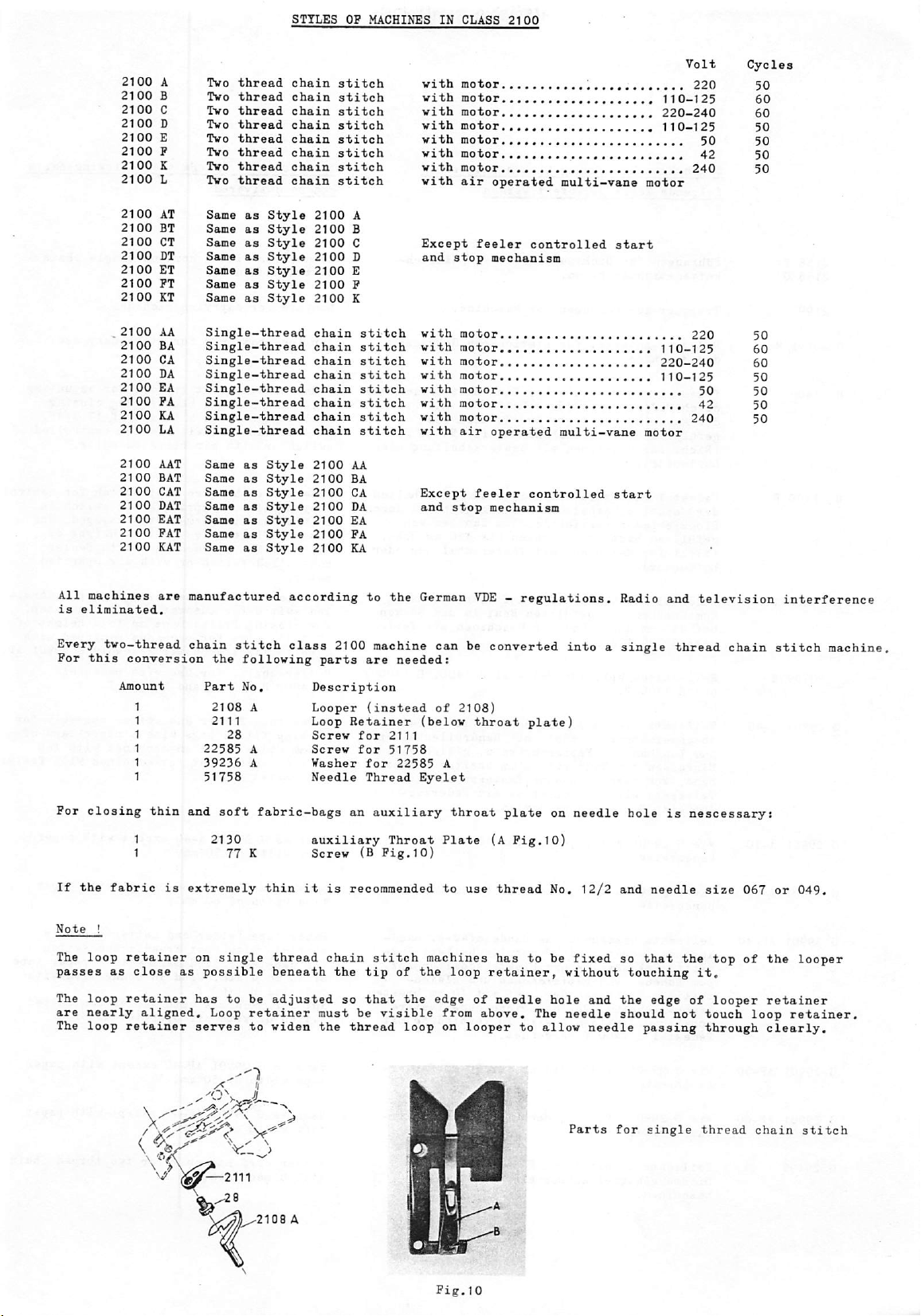
For
closing
If
the
Note
!
The
loop
passes
The
loop
are
nearly
The
loop
are
manufactured
two-thread
chain
conversion
Amount
thin
and
1
1
fabric
is
extremely
retainer
as
close
as
retainer
aligned.
retainer
stitch
the
following
Part
No,
2108
2111
28
22585
39236
51758
soft
2130
77
on
single
possible
has
to
Loop
serves
according
class
parts
Description
A
Looper
Loop
A
A
Screw
Screw
Washer
Needle
fabric-bags
auxiliary
K
thin
thread
Screw
it
is
chain
beneath
be
adjusted
retainer
to
widen
must
the
to
the
2100
machine
are
needed:
(instead
Retainer
for
2111
for
51758
for
22585
Thread
an
auxiliary
Throat
(B
Fig.10)
recommended
stitch
the
tip
of
so
that
be
visible
thread
German
can
of
(below
A
Eyelet
Plate
to
machines
the
the
edge
from
loop
on
VDE - regulations.
be
converted
2108)
throat
throat
(A
use
loop
retainer,
of
above.
looper
plate
Fig.10)
thread
has
needle
to
into a single
plate!
on
No.
to
be
without
hole
The
needle
allow
Radio
needle
12/2
and
fixed
so
and
the
should
needle
and
thread
hole
is
needle
that
the
touching
edge
not
passing
television
chain
nescessary:
size
067
top
of
it.
of
looper
touch
through
the
retainer
loop
clearly.
interference
stitch
or
machine.
049.
looper
retainer.
^"1
Parts
^^3^^2111
2108
A
Pig.10
for
single
thread
chain
stitch
Page 7
Gegen
Extraberechnung
folgende
Teile
kHnnen
geliefert
verden
zuaatzlich
Against
can
be
extra
delivered
charge
the
following
parts
2158
2158
2199
G
20191
H 1400
H 1400
H 1400
90709
P
G
Piihrungen
kettenstichmaschinen.
TragguT't
M
Pederzug—Autos'ta'b
der
Pedestal
durch
der
?efullten
Nicht
Luftmotor).
P
T
R
Pedestal
der
Blockierfeder
gefiillten
(Nicht
Luftmotor).
Pedestal
Zum
bei
satz G 29901
Rollentisch
und H 1400
fur
zuo
Umhangen.
Maschine.
mit
PuOtritt
Maschine
mechanischer
bethtigt.
Beuteln
fUr
Maschinen
mit
Maschine.
Zundhen
450
Mikrofuflschalter
Beuteln
fUr
Maschinen
fUr
Maschinen
von
mm
Hbhe.
AP.
kpl.
T.
Dichtungskordel
der
fiir
s'ta'tiondren
die
den
Schalter
Zum
und
Sacken
mit
Schalter
verriegelt.
im
u,
S'dcken
mit
gefiillten
mit
Und
fUr
fiir
Pedestal H 1400, H 1400
fUr
Maschine.
Einschaltvorrichtung
Zunahen
bis
Tastersehaltung
Handgriff
Zum
bis
Tasterschaltung
Tasterschaltung,
Beuteln
Maschinen
Einfach-
Gebrauch
im
Handgriff
von
450
z\un
Einschalten
wird
Zunahen
450
mm
und
mit
mm
HShe.
oder
durch
von
Hbhe.
oder
Shcken
Teile-
Guides
stitch
Lanyard
Top
Pedestal
switch
filled
Not
switch
Pedestal
ling
machine
closing
17
controlled
motor.
Pedestal
led
For
17
tape
Roller-shelf,
P
for
machines.
lock
in
bags
for
or
Filter
for
balancer
with
machine
machines
with
with
cord
carrying
for
foot
treadle
handle.
up
to a height
with
air
operated
micro
foot
on
machine.
stationary
feeler
machine. A spring
handle
filled
3/4".
switch
closing
3/4".
folder
H
1400, H 1400 P and H 1400
Not
switch
for
for
filled
Also
and
for
machines
permanently
bags
up
machines
or
with
automatic,
with
bags
for
machines
cutter
for
use
with
single
For
switch
keeps
to a height
with
air
start
up
chain
use.
for
actuating
closing
of
17
3/4",
controlled
motor.
for
switch
engaged.
control
in
For
of
feeler
operated
feeler
and
control
stop.
to a height
equipped
with
of
assembly G 29901
pedestals
T.
AP,
G
G
G
G
G
G
G
29901
29901
29901
29901
29901
29901
29499
A-40
A-50
A-60
AP-40
AP-50
AP-60
Teilesatz
abschneidapparat
Zum
Einfassen
band.
Teilesatz
Autostat G 20191 M verwendet.
Vie G 29901
bandbreite.
Vie G 29901
bandbreite.
Teilesatz
abschneidapparat
tritt,
Zum
zeitigem
Kreppapierband,
schaltung,
Pedestal H 1400 T verwendet.
Vie G 29901
bandbreite
Vie G 29901
bandbreite.
Teilesatz
Dichtungskordel
maschinen.
bestehend
Zimdhen
der
PUr
Maschinen
wird
von
A-40,
A-40,
bestehend
Umlenkrolle
Zundhen
von
Einfassen
Teilesatz
AP-40,
AP-40,
komplett
aus
kompl,
BandeinfaB-u,
mit
Papiersdcken
Naht
mit
40
ohne
vorzugsweise
jedoch
jedoch
mit
Tasterschaltung.
fUr
fUr
aus
BandeinfaB-u.
Bandrollenhalter,
und
Elektroschalter
Papiersdcken
der
Piir
Naht
Maschinen
wird
jedoch
jedoch
zum
an
Einnahen
Doppelkettenstich—
Bandrollenhalter,
Band-
u,
gleichzeitigem
mm
breitem
mit
50
60
Kreppapier-
Pederzug-
mm
Papier-
mm
Papier-
Band-
FuB—
kpl,
und
gleich
mit
40
mm
Taster
mm
mm
einer
breitem
mit
Papier-
Papier-
ohne
in
Verbindung
fiir
50
fiir
60
Paper
tape
closing
40
mm
lock
controlled
Same
tape
Same
tape
Paper
complete
for
closing
of
40
folder
filled
width.
balancer.
as G 29901
width
as G 29901
width
tape
Used
switch.
of
of
folder
with
filled
mm
width.
pedestal H 1400
Not
for
switch
Same
tape
Same
tape
Filter
stitch
machines
or
with
as G 29901
width
of
as G 29901
width
of
cord
assembly
machines.
and
bags
with a paper
on
Not
for
A-40
50
mm.
A-60
60
mm.
and
foot
treadle
bags
Used
T.
with
air
operated
AP-40
50
mm.
AP-40
60
mm.
cutter
machines
except
except
cutter
assembly
with
machines
with
with
assembly
and
with a paper
in
connection
feeler
except
except
for
controlled
motor.
with
with
two
thread
tape
top
with
paper
paper
switch
with
paper
paper
chain
for
of
feeler
tape
Page 8
Anleitung
UNION
zur
SPECIAL
Inbetriebnahme
Maschinenklasse
der
2100
GENERAL
UNION
OPERATING
SPECIAL
INSTRUCTION
MACHINES
CLASS
2100
Einfadel-
Anleitung
Zchg.
Nr.
und
Oelanleitung
zum
An—
tmd
23292-2
Greifereinstell-Lehre
Drehrichtung
23292-2
Elektro-Antrieb
Die
Klasse
Motor,
strom
verwendet
es
unbedingt
spannung,
zahl
anzugeben.
Vor
Inbetriebnahme
werden,
entnommen
senen
Erdkontakt
so
kbnnen
Die
Kohlebiirsten
500
Betriebsstunden
erneuert
teil
der
Um
einwandfrei
empfehlen
der
2100
der
fiir
erforderlich,
und
daB
die
wird,
Unfklle
werden.
BUrsten
wir,
Maschine
hat
einen
Einphasen-Vechselstrom
werden
bei
Vechselstrom
der
Steckdose,
einen
hat.
vorkommen.
des
Motors
Uberpriift,
Auf
keinen
auf
dem
passende
diese
von
Zchg.
Abbau
des
Nr.
Motors
21225 - 4 + 0,4
siehe
Zeichnungs
eingebauten
kann.
Bei
Bestellung
die
vorhandene
auch
Maschine
auch
Ist
muB
von
der der
wirklich
dies
nicht
sollten
und
zu
zu
beziehen.
wenn
darf
schleifen.
erhalten,
Fall
Kollektor
BUrsten
uns
23221-1
Nr,
Allstrom-
und
Gleich-
ist
Strom-
die
Ferioden-
beachtet
Strom
angeschlos-
der
Fall,
nach
jeweils
nbtig,
der
Metall-
Threading
Instruction
Drawing
Looper
Operating direction
23292-2
Electrical
Your
which
nating
Before
wall
When
sary
The
carbon
500
hours
sary.
brushes
In
order
recommended
and
Oiling
for
Assembling
No.
23292-2
gauge
21225 - 4 + 0,4
Equipment
machine
can
or
is
be
used
direct
equipped
operating
socket
or
receptacle
ordering a machine
electrical
In
any
is
to
brushes
of
operation
case
not
allowed
get
to
order
details
suitable
Diagram
of
on
either
current.
the
machine,
should
the
metal
them
Drawing
Motor
to
Machine
the
machine
see
with a universal
is
please
as
voltage
be
and
renewed
to
contact
carbon
from
single
part
phase
make
sure
properly
specify
and
checked
if
of
the
the
brushes
our
branches.
No.
23221-1
Drawing
motor
alter
that
grounded.
the
neces
periods.
after
each
it
is
neces
carbon
commutator.
it
is
No.
the
Schalterbetatigung
Die
Maschine
druck
auf
gesetzt.
gedrUckt,
Einfkdeln
Das
Einfadeln
wird
die
Schaltfeder
Vird
diese
so
schaltet
der
Maschine
der
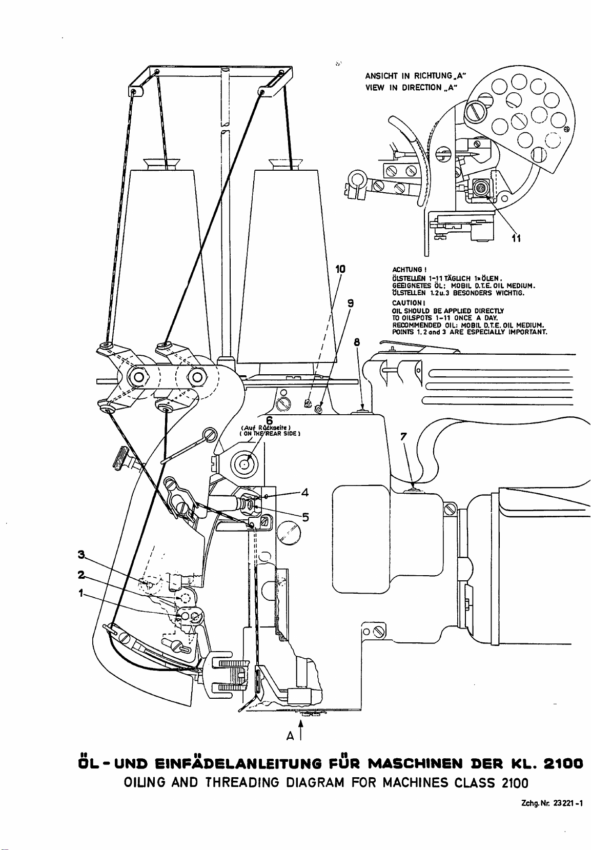
fadelanleitung
Das
EinfUhren
Nadel
wird
die
beigegebene
wird.
FUr
empfehlen
Schmieriing
Das
Clen
Tropfen
Betrieb
Olanleitung
wesentlich
die
wir
der
Maschine
01
taglich
zu
halten.
Zeichnung
des
Einfadelung
den
durch
einen
am
Feder
nicht
die
Maschine
Maschine
Zeichnung
Fadens
Pinzette
Einfadler J 118
Nr.
in
erleichtert,
Nr.
des
ist
sehr
genUgen,
Die
Olstellen
Nr.
23221-1
leichten
Handgriff
mehr
nieder-
aus.
wird
in
der
23221-1
gezeigt.
FadenfUhrung
wenn
118 B benUtzt
Greifers
B.
einfach.
um
die
Maschine in
sind
in
ersichtlich.
Daumen-
in
Gang
Ein-
und
dazu
Einige
der
Operation
A
slight
handle
pressure
Threading
For
in
Using
and
use
Oiling
Oiling
applied
sufficient
The
in
will
your
Threading
tweezers
needle,
threading
of
to
location
the
diagram
pressure
will
reference,
the
the
to
on
start
the
stop
and
Oiling
No.
will
be
wire J 118
machine
various
insure
of
the
No.
the
thumb
machine.
it.
the
threading
Diagram
118 B for
helpful.
B.
is
very
oiling
proper
oiling
23221-1.
points
switch
on
Releasing
is
illustrated
Drawing
threading
For
threading
simple. A few
points
lubrication-.
daily
is
illustrated
the
motor
the
No.23221-1
eyelets
looper
drops
will
be
Page 9
Justieranleitun
Sollte
eines
teile
es
Bruches
auszuvechseln,
veisungen
erleiehtern.
im
Falle
einer
notvendig
die
erforderlichen
so
sein
verden
normalen
einzelne
die
Einstellungen
Abniitzung
Mascbinen-
folgenden
oder
An-
Adiustins
Should
wear
it
or
machine,
making
the
Instructions
ever
become
breakage,
the
following
necessary
necessary,
to
replace
instructions
adjustments.
any
through
parts
will
normal
of
the
aid
in
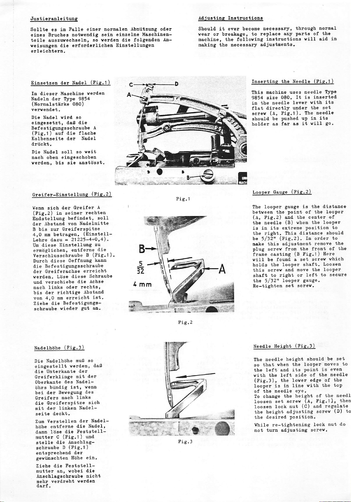
Einsetzen
In
dieaer
Nadeln
(Normalstarke
verwendet.
Die
eingesetzt,
Befestigungsschraube
(Fig.1)
Kolbenseite
driickt.
Die
nach
verden,
Greifer-Einstellung
¥enn
(Pig,2)
Endstellung
der
B
bis
4,0 ram
Lehre
Um
diese
ermbglicben,
der
Nadel
(Fig.1
der
Maschine
Type
verden
9854
080)
Nadel
vird
so
daQ
die
auf
die
flache
der
Nadel
Nadel
soil
so
oben
bis
sicb
in
eingescboben
der
seiner
sie
Greifer
veit
anstbsst,
(Pig.2!
rechten
befindet,
Abstand
von
zur
Greiferspitze
betragen.
Nadelmitte
(Einstell-
dazu = 21225-4+0,4),
Einstellung
entferne
A
A
soil
zu
die
Verschlusschraube B (Pig,l).
Durch
diese
Lose
oder
richtige
mm
erreicbt
die
Befestigungs
vieder
Oeffnung
diese
die
Befestigungsschraube
der
Greiferachse
verden.
und
verschiebe
nach
links
bis
der
Ton
4,0
Ziehe
schraube
erreicbt
die
recbts,
Abstand
gut
kann
Schraube
Achse
ist,
an.
32
U
mm
Inserting
This
9854
in
the
flat
screw
should
bolder
Looper
The
between
(a.
the
is
in
the
be
5/32"
make
plug
frame
will
holds
V
this
shaft
the
Re-tighten
the
machine
size
080,
needle
directly
(a,
Pig.l).
be
pushed
as
far
Gauge
looper
the
Pig.2)
needle
its
extreme
right.
(Fig.2).
this
adjustment
screw
casting
be
found a set
the
looper
screw
to
right
5/32"
looper
Needle
uses
lever
under
as
(Pig.2.
gauge
point
and
(B)
This
from
(B
and
set
(Pig.l
needle
It
is
inserted
with
the
The
up
in
it
will
is
the
of
the
the
center
when
the
position
distance
In
order
remove
the
front
Pig.l)
screw
shaft.
move
the
or
left
gauge.
screw.
Type
its
set
needle
its
go.
distance
looper
of
looper
should
of
Here
which
Loosen
looper
to
secure
to
to
the
the
Nadelhohe
Die
eingestellt
die
Greiferklinge
Oberkante
bhrs
bei
Greifers
die
mit
seite
Zum
hbhe
dann
mutter C (Pig.l)
stelle
(Pig.3
Nadelhbhe
muB
verden,
Unterkante
biindig
der
Bewegung
des
nach
der
mit
Nadel-
ist,
links
Greiferspitze
der
linken
deckt.
Verstellen
entferne
lose
die
Nadel-
der
die
die
Feststell—
Anscblag-
so
der
venn
des
sich
Nadel,
und
daB
Nadel
• I I
1-1—m—
••
—W
Vw
ifciiim
W- , v
schraube D (Pig.l)
entaprecbend
gevUnscbten
Ziehe
die
mutter
Anschlagschraube
mehr
verdrebt
darf.
an,
der
Hbhe
Peststell-
vobei
verden
ein.
die
nicbt
Needle
The
so
the
with
Height
needle
that
left
the
(Pig.3),
looper
of
To
loosen
loosen
the
the
¥hile
not
is
the
needle
change
set
lock
height
desired
re-tightening
turn
(Pig.3!
height
when
the
and
its
left
side
the
lower
in
line
eye.
the
height
screw
nut
adjusting
position.
adjusting
should
looper
point
of
edge
with
(A,
(C)
screw.
be
moves
is
even
the
needle
of
the
of
the
Pig.l),
and
regulate
screw
lock
nut
set
to
the
top
needl
then
(D)
do
to
Page 10
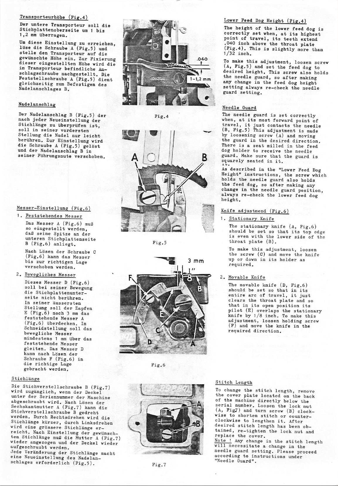
TransporteurhShe
Der
untere
StichplatteiLobeTsei'te
1
f2
mm
iiberragen.
Um
diese
lose
stelle
EinsteXlung
die
Schraube A (Pig.5)
den
gewUnschte
dieser
im
eingeatellten
Transporteur
schlagschraube
Peststellschraube A (Pig.5)
gleichzeitig
Nadelanschlages
(Pig.4'
Transporteur
um t bis
zu
Transporteur
Hbhe
ein.
Zur
Hohe
befindliche
nachgestellt.
zum
Befeatigen
B.
soli
erreichen,
auf
Pixierung
wird
die
imd
die
die
An-
Die
dient
des
Lover
Peed
Dog
Height
The
height
correctly
point
.040
inch
(Pig,4).
1/32
inch.
To
make
(a,
Pig.5)
desired
the
mm
needle
any
change
setting
guard
of
set
of
travel,
above
This
this
and
height.
guard,
in
always
setting.
the
vhen,
is
adjustment,
set
the
re-check
(Pig.4!
lover
at
its
its
teeth
the
throat
slightly
the
screv
so
after
feed
feed
dog
the
This
feed
highest
extend
plate
more
loosen
dog
also
making
height
needle
dog
than
screv
to
holds
is
Nadelanschlag
Der
Nadelanschlag B (Pig.5)
nach
jeder
Stichlange
soli
Stellung
beriihren.
die
Schraube A (Pig.5)
und
der
seiner
Messer-Einstellung
1 . Peststehendes
Das
so
daC
unteren
B
(Pig.6)
Nach
(Fig.6)
bis
verschoben
2.
Bevegliches
Dieses
soil
die
seite
In
Stellung
E
(Pig.6)
feststehende
(Pig.
Schneidstellung
bevegliche
mindestens 1 mm
feststehende
gleiten.
kann
Schraube P (Pig,6)
die
gebracht
Neueinstellung
zu
in
Nadelanschlag B in
Puhrungsnute
UberprUfen
seiner
die
Nadel
Zur
Einstellung
vordersten
Messer
Messer A (Pig,6)
eingestellt
seine
Spitze
Stichplattenseite
anliegt.
Lbsen
der
kann
zur
richtigen
Messer D (Pig.6)
bei
Schraube
das
verden.
Messer
seiner
Stichplattenunter-
nicht
seiner
beriihren.
aussersten
soil
der
noch 3 mm
6)
Messer
liberdecken.
Messer
Messer
Das
nach
ricbtige
Messer
Lbsen
Lage
verden.
ist,
nur
leicht
gelbst
verschoben.
(Fig.6)
muB
verden,
an
der
Messer
Lage
Bevegiing
Zapfen
das
A
In
soil
das
Uber
das
D
der
in
der
der
vird
C
*
|
"
IS
I
I
I
I
I
S
!!
^
I
.a
3
mm
Needle
The
vhen,
travel,
(B,
by
the
There
dog
guard.
squarely
X V •
As
Height"
holds
the
change
alvays
height.
Knife
1.
Guard
needle
at
Pig.5)
loosening
guard
is a seat
holder
Make
described
the
feed
in
re-check
ad.iustmend
Stationary.
The
stationary
should
is
even
throat
To
make
the
screv
up
or
required,
2,
Movable
The
movable
should
entire
clears
that
in
pilot
knife
adjustment,
(P)
and
required
guard
is
its
most
it
just
This
screv
in
the
to
receive
sure
seated
in
instructions,
needle
dog,
so
the
needle
Knife
be
set
vith
plate
this
(C)
dovn
in
Knife
be
set
arc
of
the
throat
its
(E)
overlaps
by
1/8
move
direction.
set
forvard
contacts
adjustment
(A)
desired
milled
that
in
it.
the
"Lover
guard
after
guard
the
lover
(Pig.6)
knife
so
that
the
lover
(B).
adjustment,
and
move
its
holder
knife
(D,
so
that
travel,
plate
open
position
inch.
loosen
the
knife
correctly
point
the
is
and
moving
direction.
in
the
the
needle
the
guard
Feed
the
screv
also
making
position,
feed
(A,
Pig.6)
its
side
loosen
the
as
Pig.6)
in
its
it
just
and
the
stationary
To
make
holding
in
needle
made
feed
holds
any
dog
top
of
knife
so
its
this
screv
the
of
is
Dog
vhich
edge
the
Stichlange
Die
Stichverstellschraube B (Fig.7)
vird
zuganglich,
unter
der
abgeschraubt
Seriennummer
Sechskantmutter A (Pig.7)
Stichverstellschraube B gedreht
verden.
Stichlange
vird
reicht.
ten
vieder
aufgeschraubt
Jede
eine
schlages
Durch
eine
grbssere
Nach
Stichlange
angezogen
Veranderung
Neueinstellung
erforderlich
venn
vird.
Nach
Rechtsdrehen
kiirzer,
Einstellung
durch
Stichlange
muC
die
und
verden.
der
des
der
Stichlange
(Fig.5).
der
Deckel
der
Maschine
Lbsen
der
kann
die
vird
Linksdrehen
der
Mutter A (Pig,7)
Deckel
die
er-
geviinsch-
vieder
macht
Nadelan
Stitch
To
the
of
serial
(A,
vise
clockvise
desired
tained,
replace
Note ! Any
will
needle
according
"Needle
Length
change
the
Pigj)
the
cover
plate
machine
number.
and
to
shorten
to
stitch
re-tighten
the
stitch
turn
lengthen
cover.
change
necessitate a change
guard
setting.
to
instructions
Guard".
length,
located
directly
Loosen
the
screw
stitch
the
in
it.
has
the
length
Please
on
the
belov
lock
(B)
or
counterAfter
been
lock
stitch
in
under
remove
back
the
nut
clock-
ob
nut
and
length
the
proceed
Page 11
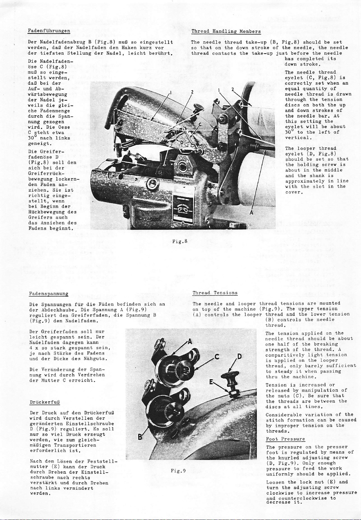
Fadenfiibruneen
Der
Nadelfadenabzug B (Fig.8)
verden,
der
Die
bse C (Fig.8)
muB
stellt
daB
nung
30°
Greiferriick-
daO
der
tiefsten
Nadelfaden-
so
einge
verden,
bei
der
Nadelfaden
Stellung
der
gezogen"
nach
links
muB
den
Haken
Nadel,
so
eingestellt
kurz
leicht
vor
beriihrt.
Thread
The
needle
so
that
thread
contacts
C
f
Vf/SMKM
Handling
thread
on
the
Members
take-up
down
the
stroke
take-up
(B,
of
just
Fig.8)
the
has
down
The
eyelet
r
/'.
ik
correctly
equal
needle
through
discs
^Qd
the
, this
r
should
needle,
before
completed
stroke.
needle
(C,
quantity
thread
the
on
down
needle
setting
be
set
the
needle
the
needle
its
thread
Fig.8)
set when
both
strokes
bar.
of
is
tension
the
At
the
is
an
drawn
up
of
das
Anziehec
Fadenspannung
Die
Spannungen
der
Abdeckhaube.
reguliert
(Pig.9)
Der
leicht
Nadelfaden
4 X so
je
and
Die
nung
der
Driickerf
Der
wird
geranderten
D (Fig.9)
nur
werden,
maBigen
erforderlich
Nach
mutter
durch
schraube
verstarkt
nach
werden.
den
Greiferfaden
gespannt
stark
nach
Starke
der
Dicke
Veranderung
wird
Mutter C erreicht.
uB
Druck
durch
so
viel
wie
Transportieren
dem
Lbsen
(B)
Drehen
nach
links
des
fiir
die
den
durch
auf
reguliert.
und
Die
Greiferfaden,
Nadelfaden.
soli
sein.
dagegen
Verstellen
Einstellschraube
Druck
zum
kann
vermindert
kann
gespannt
des
Fadens
des
Nahguts.
der
Verdrehen
den
DriickerfuB
erzeugt
gleich—
ist.
der
Peststell<
der
der
Einstell
rechts
durch
Span
Paden
soil
befinden
die
Spannung
Spannung A (Fig.9)
nur
Der
sein,
der
Es
Druck
Drehen
sich
B
an
Pig.9
Thread
The
on
(a)
^
lA
apF
r
Tensions
needle
top
of
the
controls
^
'
- "^WBrSHHiW
and
looper
machine
the
P
/
j
thread
(Pig.9).
looper
'■
tensions
The
thread
(B)
thread.
The
needle
one
strength
and
controls
tension
thread
half
comparitively
is
applied
thread,
steady
thru
the
Tension
released
the
nuts
the
threads
discs
at
Considerable
stitch
formation
improper
are
upper
the
lower
the
applied
should
of
the
of
the
light
on
the
only
barely
it
when
machine.
is
increased
by
manipulation
(C).
Be
are
all
times.
variation
tension
mounted
tension
needle
on
breaking
thread.
tension
looper
sufficient
passing
sure
between
can
threads.
Foot
Pressure
The
pressure
the
knurled
(D,
Pig.9).
pressure
uniformly
Loosen
turn
the
clockwise
and
counterclockwise
decrease
to
the
adjusting
it.
on
adjusting
Only
feed
should
lock
to
increase
the
by
enough
the
be
nut
screw
tension
the
be
about
A
or
of
that
the
of
be
caused
on
the
presser
means
screw
work
applied.
(E)
and
pressure
to
the
Page 12
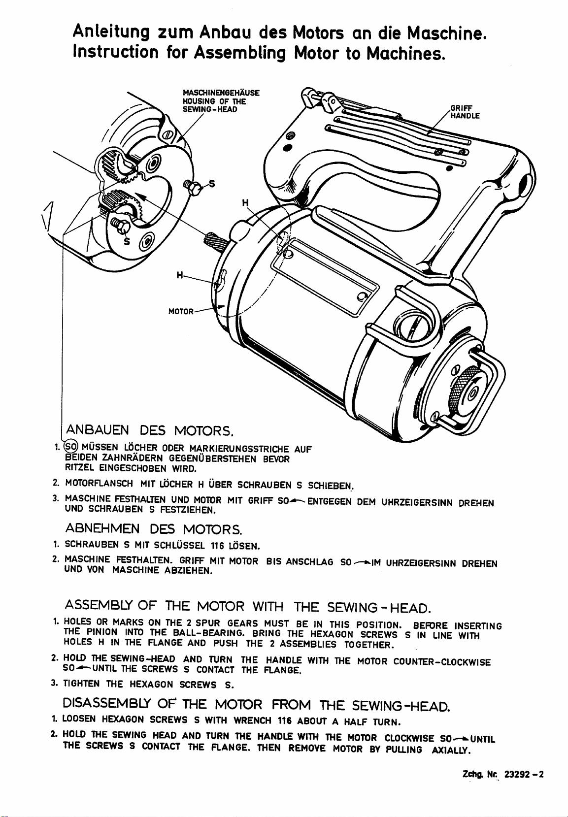
Anieitung
zum
Anbau
des
Motors
an
die
Maschlne.
Instruction
for
Assembling
MASCHINENGEHAUSE
HOUSING
SEWING-HEAD
MOTOR
OF
THE
Motor
to
Machines.
GRIFF
HANDLE
ANBAUEN
1.^
MUSSEN
BEIDEN
RITZEL
MOTORFLANSCH
MASCHINE
UND
SCHRAUBEN S FESTZIEHEN.
LOCHER
ZAHNRADERN
EINGESCHOBEN
FESTHALTEN
ABNEHMEN
SCHRAUBEN S MIT
MASCHINE
UNO
VON
FESTHALTEN.
MASCHINE
ASSEMBLY
THE
PINION
HOLES H IN
2.
HOLD
THE
SO-—-UNTIL
3.
TIGHTEN
INTO
THE
SEWING-HEAD
THE
THE
HEXAGON
DISASSEMBLY
1.
LOOSEN
2.
HOLD
THE
HEXAGON
THE
SEWING
SCREWS S CONTACT
DES
MIT
OF
SCREWS S CONTACT
MOTORS.
ODER
MARKIERUN6SSTRICHE
6EGENUBERSTEHEN
WfRD.
UDCHER H USER
UNO
MOTOR
DES
SCHLUSSEL
THE
FLANGE
SCREWS S WITH
HEAD
MOTORS.
116
GRIFF
ABZIEHEN.
THE
MIT
MOTOR
BALL-BEARING.
AND
PUSH
AND
TURN
OF
SCREWS
THE
AND
THE
S.
MOTOR
TURN
FLANGE.
MIT
LdSEN.
AUF
BEVOR
SCHRAUBEN S SCHIEBEN.
GRIFF
SO
MOTOR
BIS
WITH
BRING
THE 2 ASSEMBLIES
THE
HANDLE
THE
FLANGE.
FROM
WRENCH
THE
116
HANDLE
THEN
ENTGEGEN
ANSCHLAG
THE
THE
WITH
SO
SEWING-HEAD.
'N
THIS
HEXAGON
THE
THE
ABOUT A HALF
WITH
THE
REMOVE
MOTOR
DEM
UHRZEIGERSINN
^IM
UHRZEIGERSINN
POSITION.
SCREWS S IN
TOGETHER.
MOTOR
BEFORE
LINE
COUNTER-CLOCKWISE
SEWING-HEAD.
TURN.
MOTOR
CLOCKWISE SOUNTIL
BY
PULLING
AXIALLY.
DREHEN
DREHEN
INSERTING
WITH
Zchg.Nr.
23292-2
Page 13
ANSICHT
VIEW
IN
0
ACHTVN6!
OtSTELLEN
6EE16NETES
OLSTEaEN
CAUTION
OIL
TOOILSPOTS
RECOMMENDED
POINTS
IN
RICHTUNG.A
DIRECTION
1-11
1.2U.3
I
SHOULD
1.2
and 3 ARE
OL;
BE
1-11
..A
TAGUCH
APPUED
OIL:
1>iOLEN
MOBIL
D.T.E.O!L
BESONDERS
DIRECTLY
ONCE A DAY.
MOBIL
D.T.E.
ESPECIAUY
MEDIUM
WICHTIG
OIL
IMPORTANT
MEDIUM.
(Auf
(
ON
RiKkscite)
TKG'REAR
SIDE)
OL-UNO
EINPi^DELANLEITUNG
OIUNG
AND
THREADING
PUR
DIAGRAM
MASCHINEN
FOR
MACHINES
OER
CLASS
KL.
2100
Zchg.Nr.
2100
23221-1
Page 14

ZUSATZTEILE
UND
EINPXDELDIAGRAMM
PUR
BEILAUPGARN
ADDITIONAL
ASSEMBLY
kpl,
AND
THREADING
Teilesatz G 29499
ompl*
set
DIAGRAM
G
29499
PGR
PILTER
CORD
Pos.
REP.
10
Achtung!
Bohrungen
miissen
Caution!
Holes
to
be
Stuck
AM'T
1
2
3
4
3
6
7
8
9
1
2
1
1
1
2
1
2
1
1
Teil-Nr.:
PABT-NR.:
2189
22570
2189
2189
99270
22585
2189
41071
2158
2158
Benennung
G
Ftihrung
A
Schraube
CA
Fadenstange
B
Garnrollenhalter
Schraube
A
Schraube
EB
Platte
G
Sechskantmutter
G
PadenfUhrung
P
FadenfUhrung
im
gut
verrundet
in
preaser
rounded
DrilckerfuO
und
foot
for
and
thread
fUr
Beilaufgarn
fadenpoliert
filter
cord
polished
DESCRIPTION
THREAD
EIELET
SCREV
THREAD
SPOOL
SCREW
SCREV
CONE
NUT
THREAD
THREAD
VIRE
PIN
SUPPORT
ETELET
EIELET
are.
Page 15

1
i
m
1
Vpe
11
Stitch)
^33
101}
m
Page 16

Pos.
Hef.
Nr.
No.
Toil
Part
Nr.
No.
Bezeichnung
Deacriution
Anzahl
Amt.Req.
1
2
3
4
5
6
7
8
9
10
11
12
13
14
15
16
17
18
19
20
21
22
23
24
25
26
27
28
29
30
31
32
33
34
35
36
37
38
39
40
41
42
43
44
45
46
47
48
49
50
51
52
53
54
55
56
57
58
59
60
61
62
G
G
51292
51292
51292
109
2186
51292
668-27
21114
51192
99270
2189
2189
2189
2189
2159
93640
41071
43266
22528
22585
22585
41071
2158
41071
51758
2158
2158
39236
2163
29496
2196
2146
2146
2196
2176
2176
2193
2176
99268
2166
2179
2180
80175
2126
87
2169
2167
907
2168
41071
2120
87
2178
80175
2160
2143
2175
79
93
87
93
28
P-
P-
C
A
M
G
E
B
C
A
G
A
A
G
A
U
G
C
D
A
A
A
B
A
C
A
G
A
Fadenap.-Peder
Padensp.-Feder
f.
f.
Greifer
Nadel
Padensp.-Mutter
Padensp.-Scheibe
Padensp.-Bolzen
Padengl e i t hiil s e
Padenbse
Pederring
Padenleitvinkel
Schraube
Schraube
Platte
f«
2189
f.
Garnrollenstdnder
B
Spulenstift
Padenstange
Schraube
Garnrollenstdnder
Abdeckhaube
Stellschraube
Mutter
Mutter
Schraube
Schraube
Schraube
Mutter
Einfachkettenstichmaschinen)
Nade1faden-Abzug
Scbraube
Mutter
(nur
(Schr.79)
kompl.
bei
alteren
Nadelfadenfiihrung
(Stichtype
101)
GreiferfadenfUhrung
Nadelfadenfiihrung
Scheibe
Blattfeder
Abdeckhaube
Buchse
kompl.
f.
Schubstange
Schubstange
Schubstange
Buchse
Auflage
Schraube
hebel
kompl.
f.
Obertransporthebel
f.
Peder
f.
Obertransport
Obertransporthebel
Buchse
Obertransporthebel
Schraube
Schraube
f.
Obertransporthebel
kompl.
Stellring
Velle
f.
Obertransportweg
Obertransporteurhalter
Schraube
Obertransporteur
Schraube
Gelenkzapfen
Kurbel
Mutter
Gelenk
Mutter
OriickerfuB
Schraube
Antriebshebel
Schraube
Doppellager
Buchse
zugleich
DriickerfuBhebel
kompl.
f.
Obertransport
Nadelhebelachse
u.
Tension
Tension
Tension
Tension
Tension
Tension
Spring
Spring
Nut
Disc
Post
Post
Eyelet
Eyelet
Tension
Screv
Screw
Cone
Spool
Thread
Screw
Cone
Needle
Thumbscrew
Nut
Nut
Screw
Screw
Screw
Nut
101
Needle
Screw
Nut
Needle
(101
Looper
Needle
Washer
Presser
Needle
Bushing
Connection
Locking
Thread
for
Support
Pin
Wire
Support
Lever
(only
Stitch
Thread
Thread
Stitch)
Thread
Thread
Spring
Lever
for
Connection
Bushing
Presser
Screw
Upper
Bushing
Upper
Screw
Screw
Collar
Upper
Upper
Screw
Upper
Screw
Link
Crank
Nut
Link
Nut
Presser
Screw
Upper
Screw
Upper
Ball
Bushing
also
Presser
for
Spring
for
Peed
for
Peed
Feed
Peed
Peed
Pin
Foot
Peed
Peed
Joint
for
Needle
Foot
for
for
Perrule
Ring
Eyelet
2189
B
(Screw
complete
Cover
for
older
Machines)
Pull-off
Eyelet
Eyelet
Eyelet
Cover
Connection
Rod
Rod
complete
Upper
Rest
Upper
Peed
Lever
Upper
Lever
complete
Shaft
Dog
Holder
Dog
Rocker
Motion
complete
Upper
Lever
Lever
Looper
Needle
79)
Assembly
Rod
Peed
Lever
Lever
Peed
Lever
Double
Peed
Rocker,
Shaft
Page 17

0.
u—f-^
-Q
801
•1
k
SGI
/
Page 18

Pos.
Ref.
Nr.
No.
Toil
Part
Nr.
No.
Bezeichnung
Description
Anzahl
Ami♦Reg
46
47
48
49
50
51
52
53
54
55
56
57
58
59
60
61
62
63
64
65
66
67
68
69
70
1
2
3
4
5
6
7
8
9
10
11
12
13
14
15
16
17
18
19
20
21
22
23
24
25
26
27
28
29
30
31
32
33
34
35
36
37
38
39
40
41
42
43
44
45
G
G
G
G
G
G
29492
96502
73
2152
2142
2151
660-210
660-210
2152
96603
96602
99277
2105
80175
2125
2108
2108
2144
2193
88
22764
99521
2173
2174
87
2134
93
2153
HA
61
2134
29495
2135
39236
660-210
2136
2139
39250
2156
2131
2132
2133
12934
2140
2115
96501
99267
22575
2158
41071
2177
2158
77
88
28
28
2145
87
77
2165
2194
2165
2165
22764
22560
2165
2195
2182
2182
28
28
Greiferantrieb
C
C
Zyl.-Stift
Schraube
Schraube
Kugelgelenk
Hebel
f.
Gelenk
f.
Benzing-Sicherung
B
Benzing-Sicherung
GelenkstUck
Zyl.-Stift
Zyl.-Stift
Schraube
Transporteur,
Schraube
Nadelanschlag
Greifer
stich
A
Greifer
stich
Greiferwelle
B
A
Buchse
Schraube
Schraube
Federscheibe
Obermesserantrieb
f.
(Stichtype
f.
(stichtype
im
Kugel
U
Schraube
Transporteurhalter
Schraube
D
A
Greiferwellenmitnehmer
Schraube
Transporteurhalter
Obermesserantriebshebel
kompl.
A
Briickenhebel
Unterlegscheibe
Benz
ing-S i c
Transportge1enkbo1z
Doppelkugellager
J
Mutter
Greiferfiihrungsbahn
Transportachse
Stellschraube
A
Einlegscheibe
Mutter
Buchse
Nadelhebel
f.
Zylinderstift
Schraube
E
G
B
L
B
C
A
A
K
B
C
A
A
B
D
D
A
Schraube
Fadenfiihrung
Mutter
Bolzen
f.
Fadenfiihrung
Schraube
Schraube
Schraube
Schraube
Lagerfuhrung
Schraube
Schraube
Ausgleichsgewicht
Buchse
im
Unterlegscheibe
Zahnrad
Spitzschraube
Schraube
Unterlegscheibe
Buchse
im
Dichtungsscheibe
Abdeckgummi
Schraube
kcmpl.
kcmpl.
Greiferantrieb
Greiferantrieb
unten
Doupelketten-
401
Einfachketten-
101)
Gehause
auf
Achse
kompl.
he
rung
Greiferwelle
am
Schubstange
am
f.
Gehause
Gehause
en
kompl.
Nadelhebel
Nadelhebel
Doppellager
auf
aus
)
Zahnrad
Gummi
Looper
Pin
Screw
Screw
Ball
Looper
Connection
Motion
Joint
Motion
complete
Snap-Vasher
Snap-Vasher
Connection
Pin
Pin
Screw
Lower
Feed
Screw
Needle
Looper
Stitch
Looper
Dog
Guard
for
Double-Locked
(Stitch
for
Single-Thread-
Locked-Stitch(Stitch
Looper
Bushing
Screw
Screw
Spring
Upper
Ball
Screw
Lower
Screw
Looper
Screw
Lower
Upper
Assembly
Feed
Vasher
Snap-Vasher
Bolt
Feed
Joint
Nut
Looper
Feed
Stitch
Stitch
Nut
Bushing
Needle
Pin
Screw
Screw
Needle
Needle
Nut
Bolt
Needle
Needle
Screw
Screw
Screw
Screw
Needle
Ball
Screw
Screw
Balance
Bushing
Spacer
Gear
Spot
Screw
Spacer
Bushing
Rubber
Ball
Rubber
Screw
Shaft
in
Vasher
Knife
Feed
Shaft
Feed
Knife
Motion
Motion
complete
Avoid
Rocker
Regulating
Regulating
for
Lever
Thread
Lever
for
Connection
Thread
Lever
Lever
Joint
for
in
between
Screw
between
in
Vasher
Joint
Plate
Housing
Lever
Bar
Cross
Bar
Lever
Lever
Double
Cross
Shaft
Looper
Motion
Guide
Gear
Housing
Housing
Lever
Lever
Type
of
Shaft
complete
Eyelet
Eyelet
Gear
Gear
below
Assembly
401)
Type
Rocker
Head
Rocker
Rocker
Ball
Head
Screw
Stop
Shaft
on
Rod
on
Double
Double
101)
Guide
1
4
von
71
-
140
siehe
folgende
Seite
from
71 - 140
see
following
Page
Page 19

137
Page 20

Pos.
Ref.
von
Nr.
No.
1
-
70
Teil
Part
siehe
Nr.
No.
vorhergehende
Bezeichnune
Seite
Description
from
1-70
see
preceding
Anzahl
Ami.Reg.
Page
100
101
102
103
104
105
106
107
108
109
110
111
112
113
114
115
116
117
118
119
120
121
122
123
124
125
126
127
128
129
130
131
132
133
134
135
136
137
138
139
140
71
72
73
74
75
76
77
78
79
80
81
82
83
84
85
86
87
88
89
90
91
92
93
94
95
96
97
98
99
/
G
G
G
G
22764
80265
22804
22764
22560
2130
2124
2127
76099
2127
2127
2182
29497
2170
2171
22764
22542
2150
2149
2183
J
1614
99269
G
2172
99266
99266
99266
99266
2141
22825
2157
2122
2145
96500
22528
22585
2182
2182
96500
22571
2129
22528
39236
29490
2155
2154
10349
2101
87
2101
88
2162
2161
2165
2195
2165
87
2165
2165
2164
2111
28
77
87
87
90
73
88
538
303
318
B
A
A
C
A
B
A
B
K
A
U
A
B
C
B
B
C
B
A
A
Abdeckblech
Schraube
Abdeckblech
kompl.
Spitzschraube
Schraube
HaltestUck
Unterlegscheibe
Schraube
Kugelwalzlager
Ritzel
dltere
Type
auf
Maschinen
UM
63-5
der
S
Motorwelle
Spitzschraube
Buchse
im
Gehause
Unterlegscheibe
Schraube
Ausgleichsgewicht
Zahnrad
Buchse
Schraube
Schleifenhalter
Schraube
Schraube
im
Gehduse
Stichplattenauflage
Schraube
Stichplatte
Schraube
KettelfuB
Anschlagstift
Druckfeder
Ke t te 1 f
Schraube
Abdeckblech
Stichplatte
uBf
lihrung
mit
KettelfuB
kompl.
Obermesser
Schraube
Messerhebel
Schraube
f.
Obermesser
Spitzschraube
Schraube
Schraube
Halter
Untermesser
Abdeckblech
Federscheibe
Schraube
Sec
Velle
Schraube
Schraube
Schraube
Schraube
Nadelhebelwelle
Schraube
VerschluBklappe
f.
hskantsc
f.
Untermesser
hraube
Messerhebel
kompl.
Doppelkurbelwelle
Doppellagerschale
Zylinderstift
Schraube
Schraube
Schraube
Deckblech
Abdeckgummi
am
Gehause
Zylinderstift
Schraube
Gehause
Schraube
Scheibe
kompl.
Doppelkurbelwelle
Doppellagerschale
Kugelschraube
Kugelschraube
mit
Motor-
auf
kompl.
fiir
Zahnrad
Cloth
Plate
Screw
Cloth
Plate
Spot
Screw
Screw
Clamp
Plate
Spacer
between
Screw
Ball
Bearing
Driving
Machines
DM
63-5
Spot
Screw
Bushing
Spacer
Screw
Balance
Gear
between
for
Bushing
Screw
Loop
Retainer
Screw
Screw
Auxiliary
Screw
Throat
Screw
Plate
Chaining
Locking
Pin
Chaining
Chaining
Screw
Stitch
Throat
Block
Upper
Screw
Upper
Screw
Spot
Screw
Screw
Lower
Lower
Looper
Spring
Screw
Screw,
Upper
Screw
Screw
Screw
Screw
Needle
Screw
Front
Crank
Regulating
Plate
Assembly
Knife
Knife
Screw
Knife
Knife
Chamber
Vasher
hexagonal
Knife
Lever
Cover,
Shaft
Bearing
Pin
Screw
Screw
Screw
Plate
Rubber
Needle
Pin
Screw
Housing
Screw
Vasher
Plate,
Lever
complete
Crankshaft
Bearing
Ball
Stud
Hexagonal
Gear
with
S
in
Housing
in
Housing
Throat
Block
Block
Block
for
Holder
Lever
Assembly
Socket
complete
Gear
for
older
Motor-Type
Gear
Gear
Plate
Spring
Guide
Chamber
and
Chaining
Assembly
Cover
Head
Shaft
Shaft
complete
right
Ball
i
2
1
l
1
2
2
2
of
Screw
Page 21

Handgriff
Handle
mit
with
Motor
Motor
(50
(50
V-240
V-240
V)
V)
220
V
50
Hz
220
V
50
Hz
220-2«OV
60
220-2i0V
60
2^0
V
50
Hz
2(0
V
50
Hz
110-125
60
110-125
60
110-125V
50
110-125
50
50
V
50
Hz
50
V
50
Hz
Motor
(V
und
Hz)
Pos.
1
DET
1
ACHTUN6I
ATTENTION
629
629501AA
629501C
Hz
629501
Hz
629501K
629501KA
V
629
Hz
V
629501BA
Hz
6295010
Hz
V
629
Hz
629501E
629501EA
Hondgriff
m.Moior
HANDLE
withMOTOR
Teil - Nr.;
PART-NO.:
501A
501B
501
997A-S00
OA
DA
Motor
Teil-
Bei
I
Please
997A-5C0
9970-500
9970-500
997K-500
997K-500
9978-500
9978-500
9970-
500
9970-500
997E-500
997E-500
ohne
Handgriff
Motor
without
HANDLE
Nr.:
PART-Na:
ErsatztellbssteUung
indicate
6212330
621233 DA998-
621233
D
621233
OA
621233
0
621233
DA
621233
0
621233DA
6212330
621233 DA998-53
621233
D
621233
DA
6ummi
-
DET.
Kondenso-
CONDEN-
2
2
-kobel
CABLE
Pos
Motortyp,
the
motortype.
-tor
-SER
998-58
53
998-58
53
998-
53
998-58
998-58
53
998-
53
998 - 58
53
998-
998-58
998-57
998 - 57
Orossel
0H0KIN6
-COIL
Pos.
3
DET.
3
998-
998-
998-53
998-
998-
998-
998- 53998-
998-53
998-5(
998-5(
Pos.
DET.
Spannung
voltoge
621233
621233
58
621233
58
621233
58
621233
58
Stecker
(
(
ond
99S-U(
PLU6
Pos.
DET.
5
5
und
Frequenz
frequency
when
22
E
71
20
19
E
18
17
16
E
15
U
E
12
11
in
E
9
8
7
6
5
(
3
2
1 1
Pos.
DET.
ongeben.
ordering
1
6
1
6
1
1
1
621233K
1
6
998-
2
1
998-172
2
1
1
1
6212330M
1
X
1
X
1
1
X ' *)
X
1
X
Stiick
Teil - Nr.:
PART-NO:
AM'T
spore-ports.
LOstcrklemme,
21233H
80265
Schelbe
2276(A
Spitzschroube
Schroube
22
585
JsoUerplotte
SCholterfeder
212331
59
Lusterklemme,2
Kobelschelle
Erdungsdchniube
99
313
2121
Hondrod
Scholter
216(M
Hondoriff
X)
Stecker
xl
Orossel
Kondensotor
x)
Dummikobel
Motor
x)
Pos.5
Pos.l
0ET.5
Benennung
siehe
SEE
Ipolig
poUg
kompl.
linke
LEFT
TERMINAL
WASHER
SPOT-SCREW
SCREW
JNSULATIN6
SWITCH - SPRING
TERMINAL
CABLE - HOLDER
SCREW
PULLEY
SWITCH
HANDLE
PLUG
CHOKING
CONDENSER
CABLE
ELECTRIC-MOTOR
DESCRIPTION
Tobelle
TABLE
-PLATE
FOR
-COIL
COMPLET
MOTOR
entfollt
bei
Lleferung
noch
USA
delivering
to
A B
-h
LIVE
Conductor
schworz
BLACK
rot
RED
Kobel
G21
2330 - Kobe*.
621233DE
USA
return
insteod
NEUTRAL
Conductor
weiS
WHITE
schworz
BLACK
621233
of
DE
Coble 6 21233
eorthed
D
C
Erde
GROUND
Conductor
rot
RED
gr&n
GREEN
Lieferung
DELIVERING
Deutschlond
USA
Englond
''iBei
Lieferung
"IWhen
noch;
to:
noch
delivering
net
necessory
Teil-Nr.-Kobel
fVlRT-Na-CABLE
621 233
D
621
233
621
233
Englond
England
onstelle
use
to
when
outgoinq
DA
OE
Coble
Funkfntltir-Oappt^
■Orotitl
(PCS. ( I
RADIO-SCREENED-!
0U8LE-CK0KING
•COlUDETtI
Brttibond-Enlitar-
KondintotociPOS
WIDE - BAND
CIEAR-CONOE
-
(DET.
Schaltplan
WIRING-DIAGRAM
Zchng
Nr
23218-2
Page 22

Handgrjff
Handle
mit
with
Motor
Motor
(42V)
(42V)
25
2
k
23
22
2
1
20
1
9
1
B
1
7
1
B
1
5
1
k
1
3
1
2
1
1
1
U
9
8
7
6
5
k
3
2
1
Pos.
Stikk
DET.
AM'T
""")Pos.9
DET.g
UObh
nSfflH
80mn
i
1
1
1
1
1
1
1
1
1
1
1
2
1
1
1
1
1
siehe
SEE
998 - 201
998
-200
998 - 200
998-U4@
G21233H
998-55
998-56
80
265
G2276AA
99313
22585
G21233K
621233
998-59
998-172
95151
"")
2121
621233CM
216£M
997F-500
Teil-Nr.
PART-NO.:
untere
TABLE
ersotzt«llwst#llung
JsoUersdilaueh
SchaltdiQht
Schaltdiaht
stecker
"■)
LOsterfclmme.l
Kleinkondensotcr
KleinkoRdensator
Scheibe
Spitzschraube
Bdunqsschmube
Schroube
Jsolierplatte
1
Sehclterfeder
biisterklemme,
Kobelscheite
Schroube
Gumnnllcabel
Hondrad
Schalter
Kondgriff
Motor.
:
42V-S0
Benennung
poUg
2poUa
kompl.
Hz.
Motortyp,
TERMINAL
SCREW
CABLE
PULLEY
SWITCH
ifANDLE
ELECTRIC-MOTOR
Tabelle
BELOW
S0onnuRg
JNSULAT1N6-TUBE°.^W
WlREJ)30-x6i>;'5t''lona
WlRE^30-x3
PLUG
"»)
TERMINAL
CONDENSER
CONDENSER
WASHER
SPOT-SCREW
SCREW
SCREW
JNSULATING - PLATE
SWITCH - SPRING
CABLE-HOLDER
COMPLET
DESCRIPTION
undFreguenz
Vii^lono
FOR
MOTOR
ongcben.
A
KltinkondtnurtoilPOS
CONDENSER(OET
KltiRkaiMl*niotor(ras
CONOENSERIOEt
20)
20)
t9)
19)
Schaltplan
WIRING - DIAGRAM
_
entfalU
bci
Lieferung
DEUVERIN6
Deutschland
USA
Englond
Pos.9 / DET.
nach:
to:
notnecessory
Tetl-Nr-Kabel
FART-NO.-CABLE
G
G
621
9
21
233
D
21
233
DA
233
DE
outooinq
schworz
BLACK
rot
RED
Lieferung
LIVE
when
A
-f-
Conductor
noch
USA
delivering
return
■■)
to
USA"")
B
NEUTRAL
Conductor
weifl
WHITE
schworz
BLACK
GROUND
earthed
rot
RED
griin
GREEN
C
Erde
Conductor
*)Bei
Kobel
G212330
*)When
Cable
Lieferung
-Kobel
delivering
G21233OE
Zchng.Nr.
nochEnglond
G21
233
to
England
of
use
Cable
instead
23218-2
onstelte
DE
G21233
D
Page 23

Handgrlff
Handle
mit
with
Motor
Motor
fur
Maschinen
for
Machines
mit
Tasterschaltung
with
Feeler
Controlled
(
50
V-
240
V)
Switch. ( 50
V-240
V)
220
V
50
Hz
220
V
50
Hz
220-240V
80Hz
220-240V
60
240
V
50
Hz
240
V
50
Hz
110-125
60
Hz
flO-125V
60
!10-125V
50
110-125
SO
50
V
50
Hz
50
V
50
Hz
Motor
(V
und
Hz)
Pos.
1
DET.
1
GT29501A
6729501AA
6T29501C
6T29501CA
Hz
Gr29501K
GT2S501KA
V
GT29501B
6T29501BA
Hz
GT29S01D
Hz
V
0729501
Hz
GT29
501E
Gr39501EA
Hondgnff
m
Motor
HANDLE
withMOTOR
Toil-Nr.
PART-
NO:
jentfclU
jnotnecMsory
5
ACHTUN6I
ATTENTION
g97A-500
997A-500
997C-500
997
C-500
997
K-500
997K-500
997B-500
997
B-500
997
D-
997
D-500
OA
997
E-500
997E-500
Motor
ohne
Hondgnff
Motor
without
HANDLE
:
Teil - Nr.;
PART-NO.:
b«i
Liefcrung
B«i
PteoM
I
G21233D
G212330A
621233D
G212330A
621233
621233
621233
G21233DA
500
621233D
621233DA
6212330
621233
Gummi
-kobel
CABLE
Pos.
DET
nach
when
delivering
ErsatztwlbtsttUung
indicote
998-53
998-
998-
998-53
998-
0
DA
998-
998-53
D
998-
998-
998- 53998-
998-
998 - 54
OA
Kondcnso-
-
-tor
CONDEN-
-SER
2
Pos.
DET.
2
21
14
Ihe
motorlyp#.
998-58
993-58
53
998-58
53
998-58
998-58
53
998-58
53
998 - 58
998-58
53
998-58
53
998-57
54
998
Drossel
CHOKING
•COIL
Pos.
3
DET.
3
Metortyp.
58
-57
4
4
22
^
23
USA
to
USA
t
^
Spannung
vollag#
621233
621233
621233
021233
621233
998-144
Stacker
PLUG
Pos.
DET
4
\ \
18
^
5
5
and
E
E
E
E
E
und
Frtquanz
frequmey
23 i 1
22 1 1
21
"20 ] 1
19 1 2
18
17 ! 1
16 [ 1
is • 1
'14
13
12 ■ 1
11
10 ^ 1
9 ■
8 ■
7^
6 1
s ' 1
4 1
3 1
2 ; 1
1 i
Stiick
Pos.
DET.
AM'T
7
16
\
I
17
11
ongtbtn.
whan
ordering
99313
6
21233K
80265
1
6
22764A
22
562A
1
»585
621
i233K
6
212331
998-
59
998-172
1
95151
2
6294997
639
2S0Ai
1
212iBT[La9erschrid
2121
1
214771
1
621233CMischaltsr
1
2164M'Hondgriff
X
X)
X
x)
xl
Teil - Nr.:
PART-NO:
_
,Kondensotor
X
X)
1
.XX)
_ X «)
' X
spore-ports
Erdunqsschroube
Lusterkletiune.
Scheibe
Spitzschroube
Schraube
Schreuiie
Jsollerplottc
Scholt^eder
U)sterklemme,2
KobtL^eUe
^hroubs
Mikroseholter
Kobel-Durehfuhiung
Kondrod
Fddsr
Stacker
Drossel
Gummtkobel
Motor
Pos.1
DET1
Ipolig
polig
kpl.
furScholter
Benennung
-Pos.5
siehe
-0ET.5
SEE
Durch
die
Feder
der
Kontakt
G
21233
CM
gesehlossen.
SPRING
2U7T
KEEPS
CONTACT
MICRO-SWITCH G 21233
PERMANENTLY
SCREW
TERMINAL
jWASK^
■SPOT-SCREW
SCREW
SCREW
'jNSULATING-PLATE
SWITCH • SPRING
TERMINAL
CABLE-
HOLDER
;SCREW
i
SWITCH
!
RUBER
JNSUL.
'bearing
IPULLEY
'spring
■SWITCH
HANDLE
PLUG
'choking
.CONDENSER
CABLE
ELECTRIC-MOTOR
DESCRIPTION
Unhe
Tobelle
LEFT
TABLE
2U7T
3-i
am
(Pos.7)
(REE
3-4
ENGAGED.
aANGE
.
FORMOTok
-coil
(Pos.8)ist
Mikroseholter
dauemd
NO.
B)
OF
THE
CM
(REE
»«odi
»cfMcr»
RIN6'
_
Na71
Llefervng
DELIVERING
Deutschlond
USA
England
"iwhen
noch:
Teil-Nr.-Kobel
ta
RURT-NO-CABLE
delivering
toEnglond
621
621
621
233
233
233
D
DA
DE
use
outgoing
Coble
A
-h
LIVE
Conductor
schworz
BLACK
rot
RED
G212330E rotaod
return
B
NEUTRAL
Conductor
weiB
WHITE
schworz
BLACK
of
rnM>
■eorthed
1 rot
1 RED
j griin
n->1
r>
C
Erde
GROUND
Conductor
GREEN
FtinkeMstAe'Ooppeii
•OrMtel
{POS- i )
RAOIO-SCREENEO-
OOUBIE-CHOKINOm
•C0tL<DET4)'
Brtitbend-Ent«tdr-<
•Kofidfntater<POS3f
WIDE
•BAND-,
aeAA*CONOE»Q£R
-(0Et3>
Schaltplan
WIRING-DIAGRAM
ZchRg.Nr
23217-2
Page 24

Handgriff
Handle
mit
with
Motor
Motor
fiir
Maschinen
for
Machines
mit
Taster^chaltung
with
Feeler
Controlled
(42V)
Switch.
(42V)
22
I.
1
111.«.
19^
17 ! 1
16 ■ 1
15 ; 1
u i
15 ^ 2
12 T 1
11-
10 : i
"a"
. 5 I'}
Pos.
OCT.
6
1
62276£A
2
.
6
6
;
MS-
1
998-172 : Kobeischette
X.
• I
I
_G29<99TI
039290A.
i
9 ' i
I 2121
1
7_2
1
;621233CM;Scholter
6 .
1
t 1
3 ■ 1
2 ^ 1
1 :
.1
Stuck
teil-Nr:
AM'T
PART-NO;
A-JiUiIllJIJnJ.i
ATTENTION I Ptoas*
21233K
Uisterktemme.lpoUg
80265
Scheibe
Spitzschroube
22S62A
Sdtroube
22585
jSchfoube
21233KI
Jsolierptotto
2123311
SchoUcrfedcr
59
:ijQstei1<Un«ne,2poUg
95151 ; Sehroube
Mikrosehalter
kobel-OurchfOhning
2121 OTj
Logerschfld
Kondrod
2U7T
Feder
f.
Scholter
216tM;
Handgriff
X)
,
Stacker
_
Kondensotor
X)
x)
.
Kondensotor
,
Gumntikobel
")
x1
i
Motor
Benennung
X
X)
Pos.1
-Pos.5
DCT1
-0CT.5
indieot*
TERMINAL
WASH^
SPOT-SCREW
SCREW
SCREW
Ijnsulatino-platC
I
SWITCH-SPRING
;
terminal
CABLE-HOLDER
SCREW
kpL
SWITCH
[RUBER
'bearing
'pulley
!
SPRING
i
SWITCH
HANDLE
PLUG
'condenser
,CONDENSER
CABLE
ELECTRIC-MOTOR
sieherechte
SEE
RIGHT
the
motortyp*.
JNSUL.
flange
FOR
DESCRIPTION
Tabelle
TABLE
Motortyp.
Spannung
voltog#
23
24
25
26
Pos
DET.
RING
MOTOR
42
SO
42
SO
Motor
(VundHz)
Pos
DET.
und
Frtquenz
and
frequency
1
99
I40»
I75wi
SOini
Stuck
AM'T
V
Hz
V
Hz
1
1
313
998-
998-200
998-200
Teil-Nr
PART-NO.
0129S01F
GT39501FA
Handgriff
m
Motor
HANDLE
withMOTOR
Teit - Nr.;
PART-
ND:
201
ongebin.
when
ordering
spore
Erdungssdiraube
Jsolieischlaudi
Stohldroht
Stohldraht
■
Benennung
Motor
without
ohne
6212330
6212330a
Gummi
-kobel
CABLE
9g7F-500
997F-500
Motor
Handgriff
HANDLE
TSil - Nr-
PART-NQ:
-ports.
•
Pos.
2
DET
2
SCREW
JNSUUDNG-TOBE
WIRE
WIRE
DESCRIPTION
998-55
998-
55
Kondenso-
-tor
CONDEN-
-SER
Pos.
3
DET.
3
998-56
998 - 56
Kondenso-
-tor
CONDEN-
-SER
Pos.
4
DET.
4
998-144
Stecker
PLUG
Pos.
DET.
5
5
Lieferung
DELIVERING
Oeutschlond
USA
Englond
IWhen
dellvving
ntfdut
not
noch;
Teil-Nr.-Kabel
ta
RftRT-NO-CABLE
621
G21
621
toEngland
bei
Lieferung
necestory
when
233
D
233
DA
233
DE
onsteUeKobel
use
Coble
noch
USA
delivering
to
USA
T
UVE
outooinaCOnductor
ichworz
BLACK
rot
RED
621
233D-Kobel
621233DE
nsteod
NEUTRAL
return
Conductor
welS
WHITE
schworz
BLACK
621
233DE
of
Coble G 21233
Erde
GROUND
eorthed
rot
RED
grOn
GREEN
D
Conductor
Durch
dee
Feder
der
Kontokt
G
21233
CM I Pos.
geschlossen.
SPRING
2147 T (
KEEPS
CONTACT
MICRO-SWITCH G 21233
PERMANENTLY
MO
JSS.
KlainkondtntatorPOS.
CONOENSERiOET.a
K(
ankonilMiiator
CONCENSERiOET.
)
(POS.
4)'
Schaltplan
WIRING-DIAGRAM
Zchng.Nr.
2U7 T I
3-L
REF.
ENGAGED.
4
23217-2
Pos.
am
Mikros^olter
7)
douemd
N0.8)
3-4
OF
THE
CM
01
(REE
ist
N0.7)
Page 25

8
M
(T
I
[J—Ll-I
1 i
J91_J
0
j
s
L_
0
23222-2
Page 26

Po8.
Ref.
Nr,
No.
Teil
Part
Nr.
No,
B e z e i e h n u
n_g
Description
Anzahl
Amt.Req,
1
2
3
4
5
6
7
8
9
10
11
12
13
14
15
16
17
18
19
20
21
22
12984
G
21233
22562
99279
G
21233
G
21233
G
21233
99013
G
21233
G
21233
G
39290
G
29497
2184
2120
2197
2197
2185
2147
2157
2124
T
T
73
A
BT
T
91
P-80/90
A
V
X
S
R
Z
A
T
T
T
T
Abdeckblech
T
DrUckerfuB
Taster
Schraube
Stellring
Stift
FUhrung
Schraube
Mikroschalter
Schraube
Schraube
Halter
Abdeckblech
f.
Mikroschalter
Gegenmutter
Rimdmutter
Kabel-TerschluBschraube
Kabel
Kabe1-Durc
Schalter-Blockierfeder
VerschluBklappe
Stichplatte,
Stichplatte
hfUhrung
kompl.
allein
kompl,
mit
Cover
Plate
Presser
Actuating
Screv
Collar
Pin
Guide
Screv
Switch
Screv
Screv
Switch
Cover
Plate
Nut
Nut
Plug
Screv
Cable
Rubber
Insul.
Spring
Front
Cover
Throat
Throat
Plate
Plate
Foot
Shoe
Support
Ring
cpl.
cpl.
KettelfUhrung
23
24
25
26
G
138
21233
22849
2197
Schraube
T
AT
Isolierplatte
Schraube
BUchse
f.
Taster
Screv
Insulating
S'^rev
Bushing
Plate
Page 27

8
13
U
-19
20
Uf
i
Page 28

Pos.
Ref.
Nr.
No,
Toil
Part
Nr.
No.
Bezeichnung
Description
Anzahl
Amt.Req,
12
13
15
16
17
18
19
20
21
22
1
2
3
4
5
6
7
8
9
10
11
14
0
G
G
G
G
G
G
G
6
G
G
G
G
G
6
G
G
G
20191
20191
20191
20191
20191
20191
20191
20191
20191
20191'
20191
20191
20191
20191
20191
20191
20191
20191
2188
99271
2199
99510
M-4
M-5
M-2
M-16
M-10
M-17
MA
M-14
H-3
M-9
M.13
M-18
M-12
M-15
M.6
M.8
M-7
M-11
A
Balancer-GehAuse
Soiltrommel
Zusammengesetztes
Zylindersehraube
Blattfeder
Senkschraube
Spiralfeder
Speuuibolzen
Druekfeder
Druckbolzen
Deckel
Linsenachraube
mit
Biegefeder
Sprengring
Baste
Haltefeder
Kerbstift
Beilegering
HaltebUgel
Schraube
Tragegurt
Karabiner
kompl.
Haken
Drahtseil
KugeldruckSler
Balance
Cable
Cable,
Housing
Drum
compl.
Cylindrical
Leaf
Spring
Countersunk
Coil
Spring
Stud
with
Ball
Pressure
Gun
Compression
Thrust
Cover
Slotted
Spring
Snap
Pawl
Retaining
Notched
Vasher
Supporting
Screw
Strhp,
Carabine
Pin
Screw
with
Ring
Spring
Pin
complete
Hook
Assembly
Screw
Screw
Oiler
Spring
Bending
Arm
for
Tag
Page 29

i
K
CO
A1
aOQD^^lOOOPOgOOOPOOOCJOOCOOOOOOOOOOOOOOOOOOOlTfc
00-
Page 30

Po8.
Hef.
Nr.
No.
Toil
Part
Nr.
No.
Bezeichnuni^
Description
Anzahl
Amt.Req.
1
2
3
4
5
6
Z-1-124
0
21208
95601
21225-4+0,45
9854-Div.
21202
125 g Baumwollgarn
Verkzeugtasche
SechskantstiftschlUssel
4
mm
SV
Qxeiferabstandlehre
Nadel-Type
Schraubenzieher
fUr
K1.2100
5,5
mm
125
gramm
Tool-Bag
Socket
4
Looper
mm
Vrench
across
Gauge
Needle-^pe
Screv
Driver
Cotton
flats
for
l/S"
Thread
Styles
wide
2100
Klingenbreite
21201
Schraubenzieher
3
mm
Screw
Driver
7/32"
wide
Klingenbreite
8
9
10
11
12
J
0
G
118
118
116
28604
43294
B
B
L
B
Einfhdler
Pinzette,
Mutterschliissel,
gebogen
S¥
Slkanne
Sler
7,2
mm
Threading
Thread
Vrench
Container
Oil
Tweezers
Can
Vire
of
Oil
for
Looper
Page 31

99266
2190
2193
2197
Nur
Tasterschaltung
ONLY
FOR
WITH
FEaER
CONTROLLED
A
AT
in
Maschinen
mit
MACHINEN
SWITCH
76000
n
96500
XX22571A
X
\99266
A1046
96500
Aiiiliji
,
410A6 G (KuoeloLer)
(SPRING
VALVE
G
OILER)
99266
18528-M
Page 32

Bandelnfass-u.
Tape-F=blder
Abschneldapparat
and
Cutting
Device
fur
for
Class
Klasse
2100
2100
(cpl.)
(kpl.)
19
20
21
24
22
17
23
26
27
Pos.
Sad
Teil
Nr.
DET.
AKI
PART-Na
1
2
22542
2
1
93077B
3
2
93077D
4
1
22837
5
1
93077
6
1
41031
7
1
93077
8
3
22596
9
1
2103AA-S
10
1
W8
<
2103AB
11
1
2103
1
1
1
2
2
1
629497A
1
AC
22269
J1614
39250
22585
22585A
2188
12
13
U
15
16
17
18
Benennung
Schraube
Bandfuhrunq
Bandrollenscheibe
RSndelschraube
A
RoUenhalter
E
Stellrinq
C
F«der
Schraube
Apparat
App.
Halter
Unterieqplatte
Ansatzschraube
Federscheibe
J
Mutter
A
Schraube
Schraube
Stichplatte
C
Halter
fQrAutostat
DESGRIPTION
SCREW
TAPE
GUIDE
TAPE
HOIUER
THUMB
TAPE
REEL
COLLAR
SPRING
SCREW
ATTACHMENT
BRACKET
SHIM
SHOULDER
SPRING
NUT
SCREW
SCREW
THROAT
hanger
for TCP
SCREW
HOLDER
FOR
SCREW
WASHER
PLATE
DISC
ATTACHMENT
CPL
unx
balancer
Pds.
DET.
19
20
21
22
23
24
25
26
27
28
29
30
31
32
Stock
1
1
3
1
1
1
4
1
1
1
1
1
1
2
Tell
Nr.
PART-NO.
99555
99556
22585R
80275
99560
22848
94
99559
2170
22724
96701
99557
99559
22570
Benennung
Messer
Messerwellen
Schraube
Untermesser
Rngerschutz
Schraube
Schraube
Fisder
A
Obermesser
Schraube
Zuqfeder
Messerwelle
Feder
A
Schraube
BetSbQurrcshebel
lager
KNIFE
BRACKET
SCREW
LOWER
RNGER
SCREW
SCREW
SPRING
UPPER
SCREW
SPRING
KNIFE
SPRING
SCREW
DESGRIPTION
ACTUA
TING
FOR
KNIFE
KNIFE
GUARD
KNIFE
SHAFT
LEVER
SHAFT
Page 33

[nr
SECTION A ENLARGED
Ausschnitt A vefor6»s«rt
r
p
u
IV
A
a
<o
<
j
OD
Part
Amt
Pes
Stch
Toil
U60P
1
1
95
1
?
3
1
U60S
4
12
@
G50-«80
U60V
1
5
6
1
95800
1025
7
1
1
U60W
8
U60
1
9
U60X
10
S
A
8998
11
1
1
*21
12
99271
1
13
A89g9E
1
IS1A8999A
1
A89S9
16
A899SD
17
1
181A89S9B
1013
1
19
22620
20
1
U01
21
1
1*03
1
77
1*60
1
23
2
9056S
7'-
C-53
SPT
R
D
B
T
No.
Nr
U
C
SECTION
Schnitt
DESCRIPTION
SuDDort
Sat
Scrow
Shaft
Pin
Soacer
Stud
Waahar
Clamo
nut
Clamo
Rubber
insulator
Traadla
eomol.
Chain
Scraw
Chain
Hooek
Switch
Lev.Brackr
Sorino
Pin
Switch
Lever
Soot
Screw
Sat
Screw
Base
Column
Clamo
Scraw.
Wood
Screw
B-B
B-B
BENENNUNG
Maschinan-Tracer
Schraubenstlft
Achse
Stift
Distanzrohr
Stiftschraube
UntarlaoBcheiba
Griffmuttar
Pratze
Unterlaoe
Fusstritt
Ketta
Schrauba
Haken
Halter
Fader
Stiff
Schalthobek'
Soitzachrauba
Stellsehraube
Saulanfuss
saule
1350mm
(SlSLanal
Griffschrauba
Holzschrauba
Kompl.
^
Comol.
[A8999
Lano
UNION
PEOeSTAI.
165UO
SPECIAI.
HI
too
Q
Page 34

; o
ACHTUN6I
1.)
Vor
Inbetriebnahme
stunden
den
Gehiluse
mit
Uiftleitungsbler
Noch
Erfohrung,
in
Achtung:
do
herausschrauben
Splndelbl
jeweils
dos
Gehguse
UbermoOige
sonst
dos
KLASSE
CLASS
und
Olkammerstopfen
fUtlen.
40
Kugellogerfett
hintere
noch
und
Dies
verwendet
Betriebsstunden,
mit
gilt
wird.
durch
einer
Fettpresse
Schmiening
Rotorlcger
2100 L MIT
2100 L WITH
jeweils 4 Betriebs-
„A"
aus
die
nur,
dem
Kammer
falls
kein
oder
}e
den
heiOlouft.
noch
Schmlemippel
eindriicken.
unbedingt
vetmeiden,
LURMOTOR
„B"
AIR-MOTOR
1.)
2.)
NOTE
I
Before
using
hours
of
usedt
Motor
good
speed
each
Cup
the
operation,
unscrew
Housing
grade,
dictates,insert a good
Grease
Motor
is
the
0
high
After
experience
No.1
in
Caution ; Do
much
grease
to
heot.
the
Grinder
ond
after
unless
the
Oil
Chamber
and
fill
light-body,non-gumming,
spindle
oil.
forty
hours
of
into
the
each
an
oir
line
Plug
the
chamber
operation,
quality,
Grease
Rtting„B"
or
Housing.
not
grease
will
excessivelyi
cause
the
rear
Rotor
four
lubricator
„A"from
with
as
too
Bearing
^
-zu
tube-connection
SchlauchtUlle
Pos.
REP.
1
2 2
3
4
5
6
7
8
9
10
12
Stuck
AM'T
Teil-Nr.t
PAHT-NB.:
1
2164
93
4
96
B
1
G
50-16
1
C
41
1
2164
1
92125
1
2164
96700
1
1
2165
2112
Benennung
L
Handgr.f.Luftmo
Schraube
Schraube
Stift 4 0
Schraube
LA
Rebel
Schraube
LB
Taste
Zugfeder
Ritzel
L
B
Luftmotor
kpl.
tor
DESCRIPTION
HANDLE
SCREV
SCREV
PIN
SCREV
LEVER
SCREV
SVITCH-LEVER
SPRING
DRIVING
AIR-MOTOR
FOR
GEAR
AIR-MOTOR
COMPL.
23291
Page 35

n
Lufterfliigel
CooUna
Fan
Smmulator
LcgerdeckeKKpmpl.
Bearina
Kontoktsoirale
Contact
Lagerschild
Bearina
Kohlebiirste
Carbon
Lagerschild
Bearina
Kugellogerausglelchschelbe
Washer for
CarEon^'Bmsh
KOcherKirsten
Holder far
Kugelloger
Ball
Kugelloger
Ball
Rotor
Armature
Assembly
Cover
Spiral
Cover
Brush
Cover
Carbon
Beanna
Bearina
Kompl.
ComDl.(Pos.2.U.15,2o)
BENENNUN6
description
m.BQoeU
(ComDl.with
unten
lower
oben
uooer
Boll
Bearina
Locktna
halter
Brush
(Pos.
buard]
Nut
15
U
13
11
10
9
8
7
6
5
4
2a
2
1
Pos.
995 - 506
1
995-
1
995-
1
995C-501
2
2
995 - 500
1
995 - 509
2
G21233
G
1
1
2
2
1
1
1
stock
Am't
50-853
995-
G21233
995 - 508
995 - 504
995 - 503
G21233
220/2A0V,60H2
Part
Numbers
QUICK
502
505
FQ
507
GQ
FU
G21233
G21233
G21233
According
UNIVERSAL
995 - 508
995-
502
995-
505
995K-501
995 - 500
995-
509
G
50-853
995 - 507
995 - 508
995 - 504
995 - 503
2i;0V,
50
995 - 506
995 - 502
995 - 505
995A-501
995 - 500
995 - 509
G21233
FQ
G
50 - 853
995 - 507
G21233
GQ
995 - 508
995 - 504
995 - 503
Hz
to
Voltage
G2123 3 FU
220
V.
50
/
FU
ELEKTRO-MOTOR
995 - 506
995 - 502
995 - 505
995B-501
995 - 500
995 - 509
110/125
Hz
G21233
G
50-853
995-
G21233
995 - 508
995 - 504
995 - 503
G21233
FQ
GQ
Bestellnummern
UM
507
FZ
V.
65
FQ
GQ
80Hz
FUR
110/125
995 - 506
995 - 502
995 - 505
995
D-501
995 - 500
995 - 509
G21233
G
995-
G21233
995 - 508
995 - 504
995 - 503
G21233
FQ
50-853
507
GQ
FZ
V.50Hz
unterteilt
nach
KLASSE
995 - 506
995E-502
995 - 505
995E-501
995E-500
995
G
21233
G
50-853
995 - 507
G
21233
995E-508
995 - 504
995 - 503
G
21233
50
V,
E-509
FQ-42
GQ-42G 21233
FV
50
Hz
995 - 506
995E-502
995 - 505
995F
995E-500
995
G21233
G
995 - 507
995E-508
995 - 504
995 - 503
G21233
A2V,50hz
Betriebsspannungen.
2100
Zchg.
-501
E-509
50-853
Nr.:
23347-2
20 9 67
FQ-42
GQ-42
FV
Page 36

Erlouterun^
Kl.2100
Installation
with
top
zur
Aufhongung
mit
Balancer.
instructions
lock
Bo
lancer.
for
bag
der
Ndhmaschlne
closer
Class
2100
Aufhiingcn
Der
Balancer
fiendein
n
den
des
Balancers:
muQin
Wannen.
Karabinerhaken
der
einhdnqen
des
EInstellung;
Der
Bolencer
Traqkraff-Elnstellung
Boloncer
den
Gewich^
Einsfellen
Federkroff
unfen.
SWIOmm
gehSng^
bt
nchfig,wenn
bereich
ziehen
ft
derkrafl
nach
obengnogen.
recM*
drehen
feder
auf
vntspannf
Rechtadrehung
kann.
Bei
feder
en+stehi
am
Schlussei i Die
isf
ongegiichen,wenn
Sewicnt
aloncer
Die
Einsteilung
Auszugs
die
verslellbare
dienende
ft
ommen
Wartung
Nach
500
die
Lagerung
iiber
den
angebrachten
zu
schmieren.
(l-2Sf6Be
DerSeiiverschieiiS
obefdnden
zu
priifen.
besilvl'vom
muA
des
is+
BolonceracHse
soiange
Mascktne
t/on
zuersf
dem
angeglichen
GieieftgewicMs.
zu
achwach^
mt+Schroubenscniussel
nach
links
schwebt.
der5chwebe-
nach
nochmoligeni
bestehen
isf
der
werden
Entsponnung
zwischen
herrscki.
kann
Gummikugei
wrrden.
und
Betriebsstunden
zenfriaeh
von
bielof.
zu
groB
Oerttf
Baiancerochse
wobei
'die
Gegenseife
muO,
ousgefDhrtwerden
ein
am
dofi
der
Drehmomenf
Federkrof^
Gleich-
Gerdf
und
des
minimaien
Seil
dur^
ols
Anschiog
vorge-
Schmierung
der
Seiitrommel
an
der
Schmiernippel
der
Fet+presse)
isf
in
co. 8 Wochen
Biegesoweit
Achse
Zeif-
drehbaren
Sails.
Werkaus
4,ei<a.0er
anzutidngen-
werden.
Gerdf
drehen
Rinaoae
des
Gerdfes
eine
fiSlIt
bis
Die
Einstellung
naeh
Au&-
wind
die
Biege-
G20191
Bremsfeder
Brake
^G
20191
Balancer
isf
complete
G
20191
cable
on-
Seil
M
-3
Spring
M-1
M
-2
^
jQnochRaumhohe
hier
vertdngern
Oder
verkUrzen.
According
height
shorten
lengthen
■G
of
the
or
20191
Feder
to
here.
Spring
Gummikugei
Rubber
99510
Karablner
Carabine
ball
A
Haken
Hook
the
room
MA
Hounting
Balancer
by
fte
Suspend
clip
of
Setting
Bolancers
works
4,5kg.
adjusted
suspended
Setting
Spring
drags
(WAF
boioncer
wise
pended . Setting
In
balance
in
floating
you
pulled
cable.
Spnnq
is
pulled
doekwise
the
retoining
ding
tog
side
doekwise
spindle.
of
this
at
the
IS
correctly
balancer
bolonce.
Minimum
be
set
ball
stop
Mainfenonce
Every
the
cable
the
centrol
the
spindle
the
greaae
Every 2 months
cable
Boloncer
mustswing
eyelef.
fool
the
coble.
are
fbro
load
It
must,
to
the
tool.
for
Correct
fbrce
too
down.
spindle
tool
if
suspension
out
force
im.
first
on
turning
Note
spring
and
cable
by
the
on
duty
drum
gun).
possible
the
adjusted
the
grease
(i-2shota
With a spanner
the
too
Turn
spring
that
sets
sliding
10mm/0.4")
until
suTficiently
spanner.
500
for
freely
from
bayonet
set
of
the
capoeify
fTrst
of
weight
is
and
unlooding
opposite
Spring
tool
pay'outcan
cable.
and
hourq-lubricofe
bearing
all,
of
Balance.
weok
tool
torn
ofiMtiock*
freely
is
correctly
tool
remains
offer
returned
great
tool
spindle
with
to
allow
of
the
unloading
up o torque
force
when
ore
in
rubber
Lubrication
via
nipple
from
or
so,
check
wear.
sus
ben
of
the
on
be
2188
Halter
A
Support
99271
Schroube
Screw
3
w
O
jC
:o
>»
£
.O
o
o
y/z//////////
G20191
99510
2188
99271
G20191
Zchg.Nr.
complete
21996
M
M
Page 37

SACK
beschAdiqung
Noht
Vordcrseite
lAsst
nur
kette
Quf
sich
von
ouf fluchseite
DIESEM
schnell
KETTENENDE
und
Um
das
tern,
soilte
hiep
abgeschnitten
ohne
CFFNEN
Aufziehen
dfe
zu
kette
cricich
-
werden.
und
Naht
aufziehen
AUFZIEHEN
IN
DOPPELKETTENSTICH.
...dann
EINER
diesen
Faden I ©sen
SACKZUNAHNAHT
16721
M
Page 38

AUP
WELCHER
SEITE
FINDE
ICH
TEILE
UND
TRRR
aBBILDUNGEN
?
Teil
Part
C
G
G
HA
109
116
118
J
118
-1-124
138
G
303
318
421
538
660-210
G
660-210
668-27
907
997
997
997
997
997
997
997
998-53
998-54
998-55
998-56
998-57
998-58
998-59
998-144
Nr.
No.
28
28
41
50-16
50-480
61
73..
73
73
77
77
79
87
87
88
88
90
91
93
94
95
96
B
B
B
C-53
A-500...
B-500...
C-500...
D-500...
E-500...
P-500...
K-500...
NUMERICAL
Seite
Paire
C
D
A
C
K
L
..2
A
U
B
B
.10
.10
.10
.8
.3
.3
.13
.3
.2
.2
.1
.1
.4,6
.4,6
.4,6
.4,6
.4,6
.5,7
.4,6
.4,6
.4,6
.5,7
.5,7
.4,6
.4,6
.5,4,6,7
.5,6,7
Teil
Part
998-112....
998-200....
998-201
101 3 SPT...
1025
1401
1403
1460
1460
1460
1460
1460
1460
1460
J
1614
2101
2101
2103
2103
2103
2105
2108
2108
2111
2112
211
5
21
20
2120
21 21
2121
2122
21
24
2124
2125
2126
2127
2127
2127
2129
2130
2131
21
32
2133
2134
2134
2135
2136
2139
2140
2141
2142
U
D
B
P
R
S
T
V
¥
X
B
AA
AB
AC
A
B
T
BT
T
A
B
C
A
Nr.
No.
....
Seite
Pa
Re
...
.5.4.6.7
...
.5.7
....5.7
....13
....13
....13
....13
....13
....13
....13
...
.13
....13
...
.13
....13
...
.3
...
.3
...
.3
...
.12
....12
....12
...
.2
.
..
.2
,..
.2
,..
.3
.
..
.14
.
..
.2
,
..
.1
,
..
.8
,
...5,4,6.7
.
...6.7
.
..
.3
..
.3
,..
.8
..
..2
...
.1
..
.3
.
..
.3
,...3
...
.3
...
.3
...2
...2
...2
..
.2
..
.2
...2
...2
...2
,...11.2
-.
.3
INDEX
Teil
Part
2143
2144
2145
2145
2146
2146
2147
2149
21
50.
21
51.
21
52
21
52
21
53...
2154..
2155..
2156..
2156
2157..
2157
2158
2158
2158
2158
21
58
2159
21
60
2161
21
62
21
63
21
64
2164
2164
2164
2164
21
65
2165
2165
2165
2165
2165
2166
21
67
2168
21
69
2170
2170
2171
2172
2173
2174
2175
OP
Nr.
No.
A
A
T
B
A
T
A
B
C
D.
E...
A
L
M
LA
LB
A
B
C
D
L
A
PARTS
Seite
Page
A
A
A
A
A
A
A
A
G
G
G
G
G
10349
12934
12984
20191
20191
20191
20191
Teil
Nr.
Part
No.
2176
2176
A
2176
B
217
7
217
8
217
9
218
0
2182
2182
A
2182
B
2182
C
2182
D
218
3
2184
T
2185
T
218
6
2188
2188
0
218
9
2189
B
2189
C
2189
E
219
0
219
1
219
2
219
3
2193
A
219
4
219
5
219
6
2196
A
2197
T
2197
AT
2197
BT
2199
8998
8999
8999
A
8999
B
8999
C
8999
D
8999
E
9355
9854-Div
A
MA
M2
M3
M4
Seite
Page
1
1
1
2
1
1
1
3
2
3
3
2
3
8
8
1
9
1
1
1
1,1,2
1
1,2
1",2,3
8
8,11
8
9
13
13
13
13
13
13
13
13
10
3
2
8
9
9
9
9
Page 39

AUP
VELCHER
SEITE
FINDE
NUMERICAL
ICH
TEILE
INDEX
UND
OF
IHRE
PARTS
ABBILDUNGEN
?
Teil
Nr.
Part
No.
G
20191
G
20191
G
20191
G
20191
G
20191
G
20191
G
20191
G
20191
G
20191
G
201
91
G
20191
G
20191
G
20191
G
20191
21114
21201
........
21202
21225-4+0,45.
G
21208
G
21233
G
21233
G
21233
G
21233
G
21233
G
21233
G
21233
G
21233
G
21233
G
21233
G
21233
G
21233
G
21233
G
21233
G
21233
22269
22528
M5
M6
•.
M7
M8
M9
Ml0....
Ml
1
Ml
2....,
Ml
3
M14,
...
Ml 5 ...
Mf6....
M17....
Ml8....
M
D
E
H
I
K
P-80/90
R
S
V
X
T
Z
DA
DE
CM
Seite
Page
.
.9
-.
.
.9
.
.9
.
.9
.
.9
.
.9
.
.9
.
.9
.
.9
.
.9
.
.9
.
.1
.
.10
.
.10
..10
.
.10
..5.4.6,7
..5.4.6.7
..5.4.6.7
..5,4,6,7
..8
.
.8
.
.8
.
.8
.
.8
.
.8
..5,4,6,7
.
.5.7
.
.5.4.6
.
.12
..1,3
Teil
Nr.
Part
No.
22542
22560
22562
22570
22571
22575 . ...
22585
22585
22585
22596
22620
22724
22764
G
22764
22804
22825
22837
22848
22849
G
28604
G
29490
G
29492
G
29495
G
29496
G
29497
G
29497
G
29497
G
29499
G
29500
G
29501
G
29501
G
29501
G
29501
G
29501
G
29501
G
29501
...12.3
.
..
-..2.3
B....
A
A
...12
...11,3
A....
..
..
.
A....
R
...12
...12
....
.
..
...5,4,2,3,6,
A
.
..
..
...12
. .
..
..
L
..
....
...
...12
A
T
..
T....
L.
..
...
A..
.
..
B
C
D
E
. .
K
. . .4
AA...
Seite
Page
..8.6.7
.2
.5.4.3.6.7
.12
..13
.3
.3
.3
.8
..10
.
.3
.2
.
.2
1
.8
.6.7
14
.4
4
.4
Teil
Nr.
Part
No.
G
29501
G
29501
G
29501
G
29501
G
29501
GT
29501
GT
29501
GT
29501
GT
29501
GT
29501
GT
29501
GT
29501
GT
29501
7 " 29501
GT
29501
GT
29501
GT
29501
GT
29501
GT
29501
39236
39250
39290
39520
41046
41071
G
43266
G
43294
51292
51292
51292
51292
51292
51758
76099
76099
80175
BA...
CA...
DA...
EA...
KA...
A....
B....
C....
D....
E....
P....
K....
AA...
BA...
CA...
DA..
EA..
PA..
KA..
A...
J...
A...
J...
G...
G...
B...
A...
C...
G...
P-1
P-8.
B...
D...
Seite
Page
..4
.
.4
.
.4
.
.4
..6
..6
..6
...6
,..6
...7
,..6
...6
..
.6
.
..6
...6
,
...6
,
...6
...1,2,3
.
..2
...8,6,7
...12
...12,11
...1,2
..
.1
..
.10
.
..1
...1
..
.1
.
...1
...1
...1
...3
...11
...1,2,7
Teil
Part
80265
80275
90565
92125
93077
93077
93077
93077
93640
95151
95601
95800
96267
96500
96501
96502
96602
96603
96700
96701
99013
99266
99267
99268
99269
99270
99271
99277
99313
99510
99521
99555
99556
99557
99559
99560
Nr.
No.
A
B....
C....
D....
A...
Seite
Page
12
2
11,3
2
2
2
2
14
2
2
2
12
12
Page 40

Ab
der
Maschinennununer
2100
neue
durch
hebels
+
Diese
einander
atellt
kpl.
andert
ACHTUNG!
Bei
anzugeben.
Die
kdnnen
auageatattet
Pos.
Bef.
1
2
3
4
5
6
7
8
9
10
11
12
13
14
15
16
17
18
19
20
21
22
23
24
veratdrkte
andert
sich
von G 29493
neuen
veratttrkten
abhangig
verden.
DrUckerfuGhebel
und
Alle
kdnnen
Eraatzteil-Beatellung
Maachinen
ebenfalla
Nr.
No.
+
+
+
+
+
+
+
Teil
Part
G
80175
29493
2176
2176
2176
2193
2196
2166
2179
2180
80175
2126
2169
2167
2168
12934
2120
2178
2143
2175
bia
init
verden.
Nr.
No.
A
D
B
C
93
B
28
C
A
A
87
A
A
A
A
87
A
A
ZUSATZBLATT
ADDITIONAL
176276
Toile
die
(siehe
Komplett-Nr.
verdpn
in
+)
eingebaut.
des
in G 29493 A (Pos.l).
Teile
aind
und
mUaaen
anderen
einzeln
Teile,
befinden,
beatellt
iat
zu
der
oben
den
neuen
Bezeichnung
Driickerfufihebel
Obertranaporthebel
Auflage
Obertremsporthebel
Schraube
Buchse
Buchse
Schraube
Stellring
Velle
f.
Obertranaporteurhalter
Schraube
Obertranaporteur
Schraube
Gelenkzapfen
Kurbel
Gelenk
Mutter
DriickerfuB
Schraube
Antriebshebel
Schraube
Buchse
zugleich
f.
DrUckerfuGhebel
in
deahalb
zuaaoiaien
die
haben
aich
verden.
die
Maachinennummer
angegebenen
veratarkten
komplett
fUr
Feder
f.
Obertranaporthebel
f,
Obertransporthebel
f,
Obertransporthebel
Obertransportveg
Obertransport
Nadelhebelachse
POT
SHEET
die
Klassen
Da-
Drilckerfufl-
den
HaOen
von-
aich
be-
in
dem
nicht
ge-
Nucuner
Teilen
komplett
m.
Schr.
93
und
KATALOG
FOR
CATALPS
Following
2100
Therefore,
lever
(Rof.No.l).
+
In
each
together.
lever
separately.
CAUTION!
When
numbers
Machines
mentioned
nev
Description
Presaer
Upper
Presser
Upper
Screv
Bushing
Bushing
Screv
Collar
Upper
Upper
Screv
Upper
Screv
Link
Crank
Link
Nut
Presaer
Screv
Upper
Screv
Bushing
also
Presser
MR
?97
NO.
227
aerial
are
equipped
also
compl.
is
their
measurements
other
and
All
have
not
ordering
of
your
vith
above
and
stronger
Foot
Lever
Spring
Lever
Upper
for
Upper
for
Upper
Shaft
Dog
Dog
Foot
Rocker
for
Upper
Lever
Foot
Lever
Lever
Feed
Feed
for
Feed
Feed
Feed
Pin
Feed
Needle
number 176276
vith
nev
the
number
changed
have>
other
been
repair
machine.
serial
can
parts.
complete
Rest
vith
Feed
Holder
Peed
from G 29493
these
therefore,
parts
modified
parta
numbers
also
complete
Screv
Lever
Feed
Lever
Feed'
Lever
Rocker,
Shaft
and
of
the
parts
of
the
and
please
before
be
equipped
No.
the
machinea
stronger
to
presaer
can
parts
presaer
into G 29493
depend
state
be
ordered
be
that
vith
on
foot
ordered
the
one
the
93
elaaa
foot
one
aerial
Anzahl
Amt.Heo.
(see
A
+),
r
Page 41

INDUSTRIAL
SEWING
MACHINES
UNION
facilities
aid
SPECIAL
throughout
you
equipment
Special
tory
representatives
trained
promptly
tion,
there
serve
you.
ATLANTA,
BOSTON,
CHICAGO,
DALLAS,
LOS
NEW
PHILADELPHIA,
GA.
MASS.
ILL.
TIXAS
ANGELES,
YORK,
RaprMMtcitivm
iadttstrial
maintains
the
world.
in
the
selection
for
your
particular
and
and
are
able
and
efficiently.
is a Union
Check
CAL.
N.
Y.
PA.
Special
with
him
aiMl
dlitf
citiM
throvfhevt
sales
and
service
These
offices
of
the
right
men
are
your
your
sewing
Union
needs
operation.
service
to
serve
Whatever
Representative
today.
MONTREAL,
BRUSSELS,
LEICESTER,
LONDON,
PARIS,
STUTTGART,
Iw
«ll
th*
QUEBEC
BELGIUM
ENGLAND
ENGLAND
FRANCE
GERMANY
Iwpertsiil
wwM.
will
fac
loca
to
VmlonSpcciai.
MACHINE
400
N.
FRANKLIN
lUuanSpeciai
MASCHINENFABRIKin
COMPANY
ST.,
CHICAGO,
ILL.
60610
STUnGARf-W
SCHWABSTRASSESS
 Loading...